are 11- spc local exchange system - ericsson 11-spc local exchange system i i : lm ericsson spc...
TRANSCRIPT

ARE 11-SPC local exchange
system
i i :
LM Ericsson SPC telephone switching systems i n , . i
The ARE 11 local exchange has been designed to fit easily into any telephone network and to be an efficient tool for all telephone administrations.
It uses a recently developed data processing control system optimized for telephone switching applications.
Its complexity is only a fraction of that of contemporary systems and its capacity is outstanding.
The data processing system is easy for switching engineers to understand and maintain — even without thorough training in SPC techniques.
ARE 11 has a transit exchange counterpart — ARE 13. The flexibility and wide range of applications of these two systems make it possible to introduce SPC facilities everywhere in a nationwide network.
Main advantages
Optimum cost/performance ratio ARE 11 is designed to meet today's wide range of requirements and to
provide the optimum cost/performance ratio through uncomplicated minimum-size software and hardware modules.
It is engineered to meet the introduction on demand of new services for administrations and subscribers, new technologies and new capacity ranges.
Easy introduction into existing networks ARE 11 software is simple. It has a new elegant structure. Distributed call processing reduces the number of functions handled by each processor. Standardized program interfaces provide flexibility through functional modularity.
The hardware matches the software in simplicity. ARE 11 employs a number of identical small, fast processors in a mul
tiprocessor system instead of a single large, very complex processor with fixed traffic handling capacity.
Cost-effective from 1000 to 80 000 subscribers With most SPC systems, it's not possible to adapt the traffic handling
capacity to the requirements of exchanges of different sizes. This problem is solved in ARE 11 by distributed call processing and
the multiprocessor data processing system. The number of processors varies to meet the needs of local exchanges
serving from about 1000 to 80,000 subscribers. This makes ARE I l a practical cost-effective SPC solution for both
densely populated metropolitan centres and less populated suburban areas.
Uniform subscriber services and standardized operation and maintenance methods make network administration simple.
Exceptionally high traffic handling capacity The unusually high traffic handling capacity of ARE 11 is the result of
careful design, excellent extension modularity and large ultimate exchange size.
Subscriber line scanning is eliminated.
Speech path selection and switch operation are handled by peripheral devices.
Internal job administration is streamlined to a minimum.
Operation and maintenance procedures are separated from call handling.
A variable number of processsors provide traffic handling capacity as required.
System reliability The inherent reliability of ARE 11 processors is very high. In the event of any processor failing, its devices are handled by a com
mon spare processor of the group. This makes total system breakdown extremely unlikely.
The best solution for introducing SPC in Crossbar networks
ARE 11 is an excellent local SPC exchange on its own merits. In addition, it offers unusual opportunities for administrations
already operating or manufacturing ARF local exchanges. ARF exchanges can be modified to ARE 11 standards as and when
convenient, and without interrupting the traffic flow. This means the whole telephone network can be transformed to
Stored Program Control in the most economical and practical way.
Subscriber and administration services In addition to all the facilities of crossbar exchanges, system ARE
provides a number of subscriber and administration services such as - abbreviated dialling - hot line service - priority - wide choice of subscriber categories - remote control of routing, categories etc. - large analysis capacity - ordinary call meters or data store call metering - extensive automatic supervision
System principles
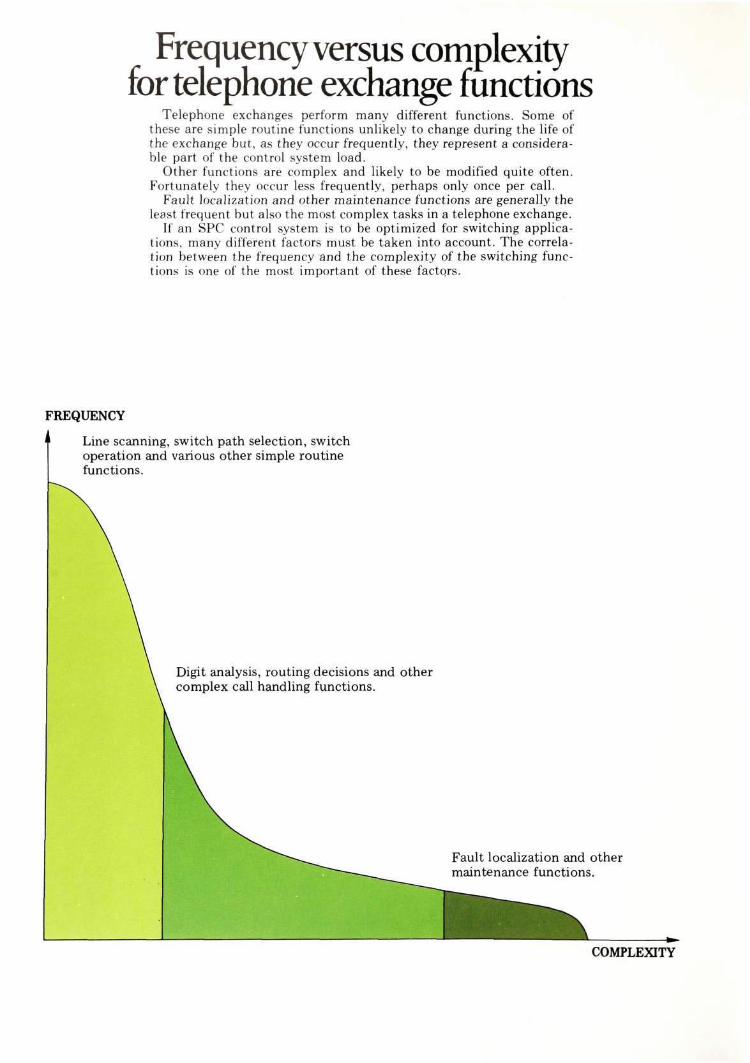
Frequency versus complexity for telephone exchange functions
Telephone exchanges perform many different functions. Some of these are simple routine functions unlikely to change during the life of the exchange but, as they occur frequently, they represent a considerable part of the control system load.
Other functions are complex and likely to be modified quite often. Fortunately they occur less frequently, perhaps only once per call.
Fault localization and other maintenance functions are generally the least frequent but also the most complex tasks in a telephone exchange.
If an SPC control system is to be optimized for switching applications, many different factors must be taken into account. The correlation between the frequency and the complexity of the switching functions is one of the most important of these factors.
FREQUENCY
Line scanning, switch path selection, switch operation and various other simple routine funct ions
i functions.
Digit analysis, routing decisions and other complex call handling functions.
Fault localization and other maintenance functions.
COMPLEXITY
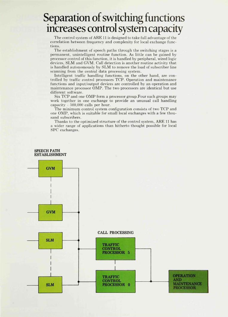
Separation of switching functions increases control system capacity
The control system of ARE 11 is designed to take full advantage of the correlation between frequency and complexity for local exchange functions.
The establishment of speech paths through the switching stages is a permanent, unintelligent routine function. As little can be gained by processor control of this function, it is handled by peripheral, wired logic devices, SLM and GVM. Call detection is another routine activity that is handled autonomously by SLM to remove the load of subscriber line scanning from the central data processing system.
Intelligent traffic handling functions, on the other hand, are controlled by traffic control processors TCP. Operation and maintenance functions and input/output devices are controlled by an operation and maintenance processor OMP. The two processors are identical but use different software.
Six TCP and one OMP form a processor group.Four such groups may work together in one exchange to provide an unusual call handling capacity - 500,000 calls per hour.
The minimum control system configuration consists of two TCP and one OMP, which is suitable for small local exchanges with a few thousand subscribers.
Thanks to the optimized structure of the control system, ARE 11 has a wider range of applications than hitherto thought possible for local SPC exchanges.
SPEECH PATH ESTABLISHMENT
GVM
1 1 1 1 1
GVM
SLM
1 1 1
1
SLM '
1
«^/\±J1J rrvw^i^ooiixvj
TRAFFIC CONTROL PROCESSOR 5
1
TRAFFIC CONTROL PROCESSOR 0
OPERATION AND MAINTENANCE PROCESSOR
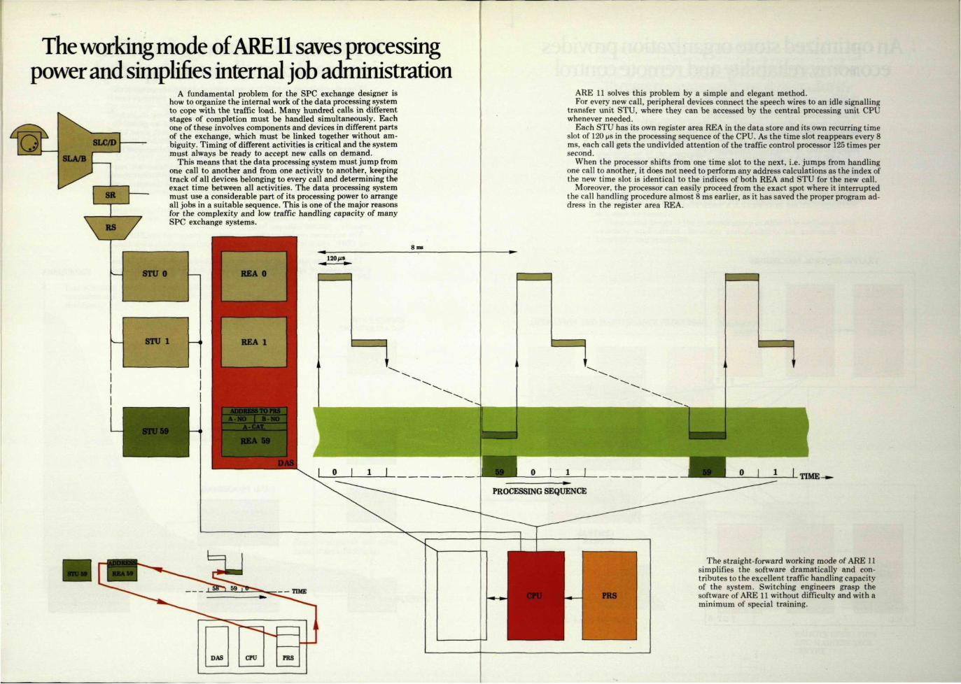
The working mode of ARE 11 saves processing power and simplifies internal job administration
A fundamental problem for the SPC exchange designer is how to organize the internal work of the data processing system to cope with the traffic load. Many hundred calls in different stages of completion must be handled simultaneously. Each one of these involves components and devices in different parts of the exchange, which must be linked together without ambiguity. Timing of different activities is critical and the system must always be ready to accept new calls on demand.
This means that the data processing system must jump from one call to another and from one activity to another, keeping track of all devices belonging to every call and determining the exact time between all activities. The data processing system must use a considerable part of its processing power to arrange all jobs in a suitable sequence. This is one of the major reasons for the complexity and low traffic handling capacity of many SPC exchange systems.
ARE 11 solves this problem by a simple and elegant method. For every new call, peripheral devices connect the speech wires to an idle signalling
transfer unit STU, where they can be accessed by the central processing unit CPU whenever needed.
Each STU has its own register area REA in the data store and its own recurring time slot of 120 ps in the processing sequence of the CPU. As the time slot reappears every 8 ms, each call gets the undivided attention of the traffic control processor 125 times per second.
When the processor shifts from one time slot to the next, i.e. jumps from handling one call to another, it does not need to perform any address calculations as the index of the new time slot is identical to the indices of both REA and STU for the new call.
Moreover, the processor can easily proceed from the exact spot where it interrupted the call handling procedure almost 8 ms earlier, as it has saved the proper program address in the register area REA.
TIME-
— TIME
DAS CPU PRS
The straight-forward working mode of ARE 11 simplifies the software dramatically and eon-tributes to the excellent traffic handling capacity of the system. Switching engineers grasp the software of ARE 11 without difficulty and with a minimum of special training.

An optimized store organization provides economy, reliability and remote control
The hardware structure of the multiprocessor data processing system of ARE 11 matches the simplicity and elegance of the software structure. The organization of program and data stores is carefully designed to suit telephone switching requirements.
Three types of information must be available in a true SPC system: 1) programs that control the traffic handling functions, 2) variable data that describes the progress of every call, and 3) semi-permanent reference data for analyses, translations etc.
In ARE 11 each traffic control processor TCP has its own program and data stores. Semi-permanent reference data is rarely accessed and is therefore stored in central stores, common to six TCP.
The data store is a dynamic MOS memory that is divided into 60 register areas REA. Each register area serves one call at a time and stores all temporary information about the call, including the address to
TRAFFIC CONTROL PROCESSORS
REA O
DATA STORE
REA 59
REA O
DATA STORE
REA 59 T C P 0
SUBSCRIBER CATEGORY STORE
TRANSLATION STORE
ABBREVIATED DIALLING STORE
CENTRAL STORES
the program that is to be executed during the next time slot. As the number of time slots is limited, the traffic control processor can never be overloaded. Momentary loss ofall information in the data store affects only those calls that are being handled at that moment.
The program store is a programmable read only memory — PROM — and the contents of this can never be lost or mutilated.
The programs define general functions, which are rarely changed, while the contents of the central stores give these functions the special significance that separates one exchange from another.
Everyday work like temporary disconnection of non-paying subscribers or changes of the routing pattern are readily performed at the exchange or from a remote operation and maintenance centre OMC by modification of the contents of the central stores.
If the functions themselves are to be changed, for example if a new signalling system is to be added, a new program board is simply added to the program store. Standard interfaces provide functional modulari
Software faults are not easily spread by the CPU, as it normally writes only in the data store where a software fault has little effect and will soon be erased.
The general design of the processor group in ARE 11 is well adapted to switching applications. Economy and flexibility are combined with simplicity and reliability.
OPERATION AND MAINTENANCE PROCESSOR
OMP
MODEM
LOCAL I / O - DEVICES
MODEM - ,
^ OMC
REMOTE OPERATION AND MAINTENANCE CENTRE
'izm
^
1 ' - ™ ^ ^ ^
L'l [ ' Ifm 1 _JT8a r E -
K • :

Practical design
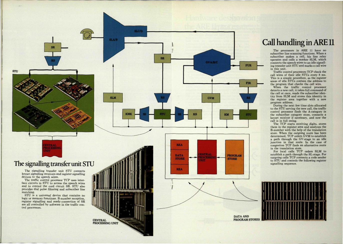
The signalling transfer unit STU The signalling transfer unit STU connects
keyset signalling receivers and register signalling devices to the speech wires.
The traffic control processor TCP uses interface circuits in STU to access the speech wires and to control the cord circuit SR. STU also provides dial pulse filtering and subscriber line matching.
STU is a universal device that contains no logic or memory functions. B-number reception, register signalling and ready-connection of SR are all controlled by software in the traffic control processors.
Call handling in ARE 11 The processors in ARE 11 have no
subscriber line scanning functions. When a subscriber makes a call, his line relay operates and calls a marker SLM, which connects the speech wires to an idle signall-
— ing transfer unit STU and marks a call wire in this unit.
Traffic control processors TCP check the call wires of their idle STUs every 8 ms. This is a simple procedure, as the register areas of idle STUs contain the address to
~ the program that checks the call wire. When the traffic control processor
detects a new call, it takes full command of the call at once, reads the subscriber identity from SLM and stores this identity in the register area together with a new program address.
During the next few time slots allocated to the STU serving the new call, the traffic control processor finds the A-category in the subscriber category store, connects a keyset receiver if necessary, and now the call is in full swing.
The TCP starts receiving digits, stores them in the register area and analyzes the B-number with the help of the translation store. When the outgoing route has been determined, TCP orders GVM to establish a path through the GV-stage to an idle junction in that route. In the case of congestion TCP finds an alternative route in the translation store.
For local calls TCP orders SLM to establish a path through the SL-stage. For outgoing calls TCP connects a code sender to STU and controls the following register signalling sequence.
CENTRAL PROCESSING UNIT
DATA AND PROGRAM STORES
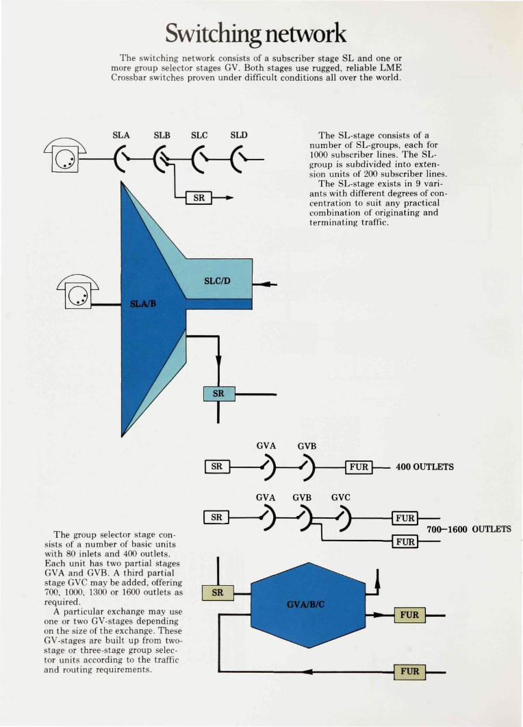
Switching network The switching network consists of a subscriber stage SL and one or
more group selector stages GV. Both stages use rugged, reliable LME Crossbar switches proven under difficult conditions all over the world.
SLA SLB SLC SLD The SL-stage consists of a number of SL-groups, each for 1000 subscriber lines. The SL-group is subdivided into extension units of 200 subscriber lines.
The SL-stage exists in 9 variants with different degrees of concentration to suit any practical combination of originating and terminating traffic.
GVA GVB
400 OUTLETS
GVA GVB GVC
The group selector stage consists of a number of basic units with 80 inlets and 400 outlets. Each unit has two partial stages GVA and GVB. A third partial stage GVC may be added, offering 700, 1000, 1300 or 1600 outlets as required.
A particular exchange may use one or two GV-stages depending on the size of the exchange. These GV-stages are built up from two-stage or three-stage group selector units according to the traffic and routing requirements.
700-1600 OUTLETS

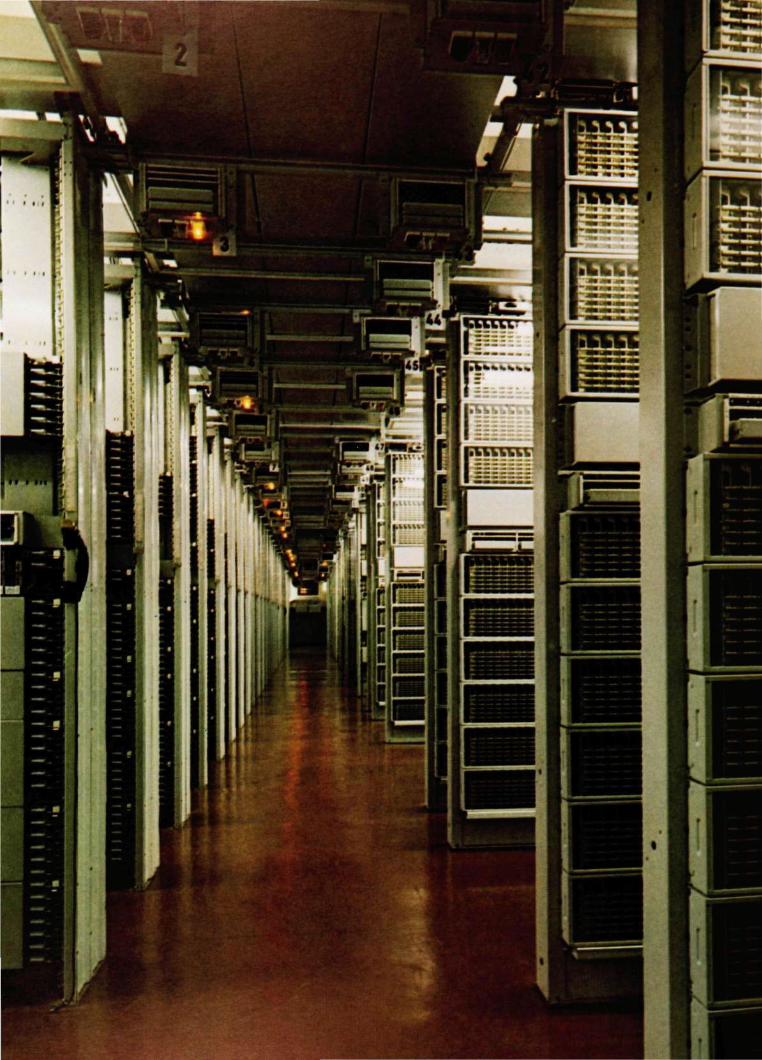
Hardware design of the ARE 11 processor
The picture shows the ARE 11 processor rack with a traffic control processor TCP in the upper half and an operation and maintenance processor OMP in the lower half of the rack. The only visible difference between these is the I/O terminal interface at the bottom of the rack. The memory contents are, of course, also different.
The central processing unit is a modern microprogrammed machine utilizing fast TTL logic throughout, and it occupies only one two-level shelf. 5 V power units for the central processing units are housed in the middle of the rack together with a control panel for direct access to the processors.
The two-level shelf above the central processing unit contains the program and data stores. The data store is a fast dynamic random access MOS memory, while the program store is a programmable read only memory with the information permanently burnt into PROM chips. The program memory contents can never be lost or mutilated. They can nonetheless be easily changed or extended whenever necessary.
ARE 11 fullfils all the requirements of a modern SPC local exchange with a very moderate program volume of 25,000 instructions. The software efficiency has been achieved by a highly successful combination of instruction list, data structure and operating system.
Modernization of local networks
with ARE 11 Due to the modular structure of the data processing control system,
ARE 11 covers a remarkable range - from about 1000 up to 80,000 subscribers. And it is suitable in all local exchange applications.
ARE 11 provides a practical and sensible solution to the modernization of any local telephone network. Additional, substantial advantages are gained if the network contains ARF local exchanges.
In this case the administration can choose between keeping the existing exchanges intact, extending them with ARF or ARE 11 equipment, or converting them to ARE 11 exchanges. It has full freedom to choose the most convenient rate of introduction and penetration of new equipment and new services.
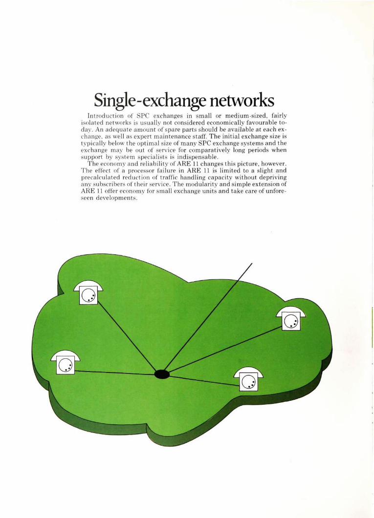
Single-exchange networks Introduction of SPC exchanges in small or medium-sized, fairly
isolated networks is usually not considered economically favourable today. An adequate amount of spare parts should be available at each exchange, as well as expert maintenance staff. The initial exchange size is typically below the optimal size of many SPC exchange systems and the exchange may be out of service for comparatively long periods when support by system specialists is indispensable.
The economy and reliability of ARE 11 changes this picture, however. The effect of a processor failure in ARE 11 is limited to a slight and precalculated reduction of traffic handling capacity without depriving any subscribers of their service. The modularity and simple extension of ARE 11 offer economy for small exchange units and take care of unforeseen developments.
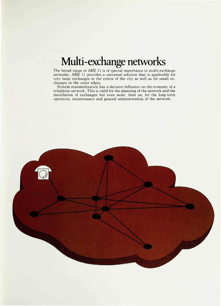
Multi-exchange networks The broad range of ARE 11 is of special importance in multi-exchange networks. ARE 11 provides a universal solution that is applicable for very large exchanges in the centre of the city as well as for small exchanges in the outer edges.
System standardization has a decisive influence on the economy of a telephone network. This is valid for the planning of the network and the installation of exchanges but even more, later on, for the long-term operation, maintenance and general administration of the network.
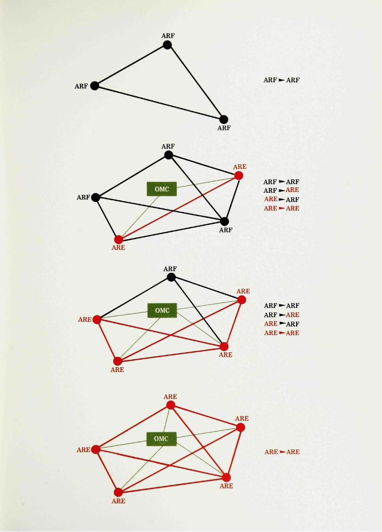
Modernization of ARF local networks When SPC exchanges are introduced into an existing network, sub
scriber services and operation and maintenance methods will differ considerably in the new and the existing parts of the network.
Where the original, homogenous network had only one traffic case, the introduction of SPC creates four traffic cases, which depend on the types and facilities of the originating and terminating exchanges.
The ultimate aim is, of course, to introduce SPC all over the network. But until then, segregated subscriber services can cause confusion. The pricing and the limited availability of the new services may give rise to problems.
If the existing network employs ARF exchanges, however, the transitional period may be shortened considerably. In this case the existing exchanges may be converted to ARE 11 standards one by one or several at a time.
A minimum investment provides the existing exchanges with the same services as the new ones. Remote control from an operation and maintenance centre OMC lowers the cost for the administration of the network.
No other solution will lead to a modern, homogenous local network at a comparable expenditure of time, cost and effort.
ARF
ARF ARF —ARF
ARF
ARF
ARE
ARF
ARF—ARF ARF—ARE ARE—ARF ARE —ARE
ARE
ARF
ARE
ARE
ARF—ARF ARF —ARE ARE—ARF ARE —ARE
ARE
ARE
ARE
ARE ARE—ARE
ARE
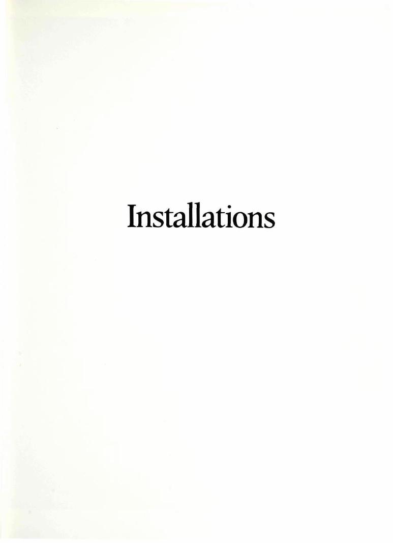
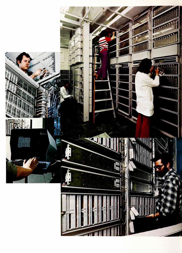
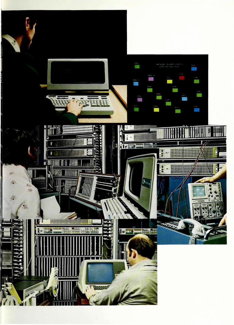
Installations
Technical data

Technical data for ARE 11 Traffic handling properties
Max. no. of subscribers 80,000 Extension module 200 subs. No. of subscriber stage variants 9 Traffic per subscriber Up to 0.23 erl Call handling capacity at 80,000 subs. 500,000 calls/hour PBX-groups may be distributed over 10,000 multiple positions
Group selector stage with 2 or 3 partial stages and 400 - 1600 outlets Alternative routing
Max. no. of line signalling systems Max. no. of simultaneous register signalling systems for outgoing traffic Common channel signalling
Digit analysis No. of destinations B-number store capacity
Charging Conventional electromechanical meters Electronic for national and international charging in ARE 11 Max. no. of tariffs Max. no. of tariff classes Charge pulse intervals
Unlimited
Unlimited
4
256 16 digits
127 127 0 . 5 - 1,000 s
Subscriber facilities Push-button set Hot line Abbreviated dialling Priority
Future facilities Add-on conference Call waiting Hold for enquiry
A-categories B-categories
Virtually un 64
Operation and maintenance properties Supervision of blocking, seizure and fault ratio for individual devices and device groups, processors, central devices, subscriber lines, etc.
Remote control from Operation and Maintenance Centre (OMC) for
modification of subscriber category modification of traffic routing data supervision fault indication statistics disturbance recording of live traffic traffic recording of device groups and routes
Data processing system Primary interval 8 ms Max. program store volume 32 K 16 Max. data store volume 32 K 8 Number of instructions 63 Average instruction time 2 \js Microinstruction time 250 ns Multiprocessor system with roving spare equipment
Max. no. of Traffic Control Processors 4 x 6 Max. no. of Operation and Maintenance Processors 4 x 1 Working mode Time division with
fixed time slots
The contents of this book are subject to revision without notice, due to continued progress in design and manufacture.

Printing in Sweden: Stellan Stål 1976

I
Telephone Exchange Division S-126 25 Stockholm Sweden