are nearly all tidal stream turbines designs wrong?
DESCRIPTION
Are Nearly all Tidal Stream Turbines Designs Wrong?. Stephen Salter Institute for Energy Systems University of Edinburgh [email protected] www.see.ed.ac.uk/~shs. Cells are 1 minute of arc lat. 1.5 minutes long = 2.617 km 2 . Power = 6.165 TW x Cf Courtesy Proudman Labs. - PowerPoint PPT PresentationTRANSCRIPT

Are Nearly all Tidal Stream Turbines Designs Wrong?
Stephen Salter
Institute for Energy Systems
University of Edinburgh
www.see.ed.ac.uk/~shs

Cells are 1 minute of arc lat. 1.5 minutes long = 2.617 km2.
Power = 6.165 TW x CfCourtesy Proudman Labs

Peak spring Pentland sea-bed friction
= 6.165 TeraWatt x Cf
But what is Cf ?
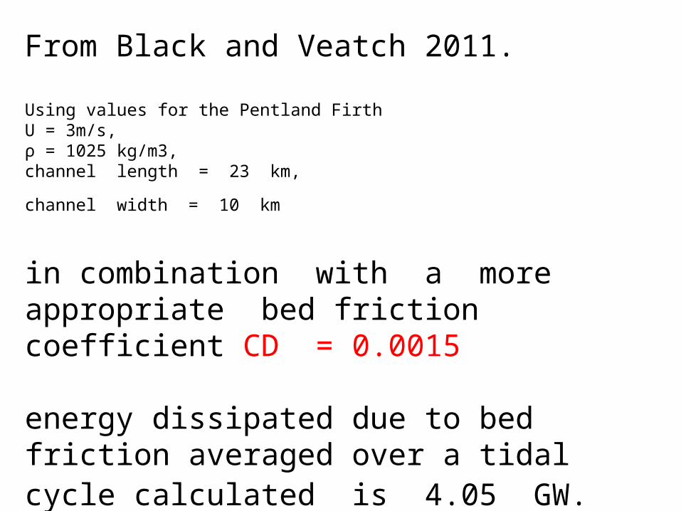
From Black and Veatch 2011.
Using values for the Pentland Firth U = 3m/s, ρ = 1025 kg/m3, channel length = 23 km,
channel width = 10 km
in combination with a more appropriate bed friction coefficient CD = 0.0015 energy dissipated due to bed friction averaged over a tidal cycle calculated is 4.05 GW.


Laminaria Hyperborea (kelp) are found along the
edges of the Pentland Firth at depths up to 30 m.
Length can reach 3.5 metres.
Cf = ?
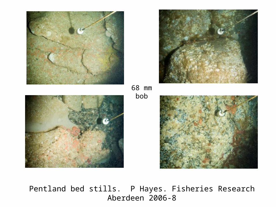
Pentland bed stills. P Hayes. Fisheries Research Aberdeen 2006-8
68 mm bob
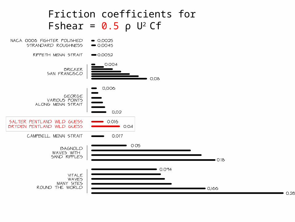
Friction coefficients for Fshear = 0.5 ρ U2 Cf


Source CF for ½ ρU2
Campbell, Simpson and Allen Estuarine Coastal and Shelf Science vol 46 1998.
Menai strait(0.0086 ± 0.0002) x 2 = 0.0172
George K. Hydrographic Journal October 2005 Positions along Menai strait0.006, 0.008, 0.013, 0.015, 0.018, 0.02
Abbot and von Doenhoff.Dover 1959.
One side of a NACA 0006 fighter wing at 0 deg incidence. Rey No 6E6.
Polished 0.0025Standard roughness 0.0045
Bricker, Inagaki and Monismith. ASCE Journal of Hydraulic Engineering June 2005.
Combinations of waves and currents with results depending on ratio of current at one metre above
bed to maximum orbital wave velocity.San Franciso Bay. Silt and fine sand.
0.004 (low waves) to 0.08
Rippeth, Williams and Simpson. Journal of Physical Oceanography vol 32, 2002.
Menai Strait with ADCP and mean depth current0.0052 ± 0.0004
Vitale ASCE Journal of Waterway,Port, Coastal and ocean Division August 1979.
Average wave friction from many sites 0.094, 0.1, 0.106, 0.116,0.166, 0.28
Bagnold. Proc. Roy. Soc. December 1946. Waves with sand ripples0.05, 0.144, 0.16, 0.18,

6.165 TeraWatt x 0.04
= 247 GWX 0.38 = 93.7 GW
at peak spring

O’Doherty DM. Mason-Jones Morris, O’DohertyT, Bryne, Pricket, Grosvenor.
Interaction of marine turbines in close proximity.
EWTEC 2011
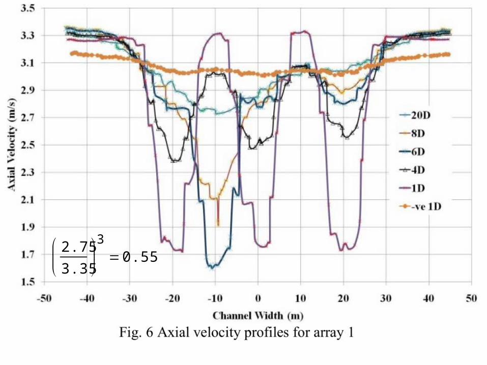
2.75
3.35
3
0.55

2.75
3.3
3
0.58

NASA

Edinburgh vertical-axis, variable pitch with rim power take off.
EWTEC Patras 1998


70 60 50 40 30 20 10 0 10 20 30 40 50 60 700
0.2
0.4
0.6
0.8
1
1.2Downstream force on a 140 diameter rotor as a fraction of ideal
1.2
0
fdsi 4
FDSi 4
DR
2
DR2
Xi


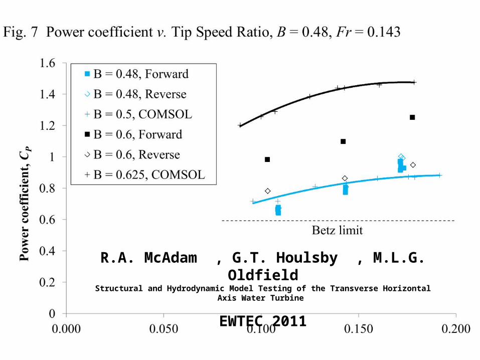
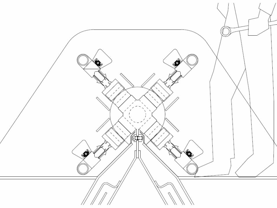
R.A. McAdam , G.T. Houlsby , M.L.G. OldfieldStructural and Hydrodynamic Model Testing of the Transverse Horizontal Axis Water Turbine
EWTEC 2011


Speed up x 30Range up x 6000
Payload up x 20,000Cost down ÷ 100


Something for the simpletons

Variable pitch advantagesEasy tow to installation site with 2.5% drag of circular members
Agile self propulsion
Instant disconnection of delivered power
Relief of bending stress in rings
Avoidance of cavitation
Double performance at lower tip speed ratios for 1.5% extra cost
Online conversion from open flow field to close packed
Survivor repulsion
Sibling assistance
Reactive loading to tune Pentland Firth to M2
Potential for delayed generation

Degreeslag
Phase by zero crossings 63.4
Phase by real and imaginary M2 spectral FFT peaks of slope and velocity
58.1
Phase by voltage induced by the earth’s magnetic field 68

Problems for horizontal-axis axial-flow rotors
Lower efficiency near the hub. Low packing-fraction means poor use of resource. Longer power cables. Higher bending moments at the blade roots. Coincidence of shear and bending stress. Vortex shedding at blade tips. Tower leverage. Hydrodynamic wake pollution. Sensitivity to flow direction change. Volume constraint for pitch mechanism. Betz limit. Bearing leverage. Bending moments limit power rating. Hydrostatic pressure variation. Submerged power-conversion mechanism. Lack of space for power conversion. Submerged main bearings. Less power smoothing. More expense for tapered and twisted hydrofoils. No bridge option. Need for high rubbing seal velocity . . . . . . . . . . . . .