ariss lightweight l and s-band antenna
TRANSCRIPT
7/28/2019 Ariss Lightweight l and S-band Antenna
http://slidepdf.com/reader/full/ariss-lightweight-l-and-s-band-antenna 1/4
Lightweight L and S-Band Antenna Fed by Three-Strip Directional Couplers
Pawel Kabacik*(1), Grzegorz Jaworski(1), Monika Hornik (1), Tomasz Maleszka(1)
(1) Wroclaw University of Technology, 50-370 Wroclaw, Poland
E-mail to the authors: [email protected]
Introduction
Radioamateur installations in space migrates to lower microwave frequencies [1].That trend establishes a challenge in designing antennas needed to serve
spaceborne transceivers. The radioamateur equipment must be lightweight anddoes not call for deployment mechanism. Reliability requirements are high, as not
often an onboard installation can be added to satellites or to modulesof International Space Station. The lightweight antennas of excellent mechanical
performance can be manufactured with composite panels [2]. To maintain a goodlink budget for users spread within several thousands of kilometers within radio
horizon seen from spacecraft, superior quality of circular polarization is advised.Presently, it is feasible to provide a good quality of the circular polarization
within the main beam of a patch element. To accomplish it in a wide band, patchmust be fed through a pair of shaped coupling slots [3]. To support wideband
circular polarization operation, the directional coupler in the feed circuit mustkeep the constant 90° phase shift and the amplitude balance between
the transmission and coupling ports in the wide band. A good candidate is thethree-strip coupler proposed by Sachse and Sawicki [4].
Antenna design and its performance
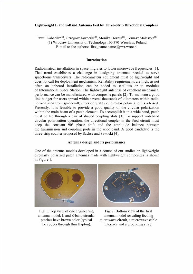
One of the antenna models developed in a course of our studies on lightweight
circularly polarized patch antennas made with lightweight composites is shownin Figure 1.
Fig. 1. Top view of one engineering
antenna model; L and S-band circular patches have brown color (typical
for copper through thin Kapton).
Fig. 2. Bottom view of the first
antenna model revealing feedingmicrowave circuit, a microwave cable
interface and a grounding strap.
7/28/2019 Ariss Lightweight l and S-band Antenna
http://slidepdf.com/reader/full/ariss-lightweight-l-and-s-band-antenna 2/4
The antenna has two circular patches
to optimize the performance in the L andS band. The feed network made
in microstrip technique is located at the
bottom side of the antenna and is shownin Figure 2. The circuit is composedof two polarizers and a diplexer.
The polarizers are three-strip couplerswith printed lines arranged in a way that
there is no need to use solderedconnection between two layers. The only
solder is used at match loads at theisolated ports. The diplexer is made with
two frequency traps, one in each branch.Traps are made with open and shorten
stubs. The shorten stub makes a DCgrounding of the antenna input.
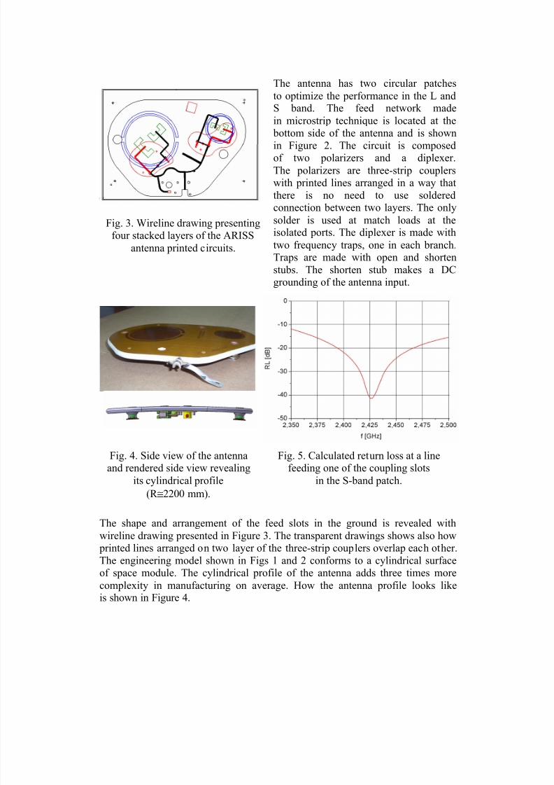
The shape and arrangement of the feed slots in the ground is revealed with
wireline drawing presented in Figure 3. The transparent drawings shows also how
printed lines arranged on two layer of the three-strip couplers overlap each other.The engineering model shown in Figs 1 and 2 conforms to a cylindrical surfaceof space module. The cylindrical profile of the antenna adds three times more
complexity in manufacturing on average. How the antenna profile looks likeis shown in Figure 4.
Fig. 3. Wireline drawing presentingfour stacked layers of the ARISS
antenna printed circuits.
Fig. 4. Side view of the antennaand rendered side view revealing
its cylindrical profile
(R ≅2200 mm).
Fig. 5. Calculated return loss at a linefeeding one of the coupling slots
in the S-band patch.
7/28/2019 Ariss Lightweight l and S-band Antenna
http://slidepdf.com/reader/full/ariss-lightweight-l-and-s-band-antenna 3/4
1.9 2 2.1 2.2 2.3 2.4 2.5 2.6 2.7 2.8 2.9
Frequency (GHz)
coupler_2400_MHz
-40
-30
-20
-10
0
-4
-3.5
-3
-2.5
-2
DB(|S[1,1]|) (L)
coupler_2400_MHz
DB(|S[2,1]|) (L)
coupler_2400_MHz
DB(|S[3,1]|) (R)
coupler_2400_MHz
DB(|S[4,1]|) (R)
coupler_2400_MHz
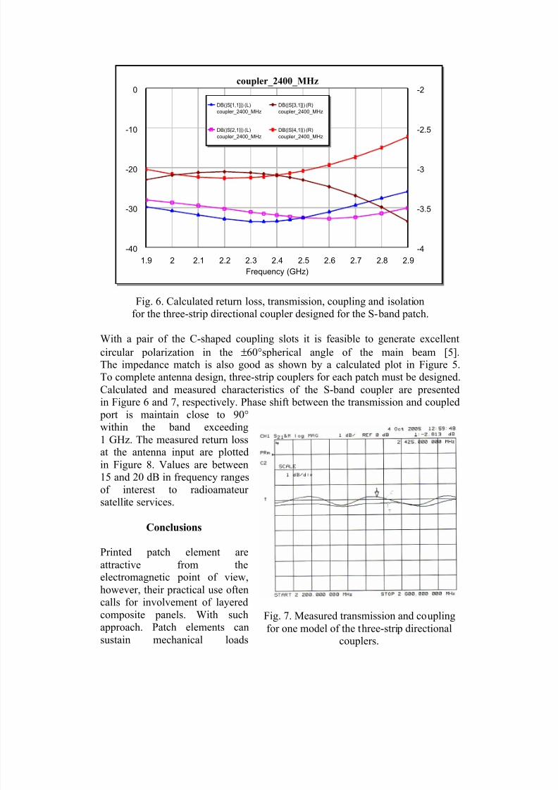
Fig. 6. Calculated return loss, transmission, coupling and isolationfor the three-strip directional coupler designed for the S-band patch.
With a pair of the C-shaped coupling slots it is feasible to generate excellent
circular polarization in the ±60°spherical angle of the main beam [5].The impedance match is also good as shown by a calculated plot in Figure 5.To complete antenna design, three-strip couplers for each patch must be designed.
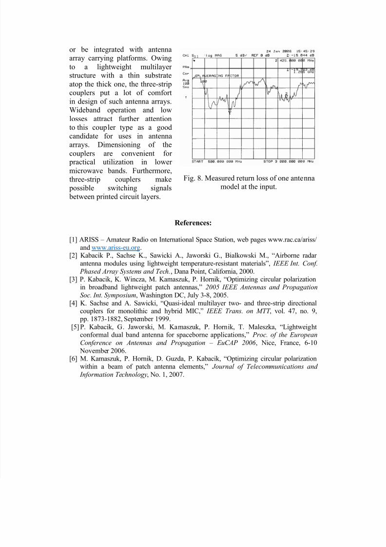
Calculated and measured characteristics of the S-band coupler are presentedin Figure 6 and 7, respectively. Phase shift between the transmission and coupled
port is maintain close to 90°within the band exceeding
1 GHz. The measured return lossat the antenna input are plotted
in Figure 8. Values are between15 and 20 dB in frequency ranges
of interest to radioamateur satellite services.
Conclusions
Printed patch element areattractive from theelectromagnetic point of view,
however, their practical use oftencalls for involvement of layered
composite panels. With suchapproach. Patch elements can
sustain mechanical loads
Fig. 7. Measured transmission and coupling
for one model of the three-strip directionalcouplers.
7/28/2019 Ariss Lightweight l and S-band Antenna
http://slidepdf.com/reader/full/ariss-lightweight-l-and-s-band-antenna 4/4
or be integrated with antennaarray carrying platforms. Owing
to a lightweight multilayer structure with a thin substrate
atop the thick one, the three-strip
couplers put a lot of comfortin design of such antenna arrays.Wideband operation and low
losses attract further attentionto this coupler type as a good
candidate for uses in antennaarrays. Dimensioning of the
couplers are convenient for practical utilization in lower
microwave bands. Furthermore,three-strip couplers make
possible switching signals between printed circuit layers.
References:
[1] ARISS – Amateur Radio on International Space Station, web pages www.rac.ca/ariss/
and www.ariss-eu.org.[2] Kabacik P., Sachse K., Sawicki A., Jaworski G., Bialkowski M., “Airborne radar
antenna modules using lightweight temperature-resistant materials”, IEEE Int. Conf.
Phased Array Systems and Tech., Dana Point, California, 2000.[3] P. Kabacik, K. Wincza, M. Kamaszuk, P. Hornik, “Optimizing circular polarization
in broadband lightweight patch antennas,” 2005 IEEE Antennas and PropagationSoc. Int. Symposium, Washington DC, July 3-8, 2005.
[4] K. Sachse and A. Sawicki, “Quasi-ideal multilayer two- and three-strip directionalcouplers for monolithic and hybrid MIC,” IEEE Trans. on MTT , vol. 47, no. 9,
pp. 1873-1882, September 1999.
[5] P. Kabacik, G. Jaworski, M. Kamaszuk, P. Hornik, T. Maleszka, “Lightweightconformal dual band antenna for spaceborne applications,” Proc. of the European
Conference on Antennas and Propagation – EuCAP 2006 , Nice, France, 6-10
November 2006.[6] M. Kamaszuk, P. Hornik, D. Guzda, P. Kabacik, “Optimizing circular polarization
within a beam of patch antenna elements,” Journal of Telecommunications and
Information Technology, No. 1, 2007.
Fig. 8. Measured return loss of one antennamodel at the input.