armorguard permanent steel barrier gate - qmb · armorguard® permanent steel barrier gate nchrp...
TRANSCRIPT
INSTALLATION MANUAL
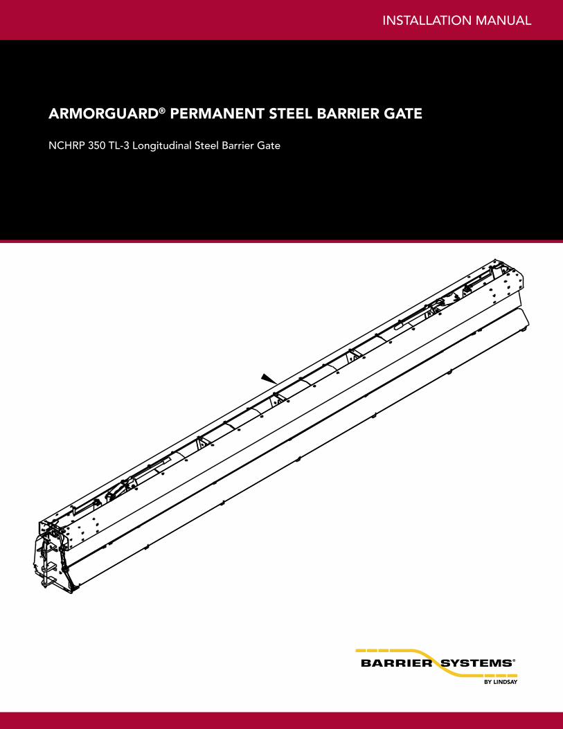
ArmorGuArd® PErmANENT STEEL BArrIEr GATE
NCHRP 350 TL-3 Longitudinal Steel Barrier Gate
Lindsay Transportation Solutions Sales and Services, Inc (888) 800-3691 [U.S. toll free] or +1 (707) 374-6800 Lindsay Transportation Solutions Sales and Services, Inc (888) 800-3691 [U.S. toll free] or +1 (707) 374-68002
2 2 3 3 4 8 14
PREFACE
INTRODUCTION
The AGS has been fully tested in accordance with the evaluation parameters in NCHRP Report 350, Test Lev-els 3 (100 km/hr).
The system is a heavily reinforced steel barrier that is designed for emergency openings. It is ideally suited for permanent and stationary work zone barriers where emergency vehicles, maintenance crews and emergency evacuation access may be needed and positive barrier protection is required.
The system should be installed on a smooth firm surface that is capable of supporting the weight of the system. Generally a Portland Concrete Cement (PCC) surface is preferred but the system has been successfully installed and used on an Asphaltic Concrete surface. Please refer to Appendix B (Page 16).
ArmorGuard ® Gate System Section Splice and Transition Installation Instructions
Table of Contents
Preface …………………………………………… Introduction …………………………………….. System Overview ………………………………… Required Tools ………………………………….. Section Splicing Instructions …………………… Transition Installation Instruction ……………… Limitations and Warnings …..…………………
Appendix A. Anchoring Material Options ……. 15 B. Anchoring Foundation and
Barrier Cutout ……………………..16 C. System Assembly Drawings ...…. 18 D. Maintenance …………………….. 29
The Barrier Systems, Inc. (BSI), ArmorGuard Gate
System (AGS), incorporates the newest roadside safety materials and engineering processes.
As with any roadside safety device, the AGS must be in-stalled properly to insure proper performance. Thoroughly review and fully understand the installation instructions and product limitations before starting the installation. An instructional video is available from BSI to help explain the general installation requirements. Watch and fully understand the AGS Section Splice and Hinge / Transition Installation and Assembly Video before attempting to install the system. Do not start the installation without the proper plans and tools required for installation.
If you need additional information, or have questions about the ArmorGuard Gate System, please call the BSI Cus-tomer Service Department at (888) 800-3691 (U.S toll free) or (707) 374-6800.
INSTaLLaTIoN MaNUaL
Lindsay Transportation Solutions Sales and Services, Inc (888) 800-3691 [U.S. toll free] or +1 (707) 374-6800 3
BEFORE INSTALLATION
Placement and use of the ArmorGuard Gate System should be accomplished in accordance with the guide-lines and recommendations set forth in the “AASHTO Roadside Design Guide,” FHWA memoranda and other state and local standards.
The AGS is a highly engineered safety device made up of a relatively small number of parts. Before starting the assembly, become familiar with the basic elements that make up the system.
Depending on the size of the system ordered, the gate sections will be shipped separately and the transition parts will be shipped on pallets. Assembly of the system is typically done at the worksite. (If preferred, the system can be assembled “off-site” and set into position as one piece, with a forklift or crane.)
8 and 12 meter gates are shipped fully assembled. 16 meter gates are shipped in (2) 8-meter sections with tran-sitions on pallets.
Before beginning the assembly of the system, check the packing list to be certain that all of the system compo-nents were included in the shipment.
NOTE: It is important to determine the system’s installation position to optimize proper function and transition.
SYSTEM OVERVIEW
Longitudinal barriers are highway safety devices whose primary functions are to prevent vehicular penetration and to safely redirect an errant vehicle away from road-side or median hazards. The ArmorGuard Gate system is used as a moveable longitudinal barrier section that can be installed in openings of rigid barrier systems. The system is hinged at both ends and uses a compressed air powered jacking system or manual jack system to raise the gate section onto casters. This enables the system to be unhinged and swung open from either end, or the whole gate section can be disconnected at both ends and moved in any direction. The purpose of the system is to create a crashworthy closure for rigid longitudinal bar-rier openings that is capable of being opened by no more than two people in less than 5 minutes.
The system is approximately 28 inches (700 mm) wide and is 33 inches (830 mm) high. It is available in 4-me-ter (13’) increments from 8 meters to 16 meters (26 to 52 feet) in length. The system can be quickly and easily opened or closed without expensive electrical power sup-plies or sophisticated control systems. Positive security can also be provided.
REQUIRED TOOLS
1/2” (12 mm) medium depth sockets
1/2” (12 mm) Ratchet with extensions
Rotohammer for drilling holes in concrete
Torque wrenches
Measuring tape
Safety Equipment: Glasses, Gloves 1/2” (12
mm) Air impact wrench w/ sockets Note: The tools list above is a general recommenda-
tion. Depending on the specific characteristics of the job site, different tools may be necessary.
aRMoRGUaRD® PERMaNENT GaTE
Lindsay Transportation Solutions Sales and Services, Inc (888) 800-3691 [U.S. toll free] or +1 (707) 374-6800 Lindsay Transportation Solutions Sales and Services, Inc (888) 800-3691 [U.S. toll free] or +1 (707) 374-68004
Figure 1.
Figure 2.
Step 2
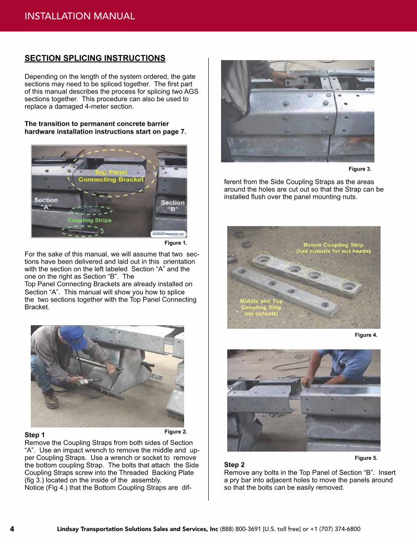
SECTION SPLICING INSTRUCTIONS
Depending on the length of the system ordered, the gate sections may need to be spliced together. The first part of this manual describes the process for splicing two AGS sections together. This procedure can also be used to replace a damaged 4-meter section.
The transition to permanent concrete barrier hardware installation instructions start on page 7.
For the sake of this manual, we will assume that two sec-tions have been delivered and laid out in this orientation with the section on the left labeled Section “A” and the one on the right as Section “B”. The Top Panel Connecting Brackets are already installed on Section “A”. This manual will show you how to splice the two sections together with the Top Panel Connecting Bracket.
Step 1 Remove the Coupling Straps from both sides of Section “A”. Use an impact wrench to remove the middle and up-per Coupling Straps. Use a wrench or socket to remove the bottom coupling Strap. The bolts that attach the Side Coupling Straps screw into the Threaded Backing Plate (fig 3.) located on the inside of the assembly. Notice (Fig 4.) that the Bottom Coupling Straps are dif-
Figure 3.
ferent from the Side Coupling Straps as the areas around the holes are cut out so that the Strap can be installed flush over the panel mounting nuts.
Figure 4.
Figure 5.
Remove any bolts in the Top Panel of Section “B”. Insert a pry bar into adjacent holes to move the panels around so that the bolts can be easily removed.
INSTaLLaTIoN MaNUaL
Lindsay Transportation Solutions Sales and Services, Inc (888) 800-3691 [U.S. toll free] or +1 (707) 374-6800 5
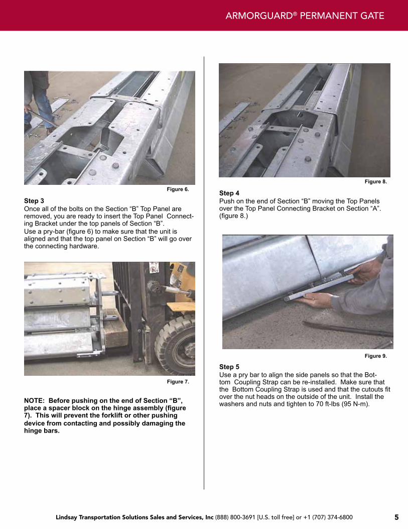
Figure 6.
Step 3 Once all of the bolts on the Section “B” Top Panel are removed, you are ready to insert the Top Panel Connect-ing Bracket under the top panels of Section “B”. Use a pry-bar (figure 6) to make sure that the unit is aligned and that the top panel on Section “B” will go over the connecting hardware.
Figure 7.
NOTE: Before pushing on the end of Section “B”, place a spacer block on the hinge assembly (figure 7). This will prevent the forklift or other pushing device from contacting and possibly damaging the hinge bars.
Figure 8.
Step 4 Push on the end of Section “B” moving the Top Panels over the Top Panel Connecting Bracket on Section “A”. (figure 8.)
Figure 9.
Step 5 Use a pry bar to align the side panels so that the Bot-tom Coupling Strap can be re-installed. Make sure that the Bottom Coupling Strap is used and that the cutouts fit over the nut heads on the outside of the unit. Install the washers and nuts and tighten to 70 ft-lbs (95 N-m).
aRMoRGUaRD® PERMaNENT GaTE
Lindsay Transportation Solutions Sales and Services, Inc (888) 800-3691 [U.S. toll free] or +1 (707) 374-6800 Lindsay Transportation Solutions Sales and Services, Inc (888) 800-3691 [U.S. toll free] or +1 (707) 374-68006
INSTaLLaTIoN MaNUaL
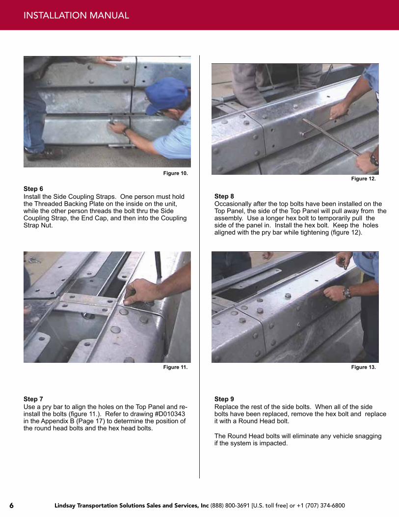
Figure 10.
Figure 11.
Step 8
Step 9 Replace the rest of the side bolts. When all of the side bolts have been replaced, remove the hex bolt and replace it with a Round Head bolt.
The Round Head bolts will eliminate any vehicle snagging if the system is impacted.
Step 6 Install the Side Coupling Straps. One person must hold the Threaded Backing Plate on the inside on the unit, while the other person threads the bolt thru the Side Coupling Strap, the End Cap, and then into the Coupling Strap Nut.
Step 7 Use a pry bar to align the holes on the Top Panel and re-install the bolts (figure 11.). Refer to drawing #D010343 in the Appendix B (Page 17) to determine the position of the round head bolts and the hex head bolts.
Figure 12.
Occasionally after the top bolts have been installed on the Top Panel, the side of the Top Panel will pull away from the assembly. Use a longer hex bolt to temporarily pull the side of the panel in. Install the hex bolt. Keep the holes aligned with the pry bar while tightening (figure 12).
Figure 13.
Lindsay Transportation Solutions Sales and Services, Inc (888) 800-3691 [U.S. toll free] or +1 (707) 374-6800 7
aRMoRGUaRD® PERMaNENT GaTE
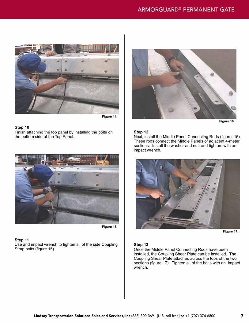
Figure 14.
Figure 15.
Step 12
Step 13 Once the Middle Panel Connecting Rods have been installed, the Coupling Shear Plate can be installed. The Coupling Shear Plate attaches across the tops of the two sections (figure 17). Tighten all of the bolts with an impact wrench.
Step 10 Finish attaching the top panel by installing the bolts on the bottom side of the Top Panel.
Step 11 Use and impact wrench to tighten all of the side Coupling Strap bolts (figure 15).
Figure 16.
Next, install the Middle Panel Connecting Rods (figure 16). These rods connect the Middle Panels of adjacent 4-meter sections. Install the washer and nut, and tighten with an impact wrench.
Figure 17.
Lindsay Transportation Solutions Sales and Services, Inc (888) 800-3691 [U.S. toll free] or +1 (707) 374-6800 Lindsay Transportation Solutions Sales and Services, Inc (888) 800-3691 [U.S. toll free] or +1 (707) 374-68008
INSTaLLaTIoN MaNUaL
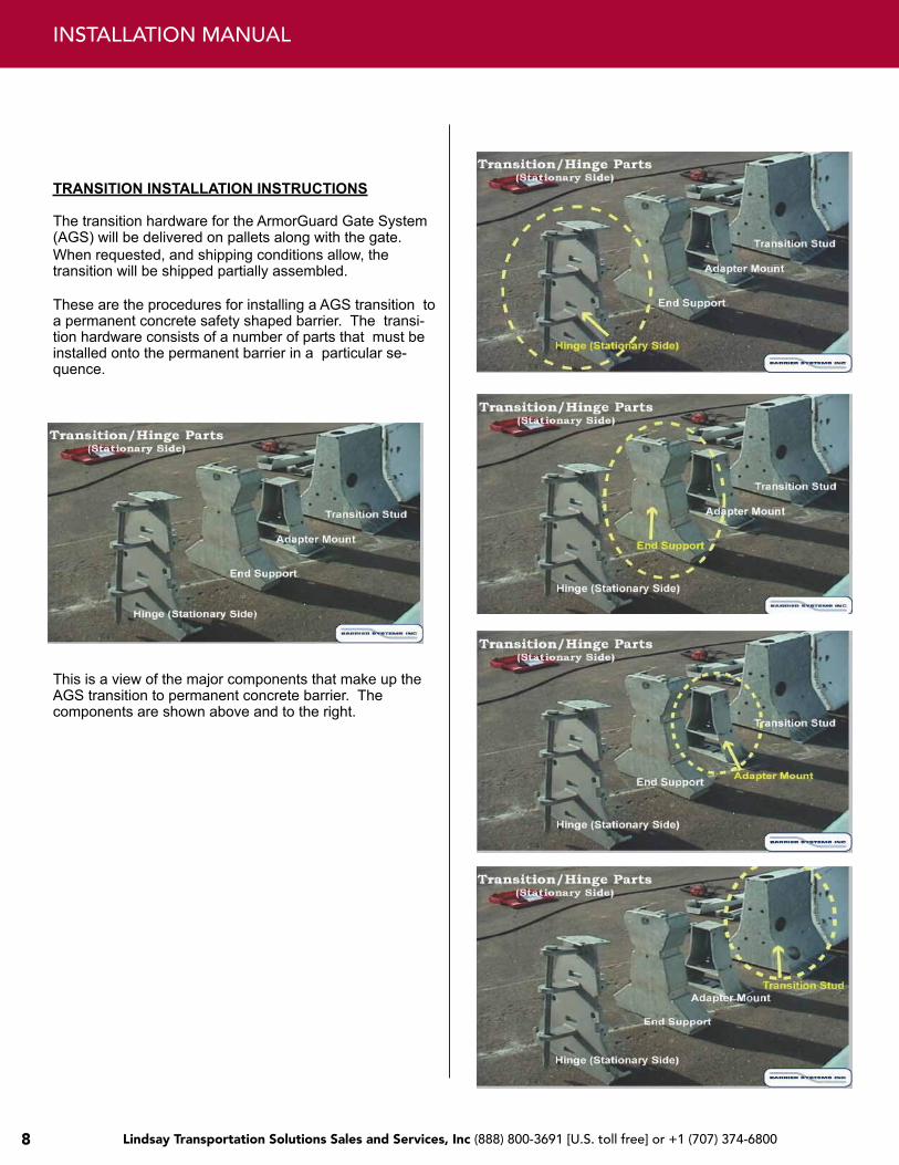
TRANSITION INSTALLATION INSTRUCTIONS
The transition hardware for the ArmorGuard Gate System (AGS) will be delivered on pallets along with the gate. When requested, and shipping conditions allow, the transition will be shipped partially assembled.
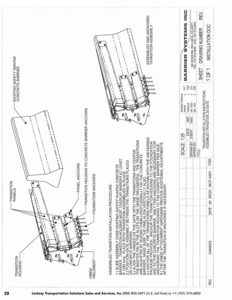
These are the procedures for installing a AGS transition to a permanent concrete safety shaped barrier. The transi-tion hardware consists of a number of parts that must be installed onto the permanent barrier in a particular se-quence.
This is a view of the major components that make up the AGS transition to permanent concrete barrier. The components are shown above and to the right.
Lindsay Transportation Solutions Sales and Services, Inc (888) 800-3691 [U.S. toll free] or +1 (707) 374-6800 9
aRMoRGUaRD® PERMaNENT GaTE
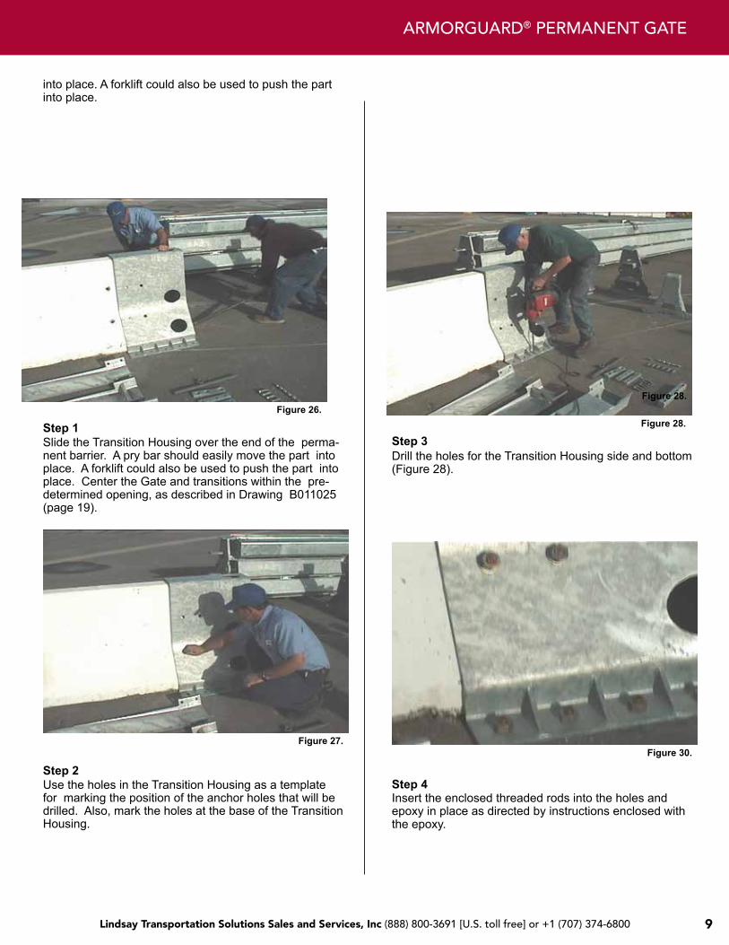
Figure 26.
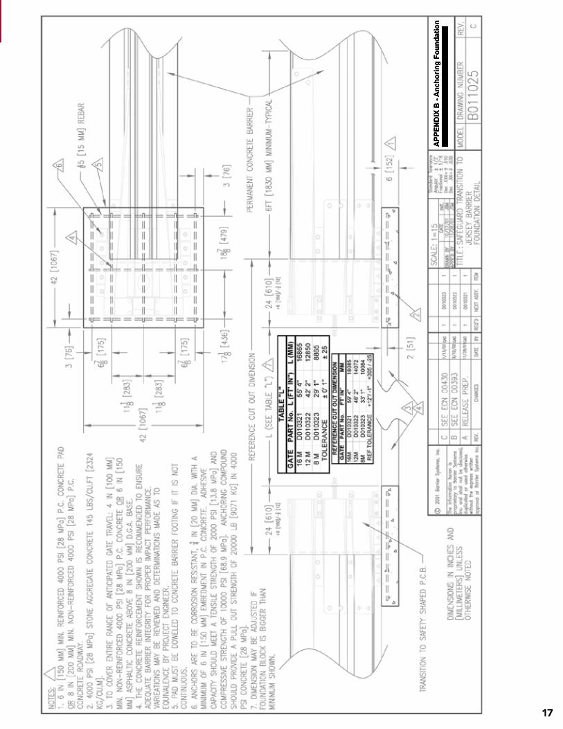
Step 1 Slide the Transition Housing over the end of the perma-nent barrier. A pry bar should easily move the part into place. A forklift could also be used to push the part into place. Center the Gate and transitions within the pre-determined opening, as described in Drawing B011025 (page 19).
Figure 27.
Step 3
Step 4
Figure 28.
into place. A forklift could also be used to push the part into place.
Step 2 Use the holes in the Transition Housing as a template for marking the position of the anchor holes that will be drilled. Also, mark the holes at the base of the Transition Housing.
Figure 28.
Drill the holes for the Transition Housing side and bottom (Figure 28).
Figure 30.
Insert the enclosed threaded rods into the holes and epoxy in place as directed by instructions enclosed with the epoxy.
Lindsay Transportation Solutions Sales and Services, Inc (888) 800-3691 [U.S. toll free] or +1 (707) 374-6800 Lindsay Transportation Solutions Sales and Services, Inc (888) 800-3691 [U.S. toll free] or +1 (707) 374-680010
INSTaLLaTIoN MaNUaL
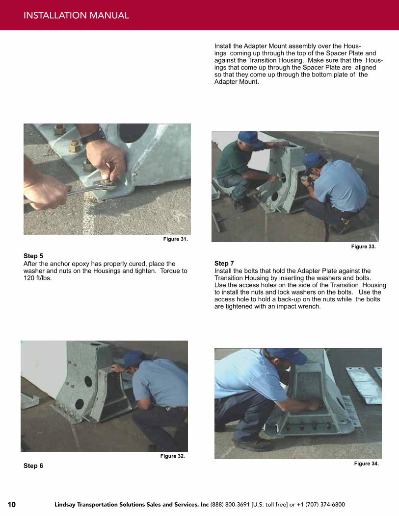
Figure 31.
Figure 32.
Step 7 Step 5 After the anchor epoxy has properly cured, place the washer and nuts on the Housings and tighten. Torque to 120 ft/lbs.
Step 6
Install the Adapter Mount assembly over the Hous-ings coming up through the top of the Spacer Plate and against the Transition Housing. Make sure that the Hous-ings that come up through the Spacer Plate are aligned so that they come up through the bottom plate of the Adapter Mount.
Figure 33.
Install the bolts that hold the Adapter Plate against the Transition Housing by inserting the washers and bolts. Use the access holes on the side of the Transition Housing to install the nuts and lock washers on the bolts. Use the access hole to hold a back-up on the nuts while the bolts are tightened with an impact wrench.
Figure 34.
Lindsay Transportation Solutions Sales and Services, Inc (888) 800-3691 [U.S. toll free] or +1 (707) 374-6800 11
aRMoRGUaRD® PERMaNENT GaTE
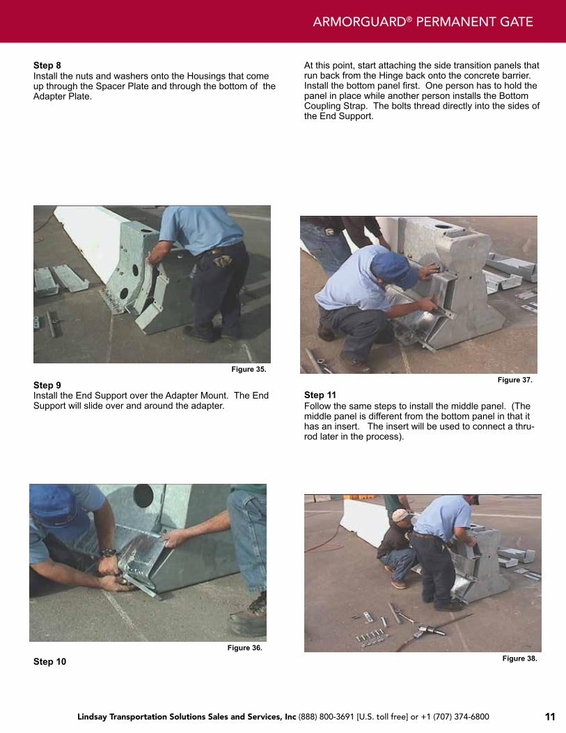
Figure 35.
Step 9 Install the End Support over the Adapter Mount. The End Support will slide over and around the adapter.
Figure 36.
Step 8 Install the nuts and washers onto the Housings that come up through the Spacer Plate and through the bottom of the Adapter Plate.
Step 10
At this point, start attaching the side transition panels that run back from the Hinge back onto the concrete barrier. Install the bottom panel first. One person has to hold the panel in place while another person installs the Bottom Coupling Strap. The bolts thread directly into the sides of the End Support.
Figure 37.
Step 11 Follow the same steps to install the middle panel. (The middle panel is different from the bottom panel in that it has an insert. The insert will be used to connect a thru-rod later in the process).
Figure 38.
Lindsay Transportation Solutions Sales and Services, Inc (888) 800-3691 [U.S. toll free] or +1 (707) 374-6800 Lindsay Transportation Solutions Sales and Services, Inc (888) 800-3691 [U.S. toll free] or +1 (707) 374-680012
INSTaLLaTIoN MaNUaL
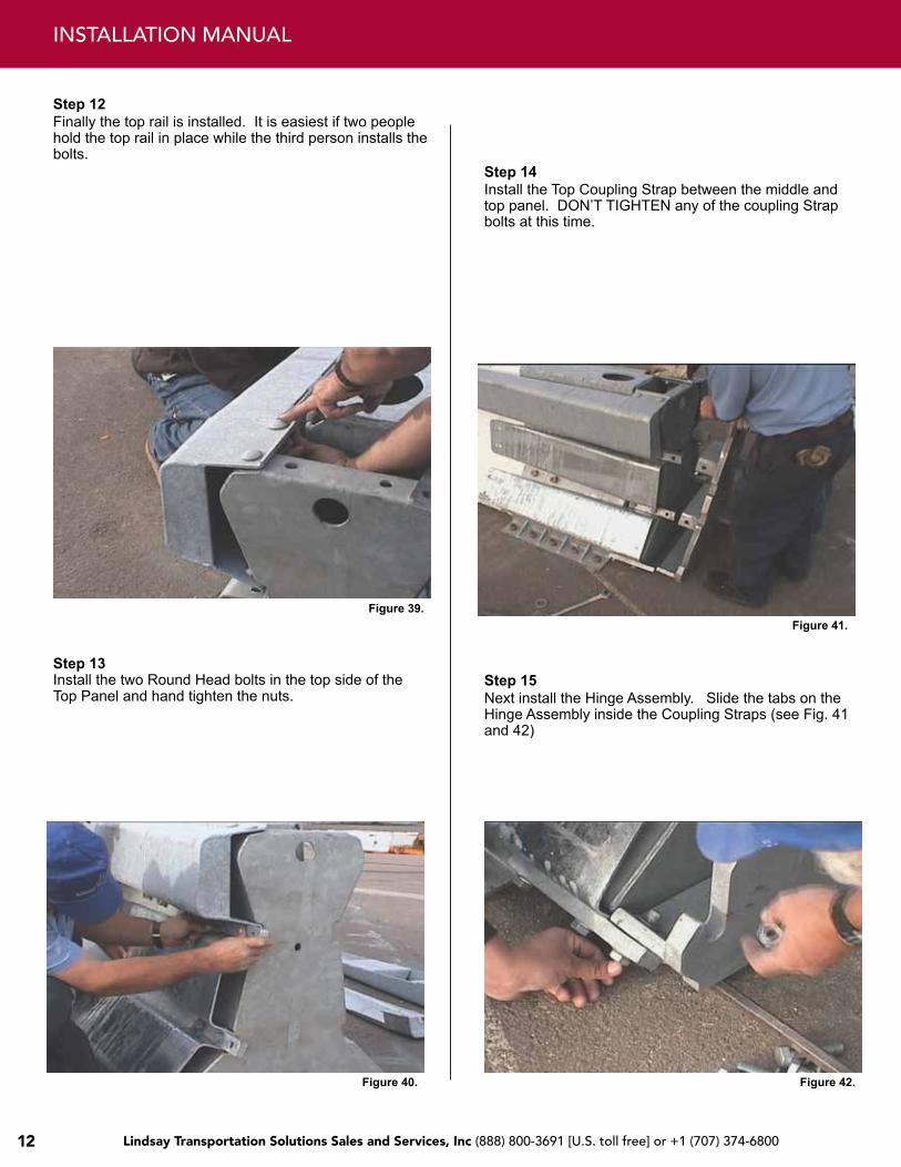
Step 12 Finally the top rail is installed. It is easiest if two people hold the top rail in place while the third person installs the bolts.
Figure 39.
Step 13 Install the two Round Head bolts in the top side of the Top Panel and hand tighten the nuts.
Step 14 Install the Top Coupling Strap between the middle and top panel. DON’T TIGHTEN any of the coupling Strap bolts at this time.
Figure 41.
Step 15 Next install the Hinge Assembly. Slide the tabs on the Hinge Assembly inside the Coupling Straps (see Fig. 41 and 42)
Figure 40. Figure 42.
Lindsay Transportation Solutions Sales and Services, Inc (888) 800-3691 [U.S. toll free] or +1 (707) 374-6800 13
aRMoRGUaRD® PERMaNENT GaTE
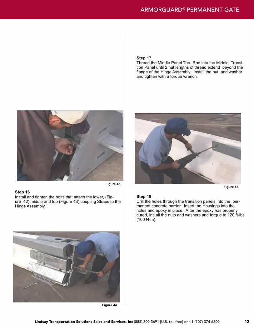
Figure 43.
Step 16 Install and tighten the bolts that attach the lower, (Fig-ure 42) middle and top (Figure 43) coupling Straps to the Hinge Assembly.
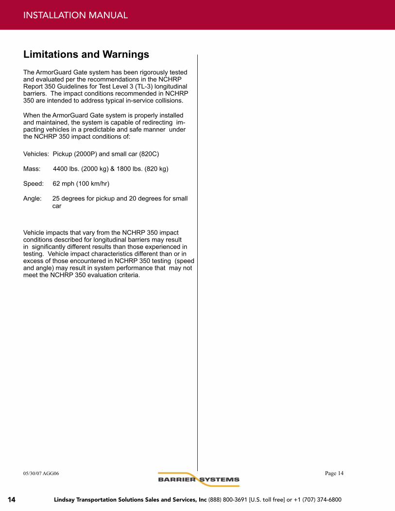
Step 17
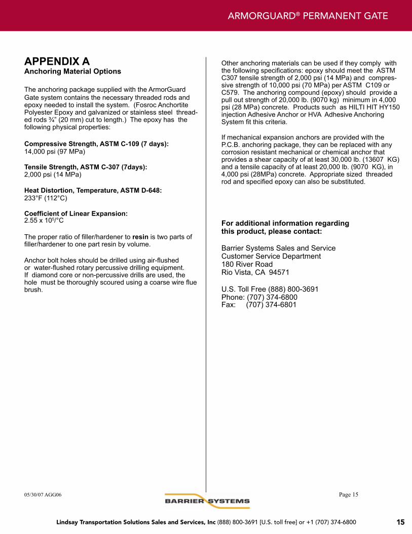
Step 18
Figure 44.
Thread the Middle Panel Thru Rod into the Middle Transi-tion Panel until 2 nut lengths of thread extend beyond the flange of the Hinge Assembly. Install the nut and washer and tighten with a torque wrench.
Figure 45.
Drill the holes through the transition panels into the per-manent concrete barrier. Insert the Housings into the holes and epoxy in place. After the epoxy has properly cured, install the nuts and washers and torque to 120 ft-lbs (160 N-m).
Lindsay Transportation Solutions Sales and Services, Inc (888) 800-3691 [U.S. toll free] or +1 (707) 374-6800 Lindsay Transportation Solutions Sales and Services, Inc (888) 800-3691 [U.S. toll free] or +1 (707) 374-680014
INSTaLLaTIoN MaNUaL
Limitations and Warnings The ArmorGuard Gate system has been rigorously tested and evaluated per the recommendations in the NCHRP Report 350 Guidelines for Test Level 3 (TL-3) longitudinal barriers. The impact conditions recommended in NCHRP 350 are intended to address typical in-service collisions.
When the ArmorGuard Gate system is properly installed and maintained, the system is capable of redirecting im-pacting vehicles in a predictable and safe manner under the NCHRP 350 impact conditions of:
Vehicles: Pickup (2000P) and small car (820C)
Mass: 4400 lbs. (2000 kg) & 1800 lbs. (820 kg)
Speed: 62 mph (100 km/hr)
Angle: 25 degrees for pickup and 20 degrees for small car
Vehicle impacts that vary from the NCHRP 350 impact conditions described for longitudinal barriers may result in significantly different results than those experienced in testing. Vehicle impact characteristics different than or in excess of those encountered in NCHRP 350 testing (speed and angle) may result in system performance that may not meet the NCHRP 350 evaluation criteria.
05/30/07 AGG06 Page 14
Lindsay Transportation Solutions Sales and Services, Inc (888) 800-3691 [U.S. toll free] or +1 (707) 374-6800 15
aRMoRGUaRD® PERMaNENT GaTE
For additional information regarding this product, please contact:
Barrier Systems Sales and Service Customer Service Department 180 River Road Rio Vista, CA 94571
U.S. Toll Free (888) 800-3691 Phone: (707) 374-6800 Fax: (707) 374-6801
APPENDIX A Anchoring Material Options
The anchoring package supplied with the ArmorGuard Gate system contains the necessary threaded rods and epoxy needed to install the system. (Fosroc Anchortite Polyester Epoxy and galvanized or stainless steel thread-ed rods ¾” (20 mm) cut to length.) The epoxy has the following physical properties:
Compressive Strength, ASTM C-109 (7 days): 14,000 psi (97 MPa)
Tensile Strength, ASTM C-307 (7days): 2,000 psi (14 MPa)
Heat Distortion, Temperature, ASTM D-648: 233°F (112°C)
Coefficient of Linear Expansion: 2.55 x 10⁵/°C
The proper ratio of filler/hardener to resin is two parts of filler/hardener to one part resin by volume.
Anchor bolt holes should be drilled using air-flushed or water-flushed rotary percussive drilling equipment. If diamond core or non-percussive drills are used, the hole must be thoroughly scoured using a coarse wire flue brush.
Other anchoring materials can be used if they comply with the following specifications: epoxy should meet the ASTM C307 tensile strength of 2,000 psi (14 MPa) and compres-sive strength of 10,000 psi (70 MPa) per ASTM C109 or C579. The anchoring compound (epoxy) should provide a pull out strength of 20,000 lb. (9070 kg) minimum in 4,000 psi (28 MPa) concrete. Products such as HILTI HIT HY150 injection Adhesive Anchor or HVA Adhesive Anchoring System fit this criteria.
If mechanical expansion anchors are provided with the P.C.B. anchoring package, they can be replaced with any corrosion resistant mechanical or chemical anchor that provides a shear capacity of at least 30,000 lb. (13607 KG) and a tensile capacity of at least 20,000 lb. (9070 KG), in 4,000 psi (28MPa) concrete. Appropriate sized threaded rod and specified epoxy can also be substituted.
05/30/07 AGG06 Page 15
Lindsay Transportation Solutions Sales and Services, Inc (888) 800-3691 [U.S. toll free] or +1 (707) 374-6800 Lindsay Transportation Solutions Sales and Services, Inc (888) 800-3691 [U.S. toll free] or +1 (707) 374-680016
INSTaLLaTIoN MaNUaL
APPENDIX B Anchoring Foundation and Barrier Cutout
Placement and installation of the ArmorGuard Gate system must be accomplished in accordance with the guidelines and recommendations set forth in the “AASHTO Roadside Design Guide,” FHWA memoranda and other state and local standards.
Foundation Detail, Transition to New Jersey Shaped P.C.B. Drawing # B011025 ………………………… Page 17
For additional information regarding this product, please contact:
Barrier Systems Sales and Service Customer Service Department 180 River Road Rio Vista, CA 94571
U.S. Toll Free (888) 800-3691 Phone: (707) 374-6800 Fax: (707) 374-6801
Lindsay Transportation Solutions Sales and Services, Inc (888) 800-3691 [U.S. toll free] or +1 (707) 374-6800 17
Lindsay Transportation Solutions Sales and Services, Inc (888) 800-3691 [U.S. toll free] or +1 (707) 374-6800 Lindsay Transportation Solutions Sales and Services, Inc (888) 800-3691 [U.S. toll free] or +1 (707) 374-680018
INSTaLLaTIoN MaNUaL
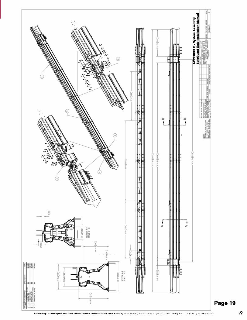
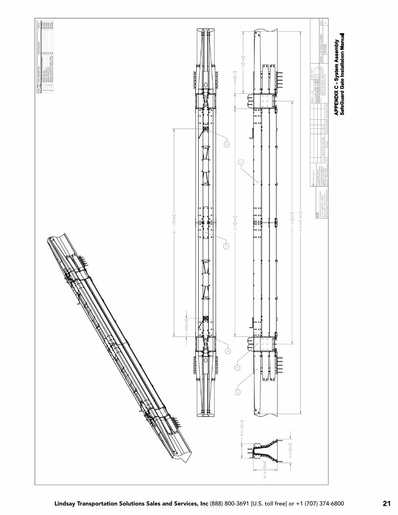
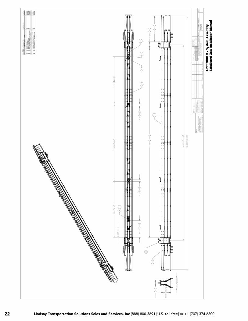
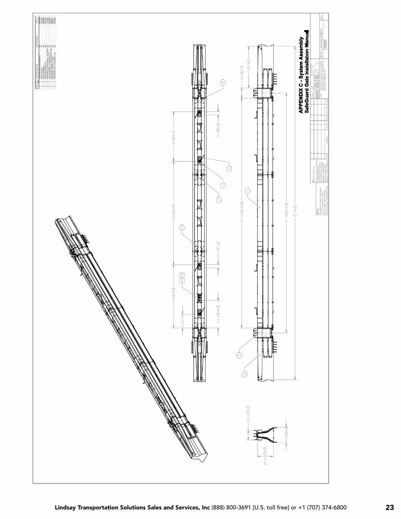
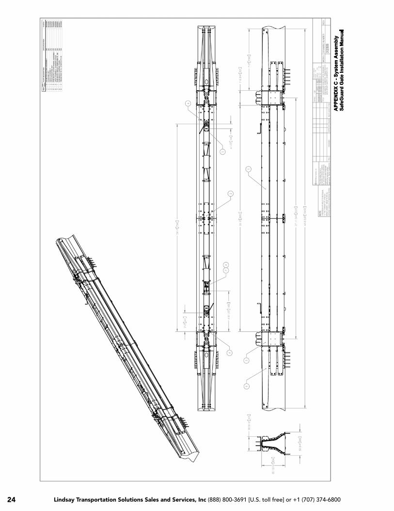
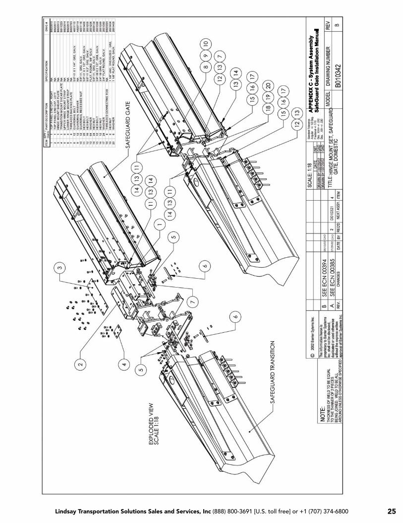
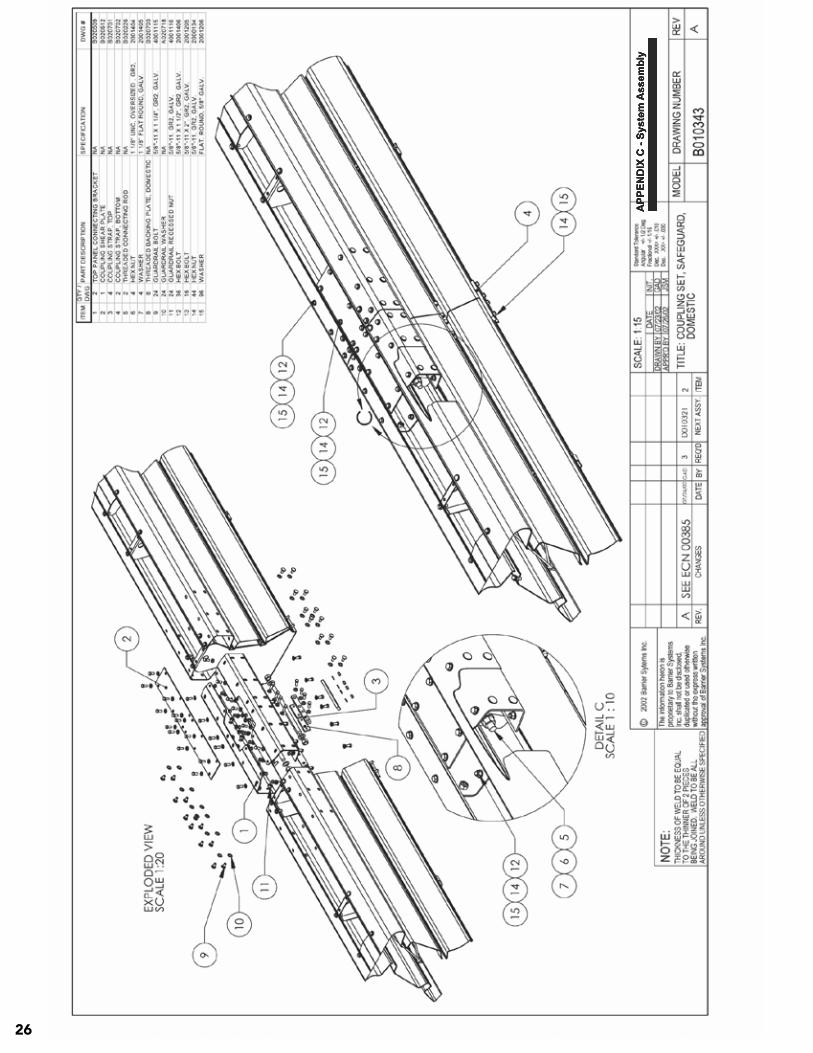
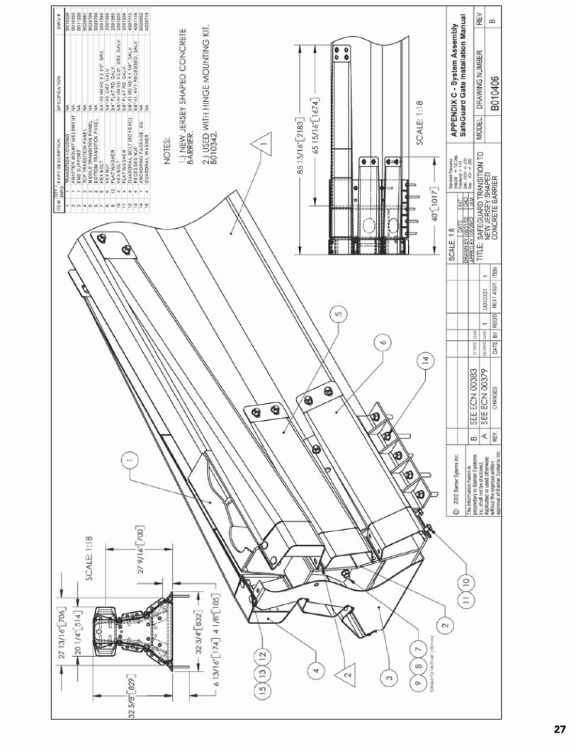
APPENDIX C System Assembly Drawings
Placement and installation of the ArmorGuard Gate system must be accomplished in accordance with the guidelines and recommendations set forth in the “AASHTO Roadside Design Guide,” FHWA memoranda and other state and local standards.
16-Meter Manual Assembly Drawing # D010321 ………………………… Page 19
12-Meter Manual Assembly Drawing # D010322 ………………………… Page 20
8-Meter Manual Assembly Drawing # D010323 ………………………… Page 21
16-Meter Pneumatic Assembly Drawing # D020703 ………………………… Page 22
12-Meter Pneumatic Assembly Drawing # D020837 ………………………… Page 23
8-Meter Pneumatic Assembly Drawing # D020838 ………………………… Page 24
Hinge Mount Set Drawing # B010342 ………………………… Page 25
Coupling Set Drawing # B010343 ………………………… Page 26
Transition to New Jersey Shaped Barrier Assembly Drawing # B010406 ………………………… Page 27
Assembled Transition ………………………. Page 28
For additional information regarding this product, please contact:
Barrier Systems Sales and Service Customer Service Department 180 River Road Rio Vista, CA 94571
U.S. Toll Free (888) 800-3691 Phone: (707) 374-6800 Fax: (707) 374-6801
05/30/07 AGG06 Page 17 Page 18
Lindsay Transportation Solutions Sales and Services, Inc (888) 800-3691 [U.S. toll free] or +1 (707) 374-6800 19

Lindsay Transportation Solutions Sales and Services, Inc (888) 800-3691 [U.S. toll free] or +1 (707) 374-6800 Lindsay Transportation Solutions Sales and Services, Inc (888) 800-3691 [U.S. toll free] or +1 (707) 374-680020
Lindsay Transportation Solutions Sales and Services, Inc (888) 800-3691 [U.S. toll free] or +1 (707) 374-6800 21
Lindsay Transportation Solutions Sales and Services, Inc (888) 800-3691 [U.S. toll free] or +1 (707) 374-6800 Lindsay Transportation Solutions Sales and Services, Inc (888) 800-3691 [U.S. toll free] or +1 (707) 374-680022
Lindsay Transportation Solutions Sales and Services, Inc (888) 800-3691 [U.S. toll free] or +1 (707) 374-6800 23
Lindsay Transportation Solutions Sales and Services, Inc (888) 800-3691 [U.S. toll free] or +1 (707) 374-6800 Lindsay Transportation Solutions Sales and Services, Inc (888) 800-3691 [U.S. toll free] or +1 (707) 374-680024
Lindsay Transportation Solutions Sales and Services, Inc (888) 800-3691 [U.S. toll free] or +1 (707) 374-6800 25
Lindsay Transportation Solutions Sales and Services, Inc (888) 800-3691 [U.S. toll free] or +1 (707) 374-6800 Lindsay Transportation Solutions Sales and Services, Inc (888) 800-3691 [U.S. toll free] or +1 (707) 374-680026
Lindsay Transportation Solutions Sales and Services, Inc (888) 800-3691 [U.S. toll free] or +1 (707) 374-6800 27
Lindsay Transportation Solutions Sales and Services, Inc (888) 800-3691 [U.S. toll free] or +1 (707) 374-6800 Lindsay Transportation Solutions Sales and Services, Inc (888) 800-3691 [U.S. toll free] or +1 (707) 374-680028
Lindsay Transportation Solutions Sales and Services, Inc (888) 800-3691 [U.S. toll free] or +1 (707) 374-6800 29
For additional information regarding this product, please contact:
Barrier Systems Sales and Service Customer Service Department 180 River Road Rio Vista, CA 94571
U.S. Toll Free (888) 800-3691 Phone: (707) 374-6800 Fax: (707) 374-6801
Page 29
APPENDIX D Maintenance
Periodic Maintenance
The ArmorGuard Gate System has been designed to minimize the need for periodic maintenance. The only periodic maintenance items that need to be ad-dressed are as follows:
• Apply grease (Chevron EP NLGI 2 grease or equivalent) to the zerk fittings on the caster wheels at least annually.
• If the system is supplied with an on-board air tank, the air pressure should be checked at least monthly to ensure that adequate pressure is available to operate the system.
General Inspection and Maintenance
Drive-by Inspection
Drive-by type inspections should be performed at least monthly. The purpose of the drive-by inspec-tion is to observe for the following characteristics:
• Any evidence of vehicle impacts. • Structural damage. • Loose or out of place components. • Excessive debris build-up that would not
allow the system to be operated.
If any of these conditions are observed, a walk-up inspection is required.
Walk-up Inspections
Walk-up inspections should be conducted at least annually and whenever deemed appropriate from a drive-by inspection. A walk-up inspection should consist of the following items:
• Structural components – Conduct an inspec-tion of all structural assemblies to ensure that all components are structurally sound, properly connected and there are no loose fasteners or damaged components. The hinge pins should be in position and free to move and the hinge covers properly fitted and connected. Any components observed to be non-conforming to the manufac-turer’s drawings should be replaced or repaired.
• Operating systems – Raise, hold, and lower the system in accordance with the operat-ing instructions and ensure that the hinge covers, hinge pins, valves, pneumatic system, casters and other functional com-ponents operate in the proper manner. Any components observed to be deficient should be repaired or replaced in accor-dance with the manufacturer’s instructions.
• General cleaning – The area around and within the internal and external operat-ing area should be kept free of debris that could affect either the impact performance or restrict the ability to open or close the system when needed.
05/30/07 AGG06 Page 18

Lindsay Transportation Solutions Sales and Services, Inc (888) 800-3691 [U.S. toll free] or +1 (707) 374-6800 Lindsay Transportation Solutions Sales and Services, Inc (888) 800-3691 [U.S. toll free] or +1 (707) 374-680030
Page Left Intentionally Blank

Lindsay Transportation Solutions Sales and Services, Inc (888) 800-3691 [U.S. toll free] or +1 (707) 374-6800 31
Page Left Intentionally Blank

Lindsay Transportation Solutions Sales and Services, Inc 180 River Road • Rio Vista, Ca 94571 • +1 707.374.6800 U.S. Toll Free: 888.800.3691 • www.barrriersystemsinc.com
Installation manual details for the ArmorGuard Gate System are subject to change without notice to reflect improvements and upgrades.additional information is available from Barrier Systems Sales and Service © Lindsay Transportation Solutions
aRMoRGUaRD PERM GaTE 061207