powermaster medium duty barrier gate operator · for barrier gate operating systems safety is...
TRANSCRIPT

Installation Manual
UL 325 AND UL 991 LISTED
MEDIUM DUTY BARRIER GATE OPERATORUL
R
PowerMaster
2
MODEL “MBG” MEDIUM DUTY BARRIER GATE OPERATOR Important Safety Information………………………………............…...……3 System Designer Safety Instructions……………………….…....…...4 Installer Safety Instructions…………………………………….....…. ..….…5 Installation Notes ……………………………………….................…….6 End User Safety Warnings ………………………………….….……....8 Installation & Setup Procedure Before Installing Operator……………………………..………..……..11
Installation of Mounting Pipe………………………………………….12 Installation of Power Head………………………………..…..............14 Installation of Barrier Arm…………………………………...…..........15 Electrical Connections…………………………...……………………….15 Left Hand/Right Hand Conversions…………………………………...17
Manual Operation……………………………………...………………....18 Limit Adjustment Procedure………………………………..…………19 Master/Slave Operation………………………………………………...20 Connection of a 3 Button Station……………………………………..21 Radio Control Installation………………………………….…………..21 Timer To Close…………………………………….……………………..22 Installation of Edge Sensor or Photo Eyes……………………….…22 Loop Detector Systems and Installation Loop Layout Diagram…………………………………………………...23 Standard Loop Layouts…………………………….…........................24 Loop Installation…………………………………………………………24 Cutting The Required Groove…………………………......................25 Loop Connections……………………………………………………….26 Installer Information…………………………………………………… .27 Wiring Diagram………………………………………………….……….28 Notes/Maintenance Log………………………………….……………....29 Warranty……………………………..……………………………………...30
TABLE OF CONTENTS

3
III MMM PPP OOO RRR TTT AAA NNN TTT !!!
FOR BARRIER GATE OPERATING SYSTEMS SAFETY IS EVERYONE’S BUSINESS
Automatic gate operators provide convenience and security to users. However, because these machines can produce high levels of force, it is important that all gate operator system designers, installers, and end users be aware of the potential hazards associated with improperly designed, installed, or maintained systems. Keep in mind that the gate operator is a component part of a total gate operating system.
The following information contains various safety precautions and warnings for the system designer, installer and end user. These instructions provide an overview of the importance of safe design, installation, and use.
Warnings are identified with the ▲ symbol. This symbol will identify some of the conditions that can result in serious injury or death. Take time to carefully read and follow these precautions and other important information provided to help ensure safe system design, installation and use.
▲ WARNING: Gate operators are only one part of a TOTAL GATE OPERATING SYSTEM. It is the responsibility of purchaser, designer, and installer to ensure that the total system is safe for its intended use. All secondary entrapment safety devices must be RECOGNIZED by U/L to ensure the safety of the complete operating system.
4
SYSTEM DESIGNER SAFETY INSTRUCTIONS
▲ 1. Familiarize yourself with the precautions and warnings for the installer. Users are relying on your design to provide a safe installation. The installation should have an entrapment protection system installed such as photoelectric sensors or an electric edge.
▲ 2. When designing a system that will be entered from a
highway or main thoroughfare be sure the system is placed far enough away from the road to eliminate traffic backup. Distance from the road, size of the gate, usage levels, and gate cycle/speed must be considered to eliminate potential traffic hazards.
▲ 3. Design the gate system so a person cannot be
trapped between the arm and any other fixed structure. All rigid objects must be at least 2 feet from gate arm.
2 FEET

5
INSTALLER SAFETY INSTRUCTIONS
BEFORE INSTALLATION
▲ 1. Check to see that the operator is proper for this type and size of opening and its frequency of use. If you are not sure, consult factory.
▲ 2. Check to see that there are no structures
adjacent to the area, which may pose a risk of entrapment when gate is opening or closing.
▲ 3. Safety equipment such as electric edges or
photocell sensors must be installed to provide personnel, equipment, and property protection. For assistance in selecting the correct type of safety equipment, consult the factory.
▲ 4. You must install a pushbutton control or key
switch to allow for normal operation of the gate if the automatic controls do not work. Locate the pushbutton or key switch and small warning placard within sight of the gate in a secured area at least 10 feet or more from the gate and fence to keep users away from the moving gate and fence.
▲ 5. Outdoor or easily accessed gate controls should
be of the security type to prohibit unauthorized use.
6
DURING INSTALLATION
▲ 1. Be aware of all moving parts and avoid close proximity to any pinch points.
▲ 2. Disconnect power at the control panel before making
any electric service connections. Connection location for controls and safety equipment can be found on the wiring diagram, and in this manual.
▲ 3. Locate the controls at least 10 feet from the moving
gate so that the user can observe the gate operation, but is not able to come in contact with the gate while operating the controls.
10 FEET

7
AFTER INSTALLATION
▲ You are responsible for ensuring that the end user understands the basic operations and safety systems of the unit, including the proper way to engage and manually operate the unit.
▲ Point out that the safety instructions in brochure are the responsibility of the end user, and then LEAVE A COPY OF THIS BROCHURE WITH THE END USER
8
END-USER SAFETY WARNINGS
Be sure you’ve been fully instructed on the sequence of operation for your specific gate system(s). Keep the gate properly maintained and have a qualified service person make repairs.
▲ 1. Be sure the following safety instructions are
distributed to all persons authorized to use your gate.
▲ 2. KEEP GATEWAY CLEAR AT ALL TIMES. Your
automatic gate is not for pedestrian use. No one should ever cross the path of the moving gate.

9
▲ 3. DO NOT allow children to play near your gate, or to operate the gate.
▲ 4. DO NOT operate your gate system unless you can see it when the gate moves.
▲ 5. Be sure a pushbutton or key switch has been
installed for manual electric operation in the event your radio or card does not work. Any mounted control station should be located a minimum of 10 feet from the gate so the gate cannot be touched. Any pushbutton located in a building should be installed within sight of the gate.
▲ 6. DO NOT operate any controls without watching the
movement of the gate.
▲ 7. Be sure the gate arm DOES NOT come within 2 feet of any rigid object, therefore causing an entrapment situation.
10
2 FEET
▲ 8. If your gate closes automatically, loop detectors
should be installed to detect the presence of a vehicle.
▲ 9. If a contact or non-contact safety system has been installed check for proper operation at least once per month. If these functions are observed to operate improperly, discontinue use and have it serviced immediately!
▲ 10. To ensure safe operation of this equipment, you
must read this safety manual and keep it for reference.
MANUAL OPERATION ▲ . Please refer to page 18 for Manual Operation
Instructions.

11
INSTALLATION INSTRUCTIONS
WARNING: DO NOT APPLY POWER UNTIL TOLD TO DO SO! RISK OF ELECTRICAL SHOCK OR INJURY MAY RESULT!
BEFORE INSTALLING OPERATOR IMPORTANT:
1. Operator should always be mounted inside the gate. 2. All controls are to be mounted at least 10’ from the
gate arm.
10 FEET
2FEET
3. Allow at least 2 feet clearance from rigid objects to gate arm.
12
INSTALLATION OF MOUNTING PIPE N o t e : T h e r e a r e t w o o p t i o n s f o r t h e i n s t a l l a t i o n o f a m o u n t i n g p i p e .
1. Cement a 69” long, 1-1/2 inch pipe
(approximately 2” diameter) in the ground as shown below.
4" MIN.
33"
36"
2 FOOT DIA.
2" DIA. PIPE
ELECTRICAL SUPPLY PIPE(PER LOCAL CODE)
NOTE: A SEPARATE CONDUIT SHOULD BE USED FOR CONTROL WIRING.
Ground Level
Note: Let cement cure for two days before proceeding.
13
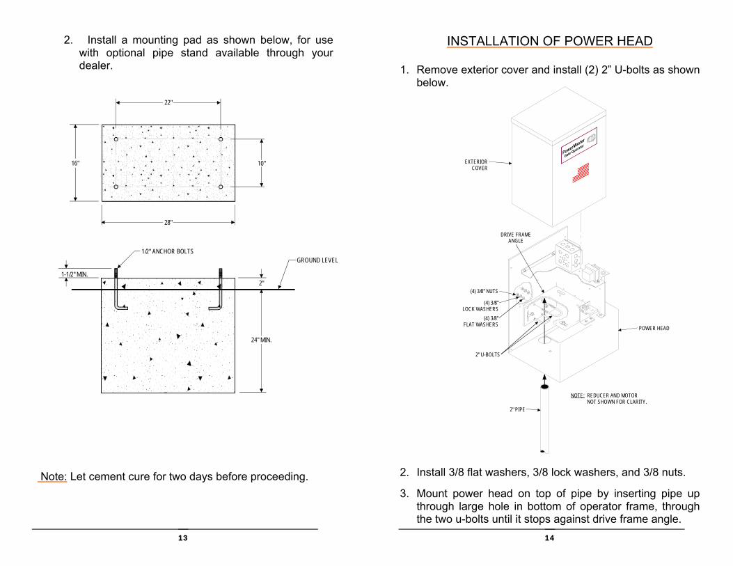
2. Install a mounting pad as shown below, for use with optional pipe stand available through your dealer.
Note: Let cement cure for two days before proceeding.
2"
24" MIN.
1/2" ANCHOR BOLTS
28"
16"
22"
10"
GROUND LEVEL
1-1/2" MIN.
14
INSTALLATION OF POWER HEAD 1. Remove exterior cover and install (2) 2” U-bolts as shown
below.
2. Install 3/8 flat washers, 3/8 lock washers, and 3/8 nuts. 3. Mount power head on top of pipe by inserting pipe up
through large hole in bottom of operator frame, through the two u-bolts until it stops against drive frame angle.
2" U-BOLTS
(4) 3/8" NUTS
(4) 3/8" LOCK WASHERS
(4) 3/8" FLAT WASHERS
DRIVE FRAMEANGLE
2" PIPE
NOTE: REDUCER AND MOTOR NOT SHOWN FOR CLARITY.
EXTERIORCOVER
POWER HEAD

15
INSTALLATION OF BARRIER ARM
1. Install arm flange on power head output shaft as shown figure below ,and secure position with ¼” square key and (2) 5/16 set screws.
2. Install (2) 2-1/2” U-bolts in arm flange as shown. 3. Install 3/8 serrated flange nuts loosely on U- bolts. 4. Insert barrier arm pipe through two U-bolts and secure the
desired position by tightening the 3/8 serrated flange nuts on the u-bolts.
2-1/2" U-BOLTS
ARM FLANGE
POWER HEADOUTPUT SHAFT
1/4" SQUARE KEY
5/16" SETSCREWS
(4) 3/8" SERRATEDFLANGE NUTS
BARRIER ARM PIPE
ELECTRICAL CONNECTIONS WARNING- DO NOT APPLY POWER UNTIL TOLD TO DO SO. RISK OF SHOCK OR INJURY MAY RESULT! NOTE: Wiring to operator must use watertight materials in accordance with local electric code. See wire gauge/distance charts for proper sizing. Master/Slave installations should have SEPARATE power supply wiring or length of wire runs
16
BLK BLK
WHT WHT
GRN GND
INSIDE UTILITY BOX,CONNECT AS SHOWN
INCOMINGPOWER115V - 1Ø
OPERATOR
UTILITY BOX
should be figured at half that shown on the chart. This unit must be grounded in accordance with N.E.C. and local codes. Before connecting the operator, use a voltmeter to determine that the electrical service is 115V. THIS OPERATOR CANNOT BE CONNECTED AT 230 VOLTS. Damage will result which is not covered under warranty.
1. Be sure power switches at source and operator are OFF. 2. Connect incoming power lines and ground wire as shown
below. Hot leg (black) to BLACK; Neutral (white) to White: Ground to GREEN
Line Voltage HP 14
AWG 12
AWG 10
AWG 8
AWG
6 AWG
115 VAC 1/2 150 250 400 500 650
LOW VOLTAGE WIREGAUGE /DISTANCE CHART
24 AWG: Up to 150' 20 AWG: 150' - 200'
250' - 1,500'
Control wiring should be run as twistedpairs. DO NOT run control wires in the
same conduit as power wires. telephonewires, or loop detector leads.
18 AWG:

17
LEFT HAND/RIGHT HAND CONVERSIONS
1. Determine the hand of the operator required for this installation by referring to the illustration below.
LEFT HAND RIGHT HAND
Note: Operators are wired for Right Hand operation at the factory.
2. Place the Yellow and Blue wires in the appropriate
positions, as shown below, for Right Hand or Left Hand operation.
Note: If operator hand is being changed, limits MUST be reset.
GREEN
BLUE
YELLOW
GRAY
GREEN
BLUE
YELLOW
GRAY
BACK OF MOTOR,LEFT HAND MOTOR CONNECTIONS
BACK OF MOTOR,RIGHT HAND MOTOR CONNECTIONS
18
MANUAL OPERATION
▲ WARNING: TURN OFF POWER SUPPLY BEFORE REMOVING COVER.
1. Remove (4) cover mounting screws and lift off top cover.
2. Remove crank pin from storage area in drive frame. See Diagram. Note: This will disengage interlock and prevent power from returning to the operator during manual operation.
3. Insert crank pin in timing pulley as shown in diagram. Rotate timing pulley with crank pin until desired position is achieved.
4. To resume powered operation, remove crank pin from timing pulley and replace in storage area on drive frame. ▲ Note: Be sure drive pin is fully inserted back into drive
frame in order to activate interlock.
5. Replace cover and secure with (4) mounting screws. 6. Turn on supply power to operator.
CRANK PIN
TIMINGPULLEY
TOP COVER

19
LIMIT ADJUSTMENT PROCEDURE
▲ WARNING: TURN OFF POWER SUPPLY BEFORE MAKING ANY ADJUSTMENTS.
1. After the operator has been installed and the Barrier Arm secured in position, rotate the arm to the horizontal position using manual crank as shown in previous section.
2. Loosen the set screw on the horizontal stop cam and rotate the cam, (counterclockwise for a Right Hand installation and clockwise for a Left Hand installation) until it just actuates the horizontal limit switch. (See diagram.) Secure this position by tightening set screw.
HORIZONTAL STOP CAM
HORIZONTAL LIMIT SWITCH
VERTICAL STOP CAM
VERTICAL LIMIT SWITCH
3. Rotate the Arm to the straight up, vertical position. Loosen the set screw on the vertical stop cam and rotate the cam, (clockwise for a Right Hand installation and counterclockwise for a Left Hand installation) until it just actuates the vertical limit switch. (See diagram.) Secure this position by tightening set screw.
4. Remove crank pin from timing pulley and replace in storage area on drive frame. Note: Be sure drive pin is fully inserted back into drive frame in order to activate interlock.
5. Turn on power, then raise and lower barrier arm using the control switch next to outlet box.
20
▲ WARNING:TURN OFF POWER BEFORE MAKING ADJUSTMENTS!!!
6. Make minor adjustments to limit cams as required to obtain the desired “OPEN” and “CLOSED” positions.
MASTER - SLAVE OPERATION
NOTE: A single unit is considered a MASTER. For MASTER-SLAVE installation, one unit must be converted to LEFT HAND operation, as shown on page 16. All units are shipped as “MASTER” from the factory.
1. Leave jumper on the MASTER operator’s circuit board in the “OFF” position. 2. Move jumper on SLAVE operator’s circuit board to the “ON” position.
ON
SLAVE
JUMPERON
SLAVE
JUMPER
MASTERPOSITION
(OFF)
SLAVEPOSITION
(ON)
3. Connect terminal #15 of MASTER unit to terminal #5 of SLAVE unit.
4. Connect terminal #16 of MASTER unit to terminal #6 of SLAVE unit. 5. Connect terminal #17 of MASTER unit to terminal #7 of SLAVE
unit.
1
2
3
4
5
6
7
89
15
16
17
AB
1
2
3
4
5
6
7
89
15
16
17
AB
MASTERTERMINAL
STRIP

21
CONNECTION OF A 3 BUTTON STATION
NOTE: All Control contacts must be NORMALLY OPEN. • Connect “STOP” button to Terminal #4. • Connect “COMMON” button to Terminal #5. • Connect “OPEN” button to Terminal #6. • Connect “CLOSE” button to Terminal #7.
RADIO CONTROL INSTALLATION
A Three or Four wire radio control receiver can be installed on this operator. See the diagrams below for the correct connections to match your installations equipment and desired functions.
NOTE: If your radio’s connecting wires are not color coded as shown, see the radio’s installation manual to determine which wires are for the normally open contacts and which require the 24 VAC Power Supply.
4 WIRERADIO
R1
R2
R3
GY
R
BK
GY
R4
N.O.CONTACT
RADIO CONTROLTERMINAL
24 VAC
USE THESE3 TERMINALSFOR 3-WIRE
RADIO CONTROL 1 2 3 4 5 A B
NOTE: The radio connections shown above are for “OPEN ONLY” operation. Therefore the “TIMER TO CLOSE” option must be activated for closing. (See next section.) If alternate “Open” -“Close” operation is desired move wire on terminal strip from terminal #2 to terminal #1.
22
TIMER TO CLOSE OPTION
The operator is equipped with a timer to close option for use with OPEN ONLY control devices such as a radio control, or card key control. The AUTO RECLOSE TIMER adjustment screw is located on the printed circuit board. The operator is shipped from the factory with this timer preset to the off position; fully counter clockwise. As the timer adjustment screw is rotated
clockwise, the closing of the gate can be delayed from 2 seconds to 60 seconds. The timer to close will only be activated whenever the gate is in the full open position.
INSTALLATION OF EDGE SENSOR OR PHOTOEYES NOTE: 24 VAC power is available between terminals A & B for devices such as photo eyes, wireless edges, etc. All safety device contacts must be NORMALLY OPEN. 1. Install edge sensor or photoelectric eye system as shown. Photocells should be installed at least 10” above the ground. NOTE: All hard wiring to safety edges must be installed so there is no threat of mechanical damage to wiring between components, when the gate is moving. NOTE: A separate pedestrian gate must be installed if there is no other entry access but the vehicular gate.
AUTOCLOSETIMER60 SEC
2 SEC
OFF
LOCATION OFAUTO CLOSE TIMERADJUSTMENT
EDGE SENSOR
PHOTOELECTRIC CELL
REFLECTOR

23
2. Electrically connect sensing system to operator terminal strip as shown below.
LOOP DETECTOR SYSTEMS AND INSTALLATION
8'4'
4'4'
4'
Road Surface
Sealant
Loop wires
Min 1"
3/16" To 1/4"Saw Slot
4'4'
8
915
FROM EDGE SENSOR ORPHOTOELECTRIC EYE
24
1. The EXIT LOOP provides a signal to open the gate when a vehicle enters the loop zone.
2. The REVERSING LOOP protects a vehicle in the loop zone
from being contacted with the gate by over riding any close signal while the gate is open, and by reversing the gate if closing.
3. The CLOSE LOOP provides a signal to close the gate when a
vehicle exits the loop.
LOOP INSTALLATION
1. Layout the desired loop locations per the diagram. The standard size chart at right will give an approximate length of wire required for various loop dimensions and number of turns required.
CAUTION: The Loop wires and Lead-in wires must be a continuous piece of wire without splices. Only use wire intended for this type of application. (Type XHHW insulation 16AWG) NOTE: Buried steel from drains or other systems may affect functioning of the loop system. Check with the factory for advice on any special installations. (1-800-243-4476).
STANDARD LOOP LAYOUTS For 36” High Detection

25
3/16" To 1/4"
1" To 2"
1" To 2"
Loop Wire(See Chart)
Lead In Wire(Twisted At 6
Turns Per Foot)
1/2" Conduit
Conduit Cut
2. Cut the required groove as shown in the diagram at left at the
locations laid out in Step #1. 3. Leave enough wire for the LEAD IN, and insert the specified
number of turns of wire into the cut grooves. (See chart page 24.)
CAUTION: Be careful not to damage the wire insulation during installation.
4. After completing the required number of loop turns, twist the ends together at the rate of 6 turns per foot to form the LEAD-IN.
5. Seal the LEAD-IN wire in the conduit to prevent moisture
seepage into the conduit.
6. Fill over the loop wires in the groove with a recommended loop sealant. Contact your distributor for available sealants.
7. Mount the loop detector in the operator and connect the wire
loop.
26
8. Connect loop detector to the control board as shown in the following diagrams. Note: The following diagrams show single loop connections. For multiple loop connections consult the loop detector’s instruction manual, or call the Power Master Technical line at 1-800-243-4476.
1. The EXIT LOOP provides a signal to open the gate when a vehicle enters the loop zone.
VORRP
Not Used
BLBK
WH
Y
GR
BRGY
TO DRIVEWAYLOOP
NOTE: TWIST LEADS APPOX. 6 TURNS PER FOOT.
EXIT LOOP CONNECTION
1 2 3 4 5 A B
2. The REVERSING LOOP protects a vehicle in the loop zone from being contacted with the gate by over riding any close signal while the gate is open, and by reversing the gate if closing.
VORRP
Not Used
BL
BK
WH
YGR
BRGY
TO DRIVEWAYLOOP
REVERSING LOOP CONNECTION
NOTE: TWIST LEADS APPOX. 6 TURNS PER FOOT.
1 2 3 4 5 6 7 8 9 A B

27
3. The CLOSE LOOP provides a signal to close the gate
when a vehicle exits the loop.
VBLYP
Not Used
OR
BK
WH
RGR
BRGY
TO DRIVEWAYLOOP
NOTE: TWIST LEADS APPOX. 6 TURNS PER FOOT.
1 2 3 4 5 6 7 8 9 A B
CLOSE LOOP CONNECTION
WARNING LOOP DETECTOR MUST BE PROGRAMMED TO ACTIVATE OPERATOR WHEN VEHICLE LEAVES LOOP.(SEE LOOP DETECTOR INSTRUCTIONS OR CALL FACTORY TECHNICALHELP AT 1-800-243-4476)
28

29
Maintenance Log
____________________________________________________________________________________________________________________________________________________________________________________________________________________________________________________________________________________________________________________________________________________________________________________________________________________________________________________________________________________________________________________________________________________________________________________________________________________________________________________________________________________________________________________________________________________________________________________________________________________________________________________________________________________________________________________________________________________________________________________________________________________________________________________________________________________________________________________________________________________________________________________________________________________________________________________________________________________________________________________________________________________________________________________________________________________________________
30
_____________________________________________ Notes
____________________________________________________________________________________________________________________________________________________________________________________________________________________________________________________________________________________________________________________________________________________________________________________________________________________________________________________________________________________________________________________________________________________________________________________________________________________________________________________________________________________________________________________________________________________________________________________________________________________________________________________________
Registration Information
Model MBG Location Installed: Date Installed____________ Address ___________________ Serial # ________________ Address ____________________ Address ____________________
Installer’s Information
Company Name ______________________________________ Company Address ____________________________________ Company Address ____________________________________ Company Address ____________________________________ Company Telephone # _________________________________ Company Contact _____________________________________

31
PowerMaster Limited 5 Year Warranty
PowerMaster warrants all gate operators to be free of defects in materials and workmanship for a period of Five (5) years from date of purchase. If any part is found to be defective during this period, new parts will be furnished free of charge. Failure of this product due to misuse, improper installation, alterations, vandalism, or lack of maintenance is not covered under this warranty, and voids any other implied warranties herein. PowerMaster is not responsible for any labor charges incurred in connection with the installation of warranted parts. In order to activate this warranty, the registration form on opposite page MUST be completed and returned within THIRTY CALENDER DAYS FROM DATE OF PURCHASE VIA CERTIFIED MAIL. If registration is not activated, a one year warranty will apply.
32
Model MBG
Date Installed____________
Serial # ________________
Location Installed:
Address: ___________________
Address: ___________________
Address: ___________________
Installer’s Information
Company Name _____________________ Company Telephone # ______________
Company Address ___________________ Company Contact _________________
Company Address ___________________
Company Address ___________________