armstrong mechanical purger installation and operation · pdf filearmstrong mechanical purger...
TRANSCRIPT

Armstrong Mechanical Purger Installation and Operation ManualModel XR1500


Installation and Set Up Overview
Installation Instructions 1
Connecting the Purger to the Refrigerated System 2
Piping Tips 5
Purge Connections for Condensers 5
Purge Connections for Receiver 5
Installation Notes 6
Start Up Procedures 8
Limited Warranty and Remedy 9
Warning:These installation, operation and technical instructions should be used by experienced personnel as a guide to insure that the Armstrong XR1500 Mechanical Purger functions in a correct manner. Selection or installation of equipment should always be accompanied by competent technical assistance. We encourage you to contact your local representative or the Armstrong Factory if further information is required.
Page 1
InstallationXR1500 Mechanical Purger
Warning:All installation and service performed on the Armstrong Purger should be performed by competent personnel. Observe all safety precautions plus wear protective clothing and eye protection at all times.
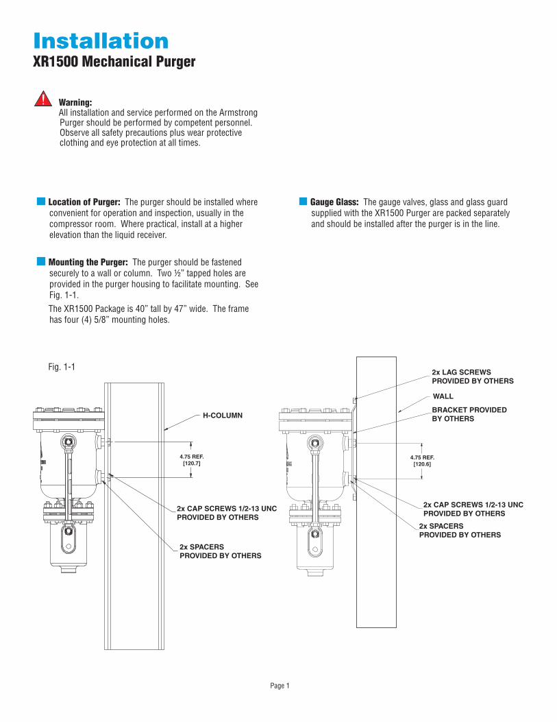
Fig. 1-1
Location of Purger: The purger should be installed where convenient for operation and inspection, usually in the compressor room. Where practical, install at a higher elevation than the liquid receiver.
Mounting the Purger: The purger should be fastened securely to a wall or column. Two ½” tapped holes are provided in the purger housing to facilitate mounting. See Fig. 1-1. The XR1500 Package is 40” tall by 47” wide. The frame has four (4) 5/8” mounting holes.
Gauge Glass: The gauge valves, glass and glass guard supplied with the XR1500 Purger are packed separately and should be installed after the purger is in the line.
2x LAG SCREWS PROVIDED BY OTHERS
WALL
BRACKET PROVIDED BY OTHERS
2x CAP SCREWS 1/2-13 UNC PROVIDED BY OTHERS
2x SPACERS PROVIDED BY OTHERS
4.75 REF. [120.6]
4.75 REF. [120.7]
2x CAP SCREWS 1/2-13 UNC PROVIDED BY OTHERS
2x SPACERS PROVIDED BY OTHERS
H-COLUMN
Page 2
Installation ProcedureConnecting the Purger to the Refrigeration System
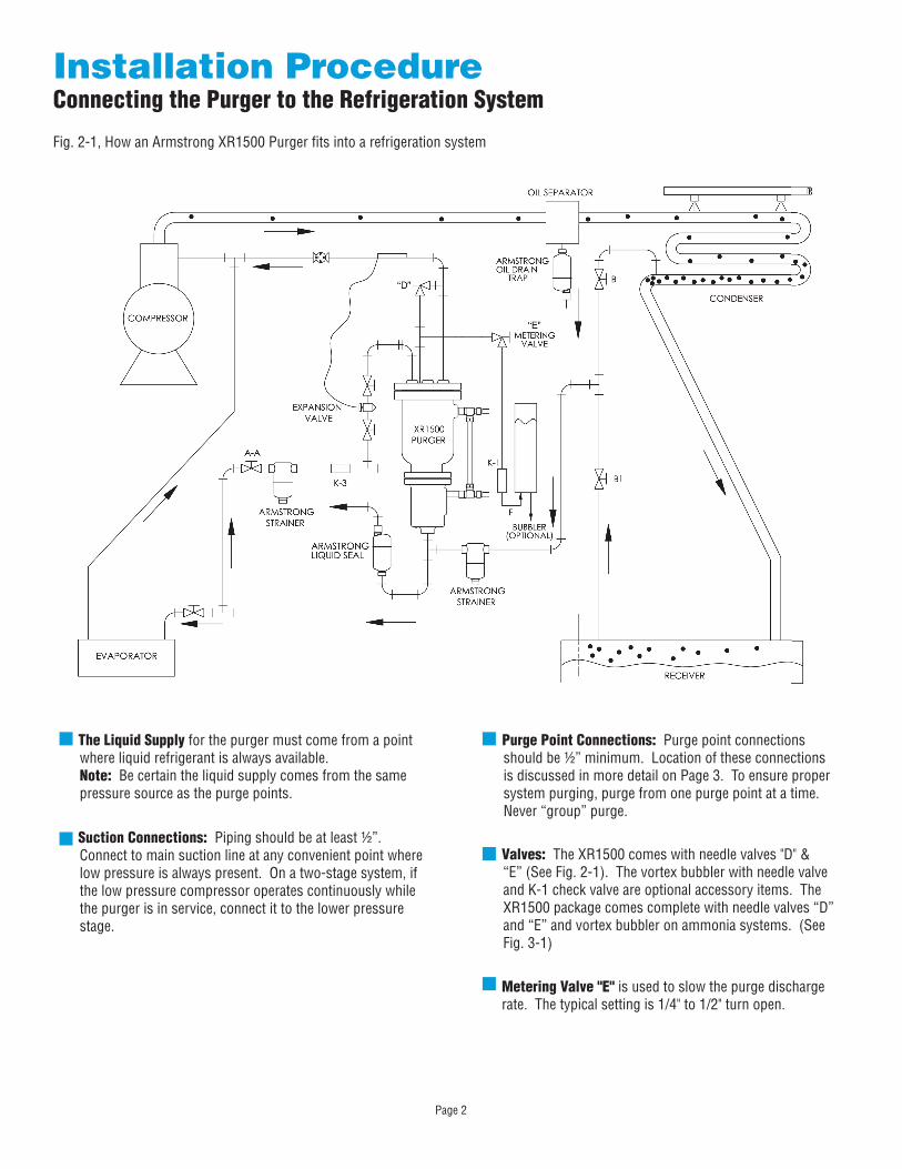
The Liquid Supply for the purger must come from a point where liquid refrigerant is always available.Note: Be certain the liquid supply comes from the same pressure source as the purge points.
Suction Connections: Piping should be at least ½”. Connect to main suction line at any convenient point where low pressure is always present. On a two-stage system, if the low pressure compressor operates continuously while the purger is in service, connect it to the lower pressure stage.
Fig. 2-1, How an Armstrong XR1500 Purger fits into a refrigeration system
Purge Point Connections: Purge point connections should be ½” minimum. Location of these connections is discussed in more detail on Page 3. To ensure proper system purging, purge from one purge point at a time. Never “group” purge.
Valves: The XR1500 comes with needle valves "D" & “E” (See Fig. 2-1). The vortex bubbler with needle valve and K-1 check valve are optional accessory items. The XR1500 package comes complete with needle valves “D” and “E” and vortex bubbler on ammonia systems. (See Fig. 3-1)
Metering Valve "E" is used to slow the purge discharge rate. The typical setting is 1/4" to 1/2" turn open.
Page 3
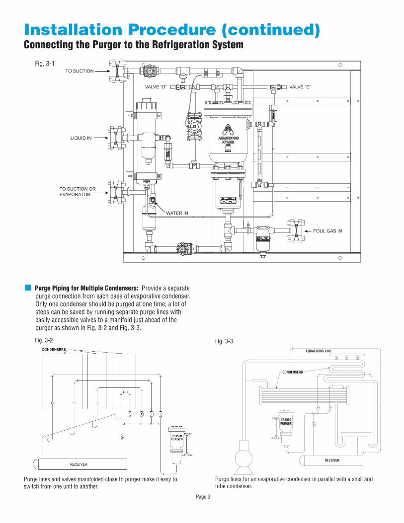
TO SUCTION
VALVE “E”VALVE “D”
LIQUID IN
TO SUCTION OREVAPORATOR
FOUL GAS IN
WATER IN
Installation Procedure (continued)Connecting the Purger to the Refrigeration System
Purge Piping for Multiple Condensers: Provide a separate purge connection from each pass of evaporative condenser. Only one condenser should be purged at one time; a lot of steps can be saved by running separate purge lines with easily accessible valves to a manifold just ahead of the purger as shown in Fig. 3-2 and Fig. 3-3.
Fig. 3-2
Purge lines and valves manifolded close to purger make it easy to switch from one unit to another.
Purge lines for an evaporative condenser in parallel with a shell and tube condenser.
XR1500PURGER
RECEIVER
CONDENSERS
EQUALIZING LINE
Fig. 3-3
Fig. 3-1
Page 4
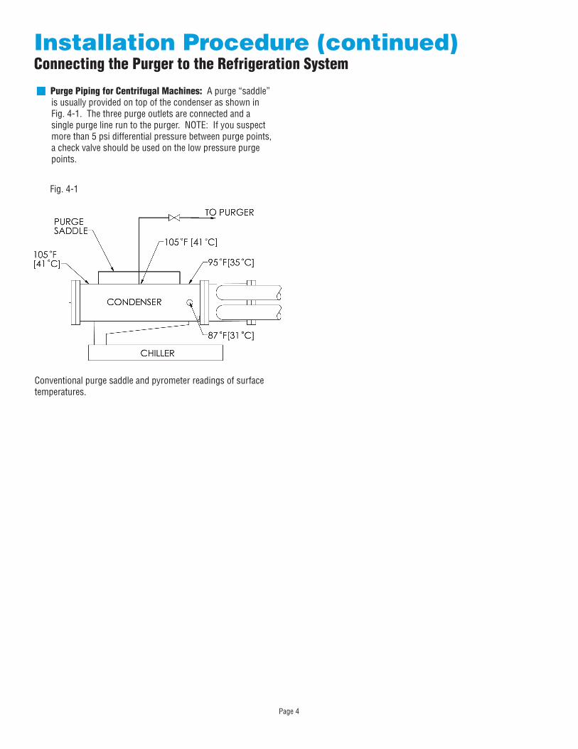
Purge Piping for Centrifugal Machines: A purge “saddle” is usually provided on top of the condenser as shown in Fig. 4-1. The three purge outlets are connected and a single purge line run to the purger. NOTE: If you suspect more than 5 psi differential pressure between purge points, a check valve should be used on the low pressure purge points.
Fig. 4-1
Conventional purge saddle and pyrometer readings of surface temperatures.
Installation Procedure (continued)Connecting the Purger to the Refrigeration System
Page 5
Installation Procedure (continued)Piping TipsPurge Connections for Condensers
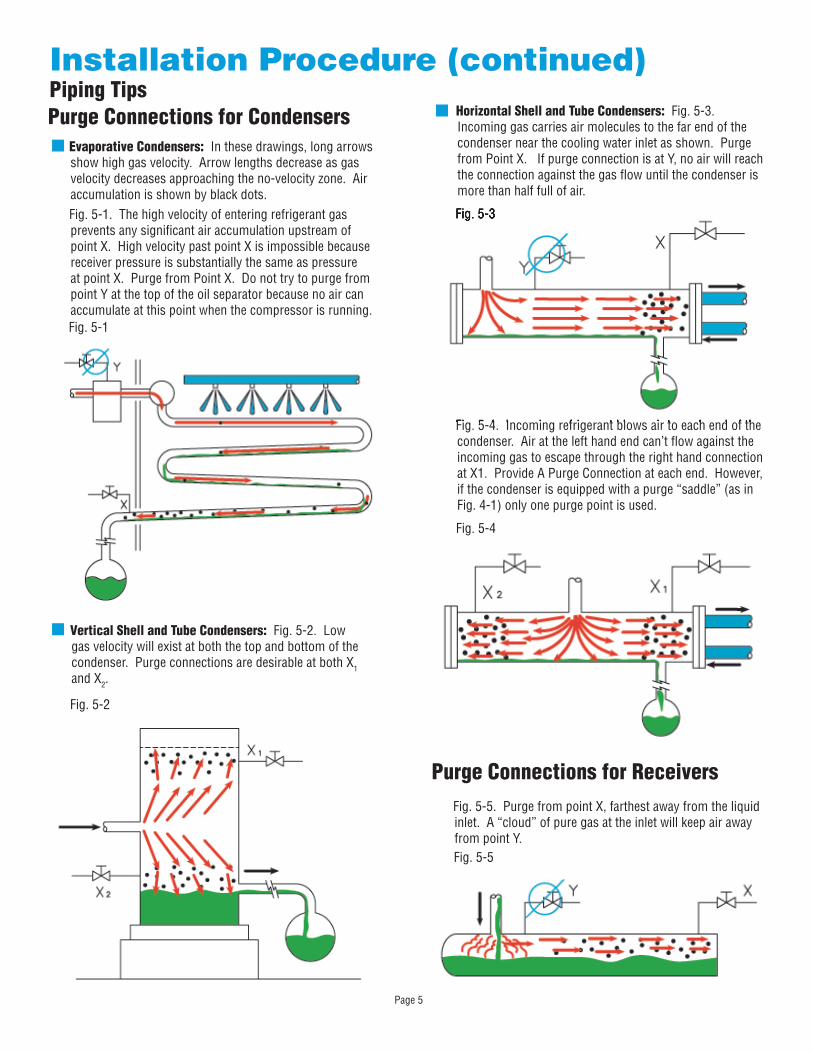
Evaporative Condensers: In these drawings, long arrows show high gas velocity. Arrow lengths decrease as gas velocity decreases approaching the no-velocity zone. Air accumulation is shown by black dots.Fig. 5-1. The high velocity of entering refrigerant gas prevents any significant air accumulation upstream of point X. High velocity past point X is impossible because receiver pressure is substantially the same as pressure at point X. Purge from Point X. Do not try to purge from point Y at the top of the oil separator because no air can accumulate at this point when the compressor is running.
Vertical Shell and Tube Condensers: Fig. 5-2. Low gas velocity will exist at both the top and bottom of the condenser. Purge connections are desirable at both X1 and X2.
Horizontal Shell and Tube Condensers: Fig. 5-3. Incoming gas carries air molecules to the far end of the condenser near the cooling water inlet as shown. Purge from Point X. If purge connection is at Y, no air will reach the connection against the gas flow until the condenser is more than half full of air.
Fig. 5-5. Purge from point X, farthest away from the liquid inlet. A “cloud” of pure gas at the inlet will keep air away from point Y.
Purge Connections for Receivers
Fig. 5-5
Fig. 5-4. Incoming refrigerant blows air to each end of the condenser. Air at the left hand end can’t flow against the incoming gas to escape through the right hand connection at X1. Provide A Purge Connection at each end. However, if the condenser is equipped with a purge “saddle” (as in Fig. 4-1) only one purge point is used.
Fig. 5-1
Fig. 5-2
Fig. 5-3
Fig. 5-4
Fig. 5-4. Incoming refrigerant blows air to each end of the
Fig. 5-3
Page 6
Installation Procedure (continued)Installation Notes
Adherence to the following notes and recommendations are very important in achieving a fully satisfactory, trouble free installation. Please read them carefully.
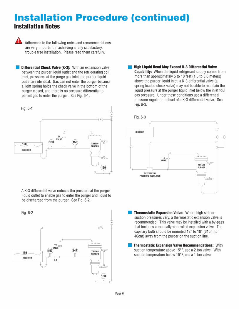
Differential Check Valve (K-3): With an expansion valve between the purger liquid outlet and the refrigerating coil inlet, pressures at the purge gas inlet and purger liquid outlet are identical. Gas can not enter the purger because a light spring holds the check valve in the bottom of the purger closed, and there is no pressure differential to permit gas to enter the purger. See Fig. 6-1.
Fig. 6-1
Fig. 6-2
High Liquid Head May Exceed K-3 Differential Valve Capability: When the liquid refrigerant supply comes from more than approximately 5 to 10 feet (1.5 to 3.0 meters) above the purger liquid inlet, a K-3 differential valve (a spring loaded check valve) may not be able to maintain the liquid pressure at the purger liquid inlet below the inlet foul gas pressure. Under these conditions use a differential pressure regulator instead of a K-3 differential valve. See Fig. 6-3.
Fig. 6-3
Thermostatic Expansion Valve: Where high side or suction pressures vary, a thermostatic expansion valve is recommended. This valve may be installed with a by-pass that includes a manually-controlled expansion valve. The capillary bulb should be mounted 12” to 18” (31cm to 46cm) away from the purger on the suction line.
A K-3 differential valve reduces the pressure at the purger liquid outlet to enable gas to enter the purger and liquid to be discharged from the purger. See Fig. 6-2.
RECEIVER
TXVALVE
XR1500PURGER
150150 150
150
150150
150
147
K-3RECEIVER
XR1500PURGER
TXVALVE
RECEIVER
DIFFERENTIALPRESSURE REGULATOR
TXVALVE
XR1500PURGER
Thermostatic Expansion Valve Recommendations: With suction temperature above 15°F, use a 2 ton valve. With suction temperature below 15°F, use a 1 ton valve.
Page 7
Installation Procedure (continued)Installation Notes
Warning: Use pipe thread compound sparingly An excess may prevent the expansion valve from operating.
Avoid Pockets in the foul gas line from the condenser to the purger. They will form a liquid seal which will prevent flow of gas from entering the purger. If pockets cannot be avoided, use a liquid seal trap to remove liquid. See Bulletin 760.
Excessive Oil will interfere with purger operation. Remove oil before you install your purger. Prevent further oil accumulation by installing a separator in the discharge line from the compressor. This separator should be drained by an Armstrong Oil Trap that discharges to the compressor crank case through a suitable oil filter or to an oil barrel.
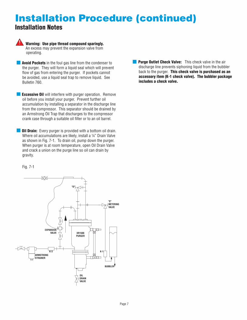
Oil Drain: Every purger is provided with a bottom oil drain. Where oil accumulations are likely, install a ¼” Drain Valve as shown in Fig. 7-1. To drain oil, pump down the purger. When purger is at room temperature, open Oil Drain Valve and crack a union on the purge line so oil can drain by gravity.
Purge Outlet Check Valve: This check valve in the air discharge line prevents siphoning liquid from the bubbler back to the purger. This check valve is purchased as an accessory item (K-1 check valve) The bubbler package includes a check valve
Fig. 7-1
XR1500 PURGER
K-1
BUBBLER
"E" METERING VALVE
K-3
OIL DRAIN VALVE
ARMSTRONG STRAINER
EXPANSION VALVE
"D"
Page 8
Start Up ProcedureArmstrong XR1500 Mechanical Purger
Prime and Chill: The purger can be primed and chilled in one operation by opening liquid supply valve and suction line valves. Crack open needle valve “D” (See Fig. 2-1). When liquid rises in the gauge glass to approximately 1 inch (2.5cm) from the top, close valve “D”. The capillary bulb will control the Tx valve and chill the purger body.
Turn on Foul Gas: Open one “foul gas” valve at a time. Never purge from more than one point at a time for best purge results.
Operation: The Armstrong Mechanical Purger was designed to purge from one purge point at a time through manual purge valves. This is a "hands on" purging operation. The liquid supply and foul gas pressures to the purger should be the same pressure. After the purger has been primed with liquid refrigerant and the purger body has chilled, open the first purge point valve slowly. Allow the purger to purge from the first purge point for approximately 30 minutes then close this valve. Slowly open the next purge point valve and repeat the above sequence through all the purge points.Note: Never open more than one purge point valve during the purge operation. This can cause back flow between purge points and result in poor air removal.
Liquid Seal Trap: Condensation of purge gas in long or exposed lines will occur if the gas temperature exceeds the temperature of the air surrounding the purge gas piping. This condensation presents no problem if the amount is less than the make-up liquid required to offset purger heat gain. When the amount condensed exceeds make-up requirements, a seal of liquid refrigerant will form ahead of the purger.When such a seal forms, gas cannot get to the purger. Now the Tx valve has to supply only enough liquid to keep the purger chilled and none for condensing gas so the seal gets deeper and deeper. To cure this problem the XR1500 Series Package Purger is equipped with an Armstrong 1011-6 liquid seal trap (for ammonia service). The trap discharges to the low pressure or suction side of the system. This trap is a beneficial addition to any existing system being retrofitted to automatic control. (See Fig. 2-1)
Page 9
Limited Warranty and Remedy
Armstrong International, Inc. (“Armstrong”) warrants to the original user of those products supplied by it and used in the service and in the manner for which they are intended, that such products shall be free from defects in material and workmanship for a period of one (1) year from the date of installation, but not longer than 15 months from the date of shipment from the factory, [unless a Special Warranty Period applies, as listed below]. This warranty does not extend to any product that has been subject to misuse, neglect or alteration after shipment from the Armstrong factory. Except as may be expressly provided in a written agreement between Armstrong and the user, which is signed by both parties, Armstrong DOES NOT MAKE ANY OTHER REPRESENTATIONS OR WARRANTIES, EXPRESS OR IMPLIED, INCLUDING, BUT NOT LIMITED TO, ANY IMPLIED WARRANTY OF MERCHANTABILITY OR ANY IMPLIED WARRANTY OF FITNESS FOR A PARTICULAR PURPOSE.
The sole and exclusive remedy with respect to the above limited warranty or with respect to any other claim relating to the products or to defects or any condition or use of the products supplied by Armstrong, however caused, and whether such claim is based upon warranty, contract, negligence, strict liability, or any other basis or theory, is limited to Armstrong’s repair or replacement of the part or product, excluding any labor or any other cost to remove or install said part or product, or at Armstrong’s option, to repayment of the purchase price. As a condition of enforcing any rights or remedies relating to Armstrong products, notice of any warranty or other claim relating to the products must be given in writing to Armstrong: (i) within 30 days of last day of the applicable warranty period, or (ii) within 30 days of the date of the manifestation of the condition or occurrence giving rise to the claim, whichever is earlier. IN NO EVENT SHALL ARMSTRONG BE LIABLE FOR SPECIAL, DIRECT, INDIRECT, INCIDENTAL OR CONSEQUENTIAL DAMAGES, INCLUDING, BUT NOT LIMITED TO, LOSS OF USE OR PROFITS OR INTERRUPTION OF BUSINESS. The Limited Warranty and Remedy terms herein apply notwithstanding any contrary terms in any purchase order or form submitted or issued by any user, purchaser, or third party and all such contrary terms shall be deemed rejected by Armstrong.

Armstrong Steam and Condensate Group816 Maple Street, Three Rivers, MI 49093 – USA Phone: (269) 273-1415 Fax: (269) 278-6555 armstronginternational.com
IB-75Printed in U.S.A. - 01/12
© 2012 Armstrong International, Inc.