artisan technology group is your source for quality … · · 2013-03-02artisan technology group...
TRANSCRIPT

Artisan Technology Group is your source for quality new and certified-used/pre-owned equipment
• FAST SHIPPING AND DELIVERY
• TENS OF THOUSANDS OF IN-STOCK ITEMS
• EQUIPMENT DEMOS
• HUNDREDS OF MANUFACTURERS SUPPORTED
• LEASING/MONTHLY RENTALS
• ITAR CERTIFIED SECURE ASSET SOLUTIONS
SERVICE CENTER REPAIRSExperienced engineers and technicians on staff at our full-service, in-house repair center
WE BUY USED EQUIPMENTSell your excess, underutilized, and idle used equipment We also offer credit for buy-backs and trade-inswww.artisantg.com/WeBuyEquipment
REMOTE INSPECTIONRemotely inspect equipment before purchasing with our interactive website at www.instraview.com
LOOKING FOR MORE INFORMATION? Visit us on the web at www.artisantg.com for more information on price quotations, drivers, technical specifications, manuals, and documentation
Contact us: (888) 88-SOURCE | [email protected] | www.artisantg.com
SMViewInstra

BSA-SeriesBrushless Servo Amplifier
Rockwell Automation/Electro-Craft6950 Washington Avenue SouthEden Prairie, MN 55344
Instruction Manual
T H E R I G H T C O M P A N Y . T H E R I G H T S O L U T I O N .
Artisan Technology Group - Quality Instrumentation ... Guaranteed | (888) 88-SOURCE | www.artisantg.com

P/N 0013-1014-002 Rev G
Important User InformationBecause of the variety of uses for the products described in this publication, those responsible for the application and use of this control equipment must satisfy themselves that all necessary steps have been taken to assure that each application and use meets all performance and safety requirements, including any applicable laws, regulations, codes and standards.
The illustrations, charts, sample programs and layout examples shown in this guide are intended solely for purposes of example. Since there are many variables and requirements associated with any particular installation, Electro-Craft does not assume responsibility or lia-bility (to include intellectual property liability) for actual use based upon the examples shown in this publication.
Reproduction of the contents of this copyrighted publication, in whole or in part, without written permission of Reliance Motion Control, Inc., is prohibited.
Throughout this manual we use notes to make you aware of safety considerations. For example:
Attention statements help you to:
◆ identify a hazard
◆ avoid the hazard
◆ recognize the consequences
© 2000 Rockwell International Corporation. All rights reserved. Printed in the United States of America.
Microsoft, MS-DOS and Windows are trademarks of Microsoft Corporation. UL and cUL are registered trademarks of Underwriters Laboratories.
!
Intro
This symbol identifies information about practices or circum-stances that can lead to personal injury or death, property damage or economic loss.
TIPThis symbol identifies information that is critical for successful application and understanding of the product.
Artisan Technology Group - Quality Instrumentation ... Guaranteed | (888) 88-SOURCE | www.artisantg.com

Installation Manual for BSA-Series
Table of Contents
IntroTable of Contents
Table of Contents Intro-1
List of Figures Intro-3
List of Tables Intro-5
CHAPTER 1 Introduction Introduction to the BSA-Series . . . . . . . . . . . . . . . . . . . . . . . . . . . . . . . . . . . 1-1
How to Use This Manual . . . . . . . . . . . . . . . . . . . . . . . . . . . . . . . . . . . . . 1-2
CHAPTER 2 InstallationMounting The Drive Modules . . . . . . . . . . . . . . . . . . . . . . . . . . . . . . . . . . . 2-1
Power Wiring . . . . . . . . . . . . . . . . . . . . . . . . . . . . . . . . . . . . . . . . . . . . . 2-1
Motor Mounting and Wiring . . . . . . . . . . . . . . . . . . . . . . . . . . . . . . . . . . . . 2-1
External Shunt Mounting and Wiring (Optional) . . . . . . . . . . . . . . . . . . . . . . . . 2-2
CHAPTER 3 Interface CircuitryDrive Module Interface Connectors . . . . . . . . . . . . . . . . . . . . . . . . . . . . . . . . 3-1
Drive Module Interface Signal Specifications . . . . . . . . . . . . . . . . . . . . . . . . . . . 3-1
CHAPTER 4 Start-Up and AdjustmentsInitial Start-Up Procedure . . . . . . . . . . . . . . . . . . . . . . . . . . . . . . . . . . . . . . 4-1
Adjustments . . . . . . . . . . . . . . . . . . . . . . . . . . . . . . . . . . . . . . . . . . . . . 4-2
CHAPTER 5 Troubleshooting & MaintenanceIntroduction. . . . . . . . . . . . . . . . . . . . . . . . . . . . . . . . . . . . . . . . . . . . . . 5-1
BSA-Series LEDs . . . . . . . . . . . . . . . . . . . . . . . . . . . . . . . . . . . . . . . . . 5-1
CHAPTER 6 Optional AccessoriesPRO-Series Controller Kit Installation Instructions . . . . . . . . . . . . . . . . . . . . . . . 6-1
BSA-Series Control Station . . . . . . . . . . . . . . . . . . . . . . . . . . . . . . . . . . . . . 6-1
CHAPTER 7 SpecificationsBSA-15, BSA-30, BSA-30X Specifications . . . . . . . . . . . . . . . . . . . . . . . . . . . . . 7-1
Motor/BSA-Series System Specifications . . . . . . . . . . . . . . . . . . . . . . . . . . . . . 7-2
CHAPTER 8 Replacement PartsDrive Modules . . . . . . . . . . . . . . . . . . . . . . . . . . . . . . . . . . . . . . . . . . . . 8-1
Accessories . . . . . . . . . . . . . . . . . . . . . . . . . . . . . . . . . . . . . . . . . . . . . . 8-1
Motors . . . . . . . . . . . . . . . . . . . . . . . . . . . . . . . . . . . . . . . . . . . . . . . . . 8-2
PRO-Series Kits. . . . . . . . . . . . . . . . . . . . . . . . . . . . . . . . . . . . . . . . . . . . 8-2
Cables . . . . . . . . . . . . . . . . . . . . . . . . . . . . . . . . . . . . . . . . . . . . . . . 8-2
Motor Connectors . . . . . . . . . . . . . . . . . . . . . . . . . . . . . . . . . . . . . . . . 8-3
Motor Shaft Seal Kits . . . . . . . . . . . . . . . . . . . . . . . . . . . . . . . . . . . . . . 8-3
CHAPTER 9 Reference DrawingsList of Drawings . . . . . . . . . . . . . . . . . . . . . . . . . . . . . . . . . . . . . . . . . . . 9-1
. . . . . . . . . . . . . . . . . . . . . . . . . . . . . . . . . . . . . . . . . . . . . . 9-2
Artisan Technology Group - Quality Instrumentation ... Guaranteed | (888) 88-SOURCE | www.artisantg.com

Intro-2 Table of Contents
P/N 0013-1014-002 Rev G
Documentation Improvement Help-1
Our Warranty Help-3
Index of Topics Help-5
Product Support Help-7
Artisan Technology Group - Quality Instrumentation ... Guaranteed | (888) 88-SOURCE | www.artisantg.com

Installation Manual for BSA-Series
List of Figures
IntroList of Figures
CHAPTER 1 Introduction F-Series & H-Series Brushless Motors, and BSA-30, or BSA-15 Drive & LD-Series Motor 1-1
CHAPTER 2 InstallationS&F-Series Motor and Encoder Connections . . . . . . . . . . . . . . . . . . . . . . . . 2-3
LD-Series Motor and Encoder Connections . . . . . . . . . . . . . . . . . . . . . . . . . 2-4
CHAPTER 3 Interface CircuitryBSA-Series Logic Connectors and Signal Names . . . . . . . . . . . . . . . . . . . . . . 3-1
CHAPTER 4 Start-Up and AdjustmentsPotentiometer, Fuse, Test Point, and Jumper Locations . . . . . . . . . . . . . . . . . . 4-3
BSA-15/Motor Matrix . . . . . . . . . . . . . . . . . . . . . . . . . . . . . . . . . . . . . 4-4
BSA-30/Motor Matrix . . . . . . . . . . . . . . . . . . . . . . . . . . . . . . . . . . . . . 4-5
BSA-30X/Motor Matrix . . . . . . . . . . . . . . . . . . . . . . . . . . . . . . . . . . . . 4-6
BSA-Series Set-Up . . . . . . . . . . . . . . . . . . . . . . . . . . . . . . . . . . . . . . . 4-7
CHAPTER 5 Troubleshooting & Maintenance
CHAPTER 6 Optional AccessoriesBSA-Series Control Station. . . . . . . . . . . . . . . . . . . . . . . . . . . . . . . . . . . 6-1
CHAPTER 7 Specifications
CHAPTER 8 Replacement Parts
CHAPTER 9 Reference DrawingsBSA-Series Outline/Mounting . . . . . . . . . . . . . . . . . . . . . . . . . . . . . . . . 9-2
BSA-Series Power Wiring . . . . . . . . . . . . . . . . . . . . . . . . . . . . . . . . . . . 9-3
BSA-Series, Interface Logic . . . . . . . . . . . . . . . . . . . . . . . . . . . . . . . . . . 9-4
Cables, BSA-Series . . . . . . . . . . . . . . . . . . . . . . . . . . . . . . . . . . . . . . . 9-5
Cables, LD-Series, Power . . . . . . . . . . . . . . . . . . . . . . . . . . . . . . . . . . . 9-6
Cables, LD-Series, Encoder . . . . . . . . . . . . . . . . . . . . . . . . . . . . . . . . . . 9-7
BSA-Series External Shunt . . . . . . . . . . . . . . . . . . . . . . . . . . . . . . . . . . 9-8
Outline and Mounting, S-Series Motors . . . . . . . . . . . . . . . . . . . . . . . . . . . 9-9
Outline and Mounting, F-Series Motors . . . . . . . . . . . . . . . . . . . . . . . . . . . 9-10
Outline and Mounting, LD-Series Motors . . . . . . . . . . . . . . . . . . . . . . . . . . 9-11
Installation, PRO-Series Kit . . . . . . . . . . . . . . . . . . . . . . . . . . . . . . . . . . 9-12
Outline, Transformer . . . . . . . . . . . . . . . . . . . . . . . . . . . . . . . . . . . . . . 9-13
Artisan Technology Group - Quality Instrumentation ... Guaranteed | (888) 88-SOURCE | www.artisantg.com

Intro-4 List of Figures
P/N 0013-1014-002 Rev G
Artisan Technology Group - Quality Instrumentation ... Guaranteed | (888) 88-SOURCE | www.artisantg.com

Installation Manual for BSA-Series
List of Tables
IntroList of Tables
CHAPTER 1 Introduction
CHAPTER 2 Installation
CHAPTER 3 Interface CircuitryP1 Connections . . . . . . . . . . . . . . . . . . . . . . . . . . . . . . . . . . . . . . . . . . . . . . . 3-1
P2 Connections . . . . . . . . . . . . . . . . . . . . . . . . . . . . . . . . . . . . . . . . . . . . . . . 3-2
P3 Connections . . . . . . . . . . . . . . . . . . . . . . . . . . . . . . . . . . . . . . . . . . . . . . . 3-2
CHAPTER 4 Start-Up and Adjustments
CHAPTER 5 Troubleshooting & MaintenanceLED Diagnostics . . . . . . . . . . . . . . . . . . . . . . . . . . . . . . . . . . . . . . . . . . . . . . 5-1
CHAPTER 6 Optional Accessories
CHAPTER 7 Specifications
CHAPTER 8 Replacement Parts
CHAPTER 9 Reference DrawingsReference Drawing Descriptions . . . . . . . . . . . . . . . . . . . . . . . . . . . . . . . . . . . . 9-1
Artisan Technology Group - Quality Instrumentation ... Guaranteed | (888) 88-SOURCE | www.artisantg.com

Intro-6 List of Tables
P/N 0013-1014-002 Rev G
Artisan Technology Group - Quality Instrumentation ... Guaranteed | (888) 88-SOURCE | www.artisantg.com

Installation Manual for BSA-Series
CHAPTER 1: Introduction
Introduction to the BSA-SeriesThe BSA-Series is a high performance square-wave current brushless servo drive employing a modular package suited to single or multi-axis applications. Using conventional analog velocity control (with an encoder based analog tachometer), potentiometer adjustments, and non-iso-lated 120 VAC input, the BSA-Series is a lower power, lower cost alternative to the Electro-Craft BRU-200 digital brushless servo drive. The BSA-Series powers the standard Electro-Craft S-Series, F-Series, and LD-Series permanent magnet synchronous motors along with other brushless motors that have conventional commutation and encoder feedback. A picture of stan-dard BSA-Series components is shown in Figure 1.1.
For single axis positioning applications, the Electro-Craft PRO-Series controller card kits mount inside the BSA-Series drive modules. This eliminates the need for a separate controller package.
FIGURE 1.1 F-Series & H-Series Brushless Motors, and BSA-30, or BSA-15 Drive & LD-Series Motor
Artisan Technology Group - Quality Instrumentation ... Guaranteed | (888) 88-SOURCE | www.artisantg.com

1-2 Introduction
P/N 0013-1014-002 Rev G
How to Use This ManualThis manual describes the Electro-Craft BSA-Series brushless servo drives along with standard Electro-Craft motors recommended for use with the BSA-Series. The manual is intended for use by qualified engineers or technicians directly involved in the installation, operation, and field level maintenance of the drives and motors.
Artisan Technology Group - Quality Instrumentation ... Guaranteed | (888) 88-SOURCE | www.artisantg.com

Installation Manual for BSA-Series
CHAPTER 2: Installation
Mounting The Drive ModulesThe BSA-Series drive modules are designed for simple installation on a flat surface such as the back wall or plate of an enclosure. The environment in the enclosure must be clean and free of oil mist, coolant mist, conductive particles, and corrosive chemicals. For industrial applications, a NEMA 12 or equivalent enclosure is recommended. The enclosure must be properly sized (and ventilated or cooled if required) to insure that the BSA-Series maximum ambient temper-ature is not exceeded. The BSA-Series drives must be mounted vertically to take advantage of natural convection cooling.
Drawing 9106-0029 shows the BSA-Series drive module dimensions including space require-ments around the module for cable clearance and air flow. In some installations that limit air flow it may be necessary to provide a fan to increase air flow over the drive module. Note that the mounting hole pattern for the BSA-Series drives is the same as for the Electro-Craft BRU-200 brushless servo drives.
Power Wiring
Drawing 9106-0031 shows the required power wiring for a typical installation. The phasing of the three phase drive module outputs R, S, and T must conform to the motor R, S, and T leads for proper operation. Earth ground must be connected as shown to insure a safe and proper installation. Wiring of the transformer, line fuses, and wire gauge sizes is also covered in this drawing.
Motor Mounting and WiringMotor mounting dimensions for LD-Series, S-Series, and F-Series are located in the Reference Drawings starting on page 9-1.
Some motor mounting considerations are as follows:
1. Do not run motor unmounted. Attach all motor cables after motor is mounted.
2. Mount motor with connectors pointing downward and use cable drip-loops to keep liq-uids flowing away from connectors.
!WARNING: Danger of electrical shock or burn. Only qualified indi-viduals should work on this equipment. Dangerous voltages may exist after power is removed. Disconnect all power before working on equipment.
!CAUTION: Do not connect the BSA-Series drives to a 230 VAC RMS 50/60 Hz Single Phase AC input. Maximum nominal input AC voltage is 120 VAC RMS 50/60 Hz Single Phase.
Artisan Technology Group - Quality Instrumentation ... Guaranteed | (888) 88-SOURCE | www.artisantg.com

2-2 Installation
P/N 0013-1014-002 Rev G
3. Consider motor case temperature if necessary to safeguard operator and maintenance staff. Maximum case temperature is about 212°F (100°C) for a motor used at continuous rating at 104°F (40°C) ambient.
Motor and encoder connections are shown on pages 2-3 and 2-4.
External Shunt Mounting and Wiring (Optional)
The external shunt mounts to a flat surface just like the BSA-Series drive module. The same mounting restrictions apply to the external shunt as to the BSA-Series. Drawing 9106-0027 shows the external shunt resistor dimensions and connection diagram.
!CAUTION: Do not substitute the BRU-200 External Shunt resistor that is the same physical size, but a different resistance value.
Artisan Technology Group - Quality Instrumentation ... Guaranteed | (888) 88-SOURCE | www.artisantg.com

Installation 2-3
Installation Manual for BSA-Series
FIGURE 2.1 S&F-Series Motor and Encoder Connections
Artisan Technology Group - Quality Instrumentation ... Guaranteed | (888) 88-SOURCE | www.artisantg.com

2-4 Installation
P/N 0013-1014-002 Rev G
FIGURE 2.2 LD-Series Motor and Encoder Connections
Artisan Technology Group - Quality Instrumentation ... Guaranteed | (888) 88-SOURCE | www.artisantg.com
Installation Manual for BSA-Series
CHAPTER 3: Interface Circuitry
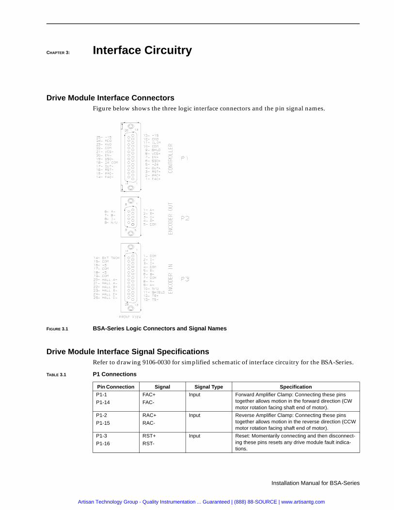
Drive Module Interface ConnectorsFigure below shows the three logic interface connectors and the pin signal names.
Drive Module Interface Signal SpecificationsRefer to drawing 9106-0030 for simplified schematic of interface circuitry for the BSA-Series.
FIGURE 3.1 BSA-Series Logic Connectors and Signal Names
TABLE 3.1 P1 Connections
Pin Connection Signal Signal Type Specification
P1-1
P1-14
FAC+
FAC-
Input Forward Amplifier Clamp: Connecting these pins together allows motion in the forward direction (CW motor rotation facing shaft end of motor).
P1-2
P1-15
RAC+
RAC-
Input Reverse Amplifier Clamp: Connecting these pins together allows motion in the reverse direction (CCW motor rotation facing shaft end of motor).
P1-3
P1-16
RST+
RST-
Input Reset: Momentarily connecting and then disconnect-ing these pins resets any drive module fault indica-tions.
Artisan Technology Group - Quality Instrumentation ... Guaranteed | (888) 88-SOURCE | www.artisantg.com

3-2 Interface Circuitry
P/N 0013-1014-002 Rev G
P1-4
P1-17
OUT+
OUT-
Output Normally, “open” relay contacts that close when the drive is enabled. The relay opens when the drive is inhibited. Maximum, 0.3 Amp contact rating at 24 VDC.
P1-5
P1-18
+24 VDC
-24 VDC
Output Available 24 VDC supply for external use. Maximum, 1.0 Amp output.
Common return for +24 VDC supply. Common internal to BSA and not connected to chassis. Connection to chassis common if desired.
P1-6
P1-19
SSO+
SSO-
Output Normally, “open” relay that closes when drive is ready. The relay opens if there is a drive fault. Maximum 0.3 Amp contact rating at 24 VDC.
P1-7
P1-20
Enable+
Enable-
Input Connecting these two pins together enables the drive; disconnecting them inhibits the drive.
P1-8
P1-21
VCS+
VCS-
Input Velocity command signal: ± 10 VDC input command signal range with 22 K ohms impedance. Absolute max input signal range is ± 12 VDC. Positive volts from VCS+ to VCS- results in CW motor rotation fac-ing shaft end of motor.
P1-9 Shield Shield Connected to chassis common internal to drive.
P1-10
P1-22
Common Common Common returns for logic supplies. Connected to chassis common internal to drive.
P1-24 MCO Output Motor current output: ± 10 VDC equal to zero to peak current of drive module. Does not include effect of cur-rent foldback.
P1-12 CMD Monitor Output VCS monitor: signal representing the command input signal after the VCS scaling potentiometer.
P1-23 MVO Output Motor velocity output: Signal from encoder tachometer representing motor speed.
P1-11 External Current Limit
Input If the I Limit pot is set fully CW and a 100k ohm resis-tor connected from this pin to common, the available current will be reduced by about 50%. A 32.2k ohm resistor will reduce the available current by about 25%. The exact amount of reduction is a function of the internal current limit for the motor being used.
P1-13
P1-25
+15 VDC
-15 VDC
Output NOT FOR EXTERNAL USE
TABLE 3.2 P2 Connections
Pin Connection Signal Signal Type Specification
P2 Encoder Out Output A+, A-, B+, I+, and I- encoder signals from the motor are unbuffered for use by the position controller. Sig-nal A+ leads and signal B+ for CW motor rotation (fac-ing shaft end of motor). (+5 VDC and common for the motor encoder can be supplied externally as an option with some jumper configurations).
TABLE 3.3 P3 Connections
Pin Connection Signal Signal Type Specification
P3 Encoder In Input Power supply and signal connections for motor encoder and thermostat.
TABLE 3.1 P1 Connections (continued)
Pin Connection Signal Signal Type Specification
Artisan Technology Group - Quality Instrumentation ... Guaranteed | (888) 88-SOURCE | www.artisantg.com

Installation Manual for BSA-Series
CHAPTER 4: Start-Up and Adjustments
Initial Start-Up Procedure
1. Measure voltage between BSA-Series terminals marked L1 & L2 to insure incoming power is off. Observe that LOGIC P/S LED is off.
2. Disconnect the wires connected to terminals marked L1 & L2. Arrange these wires to safe position for testing of incoming voltage.
3. Turn incoming power on and measure line voltage to insure that it is in the proper volt-age range (see specifications on page 7-1).
4. If incoming voltage is the correct voltage then turn power off and reconnect the wires to terminals L1 & L2.
5. With incoming power still off, disconnect motor leads from BSA-Series terminals R, S, and T. Verify with an ohmmeter that the resistance between BSA-Series terminals R to GND, S to GND, and T to GND is 100K ohms minimum.
6. Verify that the BSA-Series has the correct potentiometer and jumper settings. The cover of the BSA-Series drive must be removeddrawing (refer to drawing 9106-0011). Draw-ing on page 4-3 shows potentiometer, fuse, test point locations, and jumper locations. Recommended set-up for the BSA-15, BSA-30, and the BSA-30X and the standard Elec-tro-Craft motors is shown pages 4-4, 4-5, and 4-6 respectively. Connect all interface cables to the BSA-Series.
7. Apply incoming power with the drive inhibited and observe the LEDs. The LOGIC P/S LED should be on while the other LEDs should be off.
8. Connect a DC voltmeter between the MVO test point and common. Observe that the voltage goes negative when the motor is rotated CW and positive when the motor is turned CCW as viewed from the motor drive end.
9. Remove incoming power and observe that all BSA-Series LEDs turn off within one sec-ond.
10. Disconnect the motor(s) from the mechanical load(s) when initially checking out the system. If this is not possible, then take adequate precautions in the event of a fault.
11. Connect the motor R, S, and T to the BSA-Series. Be sure to connect R, S, and T of motor to R, S, and T of the drive. Also, connect a ground wire from the motor case to BSA-Series terminal GND. With the drive inhibited, reapply incoming power and observe proper power up diagnostics as indicated by module LEDs.
12. Set a low current limit (25% is a typical value while fully CCW is zero) using the I Limit potentiometer. Apply a small positive voltage (about 0.5 VDC) to the VCS inputs of the drive. Enable the drive and observe CW rotation of the motor shaft as viewed facing
!WARNING: Danger of electrical shock or burn. Only qualified indi-viduals should work on this equipment. Disconnect all power before working on equipment. Dangerous voltages may exist after power is removed.
Artisan Technology Group - Quality Instrumentation ... Guaranteed | (888) 88-SOURCE | www.artisantg.com

4-2 Start-Up and Adjustments
P/N 0013-1014-002 Rev G
the motor drive end. If motor does not turn CW, check that motor power wires and encoder wires are connected to the drive properly (Motor and Encoder Connection drawings on pages 2-3 and 2-4).
13. After system installation is verified, return the current to a value to suit the application. Approximate settings are as follows:
Number Turns CWPercent Peak Current (Approximate)
5 20%
7 33%
10 53%
12 73%
15 100%
The average current limit is always 50% of the peak current limit.
AdjustmentsThe BSA-Series brushless drives use conventional jumpers and potentiometers to configure the drive to specific motor and load combinations. The wide input voltage range of 108-132 VAC rms is accommodated automatically and the dissipative shunt regulator automatically tracks the internal DC bus.
The BSA-Series has several jumpers, potentiometers, and test points that are shown in the draw-ing on page 4-4. Factory installed locations for the jumpers are indicated.
Standard drive/motor/load combinations are configured on pages 4-4, 4-5, and 4-6 showing recommended jumper and potentiometer settings. The resistance of the potentiometers is easily measured with the pot test points (refer to Potentiometer, Fuse, Test Point, and Jumper Locations on page 4-4, 4-5, and 4-6).
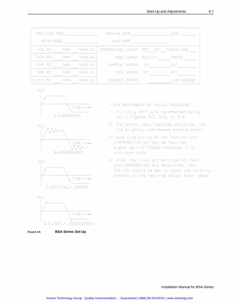
Final adjustment or fine tuning of the potentiometers may be required depending on the appli-cation performance requirements. BSA-Series Set-Up on page 4-7 shows typical tachometer responses (MVO test point) for various adjustments.
Artisan Technology Group - Quality Instrumentation ... Guaranteed | (888) 88-SOURCE | www.artisantg.com

Start-Up and Adjustments 4-3
Installation Manual for BSA-Series
Po
FIGURE 4.1 Potentiometer, Fuse, Test Point, and Jumper Locations
Artisan Technology Group - Quality Instrumentation ... Guaranteed | (888) 88-SOURCE | www.artisantg.com

4-4 Start-Up and Adjustments
P/N 0013-1014-002 Rev G
FIGURE 4.2 BSA-15/Motor Matrix
Artisan Technology Group - Quality Instrumentation ... Guaranteed | (888) 88-SOURCE | www.artisantg.com

Start-Up and Adjustments 4-5
Installation Manual for BSA-Series
FIGURE 4.3 BSA-30/Motor Matrix
Artisan Technology Group - Quality Instrumentation ... Guaranteed | (888) 88-SOURCE | www.artisantg.com

4-6 Start-Up and Adjustments
P/N 0013-1014-002 Rev G
FIGURE 4.4 BSA-30X/Motor Matrix
Artisan Technology Group - Quality Instrumentation ... Guaranteed | (888) 88-SOURCE | www.artisantg.com
Start-Up and Adjustments 4-7
Installation Manual for BSA-Series
FIGURE 4.5 BSA-Series Set-Up
Artisan Technology Group - Quality Instrumentation ... Guaranteed | (888) 88-SOURCE | www.artisantg.com

4-8 Start-Up and Adjustments
P/N 0013-1014-002 Rev G
Artisan Technology Group - Quality Instrumentation ... Guaranteed | (888) 88-SOURCE | www.artisantg.com

Installation Manual for BSA-Series
CHAPTER 5: Troubleshooting & Maintenance
IntroductionThe BSA-Series drive has been designed to provide troubleshooting aids that help isolate any problems to the incoming power, drive, motor and encoder, position controller, cables, and mechanical system. If a BSA-Series drive is found to have a failure, then the drive should be replaced. All jumper and potentiometer settings should be duplicated on the replacement unit to maintain the same performance.
Maintenance for the BSA-Series is unnecessary. The BSA-Series has no fans so the primary consideration is to insure that the BSA-Series is operated in a properly sized and ventilated NEMA-12 (or equivalent) enclosure with proper fusing.
BSA-Series LEDs
TABLE 5.1 LED Diagnostics
LED Label LED Color Description
LOGIC P/S Green Off = No incoming AC or if AC is present, then drive has internal power supply failure.
1, 2, 3 Red Off = No Fault
1 Red On = Motor Over Temperature
2 Red On = Over Current (output short-circuit)
3 Red On = Bus Over Voltage
1, 2 Red On = AC Line Loss
2, 3 Red On = Drive Over Temperature
1, 3 Red On = Logic Supply Fault
Artisan Technology Group - Quality Instrumentation ... Guaranteed | (888) 88-SOURCE | www.artisantg.com

5-2 Troubleshooting & Maintenance
P/N 0013-1014-002 Rev G
Artisan Technology Group - Quality Instrumentation ... Guaranteed | (888) 88-SOURCE | www.artisantg.com
Installation Manual for BSA-Series
CHAPTER 6: Optional Accessories
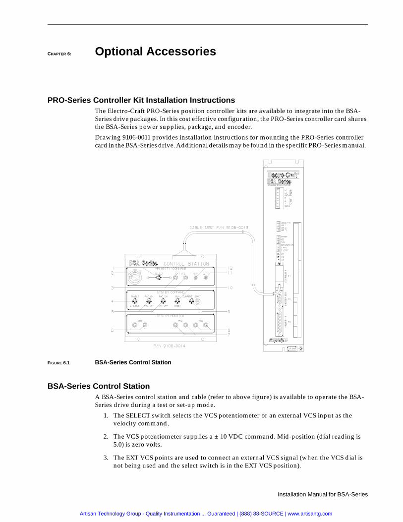
PRO-Series Controller Kit Installation InstructionsThe Electro-Craft PRO-Series position controller kits are available to integrate into the BSA-Series drive packages. In this cost effective configuration, the PRO-Series controller card shares the BSA-Series power supplies, package, and encoder.
Drawing 9106-0011 provides installation instructions for mounting the PRO-Series controller card in the BSA-Series drive. Additional details may be found in the specific PRO-Series manual.
BSA-Series Control StationA BSA-Series control station and cable (refer to above figure) is available to operate the BSA-Series drive during a test or set-up mode.
1. The SELECT switch selects the VCS potentiometer or an external VCS input as the velocity command.
2. The VCS potentiometer supplies a ± 10 VDC command. Mid-position (dial reading is 5.0) is zero volts.
3. The EXT VCS points are used to connect an external VCS signal (when the VCS dial is not being used and the select switch is in the EXT VCS position).
FIGURE 6.1 BSA-Series Control Station
Artisan Technology Group - Quality Instrumentation ... Guaranteed | (888) 88-SOURCE | www.artisantg.com

6-2 Optional Accessories
P/N 0013-1014-002 Rev G
4. The ENABLE/DISABLE switch is used to ENABLE or DISABLE drive power to the motor.
5. The FAC and RAC switches are used to hold motor torque and prevent motion in the specific direction.
6. The VCS test points are used to monitor the VCS signal.
7. The MVO test points are used to monitor the Motor Velocity Output (the tachometer signal).
8. The MCO test points are used to monitor the Motor Current Output (the current com-mand signal).
9. The Current Limit switch sets the current limit to 25%, 50%, or 100% of the internal cur-rent limit setting.
10. The RUN/RESET switch is used to reset the BSA-Series drive by momentarily setting to RESET and then to RUN.
11. The OUT LED is on when the drive is enabled.
12. The SSO LED is on if the drive is ready to run; it is off if there is a drive fault.
TIPNote: The black test points are connected to the drive common.
Artisan Technology Group - Quality Instrumentation ... Guaranteed | (888) 88-SOURCE | www.artisantg.com

Installation Manual for BSA-Series
CHAPTER 7: Specifications
BSA-15, BSA-30, BSA-30X Specifications
Model BSA-15 BSA-30 BSA-30X Units
Continuous Drive Cur-rent[1]
5 10 15 Amperes
Peak Drive Current[1] 15 30 30 Amperes
Input Voltage 108-132 VAC RMS single phaseInternal DC bus 152-187 VDC
(170 VDC with 120 VAC Input)
Shunt Power[2]ContinuousPeak
501,000
Watts
Ambient TemperatureOperatingStorage
32°-122°F (0°-50°C)-40°-158°F (-40°-70°C)
Relative Humidity 5% to 90% non-condensing
Weight 11.8 lbs (5.4 kg)
11.8 lbs(5.4 kg)
17.2 lbs(7.8 kg)
VCS Input Impedance 22 K ohms
[1] peak value of sine wave per phase
[2] There is an optional external shunt resistor available that provides 200 W continuous and 1 kW peak shunt power. See drawing 9106- 0027 in the Reference Drawings section for additional detail.
[3] See drawing 9106-0029 in the Reference Drawings section for physical dimensions of the BSA-Series drives.
In the United States, the National Electrical Code (NEC), specifies that fuses must be selected based on the motor full load amperage (FLA), which is not to be confused with the drive input current. The largest fuse allowed under any circumstances is four times the motor FLA. Therefore the largest fuse permissible for use with the BSA is four times the motor rated continuous current (converted to an RMS value). The BSA has been evaluated and listed by Underwriters Laboratories Inc. with fuses sized as four times the continuous output current of the Amplifier (FLA), according to UL 508C.
In almost all cases, fuses selected to match the Amplifier input current rating will meet the NEC requirements and provide the full Amplifier capabilities. Dual element, time delay (slow acting) fuses should be used to avoid nuisance trips during the inrush current of power initialization. The fuse sizes listed are recommended values, but local regulations must be determined and followed.
The BSA utilizes solid state motor short circuit protection rated as follows:
Short Circuit Current Rating with no Fuse Restrictions:
Suitable for use on a circuit capable of delivering not more than 5000 RMS symmetrical Amperes, 120 volts maximum.
Short Circuit Current Rating with Fuse Restrictions:
Suitable for use on a circuit capable of delivering not more than 200,000 RMS symmetrical Amperes, 120 volts maximum, when protected by high interrupting capacity, current limiting fuses (Class CC, G, J, L, R, and T).
Artisan Technology Group - Quality Instrumentation ... Guaranteed | (888) 88-SOURCE | www.artisantg.com

7-2 Specifications
P/N 0013-1014-002 Rev G
Motor/BSA-Series System SpecificationsThe System specification for the BSA-Series drives with the standard Electro-Craft motors are shown below:
1. Stall torque with square wave currents is 5% less than with sine wave currents for sine wave motors (motor is mounted to a 12" x 12" x 1/2" Aluminum plate).
2. Maximum continuous operating speed.
3. Peak amps of per phase square wave (square wave Kt is about 10% higher than sine wave Kt for a sine wave motor).
4. Peak volts of line to line sine wave.
5. Phase to phase.
6. Motor is mounted to a 12"x12"x1/2" Aluminum plate.
Artisan Technology Group - Quality Instrumentation ... Guaranteed | (888) 88-SOURCE | www.artisantg.com

Installation Manual for BSA-Series
CHAPTER 8: Replacement Parts
Drive ModulesPart NumberDescription
9106-0081BSA-15 Drive Module
9106-0082BSA-30 Drive Module
9106-0083BSA-30X Drive Module
9106-0033Kit, Fuse, F1, F2, F3
(F1 Bussmann ABC-15 or Littelfuse 314015)
(F3 Littelfuse 225004)
(F2 Littelfuse 225006)
9106-0077Connector Kit, Logic and Power
AccessoriesPart NumberDescription
9106-0014BSA-Series Control Station
9106-0013BSA-Series Control Station Cable
9106-0026BSA-Series External Shunt Resistor Kit
0020-50973.0 KVA Single Phase Isolation Transformer
Artisan Technology Group - Quality Instrumentation ... Guaranteed | (888) 88-SOURCE | www.artisantg.com

8-2 Replacement Parts
P/N 0013-1014-002 Rev G
MotorsMotor model numbers are explained below.
Motor Model Numbers
PRO-Series KitsPart NumberDescription
9097-1111PRO-100 Kit
9097-1112PRO-200 Kit
9097-1113PRO-300 Kit
9097-1114PRO-400 Kit
9097-1115PRO-150 Kit
9097-1116PRO-450 Kit
Cables Part NumberDescription
9106-0034-XXXBSA Feedback Cable Terminated for P3
9106-0035-XXXBSA/S-Series or F-Series Feedback Cable
9101-1080-XXXBSA/S-2000/S-3000 Power Cable
9101-1081-XXXBSA/S-4000/F-4000 Power Cable
9106-0064-XXXBSA/LD-Series Power Cable
9106-0065-XXXBSA/LD-Series Feedback Cable
Standard cable lengths are 10, 25, 50, and 75 feet. Last three digits denote length of cable in feet. For example, a ten foot power cable is 9101-1080-010.
Artisan Technology Group - Quality Instrumentation ... Guaranteed | (888) 88-SOURCE | www.artisantg.com

Replacement Parts 8-3
Installation Manual for BSA-Series
Motor Connectors Part NumberDescription
9101-0325Motor Power Connector Kit, S-2000, S-3000 Motors
(MS3106F18-4S Connector)
9101-0326Motor Power Connector Kit, S-4000, F-4000 Motors
(MS3106F20-4S Connector)
9101-0329Encoder Connector Kit, S-Series, F-Series Motors
(MS3106F20-29S Connector)
9101-0330Brake Connector Kit, S-Series, F-Series Motors
(MS3106F12S-3S Connector)
9106-0066Motor Power and Feedback Connector Kit, LD-Series Motors
Motor Shaft Seal Kits
0041-5056Shaft Seal Kit, S-2000 Motor
(22 mm O. Dia. x 12 mm I. Dia. x 7 mm wide)
0041-5057Shaft Seal Kit, S-3000 Motor
(28 mm O. Dia. x 15 mm I. Dia. x 7 mm wide)
0041-5058Shaft Seal Kit, S-4000 Motor
(47 mm O. Dia. x 20 mm I. Dia. x 7 mm wide)
0041-5060Shaft Seal Kit, F-4000 Motor
(1,437 mm O. Dia. x .875 mm I. Dia. x .25 mm wide)
Artisan Technology Group - Quality Instrumentation ... Guaranteed | (888) 88-SOURCE | www.artisantg.com

8-4 Replacement Parts
P/N 0013-1014-002 Rev G
Artisan Technology Group - Quality Instrumentation ... Guaranteed | (888) 88-SOURCE | www.artisantg.com

Reference Drawings 9-1
Installation Manual for BSA-Series
CHAPTER 9: Reference Drawings
List of Drawings
TABLE 9.1 Reference Drawing Descriptions
Figure Drawing Description Page
Figure 9.1 9106-0029 BSA-Series Outline/Mounting 9-2
Figure 9.2 9106-0031 BSA-Series Power Wiring 9-3
Figure 9.3 9106-0030 BSA-Series, Interface Logic 9-4
Figure 9.4 9106-0032 Cables, BSA-Series 9-5
Figure 9.5 Cables, LD-Series, Power 9-6
Figure 9.6 Cables, LD-Series, Encoder 9-7
Figure 9.7 9106-0027 BSA-Series External Shunt 9-8
Figure 9.8 9106-0039 Outline and Mounting, S-Series Motors 9-9
Figure 9.9 9106-0040 Outline and Mounting, F-Series Motors 9-10
Figure 9.10 Outline and Mounting, LD-Series Motors 9-11
Figure 9.11 9106-0011 Installation, PRO-Series Kit 9-12
Figure 9.12 9101-1056 Outline, Transformer 9-13
Artisan Technology Group - Quality Instrumentation ... Guaranteed | (888) 88-SOURCE | www.artisantg.com

9-2R
eference Draw
ings
P/N
0013-1014-002 Rev G
FIGURE 9.1 BSA-Series Outline/Mounting
.XXX±.010DECIMALS.XX±.020FRACTIONS:±1/64"
DO NOT SCALE DRAWINGUNLESS OTHERWISE SPECIFIED
ANGLES ±1ANGLES °
TOLERANCE ON:FILLETS AND ROUNDS .02 R MAXBREAK ALL EDGES .02 MAXDIMENSIONS ARE IN INCHES
9106-0029RELIANCE MOTION CONTROL
Confidential Information of
Eden Prairie, MN 55344
DATE DATE
12-5-91
C
PART NO.
DWG SIZE SHEETSCALE
1:2 1 1of
REV ECO CHKRDATEREVISION DESCRIPTION
DIAGRAM,OUTLINE & MTG,BSA SERIES
BYDESIGN ENGRDRAWN BY
COBC 12-18-91
19882 12-5-91A BC CORELEASED
INCHES (mm)
MINIMUM SPACING BETWEEN MULTIPLE UNITS .... 2.00 (50.8)
CA
BLE
CLE
AR
AN
CEAIR FLOW CLEARANCE
AIR FLOW CLEARANCE
THIS HEATSINK IS INSTALLED ON BSA-30X ONLY
(332.74)
(109.47)
(76.2)
(50.8)(12.7)
(360.68)
(349.25)
(5.08)
(5.58)
(38.1)
(229.87)
LED 1 DRIVE STATUS
LED FAULT INDICATIONS
DRIVE OK
AC LINE LOSSLOGIC SUPPLY FAULTMOTOR OVER-TEMPDRIVE OVER-TEMPOUTPUT OVER-CURRENTBUS OVER-VOLTAGE
OFFONOFFONOFFONOFF
LED 3LED 2OFFOFFONONOFFOFFONON
ONONOFFOFFOFFOFF
R‡
I LIMIT
COM
MVO
MCO
I FLDBK
COMPENSATION
TACH
VCS
OFFSET
LED 3
LED 2
LED 1
LOGIC P/S
L1
GND
PO
WE
RM
OT
OR
T
S
R
GND
L2
BRUSHLESS SERVO AMPLIFIER
CO
NT
RO
LLE
RE
NC
OD
ER
OU
TE
NC
OD
ER
IN
P3
P2
P1
5.00 (127.0)
0.20 (3)
1.50
23.10 (586.7)
5.00 (127.0)
2.00
0.50
0.22
14.20
4.31
3.00
11.80 (300)
2.75 (69.85) 9.05
0.19 (4.82)
13.10
B-B1 B-20224, B1-21195
A00800 TM __ __B2 CHG’D SILKSCREEN
Artisan Technology Group - Quality Instrumentation ... Guaranteed | (888) 88-SOURCE | www.artisantg.com

Reference D
rawings
9-3
Installation Manual for B
SA
-Series
FIGURE 9.2 BSA-Series Power Wiring
R,S,T,GND B-33XX
F-40XX
S-40XX
S-30XX
S-20XX
SUGGESTED MOTOR WIRE SIZES
TERMINAL MOTOR GAUGE (mm )
#14 AWG (2.5 mm )
#16 AWG (1.5 mm )
2
2
2
ARE REQUIRED (MINIMUM CURRENT RATING MUST BE 110% OF AVERAGE SYSTEM REQUIREMENT).GENERAL PURPOSE DUAL-ELEMENT TIME-DELAY FUSES OR CIRCUIT BREAKERS
(108-132VAC)#14 AWG (2.5mm )2
#14 AWG (2.5mm )2
50/60 Hz
#14 AWG (2.5mm )2
AC LINE
SINGLE PHASE
OR CIRCUIT BREAKER
FUSED DISCONNECT
3
1
NOTES:
1
2 THE AMPLIFIER TERMINAL BLOCK ACCEPTS WIRE SIZES 26 TO 14 AWG.
3
OR OTHER AC SUPPLY SOURCE.
USE ONLY COPPER 60 C WIRE.
MULTIPLE AMPLIFIERS MAY BE POWERED FROM ONE TRANSFORMERINPUT VOLTAGE IS AVAILABLE DIRECTLY FROM THE LINE.ISOLATION OR AUTO TRANSFORMER IS NOT REQUIRED WHEN DESIRED
CHASSIS GND
OPTIONAL
AUTO TRANSFORMER
ISOLATION OR
MOTORMOTOR
2
4
4
BSA SERIES
AMPLIFIER
GND
CHASSIS
GND
T
S
R
GND
L2
L12
BSA SERIES
AMPLIFIER
GND
CHASSIS
GND
T
S
R
GND
L2
L1
DATE DATE
12-16-91
A
PART NO.
DWG SIZE SHEETSCALE
1:1 1 1of
9106-0031:
:
.XXX .010
DECIMALS .XX .020
FRACTIONS 1/64"
RELIANCE MOTION CONTROLConfidential Information of
Eden Prairie, MN 55344
REV ECO CHKRDATEREVISION DESCRIPTION
DIAGRAM,POWER WIRING CONNECTIONS,BSA SERIES
BY
::
DO NOT SCALE DRAWING
UNLESS OTHERWISE SPECIFIED
ANGLES 1
TOLERANCE ON;
FILLETS AND ROUNDS .02 RAD MAX.
BREAK ALL EDGES .02 MAX.
DIMENSIONS ARE IN INCHES
DESIGN ENGRDRAWN BY
CO 1-3-92
19889
20224 9-28-92B BC BCREFER TO ECO
1-3-92A CORELEASED
Artisan Technology Group - Quality Instrumentation ... Guaranteed | (888) 88-SOURCE | www.artisantg.com

9-4 Reference Drawings
P/N 0013-1014-002 Rev G
FIG
UR
E 9
.3B
SA
-Ser
ies,
Inte
rfac
e L
og
ic
.XX
X .0
05
DE
CIM
ALS
.XX
.010
FR
AC
TIO
NS
:+/-
1/6
4"
DO
NO
T S
CA
LE D
RA
WIN
G
UN
LES
S O
TH
ER
WIS
E S
PE
CIF
IED
AN
GLE
S +
/- 1
TOLE
RA
NC
E O
N:
FIL
LET
S A
ND
RO
UN
DS
.02
R M
AX
BR
EA
K A
LL E
DG
ES
.02
MA
X
DIM
EN
SIO
NS
AR
E IN
INC
HE
S
9106
-003
0R
ELI
AN
CE
MO
TIO
N C
ON
TR
OL
Co
nfid
entia
l Inf
orm
atio
n o
f
Ede
n P
rairi
e, M
N 5
5344
DA
TE
DA
TE
20-D
EC
-91
C
PA
RT
NO
.
DW
G S
IZE
SH
EE
TS
CA
LE
1:1
11
of
RE
VE
CO
CH
KR
DA
TE
RE
VIS
ION
DE
SC
RIP
TIO
N
DIA
GR
AM
,INT
ER
FAC
E,B
SA
BY
DE
SIG
N E
NG
RD
RA
WN
BY
CO
BC
12-2
0-91
A00
696
BB
____
A1
CH
G T
ITLE
BLO
CK
1988
920
-DE
C-9
1A
BC
CO
RE
LEA
SE
D
1
1
1
+5
COMAUX ENCODER POWER
ILIM
NOT FOREXT USE
EXTERNALCURRENT
LIMIT
+
+
+-
-
-
COMMANDMONITOR
MONITOR
MONITORCURRENT
VELOCITY
MVO
MCO
-15VDC
+15VDC
COM
CURRENT LIMITEXTERNAL
VCS
CMD
MVO
MCO
P1-25
P1-13
P1-10
P1-11
P1-12
P1-23
P1-24
P2-5
P2-4
INT
EXT
INT
P28
P27EXT
+5
+5
COM
P3-16
P3-17
HALL CP3-24
HALL BP3-22
HALL AP3-20
BSA SERIES AMPLIFIER
COM24V
P1-7
P1-20
P1-21
P1-8
P1-6
P1-19
P1-9SHIELD
SSO-
SSO+
VCS+
VCS-
ENABLE-
ENABLE+
ENABLE
+V
VCS
COM
DRIVE OK
D/A
ENCODER INPUTINCREMENTAL
POSITION CONTROLLER
STATUS OKSYSTEM
-
+
VELOCITY COMMAND SIGNAL
ENABLE
+24V
RESET
DRIVEENABLED
RAC
FAC
+24V
+24V
+24V
24V COM
S
P1-5
P1-17
P1-4
P1-18
P1-16
P1-3
P1-15
P1-2
P1-14
P1-1
+24VDC
OUT-
OUT+
+24VDC COM
RST-
RST+
RAC-
RAC+
FAC-
FAC+
ENCODER
BRUSHLESSMOTOR
S
RS
TG TS-
TS+
SHIELD
I-
I+
B-
B+
A-
A+
P2-8
3
2
1
3
2
1
P2-3
P2-7
P2-2
P2-6
P2-1
I-
I+
B-
B+
A-
A+
COM
+15V
-15V
MOTOR OVERTEMPERATURE
ENCODER FEEDBACK
P3-13
P3-12
P3-11
P3-2
P3-3
P3-5
P3-6
P3-8
P3-9
P3-18
P3-19
1 2 3
P23
NOTES:
1 SHIELD CONNECTION MAY BE MADE ON EITHER END OF CABLE.
Artisan Technology Group - Quality Instrumentation ... Guaranteed | (888) 88-SOURCE | www.artisantg.com

Reference D
rawings
9-5
Installation Manual for B
SA
-Series
FIGURE 9.4 Cables, BSA-Series
A
B
C
DGND
T
S
RR
S
T
9101-1081-XXXBSA SERIESAMPLIFIERTERMINALS
MOTOR CASECHASSIS
S, F, AND B-SERIESR
S
T
MOTOR POWERCONNECTOR
RED
WHITE
BLACK
GREEN
POWER CABLES9101-1080-XXX
BLACK
BROWN
P3-20 THALL A
RED
BLUEHALL A
P3-24 PHALL C
RED
GREENHALL C
P3-22 NHALL B
RED
WHITEHALL B
CONNECTORCONNECTORAMPLIFIER
BSA SERIESENCODER
MOTOR9106-0035-010CABLE
THERMALMOTOR
SWITCH
ENCODERCASE
P3-18
P3-9
P3-8
P3-6
P3-5
P3-3
P3-2
P3-17
P3-16
P3-15
P3-12
P3-13
P3-11
A
B
C
D
E
F
K
L
J
M
R
S
G
A+
A-
B+
B-
I+
I-
+5V ENCODER
COM ENCODER
+5V HALL
COM HALL
TS+
TS-
S
GREEN
BLACK
BLACK
BLACK
BLACK
BLACK
BLACK
ORANGE
WHITE
RED
YELLOW
BLUE
B-B-
I+
I-
+5VDC
COM
COM
+5VDC
TS+
TS-
SHIELD
A+
A-
B+
4
5
6
8
9
7
10
11
12
13
14
17
15
16
23
22
21
19
24
20
18
NO CONN.
NO CONN.
NO CONN.
ENABLE +
ENABLE -
VCS -
VCS +
SSO +
SSO -
FAC +
FAC -
RAC +
RAC -
RST +
RST -
OUT +
OUT -
MCO
MVO
MONITOR
EXT I LIMIT
COMMON
+15VDC
-15VDC
ENABLE +
ENABLE -
VCS -
VCS +
SSO +
SSO -
FAC +
FAC -
RAC +
RAC -
RST +
RST -
OUT +
OUT -
MCO
MVO
CMD
BLK (SHIELD)
EXT I LIMIT
COMMON
+15VDC
-15VDC
SHIELD
S
+24VDC COMMON
+24VDC
COMMON
P1-7
P1-20
P1-21
P1-8
P1-6
P1-19
P1-1
P1-14
P1-2
P1-15
P1-3
P1-16
P1-4
P1-17
P1-24
P1-23
P1-12
P1-11
P1-10
P1-13
P1-25
P1-9
P1-18
P1-5
P1-22
1
2
3
BSA SERIES CONTROL STATION CONNECTORCONNECTOR
AMPLIFIERBSA SERIES
BLU/WHT
GRN/WHT
RED/WHT
BLK/WHT
BLU/BLK
ORN/BLK
GRN/BLK
RED/BLK
WHT/BLK
BLU
ORN
GRN
RED
WHT
BLK
BLK/WHT/RED
WHT/BLK/RED
RED/BLK/WHT
GRN/BLK/WHT
RED/GRN
BLU/RED
ORN/RED
WHT/RED
BLK/RED
9106-0013CABLE
ORN/GRN
DATE DATE
12-19-91
A
PART NO.
DWG SIZE SHEETSCALE
1:1 1 1of
9106-0032
.XXX +/-.010
DECIMALS :.XX +/-.020
FRACTIONS: +/-1/64"
RELIANCE MOTION CONTROLConfidential Information of
Eden Prairie, MN 55344
REV ECO CHKRDATEREVISION DESCRIPTION
DIAGRAM,CABLES,BSA SERIES
BY
DO NOT SCALE DRAWING
UNLESS OTHERWISE SPECIFIED
ANGLES: +/-1
TOLERANCE ON;
FILLETS AND ROUNDS .02 RAD MAX.
BREAK ALL EDGES .02 MAX.
DIMENSIONS ARE IN INCHES
DESIGN ENGRDRAWN BY
CO 12-20-91
19889 12-20-91A CORELEASED
Artisan Technology Group - Quality Instrumentation ... Guaranteed | (888) 88-SOURCE | www.artisantg.com

9-6 Reference Drawings
P/N 0013-1014-002 Rev G
FIGURE 9.5 Cables, LD-Series, Power
Artisan Technology Group - Quality Instrumentation ... Guaranteed | (888) 88-SOURCE | www.artisantg.com

Reference Drawings 9-7
Installation Manual for BSA-Series
FIGURE 9.6 Cables, LD-Series, Encoder
Artisan Technology Group - Quality Instrumentation ... Guaranteed | (888) 88-SOURCE | www.artisantg.com

9-8R
eference Draw
ings
P/N
0013-1014-002 Rev G
FIGURE 9.7 BSA-Series External Shunt
(89.0)
FOR CUSTOMER CONNECTION
NOTES:
TWO PIECES OF 24" #14 GA. WIRE WITH 1/4 FAST-ON CONTACTSCONNECTED TO ONE END AND TWO TIE WRAPS ARE SUPPLIED WITHTHE EXTERNAL SHUNT RESISTOR.
REMOVE COVER FROM BSA SERIES DRIVE. DISCONNECT INTERNALSHUNT RESISTOR FROM PC BOARD AT P15 AND P17.SECURE DISCONNECTED WIRES TO HARNESS AS SHOWN USING TIE WRAP.
3 CONNECT EXTERNAL SHUNT RESISTOR WIRES TO P15 AND P17.ROUTE WIRES AND SECURE APPROX. AS SHOWN AND RE-INSTALL COVER.
COVER
CONNECT OTHER END OF WIRES TO THE TERMINAL BLOCKON THE EXTERNAL SHUNT RESISTOR.
2
3
INTERNAL SHUNT RESISTOR
2
11 3.50 MIN.
BRUSHLESS SERVO DRIVE
P15P17
R
GND
20224 9-28-92B BC BCCHG’D AC TO L1,L2
P13
P14
P15P17
P18
P12
P11
P10P8
P9
P7
P6
P5
#6-32 GROUNDING STUD
COVER REMOVED
EXTERNAL SHUNT RESISTOR
PART NO. 9106-0026
1
33Ù 5A600V
CONNECTION DIAGRAM
BSA SERIES
EXTERNAL SHUNTRESISTOR#10 (M5)
MTG HOLES (3) 1.00
0.502.00
3.05
0.25
5.20
(77.5)
(50.8) (12.7)
(6.3)(25.4)
(132) (120.6)
8.60
4.00(101.6)
(218.4)
4.75
VIEW A-A
A AROUTE WIRES THROUGH NOTCH
IN COVER AS SHOWN
INCHES (mm)
RELIANCE MOTION CONTROLConfidential Information of
Eden Prairie, MN 55344 9106-0027
DATE DATE
12-18-91
C
PART NO.
DWG SIZE SHEETSCALE
1:1 1 1of.XXX +/-.010
DECIMALS:.XX +/-.020
FRACTIONS: +/-1/64"
REV ECO CHKRDATEREVISION DESCRIPTION
DIAGRAM,OUTLINE & MTG,EXT SHUNT RES,BSA
BY
DO NOT SCALE DRAWING
UNLESS OTHERWISE SPECIFIED
ANGLES:+/- 1
TOLERANCE ON;
FILLETS AND ROUNDS .02 RAD MAX.
BREAK ALL EDGES .02 MAX.
DIMENSIONS ARE IN INCHES
DESIGN ENGRDRAWN BY
CO 12-18-91
19889 12-18-91A CORELEASED
A00800 TM __ __B1 CHG’D SILSCREEN
Artisan Technology Group - Quality Instrumentation ... Guaranteed | (888) 88-SOURCE | www.artisantg.com

Reference D
rawings
9-9
Installation Manual for B
SA
-Series
FIGURE 9.8 Outline and Mounting, S-Series Motors
48.5/1.91 MIN
300/12.0 CABLE LENGTH FROM BODYTO END OF CONNECTOR
S-2003S-2005P
BF DIA HOLESAJ DIA BOLT CIRCLE
AK
RELIANCE MOTION CONTROL
Reliance Motion Control, Inc./Eden Praire, MN 55344
Confidential Information of
REV ECO APPRDATEREVISION DESCRIPTIONBY
D
FINISH
N/A
DO NOT SCALE DRAWING
UNLESS OTHERWISE SPECIFIED
ANGLES: +/-1
.XXX .+/-005
DECIMALS: .XX +/-.010
FRACTIONS: +/- 1/64"
TOLERANCE ON;
FILLETS AND ROUNDS .02 RAD MAX.
BREAK ALL EDGES .02 MAX.
DIMENSIONS ARE IN INCHES
DRAWN BY
MATERIAL
USED ON
DRAWING NO.
DWG SIZESCALE
DATE
DATE
DATE
DESIGN ENGR
CHECKED BY
N/A
SJ
OUTLINE & MOUNTING,
S-SERIES MOTORS
DIAGRAM,
N/A
10-JAN-92
____
BC
N/A
19901 __A BC __RELEASED
1 1SHEET of
09-JAN-92
9106-0039
EP
S-3000
S-4000
S-2000 10/.39
10/.39
15/.59
M3 X 0.5mm
M4 X 0.7mm
M6 X 1.0mm
MOTOR SERIES THREADTHREAD DEPTH
mm/in
SEE THREADED HOLE CHART
THREADED HOLE CHART
12/.47
12/.47
20/.79
20/.79
20/.79
15/.59
15/.59
mm/in.
EP
__
__ 75/2.95
75/2.95 60/2.36
60/2.36 63.5/2.5
63.5/2.5 11/.43
11/.43
23/.91
23/.91
2.4/.09
2.4/.09
5.8/.23
5.8/.23
18/.71
18/.71
4X4/.16X.16
4X4/.16X.16
175/6.87
200/7.87 __
__
MOTOR ARE MANUFACTURED TO MILLIMETERS DIMENSIONS SHOWN. INCH DIMENSIONSSHOWN ARE APPROXIMATE CONVERSIONS FROM MILLIMETERS.
FOR FURTHER MOTOR DETAIL, ENGINEERING SPECIFICATION DRAWINGS AREAVAILABLE UPON REQUEST.
AB
AK
AB
BF DIA HOLESAJ DIA BOLT CIRCLE
S-3007S-3016
P
AB
m/in.
5/3.74
5/3.74
6/3.00
6/3.00
6/3.00
S-4075
S-4030S-4050
145/5.71 110/4.33 121/4.76 19/.75 50/1.97 3/.12 10/.39 40/1.57 6X6/.24X.24 378/14.85324/12.73
L AH
S
BB
PART NO.
9106-0039
XD
U AK
BF DIA HOLES - AJ DIA BOLT CIRCLE
P
145/5.71
145/5.71
100/3.94
100/3.94
110/4.33
110/4.33
80/3.15
80/3.15
121/4.76
121/4.76
89/3.50
89/3.50
19/.75
19/.75
14/.55
14/.55
50/1.97
50/1.97
30/1.18
30/1.18
mm/in.mm/in.mm/in.mm/in.mm/in.mm/in.mm/in.mm/in.mm/in.mm/in.mm/in.
AJ AK P U AH BB BF XD S L WITH BRAKE
SERVO MOTOR DIMENSIONS
3/.12
3/.12
3/.12
3/.12
10/.39
10/.39
7/.28
7/.28
40/1.57
40/1.57
20/.79
20/.79
6X6/.24X.24
6X6/.24X.24
5X5/.20X.20
5X5/.20X.20
273/10.73
222/8.73
235/9.26
185/7.26
327/12.85
276/10.85
283/11.13
232/9.13
CONNECTOR FOR BRAKEOPTION THIS AREA
Artisan Technology Group - Quality Instrumentation ... Guaranteed | (888) 88-SOURCE | www.artisantg.com

Reference D
rawings
9-10
Installation Manual for B
SA
-Series
FIGURE 9.9 Outline and Mounting, F-Series Motors
19/.75
MOTORS ARE MANUFACTURED TO MILLIMETER DIMENSIONS SHOWN. INCHDIMENSIONS SHOWN ARE APPROXIMATE CONVERSIONS FROMMILLIMETERS. (EXCEPTION: DIMENSION EP IS MANUFACTURED ININCHES)
ABmm/in. 1
102/4.02102/4.02102/4.02
F-Series Motor Dimensions
413/16.26335/13.19257/10.12F4030
F4050F4075 145/5.71
145/5.71145/5.71
110/4.33110/4.33110/4.33
127/5.00127/5.00127/5.00 19/.75
19/.7522.2/.875
22.2/.875
22.2/.875 50/1.9750/1.9750/1.97 3/.12
3/.123/.12
10/.3910/.3910/.39 40/1.57
40/1.5740/1.57
6X6/.24X.246X6/.24X.246X6/.24X.24
350/13.78272/10.71194/7.64
mm/in. mm/in. mm/in. mm/in. mm/in. 1 mm/in. mm/in. mm/in. mm/in. mm/in. mm/in. mm/in.MODEL AJ AK P U EP AH BB BF XD S L with brake
BF DIA HOLES - AJ DIA BOLT CIRCLE
PAK
AB
U
EP
S
XD
BB
AHL
NOTES:
1
2. FOR FURTHER MOTOR DETAIL, ENGINEERING SPECIFICATION DRAWINGSARE AVAILABLE UPON REQUEST.
CONNECTOR FOR BRAKEOPTION THIS AREA
2 EYE BOLTS INSTALLED ON F-4075 ONLY
F-4000 MOTORS: M6 X 1mm X 15mm/.59 INCH DEEP THREAD
RELIANCE MOTION CONTROL
Reliance Motion Control, Inc./Eden Prairie, MN 55344
Confidential Information of
REV ECO CHKRDATEREVISION DESCRIPTIONBY
C
FINISH
N/A
DO NOT SCALE DRAWING
UNLESS OTHERWISE SPECIFIED
ANGLES: +/- 1
.XXX +/- .005
DECIMALS: .XX +/- .010
FRACTIONS: +/- 1/64"
TOLERANCE ON;
FILLETS AND ROUNDS .02 RAD MAX.
BREAK ALL EDGES .02 MAX.
DIMENSIONS ARE IN INCHES
DRAWN BY
MATERIAL
USED ON
DRAWING NO.
DWG SIZESCALE
DATE
DATE
DATE
DESIGN ENGR
CHECKED BY
N/A
SJ
OUTLINE & MOUNTING,
F-SERIES MOTORS
DIAGRAM,
N/A
__
____
__
N/A
19901 __A BC __RELEASED
1 1SHEET of
02-JAN-92
9106-0040
Artisan Technology Group - Quality Instrumentation ... Guaranteed | (888) 88-SOURCE | www.artisantg.com

Reference Drawings 9-11
Installation Manual for BSA-Series
FIGURE 9.10 Outline and Mounting, LD-Series Motors
Artisan Technology Group - Quality Instrumentation ... Guaranteed | (888) 88-SOURCE | www.artisantg.com

9-12R
eference Draw
ings
P/N
0013-1014-002 Rev G
FIGURE 9.11 Installation, PRO-Series Kit
R‡
20224 9-28-92B BC BCCHG’D AC TO L1,L2
A00519 3-2-92A1 BC BCUPDATED TITLE BLOCK
RELIANCE MOTION CONTROLConfidential Information of
Eden Prairie, MN 55344
DATE DATE
C
PART NO.
DWG SIZE SHEETSCALE1:1 1 1of.XXX .010
DECIMALS .XX .020
FRACTIONS ±1/64"
REV ECO CHKRDATEREVISION DESCRIPTION
DIAGRAM,INSTALLATION,PRO KIT/BSA
BY
DO NOT SCALE DRAWING
UNLESS OTHERWISE SPECIFIED
ANGLES 1°
TOLERANCE ON;
FILLETS AND ROUNDS .02 RAD MAX.
BREAK ALL EDGES .02 MAX.
DIMENSIONS ARE IN INCHES
DESIGN ENGRDRAWN BY
SC 8-19-91
19752 8-19-91A SCRELEASED
BSA SERIESPC BOARD
REF REF REF (4)
(4)
(4)
(4)
1. MATING CONNECTORS ARE PROVIDED WITH PRO-SERIES KIT FOR CUSTOMER CONNECTIONS TO P1, P2, P3, & P5.
1. LOOSEN COVER MOUNTING SCREWS A AND REMOVE COVER B FROM CHASSIS E .
2. REMOVE FILLER PANEL C FROM COVER B .
3. REMOVE AND DISCARD MOUNTING SCREWS D FROM BSA SERIES PC BOARD.
4. INSTALL PRO-SERIES CONTROLLER BOARD F ONTO BSA SERIES PC BOARD L USING SPACERS J SCREWS G AND WASHERS H .
,
,
5. INSTALL ONE END OF RIBBON CABLE K INTO CONNECTOR P8 OF PRO-SERIES CONTROLLER CARD. PLUG OTHER END OF RIBBON CABLE INTO CONNECTOR P16 OF BSA SERIES PC BOARD.
6. RE-INSTALL COVER ONTO CHASSIS AND TIGHTEN MOUNTING SCREWS.
LE FG KL F
J
H
JDCBA
NOTES:
PRO-SERIES KIT INSTALLATION INSTRUCTIONS
P16
P8
BOARDCONTROLLERPRO-SERIES
P1
P2
P3P4
P5
P6
9106-0011
8-19-91
±±
±
A00800 TM __ __B1 CHG’D SILKSCREEN
Artisan Technology Group - Quality Instrumentation ... Guaranteed | (888) 88-SOURCE | www.artisantg.com

Reference D
rawings
9-13
Installation Manual for B
SA
-Series FIGURE 9.12 Outline, Transformer
9.20 MAX.
8.00 MIN.
SECONDARY CONNECTIONS
PRIMARY CONNECTIONS
8-32 THD BOLTS
8-32 THD BOLTS
(4.17 DIA)
(4.17 DIA)
2
2
CONNECTION INSTRUCTIONS
1/4-20 GROUND STUD(6.35 DIA)
(TRANSFORMER CHASSIS)
8.20 MAX. CLEARANCE RECOMMENDEDFOR ACCESS TO WIRING
NOTES:
1. DIMENSIONS ARE IN INCHES (mm)
2 RING OR SPADE LUG CONNECTORS (NOT PROVIDED) ARE REQUIRED FOR WIRING CONNECTIONS TO
TRANSFORMER TERMINAL STRIPS.
(210)
(235)
(200)9.10 MAX.
.XXX±.005DECIMALS.XX±.010FRACTIONS:±1/64"
DO NOT SCALE DRAWINGUNLESS OTHERWISE SPECIFIED
ANGLES ±1ANGLES °
TOLERANCE ON:FILLETS AND ROUNDS .02 R MAXBREAK ALL EDGES .02 MAXDIMENSIONS ARE IN INCHES
9101-1056RELIANCE MOTION CONTROL
Confidential Information of
Eden Prairie, MN 55344
DATE DATE
1-10-89
C
PART NO.
DWG SIZE SHEETSCALE
1:1 1 1of
REV ECO CHKRDATEREVISION DESCRIPTION
DIAGRAM,OUTLINE,TRANSFORMER
BYDESIGN ENGRDRAWN BY
BBBC 2-22-89
17320 2-23-89A BC JH
A00759 TM __ __B1 CHG’D TEXT19866 SJ 12-20-91 BCB UPDATED TITLE BLOCK
RELEASED
(230)
3.32 ±0.06(84 ±1.5)
8.00 ±0.06(203 ±1.5)
MOUNTING HOLES: 0.28 ±0.02 DIA (4)(7.1 ±0.5)
3kVA TRANSFORMERELECTRO-CRAFT P/N 0020-5097
Artisan Technology Group - Quality Instrumentation ... Guaranteed | (888) 88-SOURCE | www.artisantg.com

9-14 Reference Drawings
P/N 0013-1014-002 Rev G
Artisan Technology Group - Quality Instrumentation ... Guaranteed | (888) 88-SOURCE | www.artisantg.com

Installation Manual for BSA-Series
Documentation Improvement
HelpDocumentation Improvement
Rockwell Automation/Electro-Craft
Technical Communications Department6950 Washington Avenue SouthEden Prairie, MN 55344Fax: 612-942-3636
DOCUMENTATION IMPROVEMENT FORM
Manual Number: _________________________
Page Number: ___________________________
Comments: Please give page numbers and specific paragraphs that the change will affect. Include markups from the document or attach additional pages if necessary.
____________________________________________________________________________________________________________________
____________________________________________________________________________________________________________________
____________________________________________________________________________________________________________________
____________________________________________________________________________________________________________________
____________________________________________________________________________________________________________________
____________________________________________________________________________________________________________________
____________________________________________________________________________________________________________________
____________________________________________________________________________________________________________________
____________________________________________________________________________________________________________________
____________________________________________________________________________________________________________________
____________________________________________________________________________________________________________________
____________________________________________________________________________________________________________________
____________________________________________________________________________________________________________________
What improvements will this suggestion provide? ____________________________________________________________________________
____________________________________________________________________________________________________________________
____________________________________________________________________________________________________________________
____________________________________________________________________________________________________________________
____________________________________________________________________________________________________________________
____________________________________________________________________________________________________________________
____________________________________________________________________________________________________________________
____________________________________________________________________________________________________________________
Originator:_____________________________________ City: ___________________ State: _______ Zip: ____________________________
Company: _____________________________________ Phone: _______________________________________________________________
Address: ______________________________________ Date: ________________________________________________________________
Thank you for your comments.
Artisan Technology Group - Quality Instrumentation ... Guaranteed | (888) 88-SOURCE | www.artisantg.com

Help-2 Documentation Improvement
P/N 0013-1014-002 Rev G
Artisan Technology Group - Quality Instrumentation ... Guaranteed | (888) 88-SOURCE | www.artisantg.com

Installation Manual for BSA-Series
Our Warranty
HelpOur Warranty
The following information summarizes the Electro-Craft “Returned Goods and Field Service Policy,” which is available upon request from Rockwell Automation.
Defective Equipment
If you are unable to correct a problem, and the product is defective, you may return the unit to your Electro-Craft distributor for repair or replacement.
There are no field serviceable parts in the drive, other than fuses and jumpers. If the drive fails, the unit should be returned to the factory repair or replacement. To save unnecessary work and repair charges, please verify that the drive unit is defective before returning it for repair.
The Electro-Craft BSA-Series drives are warranted against defects in material and assembly. Limitations to warranty coverage are detailed in “Returned Goods and Field Service Policy.” Products that have been modified by the customer, physically mishandled, or otherwise abused through incorrect wiring, inappropriate settings, and so on, are exempt from the warranty plan.
Return Procedure
To ensure accurate processing and prompt return of any Electro-Craft product, the following procedure must be followed:
1. Call your Electro-Craft distributor to obtain a Return Material Authorization (RMA) number. Do not return the drive or any other equipment without a valid RMA number. Returns lacking a valid RMA number will not be accepted and will be returned to the sender.
2. Pack the drive in the original shipping carton. Electro-Craft is not responsible or liable for damage resulting from improper packaging or shipment.
3. Include a detailed description of the problem and any relevant information.
Repaired units are shipped via UPS Ground delivery. If another method of shipping is desired, please indicate this when requesting the RMA number and include this information with the returned unit.
Artisan Technology Group - Quality Instrumentation ... Guaranteed | (888) 88-SOURCE | www.artisantg.com

Help-4 Our Warranty
P/N 0013-1014-002 Rev G
Artisan Technology Group - Quality Instrumentation ... Guaranteed | (888) 88-SOURCE | www.artisantg.com

Installation Manual for BSA-Series
Index of Topics
HelpIndex of Topics
AAdjustments 4-2Auxiliary Function 8-2
BBSA Power Wiring 2-1
CCables 8-2Connections
Encoder 2-3, 2-4Motor 2-3, 2-4
Connectors 3-1Control Station 6-1Current Limit 4-1Current Limit Switch 6-2
DDisable 6-2Drive Modules 3-1
EEnable 6-2Encoder 2-2Environment 2-1EXT VCS 6-1External Shunt 2-2
FFAC 6-2Fuse Locations 4-3
II Limit 4-1Installation 2-1Interface 3-1
JJumper Locations 4-3
LLEDs 5-1Logic Interface Connectors 3-1
MMaintenance 5-1MCO 6-2Motor Connectors 8-3Motor Matrix
BSA-15 4-4BSA-30 4-5BSA-30X 4-6
Motor Mounting and Wiring 2-1Motor Shaft Seal Kits 8-3Motor Specifications 7-2Mounting The Drive Modules 2-1MVO 6-2
OOptional Accessories 6-1OUT LED 6-2
PPotentiometer Locations 4-3Power Wiring 2-1Product Support Help-7PRO-Series 8-2PRO-Series Position Controller Kit Installation 6-1
RRAC 6-2Replacement Parts
Accessories 8-1Cables 8-2Drive Modules 8-1Motor Connectors 8-3Motor Shaft Seal Kits 8-3Motors 8-2PRO-Series Kits 8-2
RESET 6-2Return Procedure Help-3RUN 6-2
SSELECT 6-1Set-Up 4-7Space Requirements 2-1Specifications 7-1SSO LED 6-2Start-Up Procedure 4-1Support Help-7
TTechnical Assistance Help-7Test Point Locations 4-3Troubleshooting 5-1
Artisan Technology Group - Quality Instrumentation ... Guaranteed | (888) 88-SOURCE | www.artisantg.com

Help-6 Index of Topics
P/N 0013-1014-002 Rev G
VVCS 6-1
WWarranty Coverage Help-3Wiring 2-1
Artisan Technology Group - Quality Instrumentation ... Guaranteed | (888) 88-SOURCE | www.artisantg.com

Installation Manual for BSA-Series
Product Support
HelpProduct Support
Electro-Craft product support is available over the phone. When you call, you should be at your computer and have the hardware and software manuals at hand. Be prepared to give the fol-lowing information:
◆ The version numbers of the hardware and software products.
◆ The type of hardware that you are using.
◆ The fault indicators and the exact wording of any messages that appears on your screen.
◆ How you tried to solve the problem.
Distributor & Representative Network
Electro-Craft has a wide network of distributors that are trained to support our products. If you encounter problems, call the distributor or representative where you purchased the product before contacting the factory.
Applications Engineers and Field Service
In the United States you can reach the Electro-Craft factory based support staff by phone between 7:30 AM and 5:00 PM (CST) Monday through Friday at 1-800-328-3983. The applications engi-neers can assist you with programming difficulties as well as ideas for how to approach your automation task. Should your problem require on-site assistance, field service is available.
The applications engineers can also be reached via fax at 1-612-942-3756. The fax machine is open 24 hours 7 days a week. Faxes will be answered during regular business hours only.
In Europe, support can be obtained through Electro-Craft Limited. The support staff may be reached by telephone between 8:30 and 17:30 local time, Monday through Friday at [44] 1270-580142, or via fax at [44] 1270-580141.
Bulletin Board Service (BBS)
If you have a modem, you can reach the Electro-Craft BBS 24 hours a day, 7 days a week at 1-612-942-3618. The following services are available through the BBS:
◆ Example application programs.
◆ Technical bulletins.
◆ Leave messages and files for the application engineers.
◆ Help with your application.
Artisan Technology Group - Quality Instrumentation ... Guaranteed | (888) 88-SOURCE | www.artisantg.com

BSA-SeriesBrushless Servo Amplifier
Rockwell Automation/Electro-Craft6950 Washington Avenue SouthEden Prairie, MN 55344612.942.3600 – main612.942.3636 – fax800.328.3983 – technical support
P/N 0013-1014-002 Rev G
Installation Manual for BSA-Series
Artisan Technology Group - Quality Instrumentation ... Guaranteed | (888) 88-SOURCE | www.artisantg.com

Artisan Technology Group is your source for quality new and certified-used/pre-owned equipment
• FAST SHIPPING AND DELIVERY
• TENS OF THOUSANDS OF IN-STOCK ITEMS
• EQUIPMENT DEMOS
• HUNDREDS OF MANUFACTURERS SUPPORTED
• LEASING/MONTHLY RENTALS
• ITAR CERTIFIED SECURE ASSET SOLUTIONS
SERVICE CENTER REPAIRSExperienced engineers and technicians on staff at our full-service, in-house repair center
WE BUY USED EQUIPMENTSell your excess, underutilized, and idle used equipment We also offer credit for buy-backs and trade-inswww.artisantg.com/WeBuyEquipment
REMOTE INSPECTIONRemotely inspect equipment before purchasing with our interactive website at www.instraview.com
LOOKING FOR MORE INFORMATION? Visit us on the web at www.artisantg.com for more information on price quotations, drivers, technical specifications, manuals, and documentation
Contact us: (888) 88-SOURCE | [email protected] | www.artisantg.com
SMViewInstra