· artisan technology group is your source for quality qhzdqgfhuwlÀhg xvhg suh rzqhghtxlsphqw...
TRANSCRIPT

Artisan Technology Group is your source for quality new and certified-used/pre-owned equipment
• FAST SHIPPING AND DELIVERY
• TENS OF THOUSANDS OF IN-STOCK ITEMS
• EQUIPMENT DEMOS
• HUNDREDS OF MANUFACTURERS SUPPORTED
• LEASING/MONTHLY RENTALS
• ITAR CERTIFIED SECURE ASSET SOLUTIONS
SERVICE CENTER REPAIRSExperienced engineers and technicians on staff at our full-service, in-house repair center
WE BUY USED EQUIPMENTSell your excess, underutilized, and idle used equipment We also offer credit for buy-backs and trade-inswww.artisantg.com/WeBuyEquipment
REMOTE INSPECTIONRemotely inspect equipment before purchasing with our interactive website at www.instraview.com
LOOKING FOR MORE INFORMATION? Visit us on the web at www.artisantg.com for more information on price quotations, drivers, technical specifications, manuals, and documentation
Contact us: (888) 88-SOURCE | [email protected] | www.artisantg.com
SMViewInstra

USER’S MANUAL
MODELS FND-X (DIO Type)FND-X-SRT (CompoBus/S Type)
POSITION DRIVERS
OMNUC FND-X SERIES
Cat. No. I524-E1-2
Artisan Technology Group - Quality Instrumentation ... Guaranteed | (888) 88-SOURCE | www.artisantg.com

Thank you for choosing this OMNUC FND-X-series product.This manual provides details on the installation, wiring, troubleshooting, and maintenance ofOMNUC FND-X-series products along with parameter settings for the operation of the products.
General Instructions1. Refer to Precautions first and carefully read and be sure to understand the information provided.
2. Familiarize yourself with this manual and understand the functions and performance of the Servo-motor and Servo Driver for proper use.
3. The Servomotor and Servo Driver must be wired and operated by experts in electrical engineering.
4. We recommend that you add the following precautions to any instruction manuals you prepare forthe system into which the product is being installed.
Precautions on the dangers of high-voltage equipment.
Precautions on touching the terminals of the product even after power has been turned OFF.(These terminals are live even with the power turned OFF.)
5. Do not perform withstand voltage or other megameter tests on the product. Doing so may damageinternal components.
6. Servomotors and Servo Drivers have a finite service life. Be sure to keep replacement products onhand and to consider the operating environment and other conditions affecting the service life.
7. Do not set any parameter not described in this manual, otherwise the Servomotor or Servo Drivermay malfunction. Contact your OMRON representatives if you have any inquiry.
NOTICEBefore using the product under the following conditions, consult your OMRON representatives, makesure that the ratings and performance characteristics of the product are good enough for the systems,machines, or equipment, and be sure to provide the systems, machines, or equipment with double safetymechanisms.
1. Conditions not described in the manual.
2. The application of the product to nuclear control systems, railroad systems, aviation systems, ve-hicles, combustion systems, medical equipment, amusement machines, or safety equipment.
3. The application of the product to systems, machines, or equipment that may have a serious influenceon human life and property if they are used improperly.
Items to Check After UnpackingCheck the following items after removing the product from the package:
Has the correct product been delivered (i.e., the correct model number and specifications)?
Has the product been damaged in shipping?
The product is provided with Safety Precautions Sheets. No connectors or mounting screws areprovided.
Make sure that actual users of this product will read this manual thoroughly and handle and operate the prod-uct with care.
Retain this manual for future reference.
This manual describes the specifications and functions of the product and relations with other products. As-sume that nothing described in this manual is possible.
Specifications and functions may change without notice to improve product performance.
Forward and reverse rotation of AC Servomotors described in this manual are defined as looking at the end ofthe output shaft of the motor as follows: counterclockwise rotation is forward and clockwise rotation is reverse.
Artisan Technology Group - Quality Instrumentation ... Guaranteed | (888) 88-SOURCE | www.artisantg.com

!
!
!
Notice:OMRON products are manufactured for use according to proper procedures by a qualifiedoperator and only for the purposes described in this manual.
The following conventions are used to indicate and classify precautions in this manual. Al-ways heed the information provided with them. Failure to heed precautions can result in inju-ry to people or damage to property.
DANGER Indicates an imminently hazardous situation which, if not avoided, will result in deathor serious injury.
WARNING Indicates a potentially hazardous situation which, if not avoided, could result in deathor serious injury.
Caution Indicates a potentially hazardous situation which, if not avoided, may result in minoror moderate injury, or property damage.
OMRON Product ReferencesAll OMRON products are capitalized in this manual. The word “Unit” is also capitalized whenit refers to an OMRON product, regardless of whether or not it appears in the proper nameof the product.
The abbreviation “Ch,” which appears in some displays and on some OMRON products,often means “word” and is abbreviated “Wd” in documentation in this sense.
The abbreviation “PC” means Programmable Controller and is not used as an abbreviationfor anything else.
Visual AidsThe following headings appear in the left column of the manual to help you locate differenttypes of information.
Note Indicates information of particular interest for efficient and convenient operation of the product.
OMRON, 1998All rights reserved. No part of this publication may be reproduced, stored in a retrieval system, or transmitted,in any form, or by any means, mechanical, electronic, photocopying, recording, or otherwise, without the priorwritten permission of OMRON.
No patent liability is assumed with respect to the use of the information contained herein. Moreover, becauseOMRON is constantly striving to improve its high-quality products, the information contained in this manualis subject to change without notice. Every precaution has been taken in the preparation of this manual. Never-theless, OMRON assumes no responsibility for errors or omissions. Neither is any liability assumed for dam-ages resulting from the use of the information contained in this publication.
Artisan Technology Group - Quality Instrumentation ... Guaranteed | (888) 88-SOURCE | www.artisantg.com

!
!
!
!
!
!
!
!
!
!
!
General PrecautionsObserve the following precautions when using the OMNUC Position Drivers and peripheraldevices.This manual may include illustrations of the product with protective covers removed in orderto describe the components of the product in detail. Make sure that these protective coversare on the product before use.Consult your OMRON representative when using the product after a long period of storage.
WARNING Do not touch the inside of the Servo Driver. Doing so may result in electric shock.
WARNING Always connect the frame ground terminals of the Servo Driver and the Servomotorto a class-3 ground (to 100 Ω or less). Not connecting to a class-3 ground may resultin electric shock.
WARNING Do not remove the front cover, terminal covers, cables, Parameter Units, or optionalitems while the power is being supplied. Doing so may result in electric shock.
WARNING Operation, maintenance, or inspection must be performed by authorized personnel.Not doing so may result in operation stoppage, burning of the product, electricshock, or injury.
WARNING Wiring or inspection must be performed at least 1 minute after turning off the powersupply. Doing so may result in electric shock.
WARNING Do not damage, pull on, apply stress to, place heavy objects on, or pinch the cables.Doing so may result in electric shock.
WARNING Do not touch the rotating parts of the Servomotor under operation. Doing so mayresult in injury.
WARNING Do not modify the product. Doing so may result in injury or damage to the product.
Caution Use the Servomotors and Servo Drivers in a specified combination. Not doing somay result in fire or damage to the products.
Caution Do not store or install the product in the following places. Doing so may result in elec-tric shock, fire or damage to the product.
Locations subject to direct sunlight. Locations subject to temperatures or humidity outside the range specified in the
specifications. Locations subject to condensation as the result of severe changes in temperature. Locations subject to corrosive or flammable gases. Locations subject to dust (especially iron dust) or salts. Locations subject to shock or vibration. Locations subject to exposure to water, oil, or chemicals.
Caution Do not touch the Servo Driver radiator, regenerative resistor, or Servomotor whilethe power is being supplied or soon after the power is turned off. Doing so may resultin a skin burn due to the hot surface.
Artisan Technology Group - Quality Instrumentation ... Guaranteed | (888) 88-SOURCE | www.artisantg.com

!
!
!
!
!
!
!
!
!
!
!
!
!
!
Storage and Transportation PrecautionsCaution Do not hold by the cables or motor shaft while transporting the product. Doing so
may result in injury or malfunction.
Caution Do not place any load exceeding the figure indicated on the product. Doing so mayresult in injury or malfunction.
Caution Use the motor eye-bolts only for transporting the Servomotor. Using them for trans-porting the machinery may result in injury or malfunction.
Installation and Wiring PrecautionsCaution Do not step on or place a heavy object on the product. Doing so may result in injury.
Caution Do not cover the inlet or outlet ports and prevent any foreign objects from enteringthe product. Doing so may result in fire.
Caution Be sure to install the product in the correct direction. Not doing so may result in mal-function.
Caution Provide the specified clearances between the Servo Driver and the control panel orwith other devices. Not doing so may result in fire or malfunction.
Caution Do not apply any strong impact. Doing so may result in malfunction.
Caution Be sure to wire correctly and securely. Not doing so may result in motor runaway,injury, or malfunction.
Caution Be sure to firmly tighten the screws fixing the product, the terminal block, and cables.Not doing so may result in malfunction.
Caution Use crimp terminals for wiring. Do not connect bare stranded wires directly to theterminal block. Doing so may result in fire.
Caution Use the power supply voltages specified in this manual. Not doing so may result inburning.
Caution Take appropriate measures to ensure that the specified power with the rated voltageis supplied. Be particularly careful in places where the power supply is unstable. Notdoing so may result in damage to the product.
Caution Install external breakers and take other safety measures against short-circuiting inexternal wiring. Not doing so may result in fire.
Artisan Technology Group - Quality Instrumentation ... Guaranteed | (888) 88-SOURCE | www.artisantg.com

!
!
!
!
!
!
!
!
!
!
!
!
Caution Provide an appropriate stopping device on the machine side to secure safety. (Aholding brake is not a stopping device for securing safety.) Not doing so may result ininjury.
Caution Provide an external emergency stopping device that allows an instantaneous stop ofoperation and power interruption. Not doing so may result in injury.
Caution Take appropriate and sufficient countermeasures when installing systems in the fol-lowing locations. Not doing so may result in equipment damage.
Locations subject to static electricity or other forms of noise. Locations subject to strong electromagnetic fields and magnetic fields. Locations subject to possible exposure to radioactivity. Locations close to power supplies.
Operation and Adjustment PrecautionsCaution Confirm that no adverse effect will occur in the system before performing the test
operation. Not doing so may result in equipment damage.
Caution Check the newly set parameters for proper execution before actually running them.Not doing so may result in equipment damage.
Caution Do not make any extreme adjustments or setting changes. Doing so may result inunstable operation and injury.
Caution Separate the Servomotor from the machine, check for proper operation, and thenconnect to the machine. Not doing so may cause injury.
Caution When an alarm occurs, remove the cause, reset the alarm after confirming safety,and then resume operation. Not doing so may result in injury.
Caution Do not come close to the machine immediately after resetting momentary power in-terruption to avoid an unexpected restart. (Take appropriate measures to securesafety against an unexpected restart.) Doing so may result in injury.
Caution Do not use the built-in brake of the Servomotor for ordinary braking. Doing so mayresult in malfunction.
Maintenance and Inspection PrecautionsWARNING Do not attempt to take the Unit apart or repair. Doing either of these may result in
electrical shock or injury.
Caution Resume operation only after transferring to the new Unit the contents of the data re-quired for operation. Not doing so may result in equipment damage.
Artisan Technology Group - Quality Instrumentation ... Guaranteed | (888) 88-SOURCE | www.artisantg.com
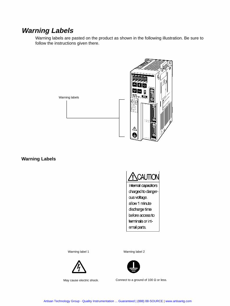
Warning LabelsWarning labels are pasted on the product as shown in the following illustration. Be sure tofollow the instructions given there.
Warning labels
Warning Labels
Warning label 1 Warning label 2
May cause electric shock. Connect to a ground of 100 Ω or less.
Artisan Technology Group - Quality Instrumentation ... Guaranteed | (888) 88-SOURCE | www.artisantg.com

VISUAL INDEX
For users who wish to begin operations quickly.
The OMNUC FND-X-series Position Driver allows motor test operation only by wiring the driverand motor without connecting the controller. Read 3-2 Turning ON Power and Checking Dis-play, properly set the motor model code, and then operate the motor according to 3-8-2 SystemCheck Mode.
Do not connect any load (machines) when performing test operation. Perform test operationonly after confirming that no adverse effects will be caused by test operation.
Initial Operation (Starting)
3-1 Operation Procedure
3-2Turning ON Power and Checking Displays
Function Settings (Parameter Settings)
3-4 Setting Functions: User Parameters (H Parameters)
3-5 Position Control Settings (PTP Parameters)
3-6 Setting Positioning Data (PTP Data, Direct Input)
Trial Operation and Adjustments
3-8-1 Trial Operation Procedure
3-8-2 System Check Mode
3-9-1 Auto-tuning
3-9-2 Manually Adjusting Gain
Troubleshooting
4-4 Protection and Diagnosis
4-5 Troubleshooting
SYSMAC C/CVProgrammable Controller
5-3-1 General ControlCable Specifications
I/O signals
SYSMAC C200H-HX/HG/HEor CQM1 ProgrammableController Section 6 CompoBus/S Specifications
CompoBus/S signals
SRM1-C01/-C02Master Controller
Artisan Technology Group - Quality Instrumentation ... Guaranteed | (888) 88-SOURCE | www.artisantg.com
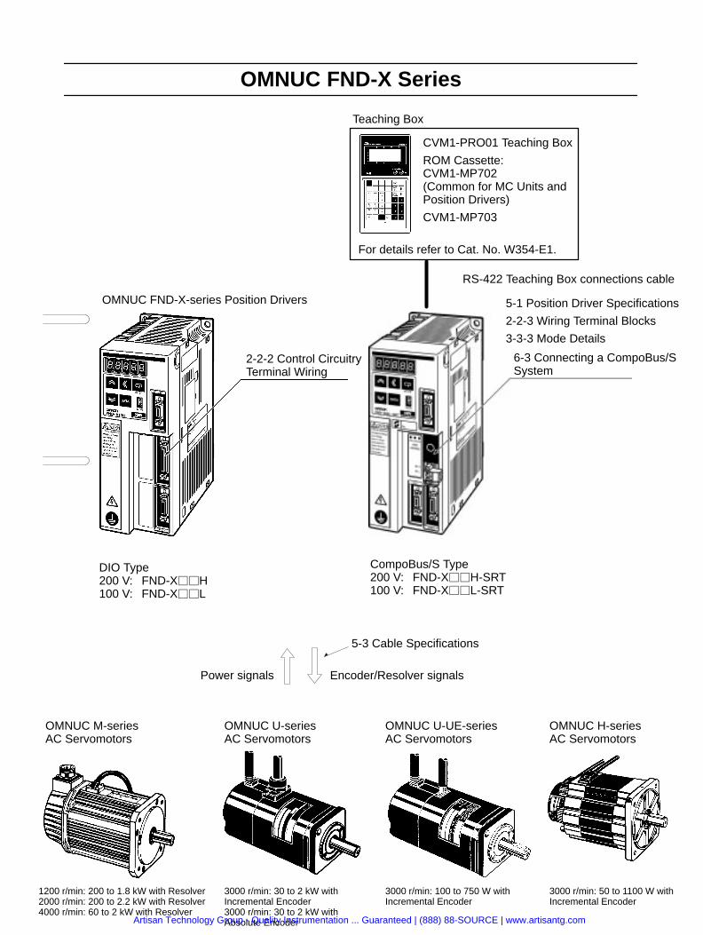
OMNUC FND-X Series
OMNUC FND-X-series Position Drivers
2-2-2 Control CircuitryTerminal Wiring
5-1 Position Driver Specifications
2-2-3 Wiring Terminal Blocks
3-3-3 Mode Details
5-3 Cable Specifications
Encoder/Resolver signalsPower signals
OMNUC M-seriesAC Servomotors
OMNUC U-seriesAC Servomotors
1200 r/min: 200 to 1.8 kW with Resolver2000 r/min: 200 to 2.2 kW with Resolver4000 r/min: 60 to 2 kW with Resolver
3000 r/min: 30 to 2 kW withIncremental Encoder3000 r/min: 30 to 2 kW withAbsolute Encoder
DIO Type200 V: FND-XH100 V: FND-XL
CompoBus/S Type200 V: FND-XH-SRT100 V: FND-XL-SRT
OMNUC U-UE-seriesAC Servomotors
OMNUC H-seriesAC Servomotors
3000 r/min: 100 to 750 W withIncremental Encoder
3000 r/min: 50 to 1100 W withIncremental Encoder
6-3 Connecting a CompoBus/SSystem
Teaching Box
CVM1-PRO01 Teaching Box
ROM Cassette:CVM1-MP702 (Common for MC Units andPosition Drivers)
CVM1-MP703
For details refer to Cat. No. W354-E1.
RS-422 Teaching Box connections cable
Artisan Technology Group - Quality Instrumentation ... Guaranteed | (888) 88-SOURCE | www.artisantg.com

Table of Contents
Chapter 1. Introduction . . . . . . . . . . . . . . . . . . . . . . . . . . . . . . . . . . . . . 1-1 Functions . . . . . . . . . . . . . . . . . . . . . . . . . . . . . . . . . . . . . . . . . . . . . . . . . . . . . . . . . . . . . . . . . . 1-2 Nomenclature and Key Operations . . . . . . . . . . . . . . . . . . . . . . . . . . . . . . . . . . . . . . . . . . . . . . 1-3 Supported Standards and Supporting Models . . . . . . . . . . . . . . . . . . . . . . . . . . . . . . . . . . . . . .
1-3-1 Standards Supported by Position Drivers . . . . . . . . . . . . . . . . . . . . . . . . . . . . . . . . . . . 1-3-2 Standards Supported by AC Servomotors . . . . . . . . . . . . . . . . . . . . . . . . . . . . . . . . . .
Chapter 2. Design and Installation . . . . . . . . . . . . . . . . . . . . . . . . . . . . 2-1 Installation . . . . . . . . . . . . . . . . . . . . . . . . . . . . . . . . . . . . . . . . . . . . . . . . . . . . . . . . . . . . . . . . .
2-1-1 External Dimensions (Unit: mm) . . . . . . . . . . . . . . . . . . . . . . . . . . . . . . . . . . . . . . . . . 2-1-2 Installation Conditions . . . . . . . . . . . . . . . . . . . . . . . . . . . . . . . . . . . . . . . . . . . . . . . . .
2-2 Wiring . . . . . . . . . . . . . . . . . . . . . . . . . . . . . . . . . . . . . . . . . . . . . . . . . . . . . . . . . . . . . . . . . . . . 2-2-1 Overview . . . . . . . . . . . . . . . . . . . . . . . . . . . . . . . . . . . . . . . . . . . . . . . . . . . . . . . . . . . . 2-2-2 Control Circuitry Terminal Wiring . . . . . . . . . . . . . . . . . . . . . . . . . . . . . . . . . . . . . . . . 2-2-3 Wiring Terminal Blocks . . . . . . . . . . . . . . . . . . . . . . . . . . . . . . . . . . . . . . . . . . . . . . . . 2-2-4 Wiring for Noise Resistance . . . . . . . . . . . . . . . . . . . . . . . . . . . . . . . . . . . . . . . . . . . . . 2-2-5 Wiring Products Conforming to EMC Directives . . . . . . . . . . . . . . . . . . . . . . . . . . . . 2-2-6 Peripheral Device Connection Examples . . . . . . . . . . . . . . . . . . . . . . . . . . . . . . . . . . . 2-2-7 Battery Wiring and Encoder Setup for Absolute Encoder . . . . . . . . . . . . . . . . . . . . . .
Chapter 3. Operation . . . . . . . . . . . . . . . . . . . . . . . . . . . . . . . . . . . . . . . 3-1 Operational Procedure . . . . . . . . . . . . . . . . . . . . . . . . . . . . . . . . . . . . . . . . . . . . . . . . . . . . . . . . 3-2 Turning ON Power and Checking Displays . . . . . . . . . . . . . . . . . . . . . . . . . . . . . . . . . . . . . . .
3-2-1 Items to Check Before Turning ON the Power . . . . . . . . . . . . . . . . . . . . . . . . . . . . . . 3-2-2 Turning ON the Power and Checking the Display . . . . . . . . . . . . . . . . . . . . . . . . . . . .
3-3 Using the Display Area . . . . . . . . . . . . . . . . . . . . . . . . . . . . . . . . . . . . . . . . . . . . . . . . . . . . . . . 3-3-1 Key Operations . . . . . . . . . . . . . . . . . . . . . . . . . . . . . . . . . . . . . . . . . . . . . . . . . . . . . . . 3-3-2 Modes and Mode Changes . . . . . . . . . . . . . . . . . . . . . . . . . . . . . . . . . . . . . . . . . . . . . . 3-3-3 Mode Details . . . . . . . . . . . . . . . . . . . . . . . . . . . . . . . . . . . . . . . . . . . . . . . . . . . . . . . . . 3-3-4 CompoBus/S Communications Display and Setting Panel . . . . . . . . . . . . . . . . . . . . .
3-4 Setting Functions: User Parameters (H Parameters) . . . . . . . . . . . . . . . . . . . . . . . . . . . . . . . . . 3-4-1 Setting User Parameters and H Parameters . . . . . . . . . . . . . . . . . . . . . . . . . . . . . . . . . 3-4-2 User Parameter and H Parameter Tables . . . . . . . . . . . . . . . . . . . . . . . . . . . . . . . . . . . 3-4-3 User Parameter and H Parameter Details . . . . . . . . . . . . . . . . . . . . . . . . . . . . . . . . . . .
3-5 Position Control Settings (PTP Parameters) . . . . . . . . . . . . . . . . . . . . . . . . . . . . . . . . . . . . . . . 3-5-1 Setting PTP Parameters (PP-01 to PP-26) . . . . . . . . . . . . . . . . . . . . . . . . . . . . . . . . . . 3-5-2 PTP Parameters (PP-01 to PP-26) . . . . . . . . . . . . . . . . . . . . . . . . . . . . . . . . . . . . . . . . 3-5-3 PTP Parameter Details (PP-01 to PP-26) . . . . . . . . . . . . . . . . . . . . . . . . . . . . . . . . . . .
3-6 Setting Positioning Data (PTP Data, Direct Input) . . . . . . . . . . . . . . . . . . . . . . . . . . . . . . . . . . 3-6-1 Setting PTP Data (When UP-01 is 11 or 12) . . . . . . . . . . . . . . . . . . . . . . . . . . . . . . . . 3-6-2 Setting Direct Input (When UP-01 is 13 or 14) . . . . . . . . . . . . . . . . . . . . . . . . . . . . . . 3-6-3 PTP Data (Pd01jj to Pd64j) . . . . . . . . . . . . . . . . . . . . . . . . . . . . . . . . . . . . . . . . . . . . . 3-6-4 PTP Data Details (Pdjjj) . . . . . . . . . . . . . . . . . . . . . . . . . . . . . . . . . . . . . . . . . . . . . . . .
3-7 Operational Sequence . . . . . . . . . . . . . . . . . . . . . . . . . . . . . . . . . . . . . . . . . . . . . . . . . . . . . . . . 3-7-1 Origin Search . . . . . . . . . . . . . . . . . . . . . . . . . . . . . . . . . . . . . . . . . . . . . . . . . . . . . . . . 3-7-2 Origin Teaching . . . . . . . . . . . . . . . . . . . . . . . . . . . . . . . . . . . . . . . . . . . . . . . . . . . . . . 3-7-3 Teaching . . . . . . . . . . . . . . . . . . . . . . . . . . . . . . . . . . . . . . . . . . . . . . . . . . . . . . . . . . . . 3-7-4 Point Positioning (UP-01: 11 or 12) . . . . . . . . . . . . . . . . . . . . . . . . . . . . . . . . . . . . . . . 3-7-5 Direct Positioning (UP-01: 13 or 14) . . . . . . . . . . . . . . . . . . . . . . . . . . . . . . . . . . . . . .
3-8 Trial Operation . . . . . . . . . . . . . . . . . . . . . . . . . . . . . . . . . . . . . . . . . . . . . . . . . . . . . . . . . . . . . . 3-8-1 Trial Operation Procedure . . . . . . . . . . . . . . . . . . . . . . . . . . . . . . . . . . . . . . . . . . . . . . 3-8-2 System Check Mode . . . . . . . . . . . . . . . . . . . . . . . . . . . . . . . . . . . . . . . . . . . . . . . . . . .
Artisan Technology Group - Quality Instrumentation ... Guaranteed | (888) 88-SOURCE | www.artisantg.com

Table of Contents3-9 Making Adjustments . . . . . . . . . . . . . . . . . . . . . . . . . . . . . . . . . . . . . . . . . . . . . . . . . . . . . . . . .
3-9-1 Auto-tuning . . . . . . . . . . . . . . . . . . . . . . . . . . . . . . . . . . . . . . . . . . . . . . . . . . . . . . . . . . 3-9-2 Manually Adjusting Gain . . . . . . . . . . . . . . . . . . . . . . . . . . . . . . . . . . . . . . . . . . . . . . . 3-9-3 Adjustment Parameter Details . . . . . . . . . . . . . . . . . . . . . . . . . . . . . . . . . . . . . . . . . . .
3-10 Regenerative Energy Absorption . . . . . . . . . . . . . . . . . . . . . . . . . . . . . . . . . . . . . . . . . . . . . . . . 3-10-1 Calculating Regenerative Energy . . . . . . . . . . . . . . . . . . . . . . . . . . . . . . . . . . . . . . . . . 3-10-2 Position Driver Absorbable Regenerative Energy . . . . . . . . . . . . . . . . . . . . . . . . . . . . 3-10-3 Regenerative Energy Absorption by Regeneration Resistor . . . . . . . . . . . . . . . . . . . .
Chapter 4. Application . . . . . . . . . . . . . . . . . . . . . . . . . . . . . . . . . . . . . . 4-1 Monitor Mode . . . . . . . . . . . . . . . . . . . . . . . . . . . . . . . . . . . . . . . . . . . . . . . . . . . . . . . . . . . . . . 4-2 Check Mode . . . . . . . . . . . . . . . . . . . . . . . . . . . . . . . . . . . . . . . . . . . . . . . . . . . . . . . . . . . . . . . .
4-2-1 I/O Signal Status . . . . . . . . . . . . . . . . . . . . . . . . . . . . . . . . . . . . . . . . . . . . . . . . . . . . . . 4-3 Monitor Output . . . . . . . . . . . . . . . . . . . . . . . . . . . . . . . . . . . . . . . . . . . . . . . . . . . . . . . . . . . . . 4-4 Protection and Diagnosis . . . . . . . . . . . . . . . . . . . . . . . . . . . . . . . . . . . . . . . . . . . . . . . . . . . . . .
4-4-1 Alarms . . . . . . . . . . . . . . . . . . . . . . . . . . . . . . . . . . . . . . . . . . . . . . . . . . . . . . . . . . . . . . 4-4-2 Countermeasures to Alarms . . . . . . . . . . . . . . . . . . . . . . . . . . . . . . . . . . . . . . . . . . . . . 4-4-3 CompoBus/S-type Position Driver Protective and Diagnostic Functions . . . . . . . . . . 4-4-4 Overload Characteristics . . . . . . . . . . . . . . . . . . . . . . . . . . . . . . . . . . . . . . . . . . . . . . . . 4-4-5 Alarm Output . . . . . . . . . . . . . . . . . . . . . . . . . . . . . . . . . . . . . . . . . . . . . . . . . . . . . . . .
4-5 Troubleshooting . . . . . . . . . . . . . . . . . . . . . . . . . . . . . . . . . . . . . . . . . . . . . . . . . . . . . . . . . . . . . 4-5-1 Preliminary Inspection . . . . . . . . . . . . . . . . . . . . . . . . . . . . . . . . . . . . . . . . . . . . . . . . . 4-5-2 Precautions . . . . . . . . . . . . . . . . . . . . . . . . . . . . . . . . . . . . . . . . . . . . . . . . . . . . . . . . . . 4-5-3 Replacing the Position Driver and the Motor . . . . . . . . . . . . . . . . . . . . . . . . . . . . . . . . 4-5-4 Troubleshooting . . . . . . . . . . . . . . . . . . . . . . . . . . . . . . . . . . . . . . . . . . . . . . . . . . . . . .
4-6 Periodic Maintenance . . . . . . . . . . . . . . . . . . . . . . . . . . . . . . . . . . . . . . . . . . . . . . . . . . . . . . . .
Chapter 5. Specifications . . . . . . . . . . . . . . . . . . . . . . . . . . . . . . . . . . . . 5-1 Position Driver Specifications . . . . . . . . . . . . . . . . . . . . . . . . . . . . . . . . . . . . . . . . . . . . . . . . . .
5-1-1 General Specifications (Common to DIO, CompoBus/S) . . . . . . . . . . . . . . . . . . . . . . 5-1-2 Performance Specifications . . . . . . . . . . . . . . . . . . . . . . . . . . . . . . . . . . . . . . . . . . . . . 5-1-3 I/O Specifications . . . . . . . . . . . . . . . . . . . . . . . . . . . . . . . . . . . . . . . . . . . . . . . . . . . . .
5-2 Servomotor Specifications . . . . . . . . . . . . . . . . . . . . . . . . . . . . . . . . . . . . . . . . . . . . . . . . . . . . . 5-2-1 U-series 30-W to 750-W Servomotors (INC/ABS) . . . . . . . . . . . . . . . . . . . . . . . . . . . 5-2-2 U-UE-series Servomotors . . . . . . . . . . . . . . . . . . . . . . . . . . . . . . . . . . . . . . . . . . . . . . . 5-2-3 U-series 1-kW to 2-kW Servomotors (INC/ABS) . . . . . . . . . . . . . . . . . . . . . . . . . . . . 5-2-4 H-series Servomotors . . . . . . . . . . . . . . . . . . . . . . . . . . . . . . . . . . . . . . . . . . . . . . . . . . 5-2-5 M-series Servomotors . . . . . . . . . . . . . . . . . . . . . . . . . . . . . . . . . . . . . . . . . . . . . . . . . .
5-3 Cable Specifications . . . . . . . . . . . . . . . . . . . . . . . . . . . . . . . . . . . . . . . . . . . . . . . . . . . . . . . . . 5-3-1 General Control Cables (DIO Position Drivers Only) . . . . . . . . . . . . . . . . . . . . . . . . . 5-3-2 Connector Terminal Board Conversion Unit Cables (DIO Position Drivers Only) . . . 5-3-3 External Control Signal Connecting Cables (CompoBus/S Position Drivers Only) . . 5-3-4 Encoder Cables . . . . . . . . . . . . . . . . . . . . . . . . . . . . . . . . . . . . . . . . . . . . . . . . . . . . . . . 5-3-5 Resolver Cables . . . . . . . . . . . . . . . . . . . . . . . . . . . . . . . . . . . . . . . . . . . . . . . . . . . . . . 5-3-6 Power Cables . . . . . . . . . . . . . . . . . . . . . . . . . . . . . . . . . . . . . . . . . . . . . . . . . . . . . . . .
Chapter 6. CompoBus/S Specifications . . . . . . . . . . . . . . . . . . . . . . . . . 6-1 CompoBus/S Configuration Requirements . . . . . . . . . . . . . . . . . . . . . . . . . . . . . . . . . . . . . . . . 6-2 CompoBus/S Communications Specifications . . . . . . . . . . . . . . . . . . . . . . . . . . . . . . . . . . . . . 6-3 Connecting a CompoBus/S System . . . . . . . . . . . . . . . . . . . . . . . . . . . . . . . . . . . . . . . . . . . . . .
Artisan Technology Group - Quality Instrumentation ... Guaranteed | (888) 88-SOURCE | www.artisantg.com

Table of Contents
Chapter 7. Appendices . . . . . . . . . . . . . . . . . . . . . . . . . . . . . . . . . . . . . . 7-1 Standard Models . . . . . . . . . . . . . . . . . . . . . . . . . . . . . . . . . . . . . . . . . . . . . . . . . . . . . . . . . . . . 7-2 Parameter Settings Tables . . . . . . . . . . . . . . . . . . . . . . . . . . . . . . . . . . . . . . . . . . . . . . . . . . . . .
Revision History . . . . . . . . . . . . . . . . . . . . . . . . . . . . . . . . .
Artisan Technology Group - Quality Instrumentation ... Guaranteed | (888) 88-SOURCE | www.artisantg.com

Chapter 1
Introduction
1-1 Functions
1-2 Nomenclature and Key Operations
1-3 Supported Standards and Supporting Models
1
Artisan Technology Group - Quality Instrumentation ... Guaranteed | (888) 88-SOURCE | www.artisantg.com
1-2
1-1 Functions
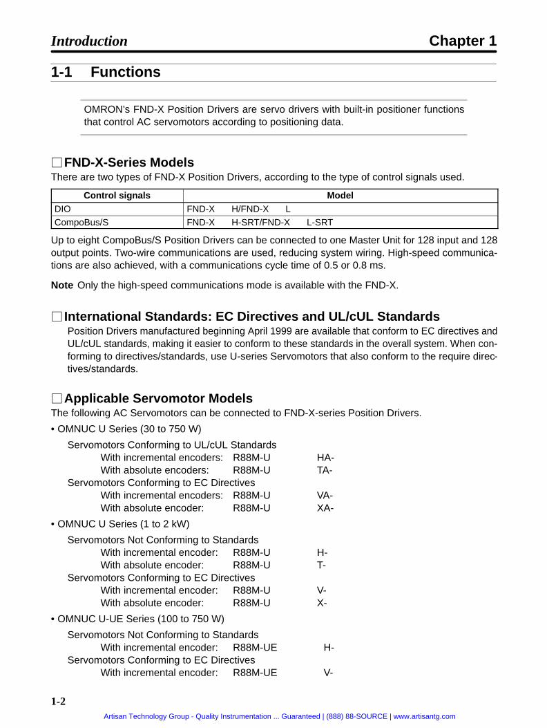
OMRON’s FND-X Position Drivers are servo drivers with built-in positioner functionsthat control AC servomotors according to positioning data.
FND-X-Series ModelsThere are two types of FND-X Position Drivers, according to the type of control signals used.
Control signals ModelDIO FND-XH/FND-XL
CompoBus/S FND-XH-SRT/FND-XL-SRT
Up to eight CompoBus/S Position Drivers can be connected to one Master Unit for 128 input and 128output points. Two-wire communications are used, reducing system wiring. High-speed communica-tions are also achieved, with a communications cycle time of 0.5 or 0.8 ms.
Note Only the high-speed communications mode is available with the FND-X.
International Standards: EC Directives and UL/cUL StandardsPosition Drivers manufactured beginning April 1999 are available that conform to EC directives andUL/cUL standards, making it easier to conform to these standards in the overall system. When con-forming to directives/standards, use U-series Servomotors that also conform to the require direc-tives/standards.
Applicable Servomotor ModelsThe following AC Servomotors can be connected to FND-X-series Position Drivers.
• OMNUC U Series (30 to 750 W)
Servomotors Conforming to UL/cUL StandardsWith incremental encoders: R88M-UHA-With absolute encoders: R88M-UTA-
Servomotors Conforming to EC DirectivesWith incremental encoders: R88M-UVA-With absolute encoder: R88M-UXA-
• OMNUC U Series (1 to 2 kW)
Servomotors Not Conforming to StandardsWith incremental encoder: R88M-UH-With absolute encoder: R88M-UT-
Servomotors Conforming to EC DirectivesWith incremental encoder: R88M-UV-With absolute encoder: R88M-UX-
• OMNUC U-UE Series (100 to 750 W)
Servomotors Not Conforming to StandardsWith incremental encoder: R88M-UEH-
Servomotors Conforming to EC DirectivesWith incremental encoder: R88M-UEV-
Introduction Chapter 1
Artisan Technology Group - Quality Instrumentation ... Guaranteed | (888) 88-SOURCE | www.artisantg.com

1-3
• OMNUC H (50 to 1,100 W) Series (with incremental encoder): R88M-H-
• OMNUC M (60 to 2,200 W) Series (with resolver): R88M-M-
Note H-series and M-series models do not conform to the EC Directives and UL/cUL standards.
• The following models are available with different output capacities, and are arranged according to in-put power supply.
Position Driver and AC Servomotor Combinations
Position Driver Applicable AC ServomotorInput power
supplyModel Series Model Output
capacityRated r/min
Single-phase/ (
FND-X06H- U R88M-U03030A 30 W 3,000 r/ming200/240 (170 to264) VAC at
R88M-U05030A 50 W
,
264) VAC at50/60 Hz R88M-U10030A 100 W50/60 Hz
U-UE R88M-UE10030-S1 100 W 3,000 r/minH R88M-H05030 50 W 3,000 r/min
R88M-H10030 100 W
,
FND-X12H- U R88M-U20030A 200 W 3,000 r/min
R88M-U40030A 400 W
,
U-UE R88M-UE20030-S1 200 W 3,000 r/min
R88M-UE40030-S1 400 W
,
H R88M-H20030 200 W 3,000 r/min
R88M-H30030 300 W
,
M R88M-M06040 60 W 4,000 r/min
R88M-M12040 120 W
,
R88M-M20040 200 WR88M-M40040 400 W
R88M-M20020 200 W 2,000 r/min
R88M-M40020 400 W
,
R88M-M20012 200 W 1,200 r/min
R88M-M40012 400 W
,
FND-X25H- U R88M-U75030A 750 W 3,000 r/min
R88M-U1K030 1000 W
,
U-UE R88M-UE75030-S1 750 W 3,000 r/minH R88M-H50030 500 W 3,000 r/min
R88M-H75030 750 W
,
R88M-H1K130 1100 WM R88M-M70040 700 W 4,000 r/min
R88M-M1K140 1100 W
,
R88M-M70020 700 W 2,000 r/min
R88M-M1K120 1100 W
,
R88M-M70012 700 W 1,200 r/min
Introduction Chapter 1
Artisan Technology Group - Quality Instrumentation ... Guaranteed | (888) 88-SOURCE | www.artisantg.com

1-4
Position Driver Applicable AC ServomotorInput power
supplyRated r/minOutput
capacityModelSeriesModel
Three-phase200/240 (1 0
FND-X50H- U R88M-U1K530 1500 W 3000 r/min200/240 (170 to264) VAC at
R88M-U2K030 2000 W264) VAC at50/60 Hz M R88M-M2K040 2000 W 4000 r/min50/60 Hz
R88M-M1K820 1800 W 2000 r/min
R88M-M2K220 2200 WR88M-M1K112 1100 W 1200 r/min
R88M-M1K412 1400 W
R88M-M1K812 1800 WSingle-phase
/ (FND-X06L- U R88M-U03030A 30 W 3,000 r/ming
100/115 (85 to127) VAC at
R88M-U05030A 50 W
,
127) VAC at50/60 Hz R88M-U10030A 100 W50/60 Hz
U-UE R88M-UE10030-S1 100 W 3,000 r/minH R88M-H05030 50 W 3,000 r/min
R88M-H10030 100 W
,
FND-X12L- U R88M-U20030A 200 W 3,000 r/minU-UE R88M-UE20030-S1 200 W 3,000 r/minH R88M-H20030 200 W 3,000 r/minM R88M-M06040 60 W 4,000 r/min
R88M-M12040 120 W
,
R88M-M20040 200 WR88M-M20020 200 W 2,000 r/min
R88M-M20012 200 W 1,200 r/min
Note 1. Even when a U-series or U-UE-series Servomotor is used in combination with a100-VAC-in-put Position Driver, a 200-VAC Servomotor must be used. A 100-VAC Servomotor cannot beconnected.
Note 2. Straight-axis servomotors are available either with or without a key or brake. In the abovetable, the Servomotors have the following features.U-series Straight axis without brake, without keyU-series UE models Straight axis without brake, with key (not available without key)H-series Straight axis without brake, with keyM-series Straight axis without brake, with key (“A” cut for small-capacity)
Note 3. Motor control is enabled by setting the user parameter UP-02 of the Position Driver.
Note 4. U-series UE-type and H-series Servomotors can be used only with Position Driver softwareversion 4.01 (September 1997) or later.U-series 1-kW to 2-kW Servomotors and M-series 1.1-kW to 2.2-kW Servomotors can beused only with Position Driver software version 4.04 (April 1999) or later.
Introduction Chapter 1
Artisan Technology Group - Quality Instrumentation ... Guaranteed | (888) 88-SOURCE | www.artisantg.com

1-5
Servomotor Features and Selection StandardsAny FND-X-series Position Driver can be freely selected according to the application. When making theselection, take the following points into consideration.
Servomotor Features
U/UE Series Compact size, high-speed response
High resolution (except for UE type)
Absolute encoder system can be configured (except for UE type).
H Series High resolution
High application load inertia (less than 10 times the rotary inertia)
Usable in systems with comparatively low mechanical rigidity.
M Series High application load inertia (less than 10 times the rotary inertia)
Usable in systems with comparatively low mechanical rigidity.
High output torque in a low-rotation motor
Up to a maximum of 50 meters between Servomotor and Servo Driver.
Motor Selection Standards (Reference)Drive system type Low inertia High inertia
Ball screw direct connection U, U-UE, H, M U, U-UE, H, M
Turntable direct connection U, U-UE, H, M U, U-UE, H, M
Feeder (direct connection) U, U-UE, H, M U, U-UE, H, M
Harmonic drive U, U-UE, H, M H, M
Chain drive U, U-UE, H, M H, M
Belt drive U, U-UE, H, M H, M
Rack & pinion U, U-UE, H, M H, M
Note “Low inertia” means that the motor axis conversion inertia is approximately 0 to 5 times the rotaryinertia for H-series and M-series Servomotors, and approximately 0 to 15 times the rotary inertiafor U-series and U-series UE-type Servomotors.“High inertia” means that the motor axis conversion inertia is approximately 5 to 10 times therotary inertia for H-series and M-series Servomotors, and approximately 15 to 30 times the rotaryinertia for U-series and U-series UE-type Servomotors.
Position Control Functions
Pulse Rate Setting FunctionPulse rate setting makes it possible to set positioning data (i.e., positions and speeds) according to themechanical axis.
Introduction Chapter 1
Artisan Technology Group - Quality Instrumentation ... Guaranteed | (888) 88-SOURCE | www.artisantg.com

1-6
Control ModeThe following four types of control modes are available to the Position Driver: PTP control and feedercontrol modes with the internal point data preset in the Position Driver and these same modes with di-rect I/O signal input.
Internal Point Data• A maximum of 64 points of data (Pd01 to Pd64) can be set internally in the Position Driver.
• Positions can be set within a range between –39,999,999 to 39,999,999 with the absolute or incre-mental value specified.
Positioning Data Instruction by Direct InputEight-point input and input timing signals are used to input position data and speed data within the fol-lowing ranges into the Position Driver.
Position Setting Range: –39,999,999 to 39,999,999 (with incremental or absolute setting)
Speed Setting Range: 1% to 100% (override setting with respect to reference speed)
Position Compensation FunctionThis function executes backlash compensation when PTP control is used, and slip compensation whenfeeder control is used.
Acceleration/Deceleration Function• Either linear (trapezoidal) acceleration or deceleration time or S-shaped (primary low-pass filter) ac-
celeration or deceleration time can be selected. In addition, different times can be set for accelerationand deceleration.
• The S-shaped acceleration/deceleration function makes it possible, for example, to start up convey-ors smoothly or achieve feeder control with minimal feeder slippage.
Stop Methods• The stop method for when the STOP signal is turned OFF can be selected with PP-24.
Free-running stop: Motor power supply turned OFF.
Deceleration stop: Servo-lock after the operation decelerates to a stop in preset time.
Error counter reset stop: Servo-lock after an immediate deceleration to a stop with the errorcounter reset.
• The stop method of the Position Driver in the case of overrun or software limit signal detection can beselected with PP-25.
Overrun: Servo free-running stop with the alarm AL38 turned ON or servo-lock stop.
Software limit detection: Servo-lock stop with or without alarms AL34 and AL35 turned ON.
Teaching Functions
Position TeachingThe Position Driver has a teaching function that enables the Position Driver stop the mechanical axiswith an external force by going into servo-free status or JOG operation and to take up the stop positiondata automatically as part of PTP data.
Introduction Chapter 1
Artisan Technology Group - Quality Instrumentation ... Guaranteed | (888) 88-SOURCE | www.artisantg.com

1-7
Mechanical Origin TeachingAn optional position can be specified as the mechanical origin by moving the position to the mechanicalorigin and teaching after the completion of origin search.
Motor Control Functions
Motor Type and Capacity Selection by Motor CodeA motor type and capacity can be selected by setting UP-02 to the corresponding motor code.
Auto-tuning Function• The Position Driver has an auto-tuning function. If a machine and motor are connected to the Position
Driver, this function makes it possible to check the capacity and characteristics of the machine load byturning the motor and enables the automatic gain control of the Position Driver according to the capac-ity and characteristics of the machine load.
• The auto-tuning function makes it possible to save system startup time.
Programming Devices
Teaching Box: CVM1-PRO01 + ROM CassetteThe Teaching Box provides for easy operation, including the following:
Position Driver status monitoringParameter editing and transferTeachingJoggingPositioning to specified pointsAutotuning
Note Refer to the CVM1-PRO01 Teaching Box Operation Manual (W354) for more information.
OMNUC FND-X Series Monitoring SoftwareThe OMNUC FND-X Series Monitoring Software runs on an IBM PC/AT or compatible computer and pro-vides for easy operation, including the following:
Position Driver status monitoringParameter editing and transferSpeed and current waveform displaysAutotuning
Monitor Functions
Monitor ModeThe motor speed, present value, reference value, position deviation value, machine speed, motor cur-rent, effective load factor, electronic thermal value, electrical angle, and regenerative absorption ratecan be monitored on the front panel of the Position Driver in this mode.
Check ModeThe I/O signal status, alarm details, alarm history, and software version are displayed on the front panelof the Position Driver in this mode.
Introduction Chapter 1
Artisan Technology Group - Quality Instrumentation ... Guaranteed | (888) 88-SOURCE | www.artisantg.com

1-8
Protection and Self-diagnostic Functions
Hardware ProtectionThe Position Driver is protected from overcurrent, overvoltage, low voltage, abnormal power, clock fail-ure, overcurrent (soft), speed amplifier saturation, and overload damage.
Mechanical System ProtectionThe mechanical system is protected from damage resulting from overspeed, error counter overflows,soft limit overflows, coordinate counter overflows, or overrun.
Parameter Setting-related ErrorsThe Position Driver detects parameter setting errors.
Detector-related ErrorsResolver wire burnout, resolver failure, encoder wire disconnection, encoder communications failure,absolute encoder backup failure, absolute encoder checksum failure, absolute encoder battery failure,absolute encoder absolute failure, absolute encoder overspeed failure, encoder data failure, and en-coder initialization failure.
Position-related ErrorsBCD data, indefinite PV, and PTP data non-setting errors.
Test Functions
Motor Test FunctionThe Position Driver has a motor test function that makes it possible to easily check whether a motor isconnected to the Position Driver. When this function is enabled, the motor rotation direction can be con-trolled with the operation keys and the motor speed can be set in UP-29. The motor speed is set to50 r/min before shipping.
Sequential Output Test FunctionThe Position Driver has a sequential output test function that makes it possible to easily check whether ahost controller is connected to the Position Driver. This function makes it possible to turn any outputterminal ON or OFF with the operation keys.
Introduction Chapter 1
Artisan Technology Group - Quality Instrumentation ... Guaranteed | (888) 88-SOURCE | www.artisantg.com
1-9
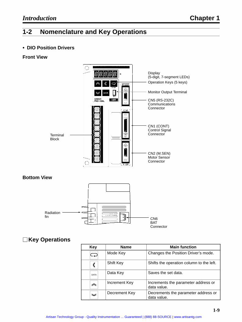
1-2 Nomenclature and Key Operations
DIO Position Drivers
Front View
Display (5-digit, 7-segment LEDs)Operation Keys (5 keys)
Monitor Output Terminal
CN5 (RS-232C)CommunicationsConnector
TerminalBlock
CN1 (CONT)Control SignalConnector
CN2 (M.SEN)Motor SensorConnector
Bottom View
Radiationfin CN6
BATConnector
Key OperationsKey Name Main function
Mode Key Changes the Position Driver’s mode.
Shift Key Shifts the operation column to the left.
DATAData Key Saves the set data.
Increment Key Increments the parameter address ordata value.
Decrement Key Decrements the parameter address ordata value.
Introduction Chapter 1
Artisan Technology Group - Quality Instrumentation ... Guaranteed | (888) 88-SOURCE | www.artisantg.com

1-10
CompoBus/S Position Drivers
Front View
Display (5-digit, 7-segment LEDs)Operation Keys (5 keys)
Monitor Output Terminal
CN5 (RS-232C)CommunicationsConnector
TerminalBlock
CN1 (CONT)Control SignalConnector
CN2 (M.SEN)Motor SensorConnector
CN4 (LIMIT)External controlsignal connector
Node Address Setting Switch
Bottom View
Radiation fin
CN6BAT Connector
Key OperationsKey Name Main function
Mode Key Changes the Position Driver’s mode.
Shift Key Shifts the operation column to the left.
DATAData Key Saves the set data.
Increment Key Increments the parameter address ordata value.
Decrement Key Decrements the parameter address ordata value.
Introduction Chapter 1
Artisan Technology Group - Quality Instrumentation ... Guaranteed | (888) 88-SOURCE | www.artisantg.com

1-11
1-3 Supported Standards and Supporting Models
1-3-1 Standards Supported by Position DriversStandard Supported standard File No. Remarks
UL/cUL UL508C E179149 Electrical power conversion devicesEC Low-voltage Directive EN50178 --- Industrial product specifications
EMC Directive EN55011 class Agroup 1
--- Radio interference limits and measurementmethods for radio frequency devices for in-dustrial, scientific, and medical applications
EN61000-4 --- Electromagnetic compatibility and immunity
Note All Position Drivers in the FND-X Series conform to UL/cUL standards and EC directives.
1-3-2 Standards Supported by AC ServomotorsStandard Supported standard File No. Remarks
UL/cUL UL1004 E179189 Electric motorscUL C22.2 No. 100 E179189 Motors and generators
EC Low-voltage Directive IEC34-1, -5, -8, -9 --- Rotating electric devicesEMC Directive EN55011 class A
group 1--- Radio interference limits and measurement
methods for radio frequency devices for in-dustrial, scientific, and medical applications
EN61000-4 --- Electromagnetic compatibility and immunity
Servomotors Conforming to UL/cUL StandardsPower supply AC Servomotors Encoder
200 VAC R88M-U30HA- (30 to 750 W) Incremental encoder
200 VAC R88M-U30TA- (30 to 750 W) Absolute encoder
Note Servomotors manufactured beginning in May 1998 conform to UL/cUL standards.
Servomotors Conforming EC DirectivesPower supply AC Servomotors Encoder
200 VAC R88M-U30VA- (30 to 750 W) Incremental encoder
200 VAC R88M-U30XA- (30 to 750 W) Absolute encoder
200 VAC R88M-UE30V- (100 to 750 W) Incremental encoder
200 VAC R88M-U30V- (1 to 2 kW) Incremental encoder
200 VAC R88M-U30X- (1 to 2 kW) Absolute encoder
Note The Servomotors must be wired as described in 2-2 Wiring to conform to the EMC Directive.
Introduction Chapter 1
Artisan Technology Group - Quality Instrumentation ... Guaranteed | (888) 88-SOURCE | www.artisantg.com

Chapter 2
Design and Installation
2-1 Installation
2-2 Wiring
2
Artisan Technology Group - Quality Instrumentation ... Guaranteed | (888) 88-SOURCE | www.artisantg.com

2-2
2-1 Installation
2-1-1 External Dimensions (Unit: mm)
DIO and CompoBus/S Position Drivers
200-VAC FND-X06H-/-X12H-100-VAC FND-X06L-/-X12L-
Mounting Dimensions
Three, 6 dia. Three, M5
200-VAC FND-X25H-
Mounting Dimensions
Three, 6 dia. Three, M5
Design and Installation Chapter 2
Artisan Technology Group - Quality Instrumentation ... Guaranteed | (888) 88-SOURCE | www.artisantg.com

2-3
200-VAC FND-X50H-
Mounting Dimensions
Four, 6 dia.
Four, M5
Design and Installation Chapter 2
Artisan Technology Group - Quality Instrumentation ... Guaranteed | (888) 88-SOURCE | www.artisantg.com

2-4
OMNUC U-Series AC Servomotors with Incremental Encoders(U-INC 30 to 750 W) Conforming to UL/cUL
30-W/50-W/100-W Standard Models (Without Brakes): R88M-U03030HA, R88M-U05030HA, R88M-U10030HA
Two, 4.3 dia.Four, R3.7
6h6
dia.
30h7
dia
.46 dia.
Encoder adapter
Motor plug
14 dia.
300±30
35
6.5 6300±30
9.5
2.55
17
33
LL 25
L
6
18
40
40
30-W/50-W/100-W Models with Brakes: R88M-U03030HA-B, R88M-U05030HA-B, R88M-U10030HA-B
Two, 4.3 dia. Four, R3.7
6h6
dia.
30h7
dia
.
46 dia.
Encoder adapter
Motor plug
14 dia.
300±30
17
35
6.5
300±30
9.5
2.55
25LL
L
33 LB
4
21
40
40
Standard Models (Without Brakes)Model L LL S
R88M-U03030HA 94.5 69.5 6
R88M-U05030HA 102.0 77.0 6
R88M-U10030HA 119.5 94.5 8
Models with BrakesModel L LL LB S
R88M-U03030HA-B 126 101 31.5 6
R88M-U05030HA-B 133.5 108.5 31.5 6
R88M-U10030HA-B 160 135 40.5 8
Design and Installation Chapter 2
Artisan Technology Group - Quality Instrumentation ... Guaranteed | (888) 88-SOURCE | www.artisantg.com
2-5
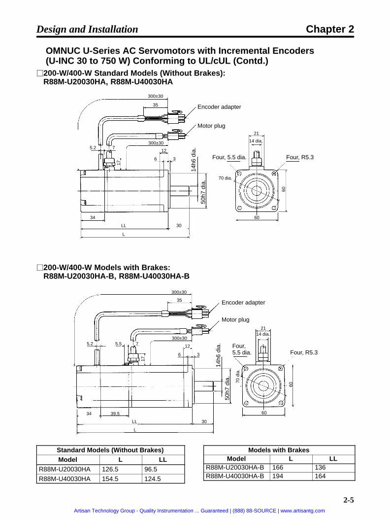
OMNUC U-Series AC Servomotors with Incremental Encoders(U-INC 30 to 750 W) Conforming to UL/cUL (Contd.)
200-W/400-W Standard Models (Without Brakes): R88M-U20030HA, R88M-U40030HA
Four, 5.5 dia. Four, R5.3
14h6
dia
.
50h7
dia
. 70 dia.
Encoder adapter
Motor plug
14 dia.
300±30
17
35
300±305.2 7
12
6 3
34
LL 30
L
21
60
60
200-W/400-W Models with Brakes: R88M-U20030HA-B, R88M-U40030HA-B
Four,5.5 dia. Four, R5.3
14h6
dia
.
50h7
dia
.
Encoder adapter
Motor plug
70 d
ia.
14 dia.
300±30
17
35
5.2 5.5 7300±30
12
6 3
34 39.5
LL 30
L
21
60
60
Standard Models (Without Brakes)Model L LL
R88M-U20030HA 126.5 96.5
R88M-U40030HA 154.5 124.5
Models with BrakesModel L LL
R88M-U20030HA-B 166 136R88M-U40030HA-B 194 164
Design and Installation Chapter 2
Artisan Technology Group - Quality Instrumentation ... Guaranteed | (888) 88-SOURCE | www.artisantg.com

2-6
OMNUC U-Series AC Servomotors with Incremental Encoders(U-INC 30 to 750 W) Conforming to UL/cUL (Contd.)
750-W Standard Models (Without Brakes): R88M-U75030HA
Four, 7 dia.Four, R8.2
16h6
dia
.
70h7
dia
.
Encoder adapter
Motor plug
90 d
ia.
14 dia.
300±30
1735
300±3085.2
8 3
15
35
34
145 40
185
21
80
80
750-W Models with Brakes: R88M-U75030HA-B
Four, 7 dia.Four, R8.2
16h6
dia
.
70h7
dia
.
Encoder adapter
Motor plug
90 d
ia.
14 dia.
300±30
17
35
300±3085.2
8 3
15
35
34 44.5
189.5 40
229.5
21
80
80
Design and Installation Chapter 2
Artisan Technology Group - Quality Instrumentation ... Guaranteed | (888) 88-SOURCE | www.artisantg.com

2-7
OMNUC U-Series AC Servomotors with Incremental Encoders(U-INC 30 to 750 W) Conforming to EC Directives
30-W/50-W/100-W Standard Models (Without Brakes): R88M-U03030VA-S1, R88M-U05030VA-S1, R88M-U10030VA-S1
Two, 4.3 dia. Four, R3.7
Sh6
dia
.
30h7
dia
.
14 dia.
46 d
ia.
30-W/50-W/100-W Models with Brakes: R88M-U03030VA-BS1, R88M-U05030VA-BS1, R88M-U10030VA-BS1
Two, 4.3 dia.Four, R3.7
Sh6
dia
.
30h7
dia
.
14 dia.
46 d
ia.
Standard Models (Without Brakes)Model L LL S
R88M-U03030VA-S1 94.5 69.5 6
R88M-U05030VA-S1 102.0 77.0 6
R88M-U10030VA-S1 119.5 94.5 8
Models with BrakesModel L LL LB S
R88M-U03030VA-BS1 126 101 31.5 6
R88M-U05030VA-BS1 133.5 108.5 31.5 6
R88M-U10030VA-BS1 160 135 40.5 8
Design and Installation Chapter 2
Artisan Technology Group - Quality Instrumentation ... Guaranteed | (888) 88-SOURCE | www.artisantg.com

2-8
OMNUC U-Series AC Servomotors with Incremental Encoders(U-INC 30 to 750 W) Conforming to EC Directives (Contd.)
200-W/400-W Standard Models (Without Brakes): R88M-U20030VA-S1, R88M-U40030VA-S1
Four, 5.5 dia. Four, R5.3
14h6
dia
.
50h7
dia
.
14 dia.
70 d
ia.
200-W/400-W Models with Brakes: R88M-U20030VA-BS1, R88M-U40030VA-BS1
Four, 5.5 dia. Four, R5.3
14h6
dia
.
50h7
dia
.
14 dia.
70 d
ia.
Standard Models (Without Brakes)Model L LL
R88M-U20030VA-S1 126.5 96.5
R88M-U40030VA-S1 154.5 124.5
Models with BrakesModel L LL
R88M-U20030VA-BS1 166 136R88M-U40030VA-BS1 194 164
Design and Installation Chapter 2
Artisan Technology Group - Quality Instrumentation ... Guaranteed | (888) 88-SOURCE | www.artisantg.com

2-9
OMNUC U-Series AC Servomotors with Incremental Encoders(U-INC 30 to 750 W) Conforming to EC Directives (Contd.)
750-W Standard Models (Without Brakes): R88M-U75030VA-S1
Four, 7 dia.Four, R8.2
16h6
dia
.
70h7
dia
.
14 dia.
90 d
ia.
750-W Models with Brakes: R88M-U75030VA-BS1
Four, 7 dia. Four, R8.2
16h6
dia
.
70h7
dia
.
14 dia.
90 d
ia.
Design and Installation Chapter 2
Artisan Technology Group - Quality Instrumentation ... Guaranteed | (888) 88-SOURCE | www.artisantg.com

2-10
OMNUC U-Series AC Servomotors with Absolute Encoders(U-ABS 30 to 750 W) Conforming to UL/cUL
30-W/50-W/100-W Standard Models (Without Brakes):R88M-U03030TA, R88M-U05030TA, R88M-U10030TA
Two, 4.3 dia. Four, R3.7
46 dia.
14 dia.
Sh6 dia.
30h7 dia.
Encoder adapter
Motor plug
53 dia.
30-W/50-W/100-W Models with Brakes:R88M-U03030TA-B, R88M-U05030TA-B, R88M-U10030TA-B
Two, 4.3 dia.Four, R3.7
46 dia.
Sh6 dia.
30h7 dia.
14 dia.
Encoder adapter
Motor plug
53 dia.
Standard Models (Without Brakes)Model L LL S
R88M-U03030TA 117.5 92.5 6
R88M-U05030TA 125 100 6
R88M-U10030TA 142.5 117.5 8
Models with BrakesModel L LL LB S
R88M-U03030TA-B 149 124 31.5 6
R88M-U05030TA-B 156.5 131.5 31.5 6
R88M-U10030TA-B 183 158 40.5 8
Design and Installation Chapter 2
Artisan Technology Group - Quality Instrumentation ... Guaranteed | (888) 88-SOURCE | www.artisantg.com

2-11
OMNUC U-Series AC Servomotors with Absolute Encoders(U-ABS 30 to 750 W) Conforming to UL/cUL (Contd.)
200-W/400-W Standard Models (Without Brakes):R88M-U20030TA, R88M-U40030TA
Four, R5.3Four, 5.5.dia.
70 dia.
14h6 dia.
50h7 dia.
14 dia.
Encoder adapter
Motor plug
200-W/400-W Models with Brakes:R88M-U20030TA-B, R88M-U40030TA-B
Four, R5.3Four, 5.5.dia.
70 dia.
14h6 dia.
50h7 dia.
14 dia.
Encoder adapter
Motor plug
Standard Models (Without Brakes)Model L LL
R88M-U20030TA 147.5 117.5
R88M-U40030TA 175.5 145.5
Models with BrakesModel L LL
R88M-U20030TA-B 187 157
R88M-U40030TA-B 215 185
Design and Installation Chapter 2
Artisan Technology Group - Quality Instrumentation ... Guaranteed | (888) 88-SOURCE | www.artisantg.com

2-12
OMNUC U-Series AC Servomotors with Absolute Encoders(U-ABS 30 to 750 W) Conforming to UL/cUL (Contd.)
750-W Standard Models (Without Brakes): R88M-U75030TA
Four, R8.2Four, 7 dia.
90 dia.16h6 dia.
70h7 dia.
14 dia.
Encoder adapter
Motor plug
750-W Models with Brakes: R88M-U75030TA-B
Four, R8.2Four, 7 dia.
90 dia.16h6 dia.
70h7 dia.
14 dia.
Encoder adapter
Motor plug
Design and Installation Chapter 2
Artisan Technology Group - Quality Instrumentation ... Guaranteed | (888) 88-SOURCE | www.artisantg.com

2-13
OMNUC U-Series AC Servomotors with Absolute Encoders(U-ABS 30 to 750 W) Conforming to EC Directives
30-W/50-W/100-W Standard Models (Without Brakes):R88M-U03030XA-S1, R88M-U05030XA-S1, R88M-U10030XA-S1
Two, 4.3 dia. Four, R3.7
Sh6
dia
.
30h7
dia
. 46 dia.
14 dia.
53 dia.
30-W/50-W/100-W Models with Brakes:R88M-U03030XA-BS1, R88M-U05030XA-BS1, R88M-U10030XA-BS1
Two, 4.3 dia. Four, R3.7
Sh6
dia
.
30h7
dia
. 46 dia.
14 dia.
53 dia.
Standard Models (Without Brakes)Model L LL S
R88M-U03030XA-S1 117.5 92.5 6
R88M-U05030XA-S1 125 100 6
R88M-U10030XA-S1 142.5 117.5 8
Models with BrakesModel L LL LB S
R88M-U03030XA-BS1 149 124 31.5 6
R88M-U05030XA-BS1 156.5 131.5 31.5 6
R88M-U10030XA-BS1 183 158 40.5 8
Design and Installation Chapter 2
Artisan Technology Group - Quality Instrumentation ... Guaranteed | (888) 88-SOURCE | www.artisantg.com

2-14
OMNUC U-Series AC Servomotors with Absolute Encoders(U-ABS 30 to 750 W) Conforming to EC Directives (Contd.)
200-W/400-W Standard Models (Without Brakes):R88M-U20030XA-S1, R88M-U40030XA-S1
Four, 5.5 dia. Four, R5.3
14h6
dia
.
50h7
dia
. 70 dia.
14 dia.
200-W/400-W Models with Brakes:R88M-U20030XA-BS1, R88M-U40030XA-BS1
Four, 5.5 dia. Four, R5.3
14h6
dia
.
50h7
dia
. 70 dia.
14 dia.
Standard Models (Without Brakes)Model L LL
R88M-U20030XA-S1 147.5 117.5
R88M-U40030XA-S1 175.5 145.5
Models with BrakesModel L LL
R88M-U20030XA-BS1 187 157
R88M-U40030XA-BS1 215 185
Design and Installation Chapter 2
Artisan Technology Group - Quality Instrumentation ... Guaranteed | (888) 88-SOURCE | www.artisantg.com

2-15
OMNUC U-Series AC Servomotors with Absolute Encoders(U-ABS, 30 to 750 W) Conforming to EC Directives (Contd.)
750-W Standard Models (Without Brakes): R88M-U75030XA-S1
Four, 7 dia. Four, R8.2
16h6
dia
.
70h7
dia
. 90 dia.
14 dia.
750-W Models with Brakes: R88M-U75030XA-BS1
Four, 7 dia.Four, R8.2
16h6
dia
.
70h7
dia
.
90 dia.
14 dia.
Design and Installation Chapter 2
Artisan Technology Group - Quality Instrumentation ... Guaranteed | (888) 88-SOURCE | www.artisantg.com

2-16
U-Series AC Servomotor Shaft Dimensions with Keys (U-INC, U-ABS, 30 to 750 W)
Standard U-series AC Servomotors do not have keys on the shafts. The shaft dimensions of motorswith keys are shown below. Motors with keys are indicated by adding “-S1” to the end of the model num-ber. Key slots are based on JIS B1301-1976.
30-W/50-W ModelsStandard: R88M-U03030 -S1, R88M-U05030-S1With Brakes: R88M-U03030 -BS1, R88M-U05030-BS1
14 1.2Dia.: 6h62
2
100-W ModelsStandard: R88M-U10030 -S1With Brakes: R88M-U10030 -BS1
1.8Dia.: 8h614
3
3
200-W/400-W ModelsStandard: R88M-U20030 -S1, R88M-U40030-S1With Brakes: R88M-U20030 -BS1, R88M-U40030-BS1
Dia.: 14h6203
5
5
750-W ModelsStandard: R88M-U75030 -S1With Brakes: R88M-U75030 -BS1
30Dia.: 16h6 3
5
5
Design and Installation Chapter 2
Artisan Technology Group - Quality Instrumentation ... Guaranteed | (888) 88-SOURCE | www.artisantg.com

2-17
OMNUC U-UE-Series AC Servomotors with Incremental Encoders (UE)Not Conforming to Any Standards
100-W Standard Models (Without Brakes): R88M-UE10030H-S1
46 dia.
Two, 4.3 dia.Four, R3.7
Encoder adapter
Motor plug
8h6
dia.
30h7
dia
. 8h6
dia.
Shaft end dimensions
Key slot dimensions, conform to JIS B1301-1976.
100-W Models with Brakes: R88M-UE10030H-BS1
Two, 4.3 dia.
46 dia.
Four, R3.7
Encoder adapter
Motor plug
8h6
dia.
30h7
dia
. 8h6
dia.
Shaft end dimensions
Key slot dimensions, conform to JIS B1301-1976.
Design and Installation Chapter 2
Artisan Technology Group - Quality Instrumentation ... Guaranteed | (888) 88-SOURCE | www.artisantg.com

2-18
OMNUC U-UE-Series AC Servomotors with Incremental Encoders (UE)(Contd.)
200-W/400-W Standard Models (Without Brakes): R88M-UE20030H-S1, R88M-UE40030H-S1
Four, 5.5 dia.
70 dia.
Four, R5.314
h6 d
ia.
50h7
dia
.
14h6
dia
.
Encoder adapter
Motor plug
Shaft end dimensions
Key slot dimensions, conform to JIS B1301-1976.
200-W/400-W Models with Brakes: R88M-UE20030H-BS1, R88M-UE40030H-BS1
70 dia.
Four, 5.5 dia. Four, R5.3
14h6
dia
.
50h7
dia
. 14h6
dia
.Encoder adapter
Motor plug
Shaft end dimensions
Key slot dimensions, conform to JIS B1301-1976.
Standard Models (Without Brakes)Model L LL
R88M-UE20030H-S1 126.5 96.5
R88M-UE40030H-S1 154.5 124.5
Models with BrakesModel L LL
R88M-UE20030H-BS1 166 136R88M-UE40030H-BS1 194 164
Design and Installation Chapter 2
Artisan Technology Group - Quality Instrumentation ... Guaranteed | (888) 88-SOURCE | www.artisantg.com

2-19
OMNUC U-UE-Series AC Servomotors with Incremental Encoders (UE)Not Conforming to Any Standards (Contd.)
750-W Standard Models (Without Brakes): R88M-UE75030H-S1
90 dia.
Four, 7 dia.
Four, R8.2
16h6
dia
.
70h7
dia
. 16h6
dia
.
Encoder adapter
Motor plug
Shaft end dimensions
Key slot dimensions, conform to JIS B1301-1976.
750-W Models with Brakes: R88M-UE75030H-BS1
Four, R8.2Four, 7 dia.
90 dia.
16h6
dia
.
70h7
dia
. 16h6
dia
.
Encoder adapter
Motor plug
Shaft end dimensions
Key slot dimensions, conform to JIS B1301-1976.
Design and Installation Chapter 2
Artisan Technology Group - Quality Instrumentation ... Guaranteed | (888) 88-SOURCE | www.artisantg.com

2-20
OMNUC U-UE-Series AC Servomotors with Incremental Encoders (UE)Conforming to EC Directives
100-W Standard Models (Without Brakes): R88M-UE10030V-S1
46 dia.
Two, 4.3 dia.Four, R3.7
8h6
dia.
30h7
dia
.Shaft end dimensions
Key slot dimensions, conform to JIS B1301-1976.
14 dia.
100-W Models with Brakes: R88M-UE10030V-BS1
46 dia.
Two, 4.3 dia.Four, R3.7
8h6
dia.
30h7
dia
. 8h6
dia.
Shaft end dimensions
Key slot dimensions, conform to JIS B1301-1976.
14 dia.
Design and Installation Chapter 2
Artisan Technology Group - Quality Instrumentation ... Guaranteed | (888) 88-SOURCE | www.artisantg.com
2-21
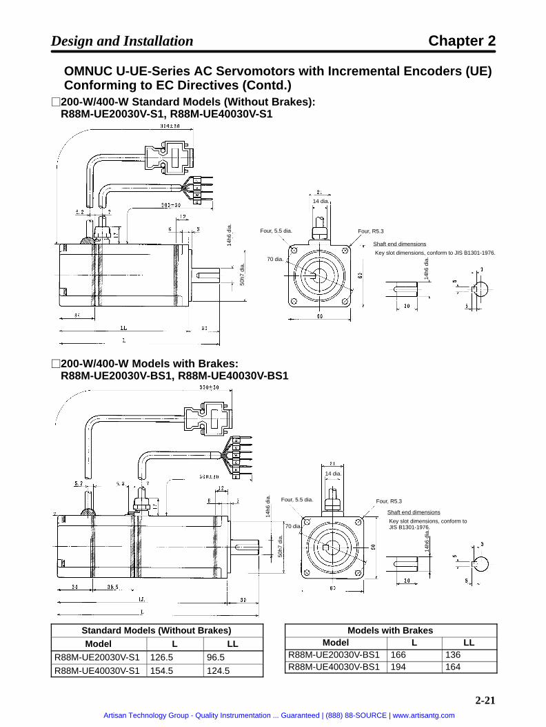
OMNUC U-UE-Series AC Servomotors with Incremental Encoders (UE)Conforming to EC Directives (Contd.)
200-W/400-W Standard Models (Without Brakes): R88M-UE20030V-S1, R88M-UE40030V-S1
Four, 5.5 dia. Four, R5.314
h6 d
ia.
50h7
dia
.
14h6
dia
.
Shaft end dimensions
Key slot dimensions, conform to JIS B1301-1976.
14 dia.
70 dia.
200-W/400-W Models with Brakes:R88M-UE20030V-BS1, R88M-UE40030V-BS1
Four, 5.5 dia. Four, R5.3
14h6
dia
.
50h7
dia
.
14h6
dia
.
Shaft end dimensions
Key slot dimensions, conform to JIS B1301-1976.
14 dia.
70 dia.
Standard Models (Without Brakes)Model L LL
R88M-UE20030V-S1 126.5 96.5
R88M-UE40030V-S1 154.5 124.5
Models with BrakesModel L LL
R88M-UE20030V-BS1 166 136R88M-UE40030V-BS1 194 164
Design and Installation Chapter 2
Artisan Technology Group - Quality Instrumentation ... Guaranteed | (888) 88-SOURCE | www.artisantg.com

2-22
OMNUC U-UE-Series AC Servomotors with Incremental Encoders (UE)Conforming to EC Directives (Contd.)
750-W Standard Models (Without Brakes): R88M-UE75030V-S1
Four, 7 dia.Four, R8.2
16h6
dia
.
70h7
dia
.
16h6
dia
.
Shaft end dimensions
Key slot dimensions, conform to JIS B1301-1976.
14 dia.
90 dia.
750-W Models with Brakes: R88M-UE75030V-BS1
Four, 7 dia.Four, R8.2
16h6
dia
.
70h7
dia
.
16h6
dia
.
Shaft end dimensions
Key slot dimensions, conform to JIS B1301-1976.
14 dia.
90 dia.
Design and Installation Chapter 2
Artisan Technology Group - Quality Instrumentation ... Guaranteed | (888) 88-SOURCE | www.artisantg.com

2-23
OMNUC U-Series AC Servomotors with Incremental Encoders (U-INC1 to 2 kW)
1.0-kW/1.5-kW/2.0-kW Standard Models (Without Brakes)Not Conforming to Any Standards: R88M-U1K030H/-U1K530H/-U2K030HConforming to EC Directives: R88M-U1K030V-S1/-U1K530V-S1/-U2K030V-S1
Four, 7 dia.
24h6
dia
.
95h7
dia
.
115 dia.
130 dia.
1.0-kW/1.5-kW/2.0-kW Models With BrakesNot Conforming to Any Standards: R88M-U1K030H-B/-U1K530H-B/-U2K030H-BConforming to EC Directives: R88M-U1K030V-BS1/-U1K530V-BS1/-U2K030V-BS1
Four, 7 dia.
24h6
dia
.
95h7
dia
.
115 dia.
130 dia.
Standard Models (Without Brakes)Model L LL
R88M-U1K030 194 149
R88M-U1K530 220 175
R88M-U2K030 243 198
Models with BrakesModel L LL
R88M-U1K030-B 238 193R88M-U1K530-B 264 219R88M-U2K030-B 287 242
Note Servomotors with model numbers ending in “S1” have straight shafts with keys. Refer to page2-25 U-Series AC Servomotor Shaft Dimensions with Keys for key dimensions.
Design and Installation Chapter 2
Artisan Technology Group - Quality Instrumentation ... Guaranteed | (888) 88-SOURCE | www.artisantg.com
2-24
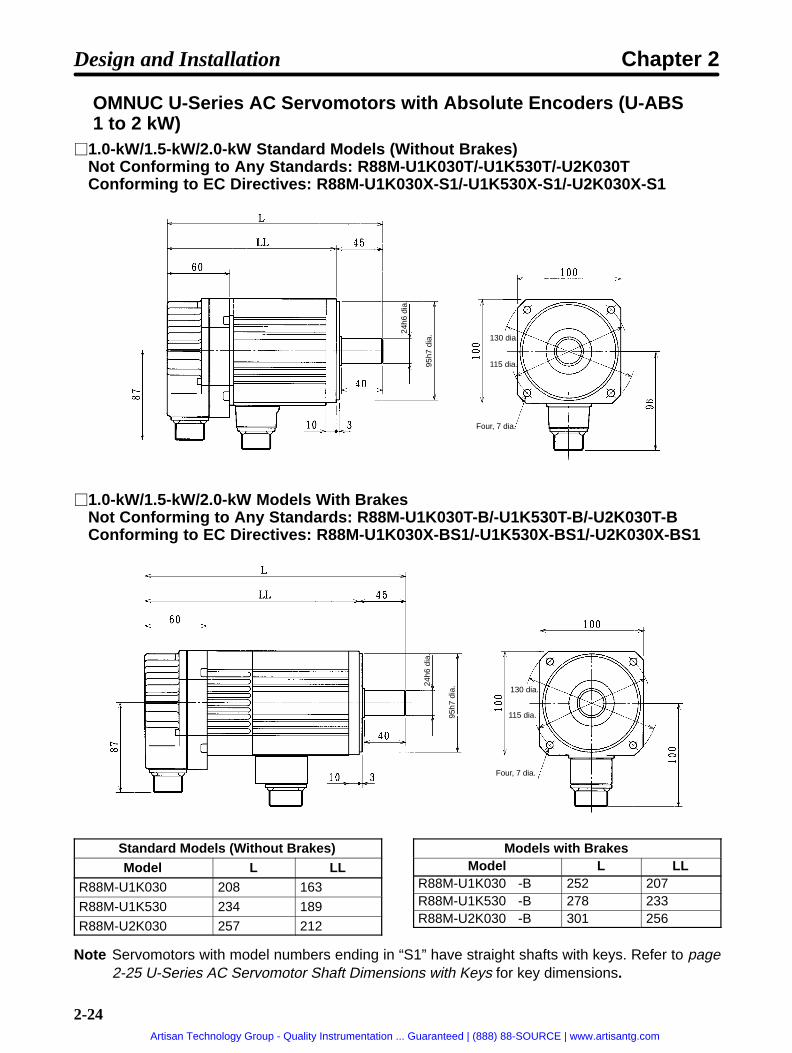
OMNUC U-Series AC Servomotors with Absolute Encoders (U-ABS1 to 2 kW)
1.0-kW/1.5-kW/2.0-kW Standard Models (Without Brakes)Not Conforming to Any Standards: R88M-U1K030T/-U1K530T/-U2K030TConforming to EC Directives: R88M-U1K030X-S1/-U1K530X-S1/-U2K030X-S1
Four, 7 dia.
24h6
dia
.
95h7
dia
.
115 dia.
130 dia.
1.0-kW/1.5-kW/2.0-kW Models With BrakesNot Conforming to Any Standards: R88M-U1K030T-B/-U1K530T-B/-U2K030T-BConforming to EC Directives: R88M-U1K030X-BS1/-U1K530X-BS1/-U2K030X-BS1
Four, 7 dia.
24h6
dia
.
95h7
dia
.
115 dia.
130 dia.
Standard Models (Without Brakes)Model L LL
R88M-U1K030 208 163
R88M-U1K530 234 189
R88M-U2K030 257 212
Models with BrakesModel L LL
R88M-U1K030-B 252 207R88M-U1K530-B 278 233R88M-U2K030-B 301 256
Note Servomotors with model numbers ending in “S1” have straight shafts with keys. Refer to page2-25 U-Series AC Servomotor Shaft Dimensions with Keys for key dimensions.
Design and Installation Chapter 2
Artisan Technology Group - Quality Instrumentation ... Guaranteed | (888) 88-SOURCE | www.artisantg.com

2-25
U-Series AC Servomotor Shaft Dimensions with Keys (U-INC, U-ABS, 1 to 2 kW)
Standard U-series AC Servomotors do not have keys on the shafts. The shaft dimensions of motorswith keys are shown below. Motors with keys are indicated by adding “-S1” to the end of the model num-ber. Key slots are based on JIS B1301-1976.
1.0-kW/1.5-kW/2.0-kW ModelsStandard: R88M-U1K030 -S1, R88M-U1K530-S1, R88M-U2K030-S1With Brakes: R88M-U1K030 -BS1, R88M-U1K530-BS1, R88M-U2K030-BS1
M8 with effectivedepth of 16
24h6
dia
.
Design and Installation Chapter 2
Artisan Technology Group - Quality Instrumentation ... Guaranteed | (888) 88-SOURCE | www.artisantg.com

2-26
OMNUC H-Series AC Servomotor with Incremental Encoder (H) 50-W/100-W Standard Models (Without Brakes): R88M-H05030, R88M-H10030 50-W/100-W Models with Brakes: R88M-H05030-B, R88M-H10030-B
63 dia.
Four, R4
Four, 5 dia.
80±0.2 dia.
93 dia. max.
500
0.025dia.
80
0.009dia.
6666±0.4
Standard Models (Without Brakes)Model L1 L2 L3
R88M-H05030 (50 W) 53.5 99 45.5
R88M-H10030 (100 W) 63.5 109 45.5
Models With BrakesModel L1 L2 L3
R88M-H05030-B (50 W) 84.5 130 45.5
R88M-H10030-B (100 W) 94.5 140 45.5
200-W/300-W Standard Models (Without Brakes): R88M-H20030, R88M-H30030 200-W/300-W Models with Brakes: R88M-H20030-B, R88M-H30030-B
Four, R10
Four, 6 dia.
90±0.2 dia.
107 dia. max.
140
0.011dia.
77 dia. 700
0.03dia.
8080±0.4
Standard Models (Without Brakes)Model L1 L2 L3
R88M-H20030 (200 W) 77 123.5 46.5
R88M-H30030 (300 W) 89 135.5 46.5
Models With BrakesModel L1 L2 L3
R88M-H20030-B (200 W) 107.5 154 46.5
R88M-H30030-B (300 W) 119.5 166 46.5
Design and Installation Chapter 2
Artisan Technology Group - Quality Instrumentation ... Guaranteed | (888) 88-SOURCE | www.artisantg.com

2-27
OMNUC H-Series AC Servomotors with Incremental Encoders (H)(Contd.)
500-W/750-W/1100-W Standard Models (Without Brakes):R88M-H50030, R88M-H75030, R88M-H1K130
500-W/750-W/1100-W Models with Brakes:R88M-H50030-B, R88M-H75030-B, R88M-H1K130-B
Four, R15
130±0.2 dia.
Four, 9 dia.
162 dia. max.
1100
0.035dia.
190
0.013dia.
160
0.011dia.
77 dia.
Shaft DimensionsR88M-H50030/-H50030-BR88M-H75030/-H75030-B
Shaft DimensionsR88M-H1K130/-H1K130-B
Standard Models (Without Brakes)Model L1 L2 L3
R88M-H50030 (500 W) 107.5 154.0 46.5
R88M-H75030 (750 W) 126.0 172.5 46.5
R88M-H1K130 (1100 W) 144.5 191.0 46.5
Models With BrakesModel L1 L2 L3
R88M-H50030-B (500 W) 148.5 195.0 46.5
R88M-H75030-B (750 W) 167.0 213.5 46.5
R88M-H1K130-B (1100 W) 185.5 232.0 46.5
Design and Installation Chapter 2
Artisan Technology Group - Quality Instrumentation ... Guaranteed | (888) 88-SOURCE | www.artisantg.com

2-28
OMNUC M-Series AC Servomotors with Resolvers (M) 60-W/120-W (4,000 r/min) Standard Models (Without Brakes): R88M-M06040,
R88M-M12040
Four, 5 dia.
… 50
h7 d
ia.
8h6
dia.
7.4 dia.
60-W/120-W (4,000 r/min) Models with Brakes: R88M-M06040-B, R88M-M12040-B
Four, 5 dia.
°
°
8h6
dia.
50h7
dia
.
7.4 dia.
Standard Models (Without Brakes)Model L LL LM
R88M-M06040 150 120 85
R88M-M12040 175 145 110
Models with BrakesModel LX LY LM
R88M-M06040-B 184 154 85
R88M-M12040-B 209 179 110
Shaft End Dimensions
Design and Installation Chapter 2
Artisan Technology Group - Quality Instrumentation ... Guaranteed | (888) 88-SOURCE | www.artisantg.com

2-29
OMNUC M-Series AC Servomotors with Resolvers (M) (Contd.) 200-W (2,000 r/min) Standard Models (Without Brakes): R88M-M20020 200-W/400-W (4,000 r/min) Standard Models: R88M-M20040, R88M-40040
80h7
dia
.14h6
dia
.Four, 7dia.
7.4 dia.
100±0.2 dia
200-W (2,000 r/min) Models with Brakes: R88M-M20020-B 200-W/400-W (4,000 r/min) Models with Brakes: R88M-M20040-B, R88M-M40040-B
80h7
dia
.
14h6
dia
.
Four, 7dia.
7.4 dia.
100±0.2 dia
Standard Models (Without Brakes)Model L LL LM
R88M-M20040 166 131 92
R88M-M20020 196 161 122
R88M-M40040
Models with BrakesModel LX LY LM
R88M-M20040-B 196 161 92
R88M-M20020-B 226 191 122
R88M-M40040-B
Shaft End Dimensions
Design and Installation Chapter 2
Artisan Technology Group - Quality Instrumentation ... Guaranteed | (888) 88-SOURCE | www.artisantg.com

2-30
OMNUC M-Series AC Servomotors with Resolvers (M) (Contd.)
200-W/400-W/700-W (1,200 r/min) Standard Models (Without Brakes): R88M-M20012, R88M-M40012, R88M-M70012
400-W/700-W/1,100-W (2,000 r/min) Standard Models (Without Brakes):R88M-M40020, R88M-M70020, R88M-M1K120
700-W/1,100-W/2,000-W (4,000 r/min) Standard Models (Without Brakes):R88M-70040, R88M-M1K140, R88M-M2K040
Four, 9 dia.
145±0.2 dia.
110h
7 di
a.19h6
dia
.
200-W/400-W/700-W (1,200 r/min) Models with Brakes: R88M-M20012-B, R88M-M40012-B, R88M-M70012-B
400-W/700-W/1,100-W (2,000 r/min) Models with Brakes: R88M-M40020-B,R88M-M70020-B, R88M-M1K120B
700-W/1,100-W/2,000-W (4,000 r/min) Models with Brakes: R88M-M70040-B,R88M-M1K140-B, R88M-M2K040-B
110h
7 di
a.19h6
dia
.
145±0.2 dia.
Four, 9 dia.
165 dia.
Design and Installation Chapter 2
Artisan Technology Group - Quality Instrumentation ... Guaranteed | (888) 88-SOURCE | www.artisantg.com

2-31
Standard Models
Model L LL LM
R88M-M20012 240 195 156
R88M-M40020R88M-M70040
R88M-M40012 275 230 191
R88M-M70020R88M-M1K140
R88M-M70012 345 300 261
R88M-M1K120
R88M-M2K040
Models with Brakes
Model LX LY LM
R88M-M20012-B 282 237 156
R88M-M40020-BR88M-M70040-B
R88M-M40012-B 317 272 191
R88M-M70020-BR88M-M1K140-B
R88M-M70012-B 387 342 261
R88M-M1K120-B
R88M-M2K040-B
Shaft End Directions
OMNUC M-Series AC Servomotors with Resolvers (Contd.) 1,100-W/1,400-W/1,800-W (1,200 r/min) Standard Models:
R88M-M1K112/-M1K412/-M1K812
1,800-W/2,200-W (2,000 r/min) Standard Models: R88M-M1K820/-M2K220
114.
3h735
dia.
200±0.3 dia.
Four, 14 dia.
230 dia.
+0.
01
0
180
x 18
0
Design and Installation Chapter 2
Artisan Technology Group - Quality Instrumentation ... Guaranteed | (888) 88-SOURCE | www.artisantg.com

2-32
1,100-W/1,400-W/1,800-W (1,200 r/min) Models with Brakes: R88M-M1K112-B/-M1K412-B/-M1K812-B
1,800-W/2,200-W (2,000 r/min) Models with Brakes: R88M-M1K820-B/-M2K220-B
114.
3h7
200±0.3 dia.
Four, 14 dia.
230 dia.
35
di
a.+
0.01
0
180
x 18
0
Standard ModelsModel L LL LM LX LY LZ
R88M-M1K112 370 291 252 439 360 256
R88M-M1K820
R88M-M1K412 400 321 282 469 390 286
R88M-M2K220R88M-M1K812 460 381 342 529 450 346
Models with Brakes
Model L LL LM LX LY LZ
R88M-M1K112-B 370 291 252 439 360 256
R88M-M1K820-B
R88M-M1K412-B 400 321 282 469 390 286
R88M-M2K220-B
R88M-M1K812-B 460 381 342 529 450 346
Shaft End Directions
10h9
C1
R560 8
4.5
Design and Installation Chapter 2
Artisan Technology Group - Quality Instrumentation ... Guaranteed | (888) 88-SOURCE | www.artisantg.com

2-33
2-1-2 Installation Conditions
Position Driver
Space Around Drivers• Install Position Drivers according to the dimensions shown in the following illustration to ensure prop-
er heat dispersion and convection inside the panel. Also install a fan for circulation if Position Driversare installed side by side to prevent uneven temperatures from developing inside the panel.
• Mount the Position Drivers vertically (so that the model number and writing can be read).
ÉÉÉÉÉÉÉÉÉÉÉÉÉÉÉÉÉÉÉÉÉÉÉÉÉÉÉÉÉÉÉÉÉÉÉÉÉÉÉÉÉÉÉÉÉÉÉÉÉÉÉÉÉÉÉÉÉÉÉÉÉÉÉÉÉÉÉÉÉÉÉÉÉÉÉÉÉÉÉÉÉÉÉÉÉÉÉÉÉÉÉÉÉÉÉÉÉÉÉÉÉÉÉÉÉÉÉÉÉÉÉÉÉÉÉÉÉÉÉÉÉÉÉÉÉÉÉÉÉÉÉÉÉÉÉÉÉÉÉÉÉÉÉÉÉÉÉÉÉÉÉÉÉÉÉÉÉÉÉÉÉÉÉÉÉÉÉÉÉÉÉÉÉÉÉÉÉÉÉÉÉÉÉÉÉÉÉÉÉÉÉÉÉÉÉÉÉÉÉÉÉÉÉÉÉÉÉÉÉÉÉÉÉÉÉÉÉÉÉÉÉÉÉÉÉÉÉÉÉÉÉÉÉÉÉÉÉÉÉÉÉÉÉÉÉÉÉÉÉÉÉÉÉÉÉÉÉÉÉÉÉÉÉÉÉÉÉÉÉÉÉÉÉÉÉÉÉÉÉÉÉÉÉÉÉÉ
50 mm min.
50 mm min.W W
30 mm min.
Fan Fan
Pos
ition
Driv
er
W = 10 mm min.
Side of Driver
Pos
ition
Driv
er
Pos
ition
Driv
er
Operating EnvironmentBe sure that the environment in which Position Drivers are operated meets the following conditions.
• Ambient operating temperature: 0°C to +55°C• Ambient operating humidity: 35% to 90% (RH, with no condensation)
• Atmosphere: No corrosive gases.
Ambient Temperature• Position Drivers should be operated in environments in which there is minimal temperature rise to
maintain a high level of reliability.
• Temperature rise in any Position Driver installed in a closed space, such as a control box, will causethe ambient temperature to rise inside the entire closed space. Use a fan or a air conditioner to pre-vent the ambient temperature of the Position Driver from exceeding 55°C.
• Position Driver surface temperatures may rise to as much as 40°C above the ambient temperature.Use heat-resistant materials for wiring, and keep separate any devices or wiring that are sensitive toheat.
• The service life of a Position Driver is largely determined by the temperature around the internal elec-trolytic capacitors. The service life of an electrolytic capacitor is affected by a drop in electrolytic vol-ume and an increase in internal resistance, which can result in overvoltage alarms, malfunctioningdue to noise, and damage to individual elements. If a Position Driver is always operated at the maxi-mum ambient temperature of 35°C, then a service life of approximately 50,000 hours can be ex-pected. A drop of 10°C in the ambient temperature will approximately double the expected servicelife.
Design and Installation Chapter 2
Artisan Technology Group - Quality Instrumentation ... Guaranteed | (888) 88-SOURCE | www.artisantg.com

2-34
Keeping Foreign Objects Out of Units• Place a cover over the Units or take other preventative measures to prevent foreign objects, such as
drill filings, from getting into the Position Driver during installation. Be sure to remove the cover afterinstallation is complete. If the cover is left on during operation, heat buildup may damage the Driver.
• Take measures during installation and operation to prevent foreign objects such as metal particles,oil, machining oil, dust, or water from getting inside of the Position Driver.
AC Servomotors
Operating EnvironmentBe sure that the environment in which the Servomotor is operated meets the following conditions.
• Ambient operating temperature: 0°C to +40°C• Ambient operating humidity: OMNUC U Series: 20% to 80% (RH, with no condensation)
OMNUC U-UE Series: 20% to 80% (RH, with no condensation)OMNUC H Series: 35% to 85% (RH, with no condensation)OMNUC M Series: 35% to 85% (RH, with no condensation)
• Atmosphere: No corrosive gases.
Impact and Load• The Servomotor is resistant to impacts of up to
98 m/s2 10 G. Do not subject it to heavy impacts orloads during transport, installation, or positioning. Inaddition, do not hold onto the encoder/resolverarea, cable, or connector areas when transporting it.
• Always use a pulley remover to remove pulleys,couplings, or other objects from the shaft.
• Secure cables so that there is no impact or load placed on the cable connector areas.
Connecting to Mechanical Systems• The axial loads for Servomotors are specified in sec-
tion 5-2 Servomotor Specifications. If an axial loadgreater than that specified is applied to a Servomo-tor, it will reduce the service life of the motor bearingsand may damage the motor shaft. When connectingto a load, use couplings that can sufficiently absorbmechanical eccentricity and variation.
Recommended Coupling
Name MakerOldham coupling Myghty Co., Ltd
• For spur gears, an extremely large radial load maybe applied depending on the gear precision. Usespur gears with a high degree of accuracy (for exam-ple, JIS class 2: normal line pitch error of 6 µm max.for a pitch circle diameter of 50 mm). If the gear preci-sion is not adequate, allow backlash to ensure thatno radial load is placed on the motor shaft.
Ball screw center line
Motor shaft center line Shaft coredisplacement
Backlash
Adjust backlashby adjusting thedistance betweenshafts.
Design and Installation Chapter 2
Artisan Technology Group - Quality Instrumentation ... Guaranteed | (888) 88-SOURCE | www.artisantg.com

2-35
• Bevel gears will cause a load to be applied in thethrust direction depending on the structural preci-sion, the gear precision, and temperature changes.Provide appropriate backlash or take other mea-sures to ensure that no thrust load is applied whichexceeds specifications.
• Do not put rubber packing on the flange surface. Ifthe flange is mounted with rubber packing, the motorflange may separate due to the tightening strength.
• When connecting to a V-belt or timing belt, consult the maker for belt selection and tension. A radialload twice the belt tension will be placed on the motor shaft. Do not allow a radial load exceedingspecifications to be placed on the motor shaft due to belt tension. If an excessive radial load is ap-plied, the motor shaft may be damaged. Set up the structure so that the radial load can be adjusted. Alarge radial load may also be applied as a result of belt vibration. Attach a brace and adjust PositionDriver gain so that belt vibration is minimized.
Tension Motor shaft
Make adjustable.
Load shaft
Pulley
Belt
Water and Drip Resistance• The Servomotor does not have a water-proof structure. Except for the connector areas, the protec-
tive structure meets the following JEM (The Japan Electrical Manufacturers’ Association) standards:U Series, 30 to 750 W Conforming to UL/cUL and UE Type Not Conforming to Any Standards: IP-42 U Series, 30 to 750 W Conforming to EC Directives and UE Type Conforming to EC Directives: IP-44(except shaft penetration point)U Series, 1 to 2 kW Not Conforming to Any Standards: IP-65 (except shaft penetration point)U Series, 1 to 2 kW Conforming to EC Directives: IP-55 (including shaft penetration point)H Series: IP-52M Series: IP-42
Note Protective Structure: Indicated as IP-(IP: Protection rating symbol, : rating class) ac-cording to the IEC standard (IEC529: 1989-11).
• If the Servomotor is used in an environment in which condensation occurs, water may enter inside ofthe encoder/resolver from the end surfaces of cables due to motor temperature changes. Either takemeasures to ensure that water cannot penetrate in this way, or use water-proof connectors. Evenwhen machinery is not in use, water penetration can be avoided by taking measures, such as keep-ing the motor in servo-lock status, to minimize temperature changes.
• If machining oil with surfactants (e.g., coolant fluids) or their spray penetrate inside of the motor, in-sulation defects or short-circuiting may occur. Take measures to prevent machining oil penetration.
• The water and drip resistance of the standard cables for U-Series Servomotors of 1 to 2 kW is equiv-alent to IP-30. Use water-resistance cables for the power cables and encoder cables in locationssubject to contact with water. Use the following recommended products for power cable and encodercable connectors when the device is to meet EC directives.
Make moveable.
Bevel gear
Design and Installation Chapter 2
Artisan Technology Group - Quality Instrumentation ... Guaranteed | (888) 88-SOURCE | www.artisantg.com
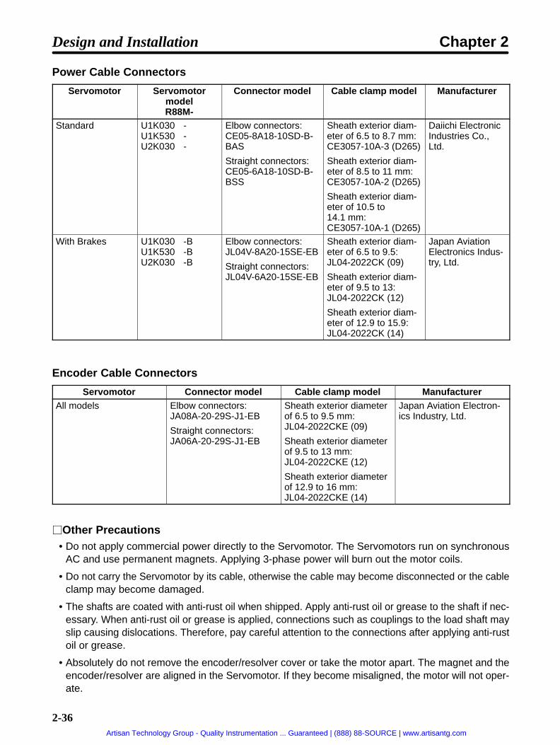
2-36
Power Cable Connectors
Servomotor ServomotormodelR88M-
Connector model Cable clamp model Manufacturer
Standard U1K030-U1K530-U2K030-
Elbow connectors:CE05-8A18-10SD-B-BAS
Straight connectors:CE05-6A18-10SD-B-BSS
Sheath exterior diam-eter of 6.5 to 8.7 mm:CE3057-10A-3 (D265)
Sheath exterior diam-eter of 8.5 to 11 mm:CE3057-10A-2 (D265)
Sheath exterior diam-eter of 10.5 to14.1 mm:CE3057-10A-1 (D265)
Daiichi ElectronicIndustries Co.,Ltd.
With Brakes U1K030-BU1K530-BU2K030-B
Elbow connectors:JL04V-8A20-15SE-EB
Straight connectors:JL04V-6A20-15SE-EB
Sheath exterior diam-eter of 6.5 to 9.5:JL04-2022CK (09)
Sheath exterior diam-eter of 9.5 to 13:JL04-2022CK (12)
Sheath exterior diam-eter of 12.9 to 15.9:JL04-2022CK (14)
Japan AviationElectronics Indus-try, Ltd.
Encoder Cable Connectors
Servomotor Connector model Cable clamp model ManufacturerAll models Elbow connectors:
JA08A-20-29S-J1-EB
Straight connectors:JA06A-20-29S-J1-EB
Sheath exterior diameterof 6.5 to 9.5 mm: JL04-2022CKE (09)
Sheath exterior diameterof 9.5 to 13 mm: JL04-2022CKE (12)
Sheath exterior diameterof 12.9 to 16 mm: JL04-2022CKE (14)
Japan Aviation Electron-ics Industry, Ltd.
Other Precautions• Do not apply commercial power directly to the Servomotor. The Servomotors run on synchronous
AC and use permanent magnets. Applying 3-phase power will burn out the motor coils.
• Do not carry the Servomotor by its cable, otherwise the cable may become disconnected or the cableclamp may become damaged.
• The shafts are coated with anti-rust oil when shipped. Apply anti-rust oil or grease to the shaft if nec-essary. When anti-rust oil or grease is applied, connections such as couplings to the load shaft mayslip causing dislocations. Therefore, pay careful attention to the connections after applying anti-rustoil or grease.
• Absolutely do not remove the encoder/resolver cover or take the motor apart. The magnet and theencoder/resolver are aligned in the Servomotor. If they become misaligned, the motor will not oper-ate.
Design and Installation Chapter 2
Artisan Technology Group - Quality Instrumentation ... Guaranteed | (888) 88-SOURCE | www.artisantg.com

2-37
• The Servomotor may not produce sufficient torque when moved only a small distance from the pointwhere power is turned ON (a distance equivalent to about ±6 pulses). If only a very small distance isto be moved, move the motor at least ±6 pulses after turning ON the power before starting actualoperation.
Design and Installation Chapter 2
Artisan Technology Group - Quality Instrumentation ... Guaranteed | (888) 88-SOURCE | www.artisantg.com
2-38
2-2 Wiring
2-2-1 OverviewUse a general-purpose control cable (purchased separately) to connect the Position Driver to the Pro-grammable Controller. For connecting the Position Driver to an AC Servomotor, use a dedicated Encod-er/Resolver Cable and a Power Cable. (For the M Series there is no dedicated power cable. It must beprepared by the user.)
Note Refer to Chapter 5 Specifications for details on connectors and cables.
Design and Installation Chapter 2
Artisan Technology Group - Quality Instrumentation ... Guaranteed | (888) 88-SOURCE | www.artisantg.com

2-39
Using OMNUC U-series AC Servomotors: 30 to 750 W Conforming toUL/cUL or UE Type Not Conforming to Any Standards
SYSMAC CV/C-seriesProgrammable Controller
General-purposeControl CableFND-CCXS
Power CableR88A-CAUSR88A-CAUB
OMNUC U-Series AC ServomotorConforming to UL/cUL or U-UE-Series AC Servomotor NotConforming to Any Standards
Encoder CableR88A-CRUC (for incremental encoder)R88A-CSUC (for absolute encoder)
C200HX/HG/HE or CQM1Programmable Controller
SRM1-C01/-C02Master Control Unit
CompoBus/S Communications Cable(SCA1-4F10 Flat Cable or commer-cially available VCTF cable)
FND-X-series Position Driver(DIO Type)
FND-X-series Position Driver(CompoBus/S Type)
Backup Battery
Connect when using aServomotor with an abso-lute encoder.
Note Refer to Chapter 5 Specifications for connector and cable specifications.
Design and Installation Chapter 2
Artisan Technology Group - Quality Instrumentation ... Guaranteed | (888) 88-SOURCE | www.artisantg.com

2-40
Using OMNUC U-series AC Servomotors: 30 to 750 W Conforming toEC Directives or UE Type Conforming to EC Directives
SYSMAC CV/C-seriesProgrammable Controller
Power CableR88A-CAU001R88A-CAU01B
OMNUC U-Series AC ServomotorConforming to EC Directives or U-UE-Series AC Servomotor Con-forming to EC Directives
Encoder CableR88A-CRUDC (for incremental encoder)R88A-CSUDC (for absolute encoder)
C200HX/HG/HE or CQM1Programmable Controller
SRM1-C01/-C02Master Control Unit
FND-X-series Position Driver(DIO Type)
FND-X-series Position Driver(CompoBus/S Type)
Backup Battery
Connect when using aServomotor with an abso-lute encoder.
CompoBus/S Communications Cable(SCA1-4F10 Flat Cable or commer-cially available VCTF cable)
General-purposeControl CableFND-CCXS
Note Refer to Chapter 5 Specifications for connector and cable specifications.
Design and Installation Chapter 2
Artisan Technology Group - Quality Instrumentation ... Guaranteed | (888) 88-SOURCE | www.artisantg.com

2-41
Using OMNUC U-series AC Servomotors: 1 to 2 kW
SYSMAC CV/C-seriesProgrammable Controller
General-purposeControl CableFND-CCXS
Power CableR88A-CAUBNR88A-CAUBB
OMNUC U-series ACServomotor: 1 to 2 kW
Encoder CableR88A-CRUBN (for incremental encoder/absolute encoder)
C200HX/HG/HE or CQM1Programmable Controller
SRM1-C01/-C02Master Control Unit
FND-X-series Position Driver(DIO Type)
FND-X-series Position Driver(CompoBus/S Type)
Backup Battery
CompoBus/S CommunicationsCable (SCA1-4F10 Flat Cableor commercially available VCTFcable)
Connect when using aServomotor with an abso-lute encoder.
Note 1. Refer to Chapter 5 Specifications for connector and cable specifications.
Note 2. To perform mounting in accordance with EC Directives, use a Servomotor that conforms toEC Directives. In addition, replace the connectors for the power cable and the encoder cableat the Servomotor with the recommended Connectors listed under Water and Drip Resist-ance in 2-1-2 Installation Conditions.
Design and Installation Chapter 2
Artisan Technology Group - Quality Instrumentation ... Guaranteed | (888) 88-SOURCE | www.artisantg.com

2-42
Using an OMNUC H-series AC Servomotor
SYSMAC CV/C-seriesProgrammable Controller
General-purposeControl CableFND-CCXS
FND-X-series Position Driver(DIO Type)
Power CableR88A-CAHSR88A-CAHB
OMNUC H-series ACServomotor
Conversion CableR88A-CRH0R5T
SYSMAC HX/HG/HE or CQM1Programmable Controller
SRM1-C01/-C02Master Control Unit
FND-X-series Position Driver(CompoBus/S Type)
Encoder CableR88A-CRHC
CompoBus/S Communications Cable(SCA1-4F10 Flat Cable or commer-cially available VCTF cable)
Note Refer to Chapter 5 Specifications for connector and cable specifications.
Design and Installation Chapter 2
Artisan Technology Group - Quality Instrumentation ... Guaranteed | (888) 88-SOURCE | www.artisantg.com

2-43
Using an OMNUC M-series AC Servomotor
General-purposeControl CableFND-CCXS
FND-X-seriesPosition Driver(DIO Type)
SYSMAC CV/C-seriesProgrammable Controller
C200HX/HG/HE or CQM1Programmable Controller
SRM1-C01/-C02Master Control Unit
FND-X-series PositionDriver (CompoBus/S Type)
Power Cable(Prepared by user.)
Conversion CableR88A-CRM0R5T
OMNUC M-seriesAC Servomotor
Resolver CableR88A-CRMN
CompoBus/S Communications Cable(SCA1-4F10 Flat Cable or commer-cially available VCTF cable)
Note Refer to Chapter 5 Specifications for connector and cable specifications.
Design and Installation Chapter 2
Artisan Technology Group - Quality Instrumentation ... Guaranteed | (888) 88-SOURCE | www.artisantg.com
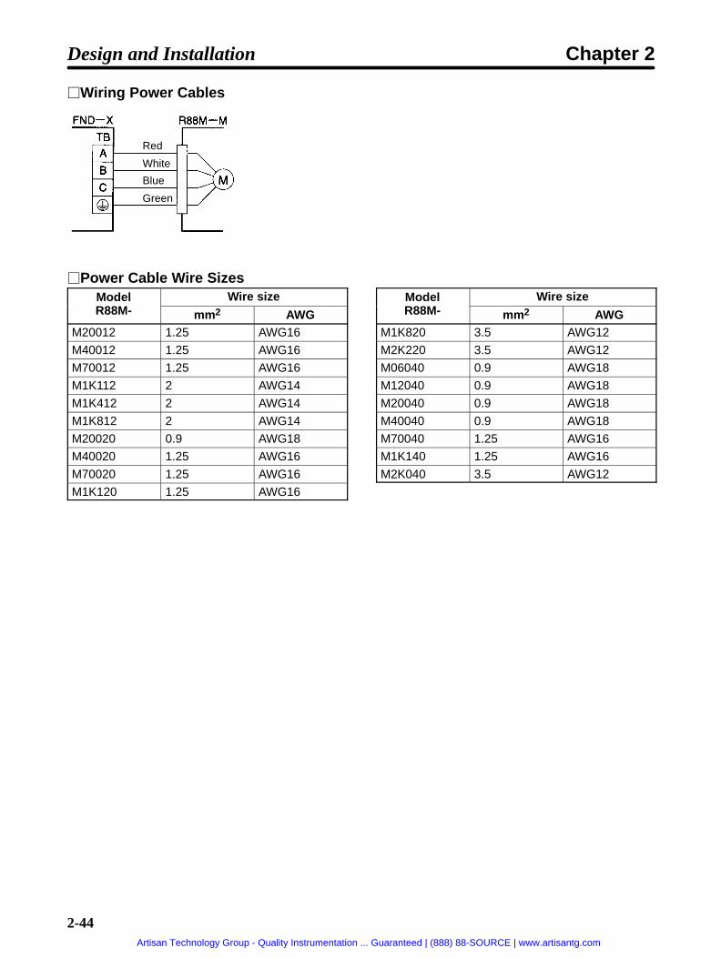
2-44
Wiring Power Cables
Red
White
Blue
Green
Power Cable Wire SizesModelR88M
Wire sizeR88M- mm2 AWG
M20012 1.25 AWG16
M40012 1.25 AWG16
M70012 1.25 AWG16
M1K112 2 AWG14
M1K412 2 AWG14
M1K812 2 AWG14
M20020 0.9 AWG18
M40020 1.25 AWG16
M70020 1.25 AWG16
M1K120 1.25 AWG16
ModelR88M
Wire sizeR88M- mm2 AWG
M1K820 3.5 AWG12
M2K220 3.5 AWG12
M06040 0.9 AWG18
M12040 0.9 AWG18
M20040 0.9 AWG18
M40040 0.9 AWG18
M70040 1.25 AWG16
M1K140 1.25 AWG16
M2K040 3.5 AWG12
Design and Installation Chapter 2
Artisan Technology Group - Quality Instrumentation ... Guaranteed | (888) 88-SOURCE | www.artisantg.com

2-45
2-2-2 Control Circuitry Terminal Wiring
DIO Position Drivers
Control Signal Connector (CN1: CONT) Pin Arrangement
2 CWL
4 RUN
8
10 TEACH
1 CCWL
3 ORG
7 SEARCH
9
20
22 READY
24 ORGSTP
19 OGND
21
25 T.COM
23 S.COM
6 RESET
5 START
26 RUNON
28 ALM
27 INP
CW limit in-put
RUNcommand
Alarm reset
Originproximity
Start
CCW limitinput
Origin search
Ready
Originstop
Motorrunning
Alarm
Originsearchcompleted
Teachingcompleted
Positioningcompleted
+JOG
–JOG
STOP
BO
+JOGoperation
Decelerationstop
Brakeoutput
12 P.IN1
14 P.IN3
18
16 P.IN5
Pointselection 1/Position 1
P.IN7 Position 7
11 P.IN0
13 P.IN2
17 P.IN6
15 P.IN4
Teach
30
32 P.OUT3
34 P.OUT5
36 +24V
Point output5
+24-VDCpower sup-ply input forcontrol
P.OUT1Point output1/ Positionselection 2
Outputground
29 P.OUT0
31
35 P.OUT6
33 P.OUT4
P.OUT2Pointselection 3/Position 3
Pointselection 5/Position 5
Pointselection 0/Position 0
Pointselection 2/Position 2
Pointselection 4/Position 4
Pointselection 6/Position 6
–JOGoperation
Point output3/ Positionselection 4
Point output0/ Positionselection 1
Point output2/ Positionselection 3
Point output4/ Speedselection
Point output6
Connectors UsedSumitomo 3M Receptacle at Position Driver 10236-6202JL
Soldered plug at cable side 10136-3000VECase at cable side 10336-52A0-008
CompoBus/S Position Drivers
CompoBus/S Communications Terminal Block (CN1: CONT) PinArrangement
Signal Name FunctionsBD H CompoBus/S serial line (+) These are the terminals for connecting
CompoBus/S communications cables BeBD L CompoBus/S serial line (–)
CompoBus/S communications cables. Becareful to connect the polarities correctly.
I/O AllocationThe FND-X has 16 input points and 16 output points.
Design and Installation Chapter 2
Artisan Technology Group - Quality Instrumentation ... Guaranteed | (888) 88-SOURCE | www.artisantg.com

2-46
IN (16 Input Points)
I/O allocation Signal NameOUT0 RUN RUN command
OUT1 START START
OUT2 RESET Alarm reset
OUT3 SEARCH Origin search
OUT4 +JOG +JOG operation
OUT5 –JOG –JOG operation
OUT6 TEACH Teach
OUT7 STOP (see note 2) Deceleration stop
OUT8 P. IN0 Point selection 0/Position 0
OUT9 P. IN1 Point selection 1/Position 1
OUT10 P. IN2 Point selection 2/Position 2
OUT11 P. IN3 Point selection 3/Position 3
OUT12 P. IN4 Point selection 4/Position 4
OUT13 P. IN5 Point selection 5/Position 5
OUT14 P. IN6 Point selection 6/Position 6
OUT15 P. IN7 Position 7
OUT (16 Output Points)
I/O allocation Signal NameIN0 BO Brake output
IN1 READY READY
IN2 S.COM Origin search completed
IN3 ORGSTP Origin stop
IN4 T.COM Teaching completed
IN5 RUNON Motor running
IN6 INP Positioning completed
IN7 ALM Alarm
IN8 P. OUT0 Point output 0/Position selection 1
IN9 P. OUT1 Point output 1/Position selection 2
IN10 P. OUT2 Point output 2/Position selection 3
IN11 P. OUT3 Point output 3/Position selection 4
IN12 P. OUT4 Point output 4/Speed selection
IN13 P. OUT5 Point output 5
IN14 P. OUT6 Point output 6
IN15 --- Not used
Note 1. The I/O allocation indicates the word allocation for the Master Unit.
Note 2. The Servomotor cannot be driven if the deceleration stop signal is OFF for the external controlinput (CN4-4) or the CompoBus/S input (OUT7).
Design and Installation Chapter 2
Artisan Technology Group - Quality Instrumentation ... Guaranteed | (888) 88-SOURCE | www.artisantg.com
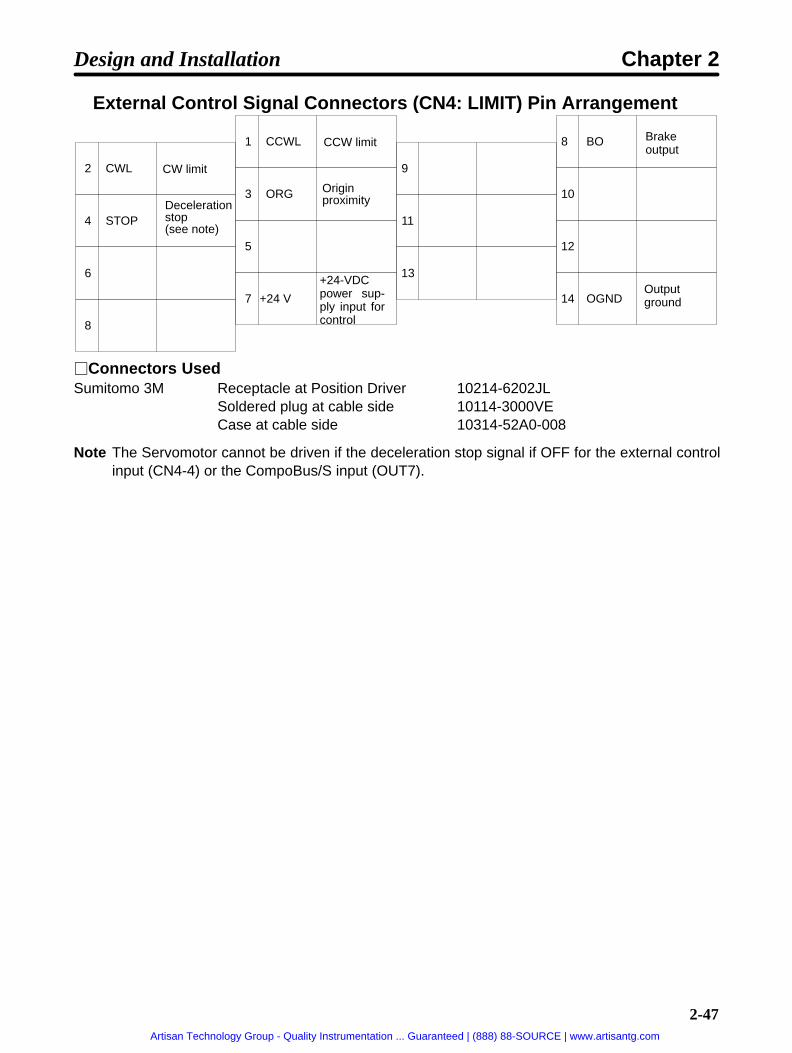
2-47
External Control Signal Connectors (CN4: LIMIT) Pin Arrangement
2 CWL
4 STOP
8
1 CCWL
3 ORG
7 +24 V
9
11
13
8 BO
10
14 OGND
12
6
5
CW limit
Decelerationstop (see note)
Originproximity
CCW limit
Outputground
+24-VDCpower sup-ply input forcontrol
Brakeoutput
Connectors UsedSumitomo 3M Receptacle at Position Driver 10214-6202JL
Soldered plug at cable side 10114-3000VECase at cable side 10314-52A0-008
Note The Servomotor cannot be driven if the deceleration stop signal if OFF for the external controlinput (CN4-4) or the CompoBus/S input (OUT7).
Design and Installation Chapter 2
Artisan Technology Group - Quality Instrumentation ... Guaranteed | (888) 88-SOURCE | www.artisantg.com

2-48
Control I/O SpecificationsDIO Compo
Bus/SSignal Name Function and interface Internal
allocationCN1-1 CN4-1 CCWL CCW limit input Inputs the + direction limit signal (sta-
tus enabled)ON: Drive possible
OFF: Motor stopped by limitdetection when driving in the + direc-tion.
IN15
CN1-2 CN4-2 CWL CW limit input Inputs the – direction limit signal (sta-tus enabled)ON: Drive possibleOFF: Motor stopped by limit detectionwhen driving in – direction.
IN16
CN1-3 CN4-3 ORG Origin proximity Signal for mechanical origin setting IN17
CN1-4 OUT0 RUN RUN command Command for beginning power on tomotor (status enabled)When OFF, error counter is cleared.ON: Power ON to motorOFF: Power OFF to motor
IN0
CN1-5 OUT1 START START Begins positioning operation (risingedge enabled)ON: START
IN1
CN1-6 OUT2 RESET Alarm reset Alarm reset signal (rising edge en-abled)
IN2
CN1-7 OUT3 SEARCH Origin search When RUN is ON (rising edge en-abled):ON: Origin search begins
When RUN is OFF (status enabled):ON: Origin teaching awaited
IN3
CN1-8 OUT4 +JOG +JOG operation +JOG operation (status enabled) ON:Rotate
IN4
CN1-9 OUT5 –JOG –JOG operation –JOG operation (status enabled) ON:Rotate
IN5
CN1-10 OUT6 TEACH Teach When ORIGIN SEARCH is OFF (sta-tus enabled):When UP-01 = 11 or 12, motor’s pres-ent position is taken for PTP datawhen this bit turns ON.When UP-01 = 13 or 14, P.IN0 toP.IN7 is taken as positioning datawhen this bit turns ON.
When RUN is OFF and ORIGINSEARCH is ON (status enabled):Motor’s present position is taken fororigin compensation amount.
IN6
Design and Installation Chapter 2
Artisan Technology Group - Quality Instrumentation ... Guaranteed | (888) 88-SOURCE | www.artisantg.com

2-49
DIO Internalallocation
Function and interfaceNameSignalCompoBus/S
CN1-11 OUT8 P.IN0 Point selection 0/Position 0
Positioning data inputs (status en-abled)
IN7
CN1-12 OUT9 P.IN1 Point selection 1/Position 1
abled)When UP-01 = 11 or 12, PTP data No.is input as positioning data. Range: 1to 64 BCD input
IN8
CN1-13 OUT10 P.IN2 Point selection 2/Position 2
to 64, BCD input.
When UP-01 = 13 or 14, positioningd t i i t R 1 t 99 BCD i
IN9
CN1-14 OUT11 P.IN3 Point selection 3/Position 3
, gdata is input. Range: 1 to 99, BCD in-put.
IN10
CN1-15 OUT12 P.IN4 Point selection 4/Position 4
Taken in order, two digits at a time,from the rightmost digits.
IN11
CN1-16 OUT13 P.IN5 Point selection 5/Position 5
IN12
CN1-17 OUT14 P.IN6 Point selection 6/Position 6
IN13
CN1-18 OUT15 P.IN7 Position 7 IN14CN1-20 CN4-4
OUT7STOP Deceleration stop Stops according to deceleration stop
mode (falling edge enabled)ON: Motor drivenOFF: Motor stopped
IN18
CN1-36 CN4-7 +24V +24-VDC powersupply input forcontrol
Power supply input terminal for controlinput.
---
CN1-19 CN4-14 OGND Output groundcommon
Output ground common for control in-put.
---
CN1-21 CN4-8IN0
BO Brake output External brake timing signal output.Output OFF when brake is operating.
OUT14
CN1-22 IN1 READY Ready Outputs ready status for receivingORIGIN SEARCH, START, TEACH, orpoint selection signal input. Outputturns ON when positioning data is re-ceived or when motor rotation is com-pleted.
OUT0
CN1-23 IN2 S.COM Origin searchcompleted
Output turns ON when motor’s presentposition is established.
OUT1
CN1-24 IN3 ORGSTP Origin stop Output turns ON when positioning isstopped at mechanical origin position.
OUT2
CN1-25 IN4 T.COM Teaching com-pleted
Output turns ON when teaching inputprocessing is completed.
OUT3
CN1-26 IN5 RUNON Motor running Output turns ON when power is turnedON to the motor.
OUT4
CN1-27 IN6 INP Positioning com-pleted
Output turns ON when error counterresidual pulses are within the UP-07(positioning completed range) setting.
OUT5
CN1-28 IN7 ALM Alarm Output indicates error occurrence atthe driver or motor. Output OFF whenan alarm occurs.
OUT6
Design and Installation Chapter 2
Artisan Technology Group - Quality Instrumentation ... Guaranteed | (888) 88-SOURCE | www.artisantg.com

2-50
DIO Internalallocation
Function and interfaceNameSignalCompoBus/S
CN1-29 IN8 P.OUT0 Point output 0/Position selection1
When UP-01 = 11 or 12:Outputs (BCD) point No. during wait-ing or execution.
OUT7
CN1-30 IN9 P.OUT1 Point output 1/Position selection2
g
When UP-01 = 13 or 14:Outputs request signal for receivingpositioning data (position and speed).
OUT8
CN1-31 IN10 P.OUT2 Point output 2/Position selection3
ositioning data ( osition and s eed).
The output ON time is set for PP-26(selection signal output time).
OUT9
CN1-32 IN11 P.OUT3 Point output 3/Position selection4
OUT10
CN1-33 IN12 P.OUT4 Point output 4/Speed selection
OUT11
CN1-34 IN13 P.OUT5 Point output 5 OUT12
CN1-35 IN14 P.OUT6 Point output 6 OUT13
Note The “internal allocations” are the numbers allocated in the CPU Unit.
Design and Installation Chapter 2
Artisan Technology Group - Quality Instrumentation ... Guaranteed | (888) 88-SOURCE | www.artisantg.com

2-51
Control Input DetailsDIO CN1-1 CompoBus/S CN4-1CCWL CCW limit N.C. condition
• Pin No. 1 is the plus (+) direction limit input signal. When this signal is not being input (ON), the motorcannot be rotated in the plus (+) direction.
• If this signal turns OFF during motor rotation in the plus (+) direction, the motor will be stopped accord-ing to the PP-25 (alarm selection) setting.
DIO CN1-2 CompoBus/S CN4-2CWL CW limit N.C. condition
• Pin No. 2 is the minus (–) direction limit input signal. When this signal is not being input (ON), the motorcannot be rotated in the minus (–) direction.
• If this signal turns OFF during motor rotation in the minus (–) direction, the motor will be stopped ac-cording to the PP-25 (alarm selection) setting.
DIO CN1-3 CompoBus/S CN4-3ORG Origin proximity N.O. condition
• Pin No. 3 is the input for determining the mechanical origin.
• When an origin search is executed, operation stops at the motor’s Z-phase position and the origin isdetermined after the origin proximity signal turns from ON to OFF during motor rotation in the directionset by PP-19 (origin search direction).
• When PP-06 and PP-07 (leftmost and rightmost digits for the origin compensation amount) are set,positioning will be executed from this position by the amount set for origin compensation, and then thatcompensated position will be taken as the mechanical origin.
DIO CN1-4 CompoBus/S OUT0RUN RUN command N.O. condition
The pin No. 4 signal input turns ON the power to drive the motor and begins motor operation. If thissignal is not input (turned ON), the motor cannot be driven.
DIO CN1-5 CompoBus/S OUT1START START N.O. condition
• The pin No. 5 signal input executes the specified positioning (point No. input or direct input).
• When this signal is input (turned ON), the motor is operated and positioning is executed based on thepositioning data.
DIO CN1-6 CompoBus/S OUT2RESET Alarm reset N.O. condition
• This is the alarm’s external reset signal.
• When this signal is input (turned ON), the alarm is cleared and the alarm output is turned ON. (Thealarm will not be cleared, however, if the alarm condition remains in effect.)
• If this signal is input under normal conditions (i.e., when no alarm is generated), the motor is deceler-ated to a stop according to the deceleration time.
• When positioning is being executed according to PTP data, the point number is taken again.
• When an alarm is generated, remove the cause of the alarm before beginning operation again. Forsafety’s sake, turn OFF the RUN command before inputting the alarm reset signal.
Design and Installation Chapter 2
Artisan Technology Group - Quality Instrumentation ... Guaranteed | (888) 88-SOURCE | www.artisantg.com

2-52
DIO CN1-7 CompoBus/S OUT3SEARCH Origin search N.O. condition
• The pin No. 7 signal input begins an origin search or origin teaching operation.
• When this signal is input (turned ON) while RUN is ON, an origin search operation is executed. (Themotor rotates in the direction set in PP-19 (origin search direction).
• When this signal is input (turned ON) while RUN is OFF, an origin teaching operation is executed. If theteaching (TEACH) signal is turned ON while the origin search signal is ON, the position at that time willbe automatically taken into PP-06/PP-07 (origin compensation amount) as the origin compensationamount.
DIO CN1-8 CompoBus/S OUT4+JOG +JOG operation N.O. condition
• The pin No. 8 signal input rotates the motor in the + JOG direction at the JOG speed.
• While this signal is being input (i.e., while it is ON), the motor rotates in the forward direction at thespeed set in PP-16 (JOG speed).
DIO CN1-9 CompoBus/S OUT5–JOG –JOG operation N.O. condition
• The pin No. 9 signal input rotates the motor in the – JOG direction at the JOG speed.
• While this signal is being input (i.e., while it is ON), the motor rotates in the reverse direction at thespeed set in PP-16 (JOG speed).
DIO CN1-10 CompoBus/S OUT6TEACH Teach N.O. condition
Teaching [Origin established, UP-01 (Control Mode) = 11 or 12, Origin searchsignal OFF]
• This is the signal input for automatically taking the PTP data’s position data.
• When this signal is input (turned ON), the motor’s present value is taken as an absolute value to theposition data for the PTP data (Pd-) selected by the point selection signal.
Taking Direct Positioning Data [Origin established, UP-01 (Control Mode) = 13 or14, RUN command OFF, origin search signal OFF]
• This is the signal input for taking the positioning data (position, speed) from the control input.
• When this signal is input (turned ON), the position and speed data are taken sequentially from thepositioning data inputs (P.IN 0 to 7), two digits at a time, beginning from the rightmost digits.
• The position and speed selection signals (P.OUT 0 to 4) are output as data request signals.
Origin Teaching [Origin established, RUN command OFF, origin search signal ON]• This is the input signal for automatically taking the origin compensation amount.
• When this signal is input (turned ON), the motor’s present value is taken into PP-06/PP-07 (origincompensation amount) as the origin compensation amount, at the encoder/resolver resolution con-version.
Design and Installation Chapter 2
Artisan Technology Group - Quality Instrumentation ... Guaranteed | (888) 88-SOURCE | www.artisantg.com

2-53
DIO CN1-11 to 18 CompoBus/S OUT8 to 15P.IN0 to 7 Point selection / Position data N.O. condition
Point Selection 0 to 6 [UP-01 (Control Mode) = 11 or 12]• This is the signal input for selecting positioning data from PTP data.
• The range of data is 1 to 64, in BCD.
• Point selections 0 to 3 become the data input for digit 100, and point selections 4 to 6 become the datainput for digit 101.
Example: When point No. 12 is set.
0 0 1 0 0 1 0
6 5 4 3 2 1 0
0: OFF, 1: ON
Point selection
Positions 0 to 7 [UP-01 (Control Mode) = 13 or 14]• This is the positioning data signal input.
• The range of data is 0 to 99, in BCD (up to a maximum of “F9,” for the position’s leftmost digits only).
• The 32 bits for the position data and the 8 bits for the speed data are taken eight bits at a time. At thistime the position and speed selection signals (P.OUT 0 to 4) are output as data request signals. Re-fresh the input data according to the data request signals.
• If the speed is set to “0,” it will be taken as 100%.
DIO CN1-20 CompoBus/S CN4-4 / OUT7STOP Deceleration stop N.C. condition
• This is the signal input for forcibly stopping motor rotation.
• While this signal is not being input (ON), the motor cannot be driven.
• With the CompoBus/S Position Drivers, the motor cannot be driven unless the external control signalinput (CN4-4) and the CompoBus/S input (OUT7) are both input.
• The method for stopping the motor depends on the set value for PP-24 (deceleration stop mode).
Control Output DetailsDIO CN1-21 CompoBus/S CN4-8 / IN0BO Brake output
• When UP-16 (brake mode) is set to 1, 2, or 3 (brake retention), the timing signal for applying the elec-tromagnetic brake is output. If the motor’s rotation speed falls below the UP-28 (brake-ON r/min) setvalue under the following circumstances, the output will be turned OFF and the electromagnetic brakewill be operated.
When the RUN signal has been turned OFF.
When an error shutting OFF the power to the motor has occurred.
When a deceleration stop turns OFF while PP-24 (deceleration stop mode) is set to 0 (free-runstop).
• When UP-16 is set to 0 (dynamic brake), the timing signal for applying the dynamic brake is output.Under the following circumstances the output is turned OFF and the dynamic brake is operated.
Design and Installation Chapter 2
Artisan Technology Group - Quality Instrumentation ... Guaranteed | (888) 88-SOURCE | www.artisantg.com
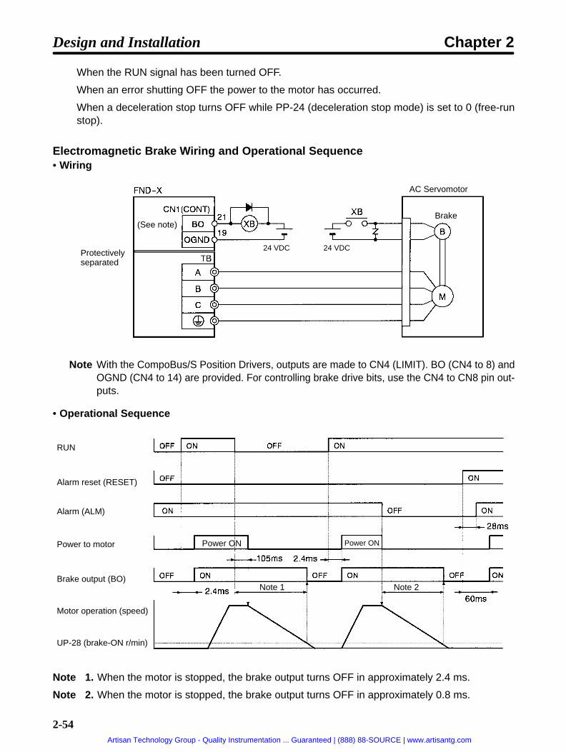
2-54
When the RUN signal has been turned OFF.
When an error shutting OFF the power to the motor has occurred.
When a deceleration stop turns OFF while PP-24 (deceleration stop mode) is set to 0 (free-runstop).
Electromagnetic Brake Wiring and Operational Sequence• Wiring
24 VDC 24 VDC
AC Servomotor
Brake(See note)
Protectivelyseparated
Note With the CompoBus/S Position Drivers, outputs are made to CN4 (LIMIT). BO (CN4 to 8) andOGND (CN4 to 14) are provided. For controlling brake drive bits, use the CN4 to CN8 pin out-puts.
• Operational Sequence
RUN
Alarm reset (RESET)
Alarm (ALM)
Power to motor
Brake output (BO)
Motor operation (speed)
UP-28 (brake-ON r/min)
Power ON Power ON
Note 1 Note 2
Note 1. When the motor is stopped, the brake output turns OFF in approximately 2.4 ms.
Note 2. When the motor is stopped, the brake output turns OFF in approximately 0.8 ms.
Design and Installation Chapter 2
Artisan Technology Group - Quality Instrumentation ... Guaranteed | (888) 88-SOURCE | www.artisantg.com

2-55
Dynamic Brake Wiring and Operational Sequence• Wiring
24 VDC
AC Servomotor
(See note)
Protectivelyseparated
Note With the CompoBus/S Position Drivers, outputs are made to CN4 (LIMIT). BO (CN4 to 8) andOGND (CN4 to 14) are provided. For controlling dynamic brake drive bits, use the CN4 to CN8pin outputs.
• Operational Sequence
RUN
Alarm reset (RESET)
Alarm (ALM)
Power to motor
Brake output (BO)
Motor operation (speed)
Power ON Power ON
DIO CN1-22 CompoBus/S IN1READY READY
• This output turns ON when the input signal processing is completed and the origin search, start, teach,and point selection signal inputs are ready.
• The output turns OFF when position data is taken and positioning begins, and turns ON when the pro-cessing is completed. The time set for HP-46 (positioning completed timer) must be OFF.
• While this signal is OFF, any START signal that is input will be invalid.
Design and Installation Chapter 2
Artisan Technology Group - Quality Instrumentation ... Guaranteed | (888) 88-SOURCE | www.artisantg.com
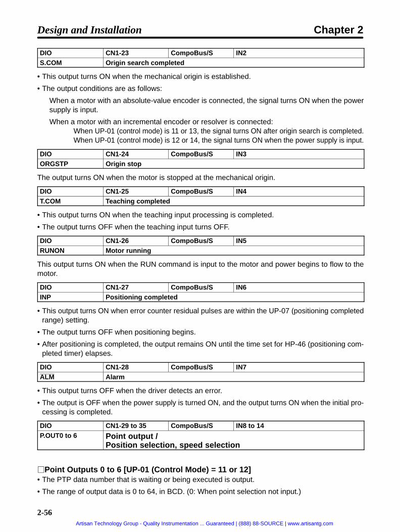
2-56
DIO CN1-23 CompoBus/S IN2S.COM Origin search completed
• This output turns ON when the mechanical origin is established.
• The output conditions are as follows:
When a motor with an absolute-value encoder is connected, the signal turns ON when the powersupply is input.
When a motor with an incremental encoder or resolver is connected:When UP-01 (control mode) is 11 or 13, the signal turns ON after origin search is completed.When UP-01 (control mode) is 12 or 14, the signal turns ON when the power supply is input.
DIO CN1-24 CompoBus/S IN3ORGSTP Origin stop
The output turns ON when the motor is stopped at the mechanical origin.
DIO CN1-25 CompoBus/S IN4T.COM Teaching completed
• This output turns ON when the teaching input processing is completed.
• The output turns OFF when the teaching input turns OFF.
DIO CN1-26 CompoBus/S IN5RUNON Motor running
This output turns ON when the RUN command is input to the motor and power begins to flow to themotor.
DIO CN1-27 CompoBus/S IN6INP Positioning completed
• This output turns ON when error counter residual pulses are within the UP-07 (positioning completedrange) setting.
• The output turns OFF when positioning begins.
• After positioning is completed, the output remains ON until the time set for HP-46 (positioning com-pleted timer) elapses.
DIO CN1-28 CompoBus/S IN7ALM Alarm
• This output turns OFF when the driver detects an error.
• The output is OFF when the power supply is turned ON, and the output turns ON when the initial pro-cessing is completed.
DIO CN1-29 to 35 CompoBus/S IN8 to 14P.OUT0 to 6 Point output /
Position selection, speed selection
Point Outputs 0 to 6 [UP-01 (Control Mode) = 11 or 12]• The PTP data number that is waiting or being executed is output.
• The range of output data is 0 to 64, in BCD. (0: When point selection not input.)
Design and Installation Chapter 2
Artisan Technology Group - Quality Instrumentation ... Guaranteed | (888) 88-SOURCE | www.artisantg.com

2-57
• Point outputs 0 to 3 become the data output for digit 100, and point outputs 4 to 6 become the dataoutput for digit 101.
Example: When point No. 12 is selected.
0 0 1 0 0 1 0
6 5 4 3 2 1 0
0: OFF, 1: ON
Point output
Position Selection 1 to 4 [UP-01 (Control Mode) = 13 or 14]• This is the request signal output for obtaining positioning data.
• Refresh the data for positions 0 to 7 (P.IN 0 to 7) according to the data request signals.
• The output ON time can be set by PP-26 (selection signal output time). Adjust this parameter wheninputting data from a source such as a Programmable Controller.
Design and Installation Chapter 2
Artisan Technology Group - Quality Instrumentation ... Guaranteed | (888) 88-SOURCE | www.artisantg.com

2-58
Control I/O Connections and External Signal Processing (DIO PositionDrivers)
+24 V24 VDC
24 VDC 8 mA
CCW limit input
CW limit input
Origin proximity
RUN
START
Alarm reset
Origin search
+JOG operation
–JOG operation
Teach
Position 7
Point selection 0/ Position 0
STOP
Brake output
Origin searchcompleted
Origin stop
Teachingcompleted
Motor running
Positioningcompleted
Alarm
Point output 0/ Positionselection 1
Point output 6
Output ground
Maximum voltage:24 VDC
Outputcurrent:40 mA
Note 1. The wiring for control inputs P.IN 1 to 6 is omitted. The input circuitry is the same as for P.IN0.Note 2. The wiring for control inputs P.OUT 1 to 5 is omitted. The output circuitry is the same as for
P.OUT 0.
Design and Installation Chapter 2
Artisan Technology Group - Quality Instrumentation ... Guaranteed | (888) 88-SOURCE | www.artisantg.com

2-59
Control I/O Connections and External Signal Processing (CompoBus/SPosition Drivers)
+24 V24 VDC
24 VDC 8 mA
CCW limit input
CW limit input
Origin proximity
Deceleration stop
Brake output
Output ground
Maximum voltage:24 VDC
Outputcurrent:40 mA
8
14
7
Note The Servomotor cannot be driven if the deceleration stop signal if OFF for the external controlinput (CN4-4) or the CompoBus/S input (OUT7).
Design and Installation Chapter 2
Artisan Technology Group - Quality Instrumentation ... Guaranteed | (888) 88-SOURCE | www.artisantg.com

2-60
Example: Connecting DIO Position Drivers to a ProgrammableController
24 VDC +24 V
ProgrammableController OutputUnit
ProgrammableController InputUnit
FND-X Position Driver
Brake
Design and Installation Chapter 2
Artisan Technology Group - Quality Instrumentation ... Guaranteed | (888) 88-SOURCE | www.artisantg.com

2-61
Example: Connecting DIO Position Drivers to Thumbwheel Switch(Positioning Data Designation by Direct Input)
Position data100 digit
Position data101 digit
Position data106 digit
Position data107 digit
Sign +/–INC/ABS
Speed data100 digit
Speed data101 digit
FND-X Position Driver+24 V24 VDC
Note 1. The wiring for position datadigits 102 to 105 is omitted,but it is the same as for theother digits.
Note 2. The wiring for control outputpins 21 to 28 is omitted.
Note 3. Do not remove the reverse-current prevention diodeseven when outputting theposition and speed datafrom PLC Output Units.
Design and Installation Chapter 2
Artisan Technology Group - Quality Instrumentation ... Guaranteed | (888) 88-SOURCE | www.artisantg.com

2-62
2-2-3 Wiring T erminal BlocksProvide proper wire diameters, ground systems, and noise resistance when wiring terminal blocks.
Wiring FND-X06 to X25 Terminal Blocks
Power supply inputs
Regeneration Resistorconnection terminals
Power cable
Red
White
Blue or Black
Green
Design and Installation Chapter 2
Artisan Technology Group - Quality Instrumentation ... Guaranteed | (888) 88-SOURCE | www.artisantg.com

2-63
Terminallabel
Name Function
R Power supply input The commercial power supply input terminals forthe main circuit and the control circuits.
FND-XH-: Single-phase 200/240 VAC (170S
FND-XH-: Single- hase 200/240 VAC (170to 264 V) 50/60 HzFND-XL-: Single-phase 100/115 VAC (85 to127 V) 50/60 Hz
P Main circuit DC outputRegenerative Resistor connection terminals
Connector terminals for the R88A-RR20030 orR88A-RR40030 Regenerative Resistor, which will
JRegenerative Resistor connection terminals R88A RR40030 Regenerative Resistor, which will
be required if there is excessive regenerative ener-gy. (see note)
N Main circuit DC output Main circuit DC output terminal.
A Phases A and U motor output Red These are the output terminals to the Ser-vomotor. Be careful to wire them correctly.
OMNUC Servomotors can be connectedh i l i h R88A CAUB Phases B and V motor output White to these terminals with R88A-CAU
Cable (for U-series Servomotors) orR88A-CAH Cable (for H-series Servo-motors).
C Phases C and W motor output Blueorblack
motors).
OMRON does not provide a cable to con-nect these terminals to OMNUC M-seriesServomotors, so the user must provide anappropriate cable if an M-series Servomo-tor is used.
Frame ground Green Ground (to 100 Ω or less). This terminal isused for both motor output and power sup-ply input.
Note Refer to 3-10 Regenerative Energy Absorption for the methods to calculate regenerative energy.
Design and Installation Chapter 2
Artisan Technology Group - Quality Instrumentation ... Guaranteed | (888) 88-SOURCE | www.artisantg.com

2-64
Wiring FND-X50 Terminal BlocksProtectivelyseparated
Control circuit powersupply inputs
Power cable
Red
Whi
te
Blu
e or
Bla
ck
Gre
en
RegenerationResistor
Ground (100 Ω or less)Main powersupply inputs
Design and Installation Chapter 2
Artisan Technology Group - Quality Instrumentation ... Guaranteed | (888) 88-SOURCE | www.artisantg.com

2-65
Terminallabel
Name Function
R0 Control circuit power supply input The commercial power supply input terminals forthe control circuits.
S0the control circuits.
Single-phase 200/240 VAC (170 to 264 V) 50/60 Hz
R Main power supply input The commercial power supply input terminals forh i i iS
y ythe main circuits.
T Three-phase 200/240 VAC (170 to 264 V) 50/60 Hz
P Main circuit DC outputRegenerative Resistor connection terminals
Connector terminals for the R88A-RR20030 orR88A-RR40030 Regenerative Resistor which will
J1Regenerative Resistor connection terminals R88A-RR40030 Regenerative Resistor, which will
be required if there is excessive regenerative ener-I thi th h t b b t JP1J2 gy. In this case, remove the short bar between JP1
and JP2. (see note)N Main circuit DC output Main circuit DC output terminal.
MC Not used. Do not connect anything to these terminals and doh h b b BI d BICOM
y gnot remove the short bar between BI1 and BI2.
BO
BI1BI2A Phases A and U motor output Red These are the output terminals to the Ser-
vomotor. Be careful to wire them correctly.
OMNUC Servomotors can be connected toB Phases B and V motor output White
OMNUC Servomotors can be connected tothese terminals with R88A-CAUB Cable(for U-series Servomotors).
O OC Phases C and W motor output Blueorblack
OMRON does not provide a cable to con-nect these terminals to OMNUC M-seriesServomotors, so the user must provide anappropriate cable if an M-series Servomo-tor is used.
Frame ground Green Ground (to 100 Ω or less). This terminal isused for both motor output and power sup-ply input.
Note Refer to 3-10 Regenerative Energy Absorption for the methods to calculate regenerative energy.
Design and Installation Chapter 2
Artisan Technology Group - Quality Instrumentation ... Guaranteed | (888) 88-SOURCE | www.artisantg.com

2-66
Terminal Block Current and Wire SizesThe following table shows the rated effective currents flowing to the Position Driver’s terminal block, andalso the sizes of the electrical wires.
Position Drivers with 200-VAC Input (FND-X H-)Driver FND-X06H- FND-X12H- FND-X25H- FND-X50H-Main power sup-
l i iEffective current 2.1 A 4.9 A 10.1 A 16 A
ply input termi-nals (R S T)
Wire size 0.75 mm2 1.25 mm2nals (R, S, T)
Tightening torque 1.3 N⋅mControl circuitpower supply in
Effective current --- 0.35 Apower supply in-put terminals Wire size --- 0.75 mm2
ut terminals(R0, S0) Tightening torque --- 1.3 N⋅mMotor output ter-minals (A B C
Effective current 1.4 A 3.4 A 5.7 A 14.1 Aminals (A, B, C,PE) Wire size 0.75 mm2 1.25 mm2 2.0 mm2PE)
Tightening torque 1.3 N⋅m
Frame groundi l (PE)
Wire size 0.75 mm2 1.25 mm2 2.0 mm2gterminal (PE) Tightening torque 1.3 N⋅m
Position Drivers with 100-VAC Input (FND-X L-)Driver FND-X06L- FND-X12L-Main power supply in-
i l (R S)Effective current 2.9 A 3.3 Ay
put terminals (R, S) Wire size 0.75 mm2
Tightening torque 1.3 N⋅mMotor output terminals (A B C PE)
Effective current 1.4 A 2.1 A(A, B, C, PE) Wire size 0.75 mm2
Tightening torque 1.3 N⋅mFrame ground terminal(PE)
Wire size 0.75 mm2g(PE) Tightening torque 1.3 N⋅m
Wire Sizes and Allowable CurrentThe following table shows allowable currents when there are three electrical wires. Use values equal toor lower than the specified values.
Heat-resistant Vinyl Wiring, UL1007, Rated Temperature 80 °C (Reference Value)AWG size Nominal cross-
sectional area( 2)
Configuration(wires/mm 2)
Conductiveresistance
(Ω/k )
Allowable current (A) forambient temperature
(mm2)( )
(Ω/km) 40°C 50°C 60°C20 0.5 19/0.18 39.5 6.6 5.6 4.5
--- 0.75 30/0.18 26.0 8.8 7.0 5.5
18 0.9 37/0.18 24.4 9.0 7.7 6.0
16 1.25 50/0.18 15.6 12.0 11.0 8.5
14 2.0 7/0.6 9.53 23 20 16
12 3.5 7/0.8 5.41 33 29 24
10 5.5 7/1.0 3.47 43 38 31
Design and Installation Chapter 2
Artisan Technology Group - Quality Instrumentation ... Guaranteed | (888) 88-SOURCE | www.artisantg.com

2-67
2-2-4 Wiring for Noise Resistance
Wiring Method for FND-X06 to -X25Noise resistance will vary greatly depending on the wiring method used. Resistance to noise can beincreased by paying attention to the items described below.
R
S
A
BC
CN2
M
NFB
3.5mm2 2 mm2 min.
1
2
3
4
NF
E
X1 TB TB
AC power supply
(Lightning surgeprotection)
Contactor
Metal duct
Fuse
(Electric shock noiseprotection)
Ground plateControl boardground
Controller power supply
Thick power line(3.5 mm2)
Machineground
No-fusebreaker
FND-X R88M-U/H/M
(Faulty grounding, short-circuit protection) (Noise
protection)
(Electrical shock,noise protection)
Surgeabsorber
(Noiseprotection)
Noise filter
Ground (to 100 Ωor less)
• Ground the motor’s frame to the machine ground when the motor is on a movable shaft.
• Use a grounding plate for the frame ground for each Unit, as shown in the illustration, and ground to asingle point.
• Use ground lines with a minimum thickness of 3.5 mm2, and arrange the wiring so that the ground linesare as short as possible.
• If no-fuse breakers are installed at the top and the power supply line is wired from the lower duct, usemetal tubes for wiring and make sure that there is adequate distance between the input lines and theinternal wiring. If input and output lines are wired together, noise resistance will decrease.
• No-fuse breakers, surge absorbers, and noise filters (NF) should be positioned near the input terminalblock (ground plate), and I/O lines should be isolated and wired using the shortest means possible.
• Wire the noise filter as shown at the left in the following illustration. The noise filter should be installedat the entrance to the control panel whenever possible.
1
2
3
4
NF E
1
2
3
4
NF E
Right: Separate input and output
AC input
Ground
AC output
Wrong: Noise not filtered effectively
AC input
Ground
AC output
Design and Installation Chapter 2
Artisan Technology Group - Quality Instrumentation ... Guaranteed | (888) 88-SOURCE | www.artisantg.com

2-68
• Use twisted-pair cables for the power supply cables whenever possible, or bind the cables.
PositionDriver
Binding
R
S
or PositionDriver
Twisted Wires Binding
• Separate power supply cables and signal cables when wiring.
Wiring Method for FND-X50H-
Noise resistance will vary greatly depending on the wiring method used. Resistance to noise can beincreased by paying attention to the items described below.
AC power supply
(Lightning surgeprotection)
Contactor Metal duct
Fuse
(Electricshock noiseprotection)
Groundplate Control board
ground
Controller power supply
Thick power line(3.5 mm2)
Machineground
No-fusebreaker
(Faulty grounding,short-circuitprotection)
(Noiseprotection)
(Electrical shock,noise protection)
Surgeabsorber
(Noiseprotection)
Noise filter
Ground (to 100 Ω or less)
Protectivelyseparated
CN2(M.SEN)
• Ground the motor’s frame to the machine ground when the motor is on a movable shaft.
• Use a grounding plate for the frame ground for each Unit, as shown in the illustration, and ground to asingle point.
• Use ground lines with a minimum thickness of 3.5 mm2, and arrange the wiring so that the ground linesare as short as possible.
• If no-fuse breakers are installed at the top and the power supply line is wired from the lower duct, usemetal tubes for wiring and make sure that there is adequate distance between the input lines and theinternal wiring. If input and output lines are wired together, noise resistance will decrease.
• No-fuse breakers, surge absorbers, and noise filters (NF) should be positioned near the input terminalblock (ground plate), and I/O lines should be isolated and wired using the shortest means possible.
Design and Installation Chapter 2
Artisan Technology Group - Quality Instrumentation ... Guaranteed | (888) 88-SOURCE | www.artisantg.com

2-69
• Wire the noise filter as shown at the left in the following illustration. The noise filter should be installedat the entrance to the control panel whenever possible.
Right: Separate input and output Wrong: Noise not filtered effectively
AC inputs
Ground
AC outputs AC inputs
Ground
AC outputs
• Use twisted-pair cables for the power supply cables whenever possible, or bind the cables.
PositionDriver
PositionDriver
Binding
Twisted Wires Binding
• Separate power supply cables and signal cables when wiring.
Selecting ComponentsThis section explains the standards for selecting the required components for improving noise resis-tance. When selecting components, it is necessary to understand characteristics such as the capacity,performance, applicable range, and so on. For details regarding any of the recommended productslisted in the tables below, contact their respective makers.
No-fuse BreakersWhen selecting no-fuse breakers, take into consideration the maximum output current and the inrushcurrent. The momentary maximum output for a servo system is approximately three times that of therated output, and a maximum output of three seconds can be executed. Therefore, select no-fusebreakers with an operating time of at least five seconds at 300% of the rated maximum output. General-purpose and low-speed no-fuse breakers are generally suitable. Refer to the table in 2-2-3 Wiring Ter-minal Blocks for the power supply input currents for each motor, and then add the current consumptionfor the number of shafts, other controllers, etc., to make the selection.
The Position Driver inrush current flows at a maximum of 50 A for 20 ms when 200 V is input. With low-speed no-fuse breakers, a inrush current 7 to 8 times the rated current flows for 0.1 second. When mak-ing the selection, take into consideration the entire inrush current for the system.
Design and Installation Chapter 2
Artisan Technology Group - Quality Instrumentation ... Guaranteed | (888) 88-SOURCE | www.artisantg.com

2-70
Surge AbsorbersUse surge absorbers to absorb surges from power supply input lines due to lightning, abnormal volt-ages, etc. When selecting surge absorbers, take into account the varistor voltage, the amount of surgeimmunity, and the amount of energy resistance. For 200-VAC systems, use a varistor voltage of 470 V.The surge absorbers shown in the following table are recommended.
Maker Model Varistorvoltage
Max. limitvoltage
Surgeimmunity
Energyresistance
Fusecapacity
Type
MatsushitaEl i
ERZC10DK471 (W) 470 V 775 V 1,250 A 45J 3 to 5 A TesterElectricIndustrial
ERZC14DK471 (W) 470 V 775 V 2,500 A 80J 3 to 10 AIndustrial
ERZC20DK471 (W) 470 V 775 V 4,000 A 150J 5 to 15 A
ERZC20EK471 (W) 470 V 775 V 5,000 A 150J --- Block
IshizukaEl i
Z10L471 470 V 773 V 1,000 A 15Ws 3 to 5 A TesterElectric Z15L471 470 V 738 V 1,250 A 20Ws 3 to 5 A
Z21L471 470 V 733 V 3,000A 30Ws 5 to 10 A
Z25M471S 470 V 810 V 10,000 A 235J --- Block
OkayaEl i
RAV-781 BWZ-2A --- 783 V 1,000 A --- --- BlockyElectricIndustrial
RAV-781 BXZ-2A --- 783 V 1,000 A --- ---Industrial
R-A-V-401-621BYR-2 --- 620 V 1,000 A --- ---
Note 1. The “(W)” for the Matsushita Electric Industrial products indicates that they are UL- and CSA-approved products.
Note 2. Refer to manufacturers documentation for operating details.
Note 3. The surge immunity is for a standard impulse current of 8/20 µs. If pulses are wide, either de-crease the current or change to a larger-capacity surge absorber.
Note 4. The energy resistance is the value at 2 ms. At 700 V or less, high-energy pulses may not beavoidable. In that case, use an insulated transformer or reactor for surge absorption.
Noise Filters for Power Supply Input• Use a noise filter for external noise attenuation and for the reduction of radiation noise from the Posi-
tion Driver.
• Select a noise filter with a rated current of at least double that of the Driver’s input current.
• The noise filters shown in the following table can be used for 40-dB attenuation of noise between200 kHz and 30 MHz.
Maker Model Rated current RemarksTokin LF-210N 10 A For single phase
LF-215N 15 A
g
LF-220N 20 ALF-315K 15 A For three phase
LF-325K 25 A
Note 1. For attenuating noise in a low-frequency band of less than 200 kHz, use an insulated trans-former and a noise filter.
Note 2. For attenuating noise in a high-frequency band of more than 30 MHz, use a ferrite core and ahigh-frequency noise filter employing a through-type capacitor.
Design and Installation Chapter 2
Artisan Technology Group - Quality Instrumentation ... Guaranteed | (888) 88-SOURCE | www.artisantg.com

!
2-71
Noise Filters for Servomotor Output• For Servomotor output lines, use a filter type without a built-in capacitor.
• The following table shows recommended noise filters for Servomotor output lines.
Maker Model Rated current RemarksTokin LF-310KA 10 A 3-phase block noise filter
LF-320KA 20 AESD-R-47B --- EMI core for radiation
noiseFuji Electrochemical RN80UD --- 10 turns for radiation
noise
Note The same noise filter cannot be used for Servomotor output lines as for the power supply.
Caution Ordinary noise filters are created for a power supply frequency of 50/60 Hz, so con-necting an output of 10 kHz (the Position Driver’s PWM frequency) can generate anextremely high (approximately 100 time the normal) leakage current flow to the ca-pacitor in the noise filter and cause damage to the Position Driver.
Surge KillersInstall surge killers for loads that have induction coils, such as relays, solenoids, brakes, clutches, etc.The following table shows types of surge killers and recommended products.
Type Features Recommended productsDiode Diodes are relatively small devices such as relays used
for loads when reset time is not an issue. The reset timeis increased because the surge voltage is the lowestwhen power is cut OFF. Used for 24/48-VDC systems.
Use a fast-recovery diode with ashort reverse recovery time.
Fuji Electric Co., ERB44-06 or equiv-alent
ThyristororVaristor
Thyristor and varistor are used for loads when inductioncoils are large, as in electromagnetic brakes, solenoids,etc., and when reset time is an issue. The surge voltagewhen power is cut OFF is approximately 1.5 times thatof the varistor.
Select varistor voltage as follows:
24-VDC system varistor: 39 V100-VDC system varistor: 200 V100-VAC system varistor: 270 V200-VAC system varistor: 470 V
Capacitor+ resistor
Use capacitors and resistors for vibration absorption ofsurge when power is cut OFF. The reset time can beshortened by proper selection of the capacitor or resis-tor.
Okaya Electric Industrial Co.
CR-50500 0.5 µF-50 ΩCRE-50500 0.5 µF-50 ΩS2-A-0 0.2 µF-500 Ω
Note Thyristors and varistors are made by the following companies. Refer to manufacturers documen-tation for operating details.Thyristors: Ishizuka Electronics Co.Varistors: Ishizuka Electronics Co., Matsushita Electric Industrial Co.
Design and Installation Chapter 2
Artisan Technology Group - Quality Instrumentation ... Guaranteed | (888) 88-SOURCE | www.artisantg.com

2-72
ContactorsWhen selecting contactors, take into consideration the circuit’s inrush current and the momentary maxi-mum current. The Position Driver inrush current is 50 A, and the momentary maximum current isapproximately twice the rated current. The following table shows the recommended contactors.
Maker Model Ratedcurrent
Momentary maxi-mum current
Coil voltage
OMRON G6C-2BND 10 A --- 24 VDCLY2-D 10 A --- 24 VDC
G7L-2A-BUBJ 25 A --- 24 VDC, 200 to 240 VACJ7AN-E3 15 A 120 A 24 VDCLC1D25106 26 A --- 200 VACLP1D25106 26 A --- 24 VDC
Leakage Breakers• Select leakage breakers designed for inverters.
• Since switching operations take place inside the Position Driver, high-frequency current leaks fromthe armature of the Servomotor. With inverter leakage breakers, high-frequency current is not de-tected, preventing the breaker from operating due to leakage current.
• When selecting leakage breakers, also remember to add the leakage current from devices other thanthe Servomotor, such as machines using a switching power supply, noise filters, inverters, and so on.
• For detailed information on how to select leakage breakers, refer to the catalogs provided by themanufacturers.
• The following table shows the Servomotor leakage currents for each Driver model.
Driver model Leakage current (direct)(including high-frequency current)
Leakage current (resistor-capacitor,in commercial power supply fre-
quency range)FND-X06/X12 35 mA0-P 2 mArms
FND-X25 40 mA0-P 2 mArms
FND-X50H 120 mA0-P 3 mArms
Note 1. Leakage current values shown above are for motor power lines of 10 m or less. The values willchange depending on the length of power cables and the insulation.
Note 2. Leakage current values shown above are for normal temperatures and humidity. The valueswill change depending on the temperature and humidity.
Improving Encoder and Resolver Cable Noise ResistanceSignals from the encoder are A-phase, B-phase, or S-phase. The A-phase and B-phase frequency is154 kHz, and the S-phase baud rate is 616K bits/s.
Signals from the resolver are analog voltage signals.
Follow the wiring methods outlined below to improve encoder/resolver noise resistance.
• Be sure to use dedicated encoder and resolver cables.
• If lines are interrupted in the middle, be sure to connect them with connectors, making sure that thecable insulation is not peeled off for more than 50 mm. In addition, be sure to use shielded wire.
Design and Installation Chapter 2
Artisan Technology Group - Quality Instrumentation ... Guaranteed | (888) 88-SOURCE | www.artisantg.com

2-73
• Do not coil cables. If cables are long and are coiled, mutual induction and inductance will increase andwill cause malfunctions. Be sure to use cables fully extended.
• When installing noise filters for encoder cables, use clamp filters. The following table shows the rec-ommended clamp filter models. (Do not use the clamp filters for resolver cables.)
Maker Name ModelTokin EMI core ESD-QR-25-1TDK Clamp filter ZCAT2032-0930
ZCAT3035-1330ZCAT2035-0930A
• Do not wire the encoder or resolver cable in the same duct as power cables and control cables forbrakes, solenoids, clutches, and valves.
Improving Control I/O Signal Noise ResistancePosition can be affected if control I/O signals are influenced by noise. Follow the methods outlined be-low for the power supply and wiring.
• Use completely separate power supplies for the control power supply (especially 24 VDC) and theexternal operation power supply. In particular, be careful not to connect two power supply groundwires. Install a noise filter on the primary side of the control power supply.
• If the control power supply wiring is long, noise resistance can be improved by adding 1-µF laminatedceramic capacitors between the control power supply and ground at the Position Driver input sectionand the controller output section.
• Use shielded cable for the control cables, and connect the shield to the connector frame at the Driver.
2-2-5 Wiring Products Conforming to EMC DirectivesPosition Drivers will meet the requirements of the EMC Directives if they are connected to a U-SeriesServomotor that conforms to the EC directives and are wired under the conditions described in this sec-tion. If the connected devices, wiring, and other conditions cannot be made to fulfill the installation andwiring conditions when the product is incorporated into a machine, the compliance of the overall ma-chine must be confirmed.
The following conditions must be met to conform to EMC Directives.
• The Position Driver must be installed in a metal case (control panel).
• Noise filters and surge absorbers must be installed on all power supply lines.
• Shielded cables must be used for all I/O signal lines and encoder lines. (Use tin-plated, soft copperwires for the shield weaving.)
• All cables leaving the control panel must be wired in metal ducts or conduits with blades.
• Ferrite cores must be attached to the shielded cable and the shield must be clamped directly to theground plate to ground it.
Design and Installation Chapter 2
Artisan Technology Group - Quality Instrumentation ... Guaranteed | (888) 88-SOURCE | www.artisantg.com

2-74
Wiring Methods
FND-X06 to X25 Position Drivers
DIO: 5 m max.CompoBus/S: 100 m max.
0.5 mmax.
AC powersupply Contactor
Metalduct orconduit
Ground (100 Ω max.)
Metal plate
Control panel
Brakepowersupply
Noisefilter
Surgeabsorber
Controllerpowersupply
Controller
Grounding plate
Controller
Clamp
Ferritecore
Metalduct orconduit
Ferritecore
Clamp
Note 1. The cable winding for the ferrite core must be 1 turn.
Note 2. Remove the sheathes from the cables at the clamps and ground them directly to the metalplate at the clamps.
Note 3. For DIO Position Drivers, remove the sheath from control cables and connect the shielddirectly to the metal plate. For CompoBus/S Position Drivers, place the control cables inmetal ducts or conduits and connect the duct or conduit directly to the metal plate.
Clamp
Driver FG
Device containing Servomotor
R88M-U conformingto EC Directives
NFB
0.5 mmax.
0.5 mmax.
Ferritecore
Protectivelyseparated
Design and Installation Chapter 2
Artisan Technology Group - Quality Instrumentation ... Guaranteed | (888) 88-SOURCE | www.artisantg.com

2-75
FND-X50H- Position Drivers
DIO: 5 m max.CompoBus/S: 100 m max.
0.5 mmax.
AC powersupply Contactor
Metalduct orconduit
Ground (100 Ω max.)
Metal plate
Control panel
Brake pow-er supply
Noisefilter
Surgeabsorber
Controllerpowersupply
Controller
Grounding plate
Controller
Clamp
Ferritecore
Metalduct orconduit
Ferritecore
Clamp
Note 1. The cable winding for the ferrite core must be 1 turn.
Note 2. Remove the sheathes from the cables at the clamps and ground them directly to the metalplate at the clamps.
Note 3. For DIO Position Drivers, remove the sheath from control cables and connect the shielddirectly to the metal plate. For CompoBus/S Position Drivers, place the control cables inmetal ducts or conduits and connect the duct or conduit directly to the metal plate.
Clamp
Driver FG
Device containing Servomotor
NFB
0.5 mmax.
0.5 mmax.
Ferritecore
R88M-U conformingto EC Directives
Protectivelyseparated
All Position Drivers• Ground the motor’s frame to the machine ground when the motor is on a movable shaft.
• Connect the frame ground for each Unit as shown in the diagram and using ground lines as short aspossible.
• If no-fuse breakers (MCCB) are installed at the top and the power supply line is wired from the lowerduct, use metal tubes for wiring or make sure that there is adequate distance between the input linesand the internal wiring. If input and output lines are wired together, noise resistance will decrease.
• No-fuse breakers (MCCB), surge absorbers, and noise filters (NF) should be positioned near the inputterminal block (ground plate), and I/O lines should be isolated and wired using the shortest meanspossible.
Noise Filters• Remove the coating (or mask when coating) from the panel area to which the Position Driver and noise
filters are mounted to improve electrical conductivity.
• Locate noise filters as close to the Position Driver as possible and keep the wiring distance betweenthe noise filters and Position Driver as short as possible.
Design and Installation Chapter 2
Artisan Technology Group - Quality Instrumentation ... Guaranteed | (888) 88-SOURCE | www.artisantg.com

2-76
• Wire the noise filter as shown at the left in the following illustrations.
1
2
4
6
NF 5
1
3
4
6
NF 5
Good: Separate input and output
AC inputs
Ground
AC outputs
NO: Noise not filtered effectively
AC inputs
Ground
AC outputs
2
E
2
E
• Use twisted-pair cables for the power supply cables whenever possible, or bind the cables.
PositionDriver
Binding
R0
S0
PositionDriver
ST
Twisted Wires BindingR
• Separate power supply cables and signal cables when wiring.
FND-X06 to X25 Position Drivers FND-X50H- Position Drivers
Installation panel
AC power
Contactor
Primary
Noise filter
Secondary
Main power supply andcontrol circuit powersupply
0.5 m max.
FND-X
Do not coat mount-ing surface.
Installation panel
AC power
Contactor
Primary
Noise filter
Secondary
Main power supply
0.5 m max.
FND-X
Do not coat mount-ing surface.
Control circuitpower supply
Connecting Cables• Used shielded cables for control cables and encoder cables.
• All cables leaving the control panel must be wired in metal ducts or conduits with blades.
• All power cables and encoder cables to the Servomotors must be 20 m or less.
Design and Installation Chapter 2
Artisan Technology Group - Quality Instrumentation ... Guaranteed | (888) 88-SOURCE | www.artisantg.com

2-77
• Remove the sheathes from the control cables and encoder cables at the clamps and ground the shielddirectly at the clamps.
• Ground the metal ducts and conduits with blades
• Attach ferrite cores on all cables as near as possible to the Position Driver.
Shield Connections
Installation panel Installation panel
0.5 m max.
0.5 m max.0.5 m max.
Clamp Clamp
Clamp
Host controller
Do not coat orplate mountingsurface.
Detail at Clamps
FND-X
Control Panel StructureAny gaps in the cable entrances, mounting screws, cover, or other parts of a control panel can allowelectric waves to leak from or enter the control panel. The items described in this section must be abidedby in panel design and selection to ensure that electric waves cannot leak or enter the control panel.
Case Structure• Use a metal control panel with welded joints on the top, bottom, and all sides. The case must be electri-
cally conductive.
Design and Installation Chapter 2
Artisan Technology Group - Quality Instrumentation ... Guaranteed | (888) 88-SOURCE | www.artisantg.com
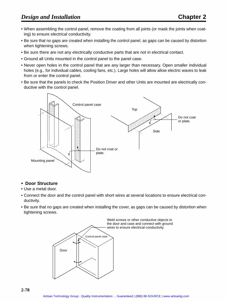
2-78
• When assembling the control panel, remove the coating from all joints (or mask the joints when coat-ing) to ensure electrical conductivity.
• Be sure that no gaps are created when installing the control panel, as gaps can be caused by distortionwhen tightening screws.
• Be sure there are not any electrically conductive parts that are not in electrical contact.
• Ground all Units mounted in the control panel to the panel case.
• Never open holes in the control panel that are any larger than necessary. Open smaller individualholes (e.g., for individual cables, cooling fans, etc.). Large holes will allow allow electric waves to leakfrom or enter the control panel.
• Be sure that the panels to check the Position Driver and other Units are mounted are electrically con-ductive with the control panel.
Control panel case
Mounting panel
Do not coat orplate.
Top
Side
Do not coator plate.
Door Structure• Use a metal door.
• Connect the door and the control panel with short wires at several locations to ensure electrical con-ductivity.
• Be sure that no gaps are created when installing the cover, as gaps can be caused by distortion whentightening screws.
Weld screws or other conductive objects tothe door and case and connect with groundwires to ensure electrical conductivity.
Control panel case
Door
Design and Installation Chapter 2
Artisan Technology Group - Quality Instrumentation ... Guaranteed | (888) 88-SOURCE | www.artisantg.com

2-79
Selecting ComponentsThis section describes standards to be considered when selecting components to be connected toreduce noise. Select components after reviewing characteristics such as capacities, performance, andapplication ranges. Recommended components are listed below for reference. For further details, con-sult the manufacturer.
No-fuse Breakers (MCCB)When selecting no-fuse breakers, take into consideration the maximum output current and the inrushcurrent.
The momentary maximum output for a servo system is approximately three times that of the rated out-put, and a maximum output of three seconds can be executed. Therefore, select no-fuse breakers withan operating time of at least five seconds at 300% of the rated maximum output. General-purpose andlow-speed no-fuse breakers are generally suitable. Refer to the table in 2-2-3 Wiring Terminal Blocks forthe power supply input currents for each motor. Be sure to add the current consumption for the numberof shafts, other controllers, etc., to make the selection.
The Position Driver inrush current flows at a maximum of 50 A for 20 ms when 200 V is input. With low-speed no-fuse breakers, a inrush current 7 to 8 times the rated current flows for 0.1 second. When mak-ing the selection, take into consideration the entire inrush current for the system.
Surge AbsorbersUse surge absorbers to absorb surges from power supply input lines due to lightning, abnormal volt-ages, etc. When selecting surge absorbers, take into account the varistor voltage, the amount of surgeimmunity, and the amount of energy resistance. For 200-VAC systems, use a varistor voltage of 470 V.The surge absorbers shown in the following table are recommended.
Maker Model Max. limitvoltage
Surgeimmunity
Type Remarks
OkayaEl i I d
R.A.V-781BYZ-2 783 V 1,000 A Block For power supply lineyElectric Ind. R.A.V-781BXZ-4 783 V 1,000 A For power supply line
groundNote 1. Refer to manufacturer’s documentation for operating details.
Note 2. The surge immunity is for a standard impulse current of 8/20 µs. If pulses are wide, either decrease thecurrent or change to a larger-capacity surge absorber.
Ferrite CoresMaker Model
TDK ZCAT305-1330
Power Supply Input Noise FiltersMaker Motor capacity Model Remarks
Soshin Electric Co., Ltd. 30 to 500 W NF2010A-PI Single-phase, 10 A,
750 to 1,000 W NF2015A-PI Single-phase, 15 A1.5 to 2 kW HF3010A-PI Three-phase, 10 A
Design and Installation Chapter 2
Artisan Technology Group - Quality Instrumentation ... Guaranteed | (888) 88-SOURCE | www.artisantg.com
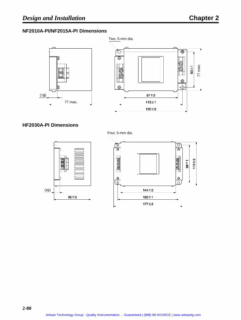
2-80
NF2010A-PI/NF2015A-PI Dimensions
Two, 5-mm dia.
77 max.
77 m
ax.
HF2030A-PI Dimensions
Four, 5-mm dia.
Design and Installation Chapter 2
Artisan Technology Group - Quality Instrumentation ... Guaranteed | (888) 88-SOURCE | www.artisantg.com

2-81
Surge KillersInstall surge killers for loads that have induction coils, such as relays, solenoids, brakes, clutches, etc.The following table shows types of surge killers and recommended products.
Type Features Recommended productsDiode Diodes are relatively small devices such as relays used
for loads when reset time is not an issue. The reset timeis increased because the surge voltage is the lowestwhen power is cut off. Used for 24/48-VDC systems.
Use a fast-recovery diode with ashort reverse recovery time.
Fuji Electric Co., ERB44-06 or equiv-alent
ThyristororVaristor
Thyristor and varistor are used for loads when inductioncoils are large, as in electromagnetic brakes, solenoids,etc., and when reset time is an issue. The surge voltagewhen power is cut off is approximately 1.5 times that ofthe varistor.
Select varistor voltage as follows:
24-VDC system varistor: 39 V100-VDC system varistor: 200 V100-VAC system varistor: 270 V200-VAC system varistor: 470 V
Capacitor+ resistor
Use capacitors and resistors for vibration absorption ofsurge when power is cut off. The reset time can beshortened by proper selection of the capacitor or resis-tor.
Okaya Electric Ind.
CR-50500 0.5 µF-50 ΩCRE-50500 0.5 µF-50 ΩS2-A-0 0.2 µF-500 Ω
Note Thyristors and varistors are made by the following companies. Refer to manufacturer’s documentation foroperating details. Thyristors: Ishizuka Electronics Co.
Varistors: Ishizuka Electronics Co., Matsushita Electric Parts
ContactorsWhen selecting contactors, take into consideration the circuit’s inrush current and the momentary maxi-mum current. The Position Driver inrush current is 50 A, and the momentary maximum current isapproximately twice the rated current. The following table shows the recommended contactors.
Maker Model Rated current Coil voltageOMRON LC1D25106 26 A 200 VAC
LC1D40116 35 ALC1D50116 50 ALC1D80116 80 ALP1D25106 26 A 24 VDC
LP1D40116 35 ALP1D50116 50 ALP1D80116 80 A
Leakage Breakers• Select leakage breakers designed for inverters.
• Switching operations take place inside the Position Driver, causing high-frequency current to leakfrom the armature of the Servomotor. With inverter leakage breakers, high-frequency current is notdetected, preventing the breaker from operating due to leakage current.
• When selecting leakage breakers, also remember to add the leakage current from devices other thanthe Servomotor, such as machines using a switching power supply, noise filters, inverters, and so on.
• For detailed information about the selection methods of leakage breakers, refer to catalogs providedby manufacturers.
Design and Installation Chapter 2
Artisan Technology Group - Quality Instrumentation ... Guaranteed | (888) 88-SOURCE | www.artisantg.com

2-82
• The following table shows the Servomotor leakage currents for each Position Driver.
Driver Leakage current (resistor)(including high-frequency current)
Leakage current (resistor-capacitor,in commercial power supply fre-
quency range)FND-X06/X12 35 mA0-P 2 mArms
FND-X25 40 mA0-P 2 mArms
FND-X50H 120 mA0-P 3 mArms
Note 1. Leakage current values shown above are for motor power lines of 10 m or less. The values will changedepending on the length of power cables and the insulation.
Note 2. Leakage current values shown above are for room temperature and humidity. The values will changedepending on the temperature and humidity.
Improving Encoder/Resolver Cable Noise ResistanceSignals from the encoder are either A, B, or S phase. The frequency for A- or B-phase signals is 154 kHzand the transmission speed for S-phase signals is 616 kbps. The Resolvers use analog voltage signals.Follow the wiring methods outlined below to improve encoder/resolver noise resistance.
• Be sure to use dedicated encoder/resolver cables.
• If lines are interrupted in the middle, connect them with connectors, making sure that the cable insula-tion is not peeled off for more than 50 mm. In addition, be sure to use shielded wire.
• Do not coil cables. If cables are long and are coiled, mutual induction and inductance will increase andwill cause malfunctions. Be sure to use cables fully extended.
• When installing noise filters for encoder cables, use clamp filters. The following table shows the rec-ommended clamp filter models. Do not use these with resolver cables.
• Do not wire the encoder/resolver cable in the same duct as power cables and control cables forbrakes, solenoids, clutches, and valves.
Improving Control I/O Signal Noise ResistancePosition can be affected if control I/O signals are influenced by noise. Follow the methods outlined be-low for the power supply and wiring.
• Use completely separate power supplies for the control power supply (especially 24 VDC) and theexternal operation power supply. In particular, be careful not to connect two power supply groundwires. Install a noise filter on the primary side of the control power supply.
• If the control power supply wiring is long, noise resistance can be improved by adding 1-µF laminatedceramic capacitors between the control power supply and ground at the Position Driver input sectionand the controller output section.
• Use twisted-pair shielded cables for control cables, and the shield wire to the connector frame at thePosition Driver.
Design and Installation Chapter 2
Artisan Technology Group - Quality Instrumentation ... Guaranteed | (888) 88-SOURCE | www.artisantg.com

2-83
Harmonic Current Suppression• An AC Reactor that controls steep current changes is used for suppressing harmonic current.
• Guidelines issued by MITI in September 1994 regarding countermeasures for harmonic suppressionof domestic or general-purpose electric appliances require measures that control the flow of harmoniccurrent to the power supply line.
• Select an appropriate AC Reactor depending on the Position Driver to be used.
• When using a single-phase power supply, one connection terminal will become open. Be sure to insu-late this terminal with insulation tape, etc.
Connection Example
FND-X06 to -X25
AC Reactor
FND-X50
AC ReactorFND-X FND-X
Application SpecificationsDrivers AC Reactor
Model Ratedcurrent
Inductance Loss Weight
FND-X06L- 3G3IV-PUZBAB5A2.1MH 5 A 2.1 mH 15 W 2.5 kg
FND-X12L-
g
FND-X06H- 3G3IV-PUZBAB2.5A4.2MH 2.5 A 4.2 mH 15 W 2.5 kg
FND-X12H- 3G3IV-PUZBAB5A2.1MH 5 A 2.1 mH 15 W 2.5 kg
FND-X25H- 3G3IV-PUZBAB10A1.1MH 10 A 1.1 mH 25 W 3 kg
FND-X50H- 3G3IV-PUZBAB20A0.53MH 20 A 0.53 mH 35 W 3 kg
Design and Installation Chapter 2
Artisan Technology Group - Quality Instrumentation ... Guaranteed | (888) 88-SOURCE | www.artisantg.com
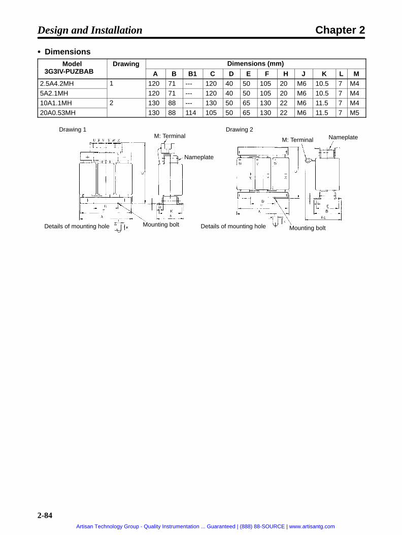
2-84
DimensionsModel
3G3IV PUZBABDrawing Dimensions (mm)
3G3IV-PUZBAB
gA B B1 C D E F H J K L M
2.5A4.2MH 1 120 71 --- 120 40 50 105 20 M6 10.5 7 M45A2.1MH 120 71 --- 120 40 50 105 20 M6 10.5 7 M410A1.1MH 2 130 88 --- 130 50 65 130 22 M6 11.5 7 M420A0.53MH 130 88 114 105 50 65 130 22 M6 11.5 7 M5
Drawing 1 Drawing 2M: Terminal
Nameplate
Details of mounting hole Mounting bolt Mounting boltDetails of mounting hole
NameplateM: Terminal
Design and Installation Chapter 2
Artisan Technology Group - Quality Instrumentation ... Guaranteed | (888) 88-SOURCE | www.artisantg.com

2-85
2-2-6 Peripheral Device Connection Examples Connecting FND-X06 to X25 Position Drivers to Peripheral Devices
Connect an external Regen-erative Resistor if the regen-eration capacity in the PositionDriver is not sufficient.
The external RegenerativeResistor can heat to 120°C.Install the Resistor so that heating willnot cause adverse affects.
Remove the short bar from between JP1and JP2 when connecting an external Re-generative Resistor.
R
S A
B
C
CN2 (M.SEN)
NFB
PL
1MC
X
M
ON
1MC X
CN1 (CONT)
24 VDC
OFF
CN1(CONT)
28 ALM
R S Single-phase, 200/240 VAC, 50/60 Hz (FND-XH)Single-phase, 100/115 VAC, 50/60 Hz (FND-XL)
Main-circuitpower supply Main-circuit connector
Surge killer
Servo error display
OMNUC FND-X-seriesPosition Driver
OMNUC U-series Power Cable30 to 750 W
R88A-CAUSR88A-CAUB
1 to 2 kWR88A-CAUBSR88A-CAUBB
EC DirectivesR88A-CAU001R88A-CAU01B
OMNUC H-series Power CableR88A-CAHSR88A-CAHB
OMNUC U/H/M-seriesAC Servomotor
Ground (to 100 Ωor less)
OMNUC U-series Encoder Cable30 to 750 W
R88A-CRUC (Incremental)R88A-CSUC (Absolute)
1 to 2 kW (Incremental and Absolute)R88A-CRUBN
EC DirectivesR88A-CRUDC (Incremental)R88A-CSUDC (Absolute)
OMNUC H-series Encoder CableR88A-CRHC + R88A-CRH0R5T
OMNUC M-series Resolver CableR88A-CRMN + R88A-CRM0R5T
X
1MC
19 OGND
TB
TB
(See note)
Regenerative Resistor100W: R88A-RR20030 200 W: R88A-RR40030
DIO Position Drivers: FND-CCXS General-purpose Control CableCompoBus/S Position Drivers : Communications Cable(SCA1-4F10 Flat Cable or commercially available VCTFcable (VCTF JIS C3306 2-core 0.75mm2))
User’scontroldevice
P
JP1
TB
JP2
R
Short bar
Protectivelyseparated
Note When using the CompoBus/S Position Drivers, create the same sequence using the ALM bit.
Design and Installation Chapter 2
Artisan Technology Group - Quality Instrumentation ... Guaranteed | (888) 88-SOURCE | www.artisantg.com
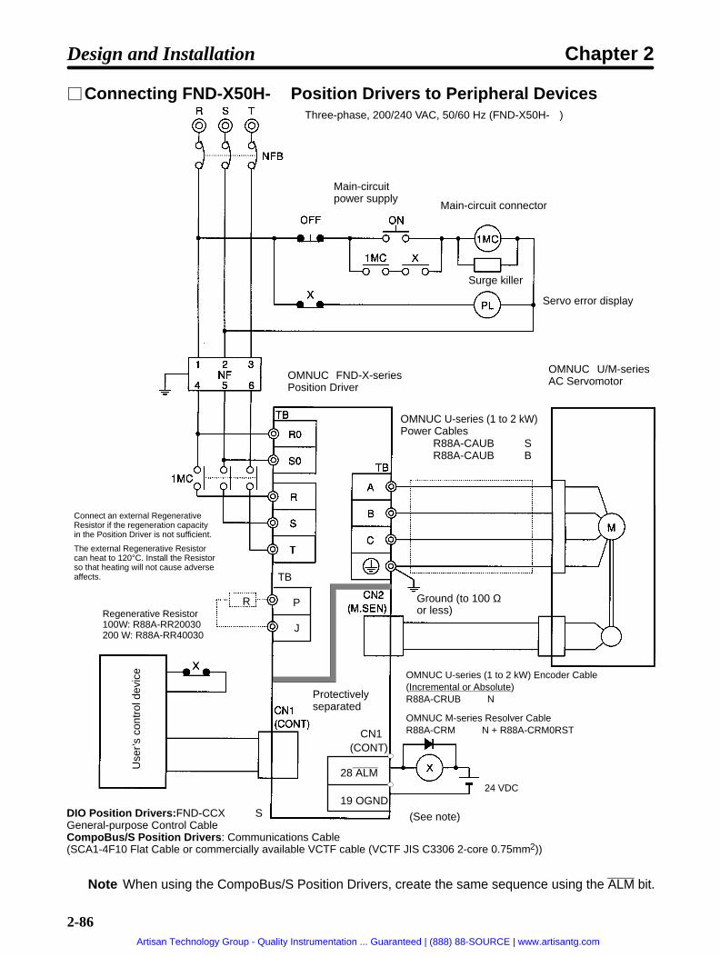
2-86
Connecting FND-X50H- Position Drivers to Peripheral Devices
24 VDC
Main-circuitpower supply
Main-circuit connector
Surge killer
Servo error display
OMNUC FND-X-seriesPosition Driver
OMNUC U-series (1 to 2 kW)Power Cables
OMNUC U/M-seriesAC Servomotor
Ground (to 100 Ωor less)
Use
r’s
cont
rol d
evic
e
DIO Position Drivers: FND-CCXS General-purpose Control CableCompoBus/S Position Drivers : Communications Cable(SCA1-4F10 Flat Cable or commercially available VCTF cable (VCTF JIS C3306 2-core 0.75mm2))
R88A-CAUBSR88A-CAUBB
(See note)
Three-phase, 200/240 VAC, 50/60 Hz (FND-X50H-)
Protectivelyseparated
Regenerative Resistor100W: R88A-RR20030 200 W: R88A-RR40030
Connect an external RegenerativeResistor if the regeneration capacityin the Position Driver is not sufficient.
The external Regenerative Resistorcan heat to 120°C. Install the Resistorso that heating will not cause adverseaffects.
19 OGND
28 ALM
P
J
TB
OMNUC U-series (1 to 2 kW) Encoder Cable (Incremental or Absolute)R88A-CRUBN
OMNUC M-series Resolver CableR88A-CRMN + R88A-CRM0RSTCN1
(CONT)
R
Note When using the CompoBus/S Position Drivers, create the same sequence using the ALM bit.
Design and Installation Chapter 2
Artisan Technology Group - Quality Instrumentation ... Guaranteed | (888) 88-SOURCE | www.artisantg.com

2-87
2-2-7 Battery Wiring and Encoder Setup for Absolute EncoderWhen using a U-series Servomotor with an absolute encoder, connect a lithium battery to the BAT con-nector (C6) so that the position data will be retained when the power supply is turned OFF. This sectionexplains how to wire and replace the battery, and how to set up the absolute encoder.
Use one of the following methods.
1. Obtain an OTS-BAT01 Battery with Connector and Cable.
2. Obtain a lithium battery and connector and prepare the battery so that it can be connected to CN6.(The C500-BAT08 Battery cannot be connected directly. The connector must be replaced with arecommend connector and the battery must be prepared for connection.)
The rest of this section describes the battery wiring and replacement methods and the absolute encodersetup.
BAT Connector (CN6)Driver rear panel
BAT connector(CN6)
Pin arrangement
Battery Wiring
Lithium battery
Pin No. Symbol Name and contents1 FG Frame ground
2 BAT Backup battery + input: connects 2.8 to 4.5-VDC battery.
3 BATGND Backup battery – input: ground for backup battery.
Design and Installation Chapter 2
Artisan Technology Group - Quality Instrumentation ... Guaranteed | (888) 88-SOURCE | www.artisantg.com

2-88
Lithium Battery (Recommended Products)With an absolute encoder, a battery must be used in order to retain position data when the power isturned OFF.
Maker Model Voltage Electrical capacity Estimated service lifeToshiba ER6V 3.6 V 2,000 mAh Approx. 10 years
OMRON (made byHitachi Maxell)
3G2A9-BAT08 3.6 V 1,650 mAh Approx. 7 years
Note 1. When power is turned OFF internally at the Position Driver, the battery voltage is not moni-tored. Be careful not to let the voltage drop below 2.8 V. If necessary, install a battery voltage-drop detection circuit or a monitor in the system.
Note 2. Use one battery for one Position Driver. (The estimated battery service life is calculated basedon this condition.)
Note 3. The Toshiba lithium battery does not have a connector for BAT connections. It is necessary toseparately purchase and attach a connector for BAT connections.
Replacing the BatteryThe following method can be used to replace the battery while retaining the absolute encoder’s rotationdata.
1. Turn ON the Position Driver’s power supply and leave it ON for three minutes. This will charge thecapacitor in the encoder.
2. Turn OFF the Position Driver’s power supply and leave it OFF while replacing the battery. Connectthe battery between pins 2 and 3 of the Position Driver’s BAT connector (CN6).
Note 1. After step 1 above has been implemented, the encoder will operate normally even with thebattery removed for up to two days (at 0°C to 40°C).
Note 2. While replacing the battery, be careful not to short-circuit the plus and minus terminals.
Note 3. When disconnecting the lead wires, disconnect the plus and minus terminals separately. Dis-connecting them at the same time can cause them to short-circuit and create sparks.
Note 4. Be sure to use the prescribed method for disposing of used batteries. In particular, do not un-der any circumstances dispose of them in a fire. Doing so may cause them to explode.
Setting up the Absolute EncoderSetup is required to set the amount of machine rotation to zero for trial operation of the Servomotor orwhen the absolute encoder has been left disconnected from the battery for more than two days. (This isbecause the voltage of the capacitor inside the absolute encoder will drop if a battery is left unconnectedfor more than two days, possibly interfering with the proper operation of internal elements.)
Design and Installation Chapter 2
Artisan Technology Group - Quality Instrumentation ... Guaranteed | (888) 88-SOURCE | www.artisantg.com

2-89
Setup MethodPerform the following procedure carefully. Mistakes may lead to errors in the setup.
1. Wire the Position Driver, Servomotor, and encoder correctly if they are not already wired correctly.
2. Connect the battery.
3. Turn ON power to the Position Driver.
4. Leave the power ON for three minutes.
Note An alarm may be generated, but it can be cleared with the following procedure.
5. Perform the following steps for 30-W to 750-W models.
a) Turn OFF the power to the Position Driver.
b) Remove the encoder connector.
c) Reset the data by shorting between encoder connector terminals 13 and 14 (on the motor side)for one or two seconds. (See the following diagram.)
Models conforming to UL/cUL Models conformingto EC Directives
1-kW/2-kW models
6. Perform the following steps for 1-kW to 2-kW models.
a) Turn OFF the power to the Position Driver.
b) Remove the encoder connector.
c) Reset the data by shorting between encoder connector terminals R and S (on the motor side) fortwo minutes. (See the above diagram.)
d) Remove the short between R and S.
e) Confirm that the voltage between R and S is 0.4 V or less. The S terminal is ground.
f) If the voltage is greater than 0.4 V, reconnect the terminals until the voltage drops to 0.4 V or less.
7. Restore the wiring to its original state.
8. Turn the power back ON to the Position Driver.
9. If no error occurs, the setup has been completed.
10. If an alarm (A.L41, 42 or 43) occurs, repeat this procedure from the beginning.
Design and Installation Chapter 2
Artisan Technology Group - Quality Instrumentation ... Guaranteed | (888) 88-SOURCE | www.artisantg.com

Chapter 3
Operation
3-1 Operational Procedure
3-2 Turning ON Power and Checking Displays
3-3 Using the Display Area
3-4 Setting Functions: User Parameters (H Parameters)
3-5 Position Control Settings (PTP Parameters)
3-6 Setting Positioning Data (PTP Data, Direct Input)
3-7 Operational Sequence
3-8 Trial Operation
3-9 Making Adjustments
3-10 Regenerative Energy Absorption
3
Artisan Technology Group - Quality Instrumentation ... Guaranteed | (888) 88-SOURCE | www.artisantg.com
3-2
3-1 Operational Procedure
After confirming that the system has been correctly installed and wired, make the initialsettings for the Position Driver. Then, set the position control functions according to theposition control methods. Any incorrect settings in the parameters could cause unexpected motor operation,creating an extremely dangerous situation. Use the procedures provided in this chapterto carefully set all parameters.
Startup Procedure
1. Mounting and installation
Install the Servomotor and Driver according to the installation conditions. Refer to 2-1 Installation.
2. Wiring and connections
Connect to power supply and peripheral devices. Refer to 2-2 Wiring.
3. Turning ON power supply
Before turning ON the power supply, check the necessary items. In order to make the initial settings,turn ON the applicable power supply. Refer to 3-2-1 Items to Check Before Turning ON Power.
4. Checking display status
Check by means of the displays to see whether there are any internal errors in the Driver. Refer to3-2-2 Turning ON Power and Confirming the Display.
5. Function settings
Set the user parameters for operation. Refer to 3-4 Setting Functions: User Parameters (H Parame-ters).
6. Position control settings
Set the PTP parameters according to the position control methods. Refer to 3-5 Position ControlSettings (PTP Parameters).
7. Position data settings
Set the data for executing positioning with PTP data or direct input. Refer to 3-6 Setting PositioningData (PTP Data, Direct Input).
8. Trial operation
Before performing trial operation, turn the power supply off and then back on so that any parametersthat have been set will be valid. Check to see whether protective functions such as emergency stopand operational limits are working reliably. Check operation at both low speed and high speed.Refer to 3-8 Trial Operation.
9. Adjustments
Execute auto-tuning. Manually adjust the gain as required. Refer to 3-9 Making Adjustments.
10. Operation
Operation can now begin. Should any trouble occur, refer to Chapter 4 Application.
Operation Chapter 3
Artisan Technology Group - Quality Instrumentation ... Guaranteed | (888) 88-SOURCE | www.artisantg.com

!
!
!
!
!
!
!
3-3
Operation and Adjustment PrecautionsCaution Confirm that no adverse effect will occur in the system before performing the test
operation. Not doing so may result in equipment damage.
Caution Check the newly set parameters for proper execution before actually running them.Not doing so may result in equipment damage.
Caution Do not make any extreme adjustments or setting changes. Doing so may result inunstable operation and injury.
Caution Separate the Servomotor from the machine, check for proper operation, and thenconnect to the machine. Not doing so may cause injury.
Caution When an alarm occurs, remove the cause, reset the alarm after confirming safety,and then resume operation. Not doing so may result in injury.
Caution Do not come close to the machine immediately after resetting momentary powerinterruption to avoid an unexpected restart. (Take appropriate measures to securesafety against an unexpected restart.) Doing so may result in injury.
Caution Do not use the built-in brake of the Servomotor for ordinary braking. Doing so mayresult in malfunction.
Operation Chapter 3
Artisan Technology Group - Quality Instrumentation ... Guaranteed | (888) 88-SOURCE | www.artisantg.com
3-4
3-2 Turning ON Power and Checking Displays
3-2-1 Items to Check Before Turning ON the Power
Checking Power Supply VoltageCheck to be sure that the power supply voltage is within the ranges shown below.
FND-X06H- /-X12H- /-X25H- (single-phase, 200-VAC specifications): Single-phase 200/240 VAC (170 to 264 V) 50/60 Hz
FND-X50H- (three-phase, 200-VAC specifications):Three-phase 200/240 VAC (170 to 264 V) 50/60 Hz
FND-X L- (single-phase, 100-VAC specifications):Single-phase 100/115 VAC (85 to 127 V) 50/60 Hz
Checking Terminal Block Wiring• Power supply inputs (models with single-phase inputs: R and S, models with three-phase inputs: R,
S, T, R0, S0) must be properly connected to the terminal block.
• The Servomotor’s red (A/U), white (B/V), and blue/black (C/W) power lines and the green ground
wire ( ) must be properly connected to the terminal block.
Checking the Servomotor Wiring• There should be no load on the Servomotor. (Do not connect to the mechanical system.)
• The power line connectors at the Servomotor must be securely connected.
Checking Encoder and Resolver Connectors Wiring• Encoder and resolver cables must be securely connected to the motor sensor connectors (CN2) at
the Driver.
• Encoder and resolver cables must be securely connected to the encoder/resolver connectors at theServomotor.
Checking Control Signal Connector Wiring• Be sure that the control signal connectors or the CompoBus/S terminals and external control signal
connectors are firmly connected.
• The RUN command must be OFF.
Operation Chapter 3
Artisan Technology Group - Quality Instrumentation ... Guaranteed | (888) 88-SOURCE | www.artisantg.com

3-5
3-2-2 Turning ON the Power and Checking the Display
Turning ON the PowerBefore turning ON the power supply, check carefully to confirm that it is safe.
Checking DisplaysWhen the power is turned ON, one of the codes shown below will be displayed.
Normal (motor speed display) Error (alarm display) Factory settings(parameter setting error)
0r 40.a.l 26.a.l
Note The alarm code (the number shown in the alarm display) changes depending on the contents ofthe error.
If the power is turned ON with the factory settings in place, a parameter setting error (A.L 26) will bedisplayed. This is because the applicable motor parameter (UP-02) factory setting is “0000.” Referringto the following tables and example procedure, set in UP-02 the model code for the motor that is to beused.
U Series (With Incremental Encoder)Motor model Capacity Code
R88M-U03030HA(VA) 30 W 1401
R88M-U05030HA(VA) 50 W 1402
R88M-U10030HA(VA) 100 W 1403
R88M-U20030HA(VA) 200 W 1404
R88M-U40030HA(VA) 400 W 1405
R88M-U75030HA(VA) 750 W 1406
R88M-U1K030H(V) 1 KW 1607
R88M-U1K530H(V) 1.5 kW 1608
R88M-U2K030H(V) 2 kW 1609
Note The motor code for R88M-U1K315H(V) is 160D.
U Series (With Absolute Encoder)Motor model Capacity Code
R88M-U03030TA(XA) 30 W 1501
R88M-U05030TA(XA) 50 W 1502
R88M-U10030TA(XA) 100 W 1503
R88M-U20030TA(XA) 200 W 1504
R88M-U40030TA(XA) 400 W 1505
R88M-U75030TA(XA) 750 W 1506
R88M-U1K030T(X) 1 KW 1507
R88M-U1K530T(X) 1.5 kW 1508
R88M-U2K030T(X) 2 kW 1509
Note The motor code for R88M-U1K315X is 1513.
Operation Chapter 3
Artisan Technology Group - Quality Instrumentation ... Guaranteed | (888) 88-SOURCE | www.artisantg.com

3-6
U-UE SeriesMotor model Capacity Code
R88M-UE10030H(V)-S1 100 W 1603
R88M-UE20030H(V)-S1 200 W 1604
R88M-UE40030H(V)-S1 400 W 1605
R88M-UE75030H(V)-S1 750 W 1606
H SeriesMotor model Capacity Code
R88M-H05030 50 W 1007
R88M-H10030 100 W 1008
R88M-H20030 200 W 1009
R88M-H30030 300 W 1010
R88M-H50030 500 W 1011
R88M-H75030 750 W 1012
R88M-H1K130 1100 W 1013
M Series (1,200 r/min)Motor model Capacity Code
R88M-M20012 200 W 0105
R88M-M40012 400 W 0106
R88M-M70012 700 W 0107
R88M-M1K112 1100 W 0108
R88M-M1K412 1400 W 0109
R88M-M1K812 1800 W 010A
M Series (2,000 r/min)Motor model Capacity Code
R88M-M20020 200 W 0205
R88M-M40020 400 W 0206
R88M-M70020 700 W 0207
R88M-M1K120 1100 W 0208
R88M-M1K820 1800 W 0217
R88M-M2K220 2200 W 0218
M Series (4,000 r/min)Motor model Capacity Code
R88M-M06040 60 W 0405
R88M-M12040 120 W 0406
R88M-M20040 200 W 0407
R88M-M40040 400 W 0408
R88M-M70040 700 W 0409
R88M-M1K140 1100 W 040A
R88M-M2K040 2000 W 040B
Operation Chapter 3
Artisan Technology Group - Quality Instrumentation ... Guaranteed | (888) 88-SOURCE | www.artisantg.com

3-7
Note U-UE-series (U-series, UE-type) and H-series Servomotors can only be used with Position Driversoftware version 4.01 (September 1997) or later. U-series 1 to 2-kW and M-series 1.1 to 2.2-kWServomotors can only be used with Position Driver software version 4.04 (April 1999) or later.
Example: Procedure for Setting Code 1403Display Key operation
a.l 26. Parameter setting error (A.L 26) displayed. (The “.” in the rightmost digit flashes.)
up01. Press the Mode Key twice to display the user parameters.
0000. Press the Increment Key three times to display the contents of UP-02 (applicablemotor).
0000. Press the Data Key and the Shift Key simultaneously to enable data to bechanged.
0003. Press the Increment Key three times to enter “3” for the rightmost digit.
0003. Press the Shift Key twice. The “100” digit (the third digit from the right) will flash.
0403. Press the Increment Key four times to enter “4” for the “100” digit.
1403. In the same way, press the Shift Key again so that the “1,000” digit (the leftmostdigit) flashes, and then press the Increment Key to enter “1” for that digit.
1403. Finally, press the Data Key to set the data.
Note After setting the parameters, turn OFF the power and check to be sure that the displays haveturned OFF before turning the power back ON again. (The values set for UP-02 will go into effectwhen the power is turned back ON.)
If the display is normal (motor speed display) after the power is turned ON, rotate the motor shaft byhand in both the forward and reverse directions and check to make sure that the positive and negativesigns in the display match the direction of rotation. If they do not match, check the encoder and resolvercables to make sure they are connected correctly.
Reverse rotation
Forward rotation
Display example r 3 8 Forward rotation
Reverse rotationr 2 5Flashing
If an error message (A.L ) is displayed when the power is turned ON, refer to Chapter 4 Applicationand take the necessary countermeasures.
Operation Chapter 3
Artisan Technology Group - Quality Instrumentation ... Guaranteed | (888) 88-SOURCE | www.artisantg.com
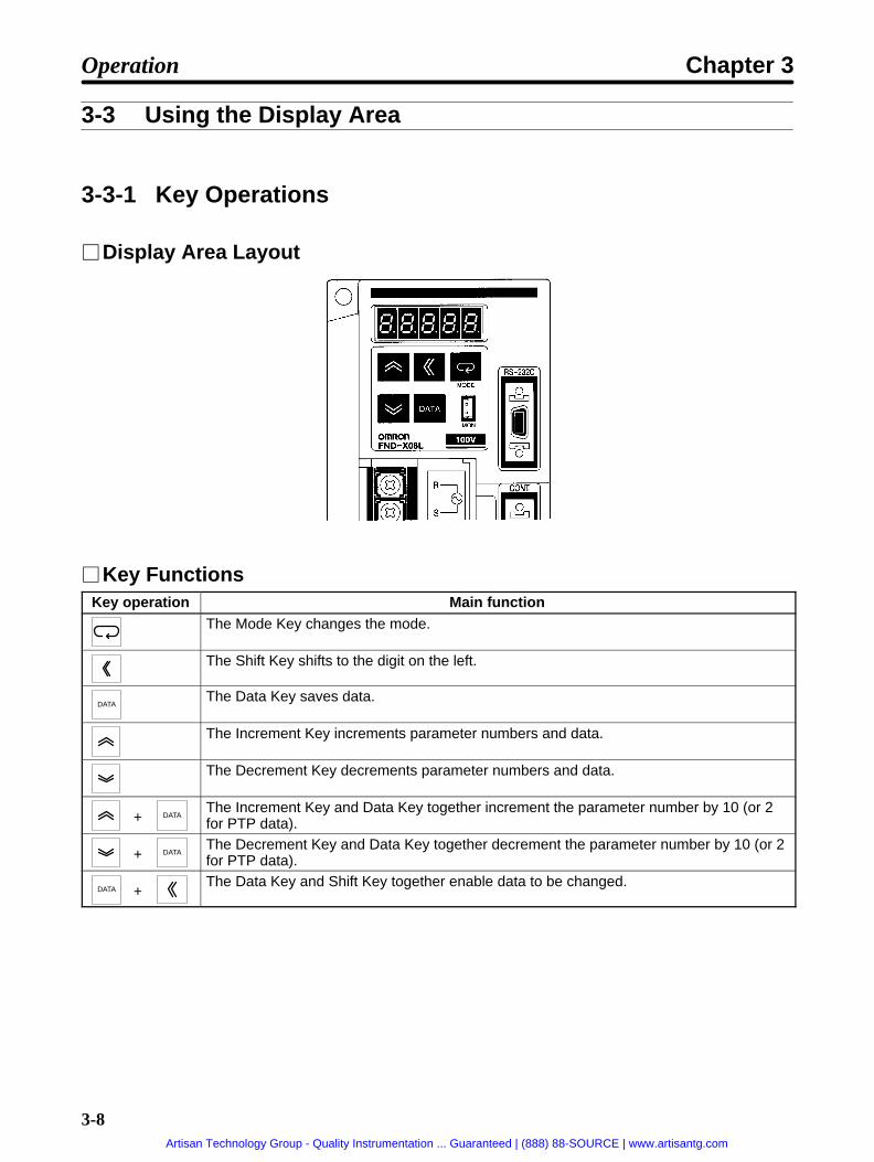
3-8
3-3 Using the Display Area
3-3-1 Key Operations
Display Area Layout
Key FunctionsKey operation Main function
The Mode Key changes the mode.
The Shift Key shifts to the digit on the left.
DATAThe Data Key saves data.
The Increment Key increments parameter numbers and data.
The Decrement Key decrements parameter numbers and data.
+ DATAThe Increment Key and Data Key together increment the parameter number by 10 (or 2for PTP data).
+ DATAThe Decrement Key and Data Key together decrement the parameter number by 10 (or 2for PTP data).
DATA +The Data Key and Shift Key together enable data to be changed.
Operation Chapter 3
Artisan Technology Group - Quality Instrumentation ... Guaranteed | (888) 88-SOURCE | www.artisantg.com

3-9
3-3-2 Modes and Mode Changes
ModesThe OMNUC FND-X Series has the following seven modes:
Mode FunctionMonitor Mode Monitors motor speed, present value, reference value, position deviation
value, machine speed, motor current, effective load factor, electronicthermal value, electrical angle, and regenerative absorption rate.
Check Mode Displays the I/O signal status, alarm details, alarm history, and softwareversion.
Adjustment Parameter Edit Mode Displays and sets the adjustment parameters.
User Parameter Edit Mode Displays and sets the user parameters and H parameters.
PTP Parameter Edit Mode Displays and sets the PTP parameters.
PTP Data Edit Mode Displays and sets the PTP data.
System Check Mode Used for motor test operation, output signal testing, and auto-tuning.
Changing ModesTo change modes, press the Mode Key. The System Check Mode and H parameter editing, however,require special operations.
Monitor Mode
Check Mode
Adjustment Parameter Edit Mode
User Parameter Edit Mode
PTP Parameter Edit Mode
(Press for at least 5 seconds)
System Check Mode
(Double-click)
H Parameter Edit
(Displayed only when UP-01 is 11 or 12.)
Powersupply ON
PTP Data Edit Mode
Operation Chapter 3
Artisan Technology Group - Quality Instrumentation ... Guaranteed | (888) 88-SOURCE | www.artisantg.com

3-10
3-3-3 Mode DetailsThe following diagram outlines the contents of each of the modes.
Monitor Mode
(Press for atleast 5 seconds.)
(Double-click)
System Check Mode
Check Mode
Motor speed
Present value
Regenerative absorption
Motor test operationOutput signal testAuto-tuning
Input signal displayAlarm displayAlarm history display
Adjustment Parameter Edit Mode AJ2 Speed loop proportional gainAJ3 Speed loop integral gainAJ4 Position loop gainAJ7 Interrupt gain suppressionAJ8 Feed forward gainAJ9 Current reference filter
User Parameter Edit Mode UP-01 Control modeUP-02 Motor code
UP-31 External regeneration resistance capacity
To monitormode
(Double-click)
H Parameter Edit HP-33 Load rate timeHP-46 In-position
PTP Parameter Edit Mode PP-01 Minimum Setting UnitPP-02 Pulse rate 1
PP-26 Selection signal output time
PTP Data Edit Mode Pd01H Point No. 1 Position data (leftmost)Pd01L Point No. 1 Position data (rightmost)Pd01F Point No. 1 Speed dataPd01A Point No. 1 Acceleration/deceleration selectionPd01r Point No. 1 Operation mode selection
Pd64H Point No. 64 Position data (leftmost)Pd64L Point No. 64 Position data (rightmost)Pd64F Point No. 64 Speed dataPd64A Point No. 64 Acceleration/deceleration selectionPd64r Point No. 64 Operation mode selection
DATA+ +
DATA+ +
Software version display
Referto 4-1.
Referto3-8-2and3-9.
Referto 4-2.
Referto 3-9.
Referto 3-4.
Referto 3-4.
Referto 3-5.
Referto 3-6.
Operation Chapter 3
Artisan Technology Group - Quality Instrumentation ... Guaranteed | (888) 88-SOURCE | www.artisantg.com

3-11
3-3-4 CompoBus/S Communications Display and Setting Panel
Layout of Display and Setting Panel
Rotary SwitchThe rotary switch is used for setting the node address. Each FND-X Position Driver occupies two con-secutive node addresses, set for IN and OUT respectively by the switch. The OUT Slave Area is allo-cated to the FND-X Position Driver’s input area, and the IN Slave Area is allocated to the FND-X Posi-tion Driver’s output area. The node addresses are allocated by the switch settings as follows:
Switch setting Output signals Input signals0/1 IN Slave 0, IN Slave 1 OUT Slave 0, OUT Slave 1
2/3 IN Slave 2, IN Slave 3 OUT Slave 2, OUT Slave 3
4/5 IN Slave 4, IN Slave 5 OUT Slave 4, OUT Slave 5
6/7 IN Slave 6, IN Slave 7 OUT Slave 6, OUT Slave 7
8/9 IN Slave 8, IN Slave 9 OUT Slave 8, OUT Slave 9
A/B IN Slave 10, IN Slave 11 OUT Slave 10, OUT Slave 11
C/D IN Slave 12, IN Slave 13 OUT Slave 12, OUT Slave 13
E/F IN Slave 14, IN Slave 15 OUT Slave 14, OUT Slave 15
The procedure when the C200HW-SRM21 is used for the Master Unit is provided here as an example.
Example: Master Unit Unit Number set to 0, Position Driver Node Address set to 0When the Master Unit number is 0, the starting word for the CPU Bus Unit area of the ProgrammableController that is allocated to the Programmable Controller will be set to word 100. Also, when the nodeaddress of the Position Driver is set to 0, the Slave areas of IN Slave 0 and 1 and OUT Slave 0 and 1 willbe allocated to the Position Driver. The control I/Os of the Position Driver are allocated to the Special I/OUnit area of the Programmable Controller as shown in the following tables.
Operation Chapter 3
Artisan Technology Group - Quality Instrumentation ... Guaranteed | (888) 88-SOURCE | www.artisantg.com

3-12
Word 100OUT Slave 1
Bit Signal name Signal allocation15 P. IN7 OUT15
14 P. IN6 OUT14
13 P. IN5 OUT13
12 P. IN4 OUT12
11 P. IN3 OUT11
10 P. IN2 OUT10
9 P. IN1 OUT9
8 P. IN0 OUT8
OUT Slave 0
Bit Signal name Signal allocation7 STOP OUT7
6 TEACH OUT6
5 –JOG OUT5
4 +JOG OUT4
3 SEARCH OUT3
2 RESET OUT2
1 START OUT1
0 RUN OUT0
Word 108IN Slave 1
Bit Signal name Signal allocation15 --- IN15
14 P. OUT6 IN14
13 P. OUT5 IN13
12 P. OUT4 IN12
11 P. OUT3 IN11
10 P. OUT2 IN10
9 P. OUT1 IN9
8 P. OUT0 IN8
IN Slave 0
Bit Signal name Signal allocation7 ALM IN7
6 INP IN6
5 RUNON IN5
4 T.COM IN4
3 ORGSTP IN3
2 S.COM IN2
1 READY IN1
0 BO IN0
Note 1. When using the CQM1-SRM21 as the Master Unit, be sure to set the number of points allo-cated to one node address to 8-point mode. If used in 4-point mode, an area overlap error willbe occur.
Note 2. For details regarding Master Unit word allocation, refer to the Master Unit operation manual.
CompoBus/S Communication Status IndicatorsIndicator Name Color Status Meaning
PWR Power supply Green Lit The power is turned ON.y
Not lit The power is turned OFF.COMM Communicating Yellow Lit Communications are being executed nor-
mally.Not lit There is a communications error or com-
munications are being awaited.ERR Communications error Red Lit A communications error has occurred.
Not lit Communications are being executed nor-mally or communications are beingawaited.
Note For details on diagnosis using the communication status indicators, refer to 4-4-3 CompoBus/S-type Position Driver Protective and Diagnostic Functions.
Operation Chapter 3
Artisan Technology Group - Quality Instrumentation ... Guaranteed | (888) 88-SOURCE | www.artisantg.com

3-13
3-4 Setting Functions: User Parameters (H Parameters)
User parameters and H parameters are parameters for selecting the control mode,applicable motor, and so on, which are required for system startup. Match the settings tothe system being used.Some of the user parameters go into effect when the power has been turned OFF andthen back ON again. (Check to be sure that the display has turned OFF.) Those userparameters that need to have the power turned OFF and ON again are indicated in thetables in 3-4-2 User Parameter and H Parameter Tables.Use the following procedure to set the user parameters:
Go to the User Parameter Edit Mode. Mode Key. . . . . . . .
Display the pertinent parameter number. Increment Key, Decrement Key,. . . . . Increment Key +Data Key, Decre-ment Key + Data Key
Display the parameter contents (data). Increment Key. . . . . . .
Enable the data change. Data Key + Shift Key. . . . . . . . . . . . . . . . . . .
Change the data. Increment Key, Decrement Key,. . . . . . . . . . . . . . . . . . . . . . . . . Shift Key
Save the data in memory. Data Key. . . . . . . . . . . . . . . . . .
3-4-1 Setting User Parameters and H Parameters
Setting User ParametersUse the following procedure to set the user parameters.
1. Press the Mode Key to go to the Users Parameter Edit Mode (UP-01).
2. Use the Up and Decrement Keys to display the parameter number (UP- ) desired.
3. Press the Increment Key to display the parameter data.
4. Press the Data Key and Shift Key simultaneously to enable a data change. The rightmost digit willflash.
5. Use the Up and Decrement Keys to change the data. The flashing numeral can be changed. Tomove to the next digit, press the Shift Key.
6. Press the Data Key to save the changed data in memory.
Operation Chapter 3
Artisan Technology Group - Quality Instrumentation ... Guaranteed | (888) 88-SOURCE | www.artisantg.com

3-14
User Parameters Display Example
Parameter number (UP-01) display
Data display (UP-01 contents)
Parameter number (UP-02) display
Data display (UP-02 contents)
Parameter number (UP-03) display
Data display (UP-03 contents)
Rightmost digitflashes.
Setting H ParametersUse the following procedure to set the H parameters.
1. Press the Mode Key to go to the Users Parameter Edit Mode (UP-01).
2. Press the Increment Key, Decrement Key, and Shift Key simultaneously to display H parameterHP-33.
3. Use the Up and Decrement Keys to display the parameter number (HP- ) desired.
4. Press the Increment Key to display the parameter data.
5. Press the Data Key and Shift Key simultaneously to enable a data change. The rightmost digit willflash.
6. Use the Up and Decrement Keys to change the data. The flashing numeral can be changed. Tomove to the next digit, press the Shift Key.
7. Press the Data Key to save the changed data in memory.
8. Double-click the Mode Key to go from H Parameter Edit to the Monitor Mode.
H Parameters Display Example
Parameter number (HP-33) display
Data display (HP-33 contents) Rightmost digitflashes.
User parameter display
Parameter number (HP-46) display
Data display (HP-46 contents)
Operation Chapter 3
Artisan Technology Group - Quality Instrumentation ... Guaranteed | (888) 88-SOURCE | www.artisantg.com

3-15
3-4-2 User Parameter and H Parameter Tables
The following tables list the user parameters (UP-01 to UP-29) and H parameters (HP-33 and HP-46).
User ParametersNo.UP-
Name Min. unit Settingrange
Factorysetting
Explanation Re-powerrequired?
01 Control mode --- 00 toFF
11 Specifies position control mode:11: Point positioning (PTP)12: Point positioning (feeder)13: Direct positioning (PTP)14: Direct positioning (feeder)
Yes
02 Motor code --- 0000 toFFFF
0000 Motor model code Yes
03 Resolver cablelength
1 m 1 to120
5 Sets the resolver cable length forwhen M-series motor is used. (Validonly for M-series motors.)
No
07 In-positionwidth
1 pulse 1 to32,767
3 Outputs positioning completed sig-nal (INP) according to number ofmotor sensor pulses set as posi-tioning deviation.
OMNUC U Series (30 to 750 W)with incremental encoder:8,192 pulses/rotationOMNUC U Series (30 to 650 W)with absolute encoder:4,096 pulses/rotationOMNUC U Series (1 to 2 kW) withincremental encoder:16,384 pulses/rotationOMNUC U Series (1 to 2 kW) withabsolute encoder: 32,768 pulses/rotationOMNUC U-UE Series:4,096 pulses/rotationOMNUC H Series: 8,000 pulses/rotationOMNUC M Series: 24,000 pulses/rotation
No
11 Current limit 0.1% 0.0 to100.0
100.0 Specifies rate based on maximummotor current as 100%.
No
14 S-curveacceleration/decelerationtime
0.01 s 0.00 to32.76
0.00 Sets the time until 90% of the targetspeed is obtained.
“0.00“ sets trapezoidal accelerationand deceleration.
No
16 Brake mode --- 0 to 3 0 0: Dynamic brake1: On-hold brake (stops in decel-
eration time)2: On-hold brake (stops after rota-
tion according to error counter’saccumulated number of pulses)
3: On-hold brake (free-runningstop)
Yes
Operation Chapter 3
Artisan Technology Group - Quality Instrumentation ... Guaranteed | (888) 88-SOURCE | www.artisantg.com

3-16
No.UP-
Re-powerrequired?
ExplanationFactorysetting
Settingrange
Min. unitName
25 Monitor output --- 000 to011
010 Specifies monitor output function.
0Positive voltage0: Not reversed1: Reversed
Speed/Current selection0: Current1: Speed
No
26 Motor rotationdirection
--- 0, 1 0 Specifies motor rotation direction.0: Forward rotation1: Reverse direction
No
28 Brake ONspeed
0.1% 0.0 to100.0
1.0 Specifies r/min to turn OFF breakoutput in on-hold brake mode.Specifies rate based on rated motorr/min as 100%.
* The brake may be damaged if theon-hold brake mode is selectedfor motors rotating at high speed.
No
29 Motor testspeed
1 r/min 1 to8,000
50 Specifies r/min for motors for test-ing.
* When testing a motor, make surethat the set value is less than therated motor r/min.
No
30 Externalregenerationresistancevalue
0.1 Ω 0.0 to100.0
0.0 Specifies the regenerationabsorption resistance value (Ω)
* Only valid for FND-X50H- .
* When using an OMRON ExternalRegeneration Resistor, set to 30.0(Ω).
Yes
31 Externalregenerationresistancecapacity
0.01 kW 0.00 to327.67
0.00 Specifies the regenerationabsorption resistance capacity(kW).
* Only valid for FND-X50H- .
Yes
H Parameters (HP-33, HP-46)No.HP-
Name Min.unit
Settingrange
Factorysetting
Explanation Re-powerrequired?
33 Load rate time 1 s 1 to 60 30 Specifies interval for effective loadfactor calculation to value obtainedfrom machine cycle time multipliedby an integer.
No
46 In-position timer 3.2 ms 3.2 to320.0
3.2 Specifies minimum positioningcompletion ON time and minimumready signal OFF time.
No
Operation Chapter 3
Artisan Technology Group - Quality Instrumentation ... Guaranteed | (888) 88-SOURCE | www.artisantg.com
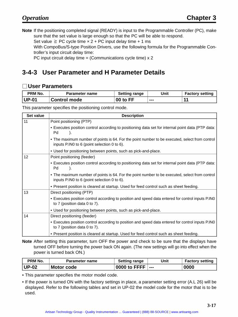
3-17
Note If the positioning completed signal (READY) is input to the Programmable Controller (PC), makesure that the set value is large enough so that the PC will be able to respond.Set value PC cycle time × 2 + PC input delay time + 1 msWith CompoBus/S-type Position Drivers, use the following formula for the Programmable Con-troller’s input circuit delay time:PC input circuit delay time = (Communications cycle time) x 2
3-4-3 User Parameter and H Parameter Details
User ParametersPRM No. Parameter name Setting range Unit Factory setting
UP-01 Control mode 00 to FF --- 11
This parameter specifies the positioning control mode.
Set value Description11 Point positioning (PTP)
• Executes position control according to positioning data set for internal point data (PTP data:Pd ).
• The maximum number of points is 64. For the point number to be executed, select from controlinputs P.IN0 to 6 (point selection 0 to 6).
• Used for positioning between points, such as pick-and-place.
12 Point positioning (feeder)
• Executes position control according to positioning data set for internal point data (PTP data:Pd ).
• The maximum number of points is 64. For the point number to be executed, select from controlinputs P.IN0 to 6 (point selection 0 to 6).
• Present position is cleared at startup. Used for feed control such as sheet feeding.
13 Direct positioning (PTP)
• Executes position control according to position and speed data entered for control inputs P.IN0to 7 (position data 0 to 7).
• Used for positioning between points, such as pick-and-place.14 Direct positioning (feeder)
• Executes position control according to position and speed data entered for control inputs P.IN0to 7 (position data 0 to 7).
• Present position is cleared at startup. Used for feed control such as sheet feeding.
Note After setting this parameter, turn OFF the power and check to be sure that the displays haveturned OFF before turning the power back ON again. (The new settings will go into effect when thepower is turned back ON.)
PRM No. Parameter name Setting range Unit Factory setting
UP-02 Motor code 0000 to FFFF --- 0000
• This parameter specifies the motor model code.
• If the power is turned ON with the factory settings in place, a parameter setting error (A.L 26) will bedisplayed. Refer to the following tables and set in UP-02 the model code for the motor that is to beused.
Operation Chapter 3
Artisan Technology Group - Quality Instrumentation ... Guaranteed | (888) 88-SOURCE | www.artisantg.com
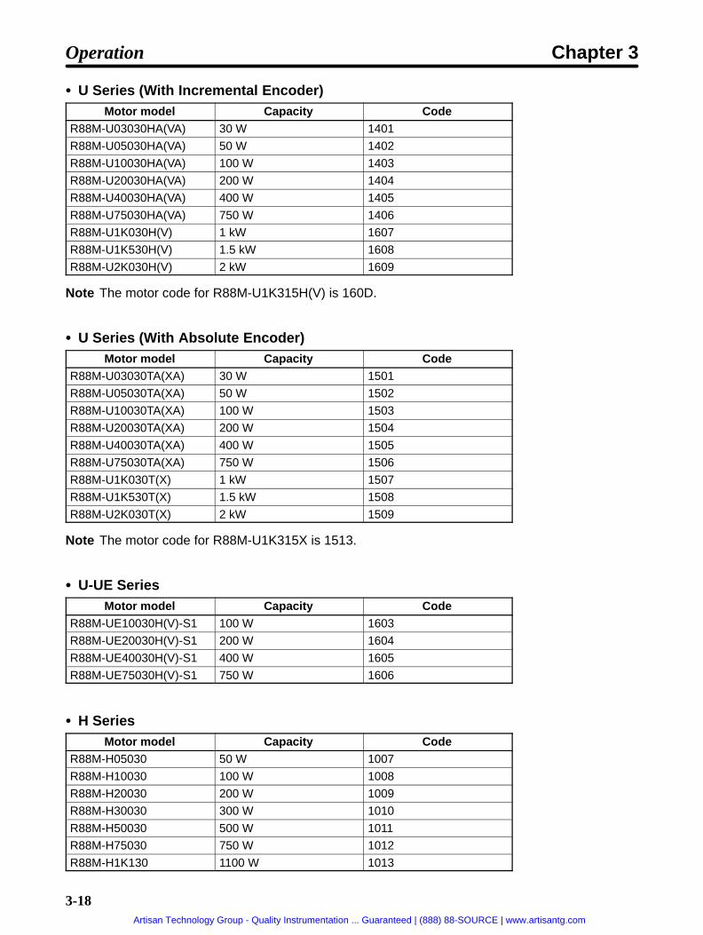
3-18
U Series (With Incremental Encoder)Motor model Capacity Code
R88M-U03030HA(VA) 30 W 1401
R88M-U05030HA(VA) 50 W 1402
R88M-U10030HA(VA) 100 W 1403
R88M-U20030HA(VA) 200 W 1404
R88M-U40030HA(VA) 400 W 1405
R88M-U75030HA(VA) 750 W 1406
R88M-U1K030H(V) 1 kW 1607
R88M-U1K530H(V) 1.5 kW 1608
R88M-U2K030H(V) 2 kW 1609
Note The motor code for R88M-U1K315H(V) is 160D.
U Series (With Absolute Encoder)Motor model Capacity Code
R88M-U03030TA(XA) 30 W 1501
R88M-U05030TA(XA) 50 W 1502
R88M-U10030TA(XA) 100 W 1503
R88M-U20030TA(XA) 200 W 1504
R88M-U40030TA(XA) 400 W 1505
R88M-U75030TA(XA) 750 W 1506
R88M-U1K030T(X) 1 kW 1507
R88M-U1K530T(X) 1.5 kW 1508
R88M-U2K030T(X) 2 kW 1509
Note The motor code for R88M-U1K315X is 1513.
U-UE SeriesMotor model Capacity Code
R88M-UE10030H(V)-S1 100 W 1603
R88M-UE20030H(V)-S1 200 W 1604
R88M-UE40030H(V)-S1 400 W 1605
R88M-UE75030H(V)-S1 750 W 1606
H SeriesMotor model Capacity Code
R88M-H05030 50 W 1007
R88M-H10030 100 W 1008
R88M-H20030 200 W 1009
R88M-H30030 300 W 1010
R88M-H50030 500 W 1011
R88M-H75030 750 W 1012
R88M-H1K130 1100 W 1013
Operation Chapter 3
Artisan Technology Group - Quality Instrumentation ... Guaranteed | (888) 88-SOURCE | www.artisantg.com

3-19
M Series (1,200 r/min)Motor model Capacity Code
R88M-M20012 200 W 0105
R88M-M40012 400 W 0106
R88M-M70012 700 W 0107
R88M-M1K112 1100 W 0108
R88M-M1K412 1400 W 0109
R88M-M1K812 1800 W 010A
M Series (2,000 r/min)Motor model Capacity Code
R88M-M20020 200 W 0205
R88M-M40020 400 W 0206
R88M-M70020 700 W 0207
R88M-M1K120 1100 W 0208
R88M-M1K820 1800 W 0217
RR88M-M2K220 2200 W 0218
M Series (4,000 r/min)Motor model Capacity Code
R88M-M06040 60 W 0405
R88M-M12040 120 W 0406
R88M-M20040 200 W 0407
R88M-M40040 400 W 0408
R88M-M70040 700 W 0409
R88M-M1K140 1100 W 040A
R88M-M2K040 2000 W 040B
Note After setting this parameter, turn OFF the power and check to be sure that the displays haveturned OFF before turning the power back ON again. (The new setting will go into effect when thepower is turned back ON.)
PRM No. Parameter name Setting range Unit Factory setting
UP-03 Resolver cable length 1 to 120 m 5
• This parameter specifies the resolver cable length for when M-series AC Servomotors are connected.
• Be sure to make this setting correctly. If the set value differs from the actual cable length, the motor’storque will be reduced.
• This parameter is not valid for motors other than M-series AC Servomotors.
Operation Chapter 3
Artisan Technology Group - Quality Instrumentation ... Guaranteed | (888) 88-SOURCE | www.artisantg.com

3-20
PRM No. Parameter name Setting range Unit Factory setting
UP-07 In-position width 1 to 32,767 Pulse 3
• This parameter specifies, by the number of motor sensor pulses, the position deviation for outputtingthe positioning completed signal (INP).
• OMNUC U Series 30 to 750 W with incremental encoder: 8,192 pulses/rotationOMNUC U Series 30 to 750 W with absolute encoder: 4,096 pulses/rotationOMNUC U Series 1 to 2 kW with incremental encoder: 16,384 pulses/rotationOMNUC U Series 1 to 2 kW with absolute encoder: 32,768 pulses/rotationOMNUC U-UE Series with incremental encoder: 4,096 pulses/rotationOMNUC H Series with incremental encoder: 8,000 pulses/rotationOMNUC M Series with resolver: 24,000 pulses/rotation
(absolute precision: 0.18°; ambient temperature: 25°C)
• Match this setting to the mechanical precision.
PRM No. Parameter name Setting range Unit Factory setting
UP-11 Current limit value 0.0 to 100.0 % 100.0
• This parameter specifies the maximum current provided to the motor, with the motor’s momentarymaximum current as 100%.
• Use this parameter to limit the torque added to the mechanical system.
PRM No. Parameter name Setting range Unit Factory setting
UP-14 S-curve acceleration/de-celeration time
0.0 to 32.76 s 0.00
• This parameter specifies the S-curve (filter characteristic) for the acceleration/deceleration time(PP-20 to PP-23).
• Use this parameter to suppress the impact to the mechanical system during acceleration and decel-eration.
• If the acceleration/deceleration time is 0, this will become the time until 90% of the target speed isobtained.
• When this parameter is set to “0.00,” the S-shaped acceleration/deceleration will be invalidated and atrapezoidal curve will be employed according to the acceleration/deceleration time (PP-20 to PP-23).
PRM No. Parameter name Setting range Unit Factory setting
UP-16 Brake mode 0 to 3 --- 0
This parameter specifies the brake output (BO) function and the method for stopping the motor whenthe RUN command is OFF.
Set value Description0 Brake output: dynamic brake; stop method: free-running stop
1 Brake output: on-hold brake; stop method: stop in deceleration time during execution
2 Brake output: on-hold brake; stop method: stop after rotation according to error counter’saccumulated number of pulses
3 Brake output: on-hold brake; stop method: free-running stop
Note After setting this parameter, turn OFF the power and check to be sure that the displays haveturned OFF before turning the power back ON again. (The new setting will go into effect when thepower is turned back ON.)
Operation Chapter 3
Artisan Technology Group - Quality Instrumentation ... Guaranteed | (888) 88-SOURCE | www.artisantg.com

!
3-21
PRM No. Parameter name Setting range Unit Factory setting
UP-25 Monitor output 000 to 011 --- 010
This parameter specifies the analog monitor output data and the output polarity.
Set value Description000 Current monitor output; output not reversed (positive voltage for forward torque)
001 Current monitor output; output reversed (negative voltage for forward torque)
010 Speed monitor output; output not reversed (positive voltage for forward motor rotation)
011 Speed monitor output; output reversed (negative voltage for forward motor rotation)
PRM No. Parameter name Setting range Unit Factory setting
UP-26 Motor rotation direction 0, 1 --- 0
This parameter specifies the direction of motor rotation.
Set value Description0 Rotation in forward direction with + direction command
1 Rotation in reverse direction with + direction command
Note “+direction” indicates the present value addition direction, and “– direction” indicates the presentvalue subtraction direction.
PRM No. Parameter name Setting range Unit Factory setting
UP-28 Brake ON speed 0.0 to 100.0 % 1.0
• When the on-hold brake (1, 2, 3) is set for the brake mode (UP-16), this parameter specifies the r/minfor turning OFF the brake output (BO).
• Set the motor’s rated r/min as 100%.
Caution If the on-hold brake is operated during high-speed motor rotation it will cause dam-age to the brake.
PRM No. Parameter name Setting range Unit Factory setting
UP-29 Motor test speed 1 to 8,000 r/min 50
• This parameter specifies the r/min for motor test operation.
• Set the motor test r/min to a value no higher than than the motor’s rated r/min.
PRM No. Parameter name Setting range Unit Factory setting
UP-30 External regenerationresistance value
0.0 to 100.0 Ω 0.0
• When attaching an External Regeneration Resistor, this parameter specifies its resistance value (Ω).
• This parameter is used for calculating the regeneration absorption rate. (The regeneration absorptionrate is displayed in Monitor Mode.)
Note 1. This parameter is only valid for the FND-X50H- .
Note 2. When using an OMRON External Regeneration Resistor, set to 30.0 (Ω).
Note 3. After this parameter has been set, it will become valid when the power supply is turned OFF(check that the display has been cleared) and ON again.
Operation Chapter 3
Artisan Technology Group - Quality Instrumentation ... Guaranteed | (888) 88-SOURCE | www.artisantg.com

3-22
PRM No. Parameter name Setting range Unit Factory setting
UP-31 External regenerationresistance capacity
0.00 TO327.67
kW 0.00
• When attaching an External Regeneration Resistor, this parameter specifies its capacity (kW).
• This parameter is used for calculating the regeneration absorption rate. (The regeneration absorptionrate is displayed in Monitor Mode.)
Note 1. This parameter is only valid for the FND-X50H- .
Note 2. After this parameter has been set, it will become valid when the power supply is turned OFF(check that the display has been cleared) and ON again.
H ParametersPRM No. Parameter name Setting range Unit Factory setting
HP-33 Load rate time 1 to 60 s 30
• This parameter specifies the time interval for the effective load factor calculation.
• Set the integer multiple for the machine cycle time.
• The effective load factor is displayed in Monitor Mode.
PRM No. Parameter name Setting range Unit Factory setting
HP-46 In-position timer 3.2 to 320.0 ms 3.2
• This parameter specifies the minimum ON time for the positioning completed signal and the minimumOFF time for the ready signal.
• Be sure to set enough time so that the Programmable Controller (PC) will be able to respond when thepositioning completed signal and the ready signal are received by the PC.
Set value PC cycle time × 2 + PC input delay time + 1 ms
• When the Increment and Decrement Keys are pressed, the set value is changed in units of 3.2 ms. Thedigit to be set cannot be specified by pressing the Shift Key.
Operation Chapter 3
Artisan Technology Group - Quality Instrumentation ... Guaranteed | (888) 88-SOURCE | www.artisantg.com

3-23
3-5 Position Control Settings (PTP Parameters)
PTP parameters are the parameters required for setting position data such as the mini-mum setting unit, pulse rate, reference speed, and so on.Some of the user parameters go into effect when the power has been turned OFF andthen back ON again. Those user parameters are indicated in the tables in 3-5-2 PTPParameters (PP-01 to PP-26).
Go to the User Parameter Edit Mode. Mode Key. . . . . . . .
Display the pertinent parameter number. Increment Key, Decrement Key,. . . . . Increment Key +Data Key, Decre-ment Key + Data Key
Display the parameter contents (data). Increment Key. . . . . . .
Enable the data change. Data Key + Shift Key. . . . . . . . . . . . . . . . . . .
Change the data. Increment Key, Decrement Key,. . . . . . . . . . . . . . . . . . . . . . . . . Shift Key
Save the data in memory. Data Key. . . . . . . . . . . . . . . . . .
3-5-1 Setting PTP Parameters (PP-01 to PP-26)Use the following procedure to set the PTP parameters.
1. Press the Mode Key to go to the PTP Parameter Edit Mode (PP-01).
2. Use the Increment and Decrement Keys to display the parameter number (PP- ) desired.
3. Press the Increment Key to display the parameter data.
4. Press the Data Key and Shift Key simultaneously to enable a data change. The rightmost digit willflash.
5. Use the Increment and Decrement Keys to change the data. The flashing numeral can be changed.To move to the next digit, press the Shift Key.
6. Press the Data Key to save the changed data in memory.
Operation Chapter 3
Artisan Technology Group - Quality Instrumentation ... Guaranteed | (888) 88-SOURCE | www.artisantg.com

3-24
PTP Parameter Display Example
Parameter number (PP-01) display
Data display (PP-01 contents)
Parameter number (PP-02) display
Data display (PP-02 contents)
Parameter number (PP-03) display
Data display (PP-03 contents)
Rightmostdigit flashes.
3-5-2 PTP Parameters (PP-01 to PP-26)No.PP-
Name Min.unit
Settingrange
Factorysetting
Explanation Re-powerrequired?
01 Minimum settingunit
--- 0.0001to 1
0.0001 Specifies basic unit for movementand speed value setting and display.
Yes
02 Pulse rate 1(Rotation)
1 revo-lution
1 to32,767
1 Specifies PP-02 to n and PP-03 to x(Note: “n” is the number of motor
Yes
03 Pulse rate 2(Movement)
1 1 to32,767
10(Note: n is the number of motorrevolutions and “x” is machine axismovement.)
Yes
04 Minimum resolu-tion (leftmostdigits)
--- --- 0.0 Used to display machine axis move-ment per motor sensor pulse. Thisfactory-set value cannot be changed.
Yes
05 Minimum resolu-tion (rightmostdigits)
--- --- 0042
y g
Yes
06 Origin com-pensation (left-most digits)
1 pulse –9,999to9,999
0 Specifies number of motor sensorpulses for movement between originsearch completion position and
hi i i i
No
07 Origin com-pensation (right-most digits)
0 to9,999
0 machine axis origin.
* The value can be obtained by ori-gin teaching.
No
08 Compensation(leftmost digits)
(PP-01)(Seenote 1.)
0 to9,999
0 Specifies backlash compensation ifUP-01 is set to 11 or 13 in PTP con-trol mode.
No
09 Compensation(rightmost digits)
note 1.)0 to9,999
0trol mode.Specifies slip compensation if UP-01is set to 12 or 14 in feeder controlmode.
No
10 Forward soft-ware limit (left-most digits)
(PP-01)(Seenote 1.)
–9,999to9,999
9,999 Specifies software limit position inthe forward direction.
* The software limit overflow in the
No
11 Forward soft-ware limit (right-most digits)
)
0 to9,999
9,999The software limit overflow in thepositive direction will not bedetected if the value is set to9999,9999.
No
Operation Chapter 3
Artisan Technology Group - Quality Instrumentation ... Guaranteed | (888) 88-SOURCE | www.artisantg.com

3-25
No.PP-
Re-powerrequired?
ExplanationFactorysetting
Settingrange
Min.unit
Name
12 Reverse soft-ware limit (left-most digits)
(PP-01)(Seenote 1.)
–9,999to9,999
–9,999 Specifies software limit position inthe reverse direction.
* The software limit overflow in the
No
13 Reverse soft-ware limit (right-most digits)
)
0 to9,999
9,999The software limit overflow in thereverse direction will not bedetected if the value is set to–9999,9999.
No
14 Referencespeed (leftmostdigits)
1/s 0 to9,999
0 Specifies machine axis referencespeed per second.
No
15 Referencespeed (rightmostdigits)
0 to9,999
500 No
16 JOG speed 1% 1 to199
10 Specifies motor r/min in JOG opera-tion as override value based on ref-erence speed.
No
17 Origin searchhigh speed
1% 1 to199
10 Specifies origin proximity searchspeed in origin search operation asoverride value based on referencespeed. This value is used as axisspeed for origin compensation aswell.
* Set an appropriate value so thatthe origin proximity signal can bedetected accurately.
No
18 Origin searchlow speed
1% 1 to199
1 Specifies phase-Z search speed inorigin search operation as overridevalue based on reference speed.
* Set an appropriate value so thatthe speed will be 500 r/min maxi-mum.
No
19 Origin searchdirection
--- 0, 1 0 Specifies origin search direction.0: Forward direction1: Reverse direction
No
20 Accelerationtime 0
1 ms 0 to9,999
0 Specifies time spent in reaching ref-erence speed after system is inoperation.
* This value is used as accelerationtime for the Position Driver in originsearch operation, JOG operation,point positioning operation, anddirect positioning operation.
No
21 Accelerationtime 1
1 ms 0 to9,999
100 Specifies time spent in reaching ref-erence speed after system is inoperation.
* This value will be valid if the Posi-tion Driver is in point positioningoperation.
No
Operation Chapter 3
Artisan Technology Group - Quality Instrumentation ... Guaranteed | (888) 88-SOURCE | www.artisantg.com

3-26
No.PP-
Re-powerrequired?
ExplanationFactorysetting
Settingrange
Min.unit
Name
22 Decelerationtime 0
1 ms 0 to9,999
0 Specifies time spent in deceleratingreference speed to a stop.
* This value is used as decelerationtime for the Position Driver in originsearch operation, JOG operation,point positioning operation, anddirect positioning operation.
No
23 Decelerationtime 1
1 ms 0 to9,999
100 Specifies time spent in deceleratingreference speed to a stop.
* This value will be valid if the Posi-tion Driver is in point positioningoperation.
No
24 Decelerationstop mode
--- 0 to 2 1 Selects stop method with STOP sig-nal OFF.0: Free-running stop1: Deceleration stop2: Error counter reset stop
No
25 Alarm selection --- 00 to 11 11 Selects alarm processing method withlimit or soft limit detection.
Overrun0: Servo-lock stop1: Servo-free alarm
Soft limit0: Servo-lock stop1: Servo-lock alarm
No
26 Selection signaloutput time (Seenote 2.)
0.8 ms 0.8 to800.0
20.0 Specifies time during which P.OUT0to P.OUT4 signals are turned ON forselecting position data and speeddata for direct positioning.
No
Note 1. The minimum setting value varies with the value set in PP-01. The setting unit is used formachine axis movement and can be changed with the pulse rate setting.Setting unit examples:Linear movement: mm, cm, m, inch, yardRotating movement: degree, rad, revolutionOther movement: Pulse
Note 2. Be sure to set enough time so that the Programmable Controller (PC) will be able to respondwhen the position and speed data selections are received by the PC.Set value PC cycle time × 2 + PC input delay time + 1 msWith CompoBus/S-type Position Drivers, use the following formula for the ProgrammableController’s input circuit delay time:PC input circuit delay time = (Communications cycle time) x 2
Operation Chapter 3
Artisan Technology Group - Quality Instrumentation ... Guaranteed | (888) 88-SOURCE | www.artisantg.com
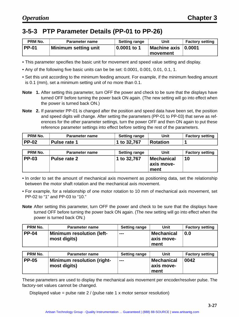
3-27
3-5-3 PTP Parameter Details (PP-01 to PP-26)PRM No. Parameter name Setting range Unit Factory setting
PP-01 Minimum setting unit 0.0001 to 1 Machine axismovement
0.0001
• This parameter specifies the basic unit for movement and speed value setting and display.
• Any of the following five basic units can be be set: 0.0001, 0.001, 0.01, 0.1, 1.
• Set this unit according to the minimum feeding amount. For example, if the minimum feeding amountis 0.1 (mm), set a minimum setting unit of no more than 0.1.
Note 1. After setting this parameter, turn OFF the power and check to be sure that the displays haveturned OFF before turning the power back ON again. (The new setting will go into effect whenthe power is turned back ON.)
Note 2. If parameter PP-01 is changed after the position and speed data have been set, the positionand speed digits will change. After setting the parameters (PP-01 to PP-03) that serve as ref-erences for the other parameter settings, turn the power OFF and then ON again to put thesereference parameter settings into effect before setting the rest of the parameters.
PRM No. Parameter name Setting range Unit Factory setting
PP-02 Pulse rate 1 1 to 32,767 Rotation 1
PRM No. Parameter name Setting range Unit Factory setting
PP-03 Pulse rate 2 1 to 32,767 Mechanicalaxis move-ment
10
• In order to set the amount of mechanical axis movement as positioning data, set the relationshipbetween the motor shaft rotation and the mechanical axis movement.
• For example, for a relationship of one motor rotation to 10 mm of mechanical axis movement, setPP-02 to “1” and PP-03 to “10.”
Note After setting this parameter, turn OFF the power and check to be sure that the displays haveturned OFF before turning the power back ON again. (The new setting will go into effect when thepower is turned back ON.)
PRM No. Parameter name Setting range Unit Factory setting
PP-04 Minimum resolution (left-most digits)
--- Mechanicalaxis move-ment
0.0
PRM No. Parameter name Setting range Unit Factory setting
PP-05 Minimum resolution (right-most digits)
--- Mechanicalaxis move-ment
0042
These parameters are used to display the mechanical axis movement per encoder/resolver pulse. Thefactory-set values cannot be changed.
Displayed value = pulse rate 2 / (pulse rate 1 x motor sensor resolution)
Operation Chapter 3
Artisan Technology Group - Quality Instrumentation ... Guaranteed | (888) 88-SOURCE | www.artisantg.com

3-28
Motor sensor resolution:
OMNUC U Series 30 to 750 W with incremental encoder: 8,192 pulses/rotationOMNUC U Series 30 to 750 W with absolute encoder: 4,096 pulses/rotationOMNUC U Series 1 to 2 kW with incremental encoder: 16,384 pulses/rotationOMNUC U Series 1 to 2 kW with absolute encoder: 32,768 pulses/rotationOMNUC U Series with absolute encoder: 4,096 pulses/rotationOMNUC U-UE Series with incremental encoder: 4,096 pulses/rotationOMNUC H Series with incremental encoder: 8,000 pulses/rotationOMNUC M Series with resolver: 24,000 pulses/rotation
Note The displayed value will be changed after PP-01 to PP-03 have been set and the power has beenturned OFF and back ON again.
PRM No. Parameter name Setting range Unit Factory setting
PP-06 Origin compensation (left-most digits)
–9,999 to9,999
Pulse 0
PRM No. Parameter name Setting range Unit Factory setting
PP-07 Origin compensation (right-most digits)
0 to 9,999 Pulse 0
• These parameters are used to set the mechanical origin to any position.
• Set the number of motor sensor pulses for movement between the origin search completion positionand the mechanical origin.
• When origin teaching is executed, the data is automatically written to these parameters and the teach-ing position becomes the origin.
• After these parameters have been set, the mechanical origin can be moved by executing an originsearch.
PRM No. Parameter name Setting range Unit Factory setting
PP-08 Compensation (leftmostdigits)
0 to 9,999 Mechanicalaxis move-ment
0
PRM No. Parameter name Setting range Unit Factory setting
PP-09 Compensation (rightmostdigits)
0 to 9,999 Mechanicalaxis move-ment
0
• These parameters specify the amount of mechanical axis movement for compensation during posi-tioning operations.
• The decimal point location is set by PP-01 (minimum setting unit).
• For PTP control (UP-01: 11 or 13), this compensation becomes backlash compensation; for feedercontrol (UP-01: 12 or 14), it becomes slip compensation.
Backlash Compensation• Set the amount of play (backlash) for a mechanical system such as gears or chains.
• When movement is in the reverse direction from that of the previous operation, stopping precision canbe improved by feeding an exact amount of compensation to absorb the backlash in the mechanicalsystem.
Operation Chapter 3
Artisan Technology Group - Quality Instrumentation ... Guaranteed | (888) 88-SOURCE | www.artisantg.com

3-29
• The following diagram provides an example of backlash compensation during operation.
Backlash compensation
Slip Compensation• Set slip compensation if slippage occurs in the mechanical system during feeding.
• Set these parameters to compensate for the amount of slippage that occurs when feeding for just theamount set for pulse rate 2. For example, if 10 mm is fed with PP-01 (minimum setting unit) set to 0.001and PP-03 (pulse rate 2) to 10 (mm), and if the slippage amount is 0.1 mm, then set PP-08 to 0 andPP-09 to 0.100.
• Compensating for just the amount of slippage that occurs during feeding absorbs the play from themechanical system and improves the stopping precision. Also, in order to match the mechanical axisspeed to the command value, the motor is speeded up for just the amount of slippage (within themotor’s maximum speed range).
• The following diagram provides an example of slip compensation during operation.
SpeedSlip compensation
Motor rotation speed with slip compensation
Motor rotation speed without slip compensation
Time
PRM No. Parameter name Setting range Unit Factory setting
PP-10 Positive software limit(leftmost digits)
–9,999 to9,999
Mechanicalaxis move-ment
9,999
PRM No. Parameter name Setting range Unit Factory setting
PP-11 Positive software limit(rightmost digits)
0 to 9,999 Mechanicalaxis move-ment
9,999
PRM No. Parameter name Setting range Unit Factory setting
PP-12 Negative software limit(leftmost digits)
–9,999 to9,999
Mechanicalaxis move-ment
–9,999
PRM No. Parameter name Setting range Unit Factory setting
PP-13 Negative software limit(rightmost digits)
0 to 9,999 Mechanicalaxis move-ment
9,999
Operation Chapter 3
Artisan Technology Group - Quality Instrumentation ... Guaranteed | (888) 88-SOURCE | www.artisantg.com

3-30
• These parameters set limits on mechanical system movement.
• The decimal point location is set by PP-01 (minimum setting unit).
• When a software limit is detected, the motor is placed in servo-lock and stopped. The alarm outputstatus at that time is determined by the PP-25 (alarm selection) setting.
• After the motor has been stopped as a result of a software limit having been detected, the motor willonly be able to be driven in the direction which will release it from the software limit. (If alarm A.L34 orA.L35 has been generated, the alarm must be reset before the motor can be driven.)
• If the maximum value is set for a given detection direction (e.g., 99,999,999 for the positive softwarelimit), then the software limit for that direction will be ignored and the alarm detection will not be acti-vated.
PRM No. Parameter name Setting range Unit Factory setting
PP-14 Reference speed (leftmostdigits)
0 to 9,999 Mechanicalaxis move-ment
0
PRM No. Parameter name Setting range Unit Factory setting
PP-15 Reference speed (right-most digits)
0 to 9,999 Mechanicalaxis move-ment
500
• These parameters specify the motor’s speed during positioning, as the amount of mechanical axismovement per second.
• The actual speed becomes the reference speed x the override. (The override value is set as PTPspeed data or by direct input.)
PRM No. Parameter name Setting range Unit Factory setting
PP-16 JOG speed 1 to 199 % 10
This parameter specifies the motor r/min in JOG operation (+JOG, –JOG) as an override value based on thereference speed as 100%.
Note Set the JOG speed at or below the motor’s maximum speed.
PRM No. Parameter name Setting range Unit Factory setting
PP-17 Origin search high speed 1 to 199 % 10
• This parameter specifies origin proximity signal search speed in origin search operation as an over-ride value based on the reference speed as 100%.
• The origin search high speed is also used as the speed during origin compensation
Note Set an appropriate value so that the origin proximity signal can be detected accurately.
PRM No. Parameter name Setting range Unit Factory setting
PP-18 Origin search low speed 1 to 199 % 1
In origin search operation, this parameter specifies the motor sensor’s Z-phase search speed after ori-gin proximity signal detection as an override value based on the reference speed as 100%.
Note Set an appropriate value so that the speed will be 500 r/min maximum.
PRM No. Parameter name Setting range Unit Factory setting
PP-19 Origin search direction 0, 1 --- 0
Operation Chapter 3
Artisan Technology Group - Quality Instrumentation ... Guaranteed | (888) 88-SOURCE | www.artisantg.com

3-31
This parameter specifies the direction for beginning an origin search operation.
Set value Description0 Begins origin search in the positive direction (incrementing the present value).
1 Begins origin search in the negative direction (decrementing the present value).
PRM No. Parameter name Setting range Unit Factory setting
PP-20 Acceleration time 0 0 to 9,999 ms 0
PRM No. Parameter name Setting range Unit Factory setting
PP-21 Acceleration time 1 0 to 9,999 ms 100
• These parameters specify the time from a stop until the reference speed is reached.
• The actual acceleration time can be obtained from the following formula:[(Target speed – present speed) / reference speed] x acceleration time
If S-curve acceleration time (UP-14) is set, the acceleration time will be lengthened.
• Acceleration time 0 is used as the acceleration time for origin search, JOG operation, and positioningby direct input.
• When positioning with PTP data, acceleration time 0 or 1 can be selected using the PTP data’s accel-eration/deceleration selection (Pd A).
PRM No. Parameter name Setting range Unit Factory setting
PP-22 Deceleration time 0 0 to 9,999 ms 0
PRM No. Parameter name Setting range Unit Factory setting
PP-23 Deceleration time 1 0 to 9,999 ms 100
• These parameters specify the time from the reference speed until the positioning is stopped.
• The actual deceleration time can be obtained from the following formula:[(Present speed – target speed) / reference speed] x deceleration time
• Deceleration time 0 is used as the deceleration time for origin search, JOG operation, and positioningby direct input.
• When positioning with PTP data, deceleration time 0 or 1 can be selected using the PTP data’s accel-eration/deceleration selection (Pd A).
Acceleration/Deceleration Operation
Speed
Reference speed(PP-14, PP-15)
Actual motor response (example)
Acceleration time Deceleration time
Time
Operation Chapter 3
Artisan Technology Group - Quality Instrumentation ... Guaranteed | (888) 88-SOURCE | www.artisantg.com

3-32
PRM No. Parameter name Setting range Unit Factory setting
PP-24 Deceleration stop mode 0, 1, 2 --- 1
This parameter selects the stop method for when the deceleration stop (STOP) signal is OFF.
Set value Description0 Free-running stop. (Servo OFF)
1 Stop in deceleration time specified by positioning data during operation. (Servo-lock afterstop)
2 Stop with error counter reset. (Servo-lock after stop)
Note With a free-running stop, after the STOP signal has turned ON operation can be re-started byturning the RUN command from OFF to ON.
Deceleration Stop Operation
Speed Deceleration stop (STOP) OFF (1) Free-running stop
(2) Stop in deceleration time
(3) Error counter reset stop(1)
(2)
(3)
Position
Note After the deceleration stop (STOP) signal turns OFF, there is a maximum delay of 1.6 ms beforethe stop processing begins.
PRM No. Parameter name Setting range Unit Factory setting
PP-25 Alarm selection 00 to 11 --- 11
This parameter specifies the alarm processing method for when limit detection (overrun) or softwarelimit detection occurs.
Set value Description0 Servo-lock stop when software limit is detected.
1 Alarm (A.L34, A.L35) and servo-lock stop when software limit is detected.
0 Servo-lock stop when limit is detected.
1 Alarm (A.L38) and servo-free stop when limit is detected.
PRM No. Parameter name Setting range Unit Factory setting
PP-26 Selection signal outputtime
0.8 to 800.0 ms 20.0
• This parameter specifies the time during which P.OUT0 to P.OUT4 signals are turned ON for selectingposition data and speed data for positioning by direct input.
Operation Chapter 3
Artisan Technology Group - Quality Instrumentation ... Guaranteed | (888) 88-SOURCE | www.artisantg.com

3-33
• Be sure to set enough time for the Programmable Controller (PC) to respond when the position andspeed data selections are received by the PC.Set value PC cycle time × 2 + PC input delay time + 1 msWith CompoBus/S-type Position Drivers, use the following formula for the Programmable Controller’sinput circuit delay time:PC input circuit delay time = (Communications cycle time) x 2
• When the Increment and Decrement Keys are pressed, the set value is changed in units of 0.8 ms. Thedigit to be set cannot be specified by pressing the Shift Key.
Operation Chapter 3
Artisan Technology Group - Quality Instrumentation ... Guaranteed | (888) 88-SOURCE | www.artisantg.com
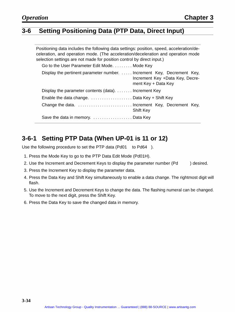
3-34
3-6 Setting Positioning Data (PTP Data, Direct Input)
Positioning data includes the following data settings: position, speed, acceleration/de-celeration, and operation mode. (The acceleration/deceleration and operation modeselection settings are not made for position control by direct input.)
Go to the User Parameter Edit Mode. Mode Key. . . . . . . .
Display the pertinent parameter number. Increment Key, Decrement Key,. . . . . Increment Key +Data Key, Decre-ment Key + Data Key
Display the parameter contents (data). Increment Key. . . . . . .
Enable the data change. Data Key + Shift Key. . . . . . . . . . . . . . . . . . .
Change the data. Increment Key, Decrement Key,. . . . . . . . . . . . . . . . . . . . . . . . . Shift Key
Save the data in memory. Data Key. . . . . . . . . . . . . . . . . .
3-6-1 Setting PTP Data (When UP-01 is 11 or 12)Use the following procedure to set the PTP data (Pd01 to Pd64 ).
1. Press the Mode Key to go to the PTP Data Edit Mode (Pd01H).
2. Use the Increment and Decrement Keys to display the parameter number (Pd ) desired.
3. Press the Increment Key to display the parameter data.
4. Press the Data Key and Shift Key simultaneously to enable a data change. The rightmost digit willflash.
5. Use the Increment and Decrement Keys to change the data. The flashing numeral can be changed.To move to the next digit, press the Shift Key.
6. Press the Data Key to save the changed data in memory.
Operation Chapter 3
Artisan Technology Group - Quality Instrumentation ... Guaranteed | (888) 88-SOURCE | www.artisantg.com

3-35
PTP Data Display Example
Parameter number (Pd01H) display
Data display (Pd01H contents)
Parameter number (Pd01L) display
Data display (Pd01L contents)
Parameter number (Pd01F) display
Data display (Pd01F contents)
Rightmost digit flashes.
Parameter number (Pd01A) display
Data display (Pd01A contents)
Parameter number (Pd01r) display
Data display (Pd01r contents)
Indicates incrementalvalue designation.
When PP-01 (minimum setting unit)is set to “0.0001,” zeroes followingthe decimal point are not displayed.
3-6-2 Setting Direct Input (When UP-01 is 13 or 14)• With direct input, the control inputs (P.IN0 to 7), position data (7 + 1/2 digits BCD), sign bit, I (incremen-
tal value) or A (absolute value) designation bit, and speed data (2 digits BCD) are taken in order.
• P.OUT0 to 4 (position selection 1 to 4, speed selection ) are output as timing signals for taking the data.
• Data is taken on the falling edge of the P.OUT signal. When setting data from the Programmable Con-troller, output the data between the time that P.OUT turns ON and turns OFF. The time that P.OUTstays ON for can be set by PP-26 (selection signal output time).
Operation Chapter 3
Artisan Technology Group - Quality Instrumentation ... Guaranteed | (888) 88-SOURCE | www.artisantg.com

3-36
Direct Input Positioning DataPosition data range: –39,999,999 to 39,999,999 (with incremental or absolute setting)
Speed data range: 0 to 99 (100%, 1 to 99%)
Inputsignal
Output signal
Name Position selection 1 Position selection 2 Position selection 3 Position selection 4 Speed selection
Position 7 2nd digit(P iti )
Bit 3 4th digit(P iti )
Bit 3 6th digit(P iti )
Bit 3 Position I/A bit 2nd digit(S d)
Bit 3
Position 6
d d g(Position) Bit 2
d g(Position) Bit 2
6 d g(Position) Bit 2 Position sign bit
d d g(Speed) Bit 2
Position 5 Bit 1 Bit 1 Bit 1 8th digit(P iti )
Bit 1 Bit 1
Position 4 Bit 0 Bit 0 Bit 0
8 d g(Position) Bit 0 Bit 0
Position 3 1st digit(P iti )
Bit 3 3rd digit(P iti )
Bit 3 5th digit(P iti )
Bit 3 7th digit(P iti )
Bit 3 1st digit(S d)
Bit 3
Position 2
s d g(Position) Bit 2
3 d d g(Position) Bit 2
5 d g(Position) Bit 2
d g(Position) Bit 2
s d g(Speed) Bit 2
Position 1 Bit 1 Bit 1 Bit 1 Bit 1 Bit 1
Position 0 Bit 0 Bit 0 Bit 0 Bit 0 Bit 0
Note 1. For example, when position selection 1 (P.OUT0) is ON, positions 0 to 7 (P.IN0 to 7) are takenas the position data’s first and second digits. (They are taken at the falling edge of P.OUT0.)
Note 2. The position sign bit specifies the position as “plus” when OFF (0), and “minus” when ON (1).
Note 3. The position data takes the value set by PP-01 (minimum setting unit).
Note 4. When the position I/A bit is OFF (0), I (incremental value) is set; when it is ON (1), A (absolutevalue) is set.
Note 5. Set the speed data with the reference speed (PP-14, PP-15) override value (%). If the speeddata is set to “0,” the override value will be 100%.
Note 6. With direct input, the acceleration/deceleration time is fixed at PP-20 (acceleration time 0)and PP-22 (deceleration time 0).
Direct Input Setting ExampleIn this example, positioning is moved at 250 mm/s to an absolute-value position of 1,000 mm, with themechanical system set for 10 mm of movement per motor rotation, a minimum feed amount of 1 µm, anda reference speed of 500 mm/s.
Parameter SettingsMinimum setting unit: PP-01 = 0.001 (minimum feed amount: 0.001 mm)Pulse rate: PP-02 = 1; PP-03 = 10 (10 mm of movement per motor rotation)Reference speed: PP-14 = 0; PP-15 = 500 (500 mm/s)
Operation Chapter 3
Artisan Technology Group - Quality Instrumentation ... Guaranteed | (888) 88-SOURCE | www.artisantg.com

3-37
Direct Input Data (Signal) Settings
Position data: “A + 01000000” (x 0.001 mm) = 81000000
Speed data: 50 (%) Position selection 1
Position selection 2
Position selection 3
Position selection 4
Input signal Output signal
Name Position selection 1 Position selection 2 Position selection 3 Position selection 4 Speed selection
Position 7 OFF 0 OFF 0 OFF 0 ON A 8 OFF 5
Position 6 OFF
0
OFF
0
OFF
0
OFF +
8
ON
5
Position 5 OFF OFF OFF OFF 0 OFF
Position 4 OFF OFF OFF OFF
0
ON
Position 3 OFF 0 OFF 0 OFF 0 OFF 1 OFF 0
Position 2 OFF
0
OFF
0
OFF
0
OFF OFF
0
Position 1 OFF OFF OFF OFF OFF
Position 0 OFF OFF OFF ON OFF
3-6-3 PTP Data (Pd01 to Pd64 )No.Pd
Name Minimumsetting
unit
Settingrange
Factorysetting
Description
01H Point No. 1 posi-tion data (leftmostdigits)
(PP-01) (I/A)–3,999to3,999
(I) 0 Specifies point No. 1 position data.A value between –39,999,999 and 39,999,999can be set. Leftmost digit is used to specify “A”(absolute) or “I” (incremental) value.
01L Point No. 1 posi-tion data (right-most digits)
(PP-01) 0 to9,999
0
( ) ( )
01F Point No. 1 speeddata
1% 1 to199
1 Specifies override value based on referencespeed.
01A Point No. 1 accel-eration/decelera-tion selection
--- 00 to 11 00 Selects acceleration/deceleration time for posi-tioning.
Acceleration0: Acceleration time 01: Acceleration time 1
Deceleration0 Deceleration time 01: Deceleration time 1
01r Point No. 1operation modeselection
--- 0 to 2 0 0: Independent operation mode1: Automatic incremental mode2: Continuous operation mode
Operation Chapter 3
Artisan Technology Group - Quality Instrumentation ... Guaranteed | (888) 88-SOURCE | www.artisantg.com

3-38
Pd02 to Pd63 are the same as Pd01 in data except for the point number.
64H Point No. 64 posi-tion data (leftmostdigits)
(PP-01) (I/A)–3,999to3,999
(I) 0 Same as point No. 1.
64L Point No. 64 posi-tion data (right-most digits)
(PP-01) 0 to9,999
0
64F Point No. 64speed data
1% 1 to199
1
64A Point No. 64acceleration/de-celeration selec-tion
--- 00 to 11 00
64r Point No. 64operation modeselection
--- 0 0 Available in independent operation mode only.
Note 1. The position data (leftmost digits) display is as follows, according to whether the sign is plus orminus and whether the values are incremental or absolute.
Sign I (Incremental value designation) A (Absolute value designation)+
I + 1234 A + 1234
–I – 1234 A – 1234
Note 2. When the value set for the position data’s leftmost digits is negative, pressing the DecrementKey with the fourth digit (i.e., the leftmost numeral) flashing will cause that digit to change asfollows:
Note 3. When the value set for the position data’s leftmost digits is negative, pressing the IncrementKey causes the flashing numeral to be decremented. (Since it is negative, this actually incre-ments the overall number.)
Note 4. To set the I/A designation, press the Increment Key or the Decrement Key while the fifth (left-most) digit is flashing to toggle between “I” and “A.”
3-6-4 PTP Data Details (Pd )PRM No. Parameter name Setting range Unit Factory setting
Pd H Positioning data (leftmostdigits)
(I/A), –3,999to 3,999
Mechanicalaxis move-ment
(I) 0
PRM No. Parameter name Setting range Unit Factory setting
Pd L Positioning data (right-most digits)
0 to 9,999 Mechanicalaxis move-ment
0
• The above PTP data determines the mechanical movement distance (i.e., the amount of motor rota-tion), the sign, and the data attribute (i.e., I or A).
Operation Chapter 3
Artisan Technology Group - Quality Instrumentation ... Guaranteed | (888) 88-SOURCE | www.artisantg.com

3-39
• The decimal point location is determined by the PP-01 (minimum setting unit) setting. If, for example,you want to move to a position (incremental value) of 1,000 mm from the present position, with themechanical system set for 10 mm of movement per motor rotation and a minimum feed amount of1 µm, then make the following settings.
PTP Parameter SettingsMinimum setting unit: PP-01 = 0.001 (minimum feed amount: 0.001 mm)Pulse rate: PP-02 = 1; PP-03 = 10 (10 mm of movement per motor rotation)
PTP Data Settings
Leftmost digits Pd H = “I + 100” 100I
Rightmost digits Pd L = “0.000” 0.000
• Data Attribute (I/A Designation)I (incremental value designation) is the method for designating the amount of movement from thepresent point (the present value).A (absolute value designation) is the method for designating the amount of movement from themechanical origin (the zero position).
Incremental and Absolute Movement Example (Position Data: 100)I (incremental) movement distance
A (absolute) movement distance
Mechanical origin Present value
Position
Note 1. If the data attribute “I” is set, the position moves to the one obtained from the present valueadded to 100.If the data attribute “A” is set, the position moves to the position specified by the coordinatevalue 100.
Note 2. With feeder control (UP-01: 12), the present value is cleared when the start signal turns ON,and then positioning is executed. Therefore, set the position data based on the position wherethe start signal was turned ON as 0.
PRM No. Parameter name Setting range Unit Factory setting
Pd F Speed data 1 to 199 % 1
• This data specifies the movement speed for positioning operations.
• Set an override value as a percentage with respect to the reference speed set in PP-14 and PP-15. Forexample, make the following settings for a speed of 250 mm/s on condition that the reference speed is500 mm/s.
PTP Parameter SettingReference speed PP-14 = 0, PP-15 = 500 (500 mm/s)
PTP Data SettingSpeed Data Pd F = 50 (%)
Operation Chapter 3
Artisan Technology Group - Quality Instrumentation ... Guaranteed | (888) 88-SOURCE | www.artisantg.com

3-40
PRM No. Parameter name Setting range Unit Factory setting
Pd A Acceleration/decelerationselection
00 to 11 --- 00
This data specifies the acceleration time and deceleration time for positioning.
Set value Description0 Selects deceleration time 0 (set in PP-22).
1 Selects deceleration time 1 (set in PP-23).
0 Selects acceleration time 0 (set in PP-20).
1 Selects acceleration time 1 (set in PP-21).
Note If the S-curve deceleration/acceleration time constant is set in UP-14, the S-curve acceleration/deceleration filter will be enabled, in which case the acceleration and deceleration time will belonger in proportion to the time constant.
PRM No. Parameter name Setting range Unit Factory setting
Pd r Operation mode selection 0 to 2 --- 0
This data specifies the method for moving to the next positioning after a positioning operation has beenexecuted.
Set value Description0 Independent operation mode
1 Automatic incremental mode
2 Continuous operation mode
Note Only the independent operation mode can be set in Pd64r for point number 64.
Independent Operation Mode• Operation is stopped in servo-lock upon completion of positioning at the selected point number.
• The selected point number is output to point outputs 0 to 6 (P.OUT0 to P.OUT6).
• To execute the next positioning, turn ON the start signal after the point number is input.
Motor speed
Point output
Independentoperation mode
Point no. n
Automatic Incremental Mode• Operation is stopped in servo-lock upon completion of positioning for the selected point number.
• After operation is stopped, the next point number is output to point outputs 0 to 6 ((P.OUT0 to P.OUT6).
• When the start signal is input (i.e., turns ON), positioning is executed for the next point number. (Whenpositioning is executed in order of point numbers, there is no need to set the point number every time.)
Motor speed
Point output
Independentoperation mode
Point no. n
Operation Chapter 3
Artisan Technology Group - Quality Instrumentation ... Guaranteed | (888) 88-SOURCE | www.artisantg.com

3-41
Continuous Operation Mode• In this mode, the Position Driver stays in continuous operation without being stopped in servo-lock.
• Until the continuous operation mode specification is canceled (i.e., until the mode changes into inde-pendent operation mode or automatic incremental mode), the Position Driver continues operating andrefreshing the present point number.
• P.OUT0 to P.OUT6 are refreshed whenever the present point number changes.
Motor speed
Point output
Continuousoperationmode
Continuousoperationmode
Independentoperationmode
Point no. n n + 2n +1 n
Precautions when Using Continuous Operation Mode with Feeder Control• With feeder control (UP-01: 12), positioning is executed with the present value at the time the start
signal turns ON taken as the reference (origin).
• If the Position Driver is in continuous operation mode, the present value will be set to 0 at the momentthe start signal is turned ON after the point number is input. The present value cannot be cleared, how-ever, if the next positioning is performed because the start signal is not input in that case. Therefore, forexample, make the following settings for a high-speed feed distance of 900 mm followed by a low-speed feed distance of 100 mm.
Setting Example 1Point number 1 = “I + 900.000,” continuous operation modePoint number 2 = “I + 100.000,” independent operation mode
Setting Example 2Point number 1 = “I + 900.000,” continuous operation modePoint number 2 = “A + 1,000.000,” independent operation mode
Note In these examples, PP-01 is set to 0.001 for the minimum setting unit.
Point output
Continuousoperationmode
Independentoperation mode
Point no. 1 Point no. 2 Point no. 1
Note 1. There is no difference in operation between the data attributes “I” and “A” at point number 1.
Note 2. The operation at point number 2 varies according to the data attribute (I/A) setting.
Operation Chapter 3
Artisan Technology Group - Quality Instrumentation ... Guaranteed | (888) 88-SOURCE | www.artisantg.com

3-42
3-7 Operational Sequence
3-7-1 Origin Search
Function• When a motor with an incremental encoder/resolver is used, an operation to establish the mechanical
origin after the power has been turned ON is required. This operation is called “origin search.”
• The origin search operation establishes the mechanical origin by actually operating the motor and uti-lizing the limit input signals (CCWL/CWL), the origin proximity signal (ORG), and the motor sensor’sZ-phase signal.
• When an absolute encoder is used, origin search is not required because the absolute-value data isretained by the battery even when the Driver’s power supply is turned OFF. (Origin compensation andorigin teaching are enabled.)
• There are three origin search patterns, according to the position from which the origin search is begun.
Pattern 1: When the origin search is executed between the limit input signal input in the reverse ofthe origin search direction and the origin proximity signal input.
Pattern 2: When the origin search is executed while the origin proximity signal is ON.
Pattern 3: When the origin search is executed between the origin proximity signal input and thelimit input signal input in the origin search direction.
Note If the OFF position of the origin proximity signal (ORG) is close to the motor sensor’s Z-phaseposition, the origin position may deviate due to inconsistency in the origin proximity OFF position(one revolution for U/H-series motors, and 1/2 revolution for M-series motors). If that occurs,remove the motor from the mechanical system and adjust the Z-phase position. Then reinstall themotor.
U Series: Z-phase output is 1 pulse per revolution, so rotate motor shaft for 1/2 revolution.H Series: Z-phase output is 1 pulse per revolution, so rotate motor shaft for 1/2 revolution.M Series: Z-phase output is 2 pulses per revolution, so rotate motor shaft for 1/4 revolution.
Operation Chapter 3
Artisan Technology Group - Quality Instrumentation ... Guaranteed | (888) 88-SOURCE | www.artisantg.com

3-43
PTP ParametersThe following PTP parameter settings are related to origin search. Make the settings according to themechanical system.
No.PP-
Name Min.unit
Settingrange
Factorysetting
Explanation
14 Reference speed(leftmost digits)
1/s 0 to9,999
0 Specifies machine axis reference speed persecond.
15 Reference speed(rightmost digits)
0 to9,999
500second.
17 Origin search highspeed
1% 1 to199
10 Specifies origin proximity search speed inorigin search operation as override valuebased on reference speed. (This value isused as axis speed for origin compensationas well.) Set an appropriate value so that theorigin proximity signal can be detectedaccurately.
18 Origin search lowspeed
1% 1 to199
1 Specifies phase-Z search speed in originsearch operation as override value based onreference speed. Set an appropriate value sothat the speed will be 500 r/min maximum.
19 Origin searchdirection
0, 1 0 Specifies origin search direction.0: Begin in positive (+) direction1: Begin in negative (–) direction
06 Origin compensation(leftmost digits)
1 pulse –9,999to9,999
0 Specifies number of motor sensor pulses formovement between origin search completionposition and mechanical origin. The value can
07 Origin compensation(rightmost digits)
0 to9,999
0
gbe obtained by origin teaching.
Note 1. The acceleration and deceleration times for origin search will be acceleration time 0 (PP-20)and deceleration time 0 (PP-22).
Note 2. The direction of movement for origin search is determined by the origin search direction(PP-19) and motor rotation direction (UP-26) settings. (The factory settings are for originsearch to be executed with the motor rotating in the forward direction (CCW) with a positive(+) direction setting (i.e., present position incremented).
Note 3. When origin compensation (PP-06, PP-07) is set, positioning moves for just the set amountafter the motor’s sensor Z-phase signal is detected.
Origin search high speed(PP-17)
Motor operation (speed)
Origin searchoperation
Z-phase signal
Origin compensation operation
Mechanical origin
Operation• The operation sequences for the three origin search patterns are shown below.
• For these examples it is assumed that the factory settings are used for the origin search direction(PP-19) and the motor rotation direction (UP-26), and that origin compensation (PP-06, PP-07) is setto “0.”
• Origin search operation will start when the origin search (SEARCH) signal is turned ON, with theREADY signal ON.
Operation Chapter 3
Artisan Technology Group - Quality Instrumentation ... Guaranteed | (888) 88-SOURCE | www.artisantg.com
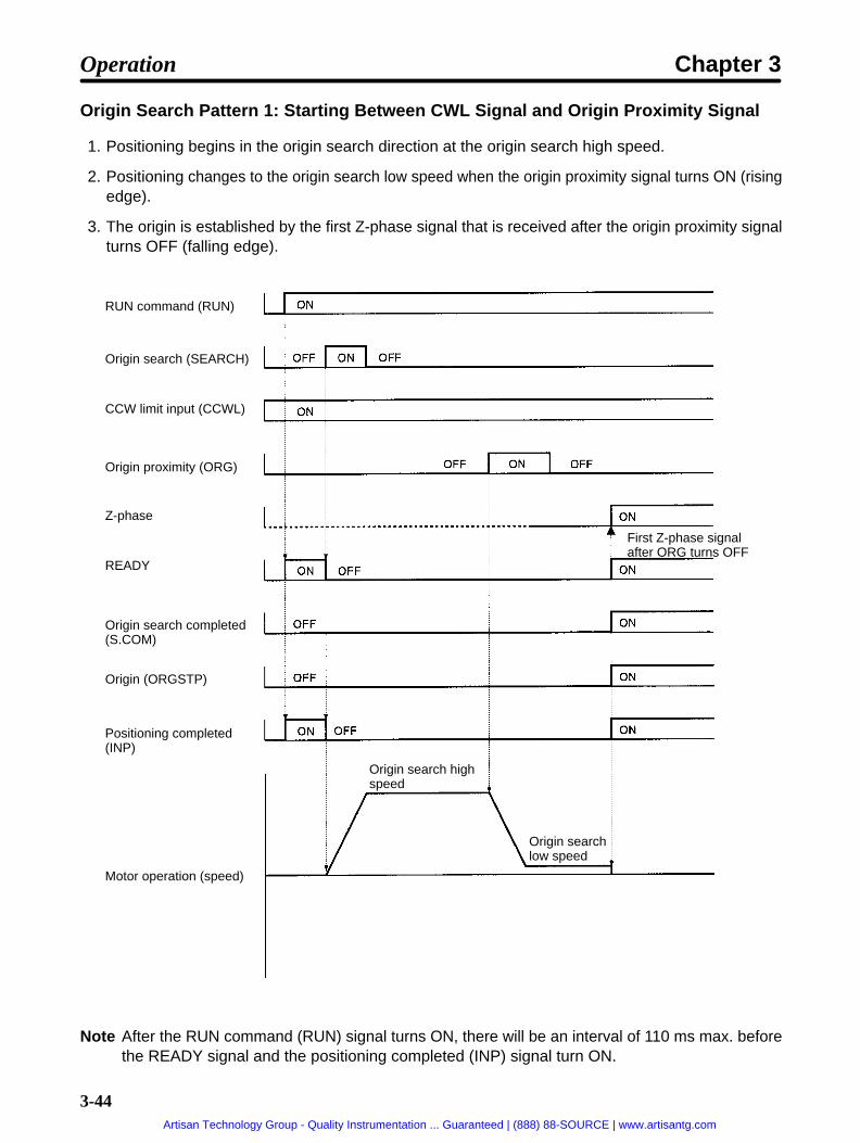
3-44
Origin Search Pattern 1: Starting Between CWL Signal and Origin Proximity Signal
1. Positioning begins in the origin search direction at the origin search high speed.
2. Positioning changes to the origin search low speed when the origin proximity signal turns ON (risingedge).
3. The origin is established by the first Z-phase signal that is received after the origin proximity signalturns OFF (falling edge).
RUN command (RUN)
Origin search (SEARCH)
CCW limit input (CCWL)
Origin proximity (ORG)
Z-phase
READY
Origin search completed(S.COM)
Origin (ORGSTP)
Positioning completed(INP)
Motor operation (speed)
First Z-phase signalafter ORG turns OFF
Origin search highspeed
Origin searchlow speed
Note After the RUN command (RUN) signal turns ON, there will be an interval of 110 ms max. beforethe READY signal and the positioning completed (INP) signal turn ON.
Operation Chapter 3
Artisan Technology Group - Quality Instrumentation ... Guaranteed | (888) 88-SOURCE | www.artisantg.com
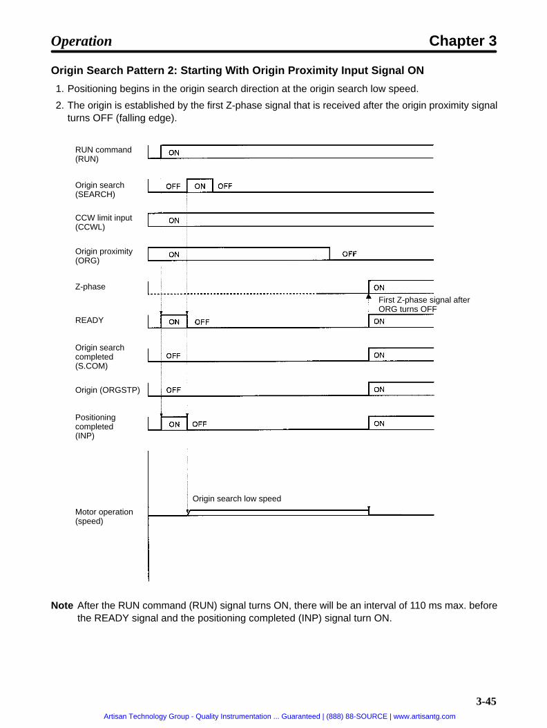
3-45
Origin Search Pattern 2: Starting With Origin Proximity Input Signal ON
1. Positioning begins in the origin search direction at the origin search low speed.
2. The origin is established by the first Z-phase signal that is received after the origin proximity signalturns OFF (falling edge).
RUN command(RUN)
Origin search(SEARCH)
CCW limit input(CCWL)
Origin proximity(ORG)
Z-phase
READY
Origin searchcompleted(S.COM)
Origin (ORGSTP)
Positioningcompleted(INP)
Motor operation(speed)
First Z-phase signal afterORG turns OFF
Origin search low speed
Note After the RUN command (RUN) signal turns ON, there will be an interval of 110 ms max. beforethe READY signal and the positioning completed (INP) signal turn ON.
Operation Chapter 3
Artisan Technology Group - Quality Instrumentation ... Guaranteed | (888) 88-SOURCE | www.artisantg.com

3-46
Origin Search Pattern 3: Starting Between Origin Proximity Signal and CCWL Signal
1. Positioning begins in the origin search direction at the origin search high speed.
2. The direction of movement is reversed when the CCWL signal turns OFF.
3. When the origin proximity signal turns from ON to OFF, the direction of movement is reversed againand the speed is changed to the origin search low speed.
4. The origin is established by the first Z-phase signal that is received after the origin proximity signalturns OFF.
RUN command(RUN)
Origin search(SEARCH)
CCW limit input(CCWL)
Origin proximity(ORG)
Z-phase
READY
Origin searchcompleted(S.COM)
Origin (ORGSTP)
Positioningcompleted(INP)
Motor operation(speed)
First Z-phase signal afterORG turns OFF
Origin search low speed
Origin searchhigh speed
Origin search high speed
Note After the RUN command (RUN) signal turns ON, there will be an interval of 110 ms max. beforethe READY signal and the positioning completed (INP) signal turn ON.
Operation Chapter 3
Artisan Technology Group - Quality Instrumentation ... Guaranteed | (888) 88-SOURCE | www.artisantg.com
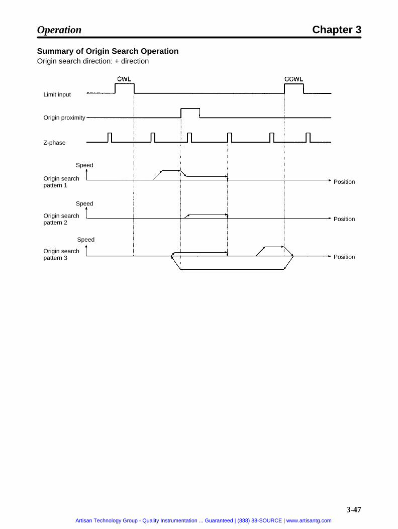
3-47
Summary of Origin Search OperationOrigin search direction: + direction
Limit input
Origin proximity
Z-phase
Origin searchpattern 1
Position
Origin searchpattern 2
Origin searchpattern 3
Speed
Speed
Speed
Position
Position
Operation Chapter 3
Artisan Technology Group - Quality Instrumentation ... Guaranteed | (888) 88-SOURCE | www.artisantg.com

3-48
Origin Search Example Program (SYSMAC C200H-HX/HG/HE)
The following ladder program example (for SYSMAC C200H-HX/HG/HE) is provided forreference
Word AllocationIn this program example, the I/O signals are allocated to the input and output words as follows:
Output Unit: Word 0Bit number Position Driver signal name
0 RUN RUN command
1 START Start
2 RESET Alarm reset
3 SEARCH Origin search
4 +JOG +JOG operation
5 –JOG –JOG operation
6 TEACH Teach
7 STOP Deceleration stop
8 P.IN0 Point selection 0 / Position 0
9 P.IN1 Point selection 1 / Position 1
10 P.IN2 Point selection 2 / Position 2
11 P.IN3 Point selection 3 / Position 3
12 P.IN4 Point selection 4 / Position 4
13 P.IN5 Point selection 5 / Position 5
14 P.IN6 Point selection 6 / Position 6
15 P.IN7 Position 7
Input Unit: Word 8Bit number Position Driver signal name
0 BO Brake output
1 READY Ready
2 S.COM Origin search completed
3 ORGSTP Origin stop
4 T.COM Teaching completed
5 RUNON Motor running
6 INP Positioning completed
7 ALM Alarm
8 P.OUT0 Point output 0 / Position selection 1
9 P.OUT1 Point output 1/ Position selection 2
10 P.OUT2 Point output 2 / Position selection 3
11 P.OUT3 Point output 3/ Position selection 4
12 P.OUT4 Point output 4/ Speed selection
13 P.OUT5 Point output 5
14 P.OUT6 Point output 6
15 (Not used.)
Operation Chapter 3
Artisan Technology Group - Quality Instrumentation ... Guaranteed | (888) 88-SOURCE | www.artisantg.com

3-49
IR AreaWord 30 in the IR area is used.
Ladder Program• For this example program it is assumed that limit input signals (CCWL and CWL) and origin proximity
signals used for origin search operations are directly input from the sensors.
• There are three types of origin search, depending on the beginning position for the search, but for thepurposes of this ladder program example they are all the same. (So there is no need to change theorigin search pattern.)
• The program uses bits in IR 30.
0000
DIFU(013) 30000
RUN switch 0807
ORIGIN SEARCH switch
0003
3000 0801
3001
3002
3001
3002
RUN command signal output
Origin search signal output
An error is output if the originsearch signal is input while theready signal is OFF.
(READY)
Origin search error
Origin search
(RUN)
Origin search error check switch
0801
0007
3300 (DECELERATION STOP switch)(STOP) (See note 2.)
3003
Note 1. A CompoBus/S-type Position Driver can also be used by changing the word allocation. Fordetails regarding word allocations, refer to the Master Unit operation manual.
Note 2. Bit allocation will be made for the deceleration stop (STOP) signal when using a CompoBus/S-type Position Driver. In this case, the deceleration stop (STOP) signal must be turned ON inthe ladder program. (If the deceleration stop signal for external control input (CN 4-4), or lad-der program input (OUT 7) is OFF, the motor will not run.)
3-7-2 Origin Teaching
Function• The origin teaching operation sets any given position as the mechanical origin.
• If the motor sensor’s Z-phase position (the origin search completion position) is not at the desiredmechanical origin after an origin search operation, it will be possible to move to any given position anduse the origin teaching operation to make that position the mechanical origin (present value 0).
Operation Chapter 3
Artisan Technology Group - Quality Instrumentation ... Guaranteed | (888) 88-SOURCE | www.artisantg.com

3-50
• The amount of movement at this time is taken by the PTP parameters (PP-06, PP-07) as the origincompensation, and in subsequent origin search operations this value is used to move to the originteaching position (the mechanical origin) to complete the origin search.
Note Origin teaching cannot be executed if the origin is not established.
PTP ParametersThe following PTP parameters are set by the origin teaching operation.
No.PP-
Name Min.unit
Settingrange
Factorysetting
Explanation
06 Origin compensation(leftmost digits)
1 pulse –9,999to9,999
0 Specifies number of motor sensor pulses formovement between origin search completionposition and mechanical origin. The value can
07 Origin compensation(rightmost digits)
0 to9,999
0
gbe obtained by origin teaching.
Operation1. Complete the origin search operation.
2. Use the JOG operation or external force (with servo OFF) to move to the mechanical origin.
3. Turn OFF the RUN command (if the JOG operation has been used).
4. Turn ON the origin search (SEARCH) command, and then turn ON the teaching (TEACH) com-mand. (When the origin teaching operation has been completed, the teaching completed signal(T.COM) turns ON.
RUN command(RUN)
Origin search(SEARCH)
READY
Origin searchcompleted(S.COM)
Origin (ORGSTP)
Positioningcompleted (INP)
Motor operation
Teaching (TEACH)
RUN signal ON when JOG operation used for movement.
Movement by JOG operationor external force
Teaching completed(T.COM)
Operation Chapter 3
Artisan Technology Group - Quality Instrumentation ... Guaranteed | (888) 88-SOURCE | www.artisantg.com

3-51
3-7-3 Teaching
Function• The teaching operation takes the motor’s present value as the position data in the specified PTP data.
• Teaching is only enabled when the control mode is set for point positioning (UP-01: 11 or 12).
• The position data that is taken by the teaching operation is all absolute-value (A) data. Also, the speeddata, acceleration/deceleration selection, and operation mode selection do not change. (Make thesettings after teaching is completed.)
• Teaching can be executed with the RUN command either ON or OFF, so it can be executed while themechanical system is being moved by either the JOG operation or external force.
Note Teaching cannot be executed if the origin is not established.
PTP ParametersThe following PTP parameters are set by the teaching operation.
No.Pd-
Name Min.unit
Settingrange
Factorysetting
Explanation
H Point No.
position data(leftmost digits)
(PP-01) (I/A)–3,999to3,999
(I) 0 Specifies point no. position data.A value between –39,999,999 and39,999,999 can be set. Leftmost digit is usedto specify “A” (absolute) or “I” (incremental)value.N t 1 t b f 01
L Point No.
position data(rightmost digits)
(PP-01) 0 to9,999
0 Note 1. represents a number from 01to 64.
Note 2. With teaching, the position data is A(absolute value)
Operation (Example: Teaching With JOG)1. Input to points 0 to 6 (P.IN0 to 6) the point numbers to be taught. (Make sure that they match the
numbers for point outputs 0 to 6 (P.OUT0 to 6).
2. Use the JOG operation (+JOG or –JOG) to rotate the motor.
3. Move to the position that is to be taught, and then turn ON the teaching (TEACH) input.
Operation Chapter 3
Artisan Technology Group - Quality Instrumentation ... Guaranteed | (888) 88-SOURCE | www.artisantg.com

3-52
4. When the teaching completed signal (T.COM) turns ON, turn OFF the teaching (TEACH) input.
RUN command (RUN)
READY
Positioning completed(INP)
Teaching (TEACH)
+JOG operation (+JOG)
Point selection(P.INP0 to 6)
Teaching completed(T.COM)
Point output(P.OUT0 to 6)
Point No. n
Point No. n
Motor operation
3-7-4 Point Positioning (UP-01: 11 or 12)
Function• Positioning is executed according to the PTP data of point numbers input to P.IN0 to P.IN6.
• Positioning is started when the start signal is turned ON while the ready signal is ON.
• The ready signal is turned OFF at the moment positioning begins and turned ON again upon comple-tion of the positioning operation.
Note With feeder control (UP-01: 12), the present value is cleared when the start signal is turned ON.
Operation
1. Input the point numbers to P.IN0 to P.IN6. (Make sure that the P.OUT0 to P.OUT6 signals match thepoint numbers input to P.IN0 to P.IN6.)
2. Make sure that the ready signal is ON. Then turn ON the start signal.
3. Positioning will begin and the ready signal will be turned OFF.
Operation Chapter 3
Artisan Technology Group - Quality Instrumentation ... Guaranteed | (888) 88-SOURCE | www.artisantg.com

3-53
4. The ready signal will be turned ON again upon completion of the positioning.
RUN command(RUN)
Start (START)
Point selection(P.IN0 to P.IN6)
READY
Positioning completion(INP)
Point output(P.OUT0 to P.OUT6)
Motor operation
Point no. m Point no. n
Point no. m Point no. n
Independentoperation mode
Automaticincrementalmode
Continuousoperationmode
Independentoperationmode
Point Positioning Program Example (C200H-HX/HG/HE)
The following point positioning ladder program example (for SYSMAC C200H-HX/HG/HE) is provided for reference
Word AllocationIn this program example, the I/O signals are allocated to the input and output words as follows:
Output Unit: Word 0Bit number Position Driver signal name
0 RUN RUN command
1 START Start
2 RESET Alarm reset
3 SEARCH Origin search
4 +JOG +JOG operation
5 –JOG –JOG operation
6 TEACH Teach
7 STOP Deceleration stop (See note 2.)
8 P.IN0 Point selection 0 / Position 0
9 P.IN1 Point selection 1 / Position 1
10 P.IN2 Point selection 2 / Position 2
Operation Chapter 3
Artisan Technology Group - Quality Instrumentation ... Guaranteed | (888) 88-SOURCE | www.artisantg.com

3-54
Bit number Position Driver signal name11 P.IN3 Point selection 3 / Position 3
12 P.IN4 Point selection 4 / Position 4
13 P.IN5 Point selection 5 / Position 5
14 P.IN6 Point selection 6 / Position 6
15 P.IN7 Position 7
Input Unit: Word 8Bit number Position Driver signal name
0 BO Brake output
1 READY Ready
2 S.COM Origin search completed
3 ORGSTP Origin stop
4 T.COM Teaching completed
5 RUNON Motor running
6 INP Positioning completed
7 ALM Alarm
8 P.OUT0 Point output 0 / Position selection 1
9 P.OUT1 Point output 1/ Position selection 2
10 P.OUT2 Point output 2 / Position selection 3
11 P.OUT3 Point output 3/ Position selection 4
12 P.OUT4 Point output 4/ Speed selection
13 P.OUT5 Point output 5
14 P.OUT6 Point output 6
15 (Not used.)
DM AreaDM No. Data contents
00 Point number
01 Input signal
02 Output signal
IR AreaWord 30 in the IR area is used.
Note 1. A CompoBus/S-type Position Driver can also be used by changing the word allocation. Fordetails regarding word allocations, refer to the Master Unit operation manual.
Note 2. Bit allocation will be made for the deceleration stop (STOP) signal when using a CompoBus/S-type Position Driver.
Note 3. Point numbers 0 to 64 (BCD) are input to P.IN0 to P.IN6 and output from P.OUT0 to P.OUT6.
Input to the Position DriverP.IN6 P.IN5 P.IN4 P.IN3 P.IN2 P.IN1 P.IN0
4 101 2 101 1 101 8 100 4 100 2 100 1 100
Output from the Position DriverP.OUT6 P.OUT5 P.OUT4 P.OUT3 P.OUT2 P.OUT1 P.OUT0
4 101 2 101 1 101 8 100 4 100 2 100 1 100
Operation Chapter 3
Artisan Technology Group - Quality Instrumentation ... Guaranteed | (888) 88-SOURCE | www.artisantg.com

3-55
Ladder Program
MOVD(083)D0000
#0210
00
0000
DIFU(013)3100
RUN switch 0807
Point No. setting switch
3101
3100
3101
3101
0801
3102
3103
3102
3103
ANDW(034)00
#7F00
D0001
ANDW(034)08
#7F00
D0002
CMP(020)D0001
D0002
3104
3103
(READY)
0801
25506(=)
3105
3104
3105
DIFU(013)3200
0001
3200
3201
3202
3203
3202
3201
3106
(Alarm output)
(READY)
(Point number check switch)
(START error check switch)
START switch
(READY)
(RUN)
Outputs point number toleftmost 8 bits of word 00.
Moves point number input(control input) to DM 0001.
Moves point number output(control output) to DM 0002.
Compares point number I/O.
Point number setting completed
START
START error
RUN command signal output
Point number setting
Point number setting check.
START signal output
An error is output if the STARTsignal is input while the readysignal is OFF.
0801
0801
0007
3300 (DECELERATION STOP switch)(STOP) (See note 3.)
3102
3104
Operation Chapter 3
Artisan Technology Group - Quality Instrumentation ... Guaranteed | (888) 88-SOURCE | www.artisantg.com

3-56
Note 1. The point number setting switch is a contact for taking the point number (DM 00) into the Posi-tion Driver.
Note 2. Turn ON the point number check switch (3106) and the START switch when “point numbersetting completed” (3105) is output.
Note 3. When using a CompoBus/S-type Position Driver, the deceleration stop (STOP) signal mustbe turned ON in the ladder program. (If the deceleration stop signal for external control input(CN 4-4), or ladder program input (OUT 7) is OFF, the motor will not run.)
3-7-5 Direct Positioning (UP-01: 13 or 14)
Function• Positioning is executed by taking in sequence the position and speed data entered for positions 0 to 7
(P.IN0 to 7), according to the timing output signals for position data selections 1 to 4 (P.OUT0 to 3) andthe speed data selection (P.OUT4).
• When the teach signal is turned ON, the Position Driver starts reading the data. Both the teachingcompleted (T.COM) and ready signals are turned ON when the Position Driver has finished readingthe data.
• Positioning is started when the start signal is turned ON while the ready signal is ON.
• The ready signal is turned OFF during positioning and turned ON again upon completion of the posi-tioning operation.
Note With feeder control (UP-01: 12), the present value is cleared when the start signal is turned ON.
Operation1. The two rightmost digits of the position data are input to P.IN0 to P.IN7.
2. The teach signal is turned ON. Position selection 1 (P.OUT0) are turned ON and OFF and the posi-tion data is taken at the falling edge.
3. Next position selection 2 (P.OUT1 is turned ON. While P.OUT1 is ON, positions 0 to 7 are taken intothe third and fourth digits.
4. The remaining position data (i.e., the rest of the digits, sign bit, and I/A bit) and speed data are takenin the same way.
5. After all the data has been taken, both the teaching completed (T.COM) and ready signals areturned ON. After it is confirmed that they have turned ON, the teach signal is turned OFF.
6. When the start signal is turned ON, positioning begins and the ready signal is turned OFF.
Operation Chapter 3
Artisan Technology Group - Quality Instrumentation ... Guaranteed | (888) 88-SOURCE | www.artisantg.com

3-57
7. The ready signal is turned ON again upon completion of the positioning operation.
RUN command(RUN)
Teaching(TEACH)
Start(START)
Position data(P.IN0 to P.IN7)
Teaching completed(T.COM)
READY(READY)
Positioning completed(INP)
Position selection 1(P.OUT0)
Position selection 2(P.OUT1)
Position selection 3(P.OUT2)
Position selection 4(P.OUT3)
Speed selection(P.OUT4)
Motor operation
Selection signal output timecan be set in PP-26.
Operation Chapter 3
Artisan Technology Group - Quality Instrumentation ... Guaranteed | (888) 88-SOURCE | www.artisantg.com

3-58
Direct Positioning Program Example (C200H-HX/HG/HE)
The following direct positioning ladder program example (for SYSMAC C200H-HX/HG/HE) is provided for reference.
Word AllocationIn this program example, the I/O signals are allocated to the input and output words as follows:
Output Unit: Word 0Bit number Position Driver signal name
0 RUN RUN command
1 START Start
2 RESET Alarm reset
3 SEARCH Origin search
4 +JOG +JOG operation
5 –JOG –JOG operation
6 TEACH Teach
7 STOP Deceleration stop (See note 2.)
8 P.IN0 Point selection 0 / Position 0
9 P.IN1 Point selection 1 / Position 1
10 P.IN2 Point selection 2 / Position 2
11 P.IN3 Point selection 3 / Position 3
12 P.IN4 Point selection 4 / Position 4
13 P.IN5 Point selection 5 / Position 5
14 P.IN6 Point selection 6 / Position 6
15 P.IN7 Position 7
Input Unit: Word 8Bit number Position Driver signal name
0 BO Brake output
1 READY Ready
2 S.COM Origin search completed
3 ORGSTP Origin stop
4 T.COM Teaching completed
5 RUNON Motor running
6 INP Positioning completed
7 ALM Alarm
8 P.OUT0 Point output 0 / Position selection 1
9 P.OUT1 Point output 1/ Position selection 2
10 P.OUT2 Point output 2 / Position selection 3
11 P.OUT3 Point output 3/ Position selection 4
12 P.OUT4 Point output 4/ Speed selection
13 P.OUT5 Point output 5
14 P.OUT6 Point output 6
15 (Not used.)
Operation Chapter 3
Artisan Technology Group - Quality Instrumentation ... Guaranteed | (888) 88-SOURCE | www.artisantg.com

3-59
DM AreaDM number Data contents
01 Input signal
02 Output signal
10 Positioning data (rightmost digits)
11 Positioning data (leftmost digits)
12 Speed data
20 Indirect table for positioning data
21 Digit transfer control data table
IR AreaWord 30 in the IR area is used.
Note 1. A CompoBus/S-type Position Driver can also be used by changing the word allocation. Fordetails regarding word allocations, refer to the Master Unit operation manual.
Note 2. Bit allocation will be made for the deceleration stop (STOP) signal when using a CompoBus/S-type Position Driver.
Note 3. Input position data (BCD) and speed data (BCD) into P.IN 0 to 7 with P.OUT0 to 4.
P.IN7 P.IN6 P.IN5 P.IN4 P.IN3 P.IN2 P.IN1 P.IN0
8 10n+1 4 10n+1 2 10n+1 1 10n+1 8 10n 4 10n 2 10nn 1 10n
Position data: P.OUT0 ON; n=0, P.OUT1 ON; n=2, P.OUT2 ON; n=4, P.OUT3 ON; n=6P.IN6; ±data 0: +, 1: – P.IN7; INC/ABS data 0: INC, 1: ABS
Speed data: P.OUT4 ON; n=0
Operation Chapter 3
Artisan Technology Group - Quality Instrumentation ... Guaranteed | (888) 88-SOURCE | www.artisantg.com

3-60
Ladder Program
MOV(021)#0010
D0020
0000
DIFU(013)3100
RUN switch 0807
Data input switch
3101
3100
3101
0006
3101
0006
MOV(021)#0010
D0020
0808(P.OUT0)0808(P.OUT0)
MOV(021)#0210
D0021
MOV(021)#0212
D0021
MOV(021)#0011
D0020
0810(P.OUT2)
MOV(021)#0210
D0021
MOV(021)#0011
D0020
0811(P.OUT3)
MOV(021)#0212
D0021
MOV(021)#0012
D0020
0812(P.OUT4)
MOV(021)#0210
D0021
0809(P.OUT1)
0801
(Alarm output)
(READY)
(RUN)
(TEACH)
RUN command signal output
Transfer information for right-most digits of position data
Transfer information for left-most digits of position data
Transfer information forspeed data
3102
0007
3300 (DECELERATION STOP switch)(STOP) (See note 3.)
Operation Chapter 3
Artisan Technology Group - Quality Instrumentation ... Guaranteed | (888) 88-SOURCE | www.artisantg.com

3-61
DIFU(013)3102
ANDW(034)00
#00FF
D0001
MOVD(083)*D0020
D0021
D0002
ANDW(034)D0002
#FF00
D0002
ORW(035)D0001
D0002
00
0811
08043101
3105
3102
3105
0810
DIFU(013)3200
START switch
0001
3201
3202
3201
3202
0801
3200 0801
0808
0809
Positioning data settings
Releases controlinputs to DM 01.
Transfers positioningdata in 8-bit units tothe leftmost 8 bits ofDM 02.
Clears rightmost8 bits of DM 02.
Adds released controlinputs and positioningdata and outputs result toword 00.
(Teaching completed)
(Position data intake check switch)Position data intake completed
(READY)
(START error check switch)
START error
START
START signal output
An error is output if theSTART signal is inputwhile the ready signal isOFF.
0812
3106
3203
Note 1. The data input switch is a contact for taking the set position data into the Position Driver.
Note 2. Turn ON the position data intake switch (3106) and the START switch when “position dataintake completed” (3105) is output.
Note 3. When using a CompoBus/S-type Position Driver, the deceleration stop (STOP) signal mustbe turned ON in the ladder program. (If the deceleration stop signal for external control input(CN 4-4), or ladder program input (OUT 7) is OFF, the motor will not run.)
Operation Chapter 3
Artisan Technology Group - Quality Instrumentation ... Guaranteed | (888) 88-SOURCE | www.artisantg.com

3-62
3-8 Trial Operation
After the wiring is complete and the parameter settings have been made, conduct a trialoperation. First, in system check mode, check the motor’s rotation direction without con-necting a load (i.e., without connecting the mechanical system), and check to be surethat the I/O signals are correctly wired. Then, connect the mechanical system, auto-tunethe system, and confirm that the correct operation pattern is performed. If an erroroccurs during trial operation, refer to Chapter 4 Application and apply the appropriatemeasures.
3-8-1 Trial Operation Procedure
Preparations
Turning OFF the Power SupplyThe power supply must be turned OFF and back ON in order for some of the parameter settings to gointo effect, so always turn OFF the power supply before starting.
Leaving the Motor With No Load ConnectedDo not connect a load to the motor shaft during trial operation in case the motor runs out of control.
Preparing to Stop the MotorMake sure that the power switch can be turned OFF or the RUN command can be used to stop the motorimmediately in case of trouble.
Actual Trial Operation(1) Powering Up
• With the RUN command OFF, apply an AC voltage.• After internal initialization, the mode will be the Monitor Mode.
r 0Monitor display example:
• Set the speed loop proportional gain (AJ2.) to approximately 1.0. (Match the gain with no load.)
1. Confirm the initial display (Monitor Mode) shown above.
2. Press the Mode Key twice to enter the Adjustment Parameters Edit Mode.
3. Press the Increment Key to display the contents of AJ2. (speed loop proportional gain).
4. Press the Shift Key and Data Key to enable the data to be changed. (The digit that can be changedwill flash.)
5. Press the Shift Key, Increment Key, or Decrement Key as required to change the setting to 1.0.
6. Press the Data Key to end the data change operation.
Operation Chapter 3
Artisan Technology Group - Quality Instrumentation ... Guaranteed | (888) 88-SOURCE | www.artisantg.com

3-63
Note 1. The factory setting for the speed loop proportional gain (AJ2.) is 1.0 (multiple).
Note 2. In the Adjustment Parameters Edit Mode, the set value is re-written at the point where thenumber is changed by pressing the Increment Key and Decrement Key.
(2) Testing the Motor (Refer to 3-8-2 System Check Mode.)
• Execute the motor test operation in System Check Mode and perform the following checks.
Is the motor’s rotation direction correct?
Are there any abnormal sounds or vibration?
Is anything abnormal occurring?(3) Checking the I/O Signal Wiring
• Execute the output signal test in System Check Mode and perform the following check. (Refer to 3-8-2System Check Mode.)
Are signals from the Position Driver being correctly read by the host controller?
• Check the following item with the Check Mode’s I/O signal display. (Refer to 4-2 Check Mode.)
Are signals and limit inputs from the host controller, origin proximity signals, deceleration stop inputsignals, and so on, being correctly read by the Position Driver?
(4) Auto-tuning With a Load Connected (Refer to 3-9 Making Adjustments.)
• Connect the motor shaft to the load (mechanical system) securely, being sure to tighten screws so thatthey will not become loose.
• Execute auto-tuning in System Check Mode.(5) Turning ON the RUN Command Input
• Turn ON the run command input.• Check to be sure that the motor goes into servo-lock status.
(6) Operating at Low Speed• Operate the motor at low speed.
The meaning of “low speed” can vary with the mechanical system. Here, “low speed” means approxi-mately 10% to 20% of the actual operating speed.
• Check the following items.Is the emergency stop operating correctly?Are the limit switches operating correctly?Is the operating direction of the machinery correct?Are the operating sequences correct?Are there any abnormal sounds or vibration?Is anything abnormal occurring?
(7) Operating Under Normal Load Conditions• Operate the motor in a regular pattern and check the following items.
Is the speed correct? (Use the Monitor Mode’s motor speed display and the mechanical speeddisplay.)Is the load torque roughly equivalent to the measured value? (Use the Monitor Mode’s motor cur-rent display and the effective load factor display.)Are the positioning points correct?When an operation is repeated, is there any discrepancy in positioning?Are there any abnormal sounds or vibration?Is either the motor or the Driver abnormally overheating?Is anything abnormal occurring?
Operation Chapter 3
Artisan Technology Group - Quality Instrumentation ... Guaranteed | (888) 88-SOURCE | www.artisantg.com

3-64
(8) Readjusting the Gain
• If the gain could not be adjusted completely using auto-tuning, perform the procedure in 3-9 MakingAdjustments to adjust the gain manually.
3-8-2 System Check ModeThe System Check Mode is used to conduct the motor test, output signal test, and auto-tuning. To enterthis mode, use the following procedure:
1. Press the Mode Key to go into the Monitor Mode.
2. Hold down the Increment Key, Decrement Key, and Data Key simultaneously for at least fiveseconds to go into the System Check Mode.
To exit the System Check Mode, double-click the Mode Key.
Note The motor test operation is a function for operating the motor with only the Position Driver and themotor. The limit inputs and deceleration stop input are disabled, so before conducting this testcheck to make sure that there will be no adverse effect on the equipment.
Entering the System Check ModeThe System Check Mode can be entered from the Monitor Mode.
Monitor Mode
Hold down the Incre-ment Key, DecrementKey, and Data Keysimultaneously for atleast five seconds.
Double-click the Mode Key.
System Check Mode
Motor test
Output signal test
Auto-tuning
AdS display
Functions in System Check Mode
Motor Test Operation• With the motor test operation, the motor is operated in forward and reverse by means of key opera-
tions with just the motor and Position Driver connected. (Connection to a host controller is notrequired.)
• The motor speed can be set by UP-29 (motor test r/min). The factory setting is 50 r/min.
Output Signal Test• With the output signal test, Position Driver output signals are turned ON and OFF.
• This test is used to check the connections with the host controller.
Operation Chapter 3
Artisan Technology Group - Quality Instrumentation ... Guaranteed | (888) 88-SOURCE | www.artisantg.com

3-65
Auto-tuning• With auto-tuning, the size and characteristics of the load (the mechanical system) can be checked,
and the gain can be automatically adjusted and set accordingly.
• There are three kinds of gain to be set: position loop gain (AJ.4), speed loop proportional gain (AJ.2),and speed loop integral gain (AJ.3).
• There are three parameters for auto-tuning: reciprocating rotation range (Auto1), target response fre-quency (Auto2), and maximum rotation speed (Auto3).
Note For details regarding auto-tuning, refer to 3-9 Making Adjustments.
AdS DisplayThis is a parameter for manufacturer adjustments. Do not change the setting.
Motor Test Operation ProcedureDisplay example Key operation
Press the Mode Key to enter Monitor Mode.
Hold down the Increment Key, Decrement Key, and Data Key simultaneously for atleast five seconds to enter System Check Mode.
Press the Data Key to go to servo-ON status.
Press the Increment Key to test forward operation. (The motor should rotate in theforward direction while the Increment Key is being held down.)
Press the Decrement Key to test reverse operation. (The motor should rotate inthe reverse direction while the Decrement Key is being held down.)
Press the Data Key to go to servo-OFF status.
Double-click the Mode Key to return to Monitor Mode.
User Parameter SettingsThe motor speed can be set by UP-29 (motor test r/min).
No.UP-
Name Min.unit
Settingrange
Factorysetting
Explanation
29 Motor test r/min 1 r/min 1 to8,000
50 Specifies the motor speed during the motortest operation.
Note Be sure to set this parameter to no more than the motor’s rated speed.
Operation Chapter 3
Artisan Technology Group - Quality Instrumentation ... Guaranteed | (888) 88-SOURCE | www.artisantg.com

3-66
Output Signal Test Operating ProcedureDisplay example Key operation
Press the Mode Key to enter Monitor Mode.
Hold down the Increment Key, Decrement Key, and Data Key simultaneously for atleast five seconds to enter System Check Mode.
Press the Shift Key to bring up the output signal test display.
Press the Data Key and Shift Key to enable the output signal test. (The outputsignals will all be turned OFF.)
Use the Increment Key and the Decrement Key to select the signal. In thisexample the origin signal (ORGSTP) is selected.
Press the Data Key to turn ON the output signal. (“1” indicates “ON.”)
Press the Data Key again to turn OFF the output signal. (“1” indicates “OFF.”)
Press the Mode Key to return to the output signal test display.
Double-click the Mode Key to return to Monitor Mode.
Output Signal Numbers, Symbols, and NamesNumber Symbol Name
S00 READY READY
S01 S.COM Origin search completed
S02 ORGSTP Origin stop
S03 T.COM Teaching completed
S04 RUNON Motor running
S05 INP Positioning completed
S06 ALM Alarm
S07 P.OUT0 Point output 0 / Position selection 1
S08 P.OUT1 Point output 1 / Position selection 2
S09 P.OUT2 Point output 2 / Position selection 3
S10 P.OUT3 Point output 3 / Position selection 4
S11 P.OUT4 Point output 4 / Speed selection
S12 P.OUT5 Point output 5
S13 P.OUT6 Point output 6
S14 BO Brake output
Operation Chapter 3
Artisan Technology Group - Quality Instrumentation ... Guaranteed | (888) 88-SOURCE | www.artisantg.com

3-67
3-9 Making Adjustments
3-9-1 Auto-tuning
Auto-tuning is a function for automatically operating the motor to adjust the position loopgain, speed loop proportional gain, and speed loop integral gain.If adjustments cannot be made by auto-tuning, refer to 3-9-2 Manually Adjusting Gain.When using auto-tuning, the limit inputs and deceleration stop input must be connected.
Basic Auto-tuning Procedure• To go into auto-tuning, first enter the System Check Mode from the Monitor Mode, and then press the
Shift Key to bring up the auto-tuning display.
• After setting the auto-tuning parameters, press the Data Key and Increment Key simultaneously tobegin the auto-tuning operation.
• When the auto-tuning operation has been completed, double-click the Mode Key to return to the Moni-tor Mode.
Monitor Mode
Hold down the Incre-ment Key, DecrementKey, and Data Keysimultaneously for atleast five seconds.
Double-click the Mode Key.
System Check Mode
Motor test
Output signal test
Auto-tuning display
Auto-tuning
Executes auto-tuning operation.
Auto-tuning in progress.(Display flashes and motor operates.)
Auto-tuning completed.
Auto-tuning Parameter SettingsDisplay Name Min.
unitSettingrange
Factorysetting
Explanation
Auto 1 Reciprocatingrotation width
1 rev. 1 to300
1 Specifies the amount to move to one sidein reciprocating operation duringauto-tuning execution.
Auto 2 Destination cutofffrequency
1 Hz 1 to100
40 Specifies the position loopresponsiveness. (Normally set from 20 Hzto 80 Hz.)
Auto 3 Maximum rotationspeed
1 r/min 1 to4,000
1,000 Specifies the maximum motor speedduring auto-tuning execution.
Operation Chapter 3
Artisan Technology Group - Quality Instrumentation ... Guaranteed | (888) 88-SOURCE | www.artisantg.com
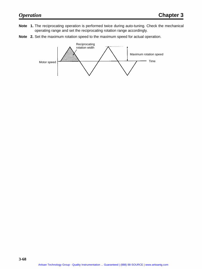
3-68
Note 1. The reciprocating operation is performed twice during auto-tuning. Check the mechanicaloperating range and set the reciprocating rotation range accordingly.
Note 2. Set the maximum rotation speed to the maximum speed for actual operation.
Motor speed
Reciprocatingrotation width
Maximum rotation speed
Time
Operation Chapter 3
Artisan Technology Group - Quality Instrumentation ... Guaranteed | (888) 88-SOURCE | www.artisantg.com

3-69
Operating Procedure Example
In this auto-tuning example, it is assumed that the reciprocating rotation range is set to 5 (revolutions),the target response frequency is set to 50 (Hz), and the maximum rotation speed is set to 2,000 (r/min).
Display example Key operation
Press the Mode Key to enter Monitor Mode.
Hold down the Increment Key, Decrement Key, and Data Key simultaneously for atleast five seconds to enter System Check Mode.
Press the Shift Key twice to bring up the auto-tuning display (reciprocating rotationrange).
Press the Increment Key to display the reciprocating rotation range data.
Press the Data Key and Shift Key to enable the data to be changed. (The digit thatcan be changed will flash.)
Use the Increment Key, the Decrement Key, and the Shift Key to change thesetting to “5.”
Press the Data Key to save the new setting.
Press the Increment Key to bring up the target response frequency display.
Press the Increment Key to display the target response frequency data.
Press the Data Key and Shift Key to enable the data to be changed. (The digit thatcan be changed will flash.)
Use the Increment Key, the Decrement Key, and the Shift Key to change thesetting to “50.”
Press the Data Key to save the new setting.
Press the Increment Key to bring up the maximum rotation speed display.
Press the Increment Key to display the maximum rotation speed data.
Press the Data Key and Shift Key to enable the data to be changed. (The digit thatcan be changed will flash.)
Use the Increment Key, the Decrement Key, and the Shift Key to change thesetting to “2000.”
Press the Data Key to save the new setting.
Press the Increment Key to bring up the auto-tuning display (reciprocating rotationrange).
Press the Data Key and the Increment Key to execute auto-tuning. (The displaywill flash while the motor is operating.)
When the display stops flashing it indicates that the auto-tuning operation iscompleted.
Double-click the Mode Key to return to Monitor Mode.
Operation Chapter 3
Artisan Technology Group - Quality Instrumentation ... Guaranteed | (888) 88-SOURCE | www.artisantg.com

3-70
Notes on Auto-tuning Settings• The reciprocating operation is performed twice during auto-tuning, so pay careful attention to the
mechanical operating range.
• The amount of movement to one side in reciprocating operation during auto-tuning is the value set inthe “Auto1” auto-tuning parameter (reciprocating operation width).
• The motor speed during auto-tuning is the value set in the “Auto3” auto-tuning parameter (maximumrotation speed).
• When auto-tuning is completed, the adjustment parameter settings for position loop gain (AJ4.),speed loop proportional gain (AJ2.), and speed loop integral gain (AJ3.) will be changed automatically.(They will not be changed until the operation has been completed.)
• If the response is not sufficient for the gain after the auto-tuning adjustments, then refer to 3-9-2 Manu-ally Adjusting Gain and adjust the gain manually.
Operation Chapter 3
Artisan Technology Group - Quality Instrumentation ... Guaranteed | (888) 88-SOURCE | www.artisantg.com

3-71
3-9-2 Manually Adjusting Gain
Gain Adjustment FlowchartPerform auto-tuning to match the rigid-ity of the mechanical system.
The motor hunts when servo-locked.(Accompanied by a hunting noise.)
Raise the Destination cutoff frequencyto the value just before hunting occursand perform auto-tuning.
Increase AJ2. (speed loop propor-tional gain) to a value where huntingdoesn’t occur in servo-lock.
Decrease AJ3. (speed loop integralgain) to a value where hunting doesn’toccur in servo-lock.
Does hunting (vibration) occurwhen the motor is operated?
Run the motor and monitor its opera-tion.
Increase AJ4. (position loop gain) untilovershooting does not occur.
Decrease the target response fre-quency so hunting doesn’t occur andperform auto-tuning.
Decrease AJ2. (speed loop proportionalgain).
Increase AJ3. (speed loop integralgain).
Decrease AJ9. (current reference filter).
End adjustment.
End adjustment.Do characteristics such as positioningtime meet system specifications?
YES
NO
YES
YES
NO
NO
When vibration can’t be eliminated despiteseveral adjustments or positioning is too slow:
WARNINGDo not make extreme adjustment or settingchanges as they cause unstable operation andmay result in injury.Perform gain adjustment by changing the valuein small increments, while checking that the mo-tor is operating normally.
!
Operation Chapter 3
Artisan Technology Group - Quality Instrumentation ... Guaranteed | (888) 88-SOURCE | www.artisantg.com

3-72
3-9-3 Adjustment Parameter DetailsPRM No. Parameter name Setting range Unit Factory setting
AJ2. Speed loop proportionalgain
0.0 to 100.0 Multiple 1.0
• This parameter adjusts the speed loop response.
• As the gain is increased, the servo rigidity is strengthened. The greater the inertia rate, the higher thisis set. If the gain is set too high, oscillation will occur.
• Adjustment can be performed more quickly by first setting the load inertia ratio.
Response When Speed Loop Proportional Gain is Adjusted
Motor speed
When speed loop proportional gain is high.(Oscillates when gain is too high.)
When speed loop proportionalgain is low.
Time
PRM No. Parameter name Setting range Unit Factory setting
AJ3. Speed loop integral gain 0.1 to 20.0 Multiple 1.0
• This parameter sets the speed loop integral gain.
• As the gain is decreased, the responsiveness is lowered and the resistance to external force is weak-ened. If the gain is set too high, oscillation will occur.
Operation Chapter 3
Artisan Technology Group - Quality Instrumentation ... Guaranteed | (888) 88-SOURCE | www.artisantg.com

3-73
Response When Speed Loop Integral Gain is Adjusted
Motor speed
Time
When speed loop integral gain is high
When speed loop integral gain is low
PRM No. Parameter name Setting range Unit Factory setting
AJ4. Position loop gain 1 to 200 rad/s 30
• Adjust the position loop response to match the mechanical rigidity.
• The servo system’s responsiveness is determined by the position loop gain. When the position loopgain is high, the servo system’s responsiveness will be high and positioning can be executed quickly.In order to increase the position loop gain, it is necessary to raise the mechanical rigidity and increasethe characteristic frequency. For normal construction machinery, set the gain to 50 to 70 (rad/s); forgeneral purpose machinery and assembly machinery, 30 to 50 (rad/s); for industrial robots, 10 to 30(rad/s).
• If the system has low mechanical rigidity or low characteristic frequency, increasing the position loopgain will cause mechanical resonance and will generate an overload alarm.
• If the position loop gain is low, the positioning time can be shortened by using feed forward.
Response When Position Loop Gain is Adjusted
When position loop gain is high
When position loop gain is low
Motor speed
Time
Operation Chapter 3
Artisan Technology Group - Quality Instrumentation ... Guaranteed | (888) 88-SOURCE | www.artisantg.com

3-74
PRM No. Parameter name Setting range Unit Factory setting
AJ7. Interrupt gain suppression 0 to 10,000 --- 0
• If any value other than “0” is set for this parameter, the speed loop integral gain will be disabled whenstopped, and the speed loop proportional gain will be suppressed.
• As the set value is increased, the amount of suppression is increased and the speed loop proportiongain is lowered.
• Adjust this parameter if the motor makes abnormal noises when stopping.
PRM No. Parameter name Setting range Unit Factory setting
AJ8. Feed-forward gain 0.0 to 2.0 Multiple 0.0
• This parameter is effective when the position loop gain is low (25 rad/s). It is not effective when theposition loop gain is high.
• Feed forward adds to the speed loop directly without going through the error counter, so responsive-ness is increased without the error counter’s integral term being entered (when the load system oper-ates without reference delays).
• Before the feed-forward gain can be adjusted, the position loop must be fully adjusted and the speedloop must be operating with stability. Check to make sure that these conditions are met before attempt-ing to adjust the feed-forward gain.
• When the feed-forward amount is set too high, the speed reference becomes like a sawtooth waveand the motor makes abnormal noises. Raise the value gradually, beginning with 0.0 (multiple).
• Make the adjustment so that the positioning completion output does not repeatedly turn ON and OFF,and so that there is no speed overshooting.
PRM No. Parameter name Setting range Unit Factory setting
AJ9. Current reference filter 400 to 20,000 rad/s 6,000
• This parameter specifies the current reference cut-off frequency.
• Gradually lower this value if vibration occurs due to a mechanical resonance frequency.
Position datacreation area
Feed forward gain
Deviationcounter
Encoder/resolver
Positionloop
Speed loop Current loop
Motor
Speed detection
Operation Chapter 3
Artisan Technology Group - Quality Instrumentation ... Guaranteed | (888) 88-SOURCE | www.artisantg.com

3-75
3-10 Regenerative Energy Absorption
Regenerative energy produced at times such as Servomotor deceleration is absorbedby the Position Driver’s internal capacitors, thereby preventing an increase in DC volt-age. If the regenerative energy from the Servomotor becomes too large, however, anovervoltage error will occur. In such cases, it is necessary to connect a RegenerationResistor to increase the regeneration processing capacity.
3-10-1 Calculating Regenerative EnergyRegenerative energy is produced when the direction of Servomotor rotation or output torque isreversed. The methods for calculating regenerative energy for the horizontal and vertical axes areexplained below.
Horizontal Axis
Motor operation
Motor outputtorque
Note In the output torque graph, acceleration in the positive direction is shown as positive, and accel-eration in the negative direction is shown as negative.The regenerative energy for each section can be found by means of the following formulas:
Eg1 = 1/2 N1 TD1 t1 1.027 × 10⁻² [J]Eg2 = 1/2 N2 TD2 t2 1.027 × 10⁻² [J]
N1, N2: Rotation speed at beginning of deceleration [r/min]TD1, TD2: Deceleration torque [kgf cm]t1, t2: Deceleration time [s]
Note There is some loss due to winding resistance, so the actual regenerative energy will be approxi-mately 90% of the figure derived by the formula.
Operation Chapter 3
Artisan Technology Group - Quality Instrumentation ... Guaranteed | (888) 88-SOURCE | www.artisantg.com

3-76
The maximum regenerative energy (Eg) occurring in any operational section can be found by means ofthe following formula:
[Unit: J]Eg is the larger of Eg1 and Eg2.
The average regenerative power per cycle of operation can be found by means of the following formula:
[Unit: W]Pr = (Eg1 + Eg2)/T [W]T: Operation cycle [s]
The maximum regenerative energy (Eg) and the average regenerative power (Pr) must not exceed theregeneration absorption capacity of the Driver. If the regeneration absorption capacity is insufficient,connect a Regeneration Resistor.
Vertical Axis
Motor operation
Falling
Rising
Motor outputtorque
Note In the output torque graph, acceleration in the positive direction (rising) is shown as positive, andacceleration in the negative direction (falling) is shown as negative.The regenerative energy for each section can be found by means of the following formulas:
Eg1 = 1/2 N1 TD1 t1 1.027 × 10⁻² [J]Eg2 = N2 TL2 t2 1.027 × 10⁻² [J]Eg3 = 1/2 N2 TD2 t3 1.027 × 10⁻² [J]
N1, N2: Rotation speed at beginning of deceleration [r/min]TD1, TD2: Deceleration torque [kgf cm]TL2: Torque when falling [kgf cm]t1, t3: Deceleration time [s]t2: Travel time equivalent to torque when falling [s]
Note There is some loss due to winding resistance, so the actual regenerative energy will be approxi-mately 90% of the figure derived by the formula.
Operation Chapter 3
Artisan Technology Group - Quality Instrumentation ... Guaranteed | (888) 88-SOURCE | www.artisantg.com

3-77
The maximum regenerative energy (Eg) occurring in any operational section can be found by means ofthe following formula:
[Unit: J]Eg is the largest of Eg1, Eg2, Eg3.
The average regenerative power per cycle of operation can be found by means of the following formula:
[Unit: W]Pr = (Eg1+ Eg2+ Eg3)/T [W]T: Operation cycle [s]
The maximum regenerative energy (Eg) and the average regenerative power (Pr) must not exceed theregeneration absorption capacity of the Driver. If the regeneration absorption capacity is insufficient,connect a Regeneration Resistor.
3-10-2 Position Driver Absorbable Regenerative EnergyThe Position Driver absorbs regenerative energy by means of an internal capacitor. If there is moreregenerative energy than can be absorbed by the capacitor, an overvoltage error will be generated andoperation cannot continue. The amounts of regenerative energy that can be absorbed by the variousPosition Drivers alone are shown in the tables below. If regenerative energy exceeding these values isproduced, take the following measures.
• Connect a Regeneration Resistor.
• Lower the operating rotation speed. (The regenerative energy is proportional to the square of therotation speed.)
• Lengthen the deceleration time. (Reduce the amount of regenerative energy per unit time.)
200-VAC Input TypeModel Regeneration processing capacity
Average regenerative power (W) Regenerative energy (J)FND-X06H- 13 17
FND-X12H- 24 17
FND-X25H- 37 22
FND-X50H- 160 38
Note The input voltage is the value at 200 VAC. As the input voltage is increased, the amount of regen-erative energy that can be absorbed is decreased.
100-VAC Input TypeModel Regeneration processing capacity
Average regenerative power (W) Regenerative energy (J)FND-X06L- 13 17
FND-X12L- 17 17
Note The input voltage is the value at 100 VAC. As the input voltage is increased, the amount of regen-erative energy that can be absorbed is decreased.
Operation Chapter 3
Artisan Technology Group - Quality Instrumentation ... Guaranteed | (888) 88-SOURCE | www.artisantg.com

!
!
3-78
3-10-3 Regenerative Energy Absorption by RegenerationResistor
If the Position Driver alone cannot absorb the regenerative energy, connect a Regeneration Resistor.The Regeneration Resistor connects between the P and J terminals at the Position Driver’s terminalblock.
Caution Be careful when connecting the Regeneration Resistor. If done incorrectly it willdamage the Position Driver.
Caution The Regeneration Resistor heats up to 120°C, so be careful not to place it nearequipment or wiring that may be affected by heat. Also be sure to install a radiationshield that satisfies the heat radiation conditions.
Selecting a Regeneration Resistor
Types of Regeneration ResistorsType Model Resistance Nominal
capacityRegenerationabsorption at
120C
Heat radiationconditions
A R88A-RR20030 30Ω 200 W 100 W t3 × 350(aluminum)
B R88A-RR40030 30Ω 400 W 200 W t3 × 350(aluminum)
Regeneration Resistor CombinationsRegeneration absorption capacity
100 W 200 W 400 W 800 WCombinationmethod
A BA
AA
A B
BB
B
Note Select a combination with a capacity greater than the average regenerative power (Pr).
Dimensions (Unit: mm)
Model L1 L2 W HR88A-RR20030 215 200 50 25
R88A-RR40030 265 250 60 30
Operation Chapter 3
Artisan Technology Group - Quality Instrumentation ... Guaranteed | (888) 88-SOURCE | www.artisantg.com

3-79
Wiring the Regeneration ResistorAs shown in the following diagram, connect the Regeneration Resistor between the P and J terminals atthe Position Driver’s terminal block.
Position Driver terminal block
RegenerationResistor
2.0 mm2
Note With the FND-X50H-, connect a Regeneration Resistor between P and JP1. In this case,remove the short bar between JP1 and JP2.
Operation Chapter 3
Artisan Technology Group - Quality Instrumentation ... Guaranteed | (888) 88-SOURCE | www.artisantg.com

Chapter 4
Application
4-1 Monitor Mode
4-2 Check Mode
4-3 Monitor Output
4-4 Protection and Diagnosis
4-5 Troubleshooting
4-6 Periodic Maintenance
4
Artisan Technology Group - Quality Instrumentation ... Guaranteed | (888) 88-SOURCE | www.artisantg.com
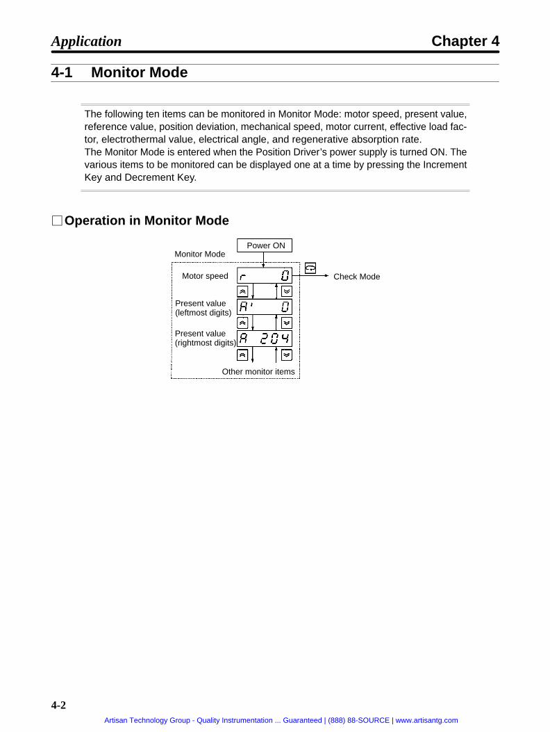
4-2
4-1 Monitor Mode
The following ten items can be monitored in Monitor Mode: motor speed, present value,reference value, position deviation, mechanical speed, motor current, effective load fac-tor, electrothermal value, electrical angle, and regenerative absorption rate.The Monitor Mode is entered when the Position Driver’s power supply is turned ON. Thevarious items to be monitored can be displayed one at a time by pressing the IncrementKey and Decrement Key.
Operation in Monitor Mode
Monitor Mode
Motor speed
Present value(leftmost digits)
Present value(rightmost digits)
Check Mode
Other monitor items
Power ON
Application Chapter 4
Artisan Technology Group - Quality Instrumentation ... Guaranteed | (888) 88-SOURCE | www.artisantg.com

4-3
Monitor DetailsDisplay Monitored item Unit Explanationr Motor speed r/min Displays the actual rotation speed of the motor
shaft.A’ Present value
(leftmost digits)Mechanical axismovement
Calculates and displays the present value of themechanical axis based on feedback from the
A Present value(rightmost digits)
movement mechanical axis based on feedback from themotor sensor.
C’ Reference value(leftmost digits)
Mechanical axismovement
Displays the mechanical axis positionreferenced by the Position Driver.
C Reference value(rightmost digits)
movement referenced by the Position Driver.
E’ Position deviation(leftmost digits)
Pulse Displays the deviation of the present value fromthe reference value with encoder/resolver
E Position deviation(rightmost digits)
the reference value with encoder/resolverresolution.
P’ (Not used.) --- ---
P (Not used.)F’ Mechanical speed
(leftmost digits)Mechanical axismovement per second
Calculates and displays the movement speed ofthe mechanical axis based on feedback from
F Mechanical speed(rightmost digits)
movement er second the mechanical axis based on feedback fromthe motor sensor.
cF (Not used.) --- ---
cc (Not used.) --- ---
L Motor current A0–P Displays the output current to the motor.
bL Effective load factor % Displays the effective load factor with respect tothe motor’s rated current value.
Effective load factor = (output current effectivevalue) / (motor’s rated current)
Effective values are calculated at the timeinterval set for HP-33 (load factor timeconstant).
oL Electrothermal value % Calculates the motor’s heat generation from theoutput current and displays it as a percentageof the heat generation in rated operation. (Whenthe power is turned ON, 90 [%] is displayed.) Ifthis value exceeds 110 [%], an A.L17 (motoroverload) alarm will be detected.
d Electrical angle deg Displays the motor’s electrical angle (0.0 to360.0).
rL Regenerativeabsorption rate
% When a Regeneration Resistor is connected,this monitor item displays the regenerativeabsorption current as a percentage of themotor’s rated current.
Note In the motor speed, present value, position deviation, mechanical speed, and motor current moni-toring displays, the respective display will flash if the value is negative. (The numeric portion willnot flash.)
Application Chapter 4
Artisan Technology Group - Quality Instrumentation ... Guaranteed | (888) 88-SOURCE | www.artisantg.com

4-4
4-2 Check Mode
The following four items can be displayed in Check Mode: I/O signal status, alarmdetails, alarm history, and software versionTo enter the Check Mode, press the Mode Key while in Monitor Mode. Also, the CheckMode’s alarm display is brought up automatically when an alarm is generated. TheCheck Mode’s items can be displayed one at a time by pressing the Increment Key andDecrement Key.
Operation in Check Mode
Monitor Mode
Alarm generated
I/O signalstatus
Alarm details
Alarm history
Software version
o.b display
H.P-L display
S.P-L display
Alarm history data
Most recent error
Second most recenterror
15th most recenterror
Check Mode
Application Chapter 4
Artisan Technology Group - Quality Instrumentation ... Guaranteed | (888) 88-SOURCE | www.artisantg.com

4-5
Check Mode Display DetailsDisplay Contents Explanation
I/O signal status Displays the ON/OFF status of control I/O signals.
Alarm details Displays details regarding alarms that are generated.(The example display at the left indicates that no alarmhas been generated. When an alarm occurs, the alarmcode is displayed here.)
This display is brought up automatically whenever analarm occurs during operation. The alarm can becleared by pressing the Data Key at that time. If multipleerrors occur simultaneously, however, it will benecessary to press the Data Key for each error.
For details regarding alarms, refer to 4-4 Protection andDiagnosis.
Alarm history Displays the errors that have occurred in the past. (Upto 15 errors are retained in memory.)
Software version Displays the software version.
o.b display (Not used.)
H.P-L display (Not used.)
S.P-L display (Not used.)
Application Chapter 4
Artisan Technology Group - Quality Instrumentation ... Guaranteed | (888) 88-SOURCE | www.artisantg.com

4-6
4-2-1 I/O Signal StatusWith the I/O signal status display, the ON/OFF status of control I/O signals is indicated by the turning ONand OFF of 7-segment display LED bits.
I/O Signal Bit Allocation
Indicates Check Mode.
The vertical LEDs show the ON/OFF status ofinputs (1 to 20) and the horizontal LEDs show theON (lit)/OFF (not lit) status of outputs ((1) to (15)).
Input Signal AllocationBit No. Symbol Name DIO type CompoBus/S type
1 CCWL CCW limit input CN1-1 CN4-1
2 CWL CW limit input CN1-2 CN4-2
3 ORG Origin proximity CN1-3 CN4-3
4 RUN RUN command CN1-4 OUT0
5 START START CN1-5 OUT1
6 RESET Alarm reset CN1-6 OUT2
7 SEARCH Origin search CN1-7 OUT3
8 +JOG +JOG operation CN1-8 OUT4
9 –JOG –JOG operation CN1-9 OUT5
10 TEACH TEACH CN1-10 OUT6
11 P.IN0 Point selection 0/ Position 0 CN1-11 OUT8
12 P.IN1 Point selection 1/ Position 1 CN1-12 OUT9
13 P.IN2 Point selection 2/ Position 2 CN1-13 OUT10
14 P.IN3 Point selection 3/ Position 3 CN1-14 OUT11
15 P.IN4 Point selection 4/ Position 4 CN1-15 OUT12
16 P.IN5 Point selection 5/ Position 5 CN1-16 OUT13
17 P.IN6 Point selection 6/ Position 6 CN1-17 OUT14
18 P.IN7 Position 7 CN1-18 OUT15
19 --- (Not used.) --- ---
20 STOP Deceleration stop CN1-20 OUT7, CN4-4 (seenote)
Note When the deceleration stop signal for both OUT7 and CN4-4 is ON, bit No. 20 will be lit.
Application Chapter 4
Artisan Technology Group - Quality Instrumentation ... Guaranteed | (888) 88-SOURCE | www.artisantg.com

4-7
Output Signal AllocationBit No. Symbol Name DIO type CompoBus/S type
(1) BO Brake output CN1-21 IN0, CN4-8
(2) READY Ready CN1-22 IN1
(3) S.COM Origin search completed CN1-23 IN2
(4) ORGSTP Origin stop CN1-24 IN3
(5) T.COM Teaching completed CN1-25 IN4
(6) RUNON Motor running CN1-26 IN5
(7) INP Positioning completed CN1-27 IN6
(8) ALM Alarm CN1-28 IN7
(9) P.OUT0 Point output 0/ Positionselection 1
CN1-29 IN8
(10) P.OUT1 Point output 1/ Positionselection 2
CN1-30 IN9
(11) P.OUT2 Point output 2/ Positionselection 3
CN1-31 IN10
(12) P.OUT3 Point output 3/ Positionselection 4
CN1-32 IN11
(13) P.OUT4 Point output 4/ Speedselection
CN1-33 IN12
(14) P.OUT5 Point output 5 CN1-32 IN13
(15) P.OUT6 Point output 6 CN1-35 IN14
Application Chapter 4
Artisan Technology Group - Quality Instrumentation ... Guaranteed | (888) 88-SOURCE | www.artisantg.com
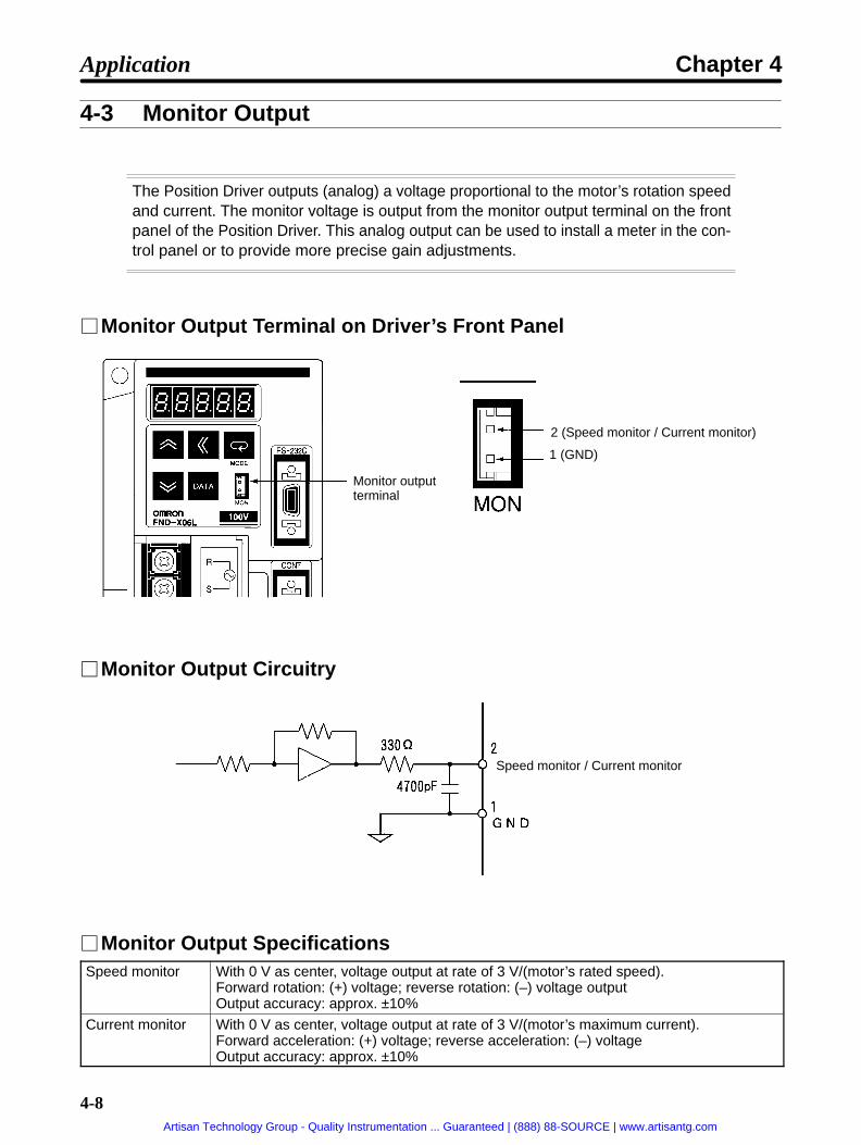
4-8
4-3 Monitor Output
The Position Driver outputs (analog) a voltage proportional to the motor’s rotation speedand current. The monitor voltage is output from the monitor output terminal on the frontpanel of the Position Driver. This analog output can be used to install a meter in the con-trol panel or to provide more precise gain adjustments.
Monitor Output Terminal on Driver’s Front Panel
Monitor outputterminal
2 (Speed monitor / Current monitor)
1 (GND)
Monitor Output Circuitry
Speed monitor / Current monitor
Monitor Output SpecificationsSpeed monitor With 0 V as center, voltage output at rate of 3 V/(motor’s rated speed).
Forward rotation: (+) voltage; reverse rotation: (–) voltage outputOutput accuracy: approx. ±10%
Current monitor With 0 V as center, voltage output at rate of 3 V/(motor’s maximum current). Forward acceleration: (+) voltage; reverse acceleration: (–) voltageOutput accuracy: approx. ±10%
Application Chapter 4
Artisan Technology Group - Quality Instrumentation ... Guaranteed | (888) 88-SOURCE | www.artisantg.com

4-9
User Parameter SettingNo.UP-
Name Min.unit
Settingrange
Factorysetting
Explanation
25 Monitor outputselection
--- 000 to011
010 Specifies the output terminal function.
0
Voltage polarity0: Not reversed1: Reversed
Speed/Current selection0: Current1: Speed
Application Chapter 4
Artisan Technology Group - Quality Instrumentation ... Guaranteed | (888) 88-SOURCE | www.artisantg.com

4-10
4-4 Protection and Diagnosis
4-4-1 AlarmsThe Position Driver has the error detection functions shown below. When an error is detected the outputsignal ALM (CN1-28) turns OFF and the alarm is displayed.
The following table shows the alarm codes that are displayed on the Position Driver’s front panel, and itprovides explanations of each of their meanings.
Display Error detectionfunction
Meaning of code and probable cause Motor current
A.L01 Overcurrent Overcurrent or overheating detected. Servo OFF
A.L02 Overvoltage Main circuit’s DC voltage exceeded410 VDC.
Servo OFF
A.L03 Voltage drop Main circuit’s DC voltage fell below200 VDC.
Servo OFF
A.L06 Resolverdisconnection
The resolver is disconnected. Servo OFF
A.L07 Power status error The main circuit connections are differentfrom the settings.
Servo OFF
A.L09 RegenerationResistor overheat
The internal Regeneration Resistor hasoverheated (only for FND-X50).
Servo OFF
A.L10 Regenerationoperation error
The regeneration transistor has been ON formore than 50 ms (only for FND-X50).
Servo OFF
A.L12 Clock stopped The Position Driver’s clock is stopped. Servo OFF
A.L15 Overcurrent (soft) The current exceeded the motor’s ratedcurrent (120%).
Servo OFF
A.L16 Speed ampsaturation
The speed amp was saturated for more than3 seconds.
Servo OFF
A.L17 Motor overload The electrothermal value exceeded 110%. Servo OFF
A.L18 Short timeoverload
The current exceeded the motor’s ratedcurrent (120%) for a sustained period oftime.
Servo OFF
A.L19 Resolver error There was an error in the resolver feedback. Servo OFF
A.L20 Speed over The motor speed exceeded 120% of themaximum speed.
Servo OFF
A.L21 Deviation counterover
The deviation counter’s accumulated pulsesexceeded ±221.
Servo OFF
A.L26 Parameter settingerror
The user parameter settings (UP-01, UP-02)are not appropriate.
Servo OFF
A.L32 Resolver error The resolver feedback was in error. Servo OFF
A.L34 + Software limitover
The reference value exceeded the softwarelimit in the positive direction (PP-10, PP-11).
Servo-lock
A.L35 – Software limitover
The reference value exceeded the softwarelimit in the negative direction (PP-12,PP-13).
Servo-lock
A.L37 Coordinate counterover
The present value exceeded ±231.Teaching or origin teaching was executedwith the parameter setting exceeded.
Servo-lock
Application Chapter 4
Artisan Technology Group - Quality Instrumentation ... Guaranteed | (888) 88-SOURCE | www.artisantg.com

4-11
Display Motor currentMeaning of code and probable causeError detectionfunction
A.L38 Overrun The limit input signal in the direction ofmovement turned OFF.
Servo OFF
A.L40 Encoderdisconnection
An encoder disconnection or short-circuitwas detected.
Servo OFF
A.L41 Encodercommunicationserror
There was an error in the encoder’sS-phase data (or A-phase when an absoluteencoder is connected).
Servo OFF
A.L42 Absolute encoderbackup error
The absolute encoder’s backup voltagedropped.
Servo OFF
A.L43 Absolute encoderchecksum error
There was an error in the absoluteencoder’s memory data check.
Servo OFF
A.L44 Absolute encoderbattery error
The absolute encoder’s backup batteryvoltage dropped.
Servo OFF
A.L45 Absolute encoderabsolute valueerror
There was an error in the absoluteencoder’s sensor check.
Servo OFF
A.L46 Absolute encoderover speed
The speed exceeded 400 r/min whenmultiple rotation data was transmitted.
Servo OFF
A.L47 Encoder data nottransmitted
The encoder’s S-phase data was nottransmitted within the prescribed time.
Servo OFF
A.L48 Encoderinitialization error
The encoders reception circuitrymalfunctioned.
Servo OFF
A.L50 BCD data error The input data for P.IN0 to 7 is not BCD. Servo-lock
A.L51 Present positionunknown
START, TEACH, or ORIGIN TEACH wasexecuted when the origin was notestablished.
Servo-lock
A.L52 PTP data not set A point number was selected for which thePTP data was not set.
Servo-lock
Application Chapter 4
Artisan Technology Group - Quality Instrumentation ... Guaranteed | (888) 88-SOURCE | www.artisantg.com

4-12
4-4-2 Countermeasures to AlarmsAlarm dis-
playError content Condition when
error occurredProbable cause Countermeasures
A.L01 Overcurrent Occurred whenpower was turnedON.
Control board defective. Replace Driver.
Occurred whenS d
Current feedback circuit error Replace Driver.Servo was turnedON.
Main circuit transistor moduleerror
Servomotor power line isshort-circuited or grounded.
• Correct the power line short-circuiting or grounding.
• Measure the insulationresistance at the Servomo-tor itself. If there is short-cir-cuiting, replace the Servo-motor.
Overheating Occurred duringoperation eventhough power wasON
The ambient temperature forthe Driver is higher than 55°C.
Bring the ambient tempera-ture for the Driver down to55°C or lower.
ON.
If reset is executedafter waiting for atime, operationresumes.
The load torque is too high. • Lighten the load.• Lengthen the acceleration
time.• Select another Servomotor.
A.L02 Overvoltage Occurred whenpower was turnedON.
The power supply voltage isoutside of the allowablerange.
• The supply voltage must be170 to 264 VAC when200 VAC is specified
• The supply voltage must be85 to 127 VAC when100 VAC is specified.
Occurred duringmotor deceleration.
The load inertia is too large. • Lengthen the decelerationtime.
• Calculate the regenerationand select a RegenerationResistor.
The power supply voltage isoutside of the allowablerange.
• The supply voltage must be170 to 264 VAC when200 VAC is specified
• The supply voltage must be85 to 127 VAC when100 VAC is specified.
The external RegenerationResistor is damaged.
Calculate the amount ofregeneration and replace theRegeneration Resistor withone of the appropriate capac-ity.
Occurred whilelowering (verticalshaft).
Gravity torque is too large. • Add a counterbalance to themachine, and reduce thegravity torque.
• Reduce the lowering speed.• Connect an external Regen-
eration Resistor.
Application Chapter 4
Artisan Technology Group - Quality Instrumentation ... Guaranteed | (888) 88-SOURCE | www.artisantg.com

4-13
Alarm dis-play
CountermeasuresProbable causeCondition whenerror occurred
Error content
A.L03 Voltage drop Occurred duringoperation.
The power supply voltage fellbelow the prescribed value.
• For 200-VAC input specifi-cations, use a 170 to264-VAC power supply.
• For 100-VAC input specifi-cations, use an 85 to127-VAC power supply.
Occurred duringmotor acceleration
The power supply capacity isinsufficient.
Increase the power supplycapacity.
A.L06 Resolver discon-nection
Occurred whenpower was turnedON
The UP-02 (applicable motor)setting is wrong.
Set the motor model code cor-rectly.
ON. The resolver’s wiring is dis-connected or faulty.
• Connect any places that aredisconnected.
• Correct the wiring.
Occurred afterslight movement atthe beginning.
There is poor contact at theconnectors.
Make sure the connectors areinserted firmly and locked intoplace.
A.L07 Power statuserror
--- An error occurred in the maincircuit.
Replace the Driver.
A.L09 RegenerationResistor over-heat
Occurred duringoperation.
The regenerative absorptionexceeded the internal absorp-tion.
Connect an external Regen-eration Resistor.
The power supply voltage isoutside the allowable range.
Use a 170 to 264-VAC powersupply.
A.L10 Regenerationoperation error
Occurred duringoperation.
The Regeneration Resistor isdamaged.
• Replace the externalRegeneration Resistor.
• If an external RegenerationResistor is not being used,replace the Driver.
An external RegenerationResistor is not being used andthe short bar has beenremoved from between JP1and JP2 on the terminal block.
Mount a short bar betweenJP1 and JP2.
The regeneration circuit isdamaged.
Replace the Driver.
A.L12 Clock stop --- The Position Driver’s internalclock has stopped.
Replace the Driver.
A.L15 Overcurrent(soft)[Th t
Occurred duringoperation.
The mechanical system islocked.
Correct the places that arelocked.( )
[The currentexceeded themotor’s rated
The power lines are wiredincorrectly.
Correct the wiring.
motor’s ratedcurrent (120%).] The power lines are shorted-
circuited or grounded.Correct the short-circuiting orgrounding.
The UP-02 (applicable motor)setting is wrong.
Set the motor model code cor-rectly.
A.L16 Speed amp satu-ration[Th d
Occurred duringoperation.
The mechanical system islocked.
Correct the places that arelocked.
[The speed ampwas saturated formore than 3
The power lines are wiredincorrectly.
Correct the wiring.
more than 3seconds.] The UP-02 (applicable motor)
setting is wrong.Set the motor model code cor-rectly.
Application Chapter 4
Artisan Technology Group - Quality Instrumentation ... Guaranteed | (888) 88-SOURCE | www.artisantg.com

4-14
Alarm dis-play
CountermeasuresProbable causeCondition whenerror occurred
Error content
A.L17 Motor overload[The electrother-
l l
Occurred duringoperation.
The mechanical system islocked.
Correct the places that arelocked.[
mal valueexceeded 110%.]
The power lines are wiredincorrectly.
Correct the wiring.
The load is too large. • Lighten the load.• Lengthen the deceleration
time.
The gain adjustment is incor-rect.
Re-adjust the gain.
A.L18 Short time over-load[Th t
Occurred duringoperation.
The mechanical system islocked.
Correct the places that arelocked.
[The currentexceeded themotor’s rated
The power lines are wiredincorrectly.
Correct the wiring.
motor’s ratedcurrent (120%)for a sustainedperiod of time.]
The load is too large. • Lighten the load.• Lengthen the deceleration
time.]
The gain adjustment is incor-rect.
Re-adjust the gain.
A.L19 Resolver error[There was anerror in theresolver feed
Occurred duringoperation.
The resolver cable is discon-nected.
• Connect any disconnectedplaces.
• Correct any faulty contacts.resolver feed-back.] Malfunctioning was caused by
noise.Wire the resolver cables sep-arately from the power lines.
A.L20 Speed over[The motor
d d d
The motor oper-ated at high speed
t t
There was a resolver feed-back error.
Wire the resolver cables sep-arately from the power lines.[
speed exceeded120% of themaximum
gupon startup. The encoder is wired incor-
rectly.Correct the wiring.
maximumspeed.] Occurred during
operation.The gain adjustment is incor-rect.
Re-adjust the gain.
A.L21 Deviation counterover[The error count-
’ l t d
Motor did not oper-ate even thoughthe START signal
t d ON
The motor power lines or theencoder lines are wired incor-rectly.
Correct the wiring.
[er’s accumulatedpulses exceeded±221 ]
gwas turned ON. The mechanical system is
locked.Correct the places that arelocked.
±221.]Occurred at high-speed rotation.
The motor power lines or theencoder lines are wired incor-rectly.
Correct the wiring.
Occurred whenpositioning with al t f
The gain adjustment is incor-rect.
Re-adjust the gain.g
large amount ofmovement or dur-ing a JOG opera-
Acceleration was too sudden. Lengthen the accelerationtime.
ing a JOG opera-tion. The load is too large. • Lighten the load.
• Select another motor.
Occurred whenoperating at the
i t ti
The reference speed is toohigh.
Correct the speed settings.g
maximum rotationspeed.
The slip compensation is toolarge.
Correct the slip compensa-tion.
A.L26 Parameter set-ting error
Occurred whenpower was turnedON.
No data is set for UP-01 andUP-02, or else the setting isincorrect.
Correctly set the data forUP-01 and UP-02. (After set-ting the data, turn the poweroff and back ON.)
Application Chapter 4
Artisan Technology Group - Quality Instrumentation ... Guaranteed | (888) 88-SOURCE | www.artisantg.com

4-15
Alarm dis-play
CountermeasuresProbable causeCondition whenerror occurred
Error content
A.L32 Resolver error Occurred whenpower was turnedON
The resolver cable is discon-nected.
Connect any disconnectedplaces.
ON. The resolver cable wiring isincorrect.
Correct the wiring.
The UP-02 (applicable motor)setting is wrong.
Set the motor model code cor-rectly.
A.L34 + Software limitover
Occurred duringoperation.
The reference value set inPP-10 and PP-11 wasexceeded.
• Reset the alarm and useJOG or manual operation torelease from the softwarelimit.
• Correct the reference value.• Correct the PP-10 and
PP-11 values.
A.L35 – Software limitover
Occurred duringoperation.
The reference value set inPP-12 and PP-13 wasexceeded.
• Reset the alarm and useJOG or manual operation torelease from the softwarelimit.
• Correct the reference value.• Correct the PP-12 and
PP-13 values.
A.L37 Coordinatecounter over[Th t
Occurred duringshaft movement.
The reference value is toolarge.
Correct the reference value.
[The presentvalue exceeded±231.]
Feedback control is beingemployed in PTC controlmode.
Correctly set the control mode(UP-01). (After setting thedata, turn the power OFF andback ON.)
A.L38 Overrun[The limit input
Occurred duringshaft movement.
The reference value is toolarge.
Correct the reference value.[signal in thedirection ofmovement turned
The limit sensor’s position isincorrect.
Correct the limit sensor’sposition.
movement turnedOFF during anoperation otherthan origin
Occurred whenbeginning.
The limit sensor’s polarity isincorrect.
Wire the sensor so that itturns ON during normaloperation.than origin
search.] The limit sensor is broken. Replace the limit sensor.
A.L40 Encoder discon-nection
Occurred aftermoving just a little
t th b i i
The encoder’s lines are dis-connected.
Connect any disconnectedplaces.g j
at the beginning. There is poor contact at theconnectors.
Make sure the connectors areinserted firmly and locked intoplace.
The encoder’s wiring is incor-rect.
Correct the wiring.
The encoder is damaged. Replace the motor.
The Driver is damaged. Replace the Driver.
Occurred whenpower was turnedON
The UP-02 (applicable motor)setting is wrong.
Set the motor model code cor-rectly.
ON. The encoder cable is loose. Make sure the connectors areinserted firmly and locked intoplace.
A.L41 Encoder commu-nications error( t 1)
Occurred whenpower was turnedON
The UP-02 (applicable motor)setting is wrong.
Set the motor model code cor-rectly.
(see note 1) ON. The encoder S-phase wiringis incorrect.
Correct the wiring.
Application Chapter 4
Artisan Technology Group - Quality Instrumentation ... Guaranteed | (888) 88-SOURCE | www.artisantg.com

4-16
Alarm dis-play
CountermeasuresProbable causeCondition whenerror occurred
Error content
A.L42 Absolute encoderbackup error
Occurred whenpower was turnedON.
The absolute encoder’sbackup voltage dropped (evenif the encoder was being usedfor the first time).
Perform the absolute encodersetup.
A.L43 Absolute encoderchecksum error
Occurred whenpower was turnedON.
There was an error in theabsolute encoder’s memorydata check.
Perform the absolute encodersetup.
A.L44 Absolute encoderbattery error
Occurred whenpower was turnedON.
The absolute encoder’sbackup battery voltagedropped (to 2.6 to 2.8 Vmax.).
Replace the battery and thenperform the absolute encodersetup.
A.L45 Absolute encoderabsolute valueerror
Occurred whenpower was turnedON.
There was an error in theabsolute encoder’s sensorcheck. (Internal encodererror)
• Turn the power OFF andthen back ON.
• If the error persists, thenreplace the motor.
A.L46 Absolute encoderover speed
Occurred whenpower was turnedON.
The speed exceeded400 r/min when the powerwas turned ON.
Turn ON the power while themotor is stopped
A.L47 Encoder data nottransmitted
Occurred whenpower was turnedON
The UP-02 (applicable motor)setting is wrong.
Set the motor model code cor-rectly.
ON. The encoder S-phase wiringis disconnected.
Connect any disconnectedplaces.
A.L48 Encoder initial-ization error
Occurred whenpower was turnedON.
The Driver malfunctioned. • Turn the power OFF andthen back ON.
• If the error persists, thenreplace the motor.
A.L50 BCD data error Occurred whenpower was turnedON
The data input for direct posi-tioning was not BCD.
Re-input the data and makesure it is correct.
ON. The point number input forpoint positioning was notBCD.
A.L51 Present positionunknown
Occurred at startupor when teaching.
START, TEACH, or ORIGINTEACH was executed whenthe origin was not established.
Execute an origin search toestablish the origin.
A.L52 PTP data not set Occurred whenpower was turnedON.
A point number was selectedfor which the PTP data wasnot set.
• Set the correct PTP data.• Select a point number for
which PTP data has beenset.
Note 1. If the motor has been incorrectly connected, or if the applicable motor (UP-02) has been incor-rectly set, the motor may perform some revolutions before an A.L41 error is generated. Checkthe settings for the connected motor and the applicable motor before recommencing opera-tion.
Note 2. For details on replaceable batteries, refer to 2-2-7 Battery Wiring and Encoder Setup forAbsolute Encoder.
Application Chapter 4
Artisan Technology Group - Quality Instrumentation ... Guaranteed | (888) 88-SOURCE | www.artisantg.com

4-17
4-4-3 CompoBus/S-type Position Driver Protective andDiagnostic Functions
With the CompoBus/S Master Unit (C200HW-SRM21 is used here as an example) andthe CompoBus/S-type Position Driver (FND-X-SRT), the communications status canbe checked using the LED indicators.
FND-X-SRT
Diagnosis Using LED Indicator StatusIndicator status Probable cause of error Countermeasure
PWR COMM ERRNot lit Not lit Not lit The Position Driver’s power is not
turned on.Turn on the power for the PositionDriver.
Lit Not lit Not lit The Slave’s node address is set inthe 8 to 15 range when the maxi-mum number of Slaves connectibleto the Master is 16.
Set the node address from 0 to 7,or set the maximum number of con-nectible Slaves to 32.
Lit Not lit Lit A communications error occurredduring communications.
Establish the cause of the error bychecking the LED indicator on theMaster and take appropriate coun-termeasures.
The Master is a CQM1, and thenumber of occupied points pernode is set to 4.
Change the setting to 8-point mode.
Lit Not lit --- The Master’s power is not turnedon.
Turn on the power for the Master.
CompoBus/S Master Unit (Example: C200HW-SRM21)
Diagnosis Using LED Indicator StatusIndicator Status Meaning
RUN (green) Lit The Position Driver is operating normally.(g )
Not lit Indicates one of the following conditions:The power is OFF, there is an I/O setting error, the CPU Unit is in standbystatus, or there is a unit number setting error.
SD (yellow) Lit Data is being transmitted.(y )
Not lit Data is not being transmitted.RD (yellow) Lit Data is being received.(y )
Not lit Data is not being received.ERC (red) Lit A Slave has been withdrawn from communications.
(Communications error)Not lit The Slaves are communicating normally.
IN/OUT (red) Lit An error has occurred with an Output Slave.( )
Not lit An error has occurred with an Input Slave or all Slaves are operating nor-mally.
8 4 2 1(red)
Lit/Not lit These indicators represent the four-digit binary slave number of the Slavein which the error occurred.
Application Chapter 4
Artisan Technology Group - Quality Instrumentation ... Guaranteed | (888) 88-SOURCE | www.artisantg.com

4-18
4-4-4 Overload CharacteristicsAn overload protection function (electrothermal) is built into the Position Driver to protect against Posi-tion Driver or Servomotor overload. If a motor overload (A.L17) or temporary overload (A.L18) doesoccur, first clear the cause of the error and then wait at least one minute for the Servomotor temperatureto drop before turning ON the power again. If the power is turned ON again too soon, the Servomotor coilmay be damaged.
Motor Overload (A.L17) Detection
Detection Method• A motor overload is detected by first calculating the motor’s heat generation (the electrothermal value)
from the current flowing to the motor.
• If 110% of the electrothermal value is exceeded, a motor overload will be detected.
• The electrothermal value is displayed by the Monitor Mode’s electrothermal value display (oL).
Detection TimeWhen a uniform load is added beginning with an electrothermal value of 0, the time until the Driverdetects a motor overload is as shown in the following diagram. (Reference value)
Note The initial value for the electrothermal value when the Driver is powered up is set at 90%. This isbecause of the need to rapidly detect an overload in order to prevent motor burnout. Therefore athermal value of about 90% will be displayed even when there is no overload to the motor whenthe power is turned ON. As long as there is no overload, however, the electrothermal value will begradually decreased, so there is no problem for operation.
Detection time (min)
Load ratio (%)
Note 1. The load ratio is calculated in relation to the motor’s rated current.
Load ratio (%) =Motor current
Motor rated current× 100
Note 2. The value for “T” is determined individually for each Servomotor model, and indicates themotor’s burn time constant.
Application Chapter 4
Artisan Technology Group - Quality Instrumentation ... Guaranteed | (888) 88-SOURCE | www.artisantg.com

4-19
• U-series (30 to 750 W) Servomotors
Motor model Wattage T (min)R88M-U03030 30 W 4
R88M-U05030 50 W 4
R88M-U10030 100 W 8
R88M-U20030 200 W 8
R88M-U40030 400 W 10
R88M-U75030 750 W 18
• U-UE-series Servomotors
Motor model Wattage T (min)R88M-UE10030 100 W 8
R88M-UE20030 200 W 8
R88M-UE40030 400 W 10
R88M-UE75030 750 W 18
• U-series (1 to 2 kW) Servomotors
Motor model Wattage T (min)R88M-U1K030 1 kW 30
R88M-U1K530 1.5 kW 39
R88M-U2K030 2 kW 45
• H-series Servomotors
Motor model Wattage T (min)R88M-H05030 50 W 6
R88M-H10030 100 W 7
R88M-H20030 200 W 12
R88M-H30030 300 W 15
R88M-H50030 500 W 18
R88M-H75030 750 W 20
R88M-H1K130 1,100 W 22
• M-series Servomotors (1,200 r/min)
Motor model Wattage T (min)R88M-M20012 200 W 19
R88M-M40012 400 W 24
R88M-M70012 700 W 41
R88M-M1K112 1,100 W 37
R88M-M1K412 1,400 W 58
R88M-M1K812 1,800 W 64
Application Chapter 4
Artisan Technology Group - Quality Instrumentation ... Guaranteed | (888) 88-SOURCE | www.artisantg.com

4-20
• M-series Servomotors (2,000 r/min)
Motor model Wattage T (min)R88M-M20020 200 W 14
R88M-M40020 400 W 15
R88M-M70020 700 W 31
R88M-M1K120 1,100 W 38
R88M-M1K820 1,800 W 53
R88M-M2K220 2,200 W 54
• M-series Servomotors (4,000 r/min)
Motor model Wattage T (min)R88M-M06040 60 W 7
R88M-M12040 120 W 11
R88M-M20040 200 W 7
R88M-M40040 400 W 17
R88M-M70040 700 W 34
R88M-M1K140 1,100 W 21
R88M-M1K040 2,000 W 36
Short Time Overload (A.L18) Detection
Detection MethodA temporary overload is detected when the motor’s current continually exceeds 120% of the motor’srated current for at least a fixed period of time.
Detection TimeThe detection time is as shown in the following diagram. It is the same for all Servomotor models. (Ref-erence value)
Detection time (s)
Load ratio (%)
Application Chapter 4
Artisan Technology Group - Quality Instrumentation ... Guaranteed | (888) 88-SOURCE | www.artisantg.com

4-21
4-4-5 Alarm OutputThis chapter describes the timing of alarm outputs when power is turned ON and when alarms occur.The method used to clear alarms is also described.
Timing Chart
2 ms min.
2 ms max.
Approx. 40 ms
Approx. 2 s
Approx. 110 ms
Power input(R, S)
RUNcommand(RUN)
Erroroccurrence
Alarm reset(RESET)
Alarm output(ALM)
Power tomotor
ON
OFF
ON
OFF
ON
OFF
ON
OFF
ON
OFF
Error
Alarm Output Circuitry (DIO Type)
Alarm output28
19 OGND
Output specifications: 24 VDC, 40 mA max.Normal: Output transistor ONError (alarm): Output transistor OFF
Clearing Alarms• Any of the following methods can be used to clear alarms:
Turn ON the alarm reset signal (RESET).Turn the power supply OFF and then back ON.Press the Data Key while the alarm is displayed.
Power status alarms (A.L07), however, cannot be cleared by turning the power OFF and then backON.
• Operation will start as soon as the alarm is cleared if the alarm is cleared while the RUN command(RUN) is ON, possibly creating a dangerous situation. Turn OFF the RUN command before clearingalarms.
Application Chapter 4
Artisan Technology Group - Quality Instrumentation ... Guaranteed | (888) 88-SOURCE | www.artisantg.com

4-22
4-5 Troubleshooting
4-5-1 Preliminary Inspection
This section describes the preliminary inspections and monitoring devices that arerequired to locate and clear the cause of an error.
Power Supply Voltage Check• Check that the voltage at the AC power supply terminals is within the following range:
100-VAC-input type 85 to 127 VAC200-VAC-input type 170 to 264 VAC
If the voltage is outside this range, faulty operation may occur. Provide the correct power supply.
• Check that the power supply voltages for external device interfaces are within the following range:23 to 25 VDC
If the voltage is outside this range, faulty operation may occur. Provide the correct power supply.
Monitoring Device Selection
Alarm CheckIf an alarm has been generated, check the alarm code and take countermeasures in accordancewith the meaning of that code.
If an alarm has not been generated, take countermeasures in accordance with the nature of theerror. (Refer to 4-5-4 Troubleshooting.)
Monitoring Device TypeThe following types of monitoring device are available.
Position Driver Display PanelInvestigate the error using the 7-segment LED display panel on the front side of the Position Driveralong with the operating keys. (When an alarm has been generated, it will automatically be dis-played.) The investigation procedure for this device type is explained in this manual.
Teaching BoxUse the following three items together. (When an alarm has been generated, it will automatically bedisplayed.)
CVM1-PRO01 Programming Console without ROM.
CVM1-MP702 Memory Cassette compatible with FND-X and MC/NC Units, orCVM1-MP703 FND-X-dedicated Memory Cassette.
CV500-CN2A Connecting Cable to connect the Position Driver and the Teaching Box.(The in the model name represents the length of the cable. Any of the lengths 2, 4, or 6 m can beused.)
Application Chapter 4
Artisan Technology Group - Quality Instrumentation ... Guaranteed | (888) 88-SOURCE | www.artisantg.com

4-23
For details on the operating procedures for this device type, refer to the Teaching Box (For PositionDrivers) Operating Manual (W354).
4-5-2 Precautions
When performing checks of the inputs and outputs following error generation, there is apossibility that the Position Driver will operate unexpectedly or suddenly stop. Be sure totake the following precautions. Do not perform any operations or procedures notdescribed in this manual.
Precautions• When checking for breaks in cables be sure to disconnect the wiring first. With the wiring is connected,
there is still a possibility of continuity caused by a return circuit, even if a continuity check is performed.
• If the encoder signal goes out, the Motor will run out of control, and an error will be generated. Wheninvestigating the encoder signal, remove the Motor from the mechanical system first.
• When measuring output from the encoder, take the measurement at E0V (0-V encoder power supply)as a basis. By measuring the differential between CH1 and CH2 with an oscilloscope, the effects ofnoise can be offset.
• Before performing checks, ensure that nobody is inside the mechanical equipment, and that if theMotor runs out of control, no damage will be caused. Also, in preparation for the unlikely event of theMotor running out of control, before performing checks for errors, first check that an emergency stopcan be performed for the machinery.
4-5-3 Replacing the Position Driver and the Motor
Use the following procedure to replace the Position Driver or Motor.
Replacing the FND-X Position Driver1. Make a copy of the Position Driver parameters.
Using the Position Driver operation keys, display all of the parameters and create a written recordof them. (Refer to 7-2 Parameter Settings Tables.)
2. Replace the Position Driver.
With the CompoBus/S-type, set the communications unit number switch to the original FND-X set-ting.
3. Set the Position Driver parameters.
With Personal Computer Monitoring Software:Using the Personal Computer Monitoring Software, transfer all the parameters saved at the per-sonal computer to the Position Driver.
Without Personal Computer Monitoring Software:Using the Position Driver operation keys, recreate all the parameter settings recorded in step 1.
4. Perform origin teaching.
If there is no origin compensation because, for example, the backup copy of the parameters wasmade at the design stage, it will be necessary to perform origin teaching.Use the following procedure to perform origin teaching.
Application Chapter 4
Artisan Technology Group - Quality Instrumentation ... Guaranteed | (888) 88-SOURCE | www.artisantg.com
4-24
Procedure for Origin Teaching
a) After replacement, perform origin search with the new Position Driver.
b) Move to the original position of the origin by moving the mechanical system by hand in a servo-free state, or by moving the mechanical system using JOG operations.
c) Turn OFF the Position Driver run command (RUN), and after turning the origin search input(SEARCH) ON, turn ON the teaching input (TEACH).
d) Check that the teaching completed output (T.COM) turns ON. An origin compensation thatmakes the present position of the system into the position of the origin, will be registered in thePosition Driver.
Replacing the Motor1. Replace the Motor.
2. Perform origin teaching.
When the Motor is replaced, the Motor’s own origin position (Z phase) will shift, making it neces-sary to perform origin teaching.
Procedure for Origin Teaching
a) After replacement, perform origin search.
b) Move to the original position of the origin by moving the mechanical system by hand in a servo-free state, or by moving the mechanical system using JOG operations.
c) Turn OFF the Position Driver run command (RUN), and after turning the origin search input(SEARCH) ON, turn ON the teaching input (TEACH).
d) Check that the teaching completed output (T.COM) turns ON. An origin compensation thatmakes the present position of the system into the position of the origin, will be registered in thePosition Driver.
Application Chapter 4
Artisan Technology Group - Quality Instrumentation ... Guaranteed | (888) 88-SOURCE | www.artisantg.com

4-25
4-5-4 Troubleshooting
When an error occurs, check the error contents by means of the operating status andalarm display, investigate the cause and apply the appropriate countermeasures.
Error Diagnosis by Means of Operating Status (DIO, CompoBus/S)Symptom Probable cause Items to check Countermeasures
The LED indi-cator does notlight even whenthe power sup-
Power supply lines are improp-erly connected.
Check the power supply volt-age.
Correct the power supply.
the power sup-ply is turnedON.
Check the power supply lines. Correct the wiring.
Application Chapter 4
Artisan Technology Group - Quality Instrumentation ... Guaranteed | (888) 88-SOURCE | www.artisantg.com

4-26
Symptom CountermeasuresItems to checkProbable causeThe motor doesnot operateeven when theSTART
The RUN signal is OFF. Use the Check Mode to checkthe RUN signal’s ON/OFF sta-tus.
• Input the RUN signal.• Correct the wiring.
START com-mand is input.
The correspondence betweenthe Driver and the Servomotor isincorrect.
Check the models. Combine models that corre-spond correctly.
The CWL/CCWL inputs areOFF.
Use the Check Mode to checkthe inputs.
Correct the wiring.
The software limit is beingdetected.
Use the Monitor Mode to checkthe present value.
Correctly set the software limits.
Check the software limits(PP-10, 11, 12, 13).
Deceleration stop is OFF. Use the Check Mode to checkthe input.
DIO type:
• Correct the wiring.
CompoBus/S type:
• Turn both the external controlinput (CN4-4) and the Compo-Bus/S input (OUT7) ON.
• Correct the wiring.
The point number input is 0. Use the Check Mode to checkthe input.
Correctly set the point numberinput.
One of the following signals isbeing input: origin search,teaching, JOG, or alarm reset.
Use the Check Mode to checkthe inputs.
Correct the wiring.
During direct positioning, theposition data is set for “I (incre-mental) 0.”
Check the position data setting. Correctly set the position data.
The position data (Pd) to beexecuted does not match thepresent value.
Check the position data(Pd).
Correctly set the position data(Pd).
The motor’s power lines are dis-connected.
Check the power lines. Correct the wiring.
The control mode is incorrect. Check the control mode(UP-01).
Correctly set the control mode.
The START signal is not beinginput.
Use the Check Mode to checkthe input.
Correct the wiring.
During direct positioning, thepositioning data is not being
l i d
Check the wiring for the positionand speed data selections.
Correct the wiring.g g
properly received. Check the setting of the signaloutput time (PP-26).
Check the signal reception tim-ing and correctly set the pulsewidth.
Reference speed (PP-14, 15) is“0.”
Check the reference speed(PP-14, 15) setting.
Correctly set the referencespeed (PP-14, 15).
The rotationdirection is
The motor rotation direction(UP-26) setting is incorrect.
Check the motor rotation direc-tion (UP-26) setting.
Correctly set the motor rotationdirection (UP-26)
wrong. The position data (Pd) set-ting is incorrect.
Check the position data(Pd) setting.
Correctly set the position data(Pd).
During direct positioning, theposition data’s polarity input isincorrect.
Check the position data setting. Correctly set the position data.
The encoder/resolver wiring isincorrect.
Check the encoder/resolver wir-ing.
Correct the wiring.
Application Chapter 4
Artisan Technology Group - Quality Instrumentation ... Guaranteed | (888) 88-SOURCE | www.artisantg.com

4-27
Symptom CountermeasuresItems to checkProbable causeThe position isslipping.
The point number input is incor-rect.
Use the Check Mode to checkthe point number input.
Correctly set the point numberinput.g
The position data (Pd) set-ting is incorrect.
Check the position data(Pd) setting.
Correctly set the position data(Pd).
The minimum setting unit(PP-01) or pulse rate (PP-02,03) setting is incorrect.
Check the minimum setting unit(PP-01) and pulse rate (PP-02,03) settings.
Correctly set the minimum set-ting unit and pulse rate settings.
The compensation (PP-08, 09)setting is incorrect.
Check the compensation(PP-08, 09) setting.
Correctly set the compensation(PP-08, 09).
Dedicated lines are not beingused for the encoder/resolver.
Check the encoder/resolverlines.
Replace the encoder/resolverlines with dedicated lines.
The operation mode for thepoint number being executed isincorrect.
Check the operation mode(Pdr) setting.
Correctly set the operationmode (Pdr).
The coupling connecting themotor shaft to the mechanicalsystem is loose.
Check the mechanical system. Check and adjust the machin-ery.
The belt is loose.
During an origin search, themotor sensor’s Z-phase positionand the origin proximity OFFposition are too close.
Repeat the origin search andcheck whether the search com-pletion position is different.
Disconnect the motor from themechanical system and shift theZ-phase position by the amountshown below. Then reinstall themotor.
U Series: 1/2 revolutionH Series: 1/2 revolutionM Series: 1/4 revolution
The motorstops during
ti
The deceleration stop (STOP)input turned OFF.
Use the Check Mode to checkthe input.
Correct the wiring.g
operation. The alarm reset (RESET) inputturned ON.
Use the Check Mode to checkthe input.
Correct the wiring.
The CWL/CCWL input turnedOFF (when the alarm selection(PP-25) is 0).
Use the Check Mode to checkthe input.
• Correctly set the position data.• Correct the wiring.
The software limit is beingdetected (when the alarm selec-ti (PP 25) i 0)
Use the Monitor Mode to checkthe present position.
Correctly set the position data.(
tion (PP-25) is 0). Check the software limits(PP-10, 11, 12, 13).
Correctly set the software limits.
The motoroperates
t il
The applicable motor (UP-02)setting is incorrect.
Check the applicable motor(UP-02) setting.
Correctly set the applicablemotor (UP-02).
momentarily,but then it stopsoperating.
The motor’s power lines and theencoder/resolver lines are wiredincorrectly.
Check the wiring of the motor’spower lines and the encoder/re-solver lines.
Correct the wiring.
Motor operationis unstable.
The motor’s power lines and theencoder/resolver lines are wiredincorrectly.
Check the wiring of the motor’spower lines and the encoder/re-solver lines.
Correct the wiring.
The coupling connecting themotor shaft to the mechanicalsystem is eccentric, and screwsmay be loose.
Check the mechanical system.Rotate the motor with no load(disconnected from the mechan-ical system).
Check and adjust the machin-ery.
Gain is wrong. --- • Use auto-tuning.• Adjust the gain manually.
Application Chapter 4
Artisan Technology Group - Quality Instrumentation ... Guaranteed | (888) 88-SOURCE | www.artisantg.com

4-28
Symptom CountermeasuresItems to checkProbable causeMotor is over-heating.
The ambient temperature is toohigh.
Check to be sure that the ambi-ent temperature around themotor is no higher than 40°C.
Lower the ambient temperatureto 40°C or lower. (Use a cooleror fan.)
The ventilation is obstructed. Check to see whether anythingis blocking ventilation.
Ensure adequate ventilation.
There is an overload. Use the Monitor Mode to checkthe electrothermal value.
• Lighten the load.• Change to a larger capacity
motor.
There areunusual noises.
The machinery is vibrating. Inspect the machinery to seewhether there are any foreignobjects in the movable parts, orwhether there is any damage,deformation, or looseness.
Fix any problems causing vibra-tion.
The speed loop gain adjustmentis insufficient.
--- • Use auto-tuning.• Adjust the gain manually.
The parameterscannot bechanged.
The parameters are write-pro-tected.
Check the computer’smonitoring software.
Using the computer’s monitoringsoftware, release the writeprotection.
Output torque isinsufficient
The motor has only made smallmovements (approx. ±6 pulsesof encoder resolution) from thepower supply position.
--- After making the motor performrotations of over ±6 pulses,re-attempt normal operation.
Application Chapter 4
Artisan Technology Group - Quality Instrumentation ... Guaranteed | (888) 88-SOURCE | www.artisantg.com

4-29
Error Diagnosis by Means of Operating Status (CompoBus/S Only)Symptom Probable cause Items to check Countermeasures
There is an error in the com-munications data.
The node address is over-lapping another nodeaddress.
Check the node addresssettings of all the Slaves.
Correctly set the nodeaddresses.
The Programmable Control-ler’s load shutdown bit hasturned ON.
Check the status of the Pro-grammable Controller’s loadshutdown bit.
Turn OFF the load shut-down bit.
The communications cableconnection or the commu-nications cable itself isf lt
Check the connections. (If aflat cable is being used,check the connector area.)
Connect the cable properly.
faulty. Check the connectors. Replace the connectors ifnecessary.
Check the conductivity ofthe communications cable.
Replace the cable if neces-sary.
There is no terminatingresistance connected, or itis connected at some posi-tion other than the farthestUnit.
Check the location of theterminating resistance.
Connect the terminatingresistance at the last Unit.
The Master Unit is not con-nected at the end of themain line.
Check the location of theMaster Unit.
Connect the Master Unit atthe end of the main line.
The length of the main line,a branch line, or the totallength is greater than theprescribed limit.
Check the lengths of themain and branch lines, andthe total combined length.
Correct the wiring so thatthe lengths of the main andbranch lines, and the totalcombined length, are withinthe prescribed limits.
VCTF cable is combinedwith special flat cable.
Check the cables that arebeing used.
Use either VCTF or flatcable, but not both together.
Communications will notstart.
The Master is for a CQM1System, and the Program-mable Controller occupieseither two or four words,and a node address is setwhich is not permitted fornodes 0 to 7. (An “addressover” error is generated.)
Check the number of wordsoccupied by the MasterUnit’s Programmable Con-troller, and the number ofpoints occupied per nodeaddress.
Change the number ofwords occupied by the Pro-grammable Controller andthe number of points occu-pied per node address.
Note If a communications error occurs, refer to the operation manual for the Master Unit.
Application Chapter 4
Artisan Technology Group - Quality Instrumentation ... Guaranteed | (888) 88-SOURCE | www.artisantg.com
!
!
4-30
4-6 Periodic Maintenance
WARNING Do not attempt to take the Unit apart or repair. Doing either of these may result inelectrical shock or injury.
Caution Resume operation only after transferring to the new Unit the contents of the datarequired for operation. Not doing so may result in equipment damage.
Servomotors and Position Drivers contain many components and will operate properlyonly when each of the individual components is operating properly. Some of the electri-cal and mechanical components require maintenance depending on application condi-tions. In order to ensure proper long-term operation of Servomotors and Position Driv-ers, periodic inspection and part replacement is required according to the service life ofthe components.
The periodic maintenance cycle depends on the installation environment and application conditions ofthe Servomotor or Position Driver. Recommended maintenance times are listed below for Servomotorsand Position Drivers. Use these as references in determining actual maintenance schedules.
Servomotors• Recommended Periodic Maintenance
Oil Seal: 2,000 hoursBearings: 20,000 hours (U Series); 30,000 hours (H Series, M Series)
Application Conditions: Ambient motor operating temperature of 40C, within allowable shaft load,rated operation (rated torque and r/m), installed as described in operationmanual.
• The radial loads during operation (rotation) on timing pulleys and other components contacting belts istwice the still load. Consult with the belt and pulley manufacturers and adjust designs and system set-tings so that the allowable shaft load is not exceeded even during operation. If a motor is used under ashaft load exceeding the allowable limit, the motor shaft can break, the bearings can burn out, andother problems can occur.
Position Drivers• Recommended Periodic Maintenance
Aluminum analytical capacitors: 50,000 hours at ambient temperature of 35CFans: 55,000 hours at ambient temperature of 20C
(FND-X50H- only)
Application Conditions: Rated operation (rated torque) and installation as described in the User’sManual.
• The life of aluminum analytical capacitors is greatly affected by the ambient operating temperature.Generally speaking, an increase of 10C in the ambient operating temperature will reduce capacitorlife by 50%. We recommend that ambient operating temperature be lowered and the power supplytime be reduced as much as possible to lengthen the maintenance times for Position Drivers.
• It is recommended that the Position Driver be inspected at five-year intervals if they are used underconditions worse than the above or not used over a long time of time. Contact your OMRON represen-tative for inspection and the necessity of any component replacement.
Application Chapter 4
Artisan Technology Group - Quality Instrumentation ... Guaranteed | (888) 88-SOURCE | www.artisantg.com

4-31
Lithium Battery• When using a U-series Servomotor with absolute encoder, periodic maintenance will be required for
the lithium battery. For details about battery lifetimes and replacement methods, refer to 2-2-7 BatteryWiring and Encoder Setup for Absolute Encoder.
Application Chapter 4
Artisan Technology Group - Quality Instrumentation ... Guaranteed | (888) 88-SOURCE | www.artisantg.com

Chapter 5
Specifications
5-1 Position Driver Specifications
5-2 Servomotor Specifications
5-3 Cable Specifications
5
Artisan Technology Group - Quality Instrumentation ... Guaranteed | (888) 88-SOURCE | www.artisantg.com

5-2
5-1 Position Driver Specifications
5-1-1 General Specifications (Common to DIO, CompoBus/S)Item Specifications
Power supply voltage Single-phase 200-VAC (FND-X06H/-X12H/-X25H-):Single-phase 200/240 VAC, –15% to +10%, at 50/60 Hz
Three-phase 200-VAC (FND-X50H-):Three-phase 200/240 VAC, –15% to +10%, at 50/60 Hz
Single-phase 100-VAC (FND-X06L/-X12L-):Single-phase 100/115 VAC, –15% to +10%, at 50/60 Hz
Ambient operating temperature 0 to 55°CAmbient operating humidity 35% to 90% RH (with no condensation)
Ambient storage temperature –10 to 70°CAmbient storage humidity 35% to 90% RH (with no condensation)
Storage and operating atmo-sphere
No corrosive gasses.
Dielectric strength 1,500 VACRMS for 1 min at 50/60 Hz
Insulation resistance Between supply input terminals and case: 5 MΩ min. (at 500 VDC)
Vibration resistance 10 to 150 Hz in X, Y, and Z directions with 0.10-mm double amplitude;acceleration: 9.8 m/s2 1 G max.; time coefficient: 8 min; 4 sweeps
Impact resistance Acceleration 98 m/s2 10 G max., in X, Y, and Z directions, three timeseach.
Protective structure Built into panel (IP00).
Low-voltage Directives applica-ble class
Overvoltage category IIPollution degree II
Note 1. The above items reflect individual evaluation testing. The results may differ under com-pounded conditions.
Note 2. Absolutely do not conduct a withstand voltage test or a megger test on the Position Driver. Ifsuch tests are conducted, internal elements may be damaged.
Note 3. Depending on the operating conditions, some Position Driver parts will require maintenance.Refer to 4-6 Periodic Maintenance for details.
Note 4. The service life of the Position Driver is 50,000 hours at an average ambient temperature of35°C (at the rated torque and the rated rotation speed).
Specifications Chapter 5
Artisan Technology Group - Quality Instrumentation ... Guaranteed | (888) 88-SOURCE | www.artisantg.com

5-3
5-1-2 Performance Specifications
DIO Position Drivers
Item FND-X06L FND-X12L FND-X06H FND-X12H FND-X25H FND-X50H
Continuous output current(0-P)
2.0 A 3.0 A 2.0 A 4.8 A 8.0 A 20 A
Momentary maximum outputcurrent (0-P)
6.0 A 12 A 6.0 A 12 A 25 A 50 A
Input powersupply
Main circuit Single-phase 100/115 VAC(85 to 127 V) 50/60 Hz(The main circuit andcontrol circuits use thesame terminals.)
Single-phase 200/240 VAC (170 to 264 V)50/60 Hz(The main circuit and control circuits usethe same terminals.)
Three-phase200/240 VAC(170 to264 V)50/60 Hz
Controlcircuits
)
Single-phase200/240 VAC(170 to264 V)50/60 Hz
Position/speedf db k
U Series(INC)
30 to 750 W: Optical Incremental encoder, 2,048 pulses/revolution1 to 2 kW: Optical Incremental encoder, 4,096 pulses/revolution
feedback U Series(ABS)
30 to 750 W: Optical Absolute encoder, 1,024 pulses/revolution1 to 2 kW: Optical Absolute encoder, 8,192 pulses/revolution
U-UE Series Optical Incremental encoder, 1,024 pulses/revolution
H Series Magnetic Incremental encoder, 2,000 pulses/revolution
M Series Resolver, absolute accuracy 0.18° max.; ambient temperature 25°Applicableload inertia(See note 1.)
U Series(INC)
Maximum of 30 timesmotor’s rotor inertia
Maximum of 30 timesmotor’s rotor inertia
Maximum of20 timesmotor’s rotorinertia(10 times for1-kW model)
Maximum of10 timesmotor’s rotorinertia
U Series(ABS)
Maximum of 20 timesmotor’s rotor inertia
Maximum of 20 timesmotor’s rotor inertia
Maximum of18 timesmotor’s rotorinertia(10 times for1-kW model)
Maximum of10 timesmotor’s rotorinertia
U-UE Series Maximum of 30 timesmotor’s rotor inertia
Maximum of 30 timesmotor’s rotor inertia
Maximum of20 timesmotor’s rotorinertia
---
H Series Maximum of 10 times motor’s rotor inertia
M Series Maximum of 10 times motor’s rotor inertia
Inverter method PWM method based on IGBT
PWM frequency 10 kHz
Weight Approx. 1.5 kg Approx. 1.5 kg Approx.2.5 kg
Approx.4.5 kg
Frequency response (speedcontrol)
100 Hz (at a load inertia equivalent to motor’s rotor inertia)
Position loop gain 1 to 200 (rad/s)
Feed forward 0% to 200% of speed reference
Pulse rate 1/32,767 (pulse rate 1 / pulse rate 2) 32,767/1
Specifications Chapter 5
Artisan Technology Group - Quality Instrumentation ... Guaranteed | (888) 88-SOURCE | www.artisantg.com
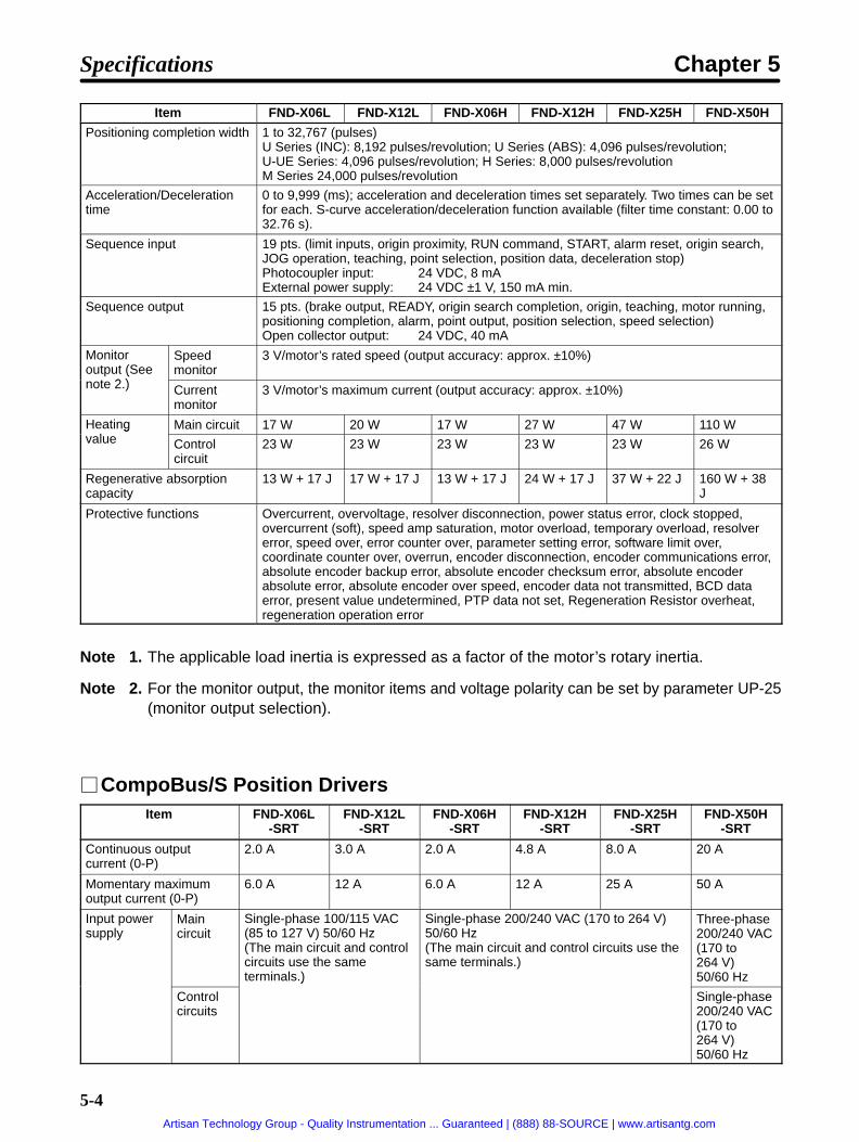
5-4
Item FND-X50HFND-X25HFND-X12HFND-X06HFND-X12LFND-X06L
Positioning completion width 1 to 32,767 (pulses)U Series (INC): 8,192 pulses/revolution; U Series (ABS): 4,096 pulses/revolution;U-UE Series: 4,096 pulses/revolution; H Series: 8,000 pulses/revolutionM Series 24,000 pulses/revolution
Acceleration/Decelerationtime
0 to 9,999 (ms); acceleration and deceleration times set separately. Two times can be setfor each. S-curve acceleration/deceleration function available (filter time constant: 0.00 to32.76 s).
Sequence input 19 pts. (limit inputs, origin proximity, RUN command, START, alarm reset, origin search,JOG operation, teaching, point selection, position data, deceleration stop)Photocoupler input: 24 VDC, 8 mAExternal power supply: 24 VDC ±1 V, 150 mA min.
Sequence output 15 pts. (brake output, READY, origin search completion, origin, teaching, motor running,positioning completion, alarm, point output, position selection, speed selection)Open collector output: 24 VDC, 40 mA
Monitoroutput (See
t 2 )
Speedmonitor
3 V/motor’s rated speed (output accuracy: approx. ±10%)(
note 2.) Currentmonitor
3 V/motor’s maximum current (output accuracy: approx. ±10%)
Heatingl
Main circuit 17 W 20 W 17 W 27 W 47 W 110 Wgvalue Control
circuit23 W 23 W 23 W 23 W 23 W 26 W
Regenerative absorptioncapacity
13 W + 17 J 17 W + 17 J 13 W + 17 J 24 W + 17 J 37 W + 22 J 160 W + 38J
Protective functions Overcurrent, overvoltage, resolver disconnection, power status error, clock stopped,overcurrent (soft), speed amp saturation, motor overload, temporary overload, resolvererror, speed over, error counter over, parameter setting error, software limit over,coordinate counter over, overrun, encoder disconnection, encoder communications error,absolute encoder backup error, absolute encoder checksum error, absolute encoderabsolute error, absolute encoder over speed, encoder data not transmitted, BCD dataerror, present value undetermined, PTP data not set, Regeneration Resistor overheat,regeneration operation error
Note 1. The applicable load inertia is expressed as a factor of the motor’s rotary inertia.
Note 2. For the monitor output, the monitor items and voltage polarity can be set by parameter UP-25(monitor output selection).
CompoBus/S Position DriversItem FND-X06L
-SRTFND-X12L
-SRTFND-X06H
-SRTFND-X12H
-SRTFND-X25H
-SRTFND-X50H
-SRT
Continuous outputcurrent (0-P)
2.0 A 3.0 A 2.0 A 4.8 A 8.0 A 20 A
Momentary maximumoutput current (0-P)
6.0 A 12 A 6.0 A 12 A 25 A 50 A
Input powersupply
Maincircuit
Single-phase 100/115 VAC(85 to 127 V) 50/60 Hz(The main circuit and controlcircuits use the sameterminals.)
Single-phase 200/240 VAC (170 to 264 V)50/60 Hz(The main circuit and control circuits use thesame terminals.)
Three-phase200/240 VAC(170 to264 V)50/60 Hz
Controlcircuits
)
Single-phase200/240 VAC(170 to264 V)50/60 Hz
Specifications Chapter 5
Artisan Technology Group - Quality Instrumentation ... Guaranteed | (888) 88-SOURCE | www.artisantg.com

5-5
Item FND-X50H-SRT
FND-X25H-SRT
FND-X12H-SRT
FND-X06H-SRT
FND-X12L-SRT
FND-X06L-SRT
Position/speed feed-b k
U Series(INC)
30 to 750 W: Optical Incremental encoder, 2,048 pulses/revolution1 to 2 kW: Optical Incremental encoder, 4,096 pulses/revolution
back U Series(ABS)
30 to 750 W: Optical Absolute encoder, 1,024 pulses/revolution1 to 2 kW: Optical Absolute encoder, 8,192 pulses/revolution
U-UESeries
Optical Incremental encoder, 1,024 pulses/revolution
H Series Magnetic incremental encoder, 2,000 pulses/revolution
M Series Resolver, absolute accuracy 0.18° max.; ambient temperature 25°Applicableload inertia(See note 1.)
U Series(INC)
Maximum of 30 timesmotor’s rotor inertia
Maximum of 30 timesmotor’s rotor inertia
Maximum of20 timesmotor’s rotorinertia(10 times for1-kW model)
Maximum of10 timesmotor’s rotorinertia
U Series(ABS)
Maximum of 20 timesmotor’s rotor inertia
Maximum of 20 timesmotor’s rotor inertia
Maximum of18 timesmotor’s rotorinertia(10 times for1-kW model)
Maximum of10 timesmotor’s rotorinertia
U-UESeries
Maximum of 30 timesmotor’s rotor inertia
Maximum of 30 timesmotor’s rotor inertia
Maximum of20 timesmotor’s rotorinertia
---
H Series Maximum of 10 times motor’s rotor inertia
M Series Maximum of 10 times motor’s rotor inertia
Inverter method PWM method based on IGBT
PWM frequency 10 kHz
Weight Approx. 1.5 kg Approx. 1.5 kg Approx.2.5 kg
Approx.4.5 kg
Frequency response(speed control)
100 Hz (at a load inertia equivalent to motor’s rotor inertia)
Position loop gain 1 to 200 (rad/s)
Feed forward 0% to 200% of speed reference
Pulse rate 1/32,767 (pulse rate 1 / pulse rate 2) 32,767/1
Positioning completionwidth
1 to 32,767 (pulses)U Series (INC): 8,192 pulses/revolution; U Series (ABS): 4,096 pulses/revolution; UE Series:4,096 pulses/revolution; H Series: 8,000 pulses/revolutionM Series 24,000 pulses/revolution
Acceleration/Deceleration time
0 to 9,999 (ms); acceleration and deceleration times set separately. Two times can be set foreach. S-curve acceleration/deceleration function available (filter time constant: 0.00 to 32.76s).
CompoBus/S 16 input points (RUN command, start, alarm reset, origin search, JOG operation, inching,point selection, position data, deceleration stop)16 output points (brake output, ready, origin search completed, origin, teaching completed,motor running, positioning completed, alarm, point output, position/speed data selection)
Sequence input 4 pts. (limit inputs, origin proximity, deceleration stop)Photocoupler input: 24 VDC, 8 mAExternal power supply: 24 VDC ±1 V, 40 mA min.
Sequence output 1 pt. (brake output)Open collector output: 24 VDC, 40 mA
Monitoroutput (See
t 2 )
Speedmonitor
3 V/motor’s rated speed (output accuracy: approx. ±10%)(
note 2.) Currentmonitor
3 V/motor’s maximum current (output accuracy: approx. ±10%)
Specifications Chapter 5
Artisan Technology Group - Quality Instrumentation ... Guaranteed | (888) 88-SOURCE | www.artisantg.com

5-6
Item FND-X50H-SRT
FND-X25H-SRT
FND-X12H-SRT
FND-X06H-SRT
FND-X12L-SRT
FND-X06L-SRT
Heatingvalue
Maincircuit
17 W 20 W 17 W 27 W 47 W 110 W
Controlcircuit
23 W 23 W 23 W 23 W 23 W 26 W
Regenerative absorptioncapacity
13 W + 17 J 17 W + 17 J 13 W + 17 J 24 W + 17 J 37 W + 22 J 160 W + 38 J
Protective functions Overcurrent, overvoltage, resolver disconnection, power status error, clock stopped,overcurrent (soft), speed amp saturation, motor overload, temporary overload, resolvererror, speed over, error counter over, parameter setting error, software limit over, coordinatecounter over, overrun, encoder disconnection, encoder communications error, absoluteencoder backup error, absolute encoder checksum error, absolute encoder absolute error,absolute encoder over speed, encoder data not transmitted, BCD data error, present valueundetermined, PTP data not set, CompoBus/S communications error, RegenerationResistor overheat, regeneration operation error
Note 1. The applicable load inertia is expressed as a factor of the motor’s rotary inertia.
Note 2. For the monitor output, the monitor items and voltage polarity can be set by parameter UP-25(monitor output selection).
5-1-3 I/O Specifications
Terminal Blocks (FND-X06/-X12/-X25 )Signal Function Condition
RS
Power supplyinput
These are the application power supply input terminals for the main circuitand control circuit. Pay attention to the power supply voltage, because it va-ries according to the model.FND-XH-: Single-phase 200/240 VAC (170 to 264 VAC) 50/60 HzFND-XL-: Single-phase 100/115 VAC (85 to 127 VAC) 50/60 Hz
PJ
Main circuit DCoutputRegeneration Re-sistor connectionterminal
These are the connection terminals for the Regeneration Resistor(R88A-RR20030/-RR40030). Connect them when the regeneration energy ishigh.
N Main circuit DCoutput
This is the main circuit DC output terminal.
A Servomotor’s A-phase and U-phase output
Red These are the terminals for outputs to the Servomotor. Be careful towire them correctly. OMNUC Servomotors can be connected tothese terminals with R88A-CAU Cable (for U/U-UE-series Servo-
) C C (f S ) O OB Servomotor’s B-phase and V-phase output
White
(motors) or R88A-CAH Cable (for H-series Servomotors). OMRONdoes not provide a dedicated cable to connect these terminals toOMNUC M-series Servomotors, so the user must provide an ap-propriate cable if an M series Servomotor is used
C Servomotor’s C-phase and W-phase output
Blueorblack
propriate cable if an M-series Servomotor is used.
Frame ground Green This is the connection terminal. Use at lease a class-3 ground(100 Ω or less). This ground is used in common for Servomotor out-put and power supply input.
Specifications Chapter 5
Artisan Technology Group - Quality Instrumentation ... Guaranteed | (888) 88-SOURCE | www.artisantg.com
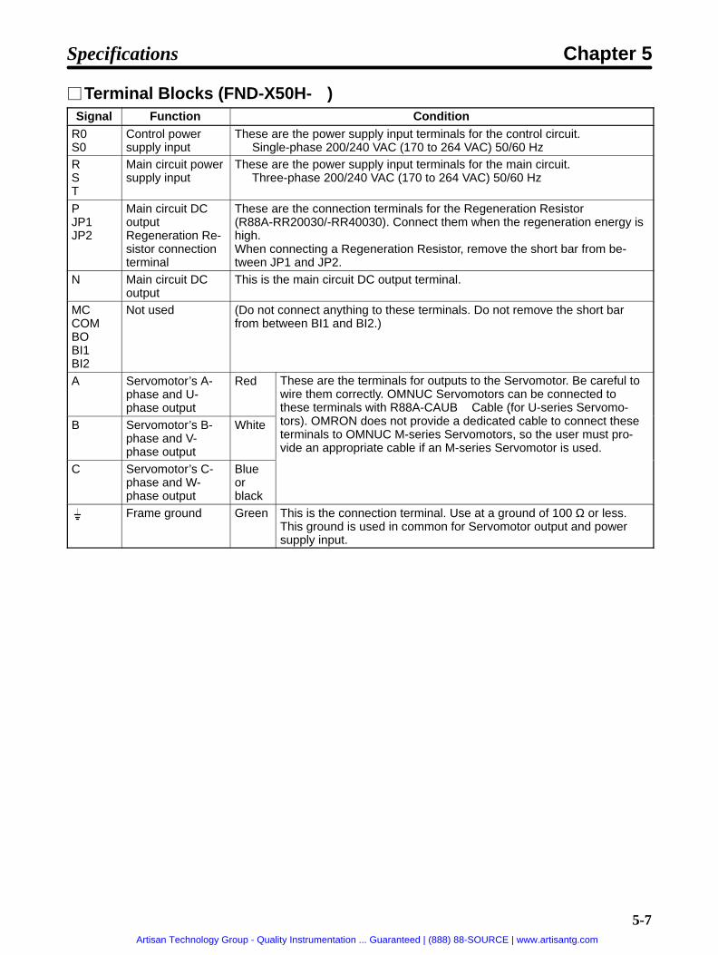
5-7
Terminal Blocks (FND-X50H- )Signal Function Condition
R0S0
Control powersupply input
These are the power supply input terminals for the control circuit.Single-phase 200/240 VAC (170 to 264 VAC) 50/60 Hz
RST
Main circuit powersupply input
These are the power supply input terminals for the main circuit.Three-phase 200/240 VAC (170 to 264 VAC) 50/60 Hz
PJP1JP2
Main circuit DCoutputRegeneration Re-sistor connectionterminal
These are the connection terminals for the Regeneration Resistor(R88A-RR20030/-RR40030). Connect them when the regeneration energy ishigh.When connecting a Regeneration Resistor, remove the short bar from be-tween JP1 and JP2.
N Main circuit DCoutput
This is the main circuit DC output terminal.
MCCOMBOBI1BI2
Not used (Do not connect anything to these terminals. Do not remove the short barfrom between BI1 and BI2.)
A Servomotor’s A-phase and U-phase output
Red These are the terminals for outputs to the Servomotor. Be careful towire them correctly. OMNUC Servomotors can be connected tothese terminals with R88A-CAUB Cable (for U-series Servomo-
) O OB Servomotor’s B-phase and V-phase output
White
(tors). OMRON does not provide a dedicated cable to connect theseterminals to OMNUC M-series Servomotors, so the user must pro-vide an appropriate cable if an M-series Servomotor is used.
C Servomotor’s C-phase and W-phase output
Blueorblack
Frame ground Green This is the connection terminal. Use at a ground of 100 Ω or less.This ground is used in common for Servomotor output and powersupply input.
Specifications Chapter 5
Artisan Technology Group - Quality Instrumentation ... Guaranteed | (888) 88-SOURCE | www.artisantg.com

5-8
CN2 (M.SEN) Motor Sensor Connectors (DIO, CompoBus/S)Pin No. Signal name Name I/O interface
1 E0V Encoder power supply ground Power supply output for encoder: 5 V,120 mA
2 S1 SIN excitation winding Resolver excitation signal output
3 S3 SIN excitation winding Resolver excitation signal output
4 E5V Encoder power supply, +5 V Power supply outlet for encoder: 5 V, 120 mA
5 NC --- ---
6 S2 COS excitation winding Resolver excitation signal output
7 S4 COS excitation winding Resolver excitation signal output8 +ABS Absolute encoder signal +
inputLine driver input (conforming to EIA-RS422A)(Input impedance: 220 Ω)
R1 Resolver signal input Resolver detection signal input9 –ABS Absolute encoder signal –
inputLine driver input (conforming to EIA-RS422A)(Input impedance: 220 Ω)
R2 Resolver signal input Resolver detection signal input10 NC --- ---
11 SG Resolver cable shield ground Resolver cable shield ground
12 +BAT Battery + Absolute encoder backup power supplyoutput:
13 –BAT Battery –out ut:3.6 V, 16 µA (for backup, rotation stopped)2µA (when +5-V voltage is applied)
14 S+/Z+ Encoder + S/+ Z-phase input Line driver input (conforming to EIA-RS422A)(Input impedance: 220 Ω)
15 S–/Z– Encoder – S/– Z-phase input Line driver input (conforming to EIA-RS422A)(Input impedance: 220 Ω)
16 A+ Encoder + A-phase input Line driver input (conforming to EIA-RS422A)(Input impedance: 220 Ω)
17 A– Encoder – A-phase input Line driver input (conforming to EIA-RS422A)(Input impedance: 220 Ω)
18 B+ Encoder + B-phase input Line driver input (conforming to EIA-RS422A)(Input impedance: 220 Ω)
19 B– Encoder – B-phase input Line driver input (conforming to EIA-RS422A)(Input impedance: 220 Ω)
20 FG Encoder cable shield ground Encoder cable shield ground
Connectors UsedReceptacle at Position Driver 10220-52A2JL (Sumitomo 3M)Soldered plug at cable side 10120-3000VE (Sumitomo 3M)Case at cable side 10320-52A0-008 (Sumitomo 3M)
Specifications Chapter 5
Artisan Technology Group - Quality Instrumentation ... Guaranteed | (888) 88-SOURCE | www.artisantg.com

5-9
CN2 (Motor Sensor Connector) Pin Arrangement
2 S1
4 E5V
8
10 NC
1 E0V
3 S3
7 S4
9
12
14 S+/Z+
16 A+
11 SG
13
17 A–
15 S–/Z–
6 S2
5 NC
18 B+
20 FG
19 B–
SIN excitationwinding
Encoderpowersupply, +5V
Encoderpower supplyground
Encoder+S/+Z-phaseinput
Encoder+A-phaseinput
Encodercable shieldground
+ABS
–ABS
+BAT
–BAT
Absolute en-coder signal +
Battery +
Resolvercable shieldground
R1 Resolversignal input
R2
SIN excitationwinding
COSexcitationwinding
Absolute en-coder signal –Resolversignal input
Encoder–S/–Z-phaseinput
Encoder+B-phaseinput Encoder –
B-phaseinput
Encoder –A-phaseinput
Battery –
COSexcitationwinding
CN5 (RS-232C) Communications Connectors (DIO, CompoBus/S)Pin No. Signal Name Interface
1 TXD Transmission data Transmission data (conforming to EIARS-232C)
2 DTR Transmission/reception-capableoutput
Transmission/reception-capableoutput (conforming to EIA RS-232C)
3 NC --- ---
4 RTS Reception-capable output Reception-capable output (conformingto EIA RS-232C)
5 RXD+ Reception data + Reception data (conforming to EIARS 422)
6 RXD– Reception data –RS-422)Input impedance: 330 Ω
7 TXD+ Transmission data + Transmission data (conforming to EIARS )8 TXD– Transmission data –
( gRS-422)
9 RXD Reception data Reception data (conforming to EIARS-232C)
10 CTS Reception-capable input Reception-capable input (conformingto EIA RS-232C)
11 +5V +5-V output External terminal power supply, 5 V,300 mA
12 FG Shield ground Shield ground
13 FG
g g
14 GND 0 V Power supply ground for externalterminal
Connectors UsedReceptacle at Position Driver 10214-52A2JL (Sumitomo 3M)Soldered plug at cable side 10114-3000VE (Sumitomo 3M)Case at cable side 10314-52A0-008 (Sumitomo 3M)
Specifications Chapter 5
Artisan Technology Group - Quality Instrumentation ... Guaranteed | (888) 88-SOURCE | www.artisantg.com

5-10
CN5 (Communications Connector) Pin Arrangement
2 DTR
4 RTS
1 TXD
3 NC
7 TXD+
9
11 +5V
13 FG
8 TXD–
10
14 GND
12 FG
6 RXD–
5 RXD+
Transmission/reception-ca-pable output
Reception-capableoutput
Receptiondata –
Transmissiondata
+5 output
Shieldground
0 V
RXD
CTS
Receptiondata +
Transmissiondata +
Receptiondata
Transmissiondata –
Reception-capable in-put
Shieldground
Monitor Output Terminal (MON)Pin No. Signal name Name I/O interface
1 GND Output ground Monitor ground
2 MON Monitor output Speed monitor: 3 V/motor’s rated speed, 1 mACurrent monitor: 3 V/motor’s maximum current, 1 mA
Connectors UsedConnectors at Position Driver B2B-EH-A (J.S.T. Mfg. Co., Ltd.)Cable housing EHR-2 (J.S.T. Mfg. Co., Ltd.)Cable contacts BEH-001T-P0.6 (J.S.T. Mfg. Co., Ltd.)
CN6 BAT ConnectorsPin No. Signal name Name I/O interface
1 FG Shield ground Shield ground
2 BAT Backup battery + input Absolute encoder backup batteryi i l V3 BATGND Backup battery – input
yconnection terminal, 2.8 to 4.5 V
Connectors UsedConnectors at Position Driver B3PS-VH (J.S.T. Mfg. Co., Ltd.)Cable housing VHR-3N (J.S.T. Mfg. Co., Ltd.)Cable contacts BVH-21T-P1.1 (J.S.T. Mfg. Co., Ltd.)
Specifications Chapter 5
Artisan Technology Group - Quality Instrumentation ... Guaranteed | (888) 88-SOURCE | www.artisantg.com

5-11
CN1 (CONT) Control Signal Connectors (DIO Position Drivers Only)
Control Inputs
Pin No. Symbol Name1 CCWL CCW limit input
2 CWL CW limit input
3 ORG Origin proximity
4 RUN RUN command
5 START START
6 RESET Alarm reset
7 SEARCH Origin search
8 +JOG +JOG operation
9 –JOG –JOG operation
10 TEACH TEACH
11 P.IN0 Point selection 0 / Position 0
12 P.IN1 Point selection 1 / Position 1
13 P.IN2 Point selection 2 / Position 2
14 P.IN3 Point selection 3 / Position 3
15 P.IN4 Point selection 4 / Position 4
16 P.IN5 Point selection 5 / Position 5
17 P.IN6 Point selection 6 / Position 6
18 P.IN7 Position 7
20 STOP Deceleration stop
36 +24V +24-V power supply input for control
Control Outputs
Pin No. Symbol Name19 OGND Output ground
21 BO Brake output
22 READY Ready
23 S.COM Origin search completed
24 ORGSTP Origin stop
25 T.COM Teaching completed
26 RUNON Motor running
27 INP Positioning completed
28 ALM Alarm
29 P.OUT0 Point output 0 / Position selection 1
30 P.OUT1 Point output 1 / Position selection 2
31 P.OUT2 Point output 2 / Position selection 3
32 P.OUT3 Point output 3 / Position selection 4
33 P.OUT4 Point output 4 / Speed selection
34 P.OUT5 Point output 5
35 P.OUT6 Point output 6
Specifications Chapter 5
Artisan Technology Group - Quality Instrumentation ... Guaranteed | (888) 88-SOURCE | www.artisantg.com

5-12
Connectors UsedReceptacle at Position Driver 10236-6202JL (Sumitomo 3M)Soldered plug at cable side 10136-3000VE (Sumitomo 3M)Case at cable side 10336-52A0-008 (Sumitomo 3M)
Note 1. The control input interface is a photocoupler input of 24 VDC at 8 mA.
Note 2. For the external power supply, use 24 VDC ±1 V at 150 mA minimum.
Note 3. The control output interface is a photocoupler output of 24 VDC at 40 mA.
CN1 (Control Signal Connector) Pin Arrangement
2 CWL
4 RUN
8
10 TEACH
1 CCWL
3 ORG
7 SEARCH
9
20
22 READY
24 ORGSTP
19 OGND
21
25 T.COM
23 S.COM
6 RESET
5 START
26 RUNON
28 ALM
27 INP
CW limit in-put
RUNcommand
Alarm reset
Originproximity
START
Origin search
READY
Originstop
Motorrunning
Alarm
Originsearchcompleted
Teachingcompleted
Positioningcompleted
+JOG
–JOG
STOP
BO
+JOG op-eration
Decelerationstop
Brakeoutput
12 P.IN1
14 P.IN3
18
16 P.IN5
Pointselection 1/Position 1
P.IN7 Position 7
11 P.IN0
13 P.IN2
17 P.IN6
15 P.IN4
Teach
30
32 P.OUT3
34 P.OUT5
36 +24V
Pointoutput 5
+24-V powersupply inputfor control
P.OUT1
Outputground
29 P.OUT0
31
35 P.OUT6
33 P.OUT4
P.OUT2
Point output0/ Positionselection 1
Pointselection 3/Position 3
Pointselection 5/Position 5
CCW limitinput
–JOG op-eration
Pointselection 0/Position 0
Pointselection 2/Position 2
Pointselection 4/Position 4
Pointselection 6/Position 6
Pointoutput 1/Positionselection 2Pointoutput 3/Positionselection 4
Point output2/ Positionselection 3
Point output4/ Speedselection
Point output 6
Specifications Chapter 5
Artisan Technology Group - Quality Instrumentation ... Guaranteed | (888) 88-SOURCE | www.artisantg.com

5-13
CN1 (CONT) CompoBus/S Communications TerminalsSymbol Name Function
BD H CompoBus/S serial line (+) These are the terminals for connecting CompoBus/Scommunications cable When wiring them be careful with the
BD L CompoBus/S serial line (–)communications cable. When wiring them, be careful with thepolarity.
IN (16 Input Points)I/O allocation Symbol NameOUT0 RUN RUN command
OUT1 START Start
OUT2 RESET Alarm reset
OUT3 SEARCH Origin search
OUT4 +JOG +JOG operation
OUT5 –JOG –JOG operation
OUT6 TEACH Teach
OUT7 STOP Deceleration stop
OUT8 P.IN0 Point selection 0 / Position 0
OUT9 P.IN1 Point selection 1 / Position 1
OUT10 P.IN2 Point selection 2 / Position 2
OUT11 P.IN3 Point selection 3 / Position 3
OUT12 P.IN4 Point selection 4 / Position 4
OUT13 P.IN5 Point selection 5 / Position 5
OUT14 P.IN6 Point selection 6 / Position 6
OUT15 P.IN7 Position 7
OUT (16 Output Points)I/O allocation Symbol NameIN0 BO Brake output
IN1 READY Ready
IN2 S.COM Origin search completed
IN3 ORGSTP Origin stop
IN4 T.COM Teaching completed
IN5 RUNON Motor running
IN6 INP Positioning completed
IN7 ALM Alarm
IN8 P.OUT0 Point output 0 / Position selection 1
IN9 P.OUT1 Point output 1 / Position selection 2
IN10 P.OUT2 Point output 2 / Position selection 3
IN11 P.OUT3 Point output 3 / Position selection 4
IN12 P.OUT4 Point output 4 / Speed selection
IN13 P.OUT5 Point output 5
IN14 P.OUT6 Point output 6
IN15 --- Not used
Note For I/O allocation, refer to the operation manual for the Master Unit.
Specifications Chapter 5
Artisan Technology Group - Quality Instrumentation ... Guaranteed | (888) 88-SOURCE | www.artisantg.com

5-14
CN4 (LIMIT) External Control Signal Connectors (CompoBus/S Only)Pin No. Symbol Name
1 CCWL CCW limit input
2 CWL CW limit input
3 ORG Origin proximity
4 STOP Deceleration stop
5 NC
6 NC
7 +24V +24-V power supply input for control
8 BO Brake output
9 NC
10 NC
11 NC
12 NC
13 NC
14 0GND Ground
Connectors UsedReceptacle at Position Driver 10214-6202JL (Sumitomo 3M)Soldered plug at cable side 10114-3000VE (Sumitomo 3M)Case at cable side 10314-52A0-008 (Sumitomo 3M)
Note 1. The control input interface is a photocoupler input of 24 VDC at 8 mA.
Note 2. For the external power supply, use 24 VDC ±1 V at 40 mA minimum.
Note 3. The control output interface is a photocoupler output of 24 VDC at 40 mA.
CN4 Pin Arrangement
2 CWL
4 STOP
1 CCWL
3 ORG
7
9
11
13
8 BO
10
14 OGND
12
6
5
CW limit in-put
Decelerationstop
Originproximity
+24V+24-V powersupply inputfor control
Brakeoutput
CCW limitinput
Outputground
Specifications Chapter 5
Artisan Technology Group - Quality Instrumentation ... Guaranteed | (888) 88-SOURCE | www.artisantg.com
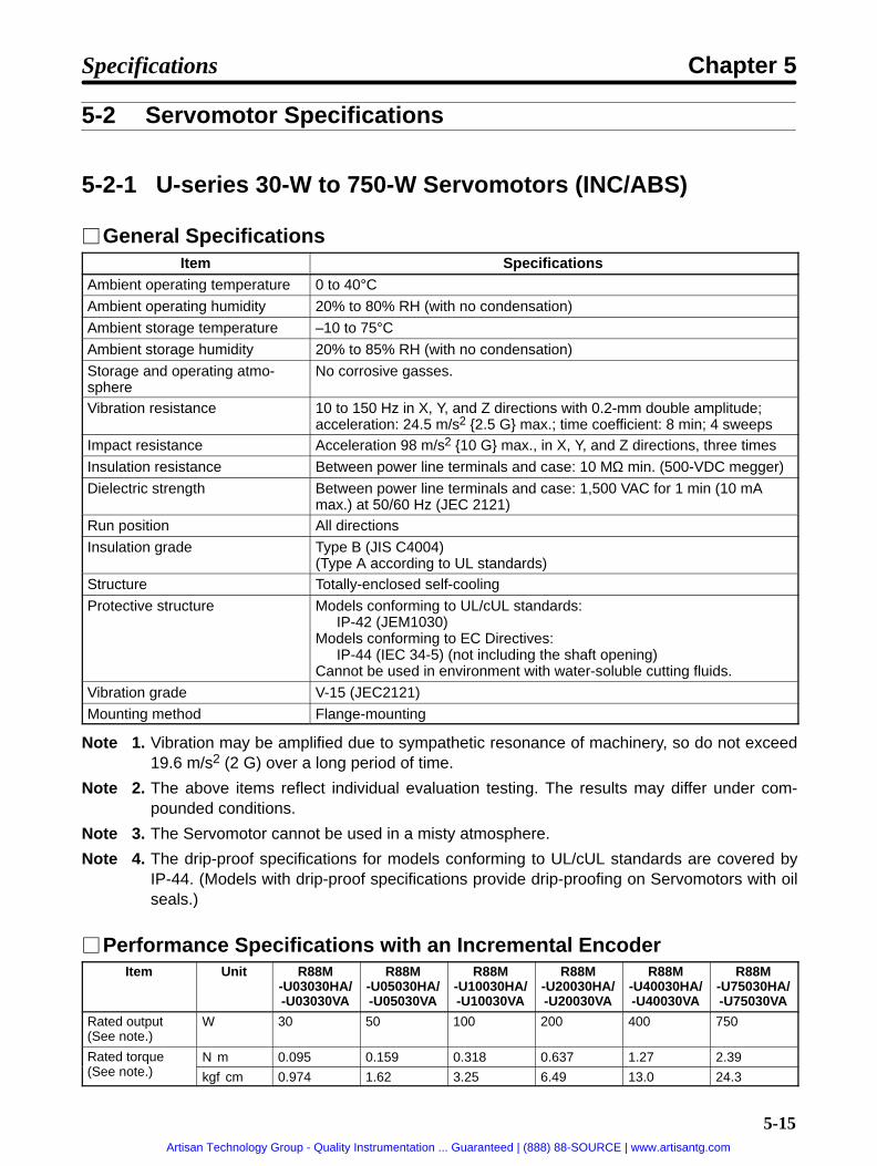
5-15
5-2 Servomotor Specifications
5-2-1 U-series 30-W to 750-W Servomotors (INC/ABS)
General SpecificationsItem Specifications
Ambient operating temperature 0 to 40°CAmbient operating humidity 20% to 80% RH (with no condensation)
Ambient storage temperature –10 to 75°CAmbient storage humidity 20% to 85% RH (with no condensation)
Storage and operating atmo-sphere
No corrosive gasses.
Vibration resistance 10 to 150 Hz in X, Y, and Z directions with 0.2-mm double amplitude;acceleration: 24.5 m/s2 2.5 G max.; time coefficient: 8 min; 4 sweeps
Impact resistance Acceleration 98 m/s2 10 G max., in X, Y, and Z directions, three times
Insulation resistance Between power line terminals and case: 10 MΩ min. (500-VDC megger)
Dielectric strength Between power line terminals and case: 1,500 VAC for 1 min (10 mAmax.) at 50/60 Hz (JEC 2121)
Run position All directions
Insulation grade Type B (JIS C4004)(Type A according to UL standards)
Structure Totally-enclosed self-cooling
Protective structure Models conforming to UL/cUL standards:IP-42 (JEM1030)
Models conforming to EC Directives:IP-44 (IEC 34-5) (not including the shaft opening)
Cannot be used in environment with water-soluble cutting fluids.
Vibration grade V-15 (JEC2121)
Mounting method Flange-mounting
Note 1. Vibration may be amplified due to sympathetic resonance of machinery, so do not exceed19.6 m/s2 (2 G) over a long period of time.
Note 2. The above items reflect individual evaluation testing. The results may differ under com-pounded conditions.
Note 3. The Servomotor cannot be used in a misty atmosphere.
Note 4. The drip-proof specifications for models conforming to UL/cUL standards are covered byIP-44. (Models with drip-proof specifications provide drip-proofing on Servomotors with oilseals.)
Performance Specifications with an Incremental EncoderItem Unit R88M
-U03030HA/-U03030VA
R88M-U05030HA/-U05030VA
R88M-U10030HA/-U10030VA
R88M-U20030HA/-U20030VA
R88M-U40030HA/-U40030VA
R88M-U75030HA/-U75030VA
Rated output(See note.)
W 30 50 100 200 400 750
Rated torque(S )
Nm 0.095 0.159 0.318 0.637 1.27 2.39q(See note.) kgfcm 0.974 1.62 3.25 6.49 13.0 24.3
Specifications Chapter 5
Artisan Technology Group - Quality Instrumentation ... Guaranteed | (888) 88-SOURCE | www.artisantg.com
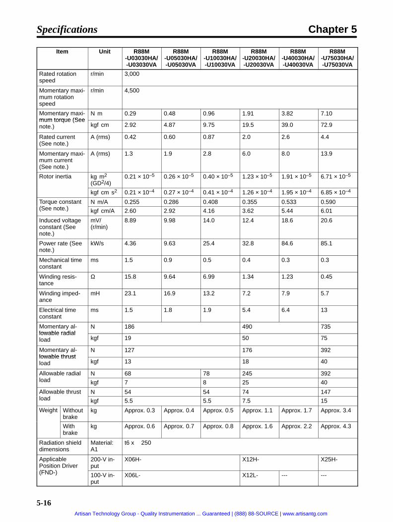
5-16
Item R88M-U75030HA/-U75030VA
R88M-U40030HA/-U40030VA
R88M-U20030HA/-U20030VA
R88M-U10030HA/-U10030VA
R88M-U05030HA/-U05030VA
R88M-U03030HA/-U03030VA
Unit
Rated rotationspeed
r/min 3,000
Momentary maxi-mum rotationspeed
r/min 4,500
Momentary maxi-mum torque (See
Nm 0.29 0.48 0.96 1.91 3.82 7.10mum torque (Seenote.) kgfcm 2.92 4.87 9.75 19.5 39.0 72.9
Rated current(See note.)
A (rms) 0.42 0.60 0.87 2.0 2.6 4.4
Momentary maxi-mum current(See note.)
A (rms) 1.3 1.9 2.8 6.0 8.0 13.9
Rotor inertia kgm2
(GD2/4)0.21 × 10–5 0.26 × 10⁻⁵ 0.40 × 10⁻⁵ 1.23 × 10⁻⁵ 1.91 × 10⁻⁵ 6.71 × 10⁻⁵
kgfcms2 0.21 × 10⁻⁴ 0.27 × 10⁻⁴ 0.41 × 10⁻⁴ 1.26 × 10⁻⁴ 1.95 × 10⁻⁴ 6.85 × 10⁻⁴
Torque constant(S )
Nm/A 0.255 0.286 0.408 0.355 0.533 0.590q(See note.) kgfcm/A 2.60 2.92 4.16 3.62 5.44 6.01
Induced voltageconstant (Seenote.)
mV/(r/min)
8.89 9.98 14.0 12.4 18.6 20.6
Power rate (Seenote.)
kW/s 4.36 9.63 25.4 32.8 84.6 85.1
Mechanical timeconstant
ms 1.5 0.9 0.5 0.4 0.3 0.3
Winding resis-tance
Ω 15.8 9.64 6.99 1.34 1.23 0.45
Winding imped-ance
mH 23.1 16.9 13.2 7.2 7.9 5.7
Electrical timeconstant
ms 1.5 1.8 1.9 5.4 6.4 13
Momentary al-lowable radial
N 186 490 735lowable radialload kgf 19 50 75
Momentary al-lowable thrust
N 127 176 392lowable thrustload kgf 13 18 40
Allowable radiall d
N 68 78 245 392load kgf 7 8 25 40
Allowable thrustl d
N 54 54 74 147load kgf 5.5 5.5 7.5 15
Weight Withoutbrake
kg Approx. 0.3 Approx. 0.4 Approx. 0.5 Approx. 1.1 Approx. 1.7 Approx. 3.4
Withbrake
kg Approx. 0.6 Approx. 0.7 Approx. 0.8 Approx. 1.6 Approx. 2.2 Approx. 4.3
Radiation shielddimensions
Material:A1
t6 x 250
ApplicablePosition Driver(FND )
200-V in-put
X06H- X12H- X25H-
(FND-) 100-V in-put
X06L- X12L- --- ---
Specifications Chapter 5
Artisan Technology Group - Quality Instrumentation ... Guaranteed | (888) 88-SOURCE | www.artisantg.com

5-17
Item R88M-U75030HA/-U75030VA
R88M-U40030HA/-U40030VA
R88M-U20030HA/-U20030VA
R88M-U10030HA/-U10030VA
R88M-U05030HA/-U05030VA
R88M-U03030HA/-U03030VA
Unit
Brakespeci-fi
Brakeinertia
kgm2
(GD2/4)0.09 x 10–5 0.58 x 10⁻⁵ 1.40 x 10⁻⁵
fica-tions
kgfcms2 0.09 x 10⁻⁴ 0.59 x 10⁻⁴ 1.43 x 10⁻⁴tions
Excita-tionvoltage
V 24 VDC ±10% (No polarity)
Powercon-sumption
W (at20°C)
6.0 6.5 6.0
Currentcon-sump-tion
A (at20°C)
0.25 0.27 0.25
Staticfriction
Nm 0.2 min. 0.34 min. 1.5 min. 2.5 min.frictiontorque kgfcm 2.0 min. 3.5 min. 15.0 min. 25.0 min.
Absorp-tiontime(Seenote 3.)
ms 40 max. 60 max. 100 max. 200 max.
Releasetime(Seenote 3.)
ms 20 max. 30 max. 40 max. 50 max.
Back-lash
(Referencevalue)
±1°
Rating --- Continuous
Insula-tiongrade
--- Type F
Note 1. The values for torque and rotation speed characteristics, are the values at an armature wind-ing temperature of 100°C, combined with the Position Driver. Other values are at normalconditions (20°C, 65%). The maximum momentary torque is a reference value.
Note 2. The brakes are the non-excitation type. (When excitation voltage is added, it is cleared.)
Note 3. The operation time measurement is the measured value with a surge killer (CR50500, byOkaya Electric Industrial Co.) installed.
Note 4. The allowable radial load indicates the value at a location 5 mm from the end of the shaft. (Seethe diagram below.)
Radial loadThrust load
5 mm
Note 5. The allowable radial load and the allowable thrust load are the values determined by taking aservice life of 20,000 hours at normal usage as the standard.
Specifications Chapter 5
Artisan Technology Group - Quality Instrumentation ... Guaranteed | (888) 88-SOURCE | www.artisantg.com

5-18
Performance Specifications with an Absolute Encoder
Item Unit R88M-U03030TA/-U03030XA
R88M-U05030TA/-05030XA
R88M-U10030TA/-U10030XA
R88M-U20030TA/-U20030XA
R88M-U40030TA/-U40030XA
R88M-U75030TA/-U75030XA
Rated output(See note.)
W 30 50 100 200 400 750
Rated torque(S )
Nm 0.095 0.159 0.318 0.637 1.27 2.39q(See note.) kgfcm 0.974 1.62 3.25 6.49 13.0 24.3
Rated rotationspeed
r/min 3,000
Momentary maxi-mum rotationspeed
r/min 4,500
Momentary maxi-mum torque (See
Nm 0.29 0.48 0.96 1.91 3.82 7.10mum torque (Seenote.) kgfcm 2.92 4.87 9.75 19.5 39.0 72.9
Rated current(See note.)
A (rms) 0.42 0.60 0.87 2.0 2.6 4.4
Momentary maxi-mum current(See note.)
A (rms) 1.3 1.9 2.8 6.0 8.0 13.9
Rotor inertia kgm2
(GD2/4)0.46 × 10–5 0.51 × 10⁻⁵ 0.65 × 10⁻⁵ 1.48 × 10⁻⁵ 2.16 × 10⁻⁵ 6.96 × 10⁻⁵
kgfcms2 0.47 × 10⁻⁴ 0.53 × 10⁻⁴ 0.67 × 10⁻⁴ 1.52 × 10⁻⁴ 2.21 × 10⁻⁴ 7.11 × 10⁻⁴
Torque constant(S )
Nm/A 0.255 0.286 0.408 0.355 0.533 0.590q(See note.) kgfcm/A 2.60 2.92 4.16 3.62 5.44 6.01
Induced voltageconstant (Seenote.)
mV/(r/min)
8.89 9.98 14.0 12.4 18.6 20.6
Power rate (Seenote.)
kW/s 4.36 9.63 25.4 32.8 84.6 85.1
Mechanical timeconstant
ms 1.5 0.9 0.5 0.4 0.3 0.3
Winding resis-tance
Ω 15.8 9.64 6.99 1.34 1.23 0.45
Winding imped-ance
mH 23.1 16.9 13.2 7.2 7.9 5.7
Electrical timeconstant
ms 1.5 1.8 1.9 5.4 6.4 13
Momentary al-lowable radial
N 186 490 735lowable radialload kgf 19 50 75
Momentary al-lowable thrust
N 127 176 392lowable thrustload kgf 13 18 40
Allowable radiall d
N 68 78 245 392load kgf 7 8 25 40
Allowable thrustl d
N 54 49 68 147load kgf 5.5 5 7 15
Weight Withoutbrake
kg Approx.0.45
Approx.0.55
Approx.0.65
Approx. 1.2 Approx. 1.8 Approx. 3.5
Withbrake
kg Approx.0.75
Approx.0.85
Approx.0.95
Approx. 1.7 Approx. 2.3 Approx. 4.5
Specifications Chapter 5
Artisan Technology Group - Quality Instrumentation ... Guaranteed | (888) 88-SOURCE | www.artisantg.com

5-19
Item R88M-U75030TA/-U75030XA
R88M-U40030TA/-U40030XA
R88M-U20030TA/-U20030XA
R88M-U10030TA/-U10030XA
R88M-U05030TA/-05030XA
R88M-U03030TA/-U03030XA
Unit
Radiation shielddimensions
Material:A1
t6 x 250
ApplicablePosition Driver(FND )
200-Vinput
X06H- X12H- X25H-
(FND-) 100-Vinput
X06L- X12L- --- ---
Brakespeci-fi
Brakeinertia
kgm2
(GD2/4)0.09 x 10–5 0.58 x 10⁻⁵ 1.40 x 10⁻⁵
fica-tions
kgfcms2 0.09 x 10⁻⁴ 0.59 x 10⁻⁴ 1.43 x 10⁻⁴tions
Excita-tionvoltage
V 24 VDC ±10% (No polarity)
Powercon-sump-tion
W (at20°C)
6.0 6.5 6.0
Currentcon-sump-tion
A (at20°C)
0.25 0.27 0.25
Staticfriction
Nm 0.2 min. 0.34 min. 1.5 min. 2.5 min.frictiontorque kgfcm 2.0 min. 3.5 min. 15.0 min. 25.0 min.
Absorp-tiontime(Seenote 3.)
ms 40 max. 60 max. 100 max. 200 max.
Releasetime(Seenote 3.)
ms 20 max. 30 max. 40 max. 50 max.
Back-lash
(Referencevalue)
±1°
Rating --- Continuous
Insula-tiongrade
--- Type F
Note 1. The values for torque and rotation speed characteristics, are the values at an armature wind-ing temperature of 100°C, combined with the Position Driver. Other values are at normalconditions (20°C, 65%). The maximum momentary torque is a reference value.
Note 2. The brakes are the non-excitation type. (When excitation voltage is added, it is cleared.)
Note 3. The operation time measurement is the measured value with a surge killer (CR50500, byOkaya Electric Industrial Co.) installed.
Specifications Chapter 5
Artisan Technology Group - Quality Instrumentation ... Guaranteed | (888) 88-SOURCE | www.artisantg.com

5-20
Note 4. The allowable radial load indicates the value at a location 5 mm from the end of the shaft. (Seethe diagram below.)
Radial load
Thrust load
5 mm
Note 5. The allowable radial load and the allowable thrust load are the values determined by taking aservice life of 20,000 hours at normal usage as the standard.
Torque and Rotation Speed Characteristics (Standard Cable: 3 m; 200/100-VAC Input)
Repeatedused area
Continuous op-eration area
R88M-U03030HA/TAR88M-U03030VA/XA
R88M-U05030HA/TAR88M-U05030VA/XA
R88M-U10030HA/TAR88M-U10030VA/XA
R88M-U20030HA/TAR88M-U20030VA/XA
R88M-U40030HA/TAR88M-U40030VA/XA
R88M-U75030HA/TAR88M-U75030VA/XA
Repeatedused area
Repeatedused area
Repeatedused area Repeated
used areaRepeatedused area
Continuous op-eration area
Continuous op-eration area
Continuous op-eration area
Continuous op-eration area
Continuous op-eration area
Servomotor and Mechanical System Temperature Characteristics• U-series AC Servomotors use rare earth magnets (neodymium–iron magnets). The temperature co-
efficient for these magnets is approximately -0.13%/°C. As the temperature drops, the Servomotor’smomentary maximum torque increases, and as the temperature rises the Servomotor’s momentarymaximum torque decreases. When the normal temperature of 20°C and -10°C are compared, themomentary maximum torque increases by approximately 4%. Conversely, when the magnet warmsup to 80°C from the normal temperature of 20°C, the momentary maximum torque decreases byapproximately 8%.
Specifications Chapter 5
Artisan Technology Group - Quality Instrumentation ... Guaranteed | (888) 88-SOURCE | www.artisantg.com

5-21
• Generally, in a mechanical system, when the temperature drops the friction torque increases and theload torque becomes larger. For that reason, overloading may occur at low temperatures. In particu-lar, in systems which use deceleration devices, the load torque at low temperatures may be nearlytwice the load torque at normal temperatures. Check with a current monitor to see whether overload-ing is occurring at low temperatures, and how much the load torque is. Likewise, check to see wheth-er there abnormal Servomotor overheating or alarms are occurring at high temperatures.
• An increase in load friction torque visibly increases load inertia. Therefore, even if the Position Driverparameters are adjusted at a normal temperature, there may not be optimal operation at low temper-atures. Check to see whether there is optimal operation at low temperatures too.
Incremental Encoder SpecificationsItem Standards
Encoder method Optical incremental encoder
Number of output pulses A, B phase: 2,048 pulses/revolution, Z phase: 1 pulse/revolution
Power supply voltage 5 VDC±5%
Power supply current DC, 350 mA (for load resistance of 220 Ω)
Pulse duty characteristics 50% ±10%
Phase characteristics 90° ±43.2°Phase relationship For rotation in the CW direction, A phase is advanced by 90° compared
to B phase.Maximum rotation speed 4,500 r/min
Maximum response frequency 153.6 kHz
Output signals +A, –A, +B, –B, +S, –S
Output interface Conforming to EIA RS-422A. Output based on AM26LS31CN or equivalent.
Serial communications data Z phase, poll sensor, U, V, W phase
Serial communications method Combination communications method based on A, B, and S phases.
Specifications Chapter 5
Artisan Technology Group - Quality Instrumentation ... Guaranteed | (888) 88-SOURCE | www.artisantg.com

5-22
Absolute Encoder SpecificationsItem Standards
Encoder method Optical absolute encoder
Number of output pulses A, B phase: 1,024 pulses/revolution, Z phase: 1 pulse/revolution
Maximum rotational amount ±99,999 revolution
Power supply voltage 5 VDC±5%
Power supply current DC, 170 mA (for load resistance of 220 Ω)
Applicable battery voltage 3.6 VDC
Battery consumption current 16 µA during backup or when operation is stopped, 2 µA when 5 V issupplied
Pulse duty characteristics 50% ±10%
Phase characteristics 90° ±36°Phase relationship For rotation in the CW direction, A phase is advanced by 90° compared
to B phase.Maximum rotation speed 4,500 r/min
Maximum response frequency 76.8 kHz
Output signals +A, –A, +B, –B, +Z, –Z, +ABS, –ABS
Output interface Conforming to EIA RS-422A.Output based on MC3487 or equivalent.
Absolute-value communicationsdata
Rotation amountAbsolute position within rotation
5-2-2 U-UE-series Servomotors
General SpecificationsItem Specifications
Ambient operating temperature 0°C to 40°CAmbient operating humidity 20% to 80% RH (with no condensation)
Ambient storage temperature –10°C to 75°CAmbient storage humidity 20% to 85% RH (with no condensation)
Storage and operating atmo-sphere
No corrosive gasses.
Vibration resistance 10 to 150 Hz in X, Y, and Z directions with 0.2-mm double amplitude;acceleration: 24.5 m/s2 2.5 G max.; time coefficient: 8 min; 4 sweeps
Impact resistance Acceleration 98 m/s2 10 G max., in X, Y, and Z directions, three times
Insulation resistance Between power line terminals and case: 10 MΩ min. (500-VDC megger)
Dielectric strength Between power line terminals and case: 1,500 VAC for 1 min (10 mAmax.) at 50/60 Hz (JEC 2121)
Run position All directions
Insulation grade Type B (JIS C4004)
Structure Totally-enclosed self-cooling
Protective structure Models not conforming to any standards:IP-42 (JEM1030)
Models conforming to EC Directives:IP-44 (IEC 34-5) (not including the shaft opening)
Cannot be used in environment with water-soluble cutting fluids.
Vibration grade V-15 (JEC2121)
Mounting method Flange-mounting
Specifications Chapter 5
Artisan Technology Group - Quality Instrumentation ... Guaranteed | (888) 88-SOURCE | www.artisantg.com

5-23
Note 1. Vibration may be amplified due to sympathetic resonance of machinery, so do not exceed19.6 m/s2 (2 G) over a long period of time.
Note 2. The above items reflect individual evaluation testing. The results may differ under com-pounded conditions.
Note 3. The Servomotor cannot be used in a misty atmosphere.
Performance SpecificationsItem Unit R88M
-UE10030H-S1/-UE10030V-S1
R88M-UE20030H-S1/-UE20030V-S1
R88M-UE40030H-S1/-UE40030V-S1
R88M-UE75030H-S1/-UE75030V-S1
Rated output(See note.)
W 100 200 400 750
Rated torque(S )
Nm 0.318 0.637 1.27 2.39q(See note.) kgfcm 3.25 6.49 13.0 24.3
Rated rotation speed r/min 3,000
Momentary maximumrotation speed
r/min 4,500
Momentary maximum(S )
Nm 0.96 1.91 3.82 7.10ytorque (See note.) kgfcm 9.75 19.5 39.0 72.9
Rated current(See note.)
A (rms) 0.87 2.0 2.6 4.4
Momentary maximumcurrent (See note.)
A (rms) 2.8 6.0 8.0 13.9
Rotor inertia kgm2 (GD2/4) 0.40 × 10⁻⁵ 1.23 × 10⁻⁵ 1.91 × 10⁻⁵ 6.71 × 10⁻⁵
kgfcms2 0.41 × 10⁻⁴ 1.26 × 10⁻⁴ 1.95 × 10⁻⁴ 6.85 × 10⁻⁴
Torque constant(S )
Nm/A 0.408 0.355 0.533 0.590q(See note.) kgfcm/A 4.16 3.62 5.44 6.01
Induced voltageconstant (See note.)
mV/ (r/min) 14.0 12.4 18.6 20.6
Power rate (See note.) kW/s 25.4 32.8 84.6 85.1
Mechanical timeconstant
ms 0.5 0.4 0.3 0.3
Winding resistance Ω 6.99 1.34 1.23 0.45
Winding impedance mH 13.2 7.2 7.9 5.7
Electrical time constant ms 1.9 5.4 6.4 13
Momentary allowabledi l l d
N 186 490 735yradial load kgf 19 50 75
Momentary allowableh l d
N 127 176 392ythrust load kgf 13 18 40
Allowable radial load N 78 245 392
kgf 8 25 40
Allowable thrust load N 54 74 147
kgf 5.5 7.5 15
Weight Withoutbrake
kg Approx. 0.5 Approx. 1.1 Approx. 1.7 Approx. 3.4
With brake kg Approx. 0.8 Approx. 1.6 Approx. 2.2 Approx. 4.3
Radiation shield dimen-sions
Material: A1 t6 x 250
ApplicableP i i D i (FND )
200-V input X06H- X12H- X25H-Position Driver (FND-) 100-V input X06L- X12L- --- ---
Specifications Chapter 5
Artisan Technology Group - Quality Instrumentation ... Guaranteed | (888) 88-SOURCE | www.artisantg.com

5-24
Item R88M-UE75030H-S1/-UE75030V-S1
R88M-UE40030H-S1/-UE40030V-S1
R88M-UE20030H-S1/-UE20030V-S1
R88M-UE10030H-S1/-UE10030V-S1
Unit
Brakeifi
Brake iner-i
kgm2 (GD2/4) 0.09 x 10⁻⁵ 0.58 x 10⁻⁵ 1.40 x 10⁻⁵
specifica-tions
tia kgfcms2 0.09 x 10⁻⁴ 0.59 x 10⁻⁴ 1.43 x 10⁻⁴tions
Excitationvoltage
V 24 VDC ±10% (No polarity)
Power con-sumption
W (at 20°C) 6.0 6.5 6.0
Currentconsump-tion
A (at 20°C) 0.25 0.27 0.25
Static fric-i
Nm 0.34 min. 1.5 min. 2.5 min.tion torque kgfcm 3.5 min. 15.0 min. 25.0 min.
Absorptiontime (Seenote 3.)
ms 60 max. 100 max. 200 max.
Releasetime (Seenote 3.)
ms 30 max. 40 max. 50 max.
Backlash (Reference val-ue)
±1°
Rating --- Continuous
Insulationgrade
--- Type F
Note 1. The values for torque and rotation speed characteristics, are the values at an armature wind-ing temperature of 100°C, combined with the Position Driver. Other values are at normalconditions (20°C, 65%). The maximum momentary torque is a reference value.
Note 2. The brakes are the non-excitation type. (When excitation voltage is added, it is cleared.)
Note 3. The operation time measurement is the measured value with a surge killer (CR50500, byOkaya Electric Industrial Co.) installed.
Note 4. The allowable radial load indicates the value at a location 5 mm from the end of the shaft. (Seethe diagram below.)
Radial load
Thrust load
5 mm
Note 5. The allowable radial load and the allowable thrust load are the values determined by taking aservice life of 20,000 hours at normal usage as the standard.
Note 6. U-series UE Servomotors can be used only with Position Driver software version 4.01 (Sep-tember 1997) or later.
Specifications Chapter 5
Artisan Technology Group - Quality Instrumentation ... Guaranteed | (888) 88-SOURCE | www.artisantg.com

5-25
Torque and Rotation Speed Characteristics (Standard Cable: 3 m; 200/100-VAC Input)
R88M-UE10030H-S1R88M-UE10030V-S1
R88M-UE20030H-S1R88M-UE20030V-S1
R88M-UE40030H-S1R88M-UE40030V-S1
R88M-UE75030H-S1R88M-UE75030V-S1
Repeated use area
Continuous opera-tion area
Repeated use area
Continuous opera-tion area
Repeated use area
Continuous opera-tion area
Repeated use area
Continuous opera-tion area
Servomotor and Mechanical System Temperature Characteristics• U-UE-series AC Servomotors use rare earth magnets (neodymium–iron magnets). The tempera-
ture coefficient for these magnets is approximately -0.13%/°C. As the temperature drops, the Servo-motor’s momentary maximum torque increases, and as the temperature rises the Servomotor’s mo-mentary maximum torque decreases. When the normal temperature of 20°C and -10°C arecompared, the momentary maximum torque increases by approximately 4%. Conversely, when themagnet warms up to 80°C from the normal temperature of 20°C, the momentary maximum torquedecreases by approximately 8%.
• Generally, in a mechanical system, when the temperature drops the friction torque increases and theload torque becomes larger. For that reason, overloading may occur at low temperatures. In particu-lar, in systems which use deceleration devices, the load torque at low temperatures may be nearlytwice the load torque at normal temperatures. Check with a current monitor to see whether overload-ing is occurring at low temperatures, and how much the load torque is. Likewise, check to see wheth-er there abnormal Servomotor overheating or alarms are occurring at high temperatures.
• An increase in load friction torque visibly increases load inertia. Therefore, even if the Position Driverparameters are adjusted at a normal temperature, there may not be optimal operation at low temper-atures. Check to see whether there is optimal operation at low temperatures too.
Specifications Chapter 5
Artisan Technology Group - Quality Instrumentation ... Guaranteed | (888) 88-SOURCE | www.artisantg.com

5-26
Encoder SpecificationsItem Standards
Encoder method Optical incremental encoder
Number of output pulses A, B phase: 1,024 pulses/revolution, Z phase: 1 pulse/revolution
Power supply voltage 5 VDC±5%
Power supply current DC, 350 mA (for load resistance of 220 Ω)
Pulse duty characteristics 50% ±10%
Phase characteristics 90° ±43.2°Phase relationship For rotation in the CW direction, A phase is advanced by 90° compared
to B phase.Maximum rotation speed 4,500 r/min
Maximum response frequency 76.8 kHz
Output signals +A, –A, +B, –B, +S, –S
Output interface Conforming to EIA RS-422A. Output based on AM26LS31CN or equivalent.
Serial communications data Z phase, poll sensor, U, V, W phase
Serial communications method Combination communications method based on A, B, and S phases.
5-2-3 U-series 1-kW to 2-kW Servomotors (INC/ABS)
General SpecificationsItem Specifications
Ambient operating temperature 0 to 40°CAmbient operating humidity 20% to 80% RH (with no condensation)
Ambient storage temperature –20 to 60°CAmbient storage humidity 20% to 80% RH (with no condensation)
Storage and operating atmo-sphere
No corrosive gasses.
Vibration resistance 10 to 150 Hz in X, Y, and Z directions with 0.2-mm double amplitude;acceleration: 24.5 m/s2 2.5 G max.; time coefficient: 8 min; 4 sweeps
Impact resistance Acceleration 98 m/s2 10 G max., in X, Y, and Z directions, three times
Insulation resistance Between power line terminals and case: 10 MΩ min. (500-VDC megger)
Dielectric strength Between power line terminals and case: 1,500 VAC for 1 min (10 mAmax.) at 50/60 Hz (JEC 2121)
Run position All directions
Insulation grade Type F (JIS C4004)
Structure Totally-enclosed self-cooling
Protective structure Models not conforming to any standards:IP-65 (IEC 34-5) (This standard does not apply to the shaft opening.
The connector used for the standard cable conforms to IP-30.)Models conforming to EC Directives:
IP-55 (IEC 34-5) (This standard does not apply to the shaft opening.The connector used for the standard cable conforms to IP-30.)Cannot be used in environment with water-soluble cutting fluids.
Vibration grade V-15 (JEC2121)
Mounting method Flange-mounting
Specifications Chapter 5
Artisan Technology Group - Quality Instrumentation ... Guaranteed | (888) 88-SOURCE | www.artisantg.com

5-27
Note 1. Vibration may be amplified due to sympathetic resonance of machinery, so do not exceed19.6 m/s2 (2 G) over a long period of time.
Note 2. Use water-resistance cables for the power cables and encoder cables in locations subject tocontact with water.
Note 3. The above items reflect individual evaluation testing. The results may differ under com-pounded conditions.
Note 4. The Servomotor cannot be used in a misty atmosphere.
Performance Specifications with an Incremental EncoderItem Unit R88M
-U1K030H/-U1K030V
R88M-U1K530H/-U1K530V
R88M-U2K030H/-U2K030V
Rated output (See note.) W 1,000 1,500 2,000
Rated torque (See note.) Nm 3.18 4.77 6.36q ( )
kgfcm 32.4 48.7 65.0
Rated rotation speed r/min 3,000
Momentary maximum rota-tion speed
r/min 4,500
Momentary maximum torque(S )
Nm 9.54 14.3 16.1 (See note 7.)y q(See note.) kgfcm 97.2 146 164 (See note 7.)
Rated current (See note.) A (rms) 6.1 9.9 12.0
Momentary maximum cur-rent (See note.)
A (rms) 17 28 35.4
Rotor inertia kgm2 (GD2/4) 1.74 × 10⁻⁴ 2.47 × 10⁻⁴ 3.19 × 10⁻⁴
kgfcms2 1.78 × 10⁻³ 2.52 × 10⁻³ 3.26 × 10⁻³
Torque constant (See note.) Nm/A 0.59 0.54 0.52q ( )
kgfcm/A 6.1 5.5 5.3
Induced voltage constant(See note.)
mV/ (r/min) 22.2 20.0 19.5
Power rate (See note.) kW/s 57.9 92.2 103
Mechanical time constant ms 0.9 0.7 0.6
Winding resistance Ω 0.67 0.31 0.19
Winding impedance mH 4.75 2.40 1.57
Electrical time constant ms 7.1 7.7 8.3
Momentary allowable radiall d
N 1,570yload kgf 160
Momentary allowable thrustl d
N 590yload kgf 60
Allowable radial load N 680
kgf 70
Allowable thrust load N 190
kgf 20
Weight Without brake kg Approx. 4.6 Approx. 5.8 Approx. 7.0g
With brake kg Approx. 6.0 Approx. 7.5 Approx. 8.5
Radiation shield dimensions Material: A1 t20 x 400
ApplicableP i i D i (FND )
200-V input X25H- X50H-Position Driver (FND-) 100-V input ---
Specifications Chapter 5
Artisan Technology Group - Quality Instrumentation ... Guaranteed | (888) 88-SOURCE | www.artisantg.com

5-28
Item R88M-U2K030H/-U2K030V
R88M-U1K530H/-U1K530V
R88M-U1K030H/-U1K030V
Unit
Brake spec-ifi i
Brake inertia kgm2 (GD2/4) 0.33 x 10⁻⁴
ifications kgfcms2 0.34 x 10⁻³
Excitation volt-age
V 24 VDC ±10% (No polarity)
Power con-sumption
W (at 20°C) 7
Current con-sumption
A (at 20°C) 0.29
Static friction Nm 80 min.torque kgfcm 7.8 min.
Absorptiontime (See note3.)
ms 180 max.
Release time(See note 3.)
ms 100 max.
Backlash (Reference value) ±0.5°Rating --- Continuous
Insulationgrade
--- Type F
Note 1. The values for torque and rotation speed characteristics, are the values at an armature wind-ing temperature of 100°C, combined with the Position Driver. Other values are at normalconditions (20°C, 65%). The maximum momentary torque is a reference value.
Note 2. The brakes are the non-excitation type. (When excitation voltage is added, it is cleared.)
Note 3. The operation time measurement is the measured value with a surge killer (CR50500, byOkaya Electric Industrial Co.) installed.
Note 4. The allowable radial load indicates the value at a location 5 mm from the end of the shaft. (Seethe diagram below.)
Radial load
5 mm
Thrust load
Note 5. The allowable radial load and the allowable thrust load are the values determined by taking aservice life of 20,000 hours at normal usage as the standard.
Note 6. U-series 1-kW to 2-kW Servomotors can be used only with Position Driver software version4.04 (April 1999) or later.
Note 7. The momentary maximum torque for 2-kW Servomotors is approx. 16% less than when usedwith a standard U-series Servodriver.
Performance Specifications with an Absolute EncoderItem Unit R88M
-U1K030T/-U1K030X
R88M-U1K530T/-U1K530X
R88M-U2K030T/-U2K030X
Rated output (See note.) W 1,000 1,500 2,000
Rated torque (See note.) Nm 3.18 4.77 6.36q ( )
kgfcm 32.4 48.7 65.0
Specifications Chapter 5
Artisan Technology Group - Quality Instrumentation ... Guaranteed | (888) 88-SOURCE | www.artisantg.com

5-29
Item R88M-U2K030T/-U2K030X
R88M-U1K530T/-U1K530X
R88M-U1K030T/-U1K030X
Unit
Rated rotation speed r/min 3,000
Momentary maximum rota-tion speed
r/min 4,500
Momentary maximum torque(S )
Nm 9.54 14.3 16.1 (See note 7.)y q(See note.) kgfcm 97.2 146 164 (See note 7.)
Rated current (See note.) A (rms) 6.1 9.9 12.0
Momentary maximum cur-rent (See note.)
A (rms) 17 28 35.4
Rotor inertia kgm2 (GD2/4) 1.74 × 10⁻⁴ 2.47 × 10⁻⁴ 3.19 × 10⁻⁴
kgfcms2 1.78 × 10⁻³ 2.52 × 10⁻³ 3.26 × 10⁻³
Torque constant (See note.) Nm/A 0.59 0.54 0.52q ( )
kgfcm/A 6.1 5.5 5.3
Induced voltage constant(See note.)
mV/ (r/min) 22.2 20.0 19.5
Power rate (See note.) kW/s 57.9 92.2 103
Mechanical time constant ms 0.9 0.7 0.6
Winding resistance Ω 0.67 0.31 0.19
Winding impedance mH 4.75 2.40 1.57
Electrical time constant ms 7.1 7.7 8.3
Momentary allowable radiall d
N 1,570yload kgf 160
Momentary allowable thrustl d
N 590yload kgf 60
Allowable radial load N 680
kgf 70
Allowable thrust load N 190
kgf 20
Weight Without brake kg Approx. 5.0 Approx. 6.2 Approx. 7.4g
With brake kg Approx. 6.5 Approx. 8.0 Approx. 9.0
Radiation shield dimensions Material: A1 t20 x 400
ApplicableP i i D i (FND )
200-V input X25H- X50H-Position Driver (FND-) 100-V input ---
Specifications Chapter 5
Artisan Technology Group - Quality Instrumentation ... Guaranteed | (888) 88-SOURCE | www.artisantg.com

5-30
Item R88M-U2K030T/-U2K030X
R88M-U1K530T/-U1K530X
R88M-U1K030T/-U1K030X
Unit
Brake spec-ifi i
Brake inertia kgm2 (GD2/4) 0.33 x 10⁻⁴
ifications kgfcms2 0.34 x 10⁻³
Excitation volt-age
V 24 VDC ±10% (No polarity)
Power con-sumption
W (at 20°C) 7
Current con-sumption
A (at 20°C) 0.29
Static friction Nm 80 min.torque kgfcm 7.8 min.
Absorptiontime (See note3.)
ms 180 max.
Release time(See note 3.)
ms 100 max.
Backlash (Reference value) ±0.5°Rating --- Continuous
Insulationgrade
--- Type F
Note 1. The values for torque and rotation speed characteristics, are the values at an armature wind-ing temperature of 100°C, combined with the Position Driver. Other values are at normalconditions (20°C, 65%). The maximum momentary torque is a reference value.
Note 2. The brakes are the non-excitation type. (When excitation voltage is added, it is cleared.)
Note 3. The operation time measurement is the measured value with a surge killer (CR50500, byOkaya Electric Industrial Co.) installed.
Note 4. The allowable radial load indicates the value at a location 5 mm from the end of the shaft. (Seethe diagram below.)
Radial load
5 mm
Thrust load
Note 5. The allowable radial load and the allowable thrust load are the values determined by taking aservice life of 20,000 hours at normal usage as the standard.
Note 6. U-series 1-kW to 2-kW Servomotors can be used only with Position Driver software version4.04 (April 1999) or later.
Note 7. The momentary maximum torque for 2-kW Servomotors is approx. 16% less than when usedwith a standard U-series Servodriver.
Specifications Chapter 5
Artisan Technology Group - Quality Instrumentation ... Guaranteed | (888) 88-SOURCE | www.artisantg.com

5-31
Torque and Rotation Speed Characteristics (Standard Cable: 3 m;200-VAC Input)
Short-term op-eration area(within 1 s)
Continuous op-eration area
R88M-U1K030H/TR88M-U1K030V/X
R88M-U1K530H/TR88M-U1K530V/X
R88M-U2K030H/TR88M-U2K030V/X
Short-term op-eration area(within 1 s)
Short-term op-eration area(within 1 s)
Continuous op-eration area
Continuous op-eration area
Servomotor and Mechanical System Temperature Characteristics• U-series AC Servomotors use rare earth magnets (neodymium–iron magnets). The temperature co-
efficient for these magnets is approximately -0.13%/°C. As the temperature drops, the Servomotor’smomentary maximum torque increases, and as the temperature rises the Servomotor’s momentarymaximum torque decreases. When the normal temperature of 20°C and -10°C are compared, themomentary maximum torque increases by approximately 4%. Conversely, when the magnet warmsup to 80°C from the normal temperature of 20°C, the momentary maximum torque decreases byapproximately 8%.
• Generally, in a mechanical system, when the temperature drops the friction torque increases and theload torque becomes larger. For that reason, overloading may occur at low temperatures. In particu-lar, in systems which use deceleration devices, the load torque at low temperatures may be nearlytwice the load torque at normal temperatures. Check with a current monitor to see whether overload-ing is occurring at low temperatures, and how much the load torque is. Likewise, check to see wheth-er there abnormal Servomotor overheating or alarms are occurring at high temperatures.
• An increase in load friction torque visibly increases load inertia. Therefore, even if the Position Driverparameters are adjusted at a normal temperature, there may not be optimal operation at low temper-atures. Check to see whether there is optimal operation at low temperatures too.
Specifications Chapter 5
Artisan Technology Group - Quality Instrumentation ... Guaranteed | (888) 88-SOURCE | www.artisantg.com
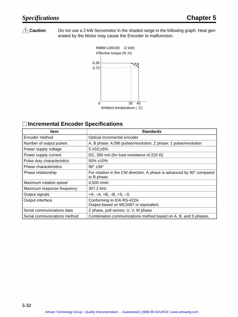
!
5-32
Caution Do not use a 2-kW Servomotor in the shaded range in the following graph. Heat gen-erated by the Motor may cause the Encoder to malfunction.
R88M-U2K030 (2 kW)Effective torque (Nm)
Ambient temperature (C)
ÍÍÍÍÍÍÍÍÍÍÍÍÍÍÍÍÍÍÍÍÍÍÍÍÍÍÍÍÍÍÍÍÍÍÍÍÍÍÍÍÍÍÍÍÍÍÍÍÍ
6.365.72
0 30 40
Incremental Encoder SpecificationsItem Standards
Encoder method Optical incremental encoder
Number of output pulses A, B phase: 4,096 pulses/revolution, Z phase: 1 pulse/revolution
Power supply voltage 5 VDC±5%
Power supply current DC, 350 mA (for load resistance of 220 Ω)
Pulse duty characteristics 50% ±10%
Phase characteristics 90° ±36°Phase relationship For rotation in the CW direction, A phase is advanced by 90° compared
to B phase.Maximum rotation speed 4,500 r/min
Maximum response frequency 307.2 kHz
Output signals +A, –A, +B, –B, +S, –S
Output interface Conforming to EIA RS-422A.Output based on MC3487 or equivalent.
Serial communications data Z phase, poll sensor, U, V, W phase
Serial communications method Combination communications method based on A, B, and S phases.
Specifications Chapter 5
Artisan Technology Group - Quality Instrumentation ... Guaranteed | (888) 88-SOURCE | www.artisantg.com

5-33
Absolute Encoder SpecificationsItem Standards
Encoder method Optical absolute encoder
Number of output pulses A, B phase: 8,192 pulses/revolution, Z phase: 1 pulse/revolution
Maximum rotational amount ±99,999 revolution
Power supply voltage 5 VDC±5%
Power supply current DC, 400 mA (for load resistance of 220 Ω)
Applicable battery voltage 3.6 VDC
Battery consumption current 10 µA (At backup or rotation stop.)
Pulse duty characteristics 50% ±10%
Phase characteristics 90° ±36°Phase relationship For rotation in the CW direction, A phase is advanced by 90° compared
to B phase.Maximum rotation speed 4,500 r/min
Maximum response frequency 614.4 kHz
Output signals +A, –A, +B, –B, +Z, –Z,
Output interface Conforming to EIA RS-422A.Output based on SN75158 or equivalent.
Absolute-value communicationsdata
Rotation amountAbsolute position within rotation (output only when power is supplied)
5-2-4 H-series Servomotors
General SpecificationsItem Specifications
Ambient operating temperature 0 to 40°CAmbient operating humidity 35% to 85% RH (with no condensation)
Ambient storage temperature –10 to 75°CAmbient storage humidity 35% to 85% RH (with no condensation)
Storage and operating atmo-sphere
No corrosive gasses.
Run position All directions
Insulation grade Type B
Structure Totally-enclosed self-cooling
Protective structure IP-52Cannot be used in environment with water-soluble cutting fluids.
Vibration grade V-15 (JEC2121)
Mounting method Flange-mounting
Note 1. The above items reflect individual evaluation testing. The results may differ under com-pounded conditions.
Note 2. The Servomotor cannot be used in a misty atmosphere.
Note 3. The drip-proofing specifications are covered by IP-54. (Models with drip-proof specificationsprovide drip-proofing on Servomotors with oil seals.)
Specifications Chapter 5
Artisan Technology Group - Quality Instrumentation ... Guaranteed | (888) 88-SOURCE | www.artisantg.com

5-34
Performance Characteristics
Item Unit R88M-H05030
R88M-H10030
R88M-H20030
R88M-H30030
R88M-H50030
R88M-H75030
R88M-H1K130
Rated output(See note.)
W 50 100 200 300 500 750 1100
Rated torque(S )
Nm 0.16 0.32 0.64 0.95 1.59 2.39 3.50q(See note.) kgfcm 1.62 3.25 6.50 9.74 16.2 24.4 35.7
Rated rotationspeed
r/min 3,000
Momentarymaximum rota-tion speed
r/min 4,000
Momentarymaximum
Nm 0.48 0.95 1.91 2.86 4.76 7.17 8.62maximumtorque (Seenote.)
kgfcm 4.86 9.74 19.5 29.2 48.6 73.2 88
Rotor inertia kgm2
(GD2/4)0.14 ×10–4
0.22 ×10⁻⁴
0.44 ×10⁻⁴
0.65 ×10⁻⁴
2.5 × 10⁻⁴ 4.1 × 10⁻⁴ 5.7 × 10⁻⁴
kgfcms2
1.4 × 10⁻⁴ 2.2 × 10⁻⁴ 4.5 × 10⁻⁴ 6.6 × 10⁻⁴ 26 × 10–4 42 × 10–4 58 × 10–4
Torqueconstant (See
Nm/A 0.22 0.35 0.43 0.49 0.43 0.47 0.59constant (Seenote.) kgfcm/A 2.2 3.6 4.4 5.0 4.4 4.8 6.0
Induced volt-age constant(See note.)
mV/(r/min)
23 37 45 52 45 50 62
Power rate(See note.)
kW/s 1.8 4.7 9.1 14 9.7 14 21
Mechanicaltime constant
ms 6.9 2.7 2.3 1.7 2.2 1.4 1.3
Winding resis-tance
Ω 24 16 10 6.1 1.6 0.74 0.80
Winding im-pedance
mH 51 43 38 28 10 6.6 6.9
Electrical timeconstant
ms 2.1 2.7 3.8 4.5 6.5 9.0 8.6
Momentary al-lowable radial
N 147 343 637 834lowable radialload kgf 15 35 65 85
Momentary al-lowable thrust
N 196 275 490 490lowable thrustload kgf 20 28 50 50
Allowable ra-di l l d
N 103 113 186 196 353 373 441dial load kgf 10.5 11.5 19.0 20.0 36.0 38.0 45.0
Al-l
A N 29 78 118 147low-able
kgf 3.0 8.0 12.0 15.0ablethrust B N 29 78 118 147thrustload kgf 3.0 7.5 11.0 13.0
Weight
With-outbrake
kg Approx.0.9
Approx.1.1
Approx.1.8
Approx.2.2
Approx.4.3
Approx.5.6
Approx.6.8
Withbrake
kg Approx.1.4
Approx.1.6
Approx.2.6
Approx.3.0
Approx.6.5
Approx.7.8
Approx.9.0
Specifications Chapter 5
Artisan Technology Group - Quality Instrumentation ... Guaranteed | (888) 88-SOURCE | www.artisantg.com

5-35
Item R88M-H1K130
R88M-H75030
R88M-H50030
R88M-H30030
R88M-H20030
R88M-H10030
R88M-H05030
Unit
Radiationshield dimen-sions
Material:A1
t6 x 150 t6 x 250 t12 x 250
ApplicablePosition Driver(FND )
200-Vinput
X06H- X12H- X25H-
(FND-) 100-Vinput
X06L- X12L- --- --- --- ---
Brakespec-ifi
Brakeinertia
kgm2
(GD2/4)0.02 x 10–4 0.05 x 10⁻⁴ 0.5 x 10⁻⁴
ifica-tions
kgfcms2
0.2 x 10⁻⁴ 0.5 x 10⁻⁴ 5 x 10⁻⁴
Excita-tionvoltage
V 24 VDC ±10% (No polarity)
Powercon-sump-tion
W (at20°C)
10 11 22
Staticfriction
Nm 0.5 min. 1.5 min. 5.4 min.frictiontorque kgfcm 5 min. 15 min. 55 min.
Ab-sorp-tiontime
ms 50 max. (reference value)
Re-leasetime
ms 30 max. (reference val-ue)
50 max. (reference value)
Back-lash
(Refer-ence val-ue)
±1.2° ±0.9° ±0.7°
Rating --- Continuous
Insula-tiongrade
--- Type F
Note 1. The brakes are the non-excitation type. (When excitation voltage is added, it is cleared.)
Note 2. For motors with brakes, increase the size of the radiation shield by 100 mm (example: t6 x250 → t6 x 350).
Note 3. The allowable radial load indicates the value at the center of the shaft (i.e., 1/2 of the outputshaft length). (See the diagram below.)
Radial load
Thrust loadBA
Note 4. The allowable thrust load varies depending on the shaft direction.
Note 5. The allowable radial load and the allowable thrust load are the values determined by taking aservice life of 30,000 hours at normal usage as the standard.
Specifications Chapter 5
Artisan Technology Group - Quality Instrumentation ... Guaranteed | (888) 88-SOURCE | www.artisantg.com

5-36
Note 6. H-series Servomotors can be used only with Position Driver software version 4.01 (Septem-ber 1997) or later.
Torque and Rotation Speed Characteristics (Standard Cable: 3 m; 200/100-VAC Input)
Specifications Chapter 5
Artisan Technology Group - Quality Instrumentation ... Guaranteed | (888) 88-SOURCE | www.artisantg.com

5-37
R88M-H05030 (50 W) R88M-H10030 (100 W) R88M-H20030 (200 W)
R88M-H30030 (300 W) R88M-H50030 (500 W) R88M-H75030 (750 W)
R88M-H1K130 (1100 W)
Short-term op-eration area(within 1 s)
Continuous op-eration area
Short-term op-eration area(within 1 s)
Continuous op-eration area
Short-term opera-tion area (within 1 s)
Continuous op-eration area
Short-term operation area(within 1 s)
Continuous op-eration area
Short-term operation area(within 1 s)
Continuous op-eration area
Continuous op-eration area
Short-term operation area(within 1 s)
Short-term operation area(within 1 s)
Continuous op-eration area
(r/min) (r/min) (r/min)
(r/min) (r/min) (r/min)
(r/min)
Specifications Chapter 5
Artisan Technology Group - Quality Instrumentation ... Guaranteed | (888) 88-SOURCE | www.artisantg.com

5-38
Encoder SpecificationsItem Standards
Encoder method A, B, Z phase: Magnetic incremental encoder with MR elements
Number of output pulses A, B phase: 2,000 pulses/revolution, Z phase: 1 pulse/revolution
Power supply voltage 5 VDC±5%
Pulse duty characteristics 50% ±10%
Phase characteristics 90° ±40°Phase relationship For rotation in the CW direction, A phase is advanced by 90° compared
to B phase.Maximum rotation speed 4,000 r/min
Maximum response frequency 133.3 kHz
Output signals +A, –A, +B, –B, +S, –S
Output interface Conforming to EIA RS-422A. Output based on AM26LS31CN or equivalent.
Serial communications data Z phase, poll sensor, U, V, W phase
Serial communications method Manchester code
5-2-5 M-series Servomotors
General SpecificationsItem Specifications
Ambient operating temperature 0 to 40°CAmbient operating humidity 35% to 85% RH (with no condensation)
Ambient storage temperature –10 to 75°CAmbient storage humidity 35% to 85% RH (with no condensation)
Storage and operating atmo-sphere
No corrosive gasses.
Run position All directions
Insulation grade Type F (JIS C4004)
Structure Totally-enclosed self-cooling
Protective structure IP-42 (JEM1030)Cannot be used in environment with water-soluble cutting fluids.
Vibration grade V-15 (JEC2121)
Mounting method Flange-mounting
Note 1. The above items reflect individual evaluation testing. The results may differ under com-pounded conditions.
Note 2. The Servomotor cannot be used in a misty atmosphere.
Note 3. The drip-proofing specifications are covered by IP-44. (Models with drip-proof specificationsprovide drip-proofing on Servomotors with oil seals.)
Specifications Chapter 5
Artisan Technology Group - Quality Instrumentation ... Guaranteed | (888) 88-SOURCE | www.artisantg.com

5-39
Performance Characteristics
1,200 r/minItem Unit R88M
-M20012R88M
-M40012R88M
-M70012R88M
-M1K112R88M
-M1K412R88M
-M1K812
Rated output(See note.)
W 200 400 700 1,100 1,400 1,800
Rated torque(S )
Nm 1.59 3.18 5.57 8.75 11.1 14.3q(See note.) kgfcm 16.2 32.5 56.8 89.3 114 146
Rated rotationspeed
r/min 1,200
Momentary maxi-mum rotationspeed
r/min 1,300
Momentary maxi-mum torque (See
Nm 4.3 7.4 17.6 16.7 30.4 44.1mum torque (Seenote.) kgfcm 44.0 75.0 180 170 310 450
Rated current(See note.)
A (rms) 2.1 2.9 4.0 6.6 8.4 9.3
Momentary maxi-mum current(See note.)
A (rms) 7.1 7.1 14.2 14.2 28.3 35.4
Rotor inertia kgm2
(GD2/4)6.3 × 10–4 9.8 × 10⁻⁴ 1.6 × 10⁻³ 4.2 × 10⁻³ 4.9 × 10⁻³ 6.5 × 10⁻³
kgfcms2 6.4 × 10⁻³ 1.0 × 10⁻² 1.6 × 10⁻² 4.3 × 10⁻² 5.0 × 10⁻² 6.6 × 10⁻²
Torque constant(S )
Nm/A 0.74 1.10 1.40 1.32 1.32 1.53q(See note.) kgfcm/A 7.6 11.2 14.3 13.5 13.5 15.6
Induced voltageconstant (Seenote.)
mV/(r/min)
53 72 88 82 83 92
Power rate (Seenote.)
kW/s 4.0 10 20 18 25 32
Mechanical timeconstant
ms 7.3 3.5 2.3 3.1 2.8 1.9
Winding resis-tance
Ω 9.8 6.4 4.2 1.9 1.5 1.0
Winding imped-ance
mH 70 65 50 20 40 27
Electrical timeconstant
ms 7.1 10.1 11.8 10 26 26
Momentary al-lowable radial
N 880 940 1,000 2,040 2,100 2,190lowable radialload kgf 90 96 102 208 214 223
Momentary al-lowable thrust
N 2,380 2,380 2,380 5,390 5,390 5,390lowable thrustload kgf 243 243 243 550 550 550
Allowable radialload
N 480 (560) 519 (600) 548 (640) 1,029(1,190)
1,058(1,230)
1,107(1,270)
kgf 49 (57) 53 (61) 56 (65) 105 (121) 108 (125) 113 (130)
Allowable thrustl d
N 68 (88) 58 (78) 58 (69) 156 (190) 147 (180) 127 (160)load kgf 7 (9) 6 (8) 6 (7) 16 (19) 15 (18) 13 (16)
Weight Withoutbrake
kg Approx. 6.5 Approx. 9.0 Approx. 14 Approx. 22 Approx. 26 Approx. 34
Withbrake
kg Approx. 7.1 Approx. 10 Approx. 15 Approx. 24 Approx. 28 Approx. 38
Specifications Chapter 5
Artisan Technology Group - Quality Instrumentation ... Guaranteed | (888) 88-SOURCE | www.artisantg.com

5-40
Item R88M-M1K812
R88M-M1K412
R88M-M1K112
R88M-M70012
R88M-M40012
R88M-M20012
Unit
Radiation shielddimensions
Material:FE (Seenote 4.)
t15 x 250 t20 x 300 t20 x 400
Applicable Posi-tion Driver(FND )
200-V in-put
X12H- X25H- X50H-
(FND-) 100-V in-put
X12L- ---
Brakespeci-fi
Brakeinertia
kgm2
(GD2/4)1.9 x 10–5 3.2 x 10⁻⁵ 6.8 x 10⁻⁵ 2.9 x 10⁻⁴ 3.0 x 10⁻⁴
fica-tions
kgfcms2 1.9 x 10⁻⁴ 3.3 x 10⁻⁴ 6.9 x 10⁻⁴ 2.9 x 10⁻³ 3.1 x 10⁻³tions
Excita-tionvoltage
V 24 VDC ±10% (No polarity)
Powercon-sump-tion
W (at20°C)
9.8 15 18 22
Currentcon-sump-tion
A (at20°C)
0.41 0.63 0.76 0.92
Staticfriction
Nm 2.0 min. 3.9 min. 7.8 min. 16 min. 29 min.frictiontorque kgfcm 20 min. 40 min. 80 min. 160 min. 300 min.
Absorp-tiontime(Seenote 3.)
ms 25 max. 35 max. 40 max. 60 max. 90 max.
Releasetime(Seenote 3.)
ms 15 max. 15 max. 20 max. 40 max. 35 max.
Back-lash
(Referencevalue)
±0.36° ±0.32° ±0.27° ±0.24° ±0.21°
Rating --- Continuous
Insula-tiongrade
--- Type B
Note 1. The brakes are the non-excitation type. (When excitation voltage is added, it is cleared.)
Note 2. The operation time measurement is the measured value with a surge killer installed.
Note 3. For Servomotors with brakes, increase the dimensions of the radiation shield by 50 mm each.(For example: t15 x 250 becomes t15 x 300.)
Note 4. The allowable radial load indicates the value at the center of the shaft (i.e., 1/2 of the outputshaft length). (See the diagram below.)
Radial loadThrust load
Output shaft center
Specifications Chapter 5
Artisan Technology Group - Quality Instrumentation ... Guaranteed | (888) 88-SOURCE | www.artisantg.com

5-41
Note 5. The allowable radial load and the allowable thrust load are the values determined by taking aservice life of 30,000 hours at normal usage as the standard (or 20,000 hours for the items inparentheses).
Note 6. M-series 1,200-r/min, 1,100 to 1,800-W Servomotors can be used only with Position Driversoftware version 4.04 (April 1999) or later.
2,000 r/minItem Unit R88M
-M20020R88M
-M40020R88M
-M70020R88M
-M1K120R88M
-M1K820R88M
-M2K220
Rated output(See note.)
W 200 400 700 1,100 1,800 2,200
Rated torque(S )
Nm 0.955 1.91 3.34 5.25 8.58 10.5q(See note.) kgfcm 9.74 19.5 34.1 53.6 87.6 107
Rated rotationspeed
r/min 2,000
Momentary maxi-mum rotationspeed
r/min 2,200
Momentary maxi-mum torque (See
Nm 3.3 3.9 9.6 12.9 21.6 26.5mum torque (Seenote.) kgfcm 34.0 40.0 98.0 132 220 270
Rated current(See note.)
A (rms) 2.0 3.3 4.1 5.5 8.6 12.3
Momentary maxi-mum current(See note.)
A (rms) 7.1 7.1 14.2 14.2 35.4 35.4
Rotor inertia kgm2
(GD2/4)1.6 × 10–4 6.3 × 10⁻⁴ 9.8 × 10⁻⁴ 1.6 × 10⁻³ 4.2 × 10⁻³ 4.9 × 10⁻³
kgfcms2 1.6 × 10⁻³ 6.4 × 10⁻² 1.0 × 10⁻² 1.6 × 10⁻² 4.3 × 10⁻² 5.0 × 10⁻²
Torque constant(S )
Nm/A 0.56 0.57 0.81 0.95 0.98 0.85q(See note.) kgfcm/A 5.7 5.8 8.3 9.7 10 8.7
Induced voltageconstant (Seenote.)
mV/(r/min)
35 40 50 62 50 53
Power rate (Seenote.)
kW/s 6.0 5.8 11 18 17 22
Mechanical timeconstant
ms 3.4 7.9 3.1 2.6 2.1 2.6
Winding resis-tance
Ω 10 6.1 3.1 2.2 0.70 0.58
Winding imped-ance
mH 46 32 25 21 17 14
Electrical timeconstant
ms 4.5 5.3 8.1 9.6 24 24
Momentary al-lowable radial
N 420 880 940 1,000 2,,040 2,100lowable radialload kgf 43 90 96 102 208 214
Momentary al-lowable thrust
N 1,180 2,380 2,380 2,380 5,390 5,390lowable thrustload kgf 120 243 243 243 550 550
Allowable radiall d
N 205 (250) 401 (470) 431 (500) 460 (540) 862 (1,000) 891 (1,030)load kgf 21 (25) 41 (48) 44 (51) 47 (55) 88 (102) 91 (105)
Allowable thrustl d
N 19 (29) 68 (88) 58 (78) 58 (69) 156 (190) 147 (180)
Specifications Chapter 5
Artisan Technology Group - Quality Instrumentation ... Guaranteed | (888) 88-SOURCE | www.artisantg.com

5-42
Item R88M-M2K220
R88M-M1K820
R88M-M1K120
R88M-M70020
R88M-M40020
R88M-M20020
Unit
load kgf 2 (3) 7 (9) 6 (8) 6 (7) 16 (19) 15 (18)
Weight Withoutbrake
kg Approx. 3.2 Approx. 6.5 Approx. 9.0 Approx. 14 Approx. 22 Approx. 26
Withbrake
kg Approx. 3.6 Approx. 7.1 Approx. 10 Approx. 15 Approx. 24 Approx. 28
Radiation shielddimensions
Material:FE (Seenote 4.)
t15 x 250 t20 x 300 t20 x 400
Applicable Posi-tion Driver(FND )
200-V in-put
X12H- X25H- X50H-
(FND-) 100-V in-put
X12L- ---
Brakespeci-fi
Brakeinertia
kgm2
(GD2/4)6.7 x 10–4 1.9 x 10⁻⁵ 3.2 x 10⁻⁵ 6.8 x 10⁻⁵ 2.8 x 10⁻⁴
fica-tions
kgfcms2 6.8 x 10⁻⁵ 1.9 x 10⁻⁴ 3.3 x 10⁻⁴ 6.9 x 10⁻³ 2.9 x 10⁻³tions
Excita-tionvoltage
V 24 VDC ±10% (No polarity)
Powercon-sump-tion
W (at20°C)
6.0 9.8 15 18
Currentcon-sump-tion
A (at20°C)
0.25 0.41 0.63 0.76
Staticfriction
Nm 0.98 min. 2.0 min. 3.9 min. 7.8 min. 16 min.frictiontorque kgfcm 10 min. 20 min. 40 min. 80 min. 160 min.
Absorp-tiontime(Seenote 3.)
ms 30 max. 25 max. 35 max. 40 max. 60 max. 90 max.
Releasetime(Seenote 3.)
ms 10 max. 15 max. 15 max. 20 max. 40 max. 35 max.
Back-lash
(Referencevalue)
±0.85° ±0.36° ±0.32° ±0.27° ±0.24° ±0.21°
Rating --- Continuous
Insula-tiongrade
--- Type B
Note 1. The brakes are the non-excitation type. (When excitation voltage is added, it is cleared.)
Note 2. The operation time measurement is the measured value with a surge killer installed.
Note 3. For Servomotors with brakes, increase the dimensions of the radiation shield by 50 mm each.(For example: t15 x 250 becomes t15 x 300.)
Specifications Chapter 5
Artisan Technology Group - Quality Instrumentation ... Guaranteed | (888) 88-SOURCE | www.artisantg.com

5-43
Note 4. The allowable radial load indicates the value at the center of the shaft (i.e., 1/2 of the outputshaft length). (See the diagram below.)
Radial loadThrust load
Output shaft center
Note 5. The allowable radial load and the allowable thrust load are the values determined by taking aservice life of 30,000 hours at normal usage as the standard (or 20,000 hours for the items inparentheses).
Note 6. M-series 2,000-r/min 1,100 to 2,200-W Servomotors can be used only with Position Driversoftware version 4.04 (April 1999) or later.
4,000 r/minItem Unit R88M
-M06040R88M
-M12040R88M
-M20040R88M
-M40040R88M
-M70040R88M
-M1K140R88M
-M2K040
Rated output(See note.)
W 60 120 200 400 700 1,100 2,000
Rated torque(S )
Nm 0.143 0.286 0.477 0.955 1.67 2.62 4.77q(See note.) kgfcm 1.46 2.92 4.87 9.74 17.0 26.8 48.7
Rated rotationspeed
r/min 4,000
Momentarymaximum rota-tion speed
r/min 4,400
Momentarymaximum torque
Nm 0.490 1.03 1.52 3.72 4.61 6.86 15.7maximum torque(See note.) kgfcm 5.00 10.5 15.5 38.0 47.0 70.0 160
Rated current(See note.)
A (rms) 1.5 1.8 2.1 3.4 4.6 5.0 10.5
Momentarymaximum cur-rent (See note.)
A (rms) 4.9 7.1 7.1 14.2 14.2 14.2 35.4
Rotor inertia kgm2
(GD2/4)2.9 × 10–5 4.1 × 10⁻⁵ 8.9 × 10⁻⁵ 1.6 × 10⁻⁴ 6.3 × 10⁻⁴ 9.8 × 10⁻⁴ 1.6 × 10⁻³
kgfcms2 3.0 × 10⁻⁴ 4.2 × 10⁻⁴ 9.1 × 10⁻⁴ 1.6 × 10⁻³ 6.4 × 10⁻³ 1.0 × 10⁻² 1.6 × 10⁻²
Torque constant(S )
Nm/A 0.15 0.19 0.23 0.28 0.35 0.52 0.46q(See note.) kgfcm/A 1.5 1.9 2.3 2.9 3.6 5.3 4.7
Induced voltageconstant (Seenote.)
mV/(r/min)
8.0 11.3 16.3 20 23.3 31.7 30
Power rate (Seenote.)
kW/s 0.70 2.0 2.6 5.8 4.4 7.0 15
Mechanical timeconstant
ms 6.6 3.8 7.6 4.5 7.4 3.2 2.8
Winding resis-tance
Ω 7.35 4.7 6.52 3.55 2.2 1.33 0.57
Winding imped-ance
mH 13 12 25 15 12 11 5.5
Electrical timeconstant
ms 1.8 2.6 3.8 4.2 5.5 8.3 9.6
Specifications Chapter 5
Artisan Technology Group - Quality Instrumentation ... Guaranteed | (888) 88-SOURCE | www.artisantg.com

5-44
Item R88M-M2K040
R88M-M1K140
R88M-M70040
R88M-M40040
R88M-M20040
R88M-M12040
R88M-M06040
Unit
Momentary al-lowable radial
N 140 160 370 420 880 940 1,000lowable radialload kgf 14 16 38 43 90 96 102
Momentary al-lowable thrust
N 440 440 1,180 1,180 2,380 2,380 2,380lowable thrustload kgf 45 45 120 120 243 243 243
Allowable radiall d
N 58 (69) 58 (78) 147 (180) 166 (200) 323 (370) 343 (400) 362 (420)load kgf 6 (7) 6 (8) 15 (18) 17 (20) 33 (38) 35 (41) 37 (43)
Allowable thrustl d
N 5 (6.9) 4 (5.9) 19 (29) 19 (29) 58 (69) 49 (59) 39 (49)load kgf 0.6 (0.7) 0.5 (0.6) 2 (3) 2 (3) 6 (7) 5 (6) 4 (5)
Weight Withoutbrake
kg Approx.1.2
Approx.1.6
Approx.2.3
Approx.3.2
Approx.6.5
Approx.9.0
Approx.14
Withbrake
kg Approx.1.4
Approx.1.8
Approx.2.7
Approx.3.6
Approx.7.1
Approx.10
Approx.15
Radiation shielddimensions
Material:FE (Seenote 4.)
t15 x 250 t20 x 300
Applicable Posi-tion Driver(FND )
200-V in-put
X12H- X25H- X50H-
(FND-) 100-V in-put
X12L- ---
Brakespeci-fi
Brakeinertia
kgm2
(GD2/4)1.5 x 10–6 6.7 x 10⁻⁶ 1.9 x 10⁻⁵ 3.2 x 10⁻⁵ 6.8 x 10⁻⁵
fica-tions
kgfcms2 1.5 x 10⁻⁵ 6.8 x 10⁻⁵ 1.9 x 10⁻⁴ 3.3 x 10⁻⁵ 6.9 x 10⁻⁵tions
Excita-tionvoltage
V 24 VDC ±10% (No polarity)
Powercon-sump-tion
W (at20°C)
5.0 6.0 9.8 15
Currentcon-sump-tion
A (at20°C)
0.21 0.25 0.41 0.63
Staticfriction
Nm 0.59 min. 0.98 min. 2.0 min. 3.9 min. 7.8 min.frictiontorque kgfcm 6 min. 10 min. 20 min. 40 min. 80 min.
Absorp-tiontime(Seenote 3.)
ms 25 max. 30 max. 25 max. 35 max. 40 max.
Re-leasetime(Seenote 3.)
ms 10 max. 10 max. 15 max. 15 max. 20 max.
Back-lash
(Referencevalue)
±1.2° ±0.85° ±0.36° ±0.32° ±0.27°
Rating --- Continuous
Insula-tiongrade
--- Type B
Specifications Chapter 5
Artisan Technology Group - Quality Instrumentation ... Guaranteed | (888) 88-SOURCE | www.artisantg.com

5-45
Note 1. The brakes are the non-excitation type. (When excitation voltage is added, it is cleared.)
Note 2. The operation time measurement is the measured value with a surge killer installed.
Note 3. For Servomotors with brakes, increase the dimensions of the radiation shield by 50 mm each.(For example: t15 x 250 becomes t15 x 300.)
Note 4. The allowable radial load indicates the value at the center of the shaft (i.e., 1/2 of the outputshaft length). (See the diagram below.)
Radial loadThrust load
Output shaft center
Note 5. The allowable radial load and the allowable thrust load are the values determined by taking aservice life of 30,000 hours at normal usage as the standard (or 20,000 hours for the items inparentheses).
Note 6. M-series 4,000 r/min 1,100 to 2,000 W Servomotors can be used only with Position Driversoftware version 4.04 (April 1999) or later.
Torque and Rotation Speed Characteristics (Standard Cable: 3 m;200/100-VAC Input)
1,200 r/min
R88M-M20012 R88M-M40012 R88M-M70012
Short-term op-eration area(within 1 s)
Continuousoperation area
Short-term op-eration area(within 1 s)
Continuousoperation area
Short-term op-eration area(within 1 s)
Continuousoperation area
(r/min) (r/min) (r/min)
R88M-M1K112 R88M-M1K412 R88M-M1K812
Short-term op-eration area(within 1 s)
Continuousoperation area
Short-term operation area(within 1 s)
Continuousoperation area
Short-term operation area(within 1 s)
Continuousoperation area
Specifications Chapter 5
Artisan Technology Group - Quality Instrumentation ... Guaranteed | (888) 88-SOURCE | www.artisantg.com

5-46
2,000 r/min
R88M-M20020 R88M-M40020 R88M-M70020
Short-termoperationarea (with-in 1 s)
Continuousoperation area
Short-termoperationarea (with-in 1 s)
Continuousoperation area
Short-termoperationarea (with-in 1 s)
Continuousoperation area
(r/min) (r/min) (r/min)
R88M-M1K120 R88M-M1K820 R88M-M2K220
Short-termoperationarea (with-in 1 s)
Continuousoperation area
Short-termoperationarea (with-in 1 s)
Continuousoperation area
Short-termoperationarea (with-in 1 s)
Continuousoperation area
Specifications Chapter 5
Artisan Technology Group - Quality Instrumentation ... Guaranteed | (888) 88-SOURCE | www.artisantg.com

5-47
4,000 r/min
R88M-M06040 R88M-M12040 R88M-M20040
R88M-M40040 R88M-M70040
Short-term op-eration area(within 1 s)
Continuousoperation area
Short-term op-eration area(within 1 s)
Continuousoperation area
Short-term op-eration area(within 1 s)
Continuousoperation area
Short-term op-eration area(within 1 s)
Continuousoperation area
Short-termoperationarea (with-in 1 s)
Continuousoperation area
(r/min) (r/min) (r/min)
(r/min) (r/min)
R88M-M1K140
R88M-M2K040
Short-term operation area(within 1 s)
Continuousoperation area
Short-termoperationarea (with-in 1 s)
Continuousoperation area
Resolver SpecificationsItem Standards
Accuracy Absolute accuracy: 0.18° max. (Ambient temperature: 25°C)
Origin signal 2 pulses/revolution
Specifications Chapter 5
Artisan Technology Group - Quality Instrumentation ... Guaranteed | (888) 88-SOURCE | www.artisantg.com

5-48
5-3 Cable Specifications
5-3-1 General Control Cables (DIO Position Drivers Only)
Cable ModelsModel Length (L) Outer diameter of sheath
FND-CCX001S 1 m 11.8 dia.
FND-CCS002S 2 m
Connection Configuration
SYSMAC C-series Programmable Controller FND-X-series Position Driver
43.5
39L
t=18
Specifications Chapter 5
Artisan Technology Group - Quality Instrumentation ... Guaranteed | (888) 88-SOURCE | www.artisantg.com

5-49
Wiring
PinNo.
Insulationcolor
Dot mark Dot mark color Signal name
1 Light brown – Black CCWL
2 Light brown – Red CWL
3 Yellow – Black ORG
4 Yellow – Red RUN
5 Light green – Black START
6 Light green – Red RESET
7 Gray – Black SEARCH
8 Gray – Red +JOG
9 White – Black –JOG
10 White – Red TEACH
11 Light brown – – Black P.IN0
12 Light brown – – Red P.IN1
13 Yellow – – Black P.IN2
14 Yellow – – Red P.IN3
15 Light green – – Black P.IN4
16 Light green – – Red P.IN5
17 Gray – – Black P.IN6
18 Gray – – Red P.IN7
19 White – – Black OGND
20 White – – Red STOP
21 Light brown – – – Black BO
22 Light brown – – – Red READY
23 Yellow – – – Black S.COM
24 Yellow – – – Red ORGSTP
25 Light green – – – Black T.COM
26 Light green – – – Red RUNON
27 Gray – – – Black INP
28 Gray – – – Red ALM
29 White – – – Black P.OUT0
30 White – – – Red P.OUT1
31 Light brown – – – – Black P.OUT2
32 Light brown – – – – Red P.OUT3
33 Yellow – – – – Black P.OUT4
34 Yellow – – – – Red P.OUT5
35 Light green – – – – Black P.OUT6
36 Light green – – – – Red +24V
Cable: UL2464, AWG24X18P
Note Connect the shield to the shield plate under the connector cover.
Specifications Chapter 5
2
4
6
8
10
12
14
16
18
1
3
5
7
9
11
13
15
17
20
22
24
26
28
30
32
34
36
19
21
23
25
27
29
31
33
35
Connector PinArrangement
Connector plug model:10136-3000VE(Sumitomo 3M)Connector case model:10336-52A0-008(Sumitomo 3M)
Artisan Technology Group - Quality Instrumentation ... Guaranteed | (888) 88-SOURCE | www.artisantg.com

5-50
5-3-2 Connector Terminal Board Conversion Unit Cables (DIOPosition Drivers Only)
Cable ModelsModel Length (L) Outer diameter of sheath
R88A-CTU001N 1 m 9.9 dia.
R88A-CTU002N 2 m
Connection Configuration
XW2B-40F5-P Connector Terminal BoardFND-X-series Position Driver
Specifications Chapter 5
Artisan Technology Group - Quality Instrumentation ... Guaranteed | (888) 88-SOURCE | www.artisantg.com

5-51
Wiring
Connector plug model: FCN-361J040-AU (Fujitsu)Connector case model: FCN-36C040-B (Fujitsu)
Cable:AWG24X18P, UL2464
Connector plug model: 10114-3000VE (Sumitomo 3M)Connector case model: 10314-52A0-008 (Sumitomo 3M)
36 +24VShell
Specifications Chapter 5
Artisan Technology Group - Quality Instrumentation ... Guaranteed | (888) 88-SOURCE | www.artisantg.com

5-52
5-3-3 External Control Signal Connecting Cables(CompoBus/S Position Drivers Only)
Connector-Terminal Block Conversion Unit Cable
CableModel Length (L) Outer diameter of sheath
FND-CTX002N 2 m 7.4 dia.
Connection Configuration
XW2B-20G4 or XW2B-20G5 Connector–Terminal Block FND-X-series Position Driver
30 29.5
16.1 2,000 39
t=6.1 t=12.7
Wiring
No.
1
2
3
4
5
6
7
8
9
10
11
12
13
14
15
16
17
18
19
20
No.
1
2
3
4
5
6
7
8
9
10
11
12
13
14
15
16
17
18
19
20
No.
7
1
2
3
4
8
14
Terminal block Connector
Symbol
+24 V
CCWL
CWL
ORG
STOP
BO
OGND
Connector model: XG4M-2030-T (OMRON) Contact plug model: 10114-3000VE (Sumitomo 3M)Contact case model: 10314-52A0-008 (Sumitomo 3M)
Specifications Chapter 5
Artisan Technology Group - Quality Instrumentation ... Guaranteed | (888) 88-SOURCE | www.artisantg.com
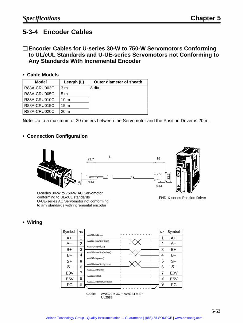
5-53
5-3-4 Encoder Cables
Encoder Cables for U-series 30-W to 750-W Servomotors Conformingto UL/cUL Standards and U-UE-series Servomotors not Conforming toAny Standards With Incremental Encoder
Cable ModelsModel Length (L) Outer diameter of sheath
R88A-CRU003C 3 m 8 dia.
R88A-CRU005C 5 mR88A-CRU010C 10 mR88A-CRU015C 15 m
R88A-CRU020C 20 m
Note Up to a maximum of 20 meters between the Servomotor and the Position Driver is 20 m.
Connection Configuration
U-series 30-W to 750-W AC Servomotorconforming to UL/cUL standardsU-UE-series AC Servomotor not conformingto any standards with incremental encoder
FND-X-series Position Driver
23.7L
t=14t=14
33.3
16
39
Wiring
A+A–
B+B–
S+S–
E0VE5VFG
1234
6789
5
No.
A+A–
B+B–
S+S–
E0VE5VFG
1234
6
789
5
No.AWG24 (blue)
AWG24 (white/blue)
AWG24 (yellow)
AWG24 (white/yellow)
AWG24 (green)
AWG24 (white/green)
AWG22 (black)
AWG22 (red)
AWG22 (green/yellow)
Symbol Symbol
Cable: AWG22 × 3C + AWG24 × 3PUL2589
Specifications Chapter 5
Artisan Technology Group - Quality Instrumentation ... Guaranteed | (888) 88-SOURCE | www.artisantg.com

5-54
For CableConnector housing model: 172161-1 (Nippon Amp) Contact plug model: 10120-3000VE (Sumitomo 3M)Connector socket contact model: 170365-1 (Nippon Amp) Contact case model: 10320-52A0-008 (Sumitomo 3M)Crimping tool: 724649-1Pulling tool: 724668-2
For MotorContact plug model: 172169-1 (Nippon Amp)Connector pin contact model: 170359-1 (Nippon Amp)
Encoder Cables for U-series 30-W to 750-W Servomotors Conformingto UL/cUL Standards with Absolute Encoder
Cable ModelsModel Length (L) Outer diameter of sheath
R88A-CSU003C 3 m 10.3 dia.
R88A-CSU005C 5 mR88A-CSU010C 10 mR88A-CSU015C 15 m
R88A-CSU020C 20 m
Note The maximum distance between the Servomotor and the Position Driver is 20 m.
Connection Configuration
U-series 30-W to 750-W AC Ser-vomotor conforming to UL/cULstandards with absolute encoder
FND-X-series Position Driver
23.7 L 39
t=14t=22.416
33.3
Specifications Chapter 5
Artisan Technology Group - Quality Instrumentation ... Guaranteed | (888) 88-SOURCE | www.artisantg.com

5-55
Wiring
AWG22 Red
AWG24 White/Blue
AWG24 Blue
AWG24 White/YellowAWG24 Yellow
AWG24 Green
AWG22 Black
AWG24 White/Green
AWG24 Purple
AWG24 White/Purple
AWG24 White/Gray
AWG24 White/Orange
AWG22 Green/YellowAWG24 Orange
1
2
3
4
5
6
7
8
10
11
12
13
14
15
9
16
17
18
19
14
15
1
4
8
9
10
13
12
20
A+
A–
B+
B–
Z+
Z–
E0V
E5V
ABS+
ABS–
NC
Reset
BAT–
BAT+
FG
A+
A–
B+
B–
Z+
Z–
E0V
E5V
ABS+
ABS–
(Reset)
BAT–
BAT+
FG
Cable: AWG22 × 3C + AWG24 × 6PUL2589
No. No. SymbolSymbol
For CableConnector housing model: 172163-1 (Nippon Amp) Contact plug model: 10120-3000VE (Sumitomo 3M)Connector socket contact model: 170365-1 (Nippon Amp) Contact case model: 10320-52A0-008 (Sumitomo 3M)Crimping tool: 724649-1Pulling tool: 724668-2
For MotorContact plug model: 172171-1 (Nippon Amp)Connector pin contact model: 170359-1 (Nippon Amp)
Encoder Cables for U-series 30-W to 750-W Servomotors andU-UE-series Servomotors Conforming to EC Directives withIncremental Encoders
Cable ModelsModel Length (L) Outer diameter of sheath
R88A-CRUD003C 3 m 8.0 dia.
R88A-CRUD005C 5 mR88A-CRUD010C 10 mR88A-CRUD015C 15 m
R88A-CRUD020C 20 m
Note The maximum distance between the Servomotor and the Position Driver is 20 m.
Specifications Chapter 5
Artisan Technology Group - Quality Instrumentation ... Guaranteed | (888) 88-SOURCE | www.artisantg.com

5-56
Connection Configuration
U-series 30-W to 750-W AC Servo-motor conforming to EC DirectivesU-UE-series AC Servomotor con-forming to EC Directives with incre-mental encoder
FND-X-series Position Driver
Wiring
AWG22 Red
AWG24 White/Blue
AWG24 Blue
AWG24 White/YellowAWG24 Yellow
AWG24 Green
AWG22 Black
AWG24 White/Green
AWG22 Green Yellow
1
2
3
4
5
6
7
8
9
16
17
18
19
14
15
1
4
20
Shell
A+
A–
B+
B–
S+
S–
E0V
E5V
FG
A+
A–
B+
B–
S+
S–
E0V
E5V
FG
Cable: AWG22 × 3C + AWG24 × 3PUL2589
No. No. SymbolSymbol
For CableConnector model: 17JE13090-02D8A (Daiichi Electronic Industries) Contact plug model: 10120-3000VE (Sumitomo 3M)Stand model: 17L-002A1 (Daiichi Electronic Industries) Contact case model: 10320-52A0-008 (Sumitomo 3M)
For MotorConnector model: 17JE23090-02D8A (Daiichi Electronic Industries)
Encoder Cables for U-series 30-W to 750-W Servomotors Conformingto EC Directives with Absolute Encoders
Cable ModelsModel Length (L) Outer diameter of sheath
R88A-CSUD003C 3 m 10.3 dia.
R88A-CSUD005C 5 mR88A-CSUD010C 10 mR88A-CSUD015C 15 mR88A-CSUD020C 20 m
Note The maximum distance between the Servomotor and the Position Driver is 20 m.
Specifications Chapter 5
Artisan Technology Group - Quality Instrumentation ... Guaranteed | (888) 88-SOURCE | www.artisantg.com

5-57
Connection Configuration
U-series 30-W to 750-W AC Ser-vomotor conforming to EC Direc-tives with absolute encoder
FND-X-series Position Driver
Wiring
AWG22 Red
AWG24 White/Blue
AWG24 Blue
AWG24 White/YellowAWG24 Yellow
AWG24 Green
AWG22 Black
AWG24 White/Green
AWG24 Purple
AWG24 White/Purple
AWG24 White/Gray
AWG24 White/Orange
AWG22 Green/YellowAWG24 Orange
1
2
3
4
5
6
7
8
10
11
12
13
14
15
9
16
17
18
19
14
15
1
4
8
9
10
13
12
20
A+
A–
B+
B–
Z+
Z–
E0V
E5V
ABS+
ABS–
NC
Reset
BAT–
BAT+
FG
A+
A–
B+
B–
Z+
Z–
E0V
E5V
ABS+
ABS–
(Reset)
BAT–
BAT+
FGCable: AWG22 × 3C + AWG24 × 6P
No. No. SymbolSymbol
Shell
For CableConnector model: 17JE13150-02D8A (Daiichi Electronic Industries) Contact plug model: 10120-3000VE (Sumitomo 3M)Stand model: 17L-002A1 (Daiichi Electronic Industries) Contact case model: 10320-52A0-008 (Sumitomo 3M)
For MotorConnector model: 17JE23150-02D8A (Daiichi Electronic Industries)
Specifications Chapter 5
Artisan Technology Group - Quality Instrumentation ... Guaranteed | (888) 88-SOURCE | www.artisantg.com

5-58
Encoder Cables for U-series 1-kW to 2-kW Servomotors withIncremental or Absolute Encoders
Note To conform to EC Directives, use the recommended connectors (refer to 2-1-2 Installation Condi-tions).
Cable ModelsModel Length (L) Outer diameter of sheath
R88A-CRUB003C 3 m 10.3 dia.
R88A-CRUB005C 5 mR88A-CRUB010C 10 m
R88A-CRUB015C 15 mR88A-CRUB020C 20 m
Note The maximum between the Servomotor and the Position Driver is 20 m.
Connection Configuration
U-series 1-kW to 2-kW AC Ser-vomotor
FND-X-series Position Driver
37.3
dia
.
Specifications Chapter 5
Artisan Technology Group - Quality Instrumentation ... Guaranteed | (888) 88-SOURCE | www.artisantg.com

5-59
Wiring
Signal Signal
Not used.
Not used.
Reset
Not used.
Not used.
Reset
Cable: AWG22 × 3C + AWG24 × 6P
AWG24 Blue
AWG24 White/Blue
AWG24 Yellow
AWG24 White/Yellow
AWG24 Green
AWG24 White/Green
AWG22 Black
AWG22 Red
AWG22 Purple
AWG24 Orange
AWG22 Green/Yellow
AWG24 White/Orange
AWG24 White/Gray
AWG24 White/Purple
Shell
For CableConnector plug model: MS3106B20-29S Connector plug model: 10120-3000VE (Sumitomo 3M)Cable clamp model: MS3057-12A Contact case model: 10320-52A0-008 (Sumitomo 3M)
For MotorReceptacle model: MS3102A20-29P
Encoder and Conversion Cables for H-series Servomotors
Encoder Cable ModelsModel Length (L) Outer diameter of sheath
R88A-CRH001C 1 m 8.0 dia.
R88A-CRH003C 3 mR88A-CRH005C 5 mR88A-CRH010C 10 mR88A-CRH015C 15 mR88A-CRH020C 20 m
R88A-CRH030C 30 m
Note Up to a maximum of 30 m between the Servomotor and the Position Driver is 20 m.
Specifications Chapter 5
Artisan Technology Group - Quality Instrumentation ... Guaranteed | (888) 88-SOURCE | www.artisantg.com

5-60
Connection Configuration
OMNUC H-series AC Servomotor FND-X-series Position DriverEncoder Cable Conversion Cable
11.7 L 40.5 40.5 500 39
t=14t=7.4 t=15 41
33.3
23
Wiring
Cable: AWG22 × 3P + 3CUL2589
Symbol SymbolRed
Black
Gray
Blue
Orange
Pink
Light blue
Yellow
Brown
Green
For CablePlug housing model: SMP-10V-NC (J.S.T. Mfg. Co., Ltd.) Contact plug model: XM2A-1501 (OMRON)Contact socket model: BHF-001GI-0.8BS (J.S.T. Mfg. Co., Ltd.) Contact case model: XM2S-1511 (OMRON)Crimping tool: YC-12Pulling tool: SMJ-06
For MotorReceptacle housing model: SMR-10V-N (J.S.T. Mfg. Co., Ltd.)Contact pin model: SYM-001G-0.6A (J.S.T. Mfg. Co., Ltd.)
Conversion Cable for H-series ServomotorsModel Length (L) Outer diameter of sheath
R88A-CRH0R5T 0.5 m 7.5 dia.
Specifications Chapter 5
Artisan Technology Group - Quality Instrumentation ... Guaranteed | (888) 88-SOURCE | www.artisantg.com

5-61
Wiring
A+A–
B+B–
S+S–
E5VE0VRG
8765
39
13
14
4
No.
A+A–
B+B–
S+S–
E5VE0V
FG
16171819
1541
14
No.
SG 15Cable: AWG22 × 4P
Symbol Symbol
20
Contact cover model: XM2S-1511 (OMRON) Contact plug model: 10120-3000VE (Sumitomo 3M)
Contact socket model: XM2D-1501 (OMRON) Contact case model: 10320-52A0-008 (Sumitomo 3M)
Fixture model: XM2Z-0001 (OMRON)
5-3-5 Resolver Cables
Resolver and Conversion Cables for M-series Servomotors
Cable ModelsModel Length (L) Outer diameter of sheath
R88M-CRM003N 3 m 8.2 dia.
R88M-CRM005N 5 mR88M-CRM010N 10 mR88M-CRM015N 15 mR88M-CRM020N 20 mR88M-CRM030N 30 m
R88M-CRM040N 40 mR88M-CRM050N 50 m
Note The maximum distance between the Servomotor and the Position Driver is 50 m.
Connection Configuration
OMNUC M-series AC Servomotor FND-X-series Position DriverResolver Cable Conversion Cable
58 L 35.8 35.8 500 39
t=14t=18
27 d
ia.
39.3
33.3
Specifications Chapter 5
Artisan Technology Group - Quality Instrumentation ... Guaranteed | (888) 88-SOURCE | www.artisantg.com

5-62
Wiring
Cable: AWG24 x 3P
Symbol Symbol
Shield
Shield
Shield
Red/White
Yellow/White
RedBlack
Yellow
Blue
Connector ModelFor CableSocket: JRC-16WPQ-7S (Hirose Electric) Connector plug model: MR-20F (Honda Tsushin Kogyo Co., Ltd.)Plug: JRC-16WPQ-CP10 (Hirose Electric) Connector case model: MR-20L (Honda Tsushin Kogyo Co., Ltd.)
For MotorReceptacle: JRC-16WRQ-7P (Hirose Electric)
Conversion Cable for M-series ServomotorsModel Length (L) Outer diameter of sheath
R88A-CRM0R5T 0.5 m 6.1 dia.
Wiring
R1 5
116
12
13181920
7
No.
8923
7
11
6
No.
R2S1S3
S2S4
SG1SG2SG3
R1R2S1S3
S2S4SG
Cable: AWG24 x 3P
Symbol Symbol
Relay case model: MR-20LK2G (Honda Tsushin Kogyo Co., Ltd.) Connector plug model: 10120-3000VE (Sumitomo 3M)
Connector model: MR-20RM (Honda Tsushin Kogyo Co., Ltd.) Connector case model: 10320-52A0-008 (Sumitomo 3M)
Specifications Chapter 5
Artisan Technology Group - Quality Instrumentation ... Guaranteed | (888) 88-SOURCE | www.artisantg.com
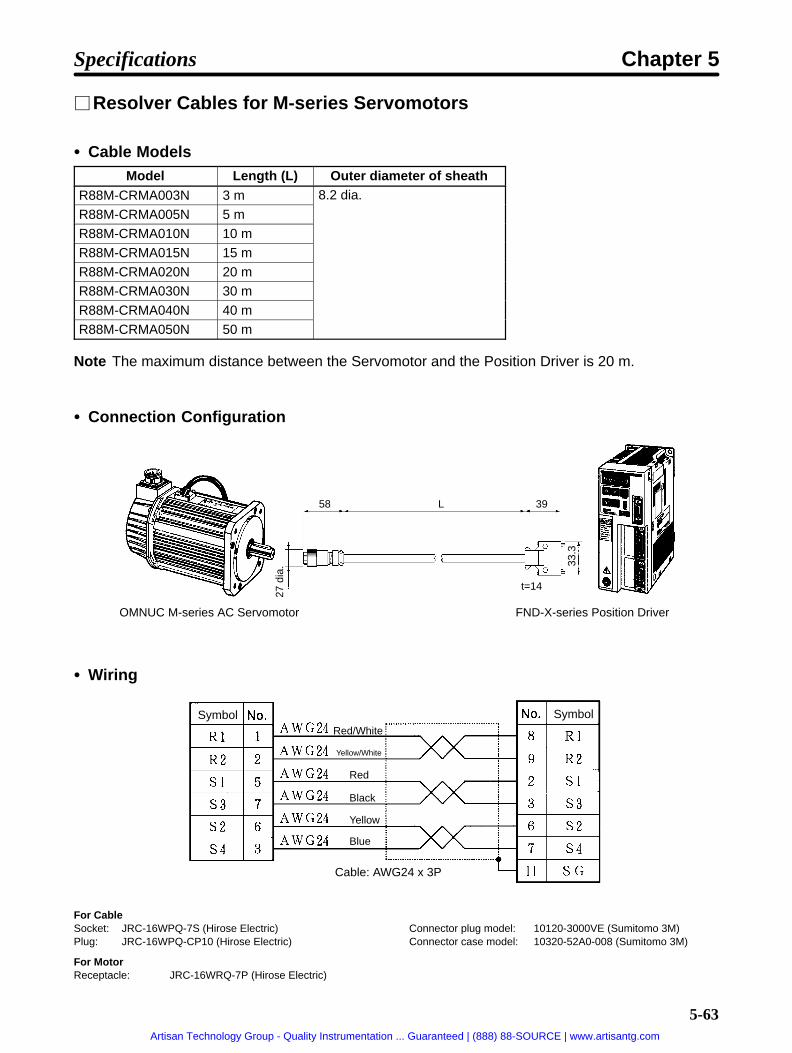
5-63
Resolver Cables for M-series Servomotors
Cable ModelsModel Length (L) Outer diameter of sheath
R88M-CRMA003N 3 m 8.2 dia.
R88M-CRMA005N 5 mR88M-CRMA010N 10 mR88M-CRMA015N 15 mR88M-CRMA020N 20 mR88M-CRMA030N 30 m
R88M-CRMA040N 40 mR88M-CRMA050N 50 m
Note The maximum distance between the Servomotor and the Position Driver is 20 m.
Connection Configuration
OMNUC M-series AC Servomotor FND-X-series Position Driver
58 L 39
t=14
27 d
ia. 33
.3
Wiring
Red/White
Yellow/White
Red
Black
Yellow
Blue
Symbol Symbol
Cable: AWG24 x 3P
For CableSocket: JRC-16WPQ-7S (Hirose Electric) Connector plug model: 10120-3000VE (Sumitomo 3M)Plug: JRC-16WPQ-CP10 (Hirose Electric) Connector case model: 10320-52A0-008 (Sumitomo 3M)
For MotorReceptacle: JRC-16WRQ-7P (Hirose Electric)
Specifications Chapter 5
Artisan Technology Group - Quality Instrumentation ... Guaranteed | (888) 88-SOURCE | www.artisantg.com

5-64
5-3-6 Power Cables
Power Cables for U-series 30-W to 750-W Servomotors Conforming toUL/cUL Standards and U-UE-series Servomotors not Conforming toAny Standards without Brake
Cable ModelsModel Length (L) Outer diameter of sheath
R88A-CAU003S 3 m 5.8 dia.
R88A-CAU005S 5 mR88A-CAU010S 10 mR88A-CAU015S 15 m
R88A-CAU020S 20 m
Note The maximum distance between the Servomotor and the Position Driver is 20 m.
Connection Configuration
FND-X-series Position DriverU-series 30-W to 750-W AC Servomotorconforming to UL/cUL standardsUE-series AC Servomotor not conformingto any standards without brake
Wiring
U-phase 1V-phase 2
W-phase 3
GR 4
Red
White
Blue
Green
Symbol No.
Cable: AWG20 × 4CUL2517
AWG20
AWG20
AWG20
AWG20
M4 Crimp terminals
For CableConnector housing model: 172159-1 (Nippon Amp)Connector socket contact model: 170366-1 (Nippon Amp)Crimping tool: 724651-1Pulling tool: 724668-2
For MotorContact plug model: 172167-1 (Nippon Amp)Connector pin contact model: 170359-1 (Nippon Amp) 30 to 100 W
170360-1 (Nippon Amp) 200 to 750 W
Specifications Chapter 5
Artisan Technology Group - Quality Instrumentation ... Guaranteed | (888) 88-SOURCE | www.artisantg.com

5-65
Power Cables for U-series 30-W to 750-W Servomotors Conforming toUL/cUL Standards and U-UE-series Servomotors not Conforming toAny Standards With Brake
Cable ModelsModel Length (L) Outer diameter of sheath
R88A-CAU003B 3 m 6.8 dia.
R88A-CAU005B 5 mR88A-CAU010B 10 mR88A-CAU015B 15 mR88A-CAU020B 20 m
Note The maximum distance between the Servomotor and the Position Driver is 20 m.
Connection Configuration
FND-X-series Position DriverU-series 30-W to 750-W AC Servomotorconforming to UL/cUL standardsU-UE-series AC Servomotor not conform-ing to any standards with brake
Wiring
U-phase 1V-phase 2
W-phase 3
GR 4
Red
White
Blue
Green
Brake 5
Brake 6
Black
Black
Symbol No.
Cable: AWG20 × 6C UL2517
M4 Crimp terminals
AWG20
AWG20
AWG20
AWG20
AWG20
AWG20
For CableConnector housing model: 172160-1 (Nippon Amp)Connector socket contact model: 170366-1 (Nippon Amp)Crimping tool: 724651-1Pulling tool: 724668-2
For MotorContact plug model: 172168-1 (Nippon Amp)Connector pin contact model: 170359-1 (Nippon Amp) 30 to 100 W
170360-1 (Nippon Amp) 200 to 750 W
Specifications Chapter 5
Artisan Technology Group - Quality Instrumentation ... Guaranteed | (888) 88-SOURCE | www.artisantg.com

5-66
Power Cables for U-series 30-W to 750-W and U-UE-seriesServomotors
Cable ModelsModel Length (L) Outer diameter of sheath Remarks
R88A-CAU001 1 m 5.8 dia. For models without brake
R88A-CAU01B 1 m 6.8 dia. For models with brake
Note 1. The power cable comes in units of 1 m. Cut the cable as required to make the specified length.
Note 2. The maximum distance between the Servomotor and the Position Driver is 20 m.
Connection Configuration
U-series 30-W to 750-W AC ServomotorU-UE-series AC Servomotor FND-X-series Position Driver
WiringR88A-CAU001
AC Servomotor
U-phase
V-phase
W-phase
Red
White
Blue
Green/Yellow
AWG20 Red
AWG20 White
AWG20 Blue
AWG20 Green
Position Driver
Cable: AWG20 × 4C UL2517
Specifications Chapter 5
Artisan Technology Group - Quality Instrumentation ... Guaranteed | (888) 88-SOURCE | www.artisantg.com

5-67
R88A-CAU01B
AC Servomotor
U-phase
V-phase
W-phase
Brake
Brake
Red
White
BlueGreen/Yellow
Red
Black
AWG20 Red
AWG20 White
AWG20 Blue
AWG20 Green
AWG20 Black
AWG20 Black
24 VDC ±10% (no polarity)Cable: AWG20 × 4C UL2517
Position Driver
Power Cables for U-series 1-kW to 2-kW Servomotors Without BrakeNote To conform to EC Directives, use the recommended connectors (refer to 2-1-2 Installation Condi-
tions).
Cable ModelsModel Length (L) Outer diameter of sheath
R88A-CAUB003S 3 m 14 dia.
R88A-CAUB005S 5 mR88A-CAUB010S 10 mR88A-CAUB015S 15 mR88A-CAUB020S 20 m
Note The maximum distance between the Servomotor and the Position Driver is 20 m.
Connection Configuration
U-series 1-kW to 2-kW AC Servomotorwithout brake FND-X-series Position Driver
34.1
dia
.
Specifications Chapter 5
Artisan Technology Group - Quality Instrumentation ... Guaranteed | (888) 88-SOURCE | www.artisantg.com

5-68
Wiring
Signal
U-phase
V-phase
W-phase
Red
White
Black
Green
Cable: AWG12 × 4C V5.5-4 Crimp terminals
AWG12
AWG12
AWG12
AWG12
For CableConnector plug model: MS3106B18-10SCable clamp model: MS3057-10A
For MotorReceptacle MS3102A18-10P
Power Cables for U-series 1-kW to 2-kW Servomotors With BrakeNote To conform to EC Directives, use the recommended connectors (refer to 2-1-2 Installation Condi-
tions).
Cable ModelsModel Length (L) Outer diameter of sheath
R88A-CAUB003S 3 m 16.5 dia.
R88A-CAUB005S 5 mR88A-CAUB010S 10 mR88A-CAUB015S 15 mR88A-CAUB020S 20 m
Note The maximum distance between the Servomotor and the Position Driver is 20 m.
Connection Configuration
U-series 1-kW to 2-kW AC Servomotorwith brake FND-X-series Position Driver
37.3
dia
.
Specifications Chapter 5
Artisan Technology Group - Quality Instrumentation ... Guaranteed | (888) 88-SOURCE | www.artisantg.com

5-69
Wiring
Signal
U-phase
V-phase
W-phase
Brake
Brake
Red
White
Black
Green
Brown
Yellow
Cable: AWG12 × 6C V5.5-4 Crimp terminals
AWG12
AWG12
AWG12
AWG12
AWG12
AWG12
For CableConnector plug model: MS3106B20-15SCable clamp model: MS3057-12A
For MotorReceptacle model: MS3102A20-15P
Power Cables for H-series Servomotors Without Brake
Cable ModelsModel Length (L) Wire size Outer diameter of sheath
R88A-CAH001S 1 m AWG18 5.8 dia.
R88A-CAH003S 3 mR88A-CAH005S 5 m
R88A-CAH010S 10 mR88A-CAH015S 15 m AWG16 11.3 dia.
R88A-CAH020S 20 mR88A-CAH030S 30 m
Note The maximum distance between the Servomotor and the Position Driver is 30 m.
Connection Configuration
FND-X-series Position DriverOMNUC H-series AC Servomotor(without brake)
L
Specifications Chapter 5
Artisan Technology Group - Quality Instrumentation ... Guaranteed | (888) 88-SOURCE | www.artisantg.com
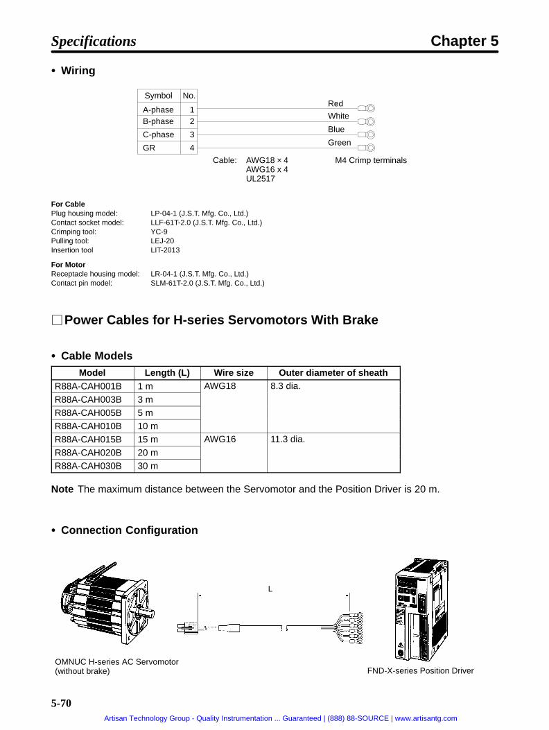
5-70
Wiring
A-phase 1B-phase 2
C-phase 3
GR 4
Red
White
Blue
Green
Symbol No.
Cable: AWG18 × 4AWG16 x 4UL2517
M4 Crimp terminals
For CablePlug housing model: LP-04-1 (J.S.T. Mfg. Co., Ltd.)Contact socket model: LLF-61T-2.0 (J.S.T. Mfg. Co., Ltd.)Crimping tool: YC-9Pulling tool: LEJ-20Insertion tool LIT-2013
For MotorReceptacle housing model: LR-04-1 (J.S.T. Mfg. Co., Ltd.)Contact pin model: SLM-61T-2.0 (J.S.T. Mfg. Co., Ltd.)
Power Cables for H-series Servomotors With Brake
Cable ModelsModel Length (L) Wire size Outer diameter of sheath
R88A-CAH001B 1 m AWG18 8.3 dia.
R88A-CAH003B 3 mR88A-CAH005B 5 mR88A-CAH010B 10 mR88A-CAH015B 15 m AWG16 11.3 dia.
R88A-CAH020B 20 mR88A-CAH030B 30 m
Note The maximum distance between the Servomotor and the Position Driver is 20 m.
Connection Configuration
FND-X-series Position DriverOMNUC H-series AC Servomotor(without brake)
L
Specifications Chapter 5
Artisan Technology Group - Quality Instrumentation ... Guaranteed | (888) 88-SOURCE | www.artisantg.com

5-71
Wiring
A-phase 1B-phase 2
C-phase 3
GR 4
Red
White
Blue
Green
Brake 5
Brake 6
Black
Black
Symbol No.
Cable: AWG18 × 6AWG16 x 4 + AWG20 x 2UL2517
M4 Crimp terminals
For CablePlug housing model: LP-06-1 (J.S.T. Mfg. Co., Ltd.)Contact socket model: LLF-61T-2.0 (J.S.T. Mfg. Co., Ltd.)Crimping tool: YC-9Pulling tool: LEJ-20Insertion tool: LIT-2013
For MotorReceptacle housing model: LR-06-1 (J.S.T. Mfg. Co., Ltd.)Contact pin model: SLM-61T-2.0 (J.S.T. Mfg. Co., Ltd.) A, B, C, GR
SLM-01T-2.0 (J.S.T. Mfg. Co., Ltd.) Brake
Specifications Chapter 5
Artisan Technology Group - Quality Instrumentation ... Guaranteed | (888) 88-SOURCE | www.artisantg.com

Chapter 6
CompoBus/SSpecifications
6-1 CompoBus/S Configuration Requirements
6-2 CompoBus/S Communications Specifications
6-3 Connecting a CompoBus/S System
6
Artisan Technology Group - Quality Instrumentation ... Guaranteed | (888) 88-SOURCE | www.artisantg.com

6-2
6-1 CompoBus/S Configuration Requirements
The CompoBus/S is configured as shown in the following diagram.
Master
Special flat cable
Slave Slave
Terminating resistance
T: T-branch methodM: Multi-drop method
Main line
Branch line
Power supply cable
Communicationspower supply
Slave
Slave Slave Slave
MastersThe Master controls the CompoBus/S and manages the external I/O for each of the Slaves. There isonly one Master per CompoBus/S System. The Master must be connected at the end of the mainline as shown in the above diagram.
SlavesSlaves process external I/O by communicating with the CompoBus/S and Master.
Main and Branch LinesThe main line is the cable that connects the furthest separated terminals. Branch lines are thecables that branch out from the main line.
CableWith the CompoBus/S, either special flat cable or VCTF cable can be used for communications.When flat cable is used, the communications power supply can be provided from the CompoBus/Scable. The configuration example in the above diagram uses flat cable. When VCTF cable is used,the power supply must be provided to the Slaves through a separate cable. (A communicationspower supply is not required for the FND-X.)
Connection MethodThe CompoBus/S has two methods for connecting Slaves: the T-branch method and the multi-dropmethod. With the T-branch method, Slaves are connected to branch lines that branch off from themain line. With the multi-drop method, Slaves are connected directly to the main line.
Termination ResistanceIn order to stabilize communications, it is necessary to install terminating resistance at the oppositeend of the main line from the Master. There are two types of terminating resistance: the connectortype with special flat cable, and the terminal block type.
CompoBus/S Specifications Chapter 6
Artisan Technology Group - Quality Instrumentation ... Guaranteed | (888) 88-SOURCE | www.artisantg.com
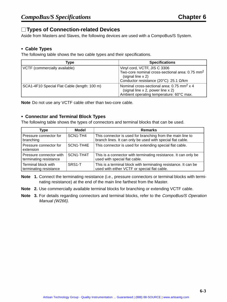
6-3
Types of Connection-related DevicesAside from Masters and Slaves, the following devices are used with a CompoBus/S System.
Cable TypesThe following table shows the two cable types and their specifications.
Type SpecificationsVCTF (commercially available) Vinyl cord, VCTF, JIS C 3306
Two-core nominal cross-sectional area: 0.75 mm2
(signal line x 2)Conductor resistance (20°C): 25.1 Ω/km
SCA1-4F10 Special Flat Cable (length: 100 m) Nominal cross-sectional area: 0.75 mm2 x 4(signal line x 2, power line x 2)
Ambient operating temperature: 60°C max.
Note Do not use any VCTF cable other than two-core cable.
Connector and Terminal Block TypesThe following table shows the types of connectors and terminal blocks that can be used.
Type Model RemarksPressure connector forbranching
SCN1-TH4 This connector is used for branching from the main line tobranch lines. It can only be used with special flat cable.
Pressure connector forextension
SCN1-TH4E This connector is used for extending special flat cable.
Pressure connector withterminating resistance
SCN1-TH4T This is a connector with terminating resistance. It can only beused with special flat cable.
Terminal block withterminating resistance
SRS1-T This is a terminal block with terminating resistance. It can beused with either VCTF or special flat cable.
Note 1. Connect the terminating resistance (i.e., pressure connectors or terminal blocks with termi-nating resistance) at the end of the main line farthest from the Master.
Note 2. Use commercially available terminal blocks for branching or extending VCTF cable.
Note 3. For details regarding connectors and terminal blocks, refer to the CompoBus/S OperationManual (W266).
CompoBus/S Specifications Chapter 6
Artisan Technology Group - Quality Instrumentation ... Guaranteed | (888) 88-SOURCE | www.artisantg.com

6-4
6-2 CompoBus/S Communications Specifications
This section provides details for CompoBus/S communications.
Communications SpecificationsItem Specifications
Communicationsmethod
Special CompoBus/S protocol
Communicationsbaud rate
750,000 baud
Modulation method Baseband method
Coding method Manchester coding method
Error control checks Manchester code check, frame length check, parity check
Cable used Vinyl cord, VCTF, JIS C 3306:Two-core nominal cross-sectional area: 0.75 mm2 (signal line x 2) (VCTF cable)
Special flat cable: 0.75 mm2 x 4 (signal line x 2, power line x 2)
Communicationsdi
VCTF Cabledistance Main line length Branch line length Total branch length
100 meters max. 3 meters max. 50 meters max.
Special Flat CableMain line length Branch line length Total branch length30 meters max. 3 meters max. 30 meters max.
Even when special flat cable is used, if no more than 16 Slavesare connected the main line length can be extended to a maxi-mum of 100 meters, and the total branch line length extendedto a maximum of 50 meters.
CompoBus/S Specifications Chapter 6
Artisan Technology Group - Quality Instrumentation ... Guaranteed | (888) 88-SOURCE | www.artisantg.com

6-5
Item SpecificationsMaximum numberof I/O Points, maxi-
When a C200HW-SRM21 or SRM1-C01/02 Master Unit is Used (for C200HX/HG/HE,C200HS)of I/O Points, maxi
mum number ofconnected Slaves,communications
Max. number of I/Opoints
Maximum numberof Slaves
Communicationscycle time
communicationscycle time IN: 64; OUT: 64 IN:8; OUT: 8 0.5 mscycle time
IN: 128; OUT: 128 IN: 16; OUT: 16 0.8 ms
When a CQM1 Master Unit is Used (For CQM1)Max. I/O points Maximum number
of SlavesCommunicationscycle time
IN: 64; OUT: 64 IN:8; OUT: 8(in 8-pt. mode)
0.5 ms
IN: 16; OUT: 16(in 4-pt. mode)
Cannot be used.*
IN: 32; OUT: 32 IN:4; OUT: 4(in 8-pt. mode)
0.5 ms
IN:8; OUT: 8(in 4-pt. mode)
Cannot be used.*
IN: 16; OUT: 16 IN:2; OUT: 2(in 8-pt. mode)
0.5 ms
IN:4; OUT: 4(in 4-pt. mode)
Cannot be used.*
*The 4-point mode cannot be used when an FND-X Position Driver is connected.
Note Only the high-speed communications mode is available with the FND-X.
Maximum Cable LengthThe “main line length” indicates the sum of the cable lengths between the Master Unit and the terminat-ing resistance connected to the farthest terminal from the main line. The “branch line length” indicatesthe length of any cable that branches off from the main line. The “total branch line length” indicates thesum of all the branch lines connected to the main line.
Main line length
Master
Branch line length
Total branch line length = L1 + L2 + L3 + L4 + L5
Slave Slave
Slave Slave Slave Slave Slave
Slave
Terminating resistance
The main line length, branch line length, and total branch line length depend on the type of cable usedand the number of Slaves connected, as shown in the following table.
Cable type Main line length Branch line length Total branch lengthVCTF cable 100 m max. 3 m max. 50 m max.
Special flat cable 30 m max. (See note 1.) 3 m max. 30 m max. (See note 1.)
Note 1. If no more than 16 Slaves are connected, the main line can be extended to a maximum of 100meters and the total branch line length to a maximum of 50 meters, just as with VCTF cable.
Note 2. Use either VCTF cable or special flat cable, and do not mix them.
CompoBus/S Specifications Chapter 6
Artisan Technology Group - Quality Instrumentation ... Guaranteed | (888) 88-SOURCE | www.artisantg.com

6-6
6-3 Connecting a CompoBus/S System
This manual only explains the CompoBus/S wiring related to FND-X-series Position Drivers. For moreinformation on connecting communications cables, wiring, Slaves, and so on, refer to the CompoBus/SOperation Manual (W266).
Preparing Communications CablesWhen connecting CompoBus/S cable to the Position Driver, follow the procedure shown below to pre-pare the cable.
1. Remove 5 to 7 mm of the insulation from the end of the communications cable (two wires), and se-curely twist the loose strands together for each of them.
5 to 7 mm
When using commercially-available VCTF cable, determine in advance which signal wire is to beused for BD H (high) and which for BD L (low).
For special flat cable, the signal wires are as shown below.
Communications power supply positive side (BS+): Brown
Communications data “high” side (BD H): Black
Communications data “low” side (BD L): White
Communications power supply negative side (BS–): Blue
2. When using special flat cable, the two power supply signal wires must be insulated.
Connecting Communications Cable1. Use a flat-head screwdriver to loosen the Position Driver’s two CompoBus/S communications ter-
minal screws, and remove the cable terminal block.
Cable terminal block
Screws
Note If the communications cable can be connected by simply tightening the screws, the cable terminalblock need not be removed.
2. Loosen the screws that fasten the signal wires to the cable terminal block, and carefully insert thetwo signal wires into their respective holes in the terminal block.
BD H
BD L
CompoBus/S Specifications Chapter 6
Artisan Technology Group - Quality Instrumentation ... Guaranteed | (888) 88-SOURCE | www.artisantg.com

6-7
Note Before inserting the signal wires, make sure that the screws have been loosened sufficiently. If ascrew is too tight when a wire is inserted, the wire may go into the gap in the rear of the fittinginstead of going into the proper place. If this happens, the wire cannot be securely fastened.
Signal wire insertion hole
Signal wire
Fitting
3. Tighten the cable terminal block screws to the proper torque of 0.5 Nm for each signal wire. Use asmall flat-head screwdriver with of uniform thickness. A normal screwdriver which is thin only at theend will not fit all the way in.
Small flat-head screwdriver of uniform thickness
Note The XW4Z-00C Screwdriver is available from OMRON especially for this task.
Shape of screwdriver’s head
Side view
0.6 mm
Front view
3.5 mm
The A1 Series by Phoenix Contact is recommended as a crimp-stye terminal for the cable. PhoenixContact also supplies the ZA3 as a special-purpose tool.
Crimp-style terminal Cable
Insert the cable and crimp it.
4. Be careful to match the directions of the cable terminal block and the Position Driver’s terminalblock, and insert the cable terminal block. Be sure to push it all the way in.
CompoBus/S Specifications Chapter 6
Artisan Technology Group - Quality Instrumentation ... Guaranteed | (888) 88-SOURCE | www.artisantg.com

6-8
Note Connect the cable with enough room so that it will not be pulled or bent. Also be sure not to placeheavy objects on the cable cord, or it may cause short circuiting.
5. Use a flat-head screwdriver to fasten the two screws that were loosened in step 1 to a torque of 0.2Nm.
CompoBus/S Specifications Chapter 6
Artisan Technology Group - Quality Instrumentation ... Guaranteed | (888) 88-SOURCE | www.artisantg.com

Chapter 7
Appendices
7-1 Standard Models
7-2 Parameter Settings Tables
7
Artisan Technology Group - Quality Instrumentation ... Guaranteed | (888) 88-SOURCE | www.artisantg.com

7-2
7-1 Standard Models
Position DriversSpecifications Model
DIO Type 200-VAC input 6 A FND-X06Hy
12 A FND-X12H25 A FND-X25H50 A FND-X50H
100-VAC input 6 A FND-X06L12 A FND-X12L
CompoBus/S Type 200-VAC input 6 A FND-X06H-SRTy
12 A FND-X12H-SRT25 A FND-X25H-SRT50 A FND-X50H-SRT
100-VAC input 6 A FND-X06L-SRT
12 A FND-X12L-SRT
Teaching BoxSpecifications Model
Teaching Box CVM1-PRO01ROM Cassette Common to FND-X, MC/NC Units CVM1-MP702
FND-X only CVM1-MP703Connecting Cable 2 m CV500-CN22Ag
4 m CV500-CN42A6 m CV500-CN62A
Note A ROM Cassette and Connecting Cable are required in order to use the Teaching Box.
External Regenerative ResistorsSpecification Model
Regeneration capacity: 100 W, 30Ω R88A-RR20030
Regeneration capacity: 200 W, 30Ω R88A-RR40030
General Control Cable (DIO Type)Specifications Model
Control Cable for FND-X 1 m FND-CCX001S
(With connector on one end.) 2 m FND-CCX002S
Connector-Terminal Board (DIO Type)Specification Model
Connector for Control Cable R88A-CNU01C
Connector-Terminal Board XW2B-40F5-PConnecting Cable forC T i l B d
1 m R88A-CTU001NgConnector-Terminal Board 2 m R88A-CTU002N
Appendices Chapter 7
Artisan Technology Group - Quality Instrumentation ... Guaranteed | (888) 88-SOURCE | www.artisantg.com
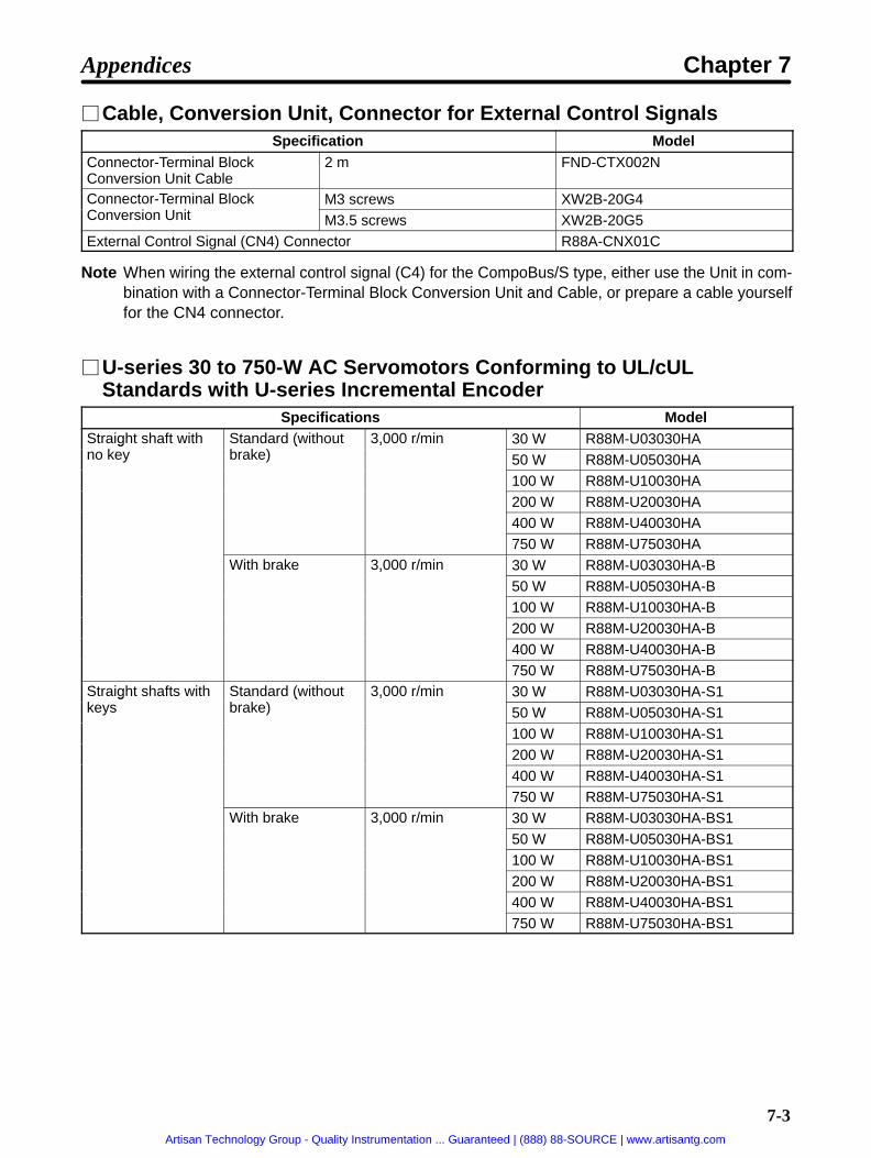
7-3
Cable, Conversion Unit, Connector for External Control SignalsSpecification Model
Connector-Terminal BlockConversion Unit Cable
2 m FND-CTX002N
Connector-Terminal BlockC i U i
M3 screws XW2B-20G4Conversion Unit M3.5 screws XW2B-20G5External Control Signal (CN4) Connector R88A-CNX01C
Note When wiring the external control signal (C4) for the CompoBus/S type, either use the Unit in com-bination with a Connector-Terminal Block Conversion Unit and Cable, or prepare a cable yourselffor the CN4 connector.
U-series 30 to 750-W AC Servomotors Conforming to UL/cULStandards with U-series Incremental Encoder
Specifications ModelStraight shaft with
kStandard (withoutb k )
3,000 r/min 30 W R88M-U03030HAgno key
(brake)
,
50 W R88M-U05030HA100 W R88M-U10030HA200 W R88M-U20030HA400 W R88M-U40030HA750 W R88M-U75030HA
With brake 3,000 r/min 30 W R88M-U03030HA-B,
50 W R88M-U05030HA-B100 W R88M-U10030HA-B200 W R88M-U20030HA-B400 W R88M-U40030HA-B750 W R88M-U75030HA-B
Straight shafts withk
Standard (withoutb k )
3,000 r/min 30 W R88M-U03030HA-S1gkeys
(brake)
,
50 W R88M-U05030HA-S1100 W R88M-U10030HA-S1200 W R88M-U20030HA-S1400 W R88M-U40030HA-S1750 W R88M-U75030HA-S1
With brake 3,000 r/min 30 W R88M-U03030HA-BS1,
50 W R88M-U05030HA-BS1
100 W R88M-U10030HA-BS1200 W R88M-U20030HA-BS1400 W R88M-U40030HA-BS1750 W R88M-U75030HA-BS1
Appendices Chapter 7
Artisan Technology Group - Quality Instrumentation ... Guaranteed | (888) 88-SOURCE | www.artisantg.com

7-4
U-series 30 to 750-W AC Servomotors Conforming to UL/cULStandards with U-series Absolute Encoder
Specifications ModelStraight shafts with
kStandard (withoutb k )
3,000 r/min 30 W R88M-U03030TAgno keys
(brake)
,
50 W R88M-U05030TA100 W R88M-U10030TA200 W R88M-U20030TA400 W R88M-U40030TA
750 W R88M-U75030TAWith brake 3,000 r/min 30 W R88M-U03030TA-B,
50 W R88M-U05030TA-B100 W R88M-U10030TA-B200 W R88M-U20030TA-B400 W R88M-U40030TA-B750 W R88M-U75030TA-B
Straight shafts withk
Standard (withoutb k )
3,000 r/min 30 W R88M-U03030TA-S1gkeys
(brake)
,
50 W R88M-U05030TA-S1100 W R88M-U10030TA-S1200 W R88M-U20030TA-S1400 W R88M-U40030TA-S1750 W R88M-U75030TA-S1
With brake 3,000 r/min 30 W R88M-U03030TA-BS1,
50 W R88M-U05030TA-BS1100 W R88M-U10030TA-BS1200 W R88M-U20030TA-BS1400 W R88M-U40030TA-BS1750 W R88M-U75030TA-BS1
U-series 30 to 750-W AC Servomotors Conforming to EC Directiveswith Incremental Encoder
Specifications ModelStraight shafts withk
Standard (withoutb k )
3,000 r/min 30 W R88M-U03030VA-S1gkeys
(brake)
,
50 W R88M-U05030VA-S1
100 W R88M-U10030VA-S1200 W R88M-U20030VA-S1400 W R88M-U40030VA-S1750 W R88M-U75030VA-S1
Standard (withb k )
3,000 r/min 30 W R88M-U03030VA-BS1(brake)
,
50 W R88M-U05030VA-BS1100 W R88M-U10030VA-BS1
200 W R88M-U20030VA-BS1400 W R88M-U40030VA-BS1750 W R88M-U75030VA-BS1
Appendices Chapter 7
Artisan Technology Group - Quality Instrumentation ... Guaranteed | (888) 88-SOURCE | www.artisantg.com

7-5
U-series 30 to 750-W AC Servomotors Conforming to EC Directiveswith Absolute Encoder
Specifications ModelStraight shafts with
kStandard (withoutb k )
3,000 r/min 30 W R88M-U03030XA-S1gno keys
(brake)
,
50 W R88M-U05030XA-S1100 W R88M-U10030XA-S1200 W R88M-U20030XA-S1400 W R88M-U40030XA-S1
750 W R88M-U75030XA-S1Standard (withb k )
3,000 r/min 30 W R88M-U03030XA-BS1(brake)
,
50 W R88M-U05030XA-BS1100 W R88M-U10030XA-BS1200 W R88M-U20030XA-BS1400 W R88M-U40030XA-BS1750 W R88M-U75030XA-BS1
U-UE-series AC Servomotors Not Conforming to Any Standards withIncremental Encoder
Specifications ModelStraight shafts withk
Standard (withoutb k )
3,000 r/min 100 W R88M-UE10030H-S1gkeys
(brake)
,
200 W R88M-UE20030H-S1400 W R88M-UE40030H-S1750 W R88M-UE75030H-S1
With brake 3,000 r/min 100 W R88M-UE10030H-BS1,
200 W R88M-UE20030H-BS1
400 W R88M-UE40030H-BS1750 W R88M-UE75030H-BS1
U-UE-series AC Servomotors Conforming to EC Directives withIncremental Encoder
Specifications ModelStraight shafts withk
Standard (withoutb k )
3,000 r/min 100 W R88M-UE10030V-S1gkeys
(brake)
,
200 W R88M-UE20030V-S1
400 W R88M-UE40030V-S1750 W R88M-UE75030V-S1
With brake 3,000 r/min 100 W R88M-UE10030V-BS1,
200 W R88M-UE20030V-BS1400 W R88M-UE40030V-BS1750 W R88M-UE75030V-BS1
Note When selecting a U-series or U-UE-series Servomotor, the Servomotor must be a 200-VAC type(HA/TA/VA/XA or H/A) even when the U/U-UE Servomotor is combined with a 100-VAC-inputPosition Driver. A 100-VAC-type Servomotor cannot be connected.
Appendices Chapter 7
Artisan Technology Group - Quality Instrumentation ... Guaranteed | (888) 88-SOURCE | www.artisantg.com

7-6
U-series 1 to 2-kW AC Servomotors Not Conforming to Any Standardswith Incremental Encoder
Specifications ModelStraight shafts with
kStandard (withoutb k )
3,000 r/min 1 kW R88M-U1K030Hgno keys
(brake)
,
1.5 kW R88M-U1K530H2 kW R88M-U2K030H
Standard (withb k )
3,000 r/min 1 kW R88M-U1K030H-B(brake)
,
1.5 kW R88M-U1K530H-B
2 kW R88M-U2K030H-BStraight shafts withk
Standard (withoutb k )
3,000 r/min 1 kW R88M-U1K030H-S1gkeys
(brake)
,
1.5 kW R88M-U1K530H-S12 kW R88M-U2K030H-S1
Standard (withb k )
3,000 r/min 1 kW R88M-U1K030H-BS1(brake)
,
1.5 kW R88M-U1K530H-BS1
2 kW R88M-U2K030H-BS1
U-series 1 to 2-kW AC Servomotors Not Conforming to Any Standardswith Absolute Encoder
Specifications ModelStraight shafts with
kStandard (withoutb k )
3,000 r/min 1 kW R88M-U1K030Tgno keys
(brake)
,
1.5 kW R88M-U1K530T
2 kW R88M-U2K030TStandard (withb k )
3,000 r/min 1 kW R88M-U1K030T-B(brake)
,
1.5 kW R88M-U1K530T-B2 kW R88M-U2K030T-B
U-series 1 to 2-kW AC Servomotors Conforming to EC Directives withIncremental Encoder
Specifications ModelStraight shafts withk
Standard (withoutb k )
3,000 r/min 1 kW R88M-U1K030V-S1gkeys
(brake)
,
1.5 kW R88M-U1K530V-S12 kW R88M-U2K030V-S1
Standard (withb k )
3,000 r/min 1 kW R88M-U1K030V-BS1(brake)
,
1.5 kW R88M-U1K530V-BS12 kW R88M-U2K030V-BS1
U-series 1 to 2-kW AC Servomotors Conforming to EC Directives withAbsolute Encoder
Specifications ModelStraight shafts withk
Standard (withoutb k )
3,000 r/min 1 kW R88M-U1K030X-S1gkeys
(brake)
,
1.5 kW R88M-U1K530X-S12 kW R88M-U2K030X-S1
Standard (withb k )
3,000 r/min 1 kW R88M-U1K030X-BS1(brake)
,
1.5 kW R88M-U1K530X-BS12 kW R88M-U2K030X-BS1
Appendices Chapter 7
Artisan Technology Group - Quality Instrumentation ... Guaranteed | (888) 88-SOURCE | www.artisantg.com

7-7
H-series AC Servomotors with Incremental EncoderSpecifications Model
Straight shafts withk
Standard (withoutb k )
3,000 r/min 50 W R88M-H05030gkeys
(brake)
,
100 W R88M-H10030200 W R88M-H20030300 W R88M-H30030500 W R88M-H50030
750 W R88M-H750301100 W R88M-H1K130
With brake 3,000 r/min 50 W R88M-H05030-B,
100 W R88M-H10030-B200 W R88M-H20030-B300 W R88M-H30030-B500 W R88M-H50030-B
750 W R88M-H75030-B1100 W R88M-H1K130-B
Appendices Chapter 7
Artisan Technology Group - Quality Instrumentation ... Guaranteed | (888) 88-SOURCE | www.artisantg.com

7-8
M-series AC Servomotors with Resolver
Specifications Model
Straight shafts withk
Standard (withoutb k )
1,200 r/min 200 W R88M-M20012gkeys
(brake)
,
400 W R88M-M40012700 W R88M-M700121100 W R88M-M1K1121400 W R88M-M1K412
1800 W R88M-M1K8122,000 r/min 200 W R88M-M20020,
400 W R88M-M40020700 W R88M-M700201100 W R88M-M1K1201800 W R88M-M1K8202200 W R88M-M2K220
4,000 r/min 60 W R88M-M06040,
120 W R88M-M12040200 W R88M-M20040400 W R88M-M40040700 W R88M-M700401100 W R88M-M1K140
2000 W R88M-M2K040With brake 1,200 r/min 200 W R88M-M20012-B,
400 W R88M-M40012-B700 W R88M-M70012-B1100 W R88M-M1K112-B1400 W R88M-M1K412-B1800 W R88M-M1K812-B
2,000 r/min 200 W R88M-M20020-B,
400 W R88M-M40020-B700 W R88M-M70020-B1100 W R88M-M1K120-B1800 W R88M-M1K820-B2200 W R88M-M2K220-B
4,000 r/min 60 W R88M-M06040-B,
120 W R88M-M12040-B200 W R88M-M20040-B400 W R88M-M40040-B700 W R88M-M70040-B1100 W R88M-M1K140-B2000 W R88M-M2K040-B
Note The 60-W and 120-W motor output shafts for the 4,000-r/min type are “A cut” (i.e., the cross-sec-
tion of the shaft is shaped like an “A ”).
Appendices Chapter 7
Artisan Technology Group - Quality Instrumentation ... Guaranteed | (888) 88-SOURCE | www.artisantg.com

7-9
Encoder Cable for U-series 30 to 750-W AC Servomotors Conformingto UL/cUL Standards
Specifications ModelFor Servomotors with incremental encoders. 3 m R88A-CRU003C
(With connectors on both sides.) 5 m R88A-CRU005C(With connectors on both sides.)10 m R88A-CRU010C15 m R88A-CRU015C20 m R88A-CRU020C
Cable only 1-m units R88A-CRU001For Servomotors with absolute encoders. 3 m R88A-CSU003C
(With connectors on both sides.) 5 m R88A-CSU005C(With connectors on both sides.)10 m R88A-CSU010C15 m R88A-CSU015C20 m R88A-CSU020C
Encoder Cable for U-series 30 to 750-W AC Servomotors Conformingto EC Directives
Specifications ModelFor Servomotors with incremental encoders. 3 m R88A-CRUD003C
(With connectors on both sides.) 5 m R88A-CRUD005C(With connectors on both sides.)10 m R88A-CRUD010C15 m R88A-CRUD015C20 m R88A-CRUD020C
Cable only 1-m units R88A-CRU001For Servomotors with absolute encoders. 3 m R88A-CSUD003C
(With connectors on both sides.) 5 m R88A-CSUD005C(With connectors on both sides.)10 m R88A-CSUD010C15 m R88A-CSUD015C20 m R88A-CSUD020C
Encoder Cable for U-UE-series AC Servomotors Not Conforming toAny Standards
Specifications ModelFor Servomotors with incremental encoders. 3 m R88A-CRU003C
(With connectors on both sides.) 5 m R88A-CRU005C(With connectors on both sides.)10 m R88A-CRU010C15 m R88A-CRU015C
20 m R88A-CRU020CCable only 1-m units R88A-CRU001
Appendices Chapter 7
Artisan Technology Group - Quality Instrumentation ... Guaranteed | (888) 88-SOURCE | www.artisantg.com
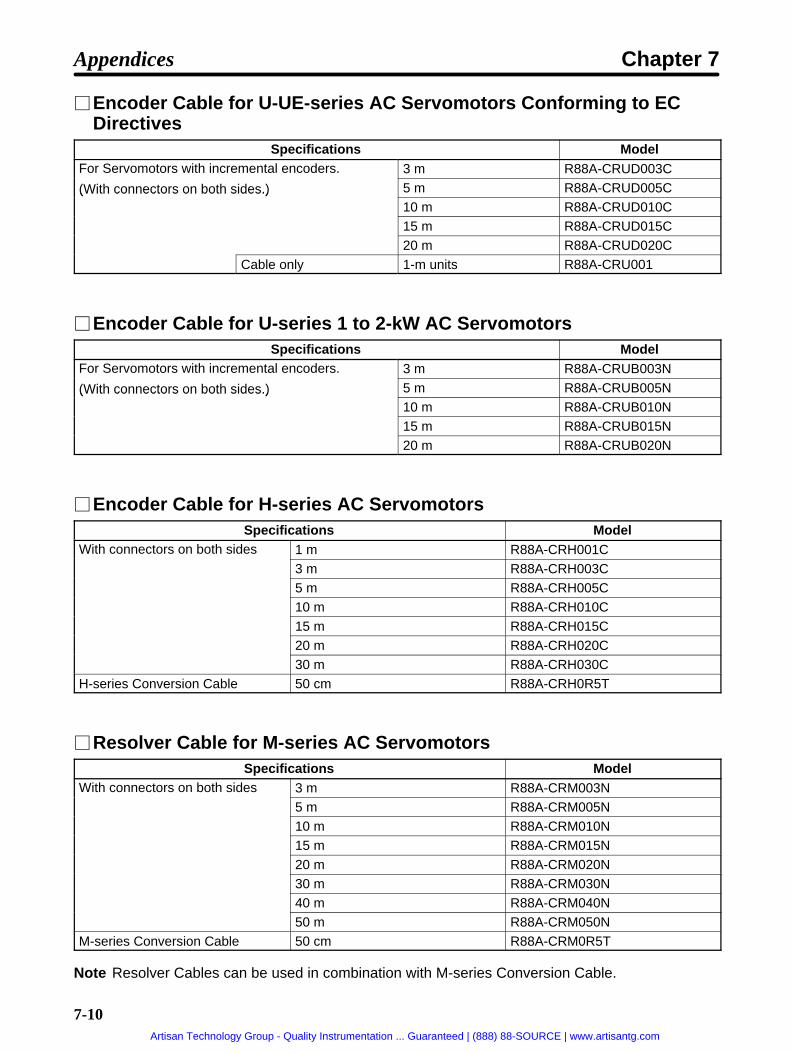
7-10
Encoder Cable for U-UE-series AC Servomotors Conforming to ECDirectives
Specifications ModelFor Servomotors with incremental encoders. 3 m R88A-CRUD003C
(With connectors on both sides.) 5 m R88A-CRUD005C(With connectors on both sides.)10 m R88A-CRUD010C15 m R88A-CRUD015C20 m R88A-CRUD020C
Cable only 1-m units R88A-CRU001
Encoder Cable for U-series 1 to 2-kW AC ServomotorsSpecifications Model
For Servomotors with incremental encoders. 3 m R88A-CRUB003N
(With connectors on both sides.) 5 m R88A-CRUB005N(With connectors on both sides.)10 m R88A-CRUB010N15 m R88A-CRUB015N20 m R88A-CRUB020N
Encoder Cable for H-series AC ServomotorsSpecifications Model
With connectors on both sides 1 m R88A-CRH001C3 m R88A-CRH003C5 m R88A-CRH005C10 m R88A-CRH010C
15 m R88A-CRH015C20 m R88A-CRH020C30 m R88A-CRH030C
H-series Conversion Cable 50 cm R88A-CRH0R5T
Resolver Cable for M-series AC ServomotorsSpecifications Model
With connectors on both sides 3 m R88A-CRM003N5 m R88A-CRM005N10 m R88A-CRM010N15 m R88A-CRM015N
20 m R88A-CRM020N30 m R88A-CRM030N40 m R88A-CRM040N50 m R88A-CRM050N
M-series Conversion Cable 50 cm R88A-CRM0R5T
Note Resolver Cables can be used in combination with M-series Conversion Cable.
Appendices Chapter 7
Artisan Technology Group - Quality Instrumentation ... Guaranteed | (888) 88-SOURCE | www.artisantg.com

7-11
Power Cable for U-series 30 to 750-W AC Servomotors Conforming toUL/cUL Standards
Specifications ModelCable with connector on both sides for Servomotor
i h b k3 m R88A-CAU003S
without brake 5 m R88A-CAU005S10 m R88A-CAU010S15 m R88A-CAU015S20 m R88A-CAU020S
Cable only 1-m units R88A-CAU001Cable with connector on both sides for Servomotor
i h b k3 m R88A-CAU003B
with brake 5 m R88A-CAU005B10 m R88A-CAU010B15 m R88A-CAU015B20 m R88A-CAU020B
Cable only 1-m units R88A-CAU01B
Power Cable for U-series 30 to 750-W AC Servomotors Conforming toEC Directives
Specifications ModelFor Servomotor without brake 1-m units R88A-CAU001
For Servomotor with brake 1-m units R88A-CAU01B
Note The above models are for the Cable only.
Power Cable for U-UE-series AC Servomotors Not Conforming to AnyStandards
Specifications ModelCable with connector on both sides for Servomotor
i h b k3 m R88A-CAU003S
without brake 5 m R88A-CAU005S10 m R88A-CAU010S15 m R88A-CAU015S20 m R88A-CAU020S
Cable only 1-m units R88A-CAU001Cable with connector on both sides for Servomotor
i h b k3 m R88A-CAU003B
with brake 5 m R88A-CAU005B10 m R88A-CAU010B15 m R88A-CAU015B20 m R88A-CAU020B
Cable only 1-m units R88A-CAU01B
Appendices Chapter 7
Artisan Technology Group - Quality Instrumentation ... Guaranteed | (888) 88-SOURCE | www.artisantg.com

7-12
Power Cable for U-UE-series AC Servomotors Conforming to ECDirectives
Specifications ModelFor Servomotor without brake 1-m units R88A-CAU001
For Servomotor with brake 1-m units R88A-CAU01B
Note The above models are for the Cable only.
Power Cable for U-series 1 to 2-kW AC ServomotorsSpecifications Model
Cable with connector on both sides for Servomotori h b k
3 m R88A-CAUB003Swithout brake 5 m R88A-CAUB005S
10 m R88A-CAUB010S15 m R88A-CAUB015S20 m R88A-CAUB020S
Cable with connector on both sides for Servomotori h b k
3 m R88A-CAUB003Bwith brake 5 m R88A-CAUB005B
10 m R88A-CAUB010B15 m R88A-CAUB015B20 m R88A-CAUB020B
Power Cable for H-series AC ServomotorsSpecifications Model
Cable with connector on one endf S i h b k
1 m R88A-CAH001Sfor Servomotor without brake 3 m R88A-CAH003S
5 m R88A-CAH005S10 m R88A-CAH010S15 m R88A-CAH015S20 m R88A-CAH020S
30 m R88A-CAH030SCable with connector on one endf S i h b k
1 m R88A-CAH001Bfor Servomotor with brake 3 m R88A-CAH003B
5 m R88A-CAH005B10 m R88A-CAH010B15 m R88A-CAH015B
20 m R88A-CAH020B30 m R88A-CAH030B
Appendices Chapter 7
Artisan Technology Group - Quality Instrumentation ... Guaranteed | (888) 88-SOURCE | www.artisantg.com

7-13
7-2 Parameter Settings Tables
User Parameters (UP-01 to UP-29)No.UP-
Name Min. unit Settingrange
Factorysetting
Explanation Re-powerrequired?
Setvalue
01 Control mode --- 00 toFF
11 Specifies position controlmode:11: Point positioning (PTP)12: Point positioning (feeder)13: Direct positioning (PTP)14: Direct positioning (feeder)
Yes
02 Motor code --- 0000 toFFFF
0000 Motor model code Yes
03 Resolvercable length
1 m 1 to120
5 Sets the resolver cable lengthfor when M-series motor isused. (Valid only for M-seriesmotors.)
No
07 In-positionwidth
1 pulse 1 to32,767
3 Outputs positioning completedsignal (INP) according to num-ber of motor sensor pulses setas positioning deviation.
OMNUC U Series with incre-mental encoder:
8,192 pulses/rotationOMNUC U Series with abso-
lute encoder: 4,096 pulses/rotation
OMNUC U/U-UE Series with:4,096 pulses/rotation
OMNUC H Series with abso-lute encoder: 8,000 pulses/
rotationOMNUC M Series: 24,000pulses/rotation
No
11 Current limit 0.1% 0.0 to100.0
100.0 Specifies rate based on maxi-mum motor current as 100%.
No
14 S-curveacceleration/decelerationtime
0.01 s 0.00 to32.76
0.00 Sets the time until 90% of thetarget speed is obtained.
“0.00“ sets trapezoidalacceleration and deceleration.
No
16 Brake mode --- 0 to 3 0 0: Dynamic brake1: On-hold brake (stops in
deceleration time)2: On-hold brake (stops after
rotation according to errorcounter’s accumulatednumber of pulses)
3: On-hold brake (free-run-ning stop)
Yes
Appendices Chapter 7
Artisan Technology Group - Quality Instrumentation ... Guaranteed | (888) 88-SOURCE | www.artisantg.com

7-14
No.UP-
Setvalue
Re-powerrequired?
ExplanationFactorysetting
Settingrange
Min. unitName
25 Monitoroutput
--- 000 to011
010 Specifies monitor output func-tion.
0Positive voltage0: Not reversed1: Reversed
Speed/Current selection0: Current1: Speed
No
26 Motorrotationdirection
--- 0, 1 0 Specifies motor rotation direc-tion.0: Forward rotation1: Reverse direction
No
28 Brake ONspeed
0.1% 0.0 to100.0
1.0 Specifies r/min to turn OFFbreak output in on-hold brakemode.Specifies rate based on ratedmotor r/min as 100%.
* The brake may be damagedif the on-hold brake mode isselected for motors rotatingat high speed.
No
29 Motor testspeed
1 r/min 1 to8,000
50 Specifies r/min for motors fortesting.
* When testing a motor, makesure that the set value isless than the rated motor r/min.
No
30 Externalregenerationresistancevalue
0.1 Ω 0.0 to100.0
0.0 Specifies the regenerationabsorption value (Ω).
* Only valid for FND-X50H- .
* When using an OMRON-made external RegenerationResistor, set to 30.0 (Ω).
Yes
31 Externalregenerationresistancecapacity
0.01 kW 0.00 to327.67
0.00 Specifies the regenerationabsorption capacity (kW).
Only valid for FND-X50H- .
Yes
Appendices Chapter 7
Artisan Technology Group - Quality Instrumentation ... Guaranteed | (888) 88-SOURCE | www.artisantg.com

7-15
H Parameters (HP-33, HP-46)No.HP-
Name Min.unit
Settingrange
Factorysetting
Explanation Re-powerrequired?
Setvalue
33 Load ratetime
1 s 1 to 60 30 Specifies interval for effectiveload factor calculation to valueobtained from machine cycletime multiplied by integer.
No
46 In-positiontimer (Seenote.)
3.2 ms 3.2 to320.0
3.2 Specifies minimum positioningcompletion ON time andminimum READY signal OFFtime.
No
Note If the positioning completed signal (READY) is input to the Programmable Controller (PC), makesure that the set value is large enough so that the PC can respond.Set value PC cycle time × 2 + PC input delay time + 1 msFor the CompoBus/S type, make the PC’s input delay time two times that of the communicationscycle.
Appendices Chapter 7
Artisan Technology Group - Quality Instrumentation ... Guaranteed | (888) 88-SOURCE | www.artisantg.com

7-16
PTP Parameters (PP-01 to PP-26)
No.PP-
Name Min.unit
Settingrange
Factorysetting
Explanation Re-powerrequired?
Setvalue
01 Minimum set-ting unit
--- 0.0001to 1
0.0001 Specifies basic unit for move-ment and speed value settingand display.
Yes
02 Pulse rate 1(Rotation)
1 revo-lution
1 to32,767
1 Specifies PP-02 to n andPP-03 to x (Note: “n” is thenumber of motor revolutions
Yes
03 Pulse rate 2(Movement)
1 1 to32,767
10number of motor revolutionsand “x” is machine axis move-ment.)
Yes
04 Minimum res-olution (left-most digits)
--- --- 0.0 Displays the movement of themechanical axis per 1 motorsensor pulse. (Setting not pos-
)
Yes
05 Minimum res-olution (right-most digits)
--- --- 0042
( gsible.) Yes
06 Origin com-pensation(leftmost dig-its)
1 pulse –9,999to9,999
0 Specifies number of motor sen-sor pulses for movement be-tween origin search completionposition and machine axis ori-
i
No
07 Origin com-pensation(rightmostdigits)
0 to9,999
0 gin.
* The value can be obtained byorigin teaching.
No
08 Compensa-tion (leftmostdigits)
(PP-01)(Seenote 1.)
0 to9,999
0 Specifies backlash compensa-tion if UP-01 is set to 11 or 13in PTP control mode.S
No
09 Compensa-tion (rightmostdigits)
)
0 to9,999
0 Specifies slip compensation ifUP-01 is set to 12 or 14 infeeder control mode.
No
10 Forward soft-ware limit(leftmost dig-its)
(PP-01)(Seenote 1.)
–9,999to9,999
9,999 Specifies software limit positionin forward direction.
* The software limit overflow inthe positive direction is not
No
11 Forward soft-ware limit(rightmostdigits)
0 to9,999
9,999the ositive direction is notdetected if the value is set to9999,9999.
No
12 Reverse soft-ware limit(leftmost dig-its)
(PP-01)(Seenote 1.)
–9,999to9,999
–9,999 Specifies software limit positionin reverse direction.
* The software limit overflow inthe reverse direction is not
No
13 Reverse soft-ware limit(rightmostdigits)
0 to9,999
9,999the reverse direction is notdetected if the value is set to–9999,9999.
No
14 Referencespeed (left-most digits)
1/s 0 to9,999
0 Specifies machine axis refer-ence speed per second.
No
15 Referencespeed (right-most digits)
0 to9,999
500 No
Appendices Chapter 7
Artisan Technology Group - Quality Instrumentation ... Guaranteed | (888) 88-SOURCE | www.artisantg.com

7-17
No.PP-
Setvalue
Re-powerrequired?
ExplanationFactorysetting
Settingrange
Min.unit
Name
16 JOG speed 1% 1 to199
10 Specifies motor r/min in JOGoperation as override valuebased on reference speed.
No
17 Origin searchhigh speed
1% 1 to199
10 Specifies origin proximitysearch speed in origin searchoperation as override valuebased on reference speed.This value is used as axisspeed for origin compensationas well.
* Set an appropriate value sothat the origin proximity signalcan be detected accurately.
No
18 Origin searchlow speed
1% 1 to199
1 Specifies phase-Z searchspeed in origin search opera-tion as override value based onreference speed.
* Set an appropriate value sothat the speed will be 500r/min maximum.
No
19 Origin searchdirection
--- 0, 1 0 Specifies origin search direc-tion.0: Forward direction1: Reverse direction
No
20 Accelerationtime 0
1 ms 0 to9,999
0 Specifies time spent in reach-ing reference speed after sys-tem is in operation.
* This value is used as accel-eration time for the PositionDriver in origin search opera-tion, JOG operation, pointpositioning operation, and di-rect positioning operation.
No
21 Accelerationtime 1
1 ms 0 to9,999
100 Specifies time spent in reach-ing reference speed after sys-tem is in operation.
* This value is valid if the Posi-tion Driver is in point position-ing operation.
No
22 Decelerationtime 0
1 ms 0 to9,999
0 Specifies time spent in deceler-ating reference speed to astop.
* This value is used as decel-eration time for the PositionDriver in origin search opera-tion, JOG operation, pointpositioning operation, and di-rect positioning operation.
No
Appendices Chapter 7
Artisan Technology Group - Quality Instrumentation ... Guaranteed | (888) 88-SOURCE | www.artisantg.com
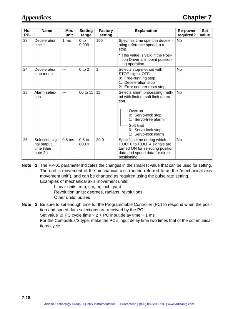
7-18
No.PP-
Setvalue
Re-powerrequired?
ExplanationFactorysetting
Settingrange
Min.unit
Name
23 Decelerationtime 1
1 ms 0 to9,999
100 Specifies time spent in deceler-ating reference speed to astop.
* This value is valid if the Posi-tion Driver is in point position-ing operation.
No
24 Decelerationstop mode
--- 0 to 2 1 Selects stop method withSTOP signal OFF.0: Free-running stop1: Deceleration stop2: Error counter reset stop
No
25 Alarm selec-tion
--- 00 to 11 11 Selects alarm processing meth-od with limit or soft limit detec-tion.
Overrun0: Servo-lock stop1: Servo-free alarm
Soft limit0: Servo-lock stop1: Servo-lock alarm
No
26 Selection sig-nal outputtime (Seenote 2.)
0.8 ms 0.8 to800.0
20.0 Specifies time during whichP.OUT0 to P.OUT4 signals areturned ON for selecting positiondata and speed data for directpositioning.
No
Note 1. The PP-01 parameter indicates the changes in the smallest value that can be used for setting.The unit is movement of the mechanical axis (herein referred to as the “mechanical axismovement unit”), and can be changed as required using the pulse rate setting.Examples of mechanical axis movement units:
Linear units: mm, cm, m, inch, yardRevolution units: degrees, radians, revolutionsOther units: pulses
Note 2. Be sure to set enough time for the Programmable Controller (PC) to respond when the posi-tion and speed data selections are received by the PC.Set value PC cycle time × 2 + PC input delay time + 1 msFor the CompoBus/S type, make the PC’s input delay time two times that of the communica-tions cycle.
Appendices Chapter 7
Artisan Technology Group - Quality Instrumentation ... Guaranteed | (888) 88-SOURCE | www.artisantg.com

7-19
PTP Data (Pd01 to Pd64 )
Explanation of SettingsNo.Pd
Name Minimumsetting
unit
Settingrange
Factorysetting
Description
H Point No. position data(leftmost digits)
(PP-01) (I/A)–3,999to3,999
(I) 0 Specifies point No. position data.A value between –39,999,999 and 39,999,999can be set. Leftmost digit is used to specify “A”(absolute) or “I” (incremental) value.
L Point No. position data(rightmost digits)
(PP-01) 0 to9,999
0
( ) ( )
F Point No. speed data
1% 1 to199
1 Specifies override value based on referencespeed.
A Point No. acceleration/de-celeration selec-tion
--- 00 to11
00 Selects acceleration/deceleration time for posi-tioning.
Acceleration0: Acceleration time 01: Acceleration time 1
Deceleration0 Deceleration time 01: Deceleration time 1
r Point No. operation modeselection
--- 0 to 2 0 0: Independent operation mode1: Automatic incremental mode2: Continuous operation mode
Note The position data (leftmost digits) display is as follows, according to whether the sign is plus orminus and whether the values are incremental or absolute.
Sign I (Incremental value designation) A (Absolute value designation)+
I + 1234 A + 1234
–I – 1234 A – 1234
Table for Entering SettingsNo.Pd-
Position data Speed data(F)
Acceleration/deceleration
Operationmode (r)Pd-
(I/A) Leftmost (H) Rightmost (L)(F) deceleration
selection (A)mode (r)
01
02
03
04
05
06
07
08
Appendices Chapter 7
Artisan Technology Group - Quality Instrumentation ... Guaranteed | (888) 88-SOURCE | www.artisantg.com

7-20
No.Pd-
Operationmode (r)
Acceleration/decelerationselection (A)
Speed data(F)
Position dataNo.Pd-
Operationmode (r)
Acceleration/decelerationselection (A)
Speed data(F)
Rightmost (L)Leftmost (H)(I/A)
09
10
11
12
13
14
15
16
17
18
19
20
21
22
23
24
25
26
27
29
29
30
31
32
33
34
35
36
37
38
39
40
41
42
43
44
45
46
47
48
49
50
Appendices Chapter 7
Artisan Technology Group - Quality Instrumentation ... Guaranteed | (888) 88-SOURCE | www.artisantg.com

7-21
No.Pd-
Operationmode (r)
Acceleration/decelerationselection (A)
Speed data(F)
Position dataNo.Pd-
Operationmode (r)
Acceleration/decelerationselection (A)
Speed data(F)
Rightmost (L)Leftmost (H)(I/A)
51
52
53
54
55
56
57
58
59
60
61
62
63
64
Adjustment Parameters (AJ2 to AJ9)No. Parameter name Min. unit Setting
rangeFactorysetting
Explanation Set val-ue
AJ2 Speed loop proportion-al gain
0.1x 0.0 to100.0
1.0 Gain for adjusting positionloop response
AJ3 Speed loop integralgain
0.1x 0.1 to 20.0 1.0 Speed loop integral gain
AJ4 Position loop gain 1 rad/s 1 to 200 30 Position loop gain
AJ7 Interrupt gain suppres-sion
1 0 to10,000
0 Speed loop proportionalgain suppression whenstopped
AJ8 Feed forward gain 0.1x 0.0 to 2.0 0.0 Feed forward gain
AJ9 Current reference filter 1 rad/s 400 to20,000
6,000 Cutoff frequency for cur-rent reference
Appendices Chapter 7
Artisan Technology Group - Quality Instrumentation ... Guaranteed | (888) 88-SOURCE | www.artisantg.com

R-1
Revision History
A manual revision code appears as a suffix to the catalog number on the front cover of the manual.
Cat. No. I524-E1-2
Revision code
The following table outlines the changes made to the manual during each revision. Page numbers refer to theprevious version.
Revision code Date Revised content
1 February 1998 Original production
2 April 1999 Major changes, including information on new Position Drivers, parameters, etc.,have been made.
Artisan Technology Group - Quality Instrumentation ... Guaranteed | (888) 88-SOURCE | www.artisantg.com

Cat. No. I524-E1-2 Note: Specifications subject to change without notice.
Authorized Distributor:
OMRON CorporationSystems Components Division14F Nissei Bldg.1-6-3, Osaki, Shinagawa-ku,Tokyo 141-0032 Japan Tel: (81)3-3779-9038/Fax: (81)3-3779-9041
Printed in Japan
Artisan Technology Group - Quality Instrumentation ... Guaranteed | (888) 88-SOURCE | www.artisantg.com

Artisan Technology Group is your source for quality new and certified-used/pre-owned equipment
• FAST SHIPPING AND DELIVERY
• TENS OF THOUSANDS OF IN-STOCK ITEMS
• EQUIPMENT DEMOS
• HUNDREDS OF MANUFACTURERS SUPPORTED
• LEASING/MONTHLY RENTALS
• ITAR CERTIFIED SECURE ASSET SOLUTIONS
SERVICE CENTER REPAIRSExperienced engineers and technicians on staff at our full-service, in-house repair center
WE BUY USED EQUIPMENTSell your excess, underutilized, and idle used equipment We also offer credit for buy-backs and trade-inswww.artisantg.com/WeBuyEquipment
REMOTE INSPECTIONRemotely inspect equipment before purchasing with our interactive website at www.instraview.com
LOOKING FOR MORE INFORMATION? Visit us on the web at www.artisantg.com for more information on price quotations, drivers, technical specifications, manuals, and documentation
Contact us: (888) 88-SOURCE | [email protected] | www.artisantg.com
SMViewInstra