artisan technology group is your source for quality … · 2016-01-04 · artisan technology group...
TRANSCRIPT

Artisan Technology Group is your source for quality new and certified-used/pre-owned equipment
• FAST SHIPPING AND DELIVERY
• TENS OF THOUSANDS OF IN-STOCK ITEMS
• EQUIPMENT DEMOS
• HUNDREDS OF MANUFACTURERS SUPPORTED
• LEASING/MONTHLY RENTALS
• ITAR CERTIFIED SECURE ASSET SOLUTIONS
SERVICE CENTER REPAIRSExperienced engineers and technicians on staff at our full-service, in-house repair center
WE BUY USED EQUIPMENTSell your excess, underutilized, and idle used equipment We also offer credit for buy-backs and trade-inswww.artisantg.com/WeBuyEquipment
REMOTE INSPECTIONRemotely inspect equipment before purchasing with our interactive website at www.instraview.com
LOOKING FOR MORE INFORMATION? Visit us on the web at www.artisantg.com for more information on price quotations, drivers, technical specifications, manuals, and documentation
Contact us: (888) 88-SOURCE | [email protected] | www.artisantg.com
SMViewInstra
Gen
eral
pu
rpo
se
Band
Rail
Tie-rod
Grommet
Connector
Terminal conduit
Grommet
Connector
Grommet
Terminal conduit
2-co
lor
ind
icat
ion
2-colo
r indic
ation
wit
h diag
nosti
c ou
tput
With
tim
erW
ater
res
ista
nt
2-co
lor
ind
icat
ion
Mag
netic
fiel
d re
sist
ance
Heat
resista
nt
Wide
range
detect
ion
1581
1582
1583
1584
1585
1586
1587
1588
1589
1590
D-H7A1/H7A2/H7B
D-G59/G5P/K59
D-H7C
D-G39/K39
D-G39A/K39A
D-F79/F7P/J79
D-F7NV/F7PV/F7BV
D-J79C
D-F59/F5P/J59
D-G39C/K39C
D-H7NF
D-G59F
D-F79F
D-F59F
D-H7BA
D-G5BA
D-M9PA/M9NA/M9BA
D-M9PAV/M9NAV/M9BAV
D-Y7BA
Grommet
Grommet
Grommet
Grommet
Grommet
Grommet
Grommet
Band
Rail
Tie-rod
Band
Rail
Tie-rod
Direct
Direct Grommet
1576
1577
1578
1579
1580
1575
D-M9NW/M9PW/M9BWD-M9NWV/M9PWV/M9BWV
D-Y7NW/Y7PW/Y7BW
D-Y7NWV/Y7PWV/Y7BWV
D-M5NW/M5PW/M5BW
D-H7NW/H7PW/H7BW
D-G59W/G5PW/K59W
D-F79W/F7PW/J79W
D-F7NWV/F7BWV
D-F59W/F5PW/J59W
1591
1592
1593
1594
1595
1596
1597
1598
GrommetDirect
Grommet
Grommet
Grommet
Band
Rail
Tie-rod
D-G5NT
D-F7NT
D-F5NT
D-M5NT/M5PT
D-P3DWSC/P3DWSE
D-P3DW
D-P4DWSC/P4DWSE
D-P4DW
Band
Rail
Tie-rod
Direct
Rail, Tie-rod,Direct
Grommet
Grommet
Grommet
Grommet
Grommet
1610
1611
1612
1613
1614
1615
1616
1617
Sensor section: RailAmplifier section: DIN rail
Band
Grommet
Grommet
D-F7NJ
D-G5NB
1603
1604
1605
1606
1607
1608
1599
1600
1601
1602
1618
1619
Trimm
er Au
to Sw
itch Rail
DirectGrommet D-F7K/Y7K 1620
Hygie
nic
Direct Grommet D-F6N/F6P/F6B 1609
So
lid S
tate
Au
to S
wit
ch
Rail Grommet
D-F7BA
D-F7BAV
D-F5BA
D-M9N/M9P/M9B
D-M9NV/M9PV/M9BV
D-F8N/F8P/F8B
D-F9G/F9H (Normally closed)
D-Y59A/Y59B/Y7P
D-Y69A/Y69B /Y7PV
D-Y7G/Y7H (Normally closed)
D-M5N/M5P/M5B
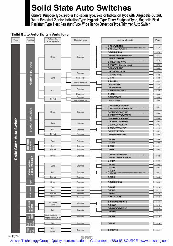
Solid State Auto SwitchesGeneral Purpose Type, 2-color Indication Type, 2-color Indication Type with Diagnostic Output, Water Resistant 2-color Indication Type, Hygienic Type, Timer Equipped Type, Magnetic Field Resistant Type, Heat Resistant Type, Wide Range Detection Type, Trimmer Auto Switch
FunctionType Electrical entry Auto switch model PageAuto switch
mounting style
Solid State Auto Switch Variations
1574A
Artisan Technology Group - Quality Instrumentation ... Guaranteed | (888) 88-SOURCE | www.artisantg.com
PrecautionsCaution
Fix the auto switch with the existing screw installed on the auto switch body. The auto switch may be damaged if a screw other than the one supplied is used.
Weight
Auto switch model
0.5 m (Nil)1 m (M)
3 m (L)
5 m (Z)
8
14
41
68
D-M9P(V) D-M9B(V)D-M9N(V)7
13
38
63
(g)
Lead wire length
Grommet
Note 1) Refer to page 1568 for solid state auto switch common specifications.Note 2) Refer to page 1568 for lead wire lengths.
DimensionsD-M9 D-M9V
2-wire load current is reduced (2.5 to 40 mA).
Flexibility is 1.5 times greater than the conventional model (SMC comparison).
Using flexible cable as standard spec.
(mm)
2 cores (Brown/Blue)
Auto switch model D-M9N D-M9P D-M9B
3 cores (Brown/Blue/Black)
Sheath
Insulator
Conductor
Outside diameter [mm]
Number of cores
Outside diameter [mm]
Effective area [mm2]
Strand diameter [mm]
Minimum bending radius [mm] (Reference values)
2.7 x 3.2 (ellipse)
ø0.9
0.15
ø0.05
20
Oilproof Heavy-duty Lead Wire Specifications
RoHS
Solid State Auto SwitchDirect Mounting StyleD-M9N(V)/D-M9P(V)/D-M9B(V)
Auto Switch Specifications
Auto switch model D-M9NVD-M9N D-M9B D-M9BV
2-wire
—
24 VDC relay, PLC
—
—
24 VDC (10 to 28 VDC)
2.5 to 40 mA
4 V or less
0.8 mA or less
D-M9PVD-M9P
Red LED illuminates when turned ON.
CE marking, RoHS
3-wire
IC circuit, Relay, PLC
5, 12, 24 VDC (4.5 to 28 V)
10 mA or less
40 mA or less
0.8 V or less at 10 mA (2 V or less at 40 mA)
100 µA or less at 24 VDC
In-line Perpendicular In-line Perpendicular In-line Perpendicular
NPN PNP
28 VDC or less —
D-M9, D-M9V (With indicator light)PLC: Programmable Logic Controller
Refer to SMC website for the details of the products conforming to the international standards.
M2.5 x 4 L
2.7
22
2.6
4
2.8
3.2
6
Slotted set screw
Indicator light
Most sensitive position
4
2.6
9.5
2.7
4.62
20
M2.5 x 4 L
2.8
83.2
4
Indicator lightSlotted set screw
6 Most sensitive position
Electrical entry direction
Wiring type
Output type
Applicable load
Power supply voltage
Current consumption
Load voltage
Load current
Internal voltage drop
Leakage current
Indicator light
Standard
1575
D-D-
Artisan Technology Group - Quality Instrumentation ... Guaranteed | (888) 88-SOURCE | www.artisantg.com

Grommet
Note 1) Refer to page 1568 for solid state auto switch common specifications.Note 2) Refer to page 1568 for lead wire lengths.
D-F8 (With indicator light)
Auto Switch Specifications
Auto switch model
Electrical entry direction
Wiring type
Output type
Applicable load
Power supply voltage
Current consumption
Load voltage
Load current
Internal voltage drop
Leakage current
Indicator light
Standard
D-F8N
Perpendicular
NPN
28 VDC or less
40 mA or less
D-F8B
Perpendicular
2-wire
—
24 VDC relay, PLC
—
—
24 VDC (10 to 28 VDC)
2.5 to 40 mA
4 V or less
0.8 mA or less at 24 VDC
D-F8P
Perpendicular
PNP
—
80 mA or less
0.8 V or less1.5 V or less(0.8 V or less
at 10 mA load current)
Red LED illuminates when turned ON.
CE marking, RoHS
100 µA or less at 24 VDC
3-wire
IC circuit, 24 VDC Relay, PLC
5, 12, 24 VDC (4.5 to 28 VDC)
10 mA or less
Refer to SMC website for the details of the products conforming to the international standards.
PLC: Programmable Logic Controller
Weight
Auto switch model
0.5 m (Nil)
3 m (L)
5 m (Z)
D-F8N D-F8P D-F8B7
32
52
(g)
Lead wire length
2 cores (Brown/Blue)
ø0.96
0.18
Auto switch model D-F8N D-F8P D-F8B
3 cores (Brown/Blue/Black)
ø0.91
0.15
Sheath
Insulator
Conductor
Outside diameter [mm]
Number of cores
Outside diameter [mm]
Effective area [mm2]
Strand diameter [mm]
Minimum bending radius [mm] (Reference values)
ø2.7
ø0.08
17
Oilproof Heavy-duty Lead Wire Specifications
RoHS
Solid State Auto SwitchDirect Mounting StyleD-F8N/D-F8P/D-F8B
PrecautionsCaution
Fix the auto switch with the existing screw installed on the auto switch body. The auto switch may be damaged if a screw other than the one supplied is used.
DimensionsD-F8N/D-F8P/D-F8B
M2.5 x 4 LSlotted set screw
Indicator light
Most sensitive position
10
4.62.
8
2
4.3
ø2.7
4
3.1
10.9
3
8
(mm)
1576Artisan Technology Group - Quality Instrumentation ... Guaranteed | (888) 88-SOURCE | www.artisantg.com

Weight (g)
Grommet
Note 1) Refer to page 1568 for solid state auto switch common specifications.Note 2) Refer to page 1568 for lead wire lengths.
Auto switch model
0.5 m (Nil)
3 m (L)
5 m (Z)
D-F9G D-F9H7
37
61
Lead wire length
PrecautionsCaution
Output signal turns on when no magnetic force is detected.
Fix the auto switch with the existing screw installed on the auto switch body. The auto switch may be damaged if a screw other than the one supplied is used.
Auto switch model D-F9G D-F9HSheath
Insulator
Conductor
Outside diameter [mm]
Number of cores
Outside diameter [mm]
Effective area [mm2]
Strand diameter [mm]
Minimum bending radius [mm] (Reference values)
ø2.7
3 cores (Brown/Blue/Black)
ø0.91
0.15
ø0.08
17
Oilproof Heavy-duty Lead Wire Specifications
RoHS
Normally Closed Solid State Auto SwitchDirect Mounting StyleD-F9G/D-F9H
Wiring type
Output type
Applicable load
Power supply voltage
Current consumption
Load voltage
Load current
Internal voltage drop
Leakage current
Indicator light
Standard
D-F9G, D-F9H (With indicator light)D-F9G
NPN
28 VDC or less
40 mA or less
1.5 V or less
(0.8 V or less at 10 mA load current)
D-F9H
PNP
—
80 mA or less
0.8 V or less
3-wire
IC circuit, Relay, PLC
5, 12, 24 VDC (4.5 to 28 VDC)
10 mA or less
100 µA or less at 24 VDC
Red LED illuminates when detecting nothing.
CE marking, RoHS
Auto Switch SpecificationsPLC: Programmable Logic Controller
Refer to SMC website for the details of the products conforming to the international standards.
Dimensions (mm)
M2.5 x 4 L
4
SMC D-F9H NC
2.8
22
2.6
6
ø2.
7
2
Slotted set screw
Indicator light
Most sensitive position
Auto switch model
1577
D-D-
Artisan Technology Group - Quality Instrumentation ... Guaranteed | (888) 88-SOURCE | www.artisantg.com
Weight
Auto switch model
0.5 m (Nil)
3 m (L)
5 m (Z)
D-Y59B D-Y69BD-Y69AD-Y59A D-Y7P(V)
9
50
83
10
53
87
(g)
Lead wire length
Note 1) Refer to page 1568 for solid state auto switch common specifications.Note 2) Refer to page 1568 for lead wire lengths.
Most sensitive position
Grommet
Using flexible cable as standard spec.
2 cores (Brown/Blue)
Auto switch model D-Y9A D-Y7P D-Y9B
3 cores (Brown/Blue/Black)
Sheath
Insulator
Conductor
Outside diameter [mm]
Number of cores
Outside diameter [mm]
Effective area [mm2]
Strand diameter [mm]
Minimum bending radius [mm] (Reference values)
ø3.4
ø1.0
0.15
ø0.05
21
Oilproof Flexible Heavy-duty Lead Wire Specifications
RoHS
Auto Switch Specifications
Electrical entry direction
Wiring type
Output type
Applicable load
Power supply voltage
Current consumption
Load voltage
Load current
Internal voltage drop
Leakage current
Indicator light
Standard
D-Y5, D-Y6, D-Y7P, D-Y7PV (With indicator light)D-Y59A
In-line
Red LED illuminates when turned ON.
CE marking, RoHS
D-Y69A
Perpendicular
D-Y69B
Perpendicular
D-Y7PV
Perpendicular
D-Y59B
In-line
D-Y7P
In-line
Refer to SMC website for the details of the products conforming to the international standards.
PLC: Programmable Logic Controller
1.5 V or less(0.8 V or less
at 10 mA load current)
100 µA or less at 24 VDC
2-wire
—
24 VDC relay, PLC
—
—
24 VDC (10 to 28 VDC)
2.5 to 40 mA
4 V or less
0.8 mA or less at 24 VDC
NPN
28 VDC or less
40 mA or less
PNP
—
80 mA or less
0.8 V or less
IC circuit, Relay, PLC
5, 12, 24 VDC (4.5 to 28 VDC)
10 mA or less
3-wire
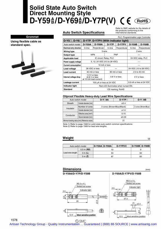
Dimensions (mm)
D-Y59A/D-Y7P/D-Y59B D-Y69A/D-Y7PV/D-Y69B
SM
C
SM
C
6.2
5
2.5
29
ø3.
4
12.5
27.3
6.2
5
12.5
8.5
2.5
ø3.4
Most sensitive position
M2.5 x 4 L
Slotted set screw
Slotted set screw
Indicator light
Indicator light
Most sensitive position
M2.5 x 4 L
Auto switch model
1578
AB
AB
Solid State Auto SwitchDirect Mounting StyleD-Y59 /D-Y69 /D-Y7P(V)
Artisan Technology Group - Quality Instrumentation ... Guaranteed | (888) 88-SOURCE | www.artisantg.com

Weight (g)
Grommet
Note 1) Refer to page 1568 for solid state auto switch common specifications.Note 2) Refer to page 1568 for lead wire lengths.
Auto switch model
0.5 m (Nil)
3 m (L)
5 m (Z)
D-Y7G D-Y7H10
53
87
Lead wire length
Most sensitive position
Auto switch model
D-Y7G, D-Y7H (With indicator light)D-Y7G
NPN
28 VDC or less
40 mA or less
1.5 V or less
(0.8 V or less at 10 mA load current)
D-Y7H
PNP
—
80 mA or less
0.8 V or less
3-wire
IC circuit, Relay, PLC
5, 12, 24 VDC (4.5 to 28 VDC)
10 mA or less
100 µA or less at 24 VDC
Red LED illuminates when detecting nothing.
CE marking, RoHS
Auto Switch SpecificationsPLC: Programmable Logic Controller
Refer to SMC website for the details of the products conforming to the international standards.
Output signal turns on when no magnetic force is detected.
Using flexible cable as standard spec.
Auto switch model D-Y7G D-Y7HSheath
Insulator
Conductor
Outside diameter [mm]
Number of cores
Outside diameter [mm]
Effective area [mm2]
Strand diameter [mm]
Minimum bending radius [mm] (Reference values)
ø3.4
3 cores (Brown/Blue/Black)
ø1.0
0.15
ø0.05
21
Oilproof Flexible Heavy-duty Lead Wire Specifications
RoHS
Normally Closed Solid State Auto SwitchDirect Mounting StyleD-Y7G/D-Y7H
SM
C
D-Y7G
NC6.2
5
2.5
29
ø3.
4
12.5
M2.5 x 4 LSlotted set screw
Indicator light
Dimensions (mm)
Wiring type
Output type
Applicable load
Power supply voltage
Current consumption
Load voltage
Load current
Internal voltage drop
Leakage current
Indicator light
Standard
1579
D-D-
Artisan Technology Group - Quality Instrumentation ... Guaranteed | (888) 88-SOURCE | www.artisantg.com

Indicator light
ø3 mounting hole
Most sensitive position
Weight (g)
Auto switch model
0.5 m (Nil)
3 m (L)
5 m (Z)
16
60
95
14
53
84
D-M5N D-M5P D-M5B
Lead wire length
Note 1) Refer to page 1568 for solid state auto switch common specifications.Note 2) Refer to page 1568 for lead wire lengths.
GrommetD-M5 (With indicator light)
D-M5N
NPN
28 VDC or less
40 mA or less
1.5 V or less(0.8 V or less
at 10 mA load current)
Auto switch model D-M5P
PNP
—
80 mA or less
0.8 V or less
Red LED illuminates when turned ON.
CE marking, RoHS
D-M5B
2-wire
—
24 VDC Relay, PLC
—
—
24 VDC (10 to 28 VDC)
5 to 40 mA
4 V or less
0.8 mA or less at 24 VDC
3-wire
IC circuit, Relay, PLC
5, 12, 24 VDC (4.5 to 28 VDC)
10 mA or less
100 µA or less at 24 VDC
Auto Switch SpecificationsPLC: Programmable Logic Controller
Refer to SMC website for the details of the products conforming to the international standards.
2 cores (Brown/Blue)
Auto switch model D-M5N D-M5P D-M5B
3 cores (Brown/Blue/Black)
Sheath
Insulator
Conductor
Outside diameter [mm]
Number of cores
Outside diameter [mm]
Effective area [mm2]
Strand diameter [mm]
Minimum bending radius [mm] (Reference values)
ø3.4
ø1.1
0.2
ø0.08
21
Oilproof Heavy-duty Lead Wire Specifications
RoHS
Solid State Auto SwitchDirect Mounting StyleD-M5N/D-M5P/D-M5B
Dimensions (mm)
Wiring type
Output type
Applicable load
Power supply voltage
Current consumption
Load voltage
Load current
Internal voltage drop
Leakage current
Indicator light
Standard
1580Artisan Technology Group - Quality Instrumentation ... Guaranteed | (888) 88-SOURCE | www.artisantg.com

Dimensions (mm)
Indicator light
ø3.5 mounting hole
Most sensitive position
Weight
Auto switch model
0.5 m (Nil)
3 m (L)
5 m (Z)
13
57
92
11
50
81
D-H7A1 D-H7A2 D-H7B
(g)
Grommet
Lead wire length
Note 1) Refer to page 1568 for solid state auto switch common specifications.Note 2) Refer to page 1568 for lead wire lengths.
2 cores (Brown/Blue)
Auto switch model D-H7A1 D-H7A2 D-H7B
3 cores (Brown/Blue/Black)
Sheath
Insulator
Conductor
Outside diameter [mm]
Number of cores
Outside diameter [mm]
Effective area [mm2]
Strand diameter [mm]
Minimum bending radius [mm] (Reference values)
ø3.4
ø1.1
0.2
ø0.08
21
Oilproof Heavy-duty Lead Wire Specifications
RoHS
Solid State Auto SwitchBand Mounting StyleD-H7A1/D-H7A2/D-H7B
D-H7 (With indicator light)Auto switch model
Wiring type
Output type
Applicable load
Power supply voltage
Current consumption
Load voltage
Load current
Internal voltage drop
Leakage current
Indicator light
Standard
D-H7A1
NPN
28 VDC or less
40 mA or less
1.5 V or less(0.8 V or less
at 10 mA load current)
D-H7A2
PNP
—
80 mA or less
0.8 V or less
Red LED illuminates when turned ON.
CE marking, RoHS
D-H7B
2-wire
—
24 VDC Relay, PLC
—
—
24 VDC (10 to 28 VDC)
5 to 40 mA
4 V or less
0.8 mA or less at 24 VDC
3-wire
IC circuit, Relay, PLC
5, 12, 24 VDC (4.5 to 28 VDC)
10 mA or less
100 µA or less at 24 VDC
Auto Switch SpecificationsPLC: Programmable Logic Controller
Refer to SMC website for the details of the products conforming to the international standards.
1581
D-D-
Artisan Technology Group - Quality Instrumentation ... Guaranteed | (888) 88-SOURCE | www.artisantg.com

Weight
Auto switch model
0.5 m (Nil)
3 m (L)
5 m (Z)
20
78
124
18
68
108
D-G59 D-G5P D-K59
(g)
Grommet
Lead wire length
Note 1) Refer to page 1568 for solid state auto switch common specifications.Note 2) Refer to page 1568 for lead wire lengths.
2 cores (Brown/Blue)
Auto switch model D-G59 D-G5P D-K59
3 cores (Brown/Blue/Black)
Sheath
Insulator
Conductor
Outside diameter [mm]
Number of cores
Outside diameter [mm]
Effective area [mm2]
Strand diameter [mm]
Minimum bending radius [mm] (Reference values)
ø4
ø1.22
0.3
ø0.08
24
Oilproof Heavy-duty Lead Wire Specifications
RoHS
Solid State Auto SwitchBand Mounting StyleD-G59/D-G5P/D-K59
D-G5, D-K59 (With indicator light)Auto switch model
Wiring type
Output type
Applicable load
Power supply voltage
Current consumption
Load voltage
Load current
Internal voltage drop
Leakage current
Indicator light
Standard
D-G59
NPN
28 VDC or less
40 mA or less
1.5 V or less(0.8 V or less
at 10 mA load current)
D-G5P
PNP
—
80 mA or less
0.8 V or less
Red LED illuminates when turned ON.
CE marking, RoHS
D-K59
2-wire
—
24 VDC Relay, PLC
—
—
24 VDC (10 to 28 VDC)
5 to 40 mA
4 V or less
0.8 mA or less at 24 VDC
3-wire
IC circuit, Relay, PLC
5, 12, 24 VDC (4.5 to 28 VDC)
10 mA or less
100 µA or less at 24 VDC
Auto Switch SpecificationsPLC: Programmable Logic Controller
Refer to SMC website for the details of the products conforming to the international standards.
Dimensions (mm)
Indicator light
ø4.5 mounting hole
Most sensitive position
1582Artisan Technology Group - Quality Instrumentation ... Guaranteed | (888) 88-SOURCE | www.artisantg.com

Weight
Auto switch model
0.5 m (Nil)
3 m (L)
5 m (Z)
15
54
85
D-H7C
(g)
Connector
Lead wire length
1. Confirm that the connector is appropriately tightened. If tightened insufficiently, the waterproof performance will deteriorate.
2. Refer to page 1653 for the details.
PrecautionsCaution
Lead wires with a connector indication
Model
D-LC05
D-LC30
D-LC50
Lead wire length
0.5 m
3 m
5 m
Part No. of Lead Wires with Connectors(Applicable only for connector type)
RoHS
D-H7C (With indicator light)Auto switch model
Wiring type
Output type
Applicable load
Power supply voltage
Current consumption
Load voltage
Load current
Internal voltage drop
Leakage current
Indicator light
Standard
D-H7C
2-wire
—
24 VDC Relay, PLC
—
—
24 VDC (10 to 28 VDC)
5 to 40 mA
4 V or less
0.8 mA or less at 24 VDC
Red LED illuminates when turned ON.
CE marking, RoHS
Auto Switch SpecificationsPLC: Programmable Logic Controller
Refer to SMC website for the details of the products conforming to the international standards.
Dimensions (mm)
Indicator light
ø3.5 mounting hole
Most sensitive position
Note 1) Refer to page 1568 for solid state auto switch common specifications.Note 2) Refer to page 1568 for lead wire lengths.Note 3) Lead wires with a connector may be shipped with switches.
1583
Solid State Auto SwitchBand Mounting StyleD-H7C
D-D-
Artisan Technology Group - Quality Instrumentation ... Guaranteed | (888) 88-SOURCE | www.artisantg.com

Terminal conduit
RoHS
Solid State Auto SwitchBand Mounting StyleD-G39/D-K39
1. Use cable whose O.D. is within the size in the figure to maintain water resistant performance.
2. After wiring, confirm that tightening gland and all screws are tightened.
PrecautionsCaution
D-G39, D-K39 (With indicator light)Auto switch model D-G39
3-wire
NPN
IC circuit, Relay, PLC
5, 12, 24 VDC (4.5 to 28 VDC)
10 mA or less
28 VDC or less
40 mA or less
1.5 V or less(0.8 V or less
at 10 mA of load current)
100 µA or less at 24 VDC
D-K39
2-wire
—
24 VDC Relay, PLC
—
—
24 VDC (10 to 28 VDC)
5 to 40 mA
4 V or less
0.8 mA or less at 24 VDC
Note) Refer to page 1568 for solid state auto switch common specifications.
Red LED illuminates when turned ON.
CE marking, RoHS
Auto Switch SpecificationsPLC: Programmable Logic Controller
Refer to SMC website for the details of the products conforming to the international standards.
Auto switch model
None 116
D-G39 D-K39
Weight (g)
Lead wire
Dimensions (mm)
(Applicable cable O.D. ø6.8 to ø9.6)
Tightening gland
G (PF) 1/2
Indicator light Most sensitive position
Wiring type
Output type
Applicable load
Power supply voltage
Current consumption
Load voltage
Load current
Internal voltage drop
Leakage current
Indicator light
Standard
1584Artisan Technology Group - Quality Instrumentation ... Guaranteed | (888) 88-SOURCE | www.artisantg.com

Terminal conduit
RoHS
Solid State Auto SwitchBand Mounting StyleD-G39A/D-K39A
1. Use cable whose O.D. is within the size in the figure to maintain water resistant performance.
2. After wiring, confirm that tightening gland and all screws are tightened.
PrecautionsCaution
D-G39A, D-K39A (With indicator light)Auto switch model D-G39A
3-wire
NPN
IC circuit, Relay, PLC
5, 12, 24 VDC (4.5 to 28 VDC)
10 mA or less
28 VDC or less
40 mA or less
1.5 V or less(0.8 V or less
at 10 mA of load current)
100 µA or less at 24 VDC
D-K39A
2-wire
—
24 VDC Relay, PLC
—
—
24 VDC (10 to 28 VDC)
5 to 40 mA
4 V or less
0.8 mA or less at 24 VDC
Note) Refer to page 1568 for solid state auto switch common specifications.
Red LED illuminates when turned ON.
CE marking, RoHS
Auto Switch SpecificationsPLC: Programmable Logic Controller
Refer to SMC website for the details of the products conforming to the international standards.
Dimensions (mm)
Auto switch model
None 110
D-G39A D-K39ALead wire
Weight (g)
G (PF) 1/2
Tightening gland
Indicator light Most sensitive position
(Applicable cable O.D. ø6.8 to ø9.6)
Wiring type
Output type
Applicable load
Power supply voltage
Current consumption
Load voltage
Load current
Internal voltage drop
Leakage current
Indicator light
Standard
1585
D-D-
Artisan Technology Group - Quality Instrumentation ... Guaranteed | (888) 88-SOURCE | www.artisantg.com

Weight
Auto switch model
0.5 m (Nil)
3 m (L)
5 m (Z)
D-F79 D-F7P D-J79
(g)
Grommet
Lead wire length
Note 1) Refer to page 1568 for solid state auto switch common specifications.Note 2) Refer to page 1568 for lead wire lengths.
11
50
81
13
57
92
2 cores (Brown/Blue)
Auto switch model D-F79 D-F7P D-J79
3 cores (Brown/Blue/Black)
Sheath
Insulator
Conductor
Outside diameter [mm]
Number of cores
Outside diameter [mm]
Effective area [mm2]
Strand diameter [mm]
Minimum bending radius [mm] (Reference values)
ø3.4
ø1.1
0.2
ø0.08
21
Oilproof Heavy-duty Lead Wire Specifications
RoHS
Solid State Auto SwitchRail Mounting StyleD-F79/D-F7P/D-J79
Auto Switch Specifications
D-F7, D-J79 (With indicator light)PLC: Programmable Logic Controller
Auto switch model
Wiring type
Output type
Applicable load
Power supply voltage
Current consumption
Load voltage
Load current
Internal voltage drop
Leakage current
Indicator light
Standard
D-F79
NPN
28 VDC or less
40 mA or less
1.5 V or less(0.8 V or less
at 10 mA load current)
D-F7P
PNP
—
80 mA or less
0.8 V or less
Red LED illuminates when turned ON.
CE marking, RoHS
3-wire
IC circuit, Relay, PLC
5, 12, 24 VDC (4.5 to 28 VDC)
10 mA or less
100 µA or less at 24 VDC
D-J79
2-wire
—
24 VDC Relay, PLC
—
—
24 VDC (10 to 28 VDC)
5 to 40 mA
4 V or less
0.8 mA or less at 24 VDC
Refer to SMC website for the details of the products conforming to the international standards.
Dimensions (mm)
Indicator light
Most sensitive position
ø3.2 mounting hole
1586Artisan Technology Group - Quality Instrumentation ... Guaranteed | (888) 88-SOURCE | www.artisantg.com

Weight
Auto switch model
0.5 m (Nil)
3 m (L)
5 m (Z)
13
57
92
11
50
81
D-F7NV D-F7PV D-F7BV
(g)
GrommetElectrical entry: Perpendicular
Lead wire length
Note 1) Refer to page 1568 for solid state auto switch common specifications.Note 2) Refer to page 1568 for lead wire lengths.
2 cores (Brown/Blue)
Auto switch model D-F7NV D-F7PV D-F7BV
3 cores (Brown/Blue/Black)
Sheath
Insulator
Conductor
Outside diameter [mm]
Number of cores
Outside diameter [mm]
Effective area [mm2]
Strand diameter [mm]
Minimum bending radius [mm] (Reference values)
ø3.4
ø1.1
0.2
ø0.08
21
Oilproof Heavy-duty Lead Wire Specifications
RoHS
D-F7V (With indicator light)Auto switch model D-F7NV
NPN
28 VDC or less
40 mA or less
1.5 V or less(0.8 V or less
at 10 mA load current)
D-F7PV
PNP
—
80 mA or less
0.8 V or less
Red LED illuminates when turned ON.
CE marking, RoHS
D-F7BV
2-wire
—
24 VDC Relay, PLC
—
—
24 VDC (10 to 28 VDC)
5 to 40 mA
4 V or less
0.8 mA or less at 24 VDC
3-wire
IC circuit, Relay, PLC
5, 12, 24 VDC (4.5 to 28 VDC)
10 mA or less
100 µA or less at 24 VDC
Refer to SMC website for the details of the products conforming to the international standards.Auto Switch Specifications
PLC: Programmable Logic Controller
Dimensions (mm)
Indicator light
Most sensitive position
ø3.2 mounting hole
Wiring type
Output type
Applicable load
Power supply voltage
Current consumption
Load voltage
Load current
Internal voltage drop
Leakage current
Indicator light
Standard
1587
Solid State Auto SwitchRail Mounting StyleD-F7NV/D-F7PV/D-F7BV
D-D-
Artisan Technology Group - Quality Instrumentation ... Guaranteed | (888) 88-SOURCE | www.artisantg.com
Weight
Auto switch model
0.5 m (Nil)
3 m (L)
5 m (Z)
13
52
83
D-J79C
(g)
Connector
Lead wire lengthLead wires with a connector indication
Model
D-LC05
D-LC30
D-LC50
Lead wire length
0.5 m
3 m
5 m
Part No. of Lead Wires with Connectors(Applicable only for connector type)
RoHS
Solid State Auto SwitchRail Mounting StyleD-J79C
1. Confirm that the connector is appropriately tightened. If tightened insufficiently, the waterproof performance will deteriorate.
2. Refer to page 1653 for the details.
PrecautionsCaution
D-J79C (With indicator light)Auto switch model
Wiring type
Output type
Applicable load
Power supply voltage
Current consumption
Load voltage
Load current
Internal voltage drop
Leakage current
Indicator light
Standard
D-J79C
2-wire
—
24 VDC Relay, PLC
—
—
24 VDC (10 to 28 VDC)
5 to 40 mA
4 V or less
0.8 mA or less at 24 VDC
Red LED illuminates when turned ON.
CE marking, RoHS
Refer to SMC website for the details of the products conforming to the international standards.Auto Switch Specifications
PLC: Programmable Logic Controller
Note 1) Refer to page 1568 for solid state auto switch common specifications.Note 2) Refer to page 1568 for lead wire lengths.Note 3) Lead wires with a connector may be shipped with auto switches.
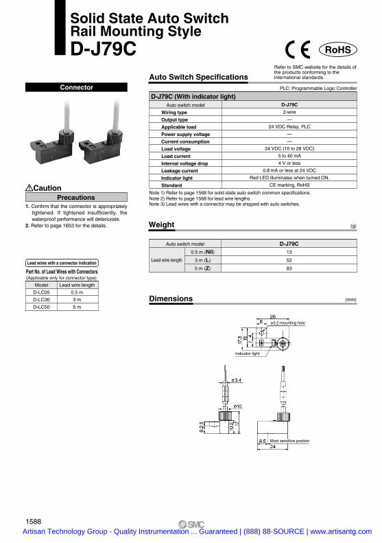
Dimensions (mm)
ø3.2 mounting hole
Indicator light
Most sensitive position
1588Artisan Technology Group - Quality Instrumentation ... Guaranteed | (888) 88-SOURCE | www.artisantg.com

Dimensions
Auto switch model
0.5 m (Nil)
3 m (L)
5 m (Z)
23
81
127
D-F59 D-F5P D-J5921
71
111
(mm)
Lead wire length
Grommet
Note 1) Refer to page 1568 for solid state auto switch common specifications.Note 2) Refer to page 1568 for lead wire lengths.
D-F59/D-F5P/D-J59
2 cores (Brown/Blue)
Auto switch model D-F59 D-F5P D-J59
3 cores (Brown/Blue/Black)
Sheath
Insulator
Conductor
Outside diameter [mm]
Number of cores
Outside diameter [mm]
Effective area [mm2]
Strand diameter [mm]
Minimum bending radius [mm] (Reference values)
ø4
ø1.22
0.3
ø0.08
24
Oilproof Heavy-duty Lead Wire Specifications
RoHS
Solid State Auto SwitchTie-rod Mounting StyleD-F59/D-F5P/D-J59
D-F5, D-J59 (With indicator light)Auto switch model
Wiring type
Output type
Applicable load
Power supply voltage
Current consumption
Load voltage
Load current
Internal voltage drop
Leakage current
Indicator light
Standard
D-F59
NPN
28 VDC or less
40 mA or less
1.5 V or less(0.8 V or less at
10 mA load current)
D-F5P
PNP
—
80 mA or less
0.8 V or less
D-J59
—
24 VDC Relay, PLC
—
—
24 VDC (10 to 28 VDC)
5 to 40 mA
4 V or less
0.8 mA or less at 24 VDC
3-wire
IC circuit, Relay, PLC
5, 12, 24 VDC (4.5 to 28 VDC)
10 mA or less
100 µA or less at 24 VDC
Red LED illuminates when turned ON.
CE marking, RoHS
2-wire
Refer to SMC website for the details of the products conforming to the international standards.Auto Switch Specifications
PLC: Programmable Logic Controller
Weight (g)
Mounting hole
Indicator light
Most sensitive position
1589
D-D-
A
Artisan Technology Group - Quality Instrumentation ... Guaranteed | (888) 88-SOURCE | www.artisantg.com

Terminal conduit
RoHS
Solid State Auto SwitchTie-rod Mounting StyleD-G39C/D-K39C
D-G39C, D-K39C (With indicator light)Auto switch model
Wiring type
Output type
Applicable load
Power voltage
Current consumption
Load voltage
Load current
Internal voltage drop
Current leakage
Indicator light
Standard
D-G39C3-wire
NPN
IC circuit, Relay, PLC
5, 12, 24 VDC (4.5 to 28 VDC)
10 mA or less
28 VDC or less
40 mA or less1.5 V or less(0.8 V or less
at 10 mA of load current)
100 µA or less at 24 VDC
D-K39C2-wire
—
24 VDC Relay, PLC
—
—
24 VDC (10 to 28 VDC)
5 to 40 mA
4 V or less
0.8 mA or less at 24 VDC
Note) Refer to page 1568 for solid state auto switch common specifications.
Red LED illuminates when turned ON.
CE marking, RoHS
Auto Switch SpecificationsPLC: Programmable Logic Controller
Refer to SMC website for the details of the products conforming to the international standards.
Auto switch model Applicable bore size (mm) Weight
40
50
63
80
100
162
166
184
210
232
D-G39C-4, K39C-4
D-G39C-5, K39C-5
D-G39C-6, K39C-6
D-G39C-8, K39C-8
D-G39C-10, K39C-10
Weight (g)
Dimensions (mm)
Dimensions
Auto switch model
D-G39C-4, D-K39C-4D-G39C-5, D-K39C-5D-G39C-6, D-K39C-6D-G39C-8, D-K39C-8D-G39C-10, D-K39C-10
C
4452647892
HW
697791
107121
H
5758
60.56467
H´
49.550.552
53.556.5
T
7.58.5
10.512.515.5
T´
6.56.57.59.59.5
Applicable boresize (mm)
40506380
100
Z
M5 x 0.8 x 16
M5 x 0.8 x 20
M5 x 0.8 x 25
2 x M5 x 0.8 x 12Hexagon socket head cap bolt
Tightening gland
G (PF) 1/2
4 x Z
(Applicable cable O.D. ø6.8 to ø9.6)
Indicator light
Most sensitive position
Hexagon socket head cap bolt
1. Use cable whose O.D. is within the size in the figure to maintain water resistant performance.
2. After wiring, confirm that tightening gland and all screws are tightened.
PrecautionsCaution
1590Artisan Technology Group - Quality Instrumentation ... Guaranteed | (888) 88-SOURCE | www.artisantg.com

Weight (g)
(mm)Dimensions
Auto switch model
0.5 m (Nil)1 m (M)
3 m (L)
5 m (Z)
D-M9NW(V)8
14
41
68
D-M9PW(V) D-M9BW(V)7
13
38
63
Lead wire length
Grommet
Note 1) Refer to page 1568 for solid state auto switch common specifications.Note 2) Refer to page 1568 for lead wire lengths.
2-wire load current is reduced (2.5 to 40 mA).
Flexibility is 1.5 times greater than the conventional model (SMC comparison).
Using flexible cable as standard spec.
The proper operating range can be determined by the color of the light. (Red → Green ← Red)
D-M9W D-M9WV
RoHS
2 cores (Brown/Blue)
Auto switch model D-M9NW D-M9PW D-M9BW
3 cores (Brown/Blue/Black)
Sheath
Insulator
Conductor
Outside diameter [mm]
Number of cores
Outside diameter [mm]
Effective area [mm2]
Strand diameter [mm]
Minimum bending radius [mm] (Reference values)
2.7 x 3.2 (ellipse)
ø0.9
0.15
ø0.05
20
Oilproof Flexible Heavy-duty Lead Wire Specifications
2-Color Indication Type Solid State Auto SwitchDirect Mounting StyleD-M9NW(V)/D-M9PW(V)/D-M9BW(V)
PrecautionsCaution
Fix the auto switch with the existing screw installed on the auto switch body. The auto switch may be damaged if a screw other than the one supplied is used.
Auto switch model
Electrical entry direction
Wiring type
Output type
Applicable load
Power supply voltage
Current consumption
Load voltage
Load current
Internal voltage drop
Leakage current
Indicator light
Standard
D-M9NWVD-M9NW D-M9BW D-M9BWV
2-wire
—
24 VDC relay, PLC
—
—
24 VDC (10 to 28 VDC)
2.5 to 40 mA
4 V or less
0.8 mA or less
D-M9PWVD-M9PW
Operating range .......... Red LED illuminates.Proper operating range .......... Green LED illuminates.
3-wire
IC circuit, Relay, PLC
5, 12, 24 VDC (4.5 to 28 V)
10 mA or less
40 mA or less
0.8 V or less at 10 mA (2 V or less at 40 mA)
100 µA or less at 24 VDC
CE marking, RoHS
In-line Perpendicular In-line Perpendicular In-line Perpendicular
NPN PNP
28 VDC or less —
D-M9W, D-M9WV (With indicator light)
Auto Switch SpecificationsRefer to SMC website for the details of the products conforming to the international standards.
PLC: Programmable Logic Controller
M2.5 x 4 LSlotted set screw
Indicator light
2.7
22
2.6
4
2.8
3.2
6 Most sensitive position 4
2.6
9.5
M2.5 x 4 L
Indicator light
Slotted set screw
2.8
4.6
4
20
28
3.2
6 Most sensitive position
2.7
1591
D-D-
Artisan Technology Group - Quality Instrumentation ... Guaranteed | (888) 88-SOURCE | www.artisantg.com

Dimensions
Grommet
Note 1) Refer to page 1568 for solid state auto switch common specifications.Note 2) Refer to page 1568 for lead wire lengths.
Weight
Auto switch model
0.5 m (Nil)
3 m (L)
5 m (Z)
D-Y7NW(V) D-Y7PW(V) D-Y7BW(V)
11
54
88
(g)
(mm)
Lead wire length
D-Y7W D-Y7WV
2 cores (Brown/Blue)
Auto switch model D-Y7NW D-Y7PW D-Y7BW
3 cores (Brown/Blue/Black)
Sheath
Insulator
Conductor
Outside diameter [mm]
Number of cores
Outside diameter [mm]
Effective area [mm2]
Strand diameter [mm]
Minimum bending radius [mm] (Reference values)
ø3.4
ø1.0
0.15
ø0.05
21
Oilproof Flexible Heavy-duty Lead Wire Specifications
RoHS
The proper operating range can be determined by the color of the light.(Red → Green ← Red)
Using flexible cable as standard spec.
D-Y7W, D-Y7WV (With indicator light)Auto switch model
Electrical entry direction
Wiring type
Output type
Applicable load
Power supply voltage
Current consumption
Load voltage
Load current
Internal voltage drop
Leakage current
Indicator light
Standard
D-Y7NW
In-line
D-Y7NWV
Perpendicular
D-Y7BWV
Perpendicular
D-Y7PWV
Perpendicular
D-Y7BWD-Y7PW
In-line
1.5 V or less(0.8 V or less
at 10 mA load current)
CE marking, RoHS
Auto Switch SpecificationsRefer to SMC website for the details of the products conforming to the international standards.
PLC: Programmable Logic Controller
Operating range .......... Red LED illuminates.Proper operating range .......... Green LED illuminates.
2-wire
—
24 VDC relay, PLC
—
—
24 VDC (10 to 28 VDC)
2.5 to 40 mA
4 V or less
0.8 mA or less at 24 VDC
In-line
PNP
—
80 mA or less
0.8 V or less
NPN
28 VDC or less
40 mA or less
5, 12, 24 VDC (4.5 to 28 VDC)
100 µA or less at 24 VDC
10 mA or less
IC circuit, Relay, PLC
3-wire
M2.5 x 4 LSlotted set screw
Indicator light
Most sensitive position
SM
C
6.2
5
2.5
29
ø3.
4
12.5
M2.5 x 4 LSlotted set screw
Indicator light
SM
C
27.3
6.2
5
12.5
8.5
2.5
ø3.4
Most sensitive position
1592
2-Color Indication Type Solid State Auto SwitchDirect Mounting StyleD-Y7NW(V)/D-Y7PW(V)/D-Y7BW(V)
Artisan Technology Group - Quality Instrumentation ... Guaranteed | (888) 88-SOURCE | www.artisantg.com

Grommet
The proper operating range can be determined by the color of the light.(Red → Green ← Red)
Note 1) Refer to page 1568 for solid state auto switch common specifications.Note 2) Refer to page 1568 for lead wire lengths.
Weight
Auto switch model
0.5 m (Nil)
3 m (L)
5 m (Z)
16
60
95
14
53
84
D-M5NW D-M5PW D-M5BW
(g)
Lead wire length
2 cores (Brown/Blue)
Auto switch model D-M5NW D-M5PW D-M5BW
3 cores (Brown/Blue/Black)
Sheath
Insulator
Conductor
Outside diameter [mm]
Number of cores
Outside diameter [mm]
Effective area [mm2]
Strand diameter [mm]
Minimum bending radius [mm] (Reference values)
ø3.4
ø1.1
0.2
ø0.08
21
Oilproof Heavy-duty Lead Wire Specifications
RoHS
D-M5W (With indicator light)Auto switch model
Wiring type
Output type
Applicable load
Power supply voltage
Current consumption
Load voltage
Load current
Internal voltage drop
Leakage current
Indicator light
Standard
D-M5NW
3-wire
NPN
IC circuit, Relay, PLC
5, 12, 24 VDC (4.5 to 28 VDC)
10 mA or less
28 VDC or less
40 mA or less
1.5 V or less(0.8 V or less
at 10 mA load current)
100 µA or less at 24 VDC
D-M5BW
2-wire
—
24 VDC Relay, PLC
—
—
24 VDC (10 to 28 VDC)
5 to 40 mA
4 V or less
0.8 mA or less at 24 VDC
D-M5PW
PNP
—
80 mA or less
0.8 V or less
CE marking, RoHS
Auto Switch SpecificationsPLC: Programmable Logic Controller
Refer to SMC website for the details of the products conforming to the international standards.
Operating range .......... Red LED illuminates.Proper operating range .......... Green LED illuminates.
Dimensions (mm)
Indicator light
ø3 mounting hole
Most sensitive position
1593
2-Color Indication Type Solid State Auto SwitchDirect Mounting StyleD-M5NW/D-M5PW/D-M5BW
D-D-
Artisan Technology Group - Quality Instrumentation ... Guaranteed | (888) 88-SOURCE | www.artisantg.com

Weight (g)
Auto switch model
0.5 m (Nil)
3 m (L)
5 m (Z)
13
57
92
11
50
81
D-H7NW D-H7PW D-H7BW
Lead wire length
Grommet
The proper operating range can be determined by the color of the light.(Red → Green ← Red)
Note 1) Refer to page 1568 for solid state auto switch common specifications.Note 2) Refer to page 1568 for lead wire lengths.
2 cores (Brown/Blue)
Auto switch model D-H7NW D-H7PW D-H7BW
3 cores (Brown/Blue/Black)
Sheath
Insulator
Conductor
Outside diameter [mm]
Number of cores
Outside diameter [mm]
Effective area [mm2]
Strand diameter [mm]
Minimum bending radius [mm] (Reference values)
ø3.4
ø1.1
0.2
ø0.08
21
Oilproof Heavy-duty Lead Wire Specifications
RoHS
2-Color Indication Type Solid State Auto SwitchBand Mounting StyleD-H7NW/D-H7PW/D-H7BW
D-H7W (With indicator light)Auto switch model
Wiring type
Output type
Applicable load
Power supply voltage
Current consumption
Load voltage
Load current
Internal voltage drop
Leakage current
Indicator light
Standard
D-H7NW
3-wire
NPN
IC circuit, Relay, PLC
5, 12, 24 VDC (4.5 to 28 VDC)
10 mA or less
28 VDC or less
40 mA or less
1.5 V or less(0.8 V or less
at 10 mA load current)
100 µA or less at 24 VDC
D-H7BW
2-wire
—
24 VDC relay, PLC
—
—
24 VDC (10 to 28 VDC)
5 to 40 mA
4 V or less
0.8 mA or less at 24 VDC
D-H7PW
PNP
—
80 mA or less
0.8 V or less
CE marking, RoHS
Auto Switch SpecificationsPLC: Programmable Logic Controller
Refer to SMC website for the details of the products conforming to the international standards.
Operating range .......... Red LED illuminates.Proper operating range .......... Green LED illuminates.
Dimensions (mm)
4.6
29
9
4.3
10.5Most sensitive position
6.58
811.5
Indicator light
ø3.
4
ø3.5 mounting hole
1594Artisan Technology Group - Quality Instrumentation ... Guaranteed | (888) 88-SOURCE | www.artisantg.com
Weight (g)
Auto switch model
0.5 m (Nil)
3 m (L)
5 m (Z)
20
78
124
18
68
108
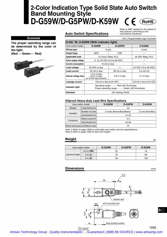
D-G59W D-G5PW D-K59W
Lead wire length
Grommet
The proper operating range can be determined by the color of the light.(Red → Green ← Red)
Note 1) Refer to page 1568 for solid state auto switch common specifications.Note 2) Refer to page 1568 for lead wire lengths.
2 cores (Brown/Blue)
Auto switch model D-G59W D-G5PW D-K59W
3 cores (Brown/Blue/Black)
Sheath
Insulator
Conductor
Outside diameter [mm]
Number of cores
Outside diameter [mm]
Effective area [mm2]
Strand diameter [mm]
Minimum bending radius [mm] (Reference values)
ø4
ø1.22
0.3
ø0.08
24
Oilproof Heavy-duty Lead Wire Specifications
RoHS
2-Color Indication Type Solid State Auto SwitchBand Mounting StyleD-G59W/D-G5PW/D-K59W
D-G5W, D-K59W (With indicator light)Auto switch model
Wiring type
Output type
Applicable load
Power supply voltage
Current consumption
Load voltage
Load current
Internal voltage drop
Leakage current
Indicator light
Standard
D-G59W
3-wire
NPN
IC circuit, Relay, PLC
5, 12, 24 VDC (4.5 to 28 VDC)
10 mA or less
28 VDC or less
40 mA or less
100 µA or less at 24 VDC
D-K59W
2-wire
—
24 VDC Relay, PLC
—
—
24 VDC (10 to 28 VDC)
5 to 40 mA
4 V or less
0.8 mA or less at 24 VDC
D-G5PW
PNP
—
80 mA or less
0.8 V or less1.5 V or less(0.8 V or less
at 10 mA load current)
CE marking, RoHS
Auto Switch SpecificationsPLC: Programmable Logic Controller
Refer to SMC website for the details of the products conforming to the international standards.
Operating range .......... Red LED illuminates.Proper operating range .......... Green LED illuminates.
Dimensions (mm)
Indicator light
ø4.5 mounting hole
Most sensitive position
1595
D-D-
Artisan Technology Group - Quality Instrumentation ... Guaranteed | (888) 88-SOURCE | www.artisantg.com

Weight (g)
Auto switch model
0.5 m (Nil)
3 m (L)
5 m (Z)
13
57
92
11
50
81
D-F79W D-F7PW D-J79W
Lead wire length
Grommet
Note 1) Refer to page 1568 for solid state auto switch common specifications.Note 2) Refer to page 1568 for lead wire lengths.
2 cores (Brown/Blue)
Auto switch model D-F79W D-F7PW D-J79W
3 cores (Brown/Blue/Black)
Sheath
Insulator
Conductor
Outside diameter [mm]
Number of cores
Outside diameter [mm]
Effective area [mm2]
Strand diameter [mm]
Minimum bending radius [mm] (Reference values)
ø3.4
ø1.1
0.2
ø0.08
21
Oilproof Heavy-duty Lead Wire Specifications
RoHS
2-Color Indication Type Solid State Auto SwitchRail Mounting StyleD-F79W/D-F7PW/D-J79W
The proper operating range can be determined by the color of the light.(Red → Green ← Red)
D-F7W, D-J79W (With indicator light)Auto switch model
Wiring type
Output type
Applicable load
Power supply voltage
Current consumption
Load voltage
Load current
Internal voltage drop
Leakage current
Indicator light
Standard
D-F79W
3-wire
NPN
IC circuit, Relay, PLC
5, 12, 24 VDC (4.5 to 28 VDC)
10 mA or less
28 VDC or less
40 mA or less
100 µA or less at 24 VDC
D-J79W
2-wire
—
24 VDC Relay, PLC
—
—
24 VDC (10 to 28 VDC)
5 to 40 mA
4 V or less
0.8 mA or less at 24 VDC
D-F7PW
PNP
—
80 mA or less
0.8 V or less1.5 V or less(0.8 V or less
at 10 mA load current)
CE marking, RoHS
Auto Switch SpecificationsRefer to SMC website for the details of the products conforming to the international standards.
PLC: Programmable Logic Controller
Operating range .......... Red LED illuminates.Proper operating range .......... Green LED illuminates.
Indicator light
ø3.2 mounting hole
8
23
4.6
15
7
Most sensitive position8.5
11
6.2
3.2
ø3.
4
Dimensions (mm)
1596Artisan Technology Group - Quality Instrumentation ... Guaranteed | (888) 88-SOURCE | www.artisantg.com
Weight (g)
Auto switch model
0.5 m (Nil)
3 m (L)
5 m (Z)
13
57
92
11
50
81
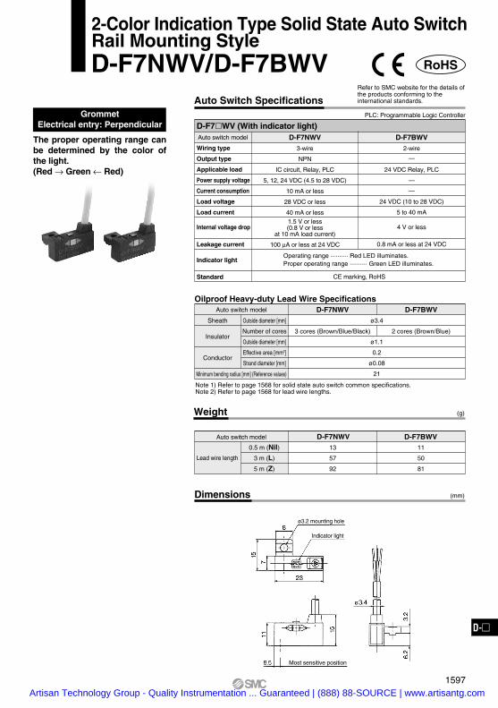
D-F7NWV D-F7BWV
GrommetElectrical entry: Perpendicular
RoHS
2-Color Indication Type Solid State Auto SwitchRail Mounting StyleD-F7NWV/D-F7BWV
The proper operating range can be determined by the color of the light.(Red → Green ← Red)
Note 1) Refer to page 1568 for solid state auto switch common specifications.Note 2) Refer to page 1568 for lead wire lengths.
2 cores (Brown/Blue)
Auto switch model D-F7NWV D-F7BWV
3 cores (Brown/Blue/Black)
Sheath
Insulator
Conductor
Outside diameter [mm]
Number of cores
Outside diameter [mm]
Effective area [mm2]
Strand diameter [mm]
Minimum bending radius [mm] (Reference values)
ø3.4
ø1.1
0.2
ø0.08
21
Oilproof Heavy-duty Lead Wire Specifications
D-F7WV (With indicator light)Auto switch model
Wiring type
Output type
Applicable load
Power supply voltage
Current consumption
Load voltage
Load current
Internal voltage drop
Leakage current
Indicator light
Standard
D-F7BWV
2-wire
—
24 VDC Relay, PLC
—
—
24 VDC (10 to 28 VDC)
5 to 40 mA
4 V or less
0.8 mA or less at 24 VDC
D-F7NWV
3-wire
NPN
IC circuit, Relay, PLC
5, 12, 24 VDC (4.5 to 28 VDC)
10 mA or less
28 VDC or less
40 mA or less
100 µA or less at 24 VDC
1.5 V or less(0.8 V or less
at 10 mA load current)
CE marking, RoHS
Auto Switch SpecificationsRefer to SMC website for the details of the products conforming to the international standards.
PLC: Programmable Logic Controller
Operating range .......... Red LED illuminates.Proper operating range .......... Green LED illuminates.
Dimensions (mm)
ø3.2 mounting hole
Indicator light
Most sensitive position
Lead wire length
1597
D-D-
Artisan Technology Group - Quality Instrumentation ... Guaranteed | (888) 88-SOURCE | www.artisantg.com

Dimensions (mm)
Mounting hole
Indicator light
Most sensitive position
Weight (g)
Auto switch model
0.5 m (Nil)
3 m (L)
5 m (Z)
23
81
127
21
71
111
D-F59W D-F5PW D-J59W
Lead wire length
Grommet
Note 1) Refer to page 1568 for solid state auto switch common specifications.Note 2) Refer to page 1568 for lead wire lengths.
2 cores (Brown/Blue)
Auto switch model D-F59W D-F5PW D-J59W
3 cores (Brown/Blue/Black)
Sheath
Insulator
Conductor
Outside diameter [mm]
Number of cores
Outside diameter [mm]
Effective area [mm2]
Strand diameter [mm]
Minimum bending radius [mm] (Reference values)
ø4
ø1.22
0.3
ø0.08
24
Oilproof Heavy-duty Lead Wire Specifications
RoHS
2-Color Indication Type Solid State Auto SwitchTie-rod Mounting StyleD-F59W/D-F5PW/D-J59W
The proper operating range can be determined by the color of the light.(Red → Green ← Red)
D-F5W, D-J59W (With indicator light)Auto switch model
Wiring type
Output type
Applicable load
Power supply voltage
Current consumption
Load voltage
Load current
Internal voltage drop
Leakage current
Indicator light
Standard
D-F59W
3-wire
NPN
IC circuit, Relay, PLC
5, 12, 24 VDC (4.5 to 28 VDC)
10 mA or less
28 VDC or less
40 mA or less
100 µA or less at 24 VDC
Operating range .......... Red LED illuminates.Proper operating range .......... Green LED illuminates.
D-J59W
2-wire
—
24 VDC Relay, PLC
—
—
24 VDC (10 to 28 VDC)
5 to 40 mA
4 V or less
0.8 mA or less at 24 VDC
D-F5PW
PNP
—
80 mA or less
0.8 V or less1.5 V or less(0.8 V or less
at 10 mA load current)
Auto Switch SpecificationsRefer to SMC website for the details of the products conforming to the international standards.
PLC: Programmable Logic Controller
CE marking, RoHS
1598Artisan Technology Group - Quality Instrumentation ... Guaranteed | (888) 88-SOURCE | www.artisantg.com

ø3.
4
Indicator light
ø3.5 mounting hole
Most sensitive position
Dimensions
Grommet
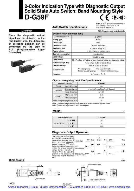
Since the diagnostic output signal can be detected in the red display area, the difference of detecting position can be confirmed by the side of PLC (Programmable Logic Controller).
(mm)
Weight
Auto switch model
0.5 m (Nil)
3 m (L)
5 m (Z)
13
56
90
D-H7NF
(g)
Lead wire length
Note 1) Refer to page 1568 for solid state auto switch common specifications.Note 2) Refer to page 1568 for lead wire lengths.
Auto switch model D-H7NFSheath
Insulator
Conductor
Outside diameter [mm]
Number of cores
Outside diameter [mm]
Effective area [mm2]
Strand diameter [mm]
Minimum bending radius [mm] (Reference values)
ø3.4
4 cores (Brown/Blue/Black/Orange)
ø0.98
0.2
ø0.08
21
Oilproof Heavy-duty Lead Wire Specifications
RoHS
2-Color Indication Type with Diagnostic OutputSolid State Auto Switch: Band Mounting StyleD-H7NF
D-H7NF (With indicator light)Auto switch model
Wiring type
Output type
Diagnostic output
Applicable load
Power voltage
Current consumption
Load voltage
Load current
Internal voltage drop
Current leakage
Indicator light
Standard
D-H7NF
4-wire
NPN
Normal operation
IC circuit, Relay, PLC
5, 12, 24 VDC (4.5 to 28 VDC)
10 mA or less
28 VDC or less
50 mA or less at the total amount of normal output and diagnostic output
1.5 V or less (0.8 V or less at each output 5 mA)
100 µA or less at 24 VDC
CE marking, RoHS
Auto Switch SpecificationsPLC: Programmable Logic Controller
Refer to SMC website for the details of the products conforming to the international standards.
Operating range .......... Red LED illuminates.Proper operating range .......... Green LED illuminates.
Diagnostic Output Operation
Indicator light
OUT(Normal output)
Diagnosis OUT(Diagnostic output)
OFF OFF
ON
Red Green Red Red
The diagnostic output signal is output within the red display area (where indicator light is Red), and the diagnostic output becomes OFF when the detecting position remains within the proper operating range (where indicator is Green). When the detecting position is not adjusted, the diagnostic output becomes ON.
1599
D-D-
Artisan Technology Group - Quality Instrumentation ... Guaranteed | (888) 88-SOURCE | www.artisantg.com
ø4.5 mounting hole
Most sensitive position
Dimensions
Grommet
Since the diagnostic output signal can be detected in the red display area, the difference of detecting position can be confirmed by the side of PLC (Programmable Logic Controller).
(mm)
Weight
Auto switch model
0.5 m (Nil)
3 m (L)
5 m (Z)
20
74
117
D-G59F
(g)
Lead wire length
Note 1) Refer to page 1568 for solid state auto switch common specifications.Note 2) Refer to page 1568 for lead wire lengths.
Auto switch model D-G59FSheath
Insulator
Conductor
Outside diameter [mm]
Number of cores
Outside diameter [mm]
Effective area [mm2]
Strand diameter [mm]
Minimum bending radius [mm] (Reference values)
ø4
4 cores (Brown/Blue/Black/Orange)
ø1.29
0.3
ø0.08
24
Oilproof Heavy-duty Lead Wire Specifications
RoHS
2-Color Indication Type with Diagnostic OutputSolid State Auto Switch: Band Mounting StyleD-G59F
D-G59F (With indicator light)Auto switch model
Wiring type
Output type
Diagnostic output
Applicable load
Power voltage
Current consumption
Load voltage
Load current
Internal voltage drop
Current leakage
Indicator light
Standard
D-G59F
4-wire
NPN
Normal operation
IC circuit, Relay, PLC
5, 12, 24 VDC (4.5 to 28 VDC)
10 mA or less
28 VDC or less
50 mA or less at the total amount of normal output and diagnostic output
1.5 V or less (0.8 V or less at 5 mA)
100 µA or less at 24 VDC
CE marking, RoHS
Auto Switch SpecificationsPLC: Programmable Logic Controller
Refer to SMC website for the details of the products conforming to the international standards.
Operating range .......... Red LED illuminates.Proper operating range .......... Green LED illuminates.
ø4
Indicator light
Diagnostic Output OperationThe diagnostic output signal is output within the red display area (where indicator light is Red), and the diagnostic output becomes OFF when the detecting position remains within the proper operating range (where indicator is Green). When the detecting position is not adjusted, the diagnostic output becomes ON.
Indicator light
OUT(Normal output)
Diagnosis OUT(Diagnostic output)
OFF OFF
ON
Red Green Red Red
1600Artisan Technology Group - Quality Instrumentation ... Guaranteed | (888) 88-SOURCE | www.artisantg.com

The diagnostic output signal is output within the red display area (where indicator light is Red), and it is not output within the proper operating range (where indicator light is Green). When the auto switch detecting position is not adjusted, the diagnostic output becomes activated.
Indicator light
OUT(Normal output)
Diagnosis OUT(Diagnostic output)
Red Green Red Red
Weight
Auto switch model
0.5 m (Nil)
3 m (L)
5 m (Z)
13
56
90
D-F79F
(g)
Grommet
Since the diagnostic output signal can be detected in the red display area, the difference of detecting position can be confirmed by the side of PLC (Programmable Logic Controller).
Lead wire length
Note 1) Refer to page 1568 for solid state auto switch common specifications.Note 2) Refer to page 1568 for lead wire lengths.
Auto switch model D-F79FSheath
Insulator
Conductor
Outside diameter [mm]
Number of cores
Outside diameter [mm]
Effective area [mm2]
Strand diameter [mm]
Minimum bending radius [mm] (Reference values)
ø3.4
4 cores (Brown/Blue/Black/Orange)
ø0.98
0.2
ø0.08
21
Oilproof Heavy-duty Lead Wire Specifications
RoHS
Auto Switch Specifications
D-F79F (With indicator light)Auto switch model
Wiring type
Output type
Diagnostic output
Applicable load
Power supply voltage
Current consumption
Load voltage
Load current
Internal voltage drop
Leakage current
Indicator light
Standard
D-F79F
4-wire
NPN
Normal operation
IC circuit, Relay, PLC
5, 12, 24 VDC (4.5 to 28 VDC)
10 mA or less
28 VDC or less
50 mA or less at the total amount of normal output and diagnostic output
1.5 V or less (0.8 V or less at 5 mA)
100 µA or less at 24 VDC
Operating range .......... Red LED illuminates.Proper operating range .......... Green LED illuminates.
CE marking, RoHS
Refer to SMC website for the details of the products conforming to the international standards.
PLC: Programmable Logic Controller
Dimensions (mm)
ø3.2 Mounting hole
ø3.
4
Most sensitive position
Indicator light
Diagnostic Output Operation
1601
2-Color Indication Type with Diagnostic OutputSolid State Auto Switch: Rail Mounting StyleD-F79F
D-D-
Artisan Technology Group - Quality Instrumentation ... Guaranteed | (888) 88-SOURCE | www.artisantg.com

ø4
Indicator light
Mounting hole
Most sensitive position
Dimensions
Grommet
(mm)
Weight
Auto switch model
0.5 m (Nil)
3 m (L)
5 m (Z)
D-F59F22
77
121
(g)
Lead wire length
Note 1) Refer to page 1568 for solid state auto switch common specifications.Note 2) Refer to page 1568 for lead wire lengths.
Auto switch model D-F59FSheath
Insulator
Conductor
Outside diameter [mm]
Number of cores
Outside diameter [mm]
Effective area [mm2]
Strand diameter [mm]
Minimum bending radius [mm] (Reference values)
ø4
4 cores (Brown/Blue/Black/Orange)
ø1.29
0.3
ø0.08
24
Oilproof Heavy-duty Lead Wire Specifications
RoHS
2-Color Indication Type with Diagnostic OutputSolid State Auto Switch: Tie-rod Mounting StyleD-F59F
Since the diagnostic output signal can be detected in the red display area, the difference of detecting position can be confirmed by the side of PLC (Programmable Logic Controller).
Auto Switch Specifications
D-F59F (With indicator light)Auto switch model
Wiring type
Output type
Diagnostic output
Applicable load
Power supply voltage
Current consumption
Load voltage
Load current
Internal voltage drop
Leakage current
Indicator light
D-F59F
4-wire
NPN
Normal operation
IC circuit, Relay, PLC
5, 12, 24 VDC (4.5 to 28 VDC)
10 mA or less
28 VDC or less
50 mA or less at the total amount of normal output and diagnostic output
1.5 V or less (0.8 V or less at 5 mA)
100 µA or less at 28 VDC
Standard CE marking, RoHS
Refer to SMC website for the details of the products conforming to the international standards.
PLC: Programmable Logic Controller
Operating range .......... Red LED illuminates.Proper operating range .......... Green LED illuminates.
Diagnostic Output Operation
The diagnostic output signal is output within the red display area (where indicator light is Red), and it is not output within the proper operating range (where indicator light is Green). When the auto switch detecting position is not adjusted, the diagnostic output becomes activated.
Indicator light
OUT(Normal output)
Diagnosis OUT(Diagnostic output)
Red GreenOFF OFFRed RedON
1602Artisan Technology Group - Quality Instrumentation ... Guaranteed | (888) 88-SOURCE | www.artisantg.com

Weight (g)
Auto switch model
0.5 m (Nil)1 m (M)
3 m (L)
5 m (Z)
D-M9NA(V)8
14
41
68
D-M9PA(V) D-M9BA(V)7
13
38
63
Lead wire length
Note 1) Refer to page 1568 for solid state auto switch common specifications.Note 2) Refer to page 1568 for lead wire lengths.
DimensionsD-M9A D-M9AV
(mm)
Grommet
Water (coolant) resistant type 2-wire load current is reduced
(2.5 to 40 mA). The proper operating range can
be determined by the color of the light. (Red → Green ← Red)
Using flexible cable as standard spec.
RoHS
2 cores (Brown/Blue)
Auto switch model D-M9NA D-M9PA D-M9BA
3 cores (Brown/Blue/Black)
Sheath
Insulator
Conductor
Outside diameter [mm]
Number of cores
Outside diameter [mm]
Effective area [mm2]
Strand diameter [mm]
Minimum bending radius [mm] (Reference values)
2.7 x 3.2 (ellipse)
ø0.9
0.15
ø0.05
20
Oilproof Flexible Heavy-duty Lead Wire Specifications
Water Resistant 2-Color Indication TypeSolid State Auto Switch: Direct Mounting StyleD-M9NA(V)/D-M9PA(V)/D-M9BA(V)
PrecautionsCaution
Fix the auto switch with the existing screw installed on the auto switch body. The auto switch may be damaged if a screw other than the one supplied is used.Please consult with SMC if using coolantliquid other than water based solution.
Auto switch model
Electrical entry direction
Wiring type
Output type
Applicable load
Power supply voltage
Current consumption
Load voltage
Load current
Internal voltage drop
Leakage current
Indicator light
Standard
D-M9NAVD-M9NA D-M9BA D-M9BAV
2-wire
—
24 VDC relay, PLC
—
—
24 VDC (10 to 28 VDC)
2.5 to 40 mA
4 V or less
0.8 mA or less
D-M9PAVD-M9PA
Operating range .......... Red LED illuminates.Proper operating range .......... Green LED illuminates.
3-wire
IC circuit, Relay, PLC
5, 12, 24 VDC (4.5 to 28 V)
10 mA or less
40 mA or less
0.8 V or less at 10 mA (2 V or less at 40 mA)
100 µA or less at 24 VDC
In-line Perpendicular In-line Perpendicular In-line Perpendicular
NPN PNP
CE marking, RoHS
28 VDC or less —
D-M9A, D-M9AV (With indicator light)
Auto Switch SpecificationsPLC: Programmable Logic Controller
4
0.2
3
SMC4
2.8
24 2.7
Indicator light
M2.5 x 4 L
Slotted set screw
6
3.2
Most sensitive position
2.7
6
2.6
9.3
Most sensitive position
4
SMC
22
3.2
4.6
2.8
4
28
M2.5 x 4 L
Slotted set screwIndicator light
1603
D-D-
Artisan Technology Group - Quality Instrumentation ... Guaranteed | (888) 88-SOURCE | www.artisantg.com
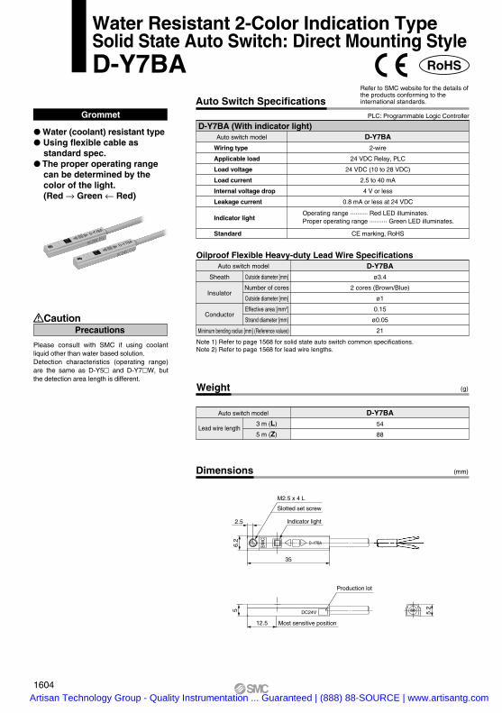
Dimensions
Grommet
Water (coolant) resistant type Using flexible cable as
standard spec. The proper operating range
can be determined by the color of the light. (Red → Green ← Red)
Weight
Auto switch model
3 m (L)
5 m (Z)
D-Y7BA54
88
(g)
Lead wire length
Note 1) Refer to page 1568 for solid state auto switch common specifications.Note 2) Refer to page 1568 for lead wire lengths.
(mm)
Auto switch model D-Y7BASheath
Insulator
Conductor
Outside diameter [mm]
Number of cores
Outside diameter [mm]
Effective area [mm2]
Strand diameter [mm]
Minimum bending radius [mm] (Reference values)
ø3.4
2 cores (Brown/Blue)
ø1
0.15
ø0.05
21
Oilproof Flexible Heavy-duty Lead Wire Specifications
RoHS
Water Resistant 2-Color Indication TypeSolid State Auto Switch: Direct Mounting StyleD-Y7BA
Caution
Please consult with SMC if using coolant liquid other than water based solution.Detection characteristics (operating range) are the same as D-Y5 and D-Y7W, but the detection area length is different.
Precautions
Auto Switch Specifications
D-Y7BA (With indicator light)Auto switch model
Wiring type
Applicable load
Load voltage
Load current
Internal voltage drop
Leakage current
Indicator light
Standard
D-Y7BA
2-wire
24 VDC Relay, PLC
24 VDC (10 to 28 VDC)
2.5 to 40 mA
4 V or less
0.8 mA or less at 24 VDC
CE marking, RoHS
Refer to SMC website for the details of the products conforming to the international standards.
PLC: Programmable Logic Controller
Operating range .......... Red LED illuminates.Proper operating range .......... Green LED illuminates.
5
12.5 Most sensitive position
Production lot
DC24V 5.2
2.5
6.2
35
Indicator light
M2.5 x 4 L
D−Y7BA
SM
C
Slotted set screw
1604Artisan Technology Group - Quality Instrumentation ... Guaranteed | (888) 88-SOURCE | www.artisantg.com
Dimensions
Note 1) Refer to page 1568 for solid state auto switch common specifications.Note 2) Refer to page 1568 for lead wire lengths.
Weight
Auto switch model
3 m (L)
5 m (Z)
(g)
(mm)
Lead wire length
D-H7BA50
81
Auto switch model D-H7BASheath
Insulator
Conductor
Outside diameter [mm]
Number of cores
Outside diameter [mm]
Effective area [mm2]
Strand diameter [mm]
Minimum bending radius [mm] (Reference values)
ø3.4
2 cores (Brown/Blue)
ø1.1
0.2
ø0.08
21
Oilproof Heavy-duty Lead Wire Specifications
RoHS
Water Resistant 2-Color Indication TypeSolid State Auto Switch: Band Mounting StyleD-H7BA
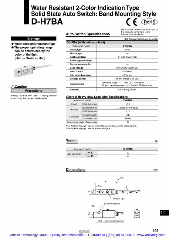
Grommet
Water (coolant) resistant type The proper operating range
can be determined by the color of the light.(Red → Green ← Red)
PrecautionsCaution
Please consult with SMC if using coolant liquid other than water based solution.
D-H7BA (With indicator light)Auto switch model
Wiring type
Output type
Applicable load
Power supply voltage
Current consumption
Load voltage
Load current
Internal voltage drop
Leakage current
Indicator light
D-H7BA
2-wire
—
24 VDC Relay, PLC
—
—
24 VDC (10 to 28 VDC)
5 to 40 mA
4 V or less
0.8 mA or less at 24 VDC
Standard CE marking, RoHS
Auto Switch SpecificationsPLC: Programmable Logic Controller
Refer to SMC website for the details of the products conforming to the international standards.
Operating range .......... Red LED illuminates.Proper operating range .......... Green LED illuminates.
ø3.
4
ø3.5 mounting hole
Most sensitive position
Indicator light
1605
D-D-
Artisan Technology Group - Quality Instrumentation ... Guaranteed | (888) 88-SOURCE | www.artisantg.com

Weight
Auto switch model
3 m (L)
5 m (Z)
D-G5BA68
108
(g)
Lead wire length
Note 1) Refer to page 1568 for solid state auto switch common specifications.Note 2) Refer to page 1568 for lead wire lengths.
Auto switch model D-G5BASheath
Insulator
Conductor
Outside diameter [mm]
Number of cores
Outside diameter [mm]
Effective area [mm2]
Strand diameter [mm]
Minimum bending radius [mm] (Reference values)
ø4
2 cores (Brown/Blue)
ø1.22
0.3
ø0.08
24
Oilproof Heavy-duty Lead Wire Specifications
RoHS
Water Resistant 2-Color Indication TypeSolid State Auto Switch: Band Mounting StyleD-G5BA
Grommet
Water (coolant) resistant type The proper operating range
can be determined by the color of the light.(Red → Green ← Red)
PrecautionsCaution
Please consult with SMC if using coolant liquid other than water based solution.
D-G5BA (With indicator light)Auto switch model
Wiring type
Output type
Applicable load
Power supply voltage
Current consumption
Load voltage
Load current
Internal voltage drop
Leakage current
Indicator light
D-G5BA
2-wire
—
24 VDC Relay, PLC
—
—
24 VDC (10 to 28 VDC)
5 to 40 mA
4 V or less
0.8 mA or less at 24 VDC
Standard CE marking, RoHS
Auto Switch SpecificationsPLC: Programmable Logic Controller
Refer to SMC website for the details of the products conforming to the international standards.
Operating range .......... Red LED illuminates.Proper operating range .......... Green LED illuminates.
Dimensions (mm)
ø4
ø4.5 mounting hole
Most sensitive position
Indicator light
1606Artisan Technology Group - Quality Instrumentation ... Guaranteed | (888) 88-SOURCE | www.artisantg.com

8.5
15
6.2
3.2
11
23
SM
C
8
7
15
ø3.4
ø3.2 mounting hole
Most sensitive position
Indicator lightIndicator light
ø3.2 mounting hole
Most sensitive position
Dimensions
Note 1) Refer to page 1568 for solid state auto switch common specifications.Note 2) Refer to page 1568 for lead wire lengths.
Weight
Auto switch model
3 m (L)
5 m (Z)
D-F7BA50
81
D-F7BAV
(g)
(mm)
Lead wire length
D-F7BA D-F7BAV
Auto switch model D-F7BASheath
Insulator
Conductor
Outside diameter [mm]
Number of cores
Outside diameter [mm]
Effective area [mm2]
Strand diameter [mm]
Minimum bending radius [mm] (Reference values)
ø3.4
2 cores (Brown/Blue)
ø1.1
0.2
ø0.08
21
Oilproof Heavy-duty Lead Wire Specifications
RoHS
Water Resistant 2-Color Indication TypeSolid State Auto Switch: Rail Mounting StyleD-F7BA(V)
Grommet
Water (coolant) resistant type The proper operating range
can be determined by the color of the light. (Red → Green ← Red)
PrecautionsCaution
Please consult with SMC if using coolant liquid other than water based solution.
Auto Switch Specifications
D-F7BA(V) (With indicator light)Auto switch model
Electrical entry direction
Wiring type
Output type
Applicable load
Power supply voltage
Current consumption
Load voltage
Load current
Internal voltage drop
Leakage current
Indicator light
2-wire
—
24 VDC Relay, PLC
—
—
24 VDC (10 to 28 VDC)
5 to 40 mA
4 V or less
0.8 mA or less at 24 VDC
D-F7BAV
Perpendicular
D-F7BA
In-line
Standard CE marking, RoHS
Refer to SMC website for the details of the products conforming to the international standards.
PLC: Programmable Logic Controller
Operating range .......... Red LED illuminates.Proper operating range .......... Green LED illuminates.
1607
D-D-
Artisan Technology Group - Quality Instrumentation ... Guaranteed | (888) 88-SOURCE | www.artisantg.com

Weight
Auto switch model
3 m (L)
5 m (Z)
(g)
(mm)
Lead wire length
D-F5BA71
111
Dimensions
Note 1) Refer to page 1568 for solid state auto switch common specifications.Note 2) Refer to page 1568 for lead wire lengths.
Auto switch model D-F5BASheath
Insulator
Conductor
Outside diameter [mm]
Number of cores
Outside diameter [mm]
Effective area [mm2]
Strand diameter [mm]
Minimum bending radius [mm] (Reference values)
ø4
2 cores (Brown/Blue)
ø1.22
0.3
ø0.08
24
Oilproof Heavy-duty Lead Wire Specifications
RoHS
Water Resistant 2-Color Indication TypeSolid State Auto Switch: Tie-rod Mounting StyleD-F5BA
Grommet
Water (coolant) resistant type The proper operating range
can be determined by the color of the light. (Red → Green ← Red)
Caution
Please consult with SMC if using coolant liquid other than water based solution.
Precautions
Auto Switch Specifications
Auto switch model
Wiring type
Output type
Applicable load
Power supply voltage
Current consumption
Load voltage
Load current
Internal voltage drop
Leakage current
Indicator light
D-F5BA
2-wire
—
24 VDC Relay, PLC
—
—
24 VDC (10 to 28 VDC)
5 to 40 mA
4 V or less
0.8 mA or less at 24 VDC
D-F5BA (With indicator light)
Standard CE marking, RoHS
Refer to SMC website for the details of the products conforming to the international standards.
PLC: Programmable Logic Controller
Operating range .......... Red LED illuminates.Proper operating range .......... Green LED illuminates.
ø4
Mounting hole
Most sensitive position
Indicator light
1608Artisan Technology Group - Quality Instrumentation ... Guaranteed | (888) 88-SOURCE | www.artisantg.com

Weight
Auto switch model
0.5 m (Nil)3 m (L)
5 m (Z)
D-F6N D-F6P D-F6B
20
53
80
19
50
75
(g)
Lead wire length
Dimensions
D-F6 D-F6B
D-F6N/F6P
(mm)
2 cores (Brown/Blue)
Auto switch model D-F6N D-F6P D-F6B
3 cores (Brown/Blue/Black)
Sheath
Insulator
Conductor
Outside diameter [mm]
Number of cores
Outside diameter [mm]
Effective area [mm2]
Strand diameter [mm]
Minimum bending radius [mm] (Reference values)
2.7 x 3.2 (ellipse)
ø0.9
0.15
ø0.05
20
Oilproof Flexible Heavy-duty Lead Wire Specifications
RoHS
For Hygienic Design CylindersSolid State Auto Switch: Direct Mounting StyleD-F6N/D-F6P/D-F6B
Grommet
2-wire load current is reduced (2.5 to 40 mA)
Using flexible cable as standard spec.
PrecautionsCaution
Fix the auto switch with the existing screw installed on the auto switch body. The auto switch may be damaged if a screw other than the one supplied is used.
Auto switch part no.
Electrical entry direction
Wiring type
Output type
Applicable load
Power supply voltage
Current consumption
Load voltage
Load current
Internal voltage drop
Leakage current
Indicator light
Standard
D-F6N D-F6B
2-wire
—
24 VDC relay, PLC
—
—
24 VDC (10 to 28 VDC)
2.5 to 40 mA
4 V or less
0.8 mA or less
D-F6P
Red LED illuminates when turned ON.
CE marking, RoHS
3-wire
IC circuit, relay, and PLC
5, 12, 24 VDC (4.5 to 28 V)
10 mA or less
40 mA or less
0.8 V or less at 10 mA (2V or less at 40 mA)
100 µA or less at 24 V DC
In-line
NPN PNP
28 VDC or less —
D-F6 (With indicator light)
Auto Switch SpecificationsPLC: Programmable Logic Controller
8.5
29
(24) 16
10.6 ø7 2.7
Indicator light
(22)
7
3.2
Most sensitive position
(22)
7
3.2
Most sensitive position
Note 1) Refer to page 1568 for solid state auto switch common specifications.Note 2) Refer to page 1568 for lead wire lengths.
1609
D-D-
Artisan Technology Group - Quality Instrumentation ... Guaranteed | (888) 88-SOURCE | www.artisantg.com

ø4.5 mounting hole
Most sensitive position
ø4
Indicator light
Dimensions
Weight
Auto switch model
3 m (L)
5 m (Z)
D-G5NT78
124
(g)
(mm)
Lead wire length
Note 1) Refer to page 1568 for solid state auto switch common specifications.Note 2) Refer to page 1568 for lead wire lengths.
Auto switch model D-G5NTSheath
Insulator
Conductor
Outside diameter [mm]
Number of cores
Outside diameter [mm]
Effective area [mm2]
Strand diameter [mm]
Minimum bending radius [mm] (Reference values)
ø4
3 cores (Brown/Blue/Black)
ø1.22
0.3
ø0.08
24
Oilproof Heavy-duty Lead Wire Specifications
RoHS
Solid State Auto Switch with TimerBand Mounting StyleD-G5NT
Grommet
With built-in OFF-delay timer (approx. 200 ms)
Easy intermediate detection
D-G5NT (With indicator light)Auto switch model
Wiring type
Output type
Output operation
Operating time
Off-delay time
Applicable load
Power supply voltage
Current consumption
Load voltage
Load current
Internal voltage drop
Leakage current
Indicator light
Standard
D-G5NT3-wire
NPN
Off-delay
1 ms or less
200 ± 50 ms
IC circuit, Relay, PLC
5, 12, 24 VDC (4.5 to 28 VDC)
10 mA or less
28 VDC or less
40 mA or less
1.5 V or less (0.8 V or less at 10 mA)
100 µA or less at 24 VDC
Red LED illuminates when turned ON.
CE marking, RoHS
Auto Switch SpecificationsPLC: Programmable Logic Controller
Refer to SMC website for the details of the products conforming to the international standards.
Timer Operation
Detection of intermediate positioning for high-speed cylinderDetecting point dispersion occurs due to response time of PLC (sequencer); e.g. scanning.
Ex.) Cylinder speed — 1000 mm/sec.PLC response time — 0.1 sec.Detecting point dispersion — Within 100 mm (= 1000 mm/sec. x 0.1 sec.)
Take PLC response time into consider-ation when using.
Auto switch detecting time
Auto switch output ON time
PLC response time
Auto switch operating range (mm)Cylinder speed (mm/s)
1610Artisan Technology Group - Quality Instrumentation ... Guaranteed | (888) 88-SOURCE | www.artisantg.com

ø3.2 mounting hole
Indicator light
Dimensions
Weight
Auto switch model
3 m (L)
5 m (Z)
D-F7NT57
92
(g)
(mm)
Lead wire length
Note 1) Refer to page 1568 for solid state auto switch common specifications.Note 2) Refer to page 1568 for lead wire lengths.
Auto switch model D-F7NTSheath
Insulator
Conductor
Outside diameter [mm]
Number of cores
Outside diameter [mm]
Effective area [mm2]
Strand diameter [mm]
Minimum bending radius [mm] (Reference values)
ø3.4
3 cores (Brown/Blue/Black)
ø1.1
0.2
ø0.08
21
Oilproof Heavy-duty Lead Wire Specifications
RoHS
Solid State Auto Switch with TimerRail Mounting StyleD-F7NT
Grommet
With built-in OFF-delay timer (approx. 200 ms)
Easy intermediate detection
D-F7NT (With indicator light)Auto switch model
Wiring type
Output type
Output operation
Operating time
Off-delay time
Applicable load
Power supply voltage
Current consumption
Load voltage
Load current
Internal voltage drop
Leakage current
Indicator light
Standard
D-F7NT3-wire
NPN
Off-delay
1 ms or less
200 ± 50 ms
IC circuit, Relay, PLC
5, 12, 24 VDC (4.5 to 28 VDC)
10 mA or less
28 VDC or less
40 mA or less
1.5 V or less (0.8 V or less at 10 mA)
100 µA or less at 24 VDC
Red LED illuminates when turned ON.
CE marking, RoHS
Auto Switch SpecificationsRefer to SMC website for the details of the products conforming to the international standards.
PLC: Programmable Logic Controller
Timer Operation
Detection of intermediate positioning for high-speed cylinderDetecting point dispersion occurs due to response time of PLC (sequencer); e.g. scanning.
Ex.) Cylinder speed — 1000 mm/sec.PLC response time — 0.1 sec.Detecting point dispersion — Within 100 mm (= 1000 mm/sec. x 0.1 sec.)
Take PLC response time into consider-ation when using.
Switch detecting time
Switch output ON time
PLC response time
Switch operating range (mm)Cylinder speed (mm/s)
ø3.
4
Most sensitive position
1611
D-D-
Artisan Technology Group - Quality Instrumentation ... Guaranteed | (888) 88-SOURCE | www.artisantg.com

Dimensions
Timer Operation
Note 1) Refer to page 1568 for solid state auto switch common specifications.Note 2) Refer to page 1568 for lead wire lengths.
Weight
Auto switch model
3 m (L)
5 m (Z)
(g)
(mm)
Lead wire length
D-F5NT81
127
Auto switch model D-F5NTSheath
Insulator
Conductor
Outside diameter [mm]
Number of cores
Outside diameter [mm]
Effective area [mm2]
Strand diameter [mm]
Minimum bending radius [mm] (Reference values)
ø4
3 cores (Brown/Blue/Black)
ø1.22
0.3
ø0.08
24
Oilproof Heavy-duty Lead Wire Specifications
RoHS
Solid State Auto Switch with TimerTie-rod Mounting StyleD-F5NT
Grommet
With built-in OFF-delay timer (approx. 200 ms)
Easy intermediate detection
Detection of intermediate positioning for high-speed cylinderDetecting point dispersion occurs due to response time of PLC (sequencer); e.g. scanning.
Ex.) Cylinder speed — 1000 mm/sec.PLC response time — 0.1 sec.Detecting point dispersion — Within 100 mm (= 1000 mm/sec. x 0.1 sec.)
Take PLC response time into consider-ation when using.
Switch detecting time
Switch output ON time
PLC response time
Switch operating range (mm)Cylinder speed (mm/s)
D-F5NT (With indicator light)Auto switch model
Wiring type
Output type
Output operation
Operating time
Off-delay time
Applicable load
Power supply voltage
Current consumption
Load voltage
Load current
Internal voltage drop
Leakage current
Indicator light
Standard
D-F5NT3-wire
NPN
Off-delay
1 ms or less
200 ± 50 ms
IC circuit, Relay, PLC
5, 12, 24 VDC (4.5 to 28 VDC)
10 mA or less
28 VDC or less
40 mA or less
1.5 V or less (0.8 V or less at 10 mA)
100 µA or less at 24 VDC
Red LED illuminates when turned ON.
CE marking, RoHS
Auto Switch SpecificationsRefer to SMC website for the details of the products conforming to the international standards.
PLC: Programmable Logic Controller
ø4
Indicator light
Mounting hole
Most sensitive position
1612Artisan Technology Group - Quality Instrumentation ... Guaranteed | (888) 88-SOURCE | www.artisantg.com
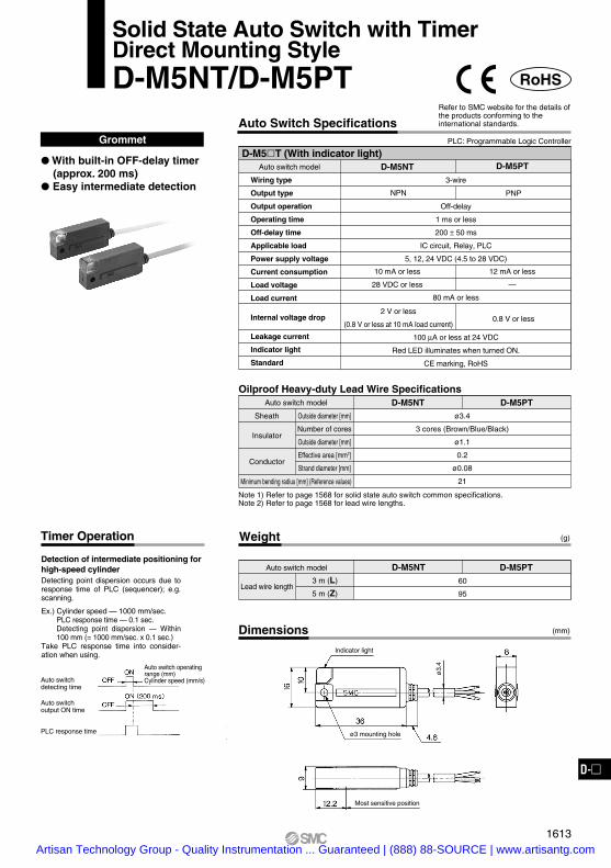
Dimensions
Weight
Auto switch model
3 m (L)
5 m (Z)
D-M5NT60
95
D-M5PT
(g)
(mm)
Lead wire length
Timer Operation
Note 1) Refer to page 1568 for solid state auto switch common specifications.Note 2) Refer to page 1568 for lead wire lengths.
Auto switch model D-M5NT D-M5PTSheath
Insulator
Conductor
Outside diameter [mm]
Number of cores
Outside diameter [mm]
Effective area [mm2]
Strand diameter [mm]
Minimum bending radius [mm] (Reference values)
ø3.4
3 cores (Brown/Blue/Black)
ø1.1
0.2
ø0.08
21
Oilproof Heavy-duty Lead Wire Specifications
RoHS
Solid State Auto Switch with TimerDirect Mounting StyleD-M5NT/D-M5PT
Grommet
With built-in OFF-delay timer (approx. 200 ms)
Easy intermediate detection
Auto switch detecting time
Auto switch output ON time
PLC response time
Auto switch operating range (mm)Cylinder speed (mm/s)
Detection of intermediate positioning for high-speed cylinderDetecting point dispersion occurs due to response time of PLC (sequencer); e.g. scanning.
Ex.) Cylinder speed — 1000 mm/sec.PLC response time — 0.1 sec.Detecting point dispersion — Within 100 mm (= 1000 mm/sec. x 0.1 sec.)
Take PLC response time into consider-ation when using.
D-M5T (With indicator light)Auto switch model
Wiring type
Output type
Output operation
Operating time
Off-delay time
Applicable load
Power supply voltage
Current consumption
Load voltage
Load current
Internal voltage drop
Leakage current
Indicator light
Standard
D-M5NT D-M5PT
3-wire
NPN PNP
Off-delay
1 ms or less
200 ± 50 ms
IC circuit, Relay, PLC
5, 12, 24 VDC (4.5 to 28 VDC)
10 mA or less
28 VDC or less
12 mA or less
—
80 mA or less
2 V or less
(0.8 V or less at 10 mA load current)
100 µA or less at 24 VDC
Red LED illuminates when turned ON.
CE marking, RoHS
0.8 V or less
Auto Switch SpecificationsPLC: Programmable Logic Controller
Refer to SMC website for the details of the products conforming to the international standards.
ø3.
4
ø3 mounting hole
Indicator light
Most sensitive position
1613
D-D-
Artisan Technology Group - Quality Instrumentation ... Guaranteed | (888) 88-SOURCE | www.artisantg.com

6
29 300
ø4.
8
ø14
42.5
Indicator lightConnector size M12
(29)4.7
Most sensitive position(15.2)
33.7
4
6.2
4
4.7 (29)
Most sensitive position(15.2)
33.7
10.5Most sensitive position
Heat shrink tube Note)
111
Applicable to 300 mm pre-wired connector
Note) A white color heat shrink tube is attached to the D-P3DWSE type only.
∗ When the auto switch is ordered on its own, the auto switch mounting bracket is not enclosed. In that case, please order it separately.
Magnetic Field Resistance DimensionsIf the current of the AC welding machine is 16000 A or lower, the auto switch can be used, even if the distance between the welding conductor (gun cable) and the cylinder/actuator or auto switch is 0 mm.Please contact SMC when the AC welding current exceeds 16000 A.
Connector pin
43
2 1
(mm)
(g)Weight
Auto switch model
Lead wire length (m) 0.3 23
D-P3DWSC D-P3DWSE
Body
Auto switch model D-P3DWSC D-P3DWSESheath
Insulator
Conductor
Outside diameter [mm]
Number of cores
Outside diameter [mm]
Effective area [mm2]
Strand diameter [mm]
Minimum bending radius [mm] (Reference values)
ø4.8
2 cores
ø1.52
0.5
ø0.08
29
Oilproof Heavy-duty Lead Wire Specifications
®
RoHS
Magnetic Field Resistant 2-Color Indication Type Solid State Auto SwitchD-P3DWSC/D-P3DWSE (Electrical Entry: Pre-wired connector)
It is possible to use in an environment which generates a magnetic field disturbance (AC magnetic field).
The proper operating range can be determined by the color of the light.(Red → Green ← Red)
PrecautionsCaution
For single-phase AC welding machinesIf it is used for current inverter welders (including rectifying type) and condenser type welders, the magnetic field resistance is reduced. Please contact SMC regarding the performance.
Auto Switch SpecificationsPLC: Programmable Logic Controller
Auto switch model
Applicable load
Load voltage
Load current
Internal voltage drop
Leakage current
Operating time
Indicator light
Standard
24 VDC relay, PLC
24 VDC
6 to 40 mA or less
5 V or less
1 mA or less at 24 VDC
40 ms or less
CE marking, UL (CSA), RoHS
Operating range .......... Red LED illuminates.Proper operating range .......... Green LED illuminates.
D-P3DWSC/E (With indicator light)D-P3DWSC D-P3DWSE
Refer to SMC website for the details of the products conforming to the international standards.
Impact resistance — Switch: 1000 m/s2, Connector: 300 m/s2
Insulation resistance — 50 MΩ or more (500 VDC measured via megohmmeter) (between lead wire and case) Withstand voltage — 1000 VAC for 1 minute (between lead wire and case) Ambient temperature — –10 to 60°C Enclosure — IEC60529 standard IP67 Polarity: Non-polar
Auto switch mounting bracket(For round groove mounting: BQ6-032S)
Auto switch mounting bracket(For square groove mounting: BMG6-025S)
Model1 2 3 4
Connector pin/Wiring
—
OUT(±)
—
—
OUT( )
—
OUT(±)
OUT( )
D-P3DWSC
D-P3DWSE
±
±
1614Artisan Technology Group - Quality Instrumentation ... Guaranteed | (888) 88-SOURCE | www.artisantg.com

10.5
111
(29)4.7
6
29 500, (3000, 5000)
Indicator light
ø4.
8
Most sensitive position(15.2)
33.7
4
6.2
4
4.7 (29)
Most sensitive position(15.2)
33.7
Most sensitive position
∗ When the auto switch is ordered on its own, the auto switch mounting bracket is not enclosed. In that case, please order it separately.
Impact resistance — Switch: 1000 m/s2
Insulation resistance — 50 MΩ or more (500 VDC measured via megohmmeter) (between lead wire and case) Withstand voltage — 1000 VAC for 1 minute (between lead wire and case) Ambient temperature — –10 to 60°C Enclosure — IEC60529 standard IP67 Polarity: Non-polar
Auto switch model
Lead wire length
0.5 m (Nil)
3 m (L)
5 m (Z)
20
102
168
D-P3DW
Dimensions (mm)Magnetic Field Resistance
If the current of the AC welding machine is 16000 A or lower, the auto switch can be used, even if the distance between the welding conductor (gun cable) and the cylinder/actuator or auto switch is 0 mm.Please contact SMC when the AC welding current exceeds 16000 A.
(g)Weight
Body
Auto switch model D-P3DWSheath
Insulator
Conductor
Outside diameter [mm]
Number of cores
Outside diameter [mm]
Effective area [mm2]
Strand diameter [mm]
Minimum bending radius [mm] (Reference values)
ø4.8
2 cores (Brown/Blue)
ø1.52
0.5
ø0.08
29
Oilproof Heavy-duty Lead Wire Specifications
®
RoHS
Magnetic Field Resistant 2-Color Indication Type Solid State Auto SwitchD-P3DW(Electrical Entry: Grommet)
It is possible to use in an environment which generates a magnetic field disturbance (AC magnetic field).
The proper operating range can be determined by the color of the light.(Red → Green ← Red)
PrecautionsCaution
For single-phase AC welding machinesIf it is used for current inverter welders (including rectifying type) and condenser type welders, the magnetic field resistance is reduced. Please contact SMC regarding the performance.
PLC: Programmable Logic Controller
Auto switch model
Applicable load
Load voltage
Load current
Internal voltage drop
Leakage current
Operating time
Indicator light
Standard
24 VDC relay, PLC
24 VDC
6 to 40 mA or less
5 V or less
1 mA or less at 24 VDC
40 ms or less
CE marking, UL (CSA), RoHS
Operating range .......... Red LED illuminates.Proper operating range .......... Green LED illuminates.
D-P3DW (With indicator light)D-P3DW
Auto Switch SpecificationsRefer to SMC website for the details of the products conforming to the international standards.
Auto switch mounting bracket(For round groove mounting: BQ6-032S)
Auto switch mounting bracket(For square groove mounting: BMG6-025S)
1615
D-D-
Artisan Technology Group - Quality Instrumentation ... Guaranteed | (888) 88-SOURCE | www.artisantg.com

300
ø4.
8
ø14
42.5
Connector size M12
Heat shrink tube Note)
For pre-wiredconnector(300 mm)
D-P3DWA
111
Most sensitive position10.5
293
6
Indicator light
Switch mounting thread M2.5 x 12L SUS
3.95
3.3
14.3
It is possible to use in an environment which generates a magnetic field disturbance (AC magnetic field).
The proper operating range can be determined by the color of the light.(Red → Green ← Red)
Magnetic Field Resistance
If the current of the AC welding machine is 16000 A or lower, the auto switch can be used, even if the distance between the welding conductor (gun cable) and the cylinder/actuator or auto switch is 0 mm.Please contact SMC when the AC welding current exceeds 16000 A.
Connector pin
43
2 1
(g)Weight
Auto switch model
Lead wire length (m) 0.3
D-P3DWASC D-P3DWASE
Model1 2 3 4
Connector pin and wiring
—
OUT(±)
—
—
OUT( )
—
OUT(±)
OUT( )
D-P3DWASC
D-P3DWASE
25
Auto Switch SpecificationsPLC: Programmable Logic Controller
Auto switch model
Applicable load
Load voltage
Load current
Internal voltage drop
Leakage current
Operating time
Indicator light
Standard
24 VDC relay, PLC
24 VDC
6 to 40 mA
5 V or less
1 mA or less at 24 VDC
40 ms or less
CE marking, UL (CSA), RoHS
Operating range .......... Red LED illuminates.Proper operating range .......... Green LED illuminates.
D-P3DWASC/E (With indicator light)D-P3DWASC D-P3DWASE
Dimensions (mm)
Body
Auto switch models D-P3DWASC D-P3DWASESheath
Insulator
Conductor
Outside diameter [mm]
Number of cores
Outside diameter [mm]
Effective area [mm2]
Strand diameter [mm]
Minimum bending radius [mm] (Reference values)
ø4.8
2 cores
ø1.52
0.5
ø0.08
29
Oilproof Heavy-duty Cord Specifications
Note) A white color heat shrink tube is attached to the D-P3DWASE type only.
Magnetic Field Resistant 2-Color Indication TypeSolid State Auto SwitchD-P3DWASC/D-P3DWASE (Electrical Entry: Pre-wired connector)
PrecautionsCaution
For single-phase AC welding machinesIf it is used for current inverter welders (including rectifying type) and condenser type welders, the magnetic field resistance is reduced. Please contact SMC regarding the performance.
Refer to SMC website for the details of the products conforming to the international standards.
Impact resistance — Switch: 1000 m/s2, Connector: 300 m/s2
Insulation resistance — 50 MΩ or more at 500 VDC Mega (between lead wire and case) Withstand voltage — 1000 VAC for 1 minute (between lead wire and case) Ambient temperature — –10 to 60°C Enclosure — IEC60529 standard IP67 Polarity: Non-polar
±
±
®
1317-3B
Artisan Technology Group - Quality Instrumentation ... Guaranteed | (888) 88-SOURCE | www.artisantg.com

D-P3DWA
111
Most sensitive position10.5
500 (3000) (5000)293
6
Indicator light
Switch mounting thread M2.5 x 12L SUS
ø4.
8
3.95
3.3
14.3
It is possible to use in an environment which generates a magnetic field disturbance (AC magnetic field).
The proper operating range can be determined by the color of the light.(Red → Green ← Red)
Auto switch model
Lead wirelength
0.5 m (Nil)
3 m (L)
5 m (Z)
D-P3DWA
Magnetic Field Resistance
If the current of the AC welding machine is 16000 A or lower, the auto switch can be used, even if the distance between the welding con-ductor (gun cable) and the cylinder/actuator or auto switch is 0 mm. Please contact SMC when the AC welding current exceeds 16000 A.
(g)Weight
22
104
170
Auto Switch SpecificationsPLC: Programmable Logic Controller
Auto switch model
Applicable load
Load voltage
Load current
Internal voltage drop
Leakage current
Operating time
Indicator light
Standard
24 VDC relay, PLC
24 VDC
6 to 40 mA
5 V or less
1 mA or less at 24 VDC
40 ms or less
CE marking, UL (CSA), RoHS
Operating range .......... Red LED illuminates.Proper operating range .......... Green LED illuminates.
D-P3DWA (With indicator light)D-P3DWA
Dimensions (mm)
Body
Auto switch models D-P3DWASheath
Insulator
Conductor
Outside diameter [mm]
Number of cores
Outside diameter [mm]
Effective area [mm2]
Strand diameter [mm]
Minimum bending radius [mm] (Reference values)
ø4.8
2 cores (Brown/Blue)
ø1.52
0.5
ø0.08
29
Oilproof Heavy-duty Cord Specifications
Magnetic Field Resistant 2-Color Indication TypeSolid State Auto SwitchD-P3DWA(Electrical Entry: Grommet)
PrecautionsCaution
For single-phase AC welding machinesIf it is used for current inverter welders (including rectifying type) and condenser type welders, the magnetic field resistance is reduced. Please contact SMC regarding the performance.
Refer to SMC website for the details of the products conforming to the international standards.
Impact resistance — Switch: 1000 m/s2
Insulation resistance — 50 MΩ or more at 500 VDC Mega (between lead wire and case) Withstand voltage — 1000 VAC for 1 minute (between lead wire and case) Ambient temperature — –10 to 60°C Enclosure — IEC60529 standard IP67 Polarity: Non-polar
®
1317-4 B
Artisan Technology Group - Quality Instrumentation ... Guaranteed | (888) 88-SOURCE | www.artisantg.com

Impact resistance — Switch: 1000 m/s2, Connector: 300 m/s2
Note 1) Refer to page 1568 for solid state auto switch common specifications.Note 2) Refer to page 1568 for lead wire lengths.
Magnetic Field Resistance
Dimensions
If the current of the AC welding machine is 16000 A or lower, the auto switch can be used, even if the distance between the welding conductor (gun cable) and the cylinder or switch is 0 mm.Please contact SMC when the AC welding current exceeds 16000 A.
Connector pin
(mm)
43
2 1
Weight
Auto switch model
(g)
D-P4DWSC35
D-P4DWSE
Auto switch model D-P4DWSC D-P4DWSESheath
Insulator
Conductor
Outside diameter [mm]
Number of cores
Outside diameter [mm]
Effective area [mm2]
Strand diameter [mm]
Minimum bending radius [mm] (Reference values)
ø6
2 cores
ø2.3
0.5
ø0.08
48
Oilproof Heavy-duty Lead Wire Specifications
RoHS
Magnetic Field Resistant 2-Color Indication Type Solid State Auto SwitchD-P4DWSC/D-P4DWSE(Electrical Entry: Pre-wired connector)
Grommet
It is possible to use in an environment which generates a magnetic field disturbance (AC magnetic field).
The proper operating range can be determined by the color of the light.(Red → Green ← Red)
Auto switch model
Applicable load
Load voltage
Load current
Internal voltage drop
Leakage current
Operating time
Indicator light
Standard
24 VDC relay, PLC
24 VDC (20 to 28 VDC)
6 to 40 mA or less
5 V or less
1 mA or less at 24 VDC
40 ms or less
CE marking, RoHS
D-P4DWS (With indicator light)D-P4DWSC D-P4DWSE
Auto Switch SpecificationsPLC: Programmable Logic Controller
Refer to SMC website for the details of the products conforming to the international standards.
Operating range .......... Red LED illuminates.Proper operating range .......... Green LED illuminates.
PrecautionsCaution
For single-phase AC welding machines.Not applicable for DC inverter welding machines (including rectifying type) and or condenser type welding.
13
30032 4
9.2
8.8
ø6
6
6
120
ø14
44
D-P4DW (24 VDC)SMC
Most sensitive position
Connector size M12
2 x ø3.5 mounting hole
Indicator light
Heat shrink tube Note)
Note) Only for D-P4DWSEPrinted contents: SE 1-4
Model1 2 3 4
Connector pin/Wiring
—
OUT(±)
—
—
OUT( )
—
OUT(±)
OUT( )
D-P4DWSC
D-P4DWSE
±
±
1616Artisan Technology Group - Quality Instrumentation ... Guaranteed | (888) 88-SOURCE | www.artisantg.com
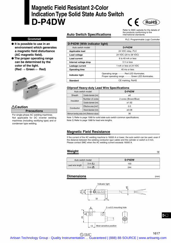
Note 1) Refer to page 1568 for solid state auto switch common specifications.Note 2) Refer to page 1568 for lead wire lengths.
Magnetic Field Resistance
Dimensions
If the current of the AC welding machine is 16000 A or lower, the auto switch can be used, even if the distance between the welding conductor (gun cable) and the cylinder or switch is 0 mm.Please contact SMC when the AC welding current exceeds 16000 A.
(mm)
Weight
Auto switch model
3 m (L)
5 m (Z)
(g)
Lead wire length
D-P4DW150
244
Auto switch model D-P4DWSheath
Insulator
Conductor
Outside diameter [mm]
Number of cores
Outside diameter [mm]
Effective area [mm2]
Strand diameter [mm]
Minimum bending radius [mm] (Reference values)
ø6
2 cores (Brown/Blue)
ø1.92
0.5
ø0.08
36
Oilproof Heavy-duty Lead Wire Specifications
RoHS
Magnetic Field Resistant 2-Color Indication Type Solid State Auto SwitchD-P4DW
Grommet
It is possible to use in an environment which generates a magnetic field disturbance (AC magnetic field).
The proper operating range can be determined by the color of the light.(Red → Green ← Red)
PrecautionsCaution
For single-phase AC welding machines.Not applicable for DC inverter welding machines (including rectifying type) and or condenser type welding.
Auto switch model
Applicable load
Load voltage
Load current
Internal voltage drop
Leakage current
Operating time
Indicator light
Standard
24 VDC relay, PLC
24 VDC (20 to 28 VDC)
6 to 40 mA or less
5 V or less
1 mA or less at 24 VDC
40 ms or less
CE marking, RoHS
D-P4DW (With indicator light)D-P4DW
Auto Switch SpecificationsPLC: Programmable Logic Controller
Refer to SMC website for the details of the products conforming to the international standards.
Operating range .......... Red LED illuminates.Proper operating range .......... Green LED illuminates.
ø6
13
32 4
9.2
8.8
6
61
20
D-P4DW (24 VDC)SMC
2 x ø3.5 mounting hole
Indicator light
Most sensitive position
1617
D-D-
Artisan Technology Group - Quality Instrumentation ... Guaranteed | (888) 88-SOURCE | www.artisantg.com

Dimensions
Weight
Auto switch model
3 m (L)
5 m (Z)
(g)
(mm)
Lead wire length
D-F7NJ170
210
Auto switch model D-F7NJSheath
Insulator
Conductor
Outside diameter [mm]
Number of cores
Outside diameter [mm]
Effective area [mm2]
Strand diameter [mm]
Minimum bending radius [mm] (Reference values)
ø3.4
3 cores (Brown/Blue/Black)
ø1.1
0.2
ø0.08
21
Oilproof Heavy-duty Lead Wire Specifications (Grommet)
RoHS
Heat Resistant 2-Color Indication TypeSolid State Auto Switch: Rail Mounting StyleD-F7NJ
Grommet
Improved heat resistant type The proper operating range
can be determined by the color of the light.(Red → Green ← Red)
PrecautionsCaution
Auto switch which can be mounted on heat resistant, compact cylinder, CDQ2-XB14. For using for other cylinders, please confirm SMC.D-F7NJ is not applicable for the heat resistant type (-XB6) since a magnet is not built in it.
D-F7NJ (With indicator light)Auto switch model
Wiring type
Output type
Applicable load
Power supply voltage
Current consumption
Load voltage
Load current
Internal voltage drop
Leakage current
Indicator light
Ambient temperature
Impact resistance
Standard
D-F7NJ
3-wire
NPN
Relay, PLC
24 VDC (20 to 26 VDC)
25 mA or less
28 VDC or less
40 mA or less
0.8 V or less
100 µA at 24 VDC
Sensor section: 0 to 150°CAmplifier section: 0 to 60°C
Sensor section: 1000 m/s2
Amplifier section: 300 m/s2
CE marking, RoHS
Auto Switch SpecificationsPLC: Programmable Logic Controller
Refer to SMC website for the details of the products conforming to the international standards.
Operating range .......... Red LED illuminates.Proper operating range .......... Green LED illuminates.
8.5
3000 (5000)
3000
7
3.8
36.
2
11
15
8
21.6
(4) 0.7(64.5)
4022
SM
C
MOD
E PO
SITI
ON
AUTO
SW
ITCH
AMPL
IFIR
E
HEAT
PRO
OF
BLUE
(-)
G
ND
BRO
WN(
+)
24VD
CBL
ACK(
OUT
) NPN
24V
40m
A
40m
AM
AX.
GND
OUT
Vcc
Switc
h
lead t
o cau
se bre
akage
.It m
ight ca
use m
al fun
ction a
nd
Ambie
nt tem
p. of
detec
tingcirc
uit (am
plifire
) is 0~
60°C.
Don't
install
heate
d atm
osphe
re.BLU
E
BLA
CK
BR
OW
N
Load
CAU
TIO
N
MADE
IN JA
PAN
ø3.
4ø
3.4
D-F
7NJ
Most sensitive position
Heat resistant heavy-duty cord
Indicator light
1618Artisan Technology Group - Quality Instrumentation ... Guaranteed | (888) 88-SOURCE | www.artisantg.com
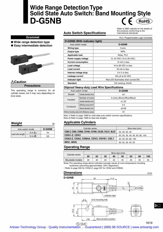
DimensionsD-G5NB
Note 1) Refer to page 1568 for solid state auto switch common specifications.Note 2) Refer to page 1568 for lead wire lengths.
Weight
Auto switch model
3 m (L)
5 m (Z)
(g)
(mm)
Lead wire length
D-G5NB79
125
Applicable Cylinders
Cylinder series
CDM2-Z, CDM2, CDBM2, CDVM3, CDVM5, CDLM2, CDLG1, MLGC
CDG1-Z, CDG1
CDA2-Z, CDA2, CDBA2, CDV3, CDVS1, CDL1
MGC, MGG
Bore size (mm)
20, 25, 32, 40
20, 25, 32, 40, 50, 63, 80, 100
40, 50, 63, 80, 100
20, 25, 32, 40, 50
Auto switch model D-G5NBSheath
Insulator
Conductor
Outside diameter [mm]
Number of cores
Outside diameter [mm]
Effective area [mm2]
Strand diameter [mm]
Minimum bending radius [mm] (Reference values)
ø4
3 cores (Brown/Blue/Black)
ø1.22
0.3
ø0.08
24
Oilproof Heavy-duty Lead Wire Specifications
RoHS
Wide Range Detection TypeSolid State Auto Switch: Band Mounting StyleD-G5NB
Grommet
Wide range detection type Easy intermediate detection
Caution
The operating range is common for all cylinder series, but it may vary depending on bore sizes.
Precautions
D-G5NB (With indicator light)Auto switch model
Wiring type
Output type
Applicable load
Power supply voltage
Current consumption
Load voltage
Load current
Internal voltage drop
Leakage current
Indicator light
Standard
D-G5NB
3-wire
NPN
Relay, PLC
12, 24 VDC (10 to 28 VDC)
12 mA or less
10 to 28 VDC or less
40 mA or less
0.4 V or less
100 µA at 24 VDC
Red LED illuminates when turned ON.
CE marking, RoHS
Auto Switch SpecificationsPLC: Programmable Logic Controller
Refer to SMC website for the details of the products conforming to the international standards.
Operating Range
Cylinder series
Mountable models
Bore size (mm)
20
35
25
40
32
40
40
45
50
45
63
45
80
45
100
50
Note) The operating range above indicates average values at room temperature including hysteresis (assuming approximately ±30% dispersion).
∗ Refer to page 500 for CDA2-Z, page 557 for CDA2 and CDBA2.
11.233
(16)
ø4
14 129.
514.3
SMC
6.5 ø4.5 mounting hole
Indicator light
Most sensitive position
1619
D-D-
Artisan Technology Group - Quality Instrumentation ... Guaranteed | (888) 88-SOURCE | www.artisantg.com

Made to Order Specifications: Solid State Auto Switch
Refer to SMC website for the details of the products conforming to the international standards.
• Eliminates the harnessing work by cable with connector specifications
• Adopts global standardized connector (IEC947-5-2)
• IP67 construction
With Pre-wired Connector1
How to Order
Cable length0.5 m1.0 m3.0 m
SML
Connector model
D M9N S A PC
Note) L is available for the D-P4DW type only.
ABD
Note) Type D is available for the D-P4DW type only.
M8-3 pinM8-4 pinM12-4 pin
Connector Specifications
12
1 2
43
Connector model
Pin arrangement
M8-3 pin M8-4 pin M12-4 pin
1
3
4
3 4
Solid state auto switchStandard part no.
∗ For the applicable auto switch model, refer to the table below.
Applicable Auto Switch
Grommet (In-line)
—
—
—
—
—
—
—
—
—
—
—
—
—
—
—
—
—
—
—
—
—
3.0
Lead wire length (m)
1.00.5Applicable modelFunctionMounting
F79, F7P, J79F7NV, F7PV, F7BVF79W, F7PW, J79W
F7NWV, F7BWVF79FF7BA
F7BAVF7NTP4DW
H7A1, H7A2, H7BG59, G5P, K59
H7NW, H7PW, H7BWG59W, G5PW, K59W
H7NF, G59FH7BA, G5BA
G5NTG5NB
F59, F5P, J59F59W, F5PW, J59W
F59FF5BAF5NT
Electrical entry
Grommet (In-line)Grommet
(Perpendicular)
Grommet (In-line)Grommet
(Perpendicular)
Grommet (In-line)
Grommet (Perpendicular)
—
2-colorindication
With diagnostic output
Water resistant
With timer
Magnetic field resistant
—
2-colorindication
Diagnostic output
Water resistant
With timer
Wide detection
—
2-color indication
Diagnostic output
Water resistant
With timer
Rail mounting style
Band mounting style
Tie-rod mounting style
—
—
—
—
—
—
—
—
—
—
—
—
—
—
—
—
—
—
3.01.00.5
Y59A, Y7P, Y59B
Y69A, Y7PV, Y69B
M9N, M9P, M9B
M9NV, M9PV, M9BV
F8N, F8P, F8B
F6N, F6P, F6B
Y7G, Y7H
F9G, F9H
Y7NW, Y7PW, Y7BW
Y7NWV, Y7PWV, Y7BWV
M9NW, M9PW, M9BW
M9NWV, M9PWV, M9BWV
Y7BA
M9NA, M9PA, M9BA
M9NAV, M9PAV, M9BAV
S791/2, S7P1/2, T791/2
S991/2, S9P1/2, T991/2
S99V1/2, T99V1/2
Grommet (In-line)Grommet
(Perpendicular)
Grommet (In-line)
Grommet (Perpendicular)
Grommet (In-line)
Grommet (In-line)
Grommet (In-line)Grommet
(Perpendicular)
Grommet (In-line)Grommet
(Perpendicular)
Grommet (In-line)
Grommet (Perpendicular)
Grommet (In-line)
Grommet (Perpendicular)
—
—
2-colorindication
Normally closed
Water resistant
Direct mounting style
Rotaryactuator
Lead wire length (m)Applicable modelFunctionMounting
Electrical entry
1626Artisan Technology Group - Quality Instrumentation ... Guaranteed | (888) 88-SOURCE | www.artisantg.com

M8-4 pin
M12-4 pin
M8-3 pin
12
3 4
1 4
3
1 2
43
Connector Pin Arrangement
Sensor type
DC 2-wire type
DC 2-wire, Non-polar type
DC 3-wire type
DC 4-wire type
Brown
—
Brown
Brown
1 pin 2 pin 3 pin 4 pin
Color distinction of lead wire Meaning of contact number
1 pin 2 pin 3 pin 4 pin
Connector SpecificationsConnector model
Pin arrangement
Conformed standard
Impact resistance
Enclosure
Insulation resistance
Withstand voltage
JIS C 4524, JIS C 4525, IEC 947-5-2, NECA 0402
300 m/s2
IP67 (IEC60529 standard)
100 MΩ or more at 500 VDC measured via megohmmeter
1500 VAC 1 minute (between contacts), Leak current 1 mA or less
M8-3 pin M8-4 pin M12-4 pin
—
—
—
Orange
—
Brown
Blue
Blue
Blue
Blue
Black
Black
OUT (+)
—
DC (+)
DC (+)
—
—
—Diagnostic
output
—
OUT (±)
DC (–)
DC (–)
ø14
44
ø10
31.4
Dimensions
Connector model
M8-3 pin 4 pin
M12-4 pin
Sensor section
Sensor section
Weight for Connector Type Connection (Female side) Connector CableAs the parts are not supplied from SMC, refer to the application examples listed in the below.(For detail such as catalog availability, etc., please contact each manufacturer.)
Connector size
M8
M12
SAC-3P
M8-3D
M8-4D
XS3
SAC-4P
VA-4D
XS2
PA5-4I
HR24
CM01-8DP4S
Manufacturer
Phoenix Contact
Corrence Corporation
OMROM Corporation
Phoenix Contact
Corrence Corporation
OMROM Corporation
Azbil Corp.
Hirose Electric Co., Ltd.
DDK Ltd.
4
3
Number of pins Applicable series example
Part no. Connector type
M8-3 pin
M8-4 pin
M12-4 pin
4 g
4 g
About 11 g
Weight
D-APC
D-BPC
D-DPC
OUT (–)
OUT ( )
OUT
OUT
±
1627
With Pre-wired Connector
D-D-
Artisan Technology Group - Quality Instrumentation ... Guaranteed | (888) 88-SOURCE | www.artisantg.com

Made to Order Specifications: Solid State Auto Switch-50: Without Indicator Light (Dark room) Specifications-61: Oilproof Flexible Heavy-duty Cord Specifications
-50Without Indicator Light (for dark room specifications)
Possible to use under the environment which hates a light.
50D
Solid state auto switch model
Lead wire lengthFor lead wire length, refer to page 1568.
Without indicator light(for dark room specifications)
2Symbol
Applicable part no.: General purpose type, solid state auto switch except D-J51
Note) Please consult with SMC for water resistant type, timer equipped type, diagnostic output type, wide range detection type, magnetic field resistant type, heat resistant type.
61D
Dimensions and specifications are common as standard products with the exception of no indicator light.
Oilproof Flexible Heavy-duty Cord Specifications3Symbol
-61
This is the product which uses a heavy-duty cord having flexible characteristics 5 times (SMC comparison) as strong as oilproof heavy-duty cord used in the standard products.
Lead wire lengthFor lead wire length, refer to page 1568.
Oilproof flexible heavy-duty cord specifications
Solid state auto switch part no.
Applicable part no: All the solid state auto switches with the exceptance of D-J51, diagnostic output type, terminal conduit type, connector type, magnetic field resistant type, heat resistant type
Oilproof flexible heavy-duty cord is used for the D-M9 and D-Y7 series (Except D-Y7K) as standard. No need to suffix -61 to the end of part number.
Note)
Specifications are the same as standard products with the exception of lead wire specifications.Lead wire: For D-F8 type············ ø2.7, 0.15 mm2, 3 cores (Brown, Blue, Black), 2 cores (Brown, Blue)For other model nos.··················· ø3.4, 0.15 mm2, 3 cores (Brown, Blue, Black), 2 cores (Brown, Blue)
Dimensions are identical with D-F5 type, G5 type, J59 type, K59 type. Lead wire diameter is changed from ø4 to ø3.4. In other series products, it is common as standard product's specifications.
1628A
Artisan Technology Group - Quality Instrumentation ... Guaranteed | (888) 88-SOURCE | www.artisantg.com

D-A90/A93/A96∗
D-A90V/A93V/A96V∗
Reed Auto SwitchesGeneral Purpose Type,2-Color Indication Type
Band
Rail
Tie-rod
Direct
Grommet
Connector
Terminal conduit
DIN terminal
Grommet
Connector
Grommet
Terminal conduit
DIN terminal
Grommet
1631
1632
1633
1634
1635
1634
1635
1636
1637
1638
1639
1640
1641
1642
Band
Rail
Tie-rod
Grommet
Grommet
Grommet
D-B59W
D-A79W
D-A59W
1643
1644
1645
BandTerminal conduit
Grommet
D-B30/31/35 D-B30J/31J/35J
1649
1630
Heat
re
sist
ant
Rod Grommet
Direct Grommet
D-P79WSE
D-P74
1646
1647
D-C73/C76/C80
D-B53/B54/B64
D-C73C/C80C
D-A33/A34
D-A33A/A34A
D-A44
D-A44A
D-A72/A73/A80
D-A72H/A73H/A76H/A80H
D-A73C/A80C
D-A53/A54/A56/A64/A67
D-A33C/A34C
D-A44C
∗ Auto switches with an asterisk (∗) can be mounted on a band (excluding D-A9V), rail, tie-rod or square groove with an auto switch mounting bracket. Refer to pages 1654, 1658, 1662, 1668 and 1669 for details.
∗∗ This auto switch can be mounted by tie-rod with using auto switch mounting bracket. For details, refer to page 1665.
D-Z73/Z76/Z80∗∗
D-E73A/E76A/E80A
Type Function Electrical entry Auto switch model PageAuto switch
mounting style
Ree
d A
uto
Sw
itch
Gen
eral
pu
rpo
se2-
colo
rind
icatio
nMa
gneti
c fiel
dres
istan
ceReed Switch Variations
1629
D-D-
Artisan Technology Group - Quality Instrumentation ... Guaranteed | (888) 88-SOURCE | www.artisantg.com
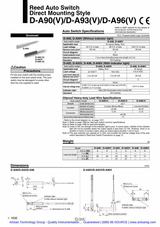
ø2.
72
24.5(22)
2.8 4.5
4
10 ( ): dimensions for D-A96.
D-A90 without indicator light
Indicator light
4
9.1
5.1
ø2.7
10
4.5
Most sensitive position
2
22
6
D-A90V without indicator light
Indicator lightMost sensitive position
Auto switch modelSheath
Insulator
Conductor
Outside diameter [mm]Number of coresOutside diameter [mm]Effective area [mm2]Strand diameter [mm]
Lead wire minimum bending radius [mm] (Reference values)
Grommet D-A90, D-A90V (Without indicator light) Auto switch model Applicable load Load voltage Maximum load current Circuit diagram∗ Contact protection circuit Internal resistance Standard
D-A93, D-A93V, D-A96, D-A96V (With indicator light) Auto switch model Applicable load Load voltage Load current range and Maximum load current (3)
Circuit diagram∗ Contact protection circuit Internal voltage drop
Indicator light Standard
D-A90, D-A90VIC circuit, Relay, PLC
r
None1 Ω or less (Including lead wire length of 3 m)
CE marking
D-A93, D-A93VRelay, PLC
e
24 VDC(4)
5 to 40 mA
NoneD-A93: 2.4 V or less (up to 20 mA)/3 V or less (up to 40 mA)D-A93V: 2.7 V or less
Red LED illuminates when turned ON.CE marking
100 VAC
5 to 20 mA
D-A96, D-A96VIC circuit
4 to 8 VDC
t
20 mA
0.8 V or less
Model D-A906—30—
D-A90V6—30—
D-A936
113047
D-A93V6—3047
D-A968—41—
D-A96V8—41—
Weight
D-A90/D-A93/D-A96 D-A90V/D-A93V/D-A96V
Lead wire length
0.5 m (Nil)1 m (M)3 m (L)5 m (Z)
Slotted set screwM2.5 x 4 L
Slotted set screw
M2.5 x 4 L
∗ Refer to the circuit diagram no. on page 1571. Note 1) Refer to page 1568 for reed auto switch common specifications.Note 2) Refer to page 1568 for lead wire lengths.Note 3) Under 5 mA, the strength of the indicator light is poor. In some cases, visibility of the indicator
light will not be possible where the output signal is less than 2.5 mA. However, there is no problem in terms of contact output, when an output signal exceeds 1 mA or more.
Note 4) The auto switches can operate at 12 VDC, but consider the internal voltage drop of the auto switch described in Reed Auto Switch Precautions on page 12.
Dimensions (mm)
3 cores (Brown/Blue/Black)ø0.910.15
D-A90(V) D-A93(V) D-A96(V)
2 cores (Brown/Blue)ø0.960.18
ø2.7
ø0.0817
Oilproof Heavy-duty Lead Wire Specifications
Refer to SMC website for the details of the products conforming to the international standards.
Fix the auto switch with the existing screw installed on the auto switch body. The auto switch may be damaged if a screw other than the one supplied is used.
PrecautionsCaution
Auto Switch SpecificationsPLC: Programmable Logic Controller
24 V or less50 mA
48 V or less40 mA
100 V or less20 mA
ACDC
ACDC
ACDC
Reed Auto SwitchDirect Mounting StyleD-A90(V)/D-A93(V)/D-A96(V)
D-A90 (V)D-A93VD-A96 (V)
D-A93
1630
(g)
A
Artisan Technology Group - Quality Instrumentation ... Guaranteed | (888) 88-SOURCE | www.artisantg.com

4.3
ø3.
4
6.58
2
9
26
Indicator lightD-C80 without indicator light
SM
C
9.5
811.5
Most sensitive position
ø3.5
Weight
Auto switch model0.5 m (Nil)
3 m (L)5 m (Z)
94676
1050—
946—
D-C73 D-C76 D-C80
(g)
Grommet PLC: Programmable Logic Controller
D-C7 (With indicator light)
Applicable loadLoad voltageMax. load current and range (3)
Circuit diagram∗Contact protection circuitInternal voltage dropIndicator lightStandard
D-C8 (Without indicator light)
Applicable loadLoad voltageMax. load currentCircuit diagram∗Contact protection circuitInternal resistanceStandard
D-C73Relay, PLC
e
24 VDC(4)
5 to 40 mA100 VAC
5 to 20 mA
None2.4 V or less
Red LED illuminates when turned ON.CE marking
D-C76IC circuit
4 to 8 VDC20 mAt
0.8 V or less
D-C80Relay, PLC, IC circuit
r
None1 Ω or less (Including lead wire length of 3 m)
CE marking
Lead wire length
∗ Refer to the circuit diagram no. on page 1571.Note 1) Refer to page 1568 for reed auto switch common specifications.Note 2) Refer to page 1568 for lead wire lengths.Note 3) Under 5 mA, the strength of the indicator light is poor. In some cases, visibility of the
indicator light will not be possible where the output signal is less than 2.5 mA. However, there is no problem in terms of contact output, when an output signal exceeds 1 mA or more.
Note 4) The auto switches can operate at 12 VDC, but consider the internal voltage drop of the auto switch described in Reed Auto Switch Precautions on page 12.
2 cores (Brown/Blue)
Auto switch model D-C73 D-C76 D-C80
2 cores (Brown/Blue)Sheath
Insulator
Conductor
Outside diameter [mm]Number of coresOutside diameter [mm]Effective area [mm2]Strand diameter [mm]
ø3.43 cores (Brown/Blue/Black)
ø1.10.2
ø0.0821
Oilproof Heavy-duty Lead Wire Specifications
Lead wire minimum bending radius [mm] (Reference values)
Refer to SMC website for the details of the products conforming to the international standards.Auto Switch Specifications
Dimensions (mm)
24 V or less50 mA
48 V 40 mA
100 V 20 mA
ACDC
ACDC
ACDC
Reed Auto SwitchBand Mounting StyleD-C73/D-C76/D-C80
Auto switch model
Auto switch model
1631
D-D-
Artisan Technology Group - Quality Instrumentation ... Guaranteed | (888) 88-SOURCE | www.artisantg.com

6.5
ø4
33
13
15 12 SMC
14.3
9.5
15.5
6.5
ø4.5
D-B53PLC
24 VDC(4)
5 to 50 mAe
None2.4 V or less
Red LED illuminates when turned ON.CE marking
D-B54Relay, PLC
24 VDC(4)
5 to 50 mA100 VAC
5 to 25 mA200 VAC
5 to 12.5 mAq
Built-in2.4 V or less (Up to 20 mA)/3.5 V or less (Up to 50 mA)
D-B64Relay, PLC
w
Built-in25 Ω or lessCE marking
Weight
Auto switch model0.5 m (Nil)
3 m (L)5 m (Z)
2278
126
2278126
2278—
D-B53 D-B54 D-B64
(g)
Lead wire length
∗ Refer to the circuit diagram no. on page 1571.Note 1) Refer to page 1568 for reed auto switch common specifications.Note 2) Refer to page 1568 for lead wire lengths.Note 3) Under 5 mA, the strength of the indicator light is poor. In some cases, visibility of the
indicator light will not be possible where the output signal is less than 2.5 mA. However, there is no problem in terms of contact output, when an output signal exceeds 1 mA or more.
Note 4) The auto switches can operate at 12 VDC, but consider the internal voltage drop of the auto switch described in Reed Auto Switch Precautions on page 12.
Auto switch model
Auto switch model
Auto switch model
D-B53/B54/B64Sheath
Insulator
Conductor
Outside diameter [mm]Number of coresOutside diameter [mm]Effective area [mm2]Strand diameter [mm]
ø42 cores (Brown/Blue)
ø1.220.3
ø0.0824
Oilproof Heavy-duty Lead Wire Specifications
Lead wire minimum bending radius [mm] (Reference values)
Grommet
Reed Auto SwitchBand Mounting StyleD-B53/D-B54/D-B64
Refer to SMC website for the details of the products conforming to the international standards.Auto Switch Specifications
PLC: Programmable Logic Controller
D-B5 (With indicator light)
Applicable loadLoad voltageLoad current range (3)
Circuit diagram∗Contact protection circuitInternal voltage drop Indicator lightStandard
D-B6 (Without indicator light)
Applicable loadLoad voltageMax. load current Circuit diagram∗Contact protection circuitInternal resistanceStandard
100 VACMax. 25 mA
200 VACMax. 12.5 mA
ACDC24 V or less
Max. 50 mA
Dimensions (mm)
Indicator lightD-B64 without indicator light
Most sensitiveposition
1632Artisan Technology Group - Quality Instrumentation ... Guaranteed | (888) 88-SOURCE | www.artisantg.com

Weight
Auto switch model
0.5 m (Nil)
3 m (L)
5 m (Z)
14
53
83
14
53
83
D-C73C D-C80C
(g)
Reed Auto SwitchBand Mounting StyleD-C73C/D-C80C
Lead wire length
D-C73C (With indicator light)Auto switch model
Applicable load
Load voltage
Load current range (4)
Circuit diagram∗
Contact protection circuit
Internal voltage drop
Indicator light
Standard
D-C73C
Relay, PLC
24 VDC (5)
5 to 40 mA
e
None
2.4 V or less
Red LED illuminates when turned ON.
CE marking
D-C80C (Without indicator light)Auto switch model
Applicable load
Load voltage
Maximum load current
Circuit diagram∗
Contact protection circuit
Internal resistance
Standard
∗ Refer to the circuit diagram no. on page 1571.Note 1) Refer to page 1568 for reed auto switch common specifications.Note 2) Refer to page 1568 for lead wire lengths.Note 3) Lead wire with connector may be shipped with switch.Note 4) Under 5 mA, the strength of the indicator light is poor. In some cases, visibility of the
indicator light will not be possible where the output signal is less than 2.5 mA. However, there is no problem in terms of contact output, when an output signal exceeds 1 mA or more.
Note 5) The auto switches can operate at 12 VDC, but consider the internal voltage drop of the auto switch described in Reed Auto Switch Precautions on page 12.
Model
D-LC05
D-LC30
D-LC50
Lead wire length
0.5 m
3 m
5 m
Lead wires with a connector indication
Refer to SMC website for the details of the products conforming to the international standards.
Connector PLC: Programmable Logic Controller
Auto Switch Specifications
D-C80C
Relay, PLC
24 V or less
50 mA
r
None
1 Ω or less (Including lead wire length of 3 m)
CE marking
ACDC1. Confirm that the connector is appropriately
tightened. If tightened insufficiently, the waterproof performance will deteriorate.
2. For details, refer to page 1653.
PrecautionsCaution
Dimensions (mm)
Indicator lightD-C80C without indicator light
Most sensitive position
Lead wire with connector
Part No. of Lead Wires with Connectors(Applicable only for connector type)
1633
D-D-
Artisan Technology Group - Quality Instrumentation ... Guaranteed | (888) 88-SOURCE | www.artisantg.com

D-A3 D-A44
Weight
Auto switch model
114116
D-A33116
D-A34 D-A44
(g)
Lead wire None
46
16
25.7
58.7
6.5
349.5
36
34 27.5
Most sensitive position
Terminal conduit: D-A3DIN terminal: D-A4
1. Use cable whose O.D. is within the size in the figure to maintain water resistant performance.
2. After wiring, confirm that tightening gland and all screws are tightened.
PrecautionsCaution
Auto Switch SpecificationsPLC: Programmable Logic Controller
Refer to SMC website for the details of the products conforming to the international standards.
D-A3 (With indicator light) Terminal conduitAuto switch model
Applicable load
Load voltage
Load current range (2)
Circuit diagram∗
Contact protection circuit
Internal voltage drop
Indicator light
Standard
D-A33
PLC
24 VDC (3)
5 to 50 mA
e
None
2.4 V or less
24 VDC (3)
5 to 50 mA
D-A34
Relay, PLC
100 VAC
5 to 25 mA
q
Built-in
2.4 V or less (Up to 20 mA)/3.5 V or less (Up to 50 mA)
200 VAC
5 to 12.5 mA
Red LED illuminates when turned ON.
CE marking
D-A44 (With indicator light) DIN terminalAuto switch model
Applicable load
Load voltage
Load current range
Circuit diagram∗
Contact protection circuit
Internal voltage drop
Indicator light
Standard
24 VDC (3)
5 to 50 mA
D-A44
Relay, PLC
100 VAC
5 to 25 mA
q
Built-in
2.4 V or less (Up to 20 mA)/3.5 V or less (Up to 50 mA)
Red LED illuminates when turned ON.
CE marking
200 VAC
5 to 12.5 mA
∗ Refer to the circuit diagram no. on page 1571.Note 1) Refer to page 1568 for reed auto switch common specifications.Note 2) Under 5 mA, the strength of the indicator light is poor. In some cases, visibility of the
indicator light will not be possible where the output signal is less than 2.5 mA. However, there is no problem in terms of contact output, when an output signal exceeds 1 mA or more.
Note 3) The auto switches can operate at 12 VDC, but consider the internal voltage drop of the auto switch described in Reed Auto Switch Precautions on page 12.
Dimensions (mm)
G 1/2Applicable cable O.D. ø6.8 to ø11.5
Tightening gland
Indicator light Most sensitive position
Applicable cable O.D. ø6.8 to ø9.6G 1/2
Tightening gland
Reed Auto SwitchBand Mounting StyleD-A33/D-A34/D-A44
1634Artisan Technology Group - Quality Instrumentation ... Guaranteed | (888) 88-SOURCE | www.artisantg.com

G 1/2
Tightening gland
Most sensitive position
(Applicable cable O.D. ø6.8 to ø9.6)
Terminal conduit: D-A3 ADIN terminal: D-A44A
1. Use cable whose O.D. is within the size in the figure to maintain water resistant performance.
2. After wiring, confirm that tightening gland and all screws are tightened.
PrecautionsCaution
Auto switch model
None 112 112 110
D-A33A D-A34A D-A44ALead wire
∗ Refer to the circuit diagram no. on page 1571.Note 1) Refer to page 1568 for reed auto switch common specifications.Note 2) Under 5 mA, the strength of the indicator light is poor. In some cases, visibility of the
indicator light will not be possible where the output signal is less than 2.5 mA. However, there is no problem in terms of contact output, when an output signal exceeds 1 mA or more.
Note 3) The auto switches can operate at 12 VDC, but consider the internal voltage drop of the auto switch described in Reed Auto Switch Precautions on page 12.
16
25.7
58.7
6.5
56
3
49.5
36
34 27.5
Most sensitive position
Tightening gland
Auto Switch SpecificationsPLC: Programmable Logic Controller
Refer to SMC website for the details of the products conforming to the international standards.
D-A3A (With indicator light) Terminal conduitAuto switch model
Applicable load
Load voltage
Load current range (2)
Circuit diagram∗
Contact protection circuit
Internal voltage drop
Indicator light
Standard
D-A44A (With indicator light) DIN terminalAuto switch part model
Applicable load
Load voltage
Load current range
Circuit diagram∗
Contact protection circuit
Internal voltage drop
Indicator lightStandard
D-A33APLC
24 VDC (3)
5 to 50 mA
e
None
2.4 V or less
D-A34ARelay, PLC
100 VAC
5 to 25 mA
q
Built-in
2.4 V or less (Up to 20 mA)/3.5 V or less (Up to 50 mA)
200 VAC
5 to 12.5 mA
24 VDC (3)
5 to 50 mA
24 VDC (3)
5 to 50 mA
200 VAC
5 to 12.5 mA
D-A44ARelay, PLC
100 VAC
5 to 25 mA
q
Built-in
2.4 V or less (Up to 20 mA)/3.5 V or less (Up to 50 mA)
Red LED illuminates when turned ON.
CE marking
Red LED illuminates when turned ON.
CE marking
DimensionsD-A3A D-A44
(mm)
Weight (g)
G 1/2(Applicable cable O.D.
ø6.8 to ø11.5)
Reed Auto SwitchBand Mounting StyleD-A33A/D-A34A/D-A44A
1635
D-D-
Artisan Technology Group - Quality Instrumentation ... Guaranteed | (888) 88-SOURCE | www.artisantg.com

( ) values for D-A72
8
15 (
14)
7 (6
)4
23 (22)
Indicator light
D-A80 without indicator light
ø3.2
9 (8.5)
ø3.4
Most sensitive position
6 (6
.2)
3
11.5
(11
.7)
Auto switch model
0.5 m (Nil)
3 m (L)
5 m (Z)
10
47
—
10
47
77
10
47
—
D-A72 D-A73 D-A80
Lead wire length
D-A7 (With indicator light)Auto switch model
Applicable loadLoad voltageLoad current range (3)
Circuit diagram∗Contact protection circuitInternal voltage dropIndicator lightStandard
24 VDC (4)
5 to 40 mAe
None2.4 V or less
Red LED illuminates when turned ON.CE marking
100 VAC5 to 20 mA
D-A72Relay, PLC
200 VAC5 to 10 mA
D-A73Relay, PLC
D-A80Relay, IC circuit, PLC
40 mAr
None1 Ω or less (Including lead wire length of 3 m)
CE marking
D-A8 (Without indicator light)Auto switch model
Applicable loadLoad voltageMaximum load currentCircuit diagram∗Contact protection circuitInternal resistanceStandard
50 mA 20 mA
∗ Refer to the circuit diagram no. on page 1571.Note 1) Refer to page 1568 for reed auto switch common specifications.Note 2) Refer to page 1568 for lead wire lengths.Note 3) Under 5 mA, the strength of the indicator light is poor. In some cases, visibility of the
indicator light will not be possible where the output signal is less than 2.5 mA. However, there is no problem in terms of contact output, when an output signal exceeds 1 mA or more.
Note 4) The auto switches can operate at 12 VDC, but consider the internal voltage drop of the auto switch described in Reed Auto Switch Precautions on page 12.
Auto switch model D-A72 D-A73 D-A80Sheath
Insulator
Conductor
Outside diameter [mm]Number of coresOutside diameter [mm]Effective area [mm2]Strand diameter [mm]
ø3.42 cores (Brown/Blue)
ø1.10.2
ø0.0821
Oilproof Heavy-duty Lead Wire Specifications
Lead wire minimum bending radius [mm] (Reference values)
Auto Switch SpecificationsPLC: Programmable Logic Controller
Refer to SMC website for the details of the products conforming to the international standards.
GrommetElectrical entry: Perpendicular
Dimensions (mm)
Weight (g)
24 V or lessACDC 48 V AC
DC 100 V ACDC
Reed Auto SwitchRail Mounting StyleD-A72/D-A73/D-A80
1636Artisan Technology Group - Quality Instrumentation ... Guaranteed | (888) 88-SOURCE | www.artisantg.com

2
ø3.
4
22
8.5
15
74
8
ø3.2
SMC
6.2
3.3
10.2
Auto switch model0.5 m (Nil)
3 m (L)5 m (Z)
1047—
1047—
1152—
104777
D-A72H D-A73H D-A76H D-A80H
Lead wire length
D-A7H (With indicator light)Auto switch model
Applicable loadLoad voltageMax. load current/Load current range(3)
Circuit diagram∗Contact protection circuitInternal voltage dropIndicator lightStandard
100 VAC5 to 20 mA
D-A72HRelay, PLC
200 VAC5 to 10 mA
D-A73HRelay, PLC
None
Red LED illuminates when turned ON.CE marking
e
D-A80HRelay, IC circuit, PLC
40 mAr
None1 Ω or less (Including lead wire length of 3 m)
CE marking
D-A80H (Without indicator light)Auto switch model
Applicable loadLoad voltageMaximum load currentCircuit diagram∗Contact protection circuitInternal resistanceStandard
20mA50 mA
∗ Refer to the circuit diagram no. on page 1571.Note 1) Refer to page 1568 for reed auto switch common specifications.Note 2) Refer to page 1568 for lead wire lengths.Note 3) Under 5 mA, the strength of the indicator light is poor. In some cases, visibility of the
indicator light will not be possible where the output signal is less than 2.5 mA. However, there is no problem in terms of contact output, when an output signal exceeds 1 mA or more.
Note 4) The auto switches can operate at 12 VDC, but consider the internal voltage drop of the auto switch described in Reed Auto Switch Precautions on page 12.
2 cores (Brown/Blue)
Auto switch model
Lead wire minimum bending radius [mm] (Reference values)
D-A72H/A73H D-A76H D-A80H
2 cores (Brown/Blue)Sheath
Insulator
Conductor
Outside diameter [mm]Number of coresOutside diameter [mm]Effective area [mm2]Strand diameter [mm]
ø3.43 cores (Brown/Blue/Black)
ø1.10.2
ø0.0821
Oilproof Heavy-duty Lead Wire Specifications
24 VDC (4)
5 to 40 mAe
2.4 V or less
D-A76HIC circuit
4 to 8 VDC20 mAt
0.8 V or less
GrommetElectrical entry: In-line
Auto Switch SpecificationsPLC: Programmable Logic Controller
Refer to SMC website for the details of the products conforming to the international standards.
24 V or lessACDC 48 V AC
DC 100 V ACDC
Weight (g)
DimensionsD-A7H, D-A80H
(mm)
Indicator lightD-A80H without indicator light
Most sensitive position
Reed Auto SwitchRail Mounting StyleD-A7H/D-A80H
1637
D-D-
Artisan Technology Group - Quality Instrumentation ... Guaranteed | (888) 88-SOURCE | www.artisantg.com

Auto switch model
0.5 m (Nil)
3 m (L)
5 m (Z)
12
54
84
12
54
84
D-A73C D-A80C
Lead wire length
∗ Refer to the circuit diagram no. on page 1571.Note 1) Refer to page 1568 for reed auto switch common specifications.Note 2) Refer to page 1568 for lead wire lengths.Note 3) Lead wire with connector may be shipped with the auto switch.Note 4) Under 5 mA, the strength of the indicator light is poor. In some cases, visibility of the
indicator light will not be possible where the output signal is less than 2.5 mA. However, there is no problem in terms of contact output, when an output signal exceeds 1 mA or more.
Note 5) The auto switches can operate at 12 VDC, but consider the internal voltage drop of the auto switch described in Reed Auto Switch Precautions on page 12.
Model
D-LC05
D-LC30
D-LC50
Lead wire length
0.5 m
3 m
5 m
Part No. of Lead Wires with Connectors(Applicable only for connector type)
Connector
1. Confirm that the connector is appropriately tightened. If tightened insufficiently, the waterproof performance will deteriorate.
2. Refer to page 1653 for the details.
PrecautionsCaution
Auto Switch SpecificationsPLC: Programmable Logic Controller
Refer to SMC website for the details of the products conforming to the international standards.
D-A73C (With indicator light)D-A73C
Relay, PLC
24 VDC (5)
5 to 40 mA
e
None
2.4 V or less
Red LED illuminates when turned ON.
CE marking
D-A80C
Relay, IC circuit, PLC
50 mA
r
None
1 Ω or less (Including lead wire length of 3 m)
CE marking
D-A80C (Without indicator light)
Auto switch model
Applicable load
Load voltage
Load current range (4)
Circuit diagram∗
Contact protection circuit
Internal voltage drop
Indicator light
Standard
Auto switch model
Applicable load
Load voltage
Maximum load current
Circuit diagram∗
Contact protection circuit
Internal resistance
Standard
24 V ACDC
Dimensions (mm)
Weight (g)
Indicator lightD-A80C without indicator light
Most sensitive position
Lead wire with connector
Lead wires with a connector indication
Reed Auto SwitchRail Mounting StyleD-A73C/D-A80C
1638Artisan Technology Group - Quality Instrumentation ... Guaranteed | (888) 88-SOURCE | www.artisantg.com

1233
22
512
4.5
6 14
6
D-A64/A67 without indicator light
Indicator light
ø4
16 Most sensitive position
1611
Auto switch model0.5 m (Nil)
3 m (L)5 m (Z)
244896
2448—
2448—
D-A53 D-A54 D-A56 D-A64 D-A67
Lead wire length
D-A5 (With indicator light)Auto switch model
Applicable loadLoad voltageMaximum load (3)
current and rangeCircuit diagram∗Contact protection circuitInternal voltage dropIndicator lightStandard
D-A53
24 VDC (4)
5 to 50 mA
D-A54
200 VAC
5 to 12.5 mA
D-A56PLC
24 VDC (4)
5 to 50 mA
e
None2.4 V or less
Relay, PLC100 VAC
5 to 25 mA
q
Built-in2.4 V or less (Up to 20 mA)/3.5 V or less (Up to 50 mA)
IC circuit4 to 8 VDC
20 mA
t
None0.8 V or less
D-A6 (Without indicator light)Auto switch model
Applicable loadLoad voltageMaximum load currentCircuit diagram∗Contact protection circuit
Internal resistance
D-A67PLC/IC circuitMax. 24 VDC
30 mAr
None1 Ω or less (Including
lead wire length of 3 m)
D-A64Relay, PLC100 VAC25 mAw
Built-in
25 Ω or less
Red LED illuminates when turned ON.CE marking
Standard CE marking
∗ Refer to the circuit diagram no. on page 1571.Note 1) Refer to page 1568 for reed auto switch common specifications.Note 2) Refer to page 1568 for lead wire lengths.Note 3) Under 5 mA, the strength of the indicator light is poor. In some cases, visibility of the indicator light will
not be possible where the output signal is less than 2.5 mA. However, there is no problem in terms of contact output, when an output signal exceeds 1 mA or more.
Note 4) The auto switches can operate at 12 VDC, but consider the internal voltage drop of the auto switch described in Reed Auto Switch Precautions on page 12.
2 cores (Brown/Blue)
0.3
Auto switch model
Lead wire minimum bending radius [mm] (Reference values)
D-A53/A54 D-A56 D-A64/A67Sheath
Insulator
Conductor
Outside diameter [mm]Number of cores
Outside diameter [mm]Effective area [mm2]
Strand diameter [mm]
ø43 cores (Brown/Blue/Black)
ø1.220.2
ø0.0824
2 cores (Brown/Blue)
0.3
Oilproof Heavy-duty Lead Wire Specifications
Grommet PLC: Programmable Logic Controller
Refer to SMC website for the details of the products conforming to the international standards.Auto Switch Specifications
200 VAC12.5 mA50 mA
24 V or lessACDC
Dimensions (mm)
Weight (g)
Reed Auto SwitchTie-rod Mounting StyleD-A5/D-A6
1639
D-D-
Artisan Technology Group - Quality Instrumentation ... Guaranteed | (888) 88-SOURCE | www.artisantg.com

D-A33C D-A34C
200 VAC 5 to 12.5 mA
24 VDC (3)
5 to 50 mA
24 VDC (3)
5 to 50 mA200 VAC
5 to 12.5 mA
D-A44C
PLC 24 VDC (3)
5 to 50 mAe
None2.4 V or less
Relay, PLC 100 VAC
5 to 25 mAq
Built-in2.4 V or less (Up to 20 mA)/3.5 V or less (Up to 50 mA)
Relay, PLC100 VAC
5 to 25 mAq
Built-in2.4 V or less (Up to 20 mA)/3.5 V or less (Up to 50 mA)
Red LED illuminates when turned ON.CE marking
D-A33C-4, A34C-4D-A33C-5, A34C-5D-A33C-6, A34C-6D-A33C-8, A34C-8D-A33C-10, A34C-10
Applicable bore size(mm) Weight
40506380
100
162166184210232
Auto switch model
D-A44C-4D-A44C-5D-A44C-6D-A44C-8D-A44C-10
Applicable bore size(mm) Weight
40506380100
160164182208230
Auto switch model
Red LED illuminates when turned ON.CE marking
∗ Refer to the circuit diagram no. on page 1571.Note 1) Refer to page 1568 for reed auto switch common specifications.Note 2) Under 5 mA, the strength of the indicator light is poor. In some cases, visibility of the indicator
light will not be possible where the output signal is less than 2.5 mA. However, there is no problem in terms of contact output, when an output signal exceeds 1 mA or more.
Note 3) The auto switches can operate at 12 VDC, but consider the internal voltage drop of the auto switch described in Reed Auto Switch Precautions on page 12.
Weight (g)
Auto Switch SpecificationsPLC: Programmable Logic Controller
Refer to SMC website for the details of the products conforming to the international standards.
Terminal conduit:D-A3CDIN terminal: D-A44C
1. Use cable whose O.D. is within the size in the figure to maintain water resistant performance.
2. After wiring, confirm that tightening gland and all screws are tightened.
PrecautionsCaution
D-A3C (With indicator light) Terminal conduitAuto switch model
Applicable loadLoad voltageLoad current range (2)
Circuit diagram∗Contact protection circuitInternal voltage drop Indicator lightStandardD-A44C (With indicator light) DIN terminal
Auto switch model Applicable loadLoad voltageLoad current range (2)
Circuit diagram∗Contact protection circuitInternal voltage drop Indicator lightStandard
Dimensions (mm)
D-A3C-4, D-A44C-4D-A3C-5, D-A44C-5D-A3C-6, D-A44C-6D-A3C-8, D-A44C-8D-A3C-10, D-A44C-10
Applicable boresize (mm)
40506380
100
C
4452647892
HW
697791
107 121
H
58 (67.5)59 (68.5)61.5 (71)65 (74.5)68 (77.5)
H'
50.5 (60)51.5 (61)53 (62.5)54.5 (64)57.5 (67)
T
7.5 8.5 10.512.515.5
T'
6.5 6.5 7.5 9.5 9.5
M5 x 0.8 x 16
M5 x 0.8 x 20
M5 x 0.8 x 25
∗ ( ): Denotes the values of D-A44C
ZAuto switch model
DimensionsD-A3C D-A44C
(mm)
(Applicable cable O.D. ø6.8 to ø9.6)
(Applicable cable O.D. ø6.8 to ø11.5)
2 x M5 x 0.8 x 12Hexagon socket head cap bolt
Tightening gland2 x M5 x 0.8 x 12
Hexagon socket head cap boltTightening gland
Hexagon sockethead cap bolt
G 1/2 G 1/2
Indicator lightMost sensitive position
Hexagon sockethead cap bolt
4 x Z4 x Z
Most sensitive position
Reed Auto SwitchTie-rod Mounting StyleD-A33C/D-A34C/D-A44C
1640Artisan Technology Group - Quality Instrumentation ... Guaranteed | (888) 88-SOURCE | www.artisantg.com

12.5 ø2.
7
5.5
30.52.3
6.2
1.5
2.5
6.2
27.6
∗ Refer to the circuit diagram no. on page 1571.Note 1) Refer to page 1568 for reed auto switch common specifications.Note 2) Refer to page 1568 for lead wire lengths.Note 3) Under 5 mA, the strength of the indicator light is poor. In some cases, visibility of the
indicator light will not be possible where the output signal is less than 2.5 mA. However, there is no problem in terms of contact output, when an output signal exceeds 1 mA or more.
Note 4) The auto switches can operate at 12 VDC, but consider the internal voltage drop of the auto switch described in Reed Auto Switch Precautions on page 12.
Auto switch model
Lead wire minimum bending radius [mm] (Reference values)
D-Z73 D-Z76 D-Z80ø2.7
2 cores (Brown/Blue)
0.18
17
Sheath
Insulator
Conductor
Outside diameter [mm]Number of coresOutside diameter [mm]Effective area [mm2]Strand diameter [mm]
ø3.43 cores (Brown/Blue/Black)
ø1.10.2
ø0.0821
ø2.72 cores (Brown/Blue)
0.18
17
Oilproof Heavy-duty Lead Wire Specifications
Auto switch model0.5 m (Nil)
3 m (L)5 m (Z)
73150
1055—
D-Z73 D-Z76 D-Z80
Lead wire length
D-Z7 (With indicator light)Auto switch model
Applicable loadLoad voltageMax. load current and load current range(3)
Circuit diagram∗Contact protection circuitInternal voltage dropIndicator lightStandard
D-Z73
24 VDC (4)
5 to 40 mA100 VAC
5 to 20 mA
None
Red LED illuminates when turned ON.CE marking
D-Z76
D-Z80
Relay, PLC
e
2.4 V or less (Up to 20 mA)/3 V or less (Up to 40 mA)
IC circuit4 to 8 VDC
20 mAt
0.8 V or less
Relay, PLC, IC circuit
40 mAr
None1 Ω or less (Including 3 m lead wire)
CE marking
D-Z8 (Without indicator light)Auto switch model
Applicable load
Load voltage
Maximum load currentCircuit diagram∗Contact protection circuitInternal resistanceStandard
50 mA 20 mA
24 V or lessACDC 100 VAC
DC48 VACDC
731—
GrommetAuto Switch Specifications
PLC: Programmable Logic Controller
Refer to SMC website for the details of the products conforming to the international standards.
Weight (g)
D-Z73, Z80 D-Z76
Dimensions (mm)
Slotted set screw
Slotted set screw
Indicator light
D-Z80 without indicator light
Indicator light
Most sensitive position
Most sensitive position
M2.5 x 4L
M2.5 x 4L
12.5
5.7
ø3.
4
Reed Auto SwitchDirect Mounting StyleD-Z73/D-Z76/D-Z80
1641
D-D-
Artisan Technology Group - Quality Instrumentation ... Guaranteed | (888) 88-SOURCE | www.artisantg.com

6.4
0.50.5 6
2.4
88
2.7
8.5
ø3.
4
6 3
12.5
0.5
22
D-E73ASMC
Dimensions (mm)
Indicator light
D-E80A without indicator light
Most sensitive position
Reed Auto SwitchDirect Mounting StyleD-E73A/D-E76A/D-E80A
Auto switch model0.5 m (Nil)
3 m (L)1047
1155
1047
D-E73A D-E76A D-E80A
Lead wire length
D-E7A (With indicator light)Auto switch model
Applicable loadLoad voltageMax. load current and load current range(3)
Circuit diagram∗Contact protection circuitInternal voltage dropIndicator lightStandard
D-E73A
24 VDC (4)
5 to 40 mA100 VAC
5 to 20 mA
None
Red LED illuminates when turned ON.CE marking
D-E76A
D-E80A
Relay, PLC
e
2.4 V or less
IC circuit4 to 8 VDC
20 mAt
0.8 V or less
Relay, PLC, IC circuit
40 mAr
None1 Ω or less (Including lead wire length of 3 m)
CE marking
D-E80A (Without indicator light)Auto switch model
Applicable loadLoad voltageMaximum load currentCircuit diagram∗Contact protection circuitInternal resistanceStandard
50 mA 20 mA
∗ Refer to the circuit diagram no. on page 1571.Note 1) Refer to page 1568 for reed auto switch common specifications.Note 2) Refer to page 1568 for lead wire lengths.Note 3) Under 5 mA, the strength of the indicator light is poor. In some cases, visibility of the
indicator light will not be possible where the output signal is less than 2.5 mA. However, there is no problem in terms of contact output, when an output signal exceeds 1 mA or more.
Note 4) The auto switches can operate at 12 VDC, but consider the internal voltage drop of the auto switch described in Reed Auto Switch Precautions on page 12.
2 cores (Brown/Blue)
Auto switch model
Lead wire minimum bending radius [mm] (Reference values)
D-E73A D-E76A D-E80A
2 cores (Brown/Blue)Sheath
Insulator
Conductor
Outside diameter [mm]Number of coresOutside diameter [mm]Effective area [mm2]Strand diameter [mm]
ø3.43 cores (Brown/Blue/Black)
ø1.10.2
ø0.0821
Oilproof Heavy-duty Lead Wire Specifications
Weight (g)
GrommetAuto Switch Specifications
PLC: Programmable Logic Controller
Refer to SMC website for the details of the products conforming to the international standards.
24 V or lessACDC 100 VAC
DC48 VACDC
1642Artisan Technology Group - Quality Instrumentation ... Guaranteed | (888) 88-SOURCE | www.artisantg.com

6.5
ø4
33
13
15 12
0.5
14.3
9.5
6.5
12.6ø4.5
∗ Refer to the circuit diagram no. on page 1571.Note 1) Refer to page 1568 for reed auto switch common specifications.Note 2) Refer to page 1568 for lead wire lengths.Note 3) Under 5 mA, the strength of the indicator light is poor. In some cases, visibility of the
indicator light will not be possible where the output signal is less than 2.5 mA. However, there is no problem in terms of contact output, when an output signal exceeds 1 mA or more.
Auto switch model
Lead wire minimum bending radius [mm] (Reference values)
D-B59WSheath
Insulator
Conductor
Outside diameter [mm]
Number of cores
Outside diameter [mm]
Effective area [mm2]
Strand diameter [mm]
ø4
2 cores (Brown/Blue)
ø1.22
0.3
ø0.08
24
Oilproof Heavy-duty Lead Wire Specifications
Auto switch model
0.5 m (Nil)
3 m (L)
20
76
D-B59W
Lead wire length
Grommet
The proper operating range can be determined by the color of the light.(Red → Green ← Red)
Auto Switch SpecificationsPLC: Programmable Logic Controller
Refer to SMC website for the details of the products conforming to the international standards.
D-B59W (With indicator light)Auto switch model
Applicable load
Load voltage
Load current range(3)
Circuit diagram∗
Contact protection circuit
Internal voltage drop
Indicator light
D-B59W
Relay, PLC
24 VDC
5 to 40 mA
y
Built-in
4 V or less
Standard CE marking
Operating range .......... Red LED illuminates.Proper operating range .......... Green LED illuminates.
Dimensions (mm)
Indicator light
Most sensitive position
Weight (g)
2-Color Indication Type Reed Auto SwitchBand Mounting StyleD-B59W
1643
D-D-
Artisan Technology Group - Quality Instrumentation ... Guaranteed | (888) 88-SOURCE | www.artisantg.com

1.8
36.
2
14
ø3.4
11.5 Most sensitive position
15
74
8
23.5
Indicator light
ø3.2
Auto switch model
0.5 m (Nil)
3 m (L)
11
53
D-A79W
Lead wire length
D-A79W (With indicator light)Auto switch model
Applicable load
Load voltage
Load current range (3)
Circuit diagram∗
Contact protection circuit
Internal voltage drop
Indicator light
D-A79W
Relay, PLC
24 VDC
5 to 40 mA
u
None
4 V or less
Standard CE marking
∗ Refer to the circuit diagram no. on page 1571.Note 1) Refer to page 1568 for reed auto switch common specifications.Note 2) Refer to page 1568 for lead wire lengths.Note 3) Under 5 mA, the strength of the indicator light is poor. In some cases, visibility of the
indicator light will not be possible where the output signal is less than 2.5 mA. However, there is no problem in terms of contact output, when an output signal exceeds 1 mA or more.
Auto switch model
Lead wire minimum bending radius [mm] (Reference values)
D-A79WSheath
Insulator
Conductor
ø3.4
2 cores (Brown/Blue)
ø1.1
0.2
ø0.08
21
Oilproof Heavy-duty Lead Wire Specifications
Outside diameter [mm]
Number of cores
Outside diameter [mm]
Effective area [mm2]
Strand diameter [mm]
2-Color Indication Type Reed Auto SwitchRail Mounting StyleD-A79W
Grommet
The proper operating range can be determined by the color of the light.(Red → Green ← Red)
PLC: Programmable Logic Controller
Refer to SMC website for the details of the products conforming to the international standards.Auto Switch Specifications
Operating range .......... Red LED illuminates.Proper operating range .......... Green LED illuminates.
Dimensions (mm)
Weight (g)
1644Artisan Technology Group - Quality Instrumentation ... Guaranteed | (888) 88-SOURCE | www.artisantg.com

11
160.
5
Most sensitive position12
ø4
1233
23
134.
9
146
7
Indicator light
ø4.5
Auto switch model
0.5 m (Nil)
3 m (L)
25
80
D-A59W
Lead wire length
D-A59W (With indicator light)Auto switch model
Applicable load
Load voltage
Load current range(3)
Circuit diagram∗
Contact protection circuit
Internal voltage drop
Indicator light
Standard
D-A59W
Relay, PLC
24 VDC
5 to 40 mA
y
Built-in
4 V or less
CE marking
∗ Refer to the circuit diagram no. on page 1571.Note 1) Refer to page 1568 for reed auto switch common specifications.Note 2) Refer to page 1568 for lead wire lengths.Note 3) Under 5 mA, the strength of the indicator light is poor. In some cases, visibility of the
indicator light will not be possible where the output signal is less than 2.5 mA. However, there is no problem in terms of contact output, when an output signal exceeds 1 mA or more.
Auto switch model
Lead wire minimum bending radius [mm] (Reference values)
D-A59WSheath
Insulator
Conductor
ø4
2 cores (Brown/Blue)
ø1.22
0.3
ø0.08
24
Oilproof Heavy-duty Lead Wire Specifications
Outside diameter [mm]
Number of cores
Outside diameter [mm]
Effective area [mm2]
Strand diameter [mm]
2-Color Indication Type Reed Auto SwitchTie-rod Mounting StyleD-A59W
Grommet
The proper operating range can be determined by the color of the light.(Red → Green ← Red)
PLC: Programmable Logic Controller
Refer to SMC website for the details of the products conforming to the international standards.Auto Switch Specifications
Operating range .......... Red LED illuminates.Proper operating range .......... Green LED illuminates.
Dimensions (mm)
Weight (g)
1645
D-D-
Artisan Technology Group - Quality Instrumentation ... Guaranteed | (888) 88-SOURCE | www.artisantg.com

∗ Refer to the circuit diagram no. on page 1571.Note 1) Refer to page 1568 for reed auto switch common specifications.
Auto switch modelD-P79WSE
100
Auto switch model
Lead wire minimum bending radius [mm] (Reference values)
D-P79WSESheath
Insulator
Conductor
Outside diameter [mm]
Number of cores
Outside diameter [mm]
Effective area [mm2]
Strand diameter [mm]
ø6
2 cores
ø2.3
0.5
ø0.08
48
Oilproof Heavy-duty Lead Wire Specifications
Grommet
The proper operating range can be determined by the color of the light.(Red → Green ← Red)
PrecautionsCaution
Cylinder with a strong integrated magnet must be used.
Auto Switch SpecificationsPLC: Programmable Logic Controller
Refer to SMC website for the details of the products conforming to the international standards.
Auto switch model
Applicable load
Load voltage
Load current range
Circuit diagram∗
Contact protection circuit
Internal voltage drop
Indicator light
Standard
PLC
24 VDC
8 to 20 mA
y
Built-in
6 V or less
CE marking
D-P79WSE
Dimensions (mm)
44
ø6
16
14.6
300532
5
4
20
SM
C
MADE
IN JA
PAN
DC
24V
D-P7
9W
D-P79WSE
ø14
Most sensitive position
Indicator light
Heat shrink tube Note)
Note) D-P79WSE = “SE 1 4-”
2 x ø3.4 through
2 x 2 x ø6
Counterbore depth 2.4
Connector size M12
Soft resin mold surface(Mounting surface for the switch mounting bracket side)
CautionPlease be careful of the mounting direction.The soft resin mold surface must be directed to the switch mounting bracket side.
Operating range .......... Red LED illuminates.Proper operating range .......... Green LED illuminates.
Weight (g)
Magnetic Field Resistant 2-Color Indication TypeReed Auto SwitchD-P79WSE(Electrical Entry: Pre-wired connector)
1646Artisan Technology Group - Quality Instrumentation ... Guaranteed | (888) 88-SOURCE | www.artisantg.com

Auto switch model
Electrical entry
Application
Load voltage
Max. load voltage/Load current range
Circuit diagram∗
Contact protection circuit
Internal voltage drop (internal resistance)
Leakage current
Indicator light
Standard
Grommet
Relay, PLC
q
Built-in
2.4 V or less
0
Red LED illuminates when turned ON.
D-P74L/Z (With indicator light)D-P74
CE marking
Auto switch model
3 m (L)
5 m (Z)
189
320
D-P74
Lead wire length
∗ Refer to the circuit diagram no. on page 1571.Note 1) Refer to page 1568 for reed auto switch common specifications.Note 2) Refer to page 1568 for lead wire lengths.Note 3) Under 5 mA, the strength of the indicator light is poor. In some cases, visibility of the
indicator light will not be possible where the output signal is less than 2.5 mA. However, there is no problem in terms of contact output, when an output signal exceeds 1 mA or more.
Auto switch model
Lead wire minimum bending radius [mm] (Reference values)
D-P74Sheath
Insulator
Conductor
Outside diameter [mm]
Number of cores
Outside diameter [mm]
Effective area [mm2]
Strand diameter [mm]
ø6.8
2 cores (White/Black)
ø1.1
0.75
ø0.18
48
Oilproof Heavy-duty Lead Wire Specifications
Weight (g)
Grommet
PrecautionsCaution
Cylinder with a strong integrated magnet must be used.
Auto Switch SpecificationsPLC: Programmable Logic Controller
Refer to SMC website for the details of the products conforming to the international standards.
Dimensions (mm)
ø6.
8
13.6
532
16
20
4
5
SM
C
Indicator light
Most sensitive position
24 VDC
5 to 40 mA
100 VAC
5 to 20 mA
2 x 2 x ø6
Counterbore depth 2.4
2 x ø3.4 through
Magnetic Field Resistant Reed Auto SwitchD-P74
1647
D-D-
A
Artisan Technology Group - Quality Instrumentation ... Guaranteed | (888) 88-SOURCE | www.artisantg.com

Auto switch model
Electrical entry
Application
Load voltage
Max. load current/Load current range
Circuit diagram∗
Contact protection circuit
Internal voltage drop (internal resistance)
Leakage current
Operating time
Indicator light
Standard
Grommet
Relay, PLC
24 VDC
5 to 20 mA
q
Built-in
2 V or less
0
1.2 ms
Red LED illuminates when turned ON.
CE marking
D-P74-376 (With indicator light)D-P74-376
Auto switch model60
D-P74-376
∗ Refer to the circuit diagram no. on page 1571.Note 1) Refer to page 1568 for reed auto switch common specifications.Note 2) Under 5 mA, the strength of the indicator light is poor. In some cases, visibility of the
indicator light will not be possible where the output signal is less than 2.5 mA. However, there is no problem in terms of contact output, when an output signal exceeds 1 mA or more.
Auto switch model
Lead wire minimum bending radius [mm] (Reference values)
D-P74Sheath
Insulator
Conductor
Outside diameter [mm]
Number of cores
Outside diameter [mm]
Effective area [mm2]
Strand diameter [mm]
ø6
2 cores
ø1.1
0.75
ø0.18
48
Oilproof Heavy-duty Lead Wire Specifications
Weight (g)
PLC: Programmable Logic Controller
Refer to SMC website for the details of the products conforming to the international standards.Auto Switch Specifications
Grommet
PrecautionsCaution
Cylinder with a strong integrated magnet must be used.
Dimensions (mm)
500
ø6
20
4
44.5
16
532
5
13.6
SM
C
ø14
Most sensitive position
Indicator light
Counterbore depth 2.4
2 x 2 x ø6
2 x ø3.4 through
Connector size M12
Magnetic Field Resistant Reed Auto SwitchD-P74-376
1648Artisan Technology Group - Quality Instrumentation ... Guaranteed | (888) 88-SOURCE | www.artisantg.com

Auto Switch Internal Circuit
D-B30
Heat Resistant Reed Auto SwitchD-B30(J)/31(J)/35(J)
D-B31
D-B35
Auto switch model
None
0.5 m (Nil)
3 m (L)
5 m (Z)
190
—
—
—
D-B30—
250
268
462
D-B30J190
—
—
—
D-B31—
250
268
462
D-B31J190
—
—
—
D-B35—
250
268
462
D-B35J
Lead wirelength
Can be used outdoors or under high temperature (Max. 120°C).Wide operating range (double that of other SMC products) enables stable position detection.
High temperature environment such as places around ignited gas outlet or furnace
Outdoor plants and environment with high temperature and humidity
Environment for steam cleaning or high temperature sterilization
Applications requiring wide operating range such as clamping of elastic work piecesUse of metal case and heat resistant materials.The construction prevents influence of external environment by sealing the auto switch internal parts to improve heat resistance.The wide operating range allows easy position setting and reduces influence of the work piece position changes.
Auto switch model D-B30J D-B31J D-B35JSheath
Insulator
Conductor
Outside diameter [mm]
Number of cores
Outside diameter [mm]
Effective area [mm2]
Strand diameter [mm]
ø6
2 cores (Brown/Blue)
ø2.3
0.5
ø0.08
48 (Room temperature)
Oilproof Heavy-duty Lead Wire Specifications
Lead wire minimum bending radius [mm] (Reference values)
Weight (g)
Auto Switch SpecificationsPLC: Programmable Logic Controller
Refer to SMC website for the details of the products conforming to the international standards.
Auto switch model
Electrical entry
Operating voltage
Operating current range
Internal voltage drop
Indicator light
Applicable load
Shock resistance
Leakage current
Lead wire
Enclosure
Withstand voltage
Insulation resistance
Operating temperature range
Standard
D-B30 D-B30J D-B31 D-B31J D-B35 D-B35J
24 VDC / 100 VAC
5 to 30 mADC / 5 to 20 mAAC
2.5 V or less
Without indicator light
0.1 mA or less
100 VAC
5 to 20 mAAC
2.5 V or less
Neon bulb lights up when OFF
PLC (Programmable Logic Controller)
300 m/s2
1 mA or less
24 VDC
5 to 30 mADC
2.0 V or less
Red LED lights up when OFF
1 mA or less
Terminal
conduitGrommet
Terminal
conduitGrommet
Terminal
conduitGrommet
Terminal conduit : IEC60529 IP64
Grommet : IEC60529 IP67
1500 VAC for 1 minute (between case and terminals or lead wires)
50 MΩ or larger between case (ground) and lead wires (terminals)
–10C to 120C
CE marking
— 0.5 m — 0.5 m — 0.5 m
Lead wire lengthIn case of the grommet type (J type), the lead wire length is 0.5 m.(No lead wire is attached to the terminal conduit type.)Manufacture of 3 m and 5 m types is also possible. Please consult SMC for these types.
Neon bulbCurrent limiting
resistance
Reed switch
Contacts protection resistance () ()
Light emitting diode (LED)
Diode
Current limiting resistance
Reed switch Contacts protection resistance () ()
() ()Reed switch
Contacts protection resistance
1649
D-D-
Artisan Technology Group - Quality Instrumentation ... Guaranteed | (888) 88-SOURCE | www.artisantg.com

Series D-B3
Dimensions
Dimensions for Cylinder Mounting
G 1/2
12
Terminal part
59
42
38
69
8
41.5
35
ø6
500
41.5
59 3835
42
59
85
∗ Recommended minimum bending radius for lead wire RT : 25 mm or more120°C : 50 mm or more
Terminal conduit type D-B3 Terminal conduit type D-B3J
85
42 8
59
Hs
Hs dimensions (mm)
Cylinder modelMDB57.563
69.578.589
CDA258.564 71
79.590
Bore size
40 mm50 mm63 mm80 mm
100 mm
CDA2 B 50 – 200 – – X1184B31J S
Auto switch typeSymbol NilB30B30JB31B31JB35B35J
Description
Without auto switchD-B30D-B30JD-B31D-B31JD-B35D-B35J
Cylinder modelSymbolCDA2MDB
DescriptionSeries CDA2 (Bore size 40 to 100)Series MDB (Bore size 40 to 100)
Number of auto switchesSymbol
NilS
Description2 pcs.1 pc.
Cylinderstroke
Mounting
Cylinder bore size
With built-in special magnet
Mounting cylinder part no.
∗ Please consult SMC in case the switch is to be mounted on models other than applicable cylinders.
(mm)
1650Artisan Technology Group - Quality Instrumentation ... Guaranteed | (888) 88-SOURCE | www.artisantg.com

Caution
Series D-B3Specific Product PrecautionsBe sure to read before handling.Refer to front matter 57 for Safety Instructions and pages 8 to 12 for Auto Switch Precautions.
1. Use the reed switch within the operating range.Take precautions about the ambient temperature because using the reed switch beyond the operating range may affect its internal electronic parts and sealing construction, causing abnormalities to the service life of the contact, as well as operation and waterproof performance of the switch.Also, the maximum temperature of the environment where the switch is used must be fully understood before operation is started because the temperature of the environment where the auto switch is installed may experience some changes after operation is started due to factors other than air temperature such as influence of radiation heat from the heat source, air circulation or heat conduction.
2. Take precautions about the environment where the auto switch is installed.If conditions (water splashes, time, temperature) beyond the normal ranges can be applied to the auto switch, use the auto switch in an environment where it will not be directly exposed to water splashes at a high temperature by installing a cover to protect the entire auto switch, as long as it is possible. The grommet type auto switch has a construction that will protect its internal parts against water splashes at the normal temperature. However, if the conditions (water splashes, time, temperature) exceed the normal ranges, they may adversely affect the auto switch internal insulation performance.Also, confirm the applicability of the auto switch in the environment because extreme heat cycles or a long-term high humidity may cause functional deterioration of the auto switch protection construction.In principle, the terminal conduit type must be used in an environment with no exposure to humidity or water because at high temperatures, it may become impossible to achieve sufficient waterproof effect due to deformation of lead wire sealant depending on the heat resistance of the lead wire and cable clamp.
3. Visibility of an indicator lightBecause the auto switch uses light emitting diodes and neon bulbs for display, continuous operation at a high temperature may cause changes in characteristics of the entire display circuit. Also, the transparency of the display window on the body may change depending on the characteristics of the resin.Because of the above factors, lighting under high temperature may become dark, causing decline of visibility.However, there could be no problem in output of the signal itself and its safety owing to adoption of the OFF-state lighting system.
4. Take precautions about leakage current.According to the heat resistant characteristics of its parts, the auto switch adopts the OFF-state lighting system (the indicator light lights up when the reed switch contact is open and goes off when the reed switch contact is closed).Since the current for indication lighting is running when the auto switch is off, confirm the allowable leakage current of PLC etc. before selecting the model.If the leakage current of the indicator light becomes a problem for the PLC operation, select a model without an indicator light.
5. Keep the lead wire length as short as possi-ble.If a long lead wire is used because of the conditions of the plant or equipment where the switch is installed, malfunction in the reed switch reset operation may occur due to premature damage to the contact surface caused by the inrush current resulting from the line flotation capacity and influence of the electric field created by the power line near the wiring.Therefore, the maximum wiring length should be kept at 100 m or less.Avoid wiring in proximity with the power line. Also, if the length of wiring in use is extremely long (30 m or longer), schedule replacement in periodical maintenance.The basic guidelines for replacement are a total wiring length of 100 m between the load and the auto switch and 1 million cycles of operation (at 120°C , 100VAC PLC load).
6. Install the auto switch at the center of the operating range.The operation range of the auto switch is set at approximately double that of the standard type in consideration of the mounting error when the detection position is set. However, this range is subject to change with the temperature. Although the variation in the operating range differs with the cylinder on which the auto switch is mounted, a temperature change of 100°C will roughly result in the maximum of 20% reduction in the overall operation range.(Approximately 2 mm variation at the position where the auto switch usually turns on )Therefore, install the auto switch at the center of the operating range (stable range), while understanding the possible change in the operating range and considering the stability of the auto switch operation.(Avoid installation of the auto switch at the boundary where the auto switch turns on or off.)
7. Selection of applicable cylindersThe auto switch should be mounted on special cylinders (Series -X1184) because it is operated by magnets using heat resistant material.Consult SMC in advance for special applications in which conventional cylinder cannot be used because, depending on the operating environment, it is possible that special measures should be taken or even the cylinder cannot be adapted.
8. MaintenanceAfter the auto switch is installed under high temperature, apply additonal tightening peiodically to the auto switch mounting band.The rubber lining of the auto switch mounting band may need some time to adapt to the environment because of temperature chages in the installation environment. Perform additoinal tightening at a tightening torque of 2 to 3 N⋅m while carefully applying equal torque to both lifting screws.
9. Product upgradesThe product is subject to change without prior notice due to upgrades.
1651
D-D-
Artisan Technology Group - Quality Instrumentation ... Guaranteed | (888) 88-SOURCE | www.artisantg.com

Artisan Technology Group is your source for quality new and certified-used/pre-owned equipment
• FAST SHIPPING AND DELIVERY
• TENS OF THOUSANDS OF IN-STOCK ITEMS
• EQUIPMENT DEMOS
• HUNDREDS OF MANUFACTURERS SUPPORTED
• LEASING/MONTHLY RENTALS
• ITAR CERTIFIED SECURE ASSET SOLUTIONS
SERVICE CENTER REPAIRSExperienced engineers and technicians on staff at our full-service, in-house repair center
WE BUY USED EQUIPMENTSell your excess, underutilized, and idle used equipment We also offer credit for buy-backs and trade-inswww.artisantg.com/WeBuyEquipment
REMOTE INSPECTIONRemotely inspect equipment before purchasing with our interactive website at www.instraview.com
LOOKING FOR MORE INFORMATION? Visit us on the web at www.artisantg.com for more information on price quotations, drivers, technical specifications, manuals, and documentation
Contact us: (888) 88-SOURCE | [email protected] | www.artisantg.com
SMViewInstra