aset™ ac sb215025, cooling system revisions · sb215025, cooling system revisions 11/04/08...
TRANSCRIPT
Service BulletinTrucksMack Trucks, Inc.
Allentown, PA USA
Date Number Page
1(25)
SB215025, Cooling System Revisions
SB21502511/04/08
ASET™ AC
(Does not apply to Mack Trucks Australia) (Supersedes SB215025 dated 03/27/07)
Cooling System Revisions
(November 2008)
To improve water pump seal life, and to reduce occurrences of coolant loss from the surge tank and cooling system surge noise/vibration (a noise and very rapid vibration of the upper radiator tube), a revised thermostat housing, water pump inlet tube, a new coolant static fill tube and a revised thermostat arrangement were implemented into production as follows:� Revised Thermostat Housing — April 12, 2004� Revised Water Pump Inlet Tube and Static Fill Tube — January 12, 2005� Revised Thermostat Arrangement — December 4, 2006 (beginning with engine serial No.
6X2772)
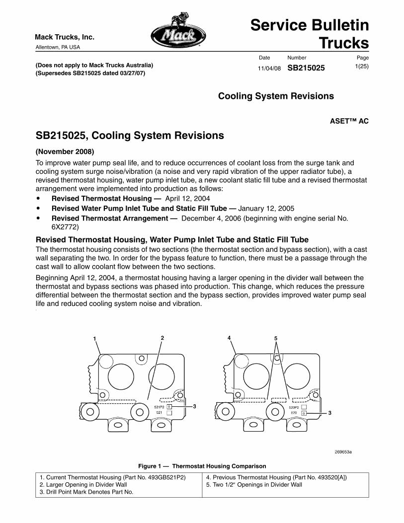
Revised Thermostat Housing, Water Pump Inlet Tube and Static Fill TubeThe thermostat housing consists of two sections (the thermostat section and bypass section), with a cast wall separating the two. In order for the bypass feature to function, there must be a passage through the cast wall to allow coolant flow between the two sections.
Beginning April 12, 2004, a thermostat housing having a larger opening in the divider wall between the thermostat and bypass sections was phased into production. This change, which reduces the pressure differential between the thermostat section and the bypass section, provides improved water pump seal life and reduced cooling system noise and vibration.1
Figure 1 — Thermostat Housing Comparison
1. Current Thermostat Housing (Part No. 493GB521P2)2. Larger Opening in Divider Wall3. Drill Point Mark Denotes Part No.
4. Previous Thermostat Housing (Part No. 493520[A])5. Two 1/2″ Openings in Divider Wall

11/04/08 SB215025Mack Trucks, Inc. Date Number Page
Service Bulletin 2(25)
Previously, the coolant return lines for the cab heater, sleeper heater and fuel heater were connected to the thermostat housing. Less pressure differential inside the thermostat housing, however, results in insufficient coolant flow through the heaters. Because of this, return lines for the cab heater, sleeper heater and fuel heater are now connected to the static fill tube.
The revised thermostat housing part No. 493GB521P2 includes the five tapped ports originally used for the coolant return lines. DO NOT use these ports for the cab and/or fuel heater coolant return lines, as adequate pressure differential does not exist and sufficient coolant flow will not be attained.
The water pump inlet tube now includes a connection for the new static fill tube. The new static fill tube arrangement includes spuds for the cab heater and fuel heater coolant return line connections.2
Figure 2 — Water Pump Inlet Tube
Should pushing coolant (coolant loss from the surge tank) or cooling system surge noise/vibration be encountered, the cooling system should be revised as outlined in the following instructions.
1. Water Pump Inlet Tube (Part No. 670GC51422. Connection for Static Fill Tube3. Static Fill Tube (Part No. 227GC516)
4. Fuel Heater Return Connection5. Cab Heater Return Connection6. Sleeper Heater Return Connection

11/04/08 SB215025Mack Trucks, Inc. Date Number Page
Service Bulletin 3(25)
Some chassis may already have been modified with some of the revisions outlined in this bulletin. For example, some chassis may be equipped with a revised thermostat housing (part No. 493GB521 or 493GB521P2), but not the static fill tube. On these chassis, the cab, sleeper and fuel heater return lines may either be connected to the lower radiator tube or to the thermostat housing. The thermostat housing will not be replaced on these chassis, but the new water pump inlet tube and static fill tube will be required. Additionally, it will be necessary to reroute the heater return lines from either the thermostat housing or the lower radiator tube to the static fill tube. This service bulletin covers all arrangements.
Thermostat Hosing and Thermostat InstallationBefore proceeding, determine if the thermostat housing must be replaced by looking at the part number located on the top of the housing (refer to Figure 1). For engines having thermostat housing part No. 493GB520(A), the existing thermostat housing must be replaced with the revised housing part No. 493GB521P2. If the engine is equipped with thermostat housing part No. 493GB521, DO NOT replace the housing, but proceed with installing the water pump inlet tube and installing the static fill tube. If equipped with 493GB521 thermostat housing, a plug (part No. 9032-7237X16) will be required to close the static fill port in the side of the housing. Parts required for replacing the thermostat housing are as follows:3
Figure 3 — Thermostat Housing Assembly
11/04/08 SB215025Mack Trucks, Inc. Date Number Page
Service Bulletin 4(25)
In addition to the parts listed above, the following parts will also be required (not shown in aboveexploded view):
Procedures for removing and reinstalling the thermostat housing are as follows:1. Disconnect the batteries by disconnecting the negative battery cable(s) first, and then the positive
battery cable(s).2. Open the hood.3. Drain the coolant into a clean container. Cover the container to prevent dirt from contaminating the
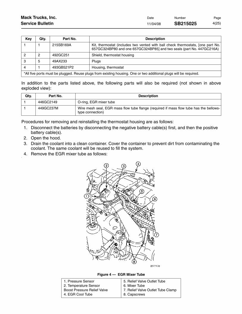
coolant. The same coolant will be reused to fill the system.4. Remove the EGR mixer tube as follows:
4
Figure 4 — EGR Mixer Tube
Key Qty. Part No. Description
1 1 215SB169A Kit, thermostat (includes two vented with ball check thermostats, [one part No.657GC324BP80 and one 657GC324BP85] and two seals (part No. 447GC216A)
2 2 492GC251 Shield, thermostat housing
3 5 49AX233 Plugs
4 1 493GB521P2 Housing, thermostat
*All five ports must be plugged. Reuse plugs from existing housing. One or two additional plugs will be required.
Qty. Part No. Description
1 446GC2149 O-ring, EGR mixer tube
1 449GC237M Wire mesh seal, EGR mass flow tube flange (required if mass flow tube has the bellows-type connection)
1. Pressure Sensor2. Temperature SensorBoost Pressure Relief Valve4. EGR Cool Tube
5. Relief Valve Outlet Tube6. Mixer Tube7. Relief Valve Outlet Tube Clamp8. Capscrews

11/04/08 SB215025Mack Trucks, Inc. Date Number Page
Service Bulletin 5(25)
a. Loosen the clamps at both coupling hoses on the inlet air duct between the charge air cooler outlet and the EGR mixer tube, and then remove the inlet air duct.
b. Disconnect the harness connectors for both the outlet pressure and temperature sensors.c. Loosen the two clamps that secure the coupling hose to the boost pressure relief valve, and
then remove the coupling hose.5
Figure 5 — Boost Pressure Relief Valve Coupling Hosed. Remove the capscrew from the support bracket at the side of the EGR mixer tube. The bracket
is attached between the mixer tube and the coolant manifold.6
Figure 6 — EGR Mixer Tube Support Bracket
1. Mixer Tube2 Mixer TUbe EGR Mass
Flow Tube Flange
3. Support Bracket4. Coolant Manifold

11/04/08 SB215025Mack Trucks, Inc. Date Number Page
Service Bulletin 6(25)
e. Loosen and remove the clamp attaching the upper EGR mass flow tube to the mixer tube. If the mass flow tube uses the bellows-type connection, remove and discard the seal in the flange.
7
Figure 7 — Upper Gas Tube-to-Mixer Connection (Bellows-Type SHown)
f. Remove the two capscrews securing the EGR mixer tube to the inlet manifold, and lift the mixer tube out of the way to gain access to the thermostat housing.
5. Disconnect the cab/sleeper heater and fuel heater (as equipped) return lines from the side of the thermostat housing.
6. Disconnect the bypass hose and the surge tank hose from the thermostat housing.
7. Remove and discard the coupling hose between the upper radiator tube and the thermostat housing.
8. Remove the thermostat housing from the water manifold.
9. Remove the 3/8Ð pipe plugs from the ports in the original thermostat housing and install them into the new housing (part No. 493GB521P2). Use thread sealant (either Teflon® tape or pipe thread sealant) and tighten the plugs to 18 lb-ft (24 N•m).
10. Place the new thermostat housing top side down (with the thermostat openings facing up) on a workbench, and then install a new shield (part No. 492GC251) with the flat side facing up (toward the installer), into each thermostat bore. An installation tool is not required. It is only necessary to use finger pressure to push the shields to their fully seated position on the bottom of the thermostat housing.
1. EGR Mixer Tube 2. EGR Mass Flow Tube

11/04/08 SB215025Mack Trucks, Inc. Date Number Page
Service Bulletin 7(25)
11. Install a new seal (part No. 447GC216A) into each of the thermostat bores. Install the seal with the metal portion facing up (toward the installer), and use seal installation tool No. J 26637-A to install the seals. The installation tool ensures that the seals are installed to the proper depth.
The two seals (part No. 447GC216A) and thermostats (part No. 657GC324BP80 [180°] and 657GC324BP85 [185°]) are included in the thermostat kit (part No. 215SB169A).
8
Figure 8 — Installing Thermostat Housing Shields and Seals
1. Thermostat Housing (Part No. 493GB521P2)
2. Shields (Part No. 492GC251), Flat Side Faces Up, Toward the Opening in the Housing.
3. Seal (Part No. 447GC216A), Metal Side Faces Up, Toward the Opening in the Housing
11/04/08 SB215025Mack Trucks, Inc. Date Number Page
Service Bulletin 8(25)
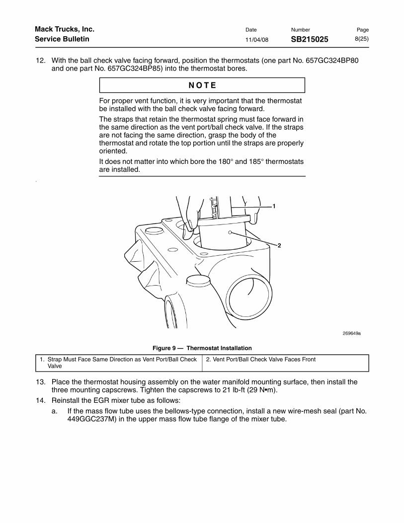
12. With the ball check valve facing forward, position the thermostats (one part No. 657GC324BP80 and one part No. 657GC324BP85) into the thermostat bores.
For proper vent function, it is very important that the thermostat be installed with the ball check valve facing forward.
The straps that retain the thermostat spring must face forward in the same direction as the vent port/ball check valve. If the straps are not facing the same direction, grasp the body of the thermostat and rotate the top portion until the straps are properly oriented.
It does not matter into which bore the 180° and 185° thermostats are installed.
9
Figure 9 — Thermostat Installation
13. Place the thermostat housing assembly on the water manifold mounting surface, then install the three mounting capscrews. Tighten the capscrews to 21 lb-ft (29 N•m).
14. Reinstall the EGR mixer tube as follows:
a. If the mass flow tube uses the bellows-type connection, install a new wire-mesh seal (part No. 449GGC237M) in the upper mass flow tube flange of the mixer tube.
1. Strap Must Face Same Direction as Vent Port/Ball Check Valve
2. Vent Port/Ball Check Valve Faces Front

11/04/08 SB215025Mack Trucks, Inc. Date Number Page
Service Bulletin 9(25)
b. Install a new O-ring (part No. 446GC2149) to the EGR mixer tube mounting collar on the inlet manifold.
10
Figure 10 — EGR Mixer Tube O-Ring Installation
c. Position the mixer tube on the inlet manifold and install the two capscrews. Tighten the capscrews to 40 lb-ft (55 N•m).
d. Install the capscrew that attaches the support bracket to the side of the mixer tube and tighten to 40 lb-ft (55 N•m).
e. With the new seal in place, position the upper EGR cool tube on the mixer tube. Install the clamp and tighten the T-bolt to 110 lb-in (12 N•m).
f. Reconnect the boost pressure relief valve by reinstalling the coupling hose and tightening the hose clamps to 28 lb-in (3.1 N•m).
g. Reconnect the outlet pressure and temperature sensor harness connectors.
1. O-Ring (Part No. 446GC2149)
2. Inlet Manifold
11/04/08 SB215025Mack Trucks, Inc. Date Number Page
Service Bulletin 10(25)
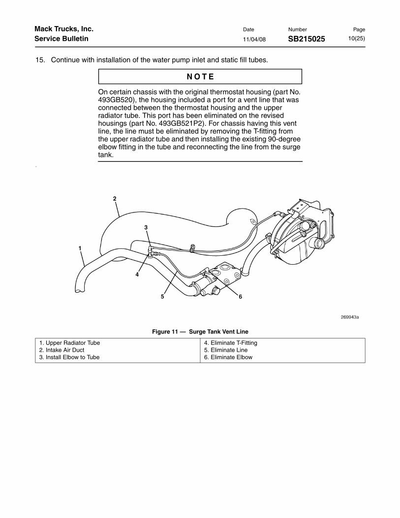
15. Continue with installation of the water pump inlet and static fill tubes.
On certain chassis with the original thermostat housing (part No. 493GB520), the housing included a port for a vent line that was connected between the thermostat housing and the upper radiator tube. This port has been eliminated on the revised housings (part No. 493GB521P2). For chassis having this vent line, the line must be eliminated by removing the T-fitting from the upper radiator tube and then installing the existing 90-degree elbow fitting in the tube and reconnecting the line from the surge tank.
11
Figure 11 — Surge Tank Vent Line
1. Upper Radiator Tube2. Intake Air Duct3. Install Elbow to Tube
4. Eliminate T-Fitting5. Eliminate Line6. Eliminate Elbow

11/04/08 SB215025Mack Trucks, Inc. Date Number Page
Service Bulletin 11(25)
On chassis manufactured between January 2002 and July 2003, the oil cooler vent line may have been connected to a T-fitting in the surge tank vent line, between the thermostat housing and upper radiator tube as shown in the illustration below. When installing the revised thermostat housing (part No. 493GB521P2) on one of these chassis, the oil cooler vent line must be rerouted and connected to any available 1/8" port on the water manifold. If a 1/8" port is not available, an available 3/8" port may be used. The water manifold used on early ASET™ AC engines only had three available ports. If this is the case and there are no available 1/8" or 3/8" ports, the oil cooler vent line can be connected to one of the available 3/8" ports on the thermostat housing. When connecting to a 3/8" port, a reducer fitting (part No. 63AX1026 will be required. For optimum routing, elbow fittings (45-degree elbow fitting part No. 63AX3909 and 90-degree elbow fitting part No. 63AX3900) may be used.
12
Figure 12 — Oil Cooler Vent Line (Chassis Manufactured Between January 2002 and July 2003)
1. To Upper Radiator Tube 2. Oil Cooler Vent Line

11/04/08 SB215025Mack Trucks, Inc. Date Number Page
Service Bulletin 12(25)
Water Pump Inlet Tube/Static Fill Tube InstallationParts required for installation of the water pump inlet and static fill tubes are as follows:13
Figure 13 — Water Pump Inlet Tube and Static FIll Tube
In addition to the parts listed above, the following parts may also be required:
Key Qty. Part No. Description
1 1 446GC2145 O-ring
2 1 670GC5142 Water pump inlet tube
3 2 83AX1026 Hose clamps
4* — 160AX543P36 Hose, 5/8" heater, 3" (7.62 mm) length
5 1 227GC516 Static fill tube
6 3** 63AX3488 Fittings, 90-degree elbow
7 1 66AM3 Bolt, M6 x 1.0 x 16 mm long with patch lock
8 1 160AX521P4 Hose, upper radiator tube-to-thermostat housing, silicone hose
1 11MF3682M10 Hose, upper radiator tube-to-thermostat housing, Gates Blue-Stripe®
9 2 83AX979 Hose clamp, for silicone hose
2 560AM3 Hose clamp, for Gates Blue-Stripe® hose
*An additional 3 feet (0.91 M) length of 5/8" heater hose will be required to replace the cab heater return line.
**Quantity dependent upon chassis equipment.
Qty. Part No. Description
2 56AX393 O-rings, coolant conditioner mounting adapter (if equipped with coolant conditioner)
1 83AX827 Cushioned P-clamp, single hose
1 83AX722 Cushioned P-clamp, double hose

11/04/08 SB215025Mack Trucks, Inc. Date Number Page
Service Bulletin 13(25)
Installation procedures for the water pump inlet tube and the static fill tube are as follows:
If not done previously, disconnect the batteries by disconnecting the negative battery cable(s) first, then the positive cable(s) and drain the coolant into a clean container.
1. Remove the Centri-Max® oil filter cover and rotor. Cover the Centri-Max® mounting adapter to prevent dirt entry.
2. If equipped with a coolant conditioner, remove the coolant conditioner canister and mounting adapter as an assembly.
14
Figure 14 — Remove Coolant Conditioner Canister and Mounting Adapter3. Remove the bolt securing the EECU harness clamp to the stand-off bracket below the EECU.
15
Figure 15 — EECU Harness Clamp

11/04/08 SB215025Mack Trucks, Inc. Date Number Page
Service Bulletin 14(25)
4. Disconnect the harness connectors from the EECU, and then position the harnesses out of the way where they will not interfere with the remaining disassembly/reassembly procedures.
5. If there are coolant lines and/or fuel lines clamped to the stand-off bracket located at the top rear of the oil cooler, remove the fastener securing the clamp(s) to the bracket.
16
Figure 16 — Remove Fuel and Coolant Line Clamps from Stand-Off Bracket
11/04/08 SB215025Mack Trucks, Inc. Date Number Page
Service Bulletin 15(25)
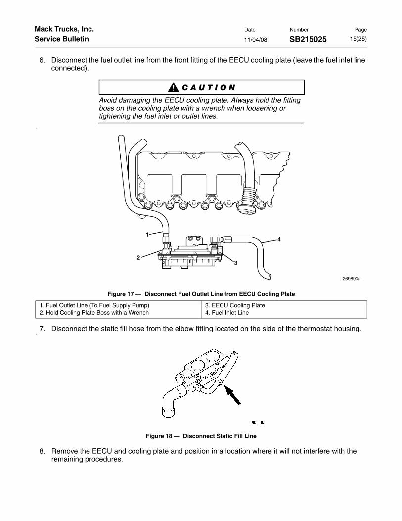
6. Disconnect the fuel outlet line from the front fitting of the EECU cooling plate (leave the fuel inlet line connected).
Avoid damaging the EECU cooling plate. Always hold the fitting boss on the cooling plate with a wrench when loosening or tightening the fuel inlet or outlet lines.
17
Figure 17 — Disconnect Fuel Outlet Line from EECU Cooling Plate
7. Disconnect the static fill hose from the elbow fitting located on the side of the thermostat housing.18
Figure 18 — Disconnect Static Fill Line
8. Remove the EECU and cooling plate and position in a location where it will not interfere with the remaining procedures.
1. Fuel Outlet Line (To Fuel Supply Pump)2. Hold Cooling Plate Boss with a Wrench
3. EECU Cooling Plate4. Fuel Inlet Line

11/04/08 SB215025Mack Trucks, Inc. Date Number Page
Service Bulletin 16(25)
9. Remove the lower radiator tube.19
Figure 19 — Remove Lower Radiator Tube
10. Remove the thermostat bypass tube and the Y-shaped hose.20
Figure 20 — Remove Thermostat Bypass Tube and Y-Shaped Hose
11. Loosen the hose clamps securing the water pump inlet tube to the coupling hose at the oil cooler coolant outlet pipe.
1. Thermostat Bypass Tube 2. Y-Shaped Hose
11/04/08 SB215025Mack Trucks, Inc. Date Number Page
Service Bulletin 17(25)
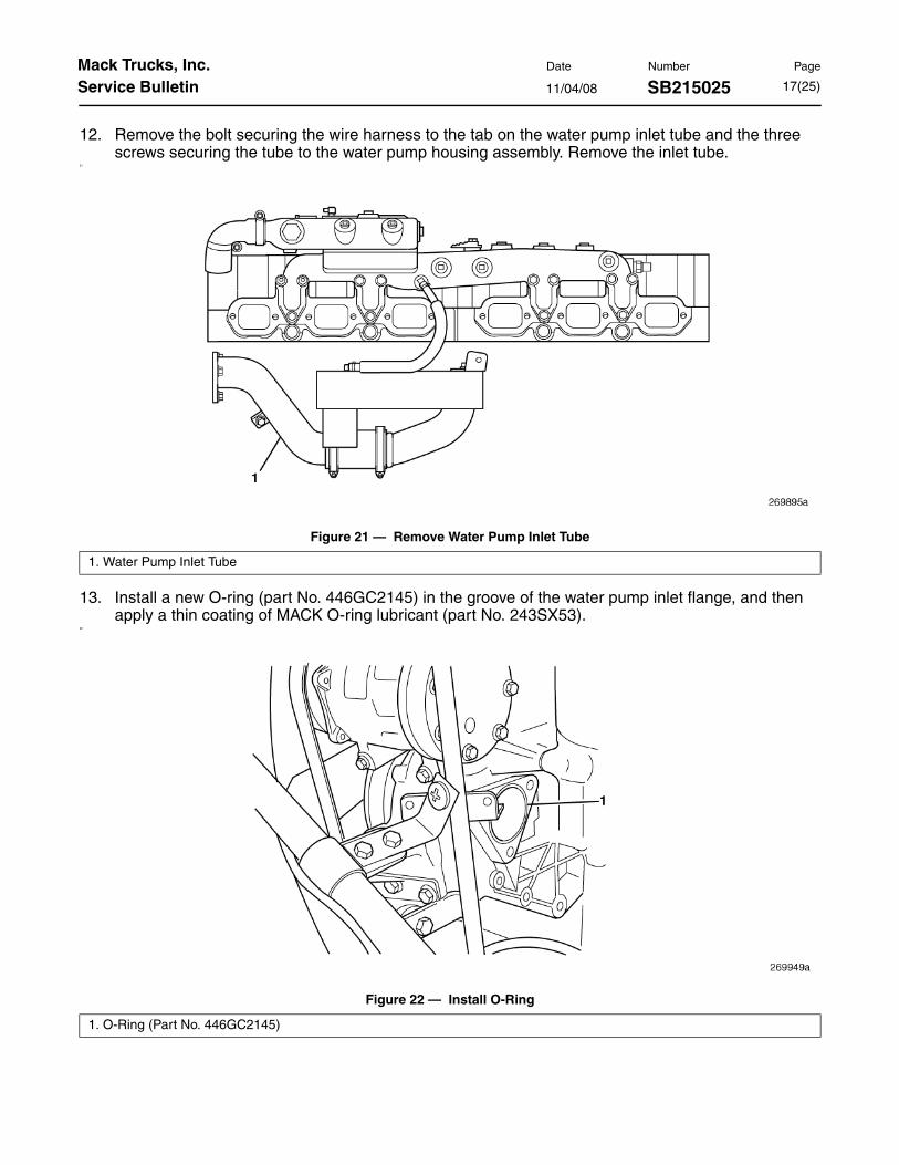
12. Remove the bolt securing the wire harness to the tab on the water pump inlet tube and the three screws securing the tube to the water pump housing assembly. Remove the inlet tube.
21
Figure 21 — Remove Water Pump Inlet Tube
13. Install a new O-ring (part No. 446GC2145) in the groove of the water pump inlet flange, and then apply a thin coating of MACK O-ring lubricant (part No. 243SX53).
22
Figure 22 — Install O-Ring
1. Water Pump Inlet Tube
1. O-Ring (Part No. 446GC2145)
11/04/08 SB215025Mack Trucks, Inc. Date Number Page
Service Bulletin 18(25)
14. Install the new water pump inlet tube (part No. 670GC5142) by sliding the tube into the coupling hose at the oil cooler and then positioning the flange against the mounting surface. Use the existing screws to secure the tube to the water pump assembly. Tighten the screws to 40 lb-ft (55 N•m). Tighten the hose clamp at the oil cooler-to-inlet tube coupling hose to 28 lb-in (3.1 N•m).
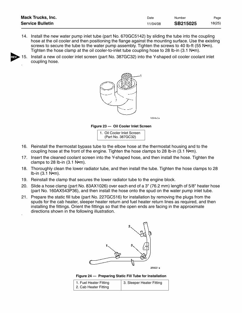
15. Install a new oil cooler inlet screen (part No. 387GC32) into the Y-shaped oil cooler coolant inlet coupling hose.
23
Figure 23 — Oil Cooler Inlet Screen
16. Reinstall the thermostat bypass tube to the elbow hose at the thermostat housing and to the coupling hose at the front of the engine. Tighten the hose clamps to 28 lb-in (3.1 N•m).
17. Insert the cleaned coolant screen into the Y-shaped hose, and then install the hose. Tighten the clamps to 28 lb-in (3.1 N•m).
18. Thoroughly clean the lower radiator tube, and then install the tube. Tighten the hose clamps to 28 lb-in (3.1 N•m).
19. Reinstall the clamp that secures the lower radiator tube to the engine block.
20. Slide a hose clamp (part No. 83AX1026) over each end of a 3" (76.2 mm) length of 5/8" heater hose (part No. 160AX543P36), and then install the hose onto the spud on the water pump inlet tube.
21. Prepare the static fill tube (part No. 227GC516) for installation by removing the plugs from the spuds for the cab heater, sleeper heater return and fuel heater return lines as required, and then installing the fittings. Orient the fittings so that the open ends are facing in the approximate directions shown in the following illustration.
24
Figure 24 — Preparing Static Fill Tube for Installation
1. Oil Cooler Inlet Screen (Part No. 387GC32)
1. Fuel Heater Fitting2. Cab Heater Fitting
3. Sleeper Heater Fitting

11/04/08 SB215025Mack Trucks, Inc. Date Number Page
Service Bulletin 19(25)
If equipped with heater shut-off valves, install the existing shut-off valves in the static fill pipe instead of the elbow fittings. For sleeper equipped chassis, an additional shut-off valve will be required, because with the original heater return line routing, the sleeper return line and the cab return line are connected together with a coupling and share the same shut-off valve.
22. Install the static fill tube to the coupling hose at the water pump inlet tube and tighten the hose clamp to 28 lb-in (3.1 N•m).
23. Reroute the static fill hose from the surge tank, and connect the hose to the static fill tube. Tighten the hose clamp to 28 lb-in (3.1 N•m). For optimum routing, it may be necessary to cut the hose to the appropriate length.
Be sure to leave enough slack in the static fill hose to allow for a full range of motion of the air suspended cab.
For engines having the 493GB521 thermostat housing, it will be necessary to remove the 90-degree elbow fitting from the static fill port on the side of the housing and install a plug and O-ring (part No. 9032-7237X16) in the port.
25
Figure 25 — Thermostat Housing Plug
The plug (part No.9032-7237X16) is only used if the engine is equipped with the 493GB521 thermostat housing.
1. Plug with O-RIng (Part No. 9032-7237X16)

11/04/08 SB215025Mack Trucks, Inc. Date Number Page
Service Bulletin 20(25)
or optimum static fill hose routing on CXN and CHN model chassis, it may be necessary to reposition the clamp that secures the air conditioner hoses to the stand-off bracket located at the top of the engine by removing the clamp, rotating it 180 degrees and reinstalling as shown in the following illustration.
26
Figure 26 — Repositioning Air Conditioner Hose Clamp

11/04/08 SB215025Mack Trucks, Inc. Date Number Page
Service Bulletin 21(25)
24. Reroute and connect the cab heater return, sleeper heater return (if equipped) and fuel heater return (if equipped) hoses to the appropriate connections on the static fuel tube as shown in the following illustration. For optimum routing, it may be necessary to cut the return hoses to proper length.
On chassis equipped with a sleeper, the return lines for both the cab and sleeper heaters are connected together by a Y-coupling located near the thermostat housing. Disconnect the sleeper heater return line from the Y-coupling and disconnect the cab heater return line from the heater core. The cab heater return line must be replaced with a single length of hose. Approximately 3 feet (1 M) of hose will be required.
27
Figure 27 — Coolant Return Hose Routing
1. To Surge Tank2. Cab Heater Return
3. Sleeper Heater Return4. Fuel Heater Return
11/04/08 SB215025Mack Trucks, Inc. Date Number Page
Service Bulletin 22(25)
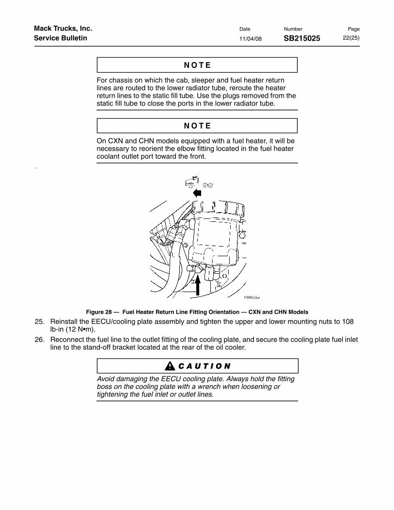
For chassis on which the cab, sleeper and fuel heater return lines are routed to the lower radiator tube, reroute the heater return lines to the static fill tube. Use the plugs removed from the static fill tube to close the ports in the lower radiator tube.
On CXN and CHN models equipped with a fuel heater, it will be necessary to reorient the elbow fitting located in the fuel heater coolant outlet port toward the front.
28
Figure 28 — Fuel Heater Return Line Fitting Orientation — CXN and CHN Models
25. Reinstall the EECU/cooling plate assembly and tighten the upper and lower mounting nuts to 108 lb-in (12 N•m).
26. Reconnect the fuel line to the outlet fitting of the cooling plate, and secure the cooling plate fuel inlet line to the stand-off bracket located at the rear of the oil cooler.
Avoid damaging the EECU cooling plate. Always hold the fitting boss on the cooling plate with a wrench when loosening or tightening the fuel inlet or outlet lines.

11/04/08 SB215025Mack Trucks, Inc. Date Number Page
Service Bulletin 23(25)
27. Route and clamp the return lines and fuel lines to provide adequate clearance and to prevent rubbing and chafing. Use a new bolt (part No. 66AM3) to secure the static fill tube and the various coolant and fuel line clamps to the stand-off bracket located at the top rear of the oil cooler.
Depending upon chassis model and equipment (sleeper, fuel heater, etc.), the coolant supply and return lines for the sleeper and fuel heater, and the fuel supply line to the EECU cooling plate were secured to the same stand-off bracket where the static fill tube is secured. With the coolant return lines rerouted to the static fill tube, only the coolant supply lines for the fuel heater and/or sleeper heater, along with the fuel supply line, will be clamped to the stand-off bracket. Use cushioned P-clamps (part No. 83AX722 for two hoses or part No. 83AX827 for a single hose) to secure the hose(s) to the stand-off bracket. Use tie wraps to secure the hoses as necessary to prevent rubbing and chafing.
29
Figure 29 — Cab Heater, Sleeper Heater and Fuel Heater Line Routing
Key Qty, Part No. Description
1 1 66AM3 Bolt, M6 x 1.0 x 16 mm long with patch lock
2 1 83AX722 P-clamp, cushioned (for two hoses)
1 83AX827 P-clamp, cushioned (for one hose)

11/04/08 SB215025Mack Trucks, Inc. Date Number Page
Service Bulletin 24(25)
28. Install a new radiator tube-to-thermostat housing coupling hose and new hose clamps. Tighten the hose clamps to 27.5 lb-in (3.1 N•m).
30
Figure 30 — Upper Radiator Tube Coupling Hose
29. Reinstall the Centri-Max® rotor and filter cover, and tighten the cover nut to 19 lb-ft (26 N•m).
30. Install O-rings (part No. 56AX393) into the two ports on the coolant conditioner mounting adapter and apply a thin coating of MACK O-ring lubricant (part No. 243SX41).
31. Reinstall the coolant conditioner mounting adapter and canister. Tighten the mounting bolts to 15 lb-ft (20 N•m).
32. Refill the cooling system with the same coolant that was originally drained.
33. Reconnect the batteries by connecting the positive battery cable(s) first, and then the negative cable(s).
34. Start the engine and check for coolant leaks.
35. Stop the engine and recheck the coolant level. Replenish with coolant as required, start the engine and recheck the coolant level as required until the cooling system has been thoroughly de-aerated.
Key Qty, Part No. Description
1 1 160AX521P4 Hose, silicone, upper radiator tube-to-thermostat housing
1 11MF3682M10 Hose, Gates Blue Stripe®, upper radiator tube-to-thermostat housing
2 2 83AX979 Clamps, for use with silicone hose
2 560AM3 Clamps, for use with Gates Blue Stripe® hose

11/04/08 SB215025Mack Trucks, Inc. Date Number Page
Service Bulletin 25(25)
ReimbursementExpenses incurred for failed components will be reimbursed through the standard warranty claim process. Pro-active upgrades are not accepted as warrantable. Labor codes and maximum labor allowances are as follows:
Mack Trucks, Inc. engages in a continuous program of testing and evaluating to provide the best possible product. Mack Trucks, Inc., however, is not committed to, or liable for updating existing chassis.
This Repair may be eligible for reimbursement if a product failure was experienced within the time and mileage limits of the applicable warranty coverage. Reimbursement is obtained via normal claim handling process.
Claim Type (used only when uploading from the Dealer Bus. Sys.) 01
Labor Code
Primary Labor Code 215 9D 23 80 — 2.0 hr., time allowed to remove andreplace existing water pump inlet tube, install newstatic fill tube, reroute and connect cab heatercoolant return line. Does not include “take-charge”time.
215 9E 23 80 — 0.2 hr., additional time to reroute and connect sleeper heater coolant return line. Does not include “take-charge” time.
215 9F 23 80 — 0.2 hr., additional time to reroute and connect fuel heater coolant return line. Does not include “take-charge” time.
215 9G 23 80 — 0.6 hr., Additional time to remove and replace thermostat housing. Does not include “take-charge” time.
Causal Part Not Applicable