asian review of mechanical engineering issn: 2231-6108 vol. 5 no. 2 ... · catia v5 is mechanical...
TRANSCRIPT
Asian Review of Mechanical Engineering ISSN: 2231-6108 Vol. 5 No. 2, 2016, pp. 18-30
© The Research Publication, www.trp.org.in
Automatic Disc Braking System Experimental Investigation
A.Karthick1 and L.Prakash2
1.Assistant Professor, 2.UG Scholar Department of Mechanical Engineering,
Adithya Institute of Technology, Coimbatore,Tamil Nadu,India Email: [email protected]
Abstract - The main objective of this project is for security system. If vehicle moves very near to the opposite vehicle then it applies brake automatically. It is used for avoiding accident over by racing in highways and parking or busy traffic areas through pneumatic braking. Pneumatic braking system works faster when compared to other devices. So we can achieve the high efficient operation by programming the microcontroller. The disc brake is a device for slowing or stopping the rotation of a wheel. Friction causes the disc and attached wheel to slow or stop. Brakes convert friction to heat, but if the brakes get too hot, they will cease to work because they cannot dissipate enough heat. This condition of failure is known as brake fade. Disc brakes are exposed to large thermal stresses during routine braking and extraordinary thermal stresses during hard braking. Keywords: Disk Braking System,Expremental Investgation.
I. INTRODUCTION
A brake is a device by means of which artificial frictional resistance is applied to moving machine member, in order to stop the motion of a machine. In the process of performing this function, the brakes absorb either kinetic energy of the moving member or the potential energy given up by objects being lowered by hoists, elevators etc. The energy absorbed by brakes is dissipated in the form of heat. Disc brake is familiar automotive application where they are used extensively for car and motorcycle wheels. This is sandwiched between two pads actuated by pistons supported in a caliper mounted on the stud shaft. When the brake lever is pressed hydraulically pressurized fluid is forced into the cylinders pushing the opposing pistons and brake pads into frictional contact with the disc Friction brakes act by generating frictional forces as two or more surfaces rub against each other. The stopping power or capacity of a friction brake depends on the area in contact and coefficient of friction of the working surfaces as well as on the actuation pressure applied. Wear occurs on the working surfaces, and the durability of a given brake (or service life between maintenance) depends on the type of friction material used for the replaceable surfaces of the brake. If drake disc are in solid body the Heat transfer rate is low. Time taken for cooling the disc is low. If brake disc are in solid body, the area of contact between Disc and Pads are more, so efficiency of brake is high. We introduced superimpose
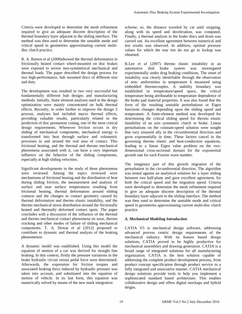
variation cut pattern on the disc in disc brake. The number of cuts Pattern introduce in disc The Heat transfer rate is increase. Time taken for cooling the disc is high. If the number of cut is increase in the disc, the area of contract between the disc and pads were reduces, so efficiency of brake is high. The number of cut was increase the strength of the disc also reduces. So it can easily break. So the number of cuts in the disc with in the limit, It can help to Heat transfer rate of the disc and the area of contact between Disc and Pads are not reduces and efficiency of brake must be same.
II. LITERATURE SURVEY
Floquet et al (2009) determined of temperature distribution and comparison of simulation results and experimental results in the disc by 2D thermal analysis using axisymmetric model. The disc brake used in the automobile is divided into two parts; a rotating ax symmetrical disc, and the stationary pads. The friction heat, which is generated on the interface of the disc and pads, can cause high temperature during the braking process. The influence of initial velocity and deceleration on cooling of the brake disc was also investigated. The thermal simulation is used to characterize the temperature field of the disc with appropriate boundary conditions. A Finite-element method was developed for determining the critical sliding speed for thermo elastic instability of an axisymmetric clutch or brake. Linear perturbations on the constant-speed solution were sought that vary sinusoid ally in the circumferential direction and grow exponentially in time. These factors cancel in the governing thermo elastic and heat-conduction equations, leading to a linear eigenvalue problem on the two dimensional cross-sectional domain for the exponential growth rate for each Fourier wave number. The imaginary part of this growth rate corresponds to a migration of the perturbation in the circumferential direction. The algorithm was tested against an analytical solution for a layer sliding between two half-planes and provided excellent agreement, for both the critical speed and the ,migration speed.
18ARME Vol.5 No.2 July-December 2016
Criteria were developed to determine the mesh refinement required to give an adequate discrete description of the thermal boundary layer adjacent to the sliding interface. The method was then used to determine the unstable mode and critical speed in geometries approximating current multi-disc clutch practice. R. A. Burton et al (2008)showed the thermal deformation in frictionally heated contact wheel-mounted on disc brakes were exposed to severe non-symmetrical mechanical and thermal loads. The paper described the design process for two high-performance, hub mounted discs of different size and duty. The development was resulted in two very successful but fundamentally different hub designs and manufacturing methods. Initially, finite element analyses used in the design optimization were mainly concentrated on bulk thermal effects. Recently, in order further to improve the design 5 process, analyses had included macro thermal effects, providing valuable results, particularly related to the prediction of disc permanent coning, one of the most critical design requirements. Whenever friction occurs in dry sliding of mechanical components, mechanical energy is transformed into heat through surface and volumetric processes in and around the real area of contact. This frictional heating, and the thermal and thermo mechanical phenomena associated with it, can have a very important influence on the behavior of the sliding components, especially at high sliding velocities. Significant developments in the study of these phenomena were reviewed. Among the topics reviewed were mechanisms of frictional heating and the distribution of heat during sliding friction, the measurement and analysis of surface and near surface temperatures resulting from frictional heating, thermal deformation around sliding contacts and the changes in contact geometry caused by thermal deformation and thermo elastic instability, and the thermo mechanical stress distribution around the frictionally heated and thermally deformed contact spots. The paper concludes with a discussion of the influence of the thermal and thermo mechanical contact phenomena on wear, thermo cracking and other modes of failure of sliding mechanical components. T. A. Dowat et al (2012) proposed to contribute to dynamic and thermal analysis of the braking phenomenon. A dynamic model was established. Using this model the equation of motion of a car was derived for straight line braking. In this context, firstly the pressure variations in the brake hydraulic circuit versus pedal force were determined. Afterwards, the expression for friction torques and associated braking force induced by hydraulic pressure was taken into account, and substituted into the equation of motion of vehicle. In its last form, this equation was numerically solved by means of the new mark integration
scheme; so, the distance traveled by car until stopping, along with its speed and deceleration, was computed. Finally, a thermal analysis in the brake discs and drum was carried out. An excellent agreement between numerical and test results was observed. In addition, optimal pressure values for which the rear tire do not go to lockup was obtained. K.Lee et al (2007) thermo elastic instability in an automotive disk brake system was investigated experimentally under drag braking conditions. The onset of instability was clearly identifiable through the observation of non- uniformities in temperature 6 measured using embedded thermocouples. A stability boundary was established in temperature/speed space, the critical temperature being attributable to temperature dependence of the brake pad material properties. It was also found that the form of the resulting unstable perturbations or Eigen functions changes depending upon the sliding speed and temperature. A finite-element method was developed for determining the critical sliding speed for thermo elastic instability of an axis symmetric clutch or brake. Linear perturbations on the constant-speed solution were sought that vary sinusoid ally in the circumferential direction and grow exponentially in time. These factors cancel in the governing thermo elastic and heat-conduction equations, leading to a linear Eigen value problem on the two-dimensional cross-sectional domain for the exponential growth rate for each Fourier wave number. The imaginary part of this growth migration of the perturbation in the circumferential direction. The algorithm was tested against an analytical solution for a layer sliding between two half-plane and gave excellent agreement, for both the critical speed and the migration speed. Criteria were developed to determine the mesh refinement required to give an adequate discrete description of the thermal boundary layer adjacent to the sliding interface. The method was then used to determine the unstable mode and critical speed in geometries approximating current multi-disc clutch practice. A. Mechanical Modeling Introduction CATIA V5 is mechanical design software, addressing advanced process centric design requirements of the mechanical industry. With its feature based design solutions, CATIA proved to be highly productive for mechanical assemblies and drawing generation. CATIA is a broad range of integrated solutions for all manufacturing organization. CATIA is the best solution capable of addressing the complete product development process, from product concept specification through product service in a fully integrated and associative manner. CATIA mechanical design solutions provide tools to help you implement a sophisticated standard based architecture. This enables collaborative design and offers digital mockups and hybrid deigns.
19 ARME Vol.5 No.2 July-December 2016
Automatic Disc Braking System Experimental Investigation
The domain includes:
1. Product design & manufacturing.2. Drawing enterprise competitiveness3. Task presentation
CATIA V5 is totally compliant with windows presentation standards. CATIA V5 provides a unique two way interoperability with CATIA version4 data. As an open solution, CATIA includes with the most commonly used data exchange industry standards. CATIA V5 R17 extends the power of leading edge engineering practices to include relation design, which results in,
1. Higher Quality design2. More opportunities for innovation3. Fewer engineering changes
B.Sketcher
CATIA sketcher tools initially drafts a rough sketch following the shape of the profile. The objects created are converted into a proper sketch by applying geometric constraints and dimensional constraints. These constraints refine the sketch according to a rule. Adding parametric dimensions further control the shape and size of the feature. Pad, groove, slot etc., are used as one of the feature creation tools to convert the sketcher entity into a part feature.
PART DESIGN The CATIA V5 is a 3D parametric solid modeler with both part and assembly modeling abilities. You can use CATIA to model simple parts and then combine them into more complex assemblies. With CATIA, you design a part by sketching its component shapes and defining their size, shape, and inter relationships. By successively creating these shapes, called features, you can construct the part. The general modeling process:
1. Planning concept of designing2. Creation of base feature3. Completion of other features4. Analyzing the part design5. Modifying the design as necessary
[1] Assembly Design Catia Assembly design gives the user the ability to design with user controlled associability. CATIA builds individual parts and subassemblies into an assembly in a hierarchical manner according to the relationships defined by constraints. As in part modeling, the parametric relationships allow you to quickly update an entire assembly based on a change in one of its parts.
The general assembly process- 1. Layout the assembly2. Based on design follow either top down or bottom up3. Analyze the assembly4. Modifying the assembly
C. Drafting Drawings and documentation are the true products of design because they guide the manufacture of a mechanical device. CATIA automatically generate associative drafting from 3D mechanical designers and assemblies..CATIA enriches Generative Drafting with both integrated 2D interactive functionality and a productive environment for drawings dress-up and annotation.
III. DESCRIPTION OF EQUIPMENTS
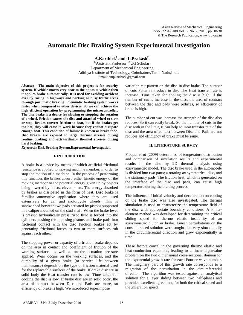
A. Disc brake A disc brake consists of a cast iron disc bolted to the wheel hub and a stationary housing called caliper. The caliper is connected to some stationary part of the vehicle like the axle casing or the stub axle as is cast in two parts each part containing a piston. In between each piston and the disc there is a friction pad held in position by retaining pins, spring plates etc. passages are drilled in the caliper for the fluid to enter or leave each housing. The passages are also connected to another one for bleeding. Each cylinder contains rubber-sealing ring between the cylinder and piston. A schematic diagram is shown in the figure 3.1.
The main components of the disc brake are:
a. The Brake Padsb. The Caliper which contains the pistonc. The Rotor, which is mounted to the hub
Fig.3.1 Disc Brake
20ARME Vol.5 No.2 July-December 2016
A.Karthick and L.Prakash
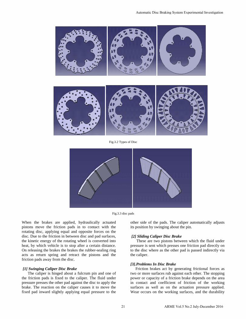
Fig.3.2 Types of Disc
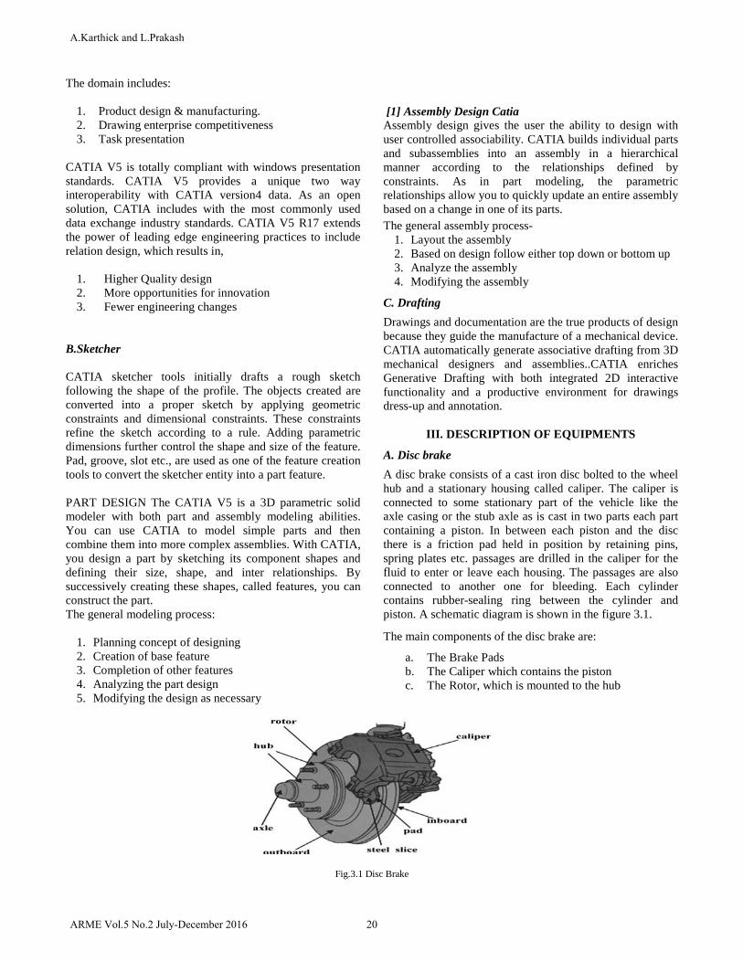
Fig.3.3 disc pads
When the brakes are applied, hydraulically actuated pistons move the friction pads in to contact with the rotating disc, applying equal and opposite forces on the disc. Due to the friction in between disc and pad surfaces, the kinetic energy of the rotating wheel is converted into heat, by which vehicle is to stop after a certain distance. On releasing the brakes the brakes the rubber-sealing ring acts as return spring and retract the pistons and the friction pads away from the disc.
[1] Swinging Caliper Disc Brake The caliper is hinged about a fulcrum pin and one of the friction pads is fixed to the caliper. The fluid under pressure presses the other pad against the disc to apply the brake. The reaction on the caliper causes it to move the fixed pad inward slightly applying equal pressure to the
other side of the pads. The caliper automatically adjusts its position by swinging about the pin.
[2] Sliding Caliper Disc Brake These are two pistons between which the fluid under pressure is sent which presses one friction pad directly on to the disc where as the other pad is passed indirectly via the caliper.
[3].Problems In Disc Brake Friction brakes act by generating frictional forces as two or more surfaces rub against each other. The stopping power or capacity of a friction brake depends on the area in contact and coefficient of friction of the working surfaces as well as on the actuation pressure applied. Wear occurs on the working surfaces, and the durability
21 ARME Vol.5 No.2 July-December 2016
Automatic Disc Braking System Experimental Investigation
of a given brake (or service life between maintenance) depends on the type of friction material used for the replaceable surfaces of the brake.
If drake disc are in solid body the Heat transfer rate is low. Time taken for cooling the disc is low. If brake disc are in solid body, the area of contact between Disc and Pads are more, so efficiency of brake is high.
We introduced superimpose variation cut pattern on the disc in disc brake. The number of cuts Pattern introduce in disc The Heat transfer rate is increase. Time taken for cooling the disc is high. If the number of cut is increase in the disc, the area of contract between the disc and pads were reduces, so efficiency of brake is high. The number of cut was increase the strength of the disc also reduces. So it can easily break. So the number of cuts in the disc with in the limit, It can help to Heat transfer rate of the disc and the area of contact between Disc and Pads are not reduces and efficiency of brake must be same.
[4]. Objective Of The Present Study The present investigation is aimed to study: a. The given disc brake of its stability and rigidity (for
this Thermal
b. Analysis and structural analysis is carried out on agiven disc brake.
c. Best combination of parameters of disc brake likeCutting pattern in disc and material there by a bestcombination is suggested.
d. And the best combination of parameters of disc brakeis optimistic by a best is suggested.
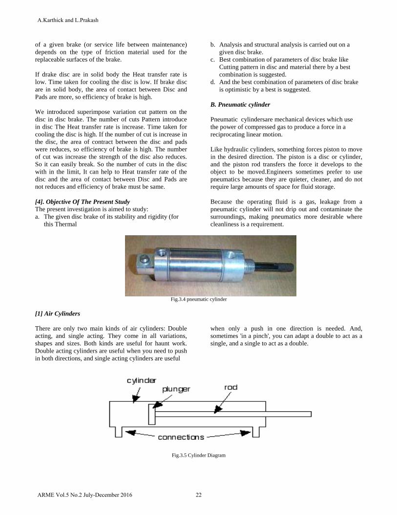
B. Pneumatic cylinder
Pneumatic cylindersare mechanical devices which use the power of compressed gas to produce a force in a reciprocating linear motion.
Like hydraulic cylinders, something forces piston to move in the desired direction. The piston is a disc or cylinder, and the piston rod transfers the force it develops to the object to be moved.Engineers sometimes prefer to use pneumatics because they are quieter, cleaner, and do not require large amounts of space for fluid storage.
Because the operating fluid is a gas, leakage from a pneumatic cylinder will not drip out and contaminate the surroundings, making pneumatics more desirable where cleanliness is a requirement.
Fig.3.4 pneumatic cylinder
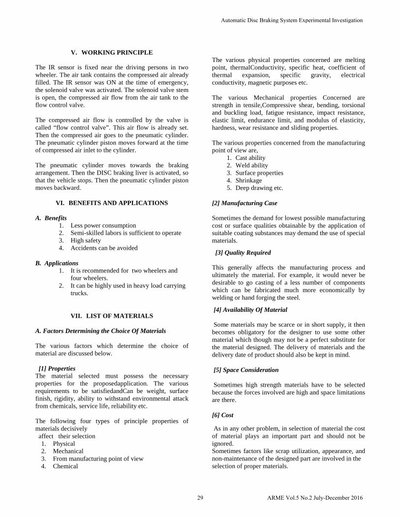
[1] Air Cylinders
There are only two main kinds of air cylinders: Double acting, and single acting. They come in all variations, shapes and sizes. Both kinds are useful for haunt work. Double acting cylinders are useful when you need to push in both directions, and single acting cylinders are useful
when only a push in one direction is needed. And, sometimes 'in a pinch', you can adapt a double to act as a single, and a single to act as a double.
Fig.3.5 Cylinder Diagram
22ARME Vol.5 No.2 July-December 2016
A.Karthick and L.Prakash

[2] Single Acting Cylinder
Single Acting means the air cylinder rod is only pushed in a single direction, either out or in. There is only one connection for air, and a little hole in the other end to let air in and out. A spring is used to push the rod in the opposite direction after air pressure is removed.Single Acting Air Cylinder, with the rod normally out without pressure.
As air is pushed into the connection, the plunger begins to move and compress the spring. Exhaust air exits out the exhaust hole on the other end. When air is released, it exits out the connection, and air is sucked into the exhaust hole as the spring pushes the plunger back to its resting
position. Basically, the spring is ‘push’ needed to return the plunger and rod back to their starting position.
When selecting a cylinder for an application, remember that a double acting cylinder pushes in both directions, while a single acting cylinder only pushes in one direction.
Fig.3.6 cylinderwithout Pressure
Fig.3.7 CylinderWith Pressure
[3]Mounting
There are about as many ways to mount an air cylinder as there are different types of air cylinders. Again, this is because of all the uses. Clevis mounts give the greatest amount of movement, flexibility, and ease of mounting over other mounts.
C. Solenoid valves
Here’s the most confusing part of dealing with pneumatics – solenoids. Just like air cylinders, they come in all sizes, styles, shapes, sizes, and combinations. There’s literally something for everyone when it comes to solenoids.
The whole ‘four port ’,‘ five ports, ‘two way’, ‘three way’, naming came from the action of the air as it moves through the solenoid. Again, the names aren’t as important as what it does. The best combination of flexibility and use for double acting cylinders is what’s called a “five port, four way” solenoid (they’re also called ‘valves’).
[1] Five Port, Four Way Solenoid
Fig.3.8 Solenoid valve
A five port solenoid has just that - five connections called ports. Usually, they are labeled A, B, E1, E2, and In. There are variations of this too. In most cases, any pair of ports that have a label that has an 'A & B', '1 & 2', 'A1 & A2' - that's the ports that connect to the air cylinder. Exhaust ports almost always have an 'E' in the name. There is almost always a single 'In'. Notice the phrase 'almost always' - that's because there are cases where solenoids have several sets of in's and out's to fill a particular application. Thus is the 'five port' part.
23 ARME Vol.5 No.2 July-December 2016
Automatic Disc Braking System Experimental Investigation

Fig. 3.9 Solenoid off
The 'four way' term describes the paths that air can take when the solenoid is in operation. Use the drawing to follow this description. When a four way solenoid is 'off' or 'de-energized', air will flow through from the In to the A port (that's one way), and also let out of port B through port E1 (two ways). So air goes in through the In port, and out the A port to push the cylinder, and it lets air out of port B (through E1).
Fig. 3.10 Solenoid on
And when the solenoid is 'on', (energized), air pressure from the In port flows to the B port (the third way), and exhaust air is let out of port A through port E2 (the fourth way).
An important characteristic of the 5 port, 4way solenoid is called "orifice" size. This is the size of the internal air paths through the solenoid. Its usually quoted is diameter. An orifice of at least 1/8" is recommended, with a size of 1/4" preferred. The orifice size directly affects the solenoids air flow. The more air it can move, the faster an air cylinder can move. Four port, Four way variation of the five port, four way combines the two exhaust ports into one single exhaust. So it is called a four port.
Fig.3.11 Double acting air cylinder connected to 5 Port, 4 Way solenoid
[2 ] Fittings
There are two very useful fittings: Push-in (or Push-on), and quick-connect. The quick-connect are the standard fittings seen mostly at a gas station. They are extremely useful to 'quickly' connect and disconnect air to props. The Push-in connectors are very useful to connect solenoids to air cylinders. Both of these connector types are highly recommended.
[3] Regulators And Filters
Most air systems include air regulators, particle filters, water filters, and manual valves to deliver good air to the solenoids and air cylinders.
The most important of these is the air regulator. This unit sets the overall pressure for your air system. A good starting pressure to run a few popups is 60 psi or less. If you're supporting a large air system with lots of popups and long airlines, 70-80 psi is not excessive. However, pressures beyond 80 psi will begin to 'stress' the entire system, and show itself in small leaks around fittings, wear and tear of popup mechanisms, and long running times for the compressor.
You may also consider having several regulators in your air system. This gives you the option of optimizing just the right amount of air to each place. For example, a jumper popup may only need 30psi to work. Running it on your 60 psi system will eventually wear it out. Placing a regulator just before the jumper's solenoid lets you reduce air pressure and just give the jumper what it needs to run.
Particle and water filters are useful items to use to keep your air lines free from debris and moisture. Debris will clog air lines, solenoids and cause erratic or intermittent operation. Moisture in the air will cause rust to form.There are also lubricators that add a small amount of oil to the air to keep the mechanics working smoothly.
D. Air compressor
Compressor is the air producing machine. They collect the airs from the atmosphere are in the running of machine are engine. Air compressors are utilized to raise the pressure of a volume of air. Air compressors are available in many configurations and will operate over a very wide range of flow rates and pressures. Compressed air was expelled by primitive man to give glowing embers sufficient oxygen to allow them to flare up into a fire. During the compression process, the temperature increases as the pressure increases. This is known as polytypic compression. The amount of compression power also increases as the temperature increases. Compressors are staged thereby reducing the temperature rise and improving the compression efficiency. The
24ARME Vol.5 No.2 July-December 2016
A.Karthick and L.Prakash

temperature of the air leaving each stage is cooled prior to entering the next stage. This cooling process is called intercooling. Volumetric efficiency also increases with multi-stage compression since the pressure ratio over the first stage will be decreased.
Selection of the air compressor is only the first step in designing an efficient and reliable compressed air system. The air exiting the compressor is saturated with moisture and will have compressor lubricants (lubricated compressors only). Other chemicals that may have been drawn into the compressor intake may also be present. This contamination is harmful to many processes, pneumatic tools, instruments and equipment. Air purification equipment, filters, air dryers, breathing air purifiers, monitoring equipment, used alone or in combination will remove these contaminants. Selection and purchase of the compressor and necessary purification equipment can be easily done on the Compressed air site. Our application engineers are ready to answer all of your questions and to assist you in placing your order. And it work in the process of rotating the fan and the piston movement with the help of current supply.
E. Control unit
In our project the main device is a micro controller. It is used to control the whole unit of this project. The micro controller is connected to the control unit. The control unit is connected with the battery to get the power supply.
Microcontrollers are destined to play an increasingly important role in revolutionizing various industries and influencing our day to day life more strongly than one can imagine. Since its emergence in the early 1980's the microcontroller has been recognized as a general purpose building block for intelligent digital systems. It is finding using diverse area, starting from simple children's toys to highly complex spacecraft. Because of its versatility and many advantages, the application domain has spread in all conceivable directions, making it ubiquitous. As a consequence, it has generate a great deal of interest and enthusiasm among students, teachers and practicing engineers, creating an acute education need for imparting the knowledge of microcontroller based system design and development. It identifies the vital features responsible for their tremendous impact; the acute educational need created by them and provides a glimpse of the major application area.
Fig. 3.12 Air Compressor
[1] Advantages Of Microcontrollers
If a system is developed with a microprocessor, the designer has to go for external memory such as RAM, ROM or EPROM and peripherals and hence the size of the PCB will be large enough to hold all the required peripherals. But, the micro controller has got all these peripheral facilities on a single chip so development of a similar system with a micro controller reduces PCB size and cost of the design.
One of the major differences between a micro controller and a microprocessor is that a controller often deals with bits , not bytes as in the real world application, for example switch contacts can only be open or close, indicators should be lit or dark and motors can be either turned on or off and so forth.
F. IR Sensor
[1] Schematic Explanation
This circuit is designed to control the load. The load may be motor or any other load. The load is turned ON and OFF through relay. The relay ON and OFF is controlled by the pair of switching transistors (BC 547). The relay is connected in the Q2 transistor collector terminal. A Relay is nothing but electromagnetic switching device which consists of three pins. They are Common(3rd pin), Normally close (5th pin) and Normally open (4th pin).
The relay common pin is connected to supply voltage. The normally open (NO) pin connected to load. When high(5 volt) pulse signal is given to base of the Q1 transistors, the transistor is conducting and shorts the collector and emitter terminal and zero(0 Volt) signals is given to base of the Q2 transistor. So the relay is turned OFF state.
When low pulse is given to base of transistor Q1 transistor, the transistor is turned OFF. Now 12v is given to base of Q2 transistor so the transistor is conducting and relay is turned ON. Hence the common terminal and NO terminal of relay are shorted. Now load gets the supply voltage through relay.
25 ARME Vol.5 No.2 July-December 2016
Automatic Disc Braking System Experimental Investigation
[2 ] PCB Layout
Fig. 3.13 PCB Layout
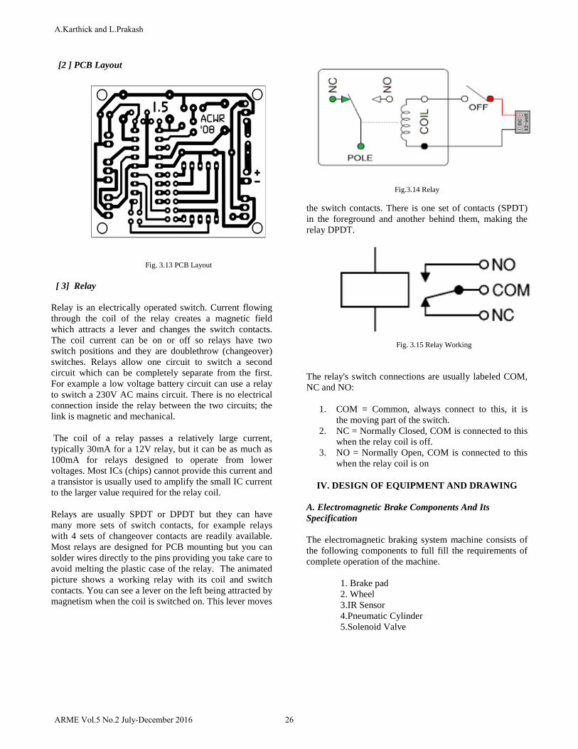
[ 3] Relay
Relay is an electrically operated switch. Current flowing through the coil of the relay creates a magnetic field which attracts a lever and changes the switch contacts. The coil current can be on or off so relays have two switch positions and they are doublethrow (changeover) switches. Relays allow one circuit to switch a second circuit which can be completely separate from the first. For example a low voltage battery circuit can use a relay to switch a 230V AC mains circuit. There is no electrical connection inside the relay between the two circuits; the link is magnetic and mechanical.
The coil of a relay passes a relatively large current, typically 30mA for a 12V relay, but it can be as much as 100mA for relays designed to operate from lower voltages. Most ICs (chips) cannot provide this current and a transistor is usually used to amplify the small IC current to the larger value required for the relay coil.
Relays are usually SPDT or DPDT but they can have many more sets of switch contacts, for example relays with 4 sets of changeover contacts are readily available. Most relays are designed for PCB mounting but you can solder wires directly to the pins providing you take care to avoid melting the plastic case of the relay. The animated picture shows a working relay with its coil and switch contacts. You can see a lever on the left being attracted by magnetism when the coil is switched on. This lever moves
Fig.3.14 Relay
the switch contacts. There is one set of contacts (SPDT) in the foreground and another behind them, making the relay DPDT.
Fig. 3.15 Relay Working
The relay's switch connections are usually labeled COM, NC and NO:
1. COM = Common, always connect to this, it isthe moving part of the switch.
2. NC = Normally Closed, COM is connected to thiswhen the relay coil is off.
3. NO = Normally Open, COM is connected to thiswhen the relay coil is on
IV. DESIGN OF EQUIPMENT AND DRAWING
A. Electromagnetic Brake Components And Its Specification
The electromagnetic braking system machine consists of the following components to full fill the requirements of complete operation of the machine.
1. Brake pad2. Wheel3.IR Sensor4.Pneumatic Cylinder5.Solenoid Valve
26ARME Vol.5 No.2 July-December 2016
A.Karthick and L.Prakash

Relay Data Sheet
TABLE 3.1 RELAY DATA SHEET
CLASSIFICATION PCB RELAY Product Model JQC-3F(T73)
Outline Dimension(L×W×H) (mm) 19×15.5×15.5(mm)
Contact Form 1Z,1H,1D
Contact Resistance 100mΩ (1A 6VDC)
Coil Voltage 3VDC~48VDC
Operate Time (at nomi. Volt) 15ms
Release Time (at nomi. Volt) 10ms
Coil Power(W) 0.36
Contact Rating 7A/10A 250VAC 10A/15A 28VDC 10A/15A 120VAC
Insulation Resistance 1000MΩ,500VDC
Dielectric Strength
Between Open Contact 500VAC Between Coil and Contact 750VAC
Electrical Life 1×10⁵
Mechanical Life 1×10⁷
Max. Switching Voltage 250VAC/30VDC
Max. Switching Current 15A
Max. Switching Power 300W/2500VA
Impact Resistance Stability 100m/s2 Intensity 1000m/s2
Humidity 35%~95% R.H.
Temperature Range -40~+80°C
Vibration Resistance 1mm 10~55Hz
Mounting Form PCB Terminal
Weight 9g
Construction Sealed IP67
B. Block Diagram Of Braking System
Fig. 4.1Block diagram of braking system
IR SENSOR
MICROCONTROLLER
RELAY
SOLENOID VALVE
PNEUMATIC CYLINDER
27 ARME Vol.5 No.2 July-December 2016
Automatic Disc Braking System Experimental Investigation

C. Automatic Disc Braking System
Fig. 4.2Automatic disc braking system
Fig. 4.3 Circuit of IR Sensor D. IR Detection
This circuit is designed to control the load. The load may be motor or any other load. The load is turned ON and OFF through relay. The relay ON and OFF is controlled by the pair of switching transistors (BC 547).
The relay is connected in the Q2 transistor collector terminal. A Relay is nothing but electromagnetic switching device which consists of three pins. They are Common(3rd pin), Normally close (5th pin) and Normally open (4th pin)
E. Sensor Circuit
Fig.4.4 Sensor kit
28ARME Vol.5 No.2 July-December 2016
A.Karthick and L.Prakash
V. WORKING PRINCIPLE
The IR sensor is fixed near the driving persons in two wheeler. The air tank contains the compressed air already filled. The IR sensor was ON at the time of emergency, the solenoid valve was activated. The solenoid valve stem is open, the compressed air flow from the air tank to the flow control valve.
The compressed air flow is controlled by the valve is called “flow control valve”. This air flow is already set. Then the compressed air goes to the pneumatic cylinder. The pneumatic cylinder piston moves forward at the time of compressed air inlet to the cylinder.
The pneumatic cylinder moves towards the braking arrangement. Then the DISC braking liver is activated, so that the vehicle stops. Then the pneumatic cylinder piston moves backward.
VI. BENEFITS AND APPLICATIONS
A. Benefits 1. Less power consumption2. Semi-skilled labors is sufficient to operate3. High safety4. Accidents can be avoided
B. Applications 1. It is recommended for two wheelers and
four wheelers.2. It can be highly used in heavy load carrying
trucks.
VII. LIST OF MATERIALS
A. Factors Determining the Choice Of Materials
The various factors which determine the choice of material are discussed below.
[1] Properties The material selected must possess the necessary properties for the proposedapplication. The various requirements to be satisfiedandCan be weight, surface finish, rigidity, ability to withstand environmental attack from chemicals, service life, reliability etc.
The following four types of principle properties of materials decisively affect their selection
1. Physical2. Mechanical3. From manufacturing point of view4. Chemical
The various physical properties concerned are melting point, thermalConductivity, specific heat, coefficient of thermal expansion, specific gravity, electrical conductivity, magnetic purposes etc.
The various Mechanical properties Concerned are strength in tensile,Compressive shear, bending, torsional and buckling load, fatigue resistance, impact resistance, elastic limit, endurance limit, and modulus of elasticity, hardness, wear resistance and sliding properties.
The various properties concerned from the manufacturing point of view are,
1. Cast ability2. Weld ability3. Surface properties4. Shrinkage5. Deep drawing etc.
[2] Manufacturing Case
Sometimes the demand for lowest possible manufacturing cost or surface qualities obtainable by the application of suitable coating substances may demand the use of special materials.
[3] Quality Required
This generally affects the manufacturing process and ultimately the material. For example, it would never be desirable to go casting of a less number of components which can be fabricated much more economically by welding or hand forging the steel.
[4] Availability Of Material
Some materials may be scarce or in short supply, it then becomes obligatory for the designer to use some other material which though may not be a perfect substitute for the material designed. The delivery of materials and the delivery date of product should also be kept in mind.
[5] Space Consideration
Sometimes high strength materials have to be selected because the forces involved are high and space limitations are there.
[6] Cost
As in any other problem, in selection of material the cost of material plays an important part and should not be ignored. Sometimes factors like scrap utilization, appearance, and non-maintenance of the designed part are involved in the selection of proper materials.
29 ARME Vol.5 No.2 July-December 2016
Automatic Disc Braking System Experimental Investigation

VIII. COST ESTIMATION
A. Labour cost
Lathe+drilling+ welding+ drilling+ power hacksaw+ gas cutting cost=Rs.4000
B. Manufacturing cost
Manufacturing Cost =Material Cost + Labor Cost =4000+4000
=Rs.8000 Overhead charges =Rs.500
C. Total cost
Total cost = Material Cost +Labor Cost +Overhead charges
=4000+4000+500 =Rs.8500
Total cost for this project = Rs.8500
IX. CONCLUSION
This project is very useful in the field of automobile. There existnumerous accidents because of the carelessness of drivers. In case of heavy load vehicles like
trucks the drivers travel a long distance they are at lack of sleep condition. It has been found that major accidents occur due to lack of sleep of drivers because of travelling long distance continuously. In that case automatic braking system is very useful it can reduce the amount of accidents occurring because of this. It is also very helpful during carelessness of driver. It is very useful for drivers to drive the vehicle without tension.
This project has also reduced the cost involved in the concern. The project has been designed to perform the required task consuming minimum time.
REFERENCES
[1] AmeerShaik and Lakshmi Srinivas,“Structural and Thermal Analysis of Disc Brake Without Cross drilled Rotor Of Race Car”,‘International Journal of Advanced Engineering Research and Studies’, 2012 , Vol.1
[2] Chogdu Cho and SooickAhn,“ThermoElasticAnalysis for Chattering Phenomenon of Automotive Disk Brake”,‘KSME International Journal’, 2001,Vol.15
[3] Guru Murthy Nathi, K. Gowtham and Satish Reddy, “Coupled Structual / Thermal Analysis of Disc Brake”, IJRET 2012, Vol.1
[4] Dr. Ramesha, Santhosh Kumar and BharathShekar, “Temperature Distribution Analysis of Aluminum Composite and Cast Iron Brake Drum Using Ansys”, ‘International Journal of Emerging trends in Engineering and Development’, 2012, Vol.3
[5] V. M. Thilak, R. KrishnaraDeepan&R.Palani ,“Transient Thermal and Structural Analysis of the Rotor Disc of Disc Brake”, International Journal of Scientific & Engineering Research Vol.2
30ARME Vol.5 No.2 July-December 2016
A.Karthick and L.Prakash