atd-7454 and atd-7455 hydraulic shop press with bottle jack … · 2019-08-22 · atd-7454 and...
TRANSCRIPT
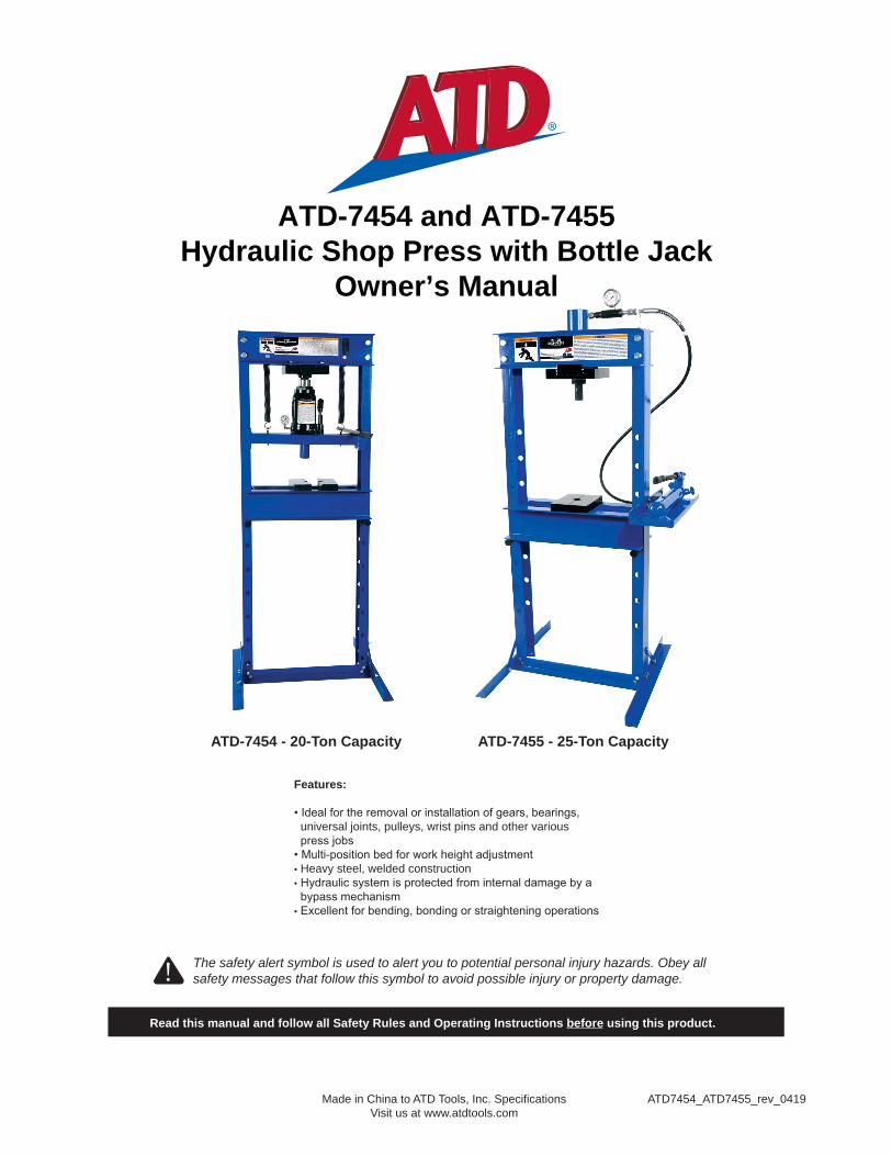
ATD-7454 and ATD-7455Hydraulic Shop Press with Bottle Jack
Owner’s Manual
ATD7454_ATD7455_rev_0419Made in China to ATD Tools, Inc. SpecificationsVisit us at www.atdtools.com
ATD-7454 - 20-Ton Capacity ATD-7455 - 25-Ton Capacity
Features:
universal joints, pulleys, wrist pins and other various
Heavy steel, welded construction
The safety alert symbol is used to alert you to potential personal injury hazards. Obey all safety messages that follow this symbol to avoid possible injury or property damage. !
Read this manual and follow all Safety Rules and Operating Instructions before using this product.
2
SPECIFICATIONSModel Capacity Press Size ( L X W X H ) Max. Working
SpaceMin. Working
Space
20 Ton
25 Ton 28" x 28" x 59"
SAFETY and GENERAL INFORMATIONSave these instructions. For your safety, read, understand, and follow the information provided with and on this product
The owner and operator of this equipment should have an of this product and safe procedures to use. The owner and operator should aware that use and repair of this product may require special and Instructions and safety information should conveyed in the operator's native
use of this is authorized. If any exists as to the safe and proper use of this remove from service immediately.
PRODUCT DESCRIPTION
shops where and is required. Typical applications include installation and removal of alternator and power pump axle transmission seals, and
component. Unlike presses equipped with a separately mounted pump, the power unit on this press can not equipped with a pressure therefore the load must done other means, such as a load cell
r y.
Inspect before each use. Do not use if or parts are noted. Any press that appears in any way, or operates shall removed from service immediately. If any component of this
product has to a load (a load dropped suddenly, unexpectedly upon it), immediately discontinue use until a factory authorized service center. Contact or manufacturer for a list of authorized service
r.
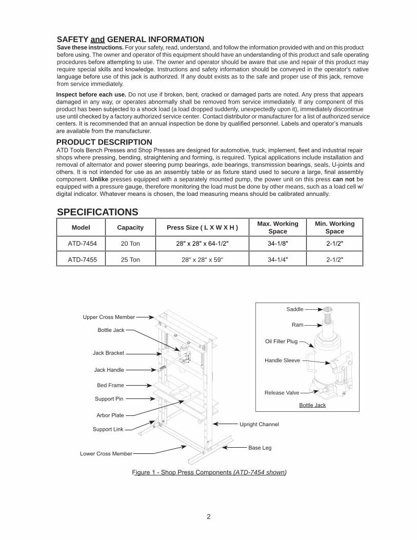
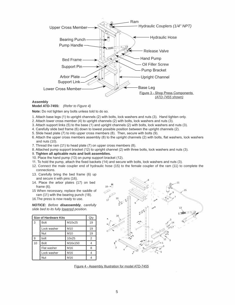
(ATD-7454 shown)
Bed FrameRelease Valve
Handle Sleeve
Ram
Saddle
3
PREPARATIONBefore Use1. V2. Before this product, read the operator's manual completely and familiarize yourself with the
3. To familiarize yourself with operation, (locate and turn the release valve. a. CLOSED release valve position used to extend the ram. This is the ‘ OPEN release valve position used to retract the ram.
This will help release any pressurized air, which may trapped within the reservoir. Ensure the oil level
6. that the pump operates smoothly and that the extension screw will thread easily ATD Tools authorized replacement parts only.
Bleeding / Venting Trapped Air
handle into the handle sleeve; then pump 6 to 8 full This will help release any pressurized air which may
4
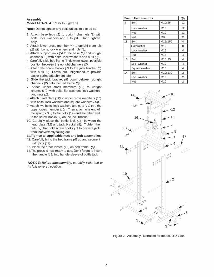
Size of Hardware Kits Qty3 Bolt M10x25 12
M10 12M10 12
9 M8 211 Bolt M16x150 4
M16 8M16 4M16 4
13 Bolt M10x25 4M10 4
Square washer M10 414 Bolt M10x130 2
M10 2M10 2
F
.
Assembly Model ATD-7454: (Refer to Figure 2)
Note:
1. Attach (1) to channels (2) with washers and nuts (3). Hand
only.2. Attach lower cross (4) to channels
(2) (3).3. Attach support (5) to the (1) and
channels (2) with washers and nuts (3) .4. Carefully slide frame (6) down to lowest
(2). 5. Attach the screw (7) to the (8)
with nuts (9). nut to provide r.
6. Slide the (8) down (6).
7. Attach upper cross (10) to channels (2)and nuts (11).
8. Attach head plate (12) to upper cross (10) (13).
9. Attach two washers and nuts (14) thru the upper cross (10). Then attach one end of the (15) to the (14) and the other end
(7)10. Carefully place the (16) the
head plate (12) and (8). T the nuts (9) that hold screw (7) to prevent
11.Tighten all applicable nuts and bolt assemblies.(6) up and secure it
with pins (19). (17) (6).
14.The press is now ready to use. to insert the handle (18)
NOTICE: Before disassembly, carefully slide bed to its fully lowered position.
14
2
3
5
6
17
18
19
7
15
10
11
16
12
89
3
14
13
5
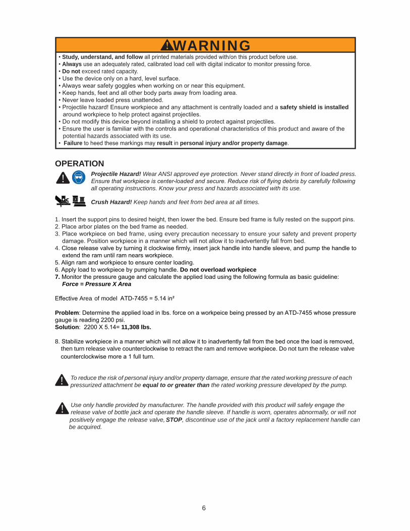
Assembly Model ATD-7455: (Refer to Figure 4)Note:1. y.2. 3.
and nuts (10).7. Thread the ram (18. 9. Tighten all aplicable nuts and bolt assemblies.
12. Connect the male coupler end of hydraulic hose (15) to the female coupler of the ram (11) to complete the connections.
A
Size of Hardware Kits Qty3 Bolt M10x25 19
M10 19M10 19
9 10x25 210 Bolt M16x150 4
M16 8M16 4M16 4
13. Carefully the frame (6) up and secure it with pins (16).
14. the plates (17) on frame (6).
15 When necessary, replace the saddle of ram (1
16.The press is now ready to use.
NOTICE: Before disassembly, carefully slide bed to its fully lowered position.
(ATD-7455 shown)
Bed Frame
Hydraulic Couplers (1/4" NPT)
Hydraulic Hose
Oil Filler Screw
Release Valve
Ram
15
8
4
17
18
6
9
7
3
31
14
3
11
122
5
3
13
16
10
Flat washer
6
!
Study, understand, and followAlways Do not exceed rated capacity.
safety shield is installed
potential hazards associated with its use.Failure result in personal injury and/or property damage.
OPERATIONProjectile Hazard! Wear ANSI approved eye protection. Never stand directly in front of loaded press.
fully following all operating instructions. Know your press and hazards associated with its use.
Crush Hazard! Keep hands and feet from bed area at all times.
1.
3. on frame, every precaution necessary to ensure your safety and prevent property
4.
5. 6. Do not overload workpiece7. Force = Pressure X Area
Area of model
Problem
Solution 11,308 lbs.
8. then turn release valve to retract the ram and remove Do not turn the release valve
! Use only handle provided by manufacturer. The handle provided with this product will safely engage the release valve of bottle jack and operate the handle sleeve. If handle is worn, operates abnormally, or will notpositively engage the release valve, STOP, discontinue use of the jack until a factory replacement handle can be acquired.
To reduce the risk of personal injury and/or property damage, ensure that the rated working pressure of each pressurized attachment be equal to or greater than the rated working pressure developed by the pump.
!
WARNING
7
MAINTENANCEBefore each use, inspect press for Do not use if or otherwise
y
Adding/Changing oil to bottle jack
ATD-7454: Important:
2. With ram fully lowered and pump piston fully depressed, set jac
Note
ATD-7455:1. Depressurize and disconnect hydraulic hose from application.
Note: .4.
screw.
Rust prevention ram and pump piston for of rust on a Clean as needed with a lint free, oil saturated cloth.
Never
How to remove faulty coupler:If ram does not Depressurize pump and hose, then remove the ram from application. Disconnect and replace with new coupler.Important:
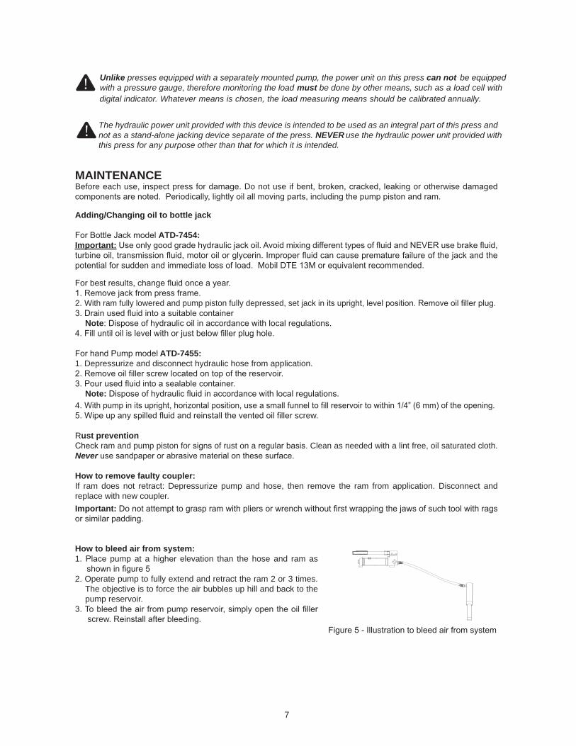
How to bleed air from system:1. pump at a elevation than the hose and ram as
2. Operate pump to fully extend and retract the ram 2 or 3 times. The is to force the air up hill and to the pump reservoir.
screw
! The hydraulic power unit provided with this device is intended to be used as an integral part of this press and not as a stand-alone jacking device separate of the press. NEVER use the hydraulic power unit provided with this press for any purpose other than that for which it is intended.
digital indicator. Whatever means is chosen, the load measuring means should be calibrated annually.
! Unlike presses equipped with a separately mounted pump, the power unit on this press can notwith a pressure gauge, therefore monitoring the load must be done by other means, such as a load cell with
be equipped
REPLACEMENT PARTS:
8
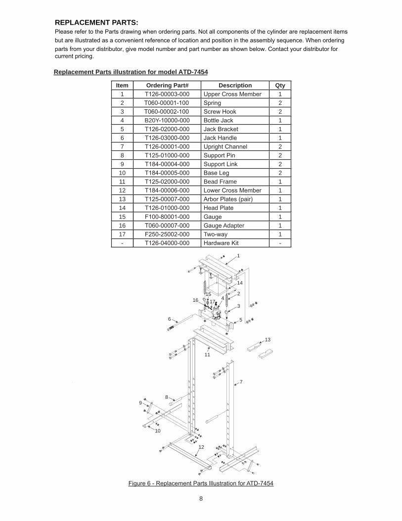
Replacement Parts illustration for model ATD-7454
A
1
14
2
3
5
7
11
10
98
6
13
41615
17
12
Item Ordering Part# Description Qty1 12 23 24 B20Y 15 16 17 28 29 210 211 Bead Frame 112 113 114 115 116 Adapter 117 T 1
9
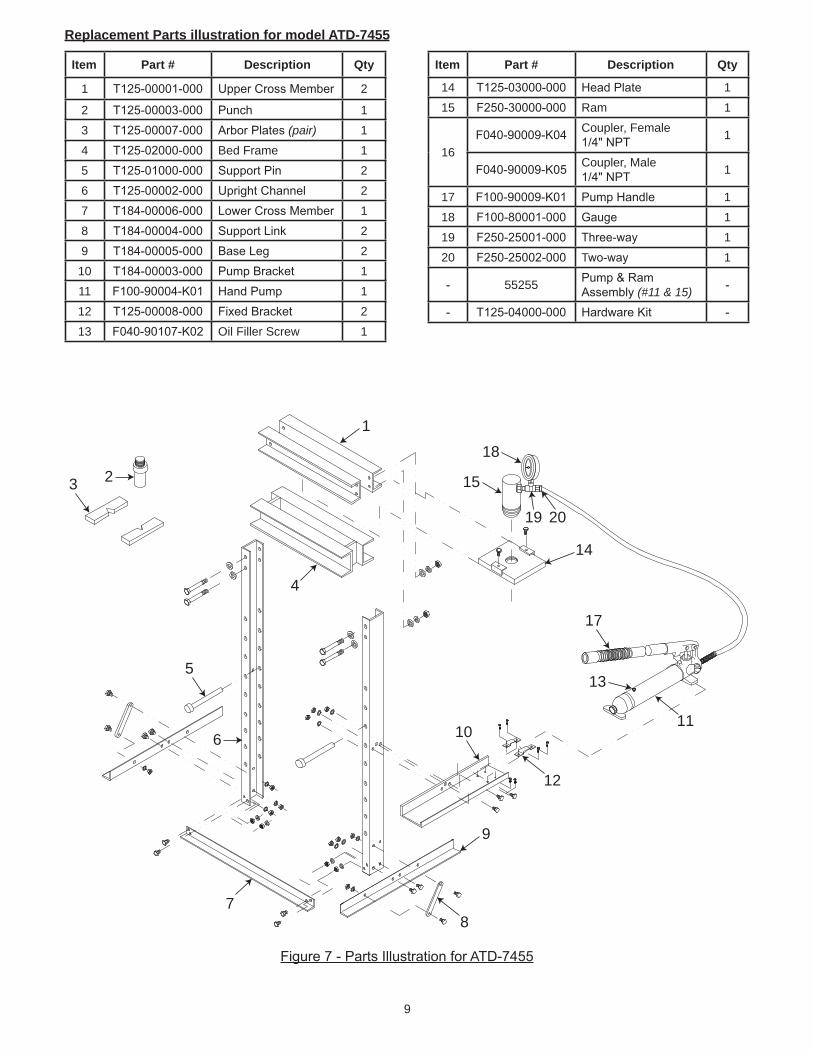
Item Part # Description Qty
1 2
2 13 (pair) 14 Bed Frame 15 26 27 18 29 2
10 111 112 213 Oil Filler Screw 1
A
Replacement Parts illustration for model ATD-7455
Item Part # Description Qty
14 115 Ram 1
16
Coupler, Female 1
Coupler, Male 1
17 118 119 120 T 1
55255 (#11 & 15)
1
7
4
9
12
11
14
8
15
18
19 20
13
6
2
17
10
5
3
10
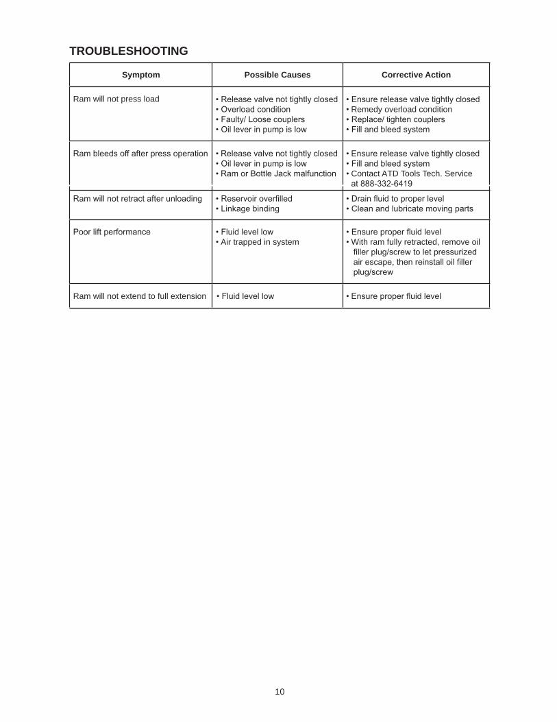
Symptom Possible Causes Corrective Action
Ram will not press load Remedy overload condition
t
Contact ATD Tools Tech. Service
Air trapped in system With ram fully retracted, remove oil
Ram will not extend to full extension
TROUBLESHOOTING
DATE MAINTENANCE PERFORMED
PREVENTATIVE MAINTENANCE RECORD LOG
11
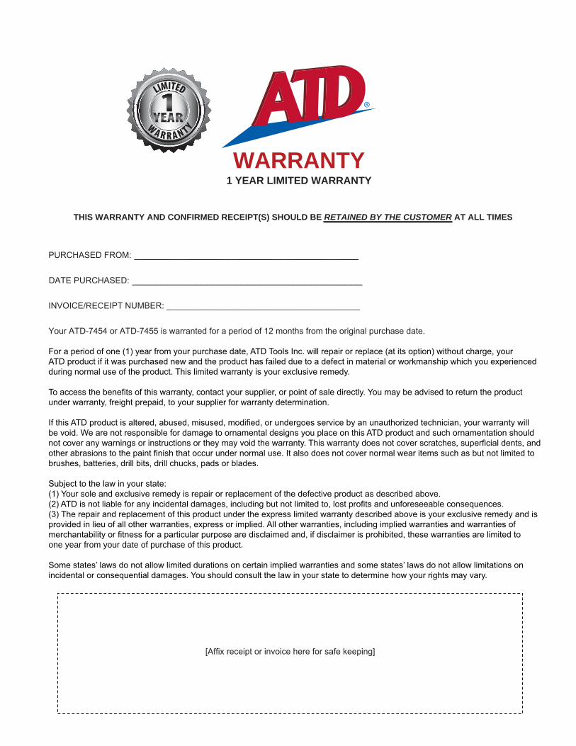
WARRANTY 1 YEAR LIMITED WARRANTY
THIS WARRANTY AND CONFIRMED RECEIPT(S) SHOULD BE RETAINED BY THE CUSTOMER AT ALL TIMES
_______________________________________
________________________________________
RECE
one year from your date of purchase of this product.