attachment “b technical specifications · other fastening devices used to locate or hold the...
TRANSCRIPT

IFB 39-17-18 – Rehabilitation of Wastewater Pump Station No. 24 (Hospital Station)
Attachment “B”
Technical Specifications

CITY OF NORTH MIAMI
TECHNICAL SPECIFICATIONS APPENDICES
REHABILITATION OF WASTEWATER PUMP STATION
NO. 24 (HOSPITAL STATION)
APPENDIX A
PUMP SPECIFICATIONS
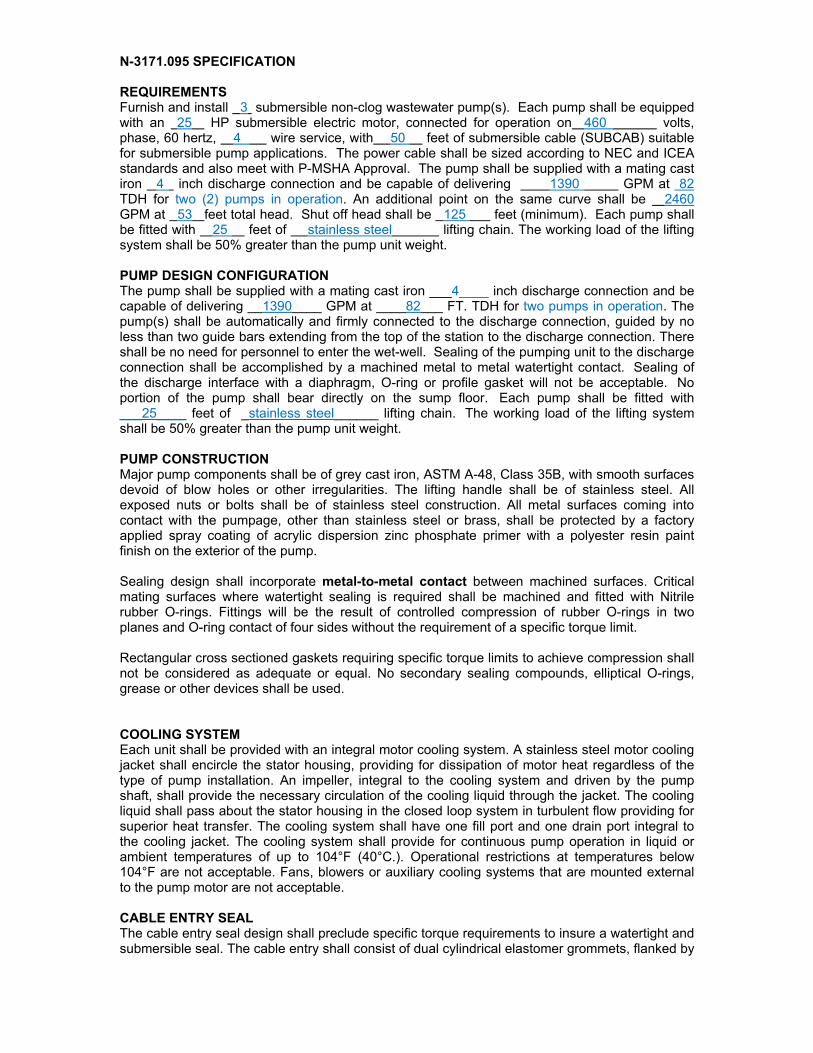
N-3171.095 SPECIFICATION REQUIREMENTS Furnish and install 3 submersible non-clog wastewater pump(s). Each pump shall be equipped with an 25 HP submersible electric motor, connected for operation on 460 volts, phase, 60 hertz, 4 wire service, with 50 feet of submersible cable (SUBCAB) suitable for submersible pump applications. The power cable shall be sized according to NEC and ICEA standards and also meet with P-MSHA Approval. The pump shall be supplied with a mating cast iron 4 inch discharge connection and be capable of delivering 1390 GPM at 82 TDH for two (2) pumps in operation. An additional point on the same curve shall be 2460 GPM at 53 feet total head. Shut off head shall be 125 feet (minimum). Each pump shall be fitted with 25 feet of stainless steel lifting chain. The working load of the lifting system shall be 50% greater than the pump unit weight. PUMP DESIGN CONFIGURATION The pump shall be supplied with a mating cast iron ___4____ inch discharge connection and be capable of delivering __1390____ GPM at ____82___ FT. TDH for two pumps in operation. The pump(s) shall be automatically and firmly connected to the discharge connection, guided by no less than two guide bars extending from the top of the station to the discharge connection. There shall be no need for personnel to enter the wet-well. Sealing of the pumping unit to the discharge connection shall be accomplished by a machined metal to metal watertight contact. Sealing of the discharge interface with a diaphragm, O-ring or profile gasket will not be acceptable. No portion of the pump shall bear directly on the sump floor. Each pump shall be fitted with ___25____ feet of _stainless steel______ lifting chain. The working load of the lifting system shall be 50% greater than the pump unit weight. PUMP CONSTRUCTION Major pump components shall be of grey cast iron, ASTM A-48, Class 35B, with smooth surfaces devoid of blow holes or other irregularities. The lifting handle shall be of stainless steel. All exposed nuts or bolts shall be of stainless steel construction. All metal surfaces coming into contact with the pumpage, other than stainless steel or brass, shall be protected by a factory applied spray coating of acrylic dispersion zinc phosphate primer with a polyester resin paint finish on the exterior of the pump. Sealing design shall incorporate metal-to-metal contact between machined surfaces. Critical mating surfaces where watertight sealing is required shall be machined and fitted with Nitrile rubber O-rings. Fittings will be the result of controlled compression of rubber O-rings in two planes and O-ring contact of four sides without the requirement of a specific torque limit. Rectangular cross sectioned gaskets requiring specific torque limits to achieve compression shall not be considered as adequate or equal. No secondary sealing compounds, elliptical O-rings, grease or other devices shall be used. COOLING SYSTEM Each unit shall be provided with an integral motor cooling system. A stainless steel motor cooling jacket shall encircle the stator housing, providing for dissipation of motor heat regardless of the type of pump installation. An impeller, integral to the cooling system and driven by the pump shaft, shall provide the necessary circulation of the cooling liquid through the jacket. The cooling liquid shall pass about the stator housing in the closed loop system in turbulent flow providing for superior heat transfer. The cooling system shall have one fill port and one drain port integral to the cooling jacket. The cooling system shall provide for continuous pump operation in liquid or ambient temperatures of up to 104°F (40°C.). Operational restrictions at temperatures below 104°F are not acceptable. Fans, blowers or auxiliary cooling systems that are mounted external to the pump motor are not acceptable. CABLE ENTRY SEAL The cable entry seal design shall preclude specific torque requirements to insure a watertight and submersible seal. The cable entry shall consist of dual cylindrical elastomer grommets, flanked by
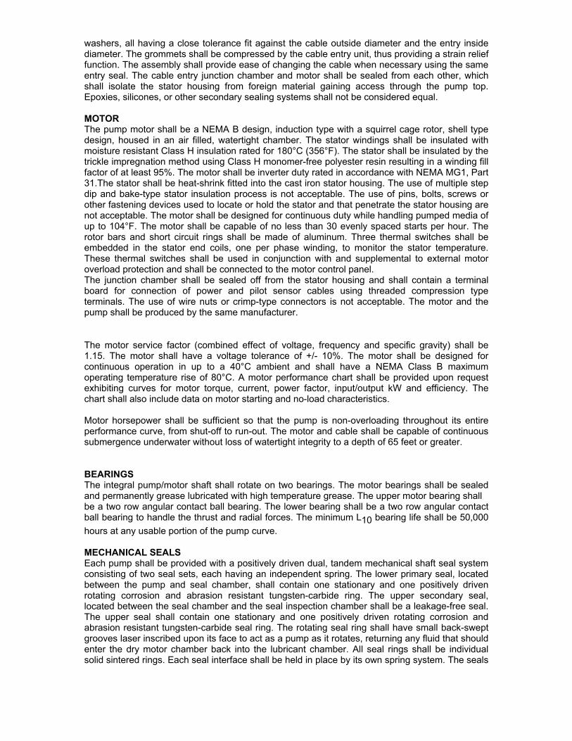
washers, all having a close tolerance fit against the cable outside diameter and the entry inside diameter. The grommets shall be compressed by the cable entry unit, thus providing a strain relief function. The assembly shall provide ease of changing the cable when necessary using the same entry seal. The cable entry junction chamber and motor shall be sealed from each other, which shall isolate the stator housing from foreign material gaining access through the pump top. Epoxies, silicones, or other secondary sealing systems shall not be considered equal. MOTOR The pump motor shall be a NEMA B design, induction type with a squirrel cage rotor, shell type design, housed in an air filled, watertight chamber. The stator windings shall be insulated with moisture resistant Class H insulation rated for 180°C (356°F). The stator shall be insulated by the trickle impregnation method using Class H monomer-free polyester resin resulting in a winding fill factor of at least 95%. The motor shall be inverter duty rated in accordance with NEMA MG1, Part 31.The stator shall be heat-shrink fitted into the cast iron stator housing. The use of multiple step dip and bake-type stator insulation process is not acceptable. The use of pins, bolts, screws or other fastening devices used to locate or hold the stator and that penetrate the stator housing are not acceptable. The motor shall be designed for continuous duty while handling pumped media of up to 104°F. The motor shall be capable of no less than 30 evenly spaced starts per hour. The rotor bars and short circuit rings shall be made of aluminum. Three thermal switches shall be embedded in the stator end coils, one per phase winding, to monitor the stator temperature. These thermal switches shall be used in conjunction with and supplemental to external motor overload protection and shall be connected to the motor control panel. The junction chamber shall be sealed off from the stator housing and shall contain a terminal board for connection of power and pilot sensor cables using threaded compression type terminals. The use of wire nuts or crimp-type connectors is not acceptable. The motor and the pump shall be produced by the same manufacturer.
The motor service factor (combined effect of voltage, frequency and specific gravity) shall be 1.15. The motor shall have a voltage tolerance of +/- 10%. The motor shall be designed for continuous operation in up to a 40°C ambient and shall have a NEMA Class B maximum operating temperature rise of 80°C. A motor performance chart shall be provided upon request exhibiting curves for motor torque, current, power factor, input/output kW and efficiency. The chart shall also include data on motor starting and no-load characteristics. Motor horsepower shall be sufficient so that the pump is non-overloading throughout its entire performance curve, from shut-off to run-out. The motor and cable shall be capable of continuous submergence underwater without loss of watertight integrity to a depth of 65 feet or greater. BEARINGS The integral pump/motor shaft shall rotate on two bearings. The motor bearings shall be sealed and permanently grease lubricated with high temperature grease. The upper motor bearing shall be a two row angular contact ball bearing. The lower bearing shall be a two row angular contact ball bearing to handle the thrust and radial forces. The minimum L10 bearing life shall be 50,000
hours at any usable portion of the pump curve. MECHANICAL SEALS Each pump shall be provided with a positively driven dual, tandem mechanical shaft seal system consisting of two seal sets, each having an independent spring. The lower primary seal, located between the pump and seal chamber, shall contain one stationary and one positively driven rotating corrosion and abrasion resistant tungsten-carbide ring. The upper secondary seal, located between the seal chamber and the seal inspection chamber shall be a leakage-free seal. The upper seal shall contain one stationary and one positively driven rotating corrosion and abrasion resistant tungsten-carbide seal ring. The rotating seal ring shall have small back-swept grooves laser inscribed upon its face to act as a pump as it rotates, returning any fluid that should enter the dry motor chamber back into the lubricant chamber. All seal rings shall be individual solid sintered rings. Each seal interface shall be held in place by its own spring system. The seals

shall not depend upon direction of rotation for sealing. Mounting of the lower seal on the impeller hub is not acceptable. Shaft seals without positively driven rotating members or conventional double mechanical seals containing either a common single or double spring acting between the upper and lower seal faces are not acceptable. The seal springs shall be isolated from the pumped media to prevent materials from packing around them, limiting their performance. Each pump shall be provided with a lubricant chamber for the shaft sealing system. The lubricant chamber shall be designed to prevent overfilling and shall provide capacity for lubricant expansion. The seal lubricant chamber shall have one drain and one inspection plug that are accessible from the exterior of the motor unit. The seal system shall not rely upon the pumped media for lubrication. The area about the exterior of the lower mechanical seal in the cast iron housing shall have cast in an integral concentric spiral groove. This groove shall protect the seals by causing abrasive particulate entering the seal cavity to be forced out away from the seal due to centrifugal action. A separate seal leakage chamber shall be provided so that any leakage that may occur past the upper, secondary mechanical seal will be captured prior to entry into the motor stator housing. Such seal leakage shall not contaminate the motor lower bearing. The leakage chamber shall be equipped with a float type switch that will signal if the chamber should reach 50% capacity. PUMP SHAFT The pump and motor shaft shall be a single piece unit. The pump shaft is an extension of the motor shaft. Shafts using mechanical couplings shall not be acceptable. The shaft shall be stainless steel – ASTM A479 S43100-T. Shaft sleeves will not be acceptable. IMPELLER The impeller shall be of Hard-IronTM (ASTM A-532 (Alloy III A) 25% chrome cast iron), dynamically balanced, semi-open, multi-vane, back swept, screw-shaped, non-clog design. The impeller leading edges shall be mechanically self-cleaned automatically upon each rotation as they pass across a spiral groove located on the volute suction. The leading edges of the impeller shall be hardened to Rc 60 and shall be capable of handling solids, fibrous materials, heavy sludge and other matter normally found in wastewater. The screw shape of the impeller inlet shall provide an inducing effect for the handling of up to 5% sludge and rag-laden wastewater. The impeller to volute clearance shall be readily adjustable by the means of a single trim screw. The impeller shall be locked to the shaft, held by an impeller bolt and shall be coated with alkyd resin primer. VOLUTE / SUCTION COVER The pump volute shall be a single piece grey cast iron, ASTM A-48, Class 35B, non-concentric design with smooth passages of sufficient size to pass any solids that may enter the impeller. Minimum inlet and discharge size shall be as specified. The volute shall have a replaceable suction cover insert ring in which are cast spiral-shaped, sharp-edged groove(s). The spiral groove(s) shall provide trash release pathways and sharp edge(s) across which each impeller vane leading edge shall cross during rotation so to remain unobstructed. The insert ring shall be cast of Hard-IronTM (ASTM A-532 (Alloy III A) 25% chrome cast iron) and provide effective sealing between the multi-vane semi-open impeller and the volute housing. PROTECTION Each pump motor stator shall incorporate three thermal switches, one per stator phase winding and be connected in series, to monitor the temperature of the motor. Should the thermal switches open, the motor shall stop and activate an alarm. A float switch shall be installed in the seal leakage chamber and will activate if leakage into the chamber reaches 50% chamber capacity, signaling the need to schedule an inspection. The thermal switches and float switch shall be connected to a Mini CAS control and status monitoring unit. The Mini CAS unit shall be designed to be mounted in the pump control panel.

EXPLOSION-PROOF Electric Submersible Pumps must be approved by Factory Mutual Research (FM) as Explosion-proof. They must conform to the latest edition of the National Electrical Code (NEC), Articles 500, 501, 502, and 503 requirements as explosion proof and suitable for use in Class I, Division 1, Groups C and D, and dust ignition proof and suitable for use in Class II, Division 1, Groups E, F and G hazardous locations, and suitable for use in Class III, Division 1 hazardous locations. FM approval also meets OSHA (Occupational Safety and Health Administration) requirements.

APPENDIX B
EXPOXYTECH SPECIFICATIONS

Page 1 of 10 revised: May 20, 2016
LIFT STATION AND SIMILAR STRUCTURES REHABILITATION AND LINING
WITH A 100% SOLIDS HYBRID EPOXY COMPOSITE SYSTEM PART 1 - GENERAL 1.1 WORK OF THIS SECTION
A. This section defines the scope of work of the specification which includes executing surface preparation, cleaning, application of specified products, inspection and testing for general repairs and lining of newly installed, existing, and defective specified structures and surfaces by a monolithic application of a high build barrier liner underlayment of epoxy-modified-mortar and a topcoat of high performance, solvent-free UME (Urethane-Modified-Epoxy) hybrid novolac epoxy coating resulting in a UME composite lining system to eliminate infiltration/inflow (I&I), exfiltration, repair voids and deterioration, and provide corrosion protection as a total rehabilitative lining system.
B. Procedures for qualifying and are described herein. In addition to the lining system, different repair methods and procedures are listed in this specification. All structures scheduled for rehabilitation shall be cleaned, prepared, repaired, patched and/or sealed as required prior to the application of the UME composite lining system.
1.2 SCOPE OF WORK
A. The Contactor shall be responsible for furnishing all labor, supervision, products, materials, and equipment required to complete all rehabilitation work and testing in accordance with this Specification.
B. All Sections of this Specification are mutually complimentary and the overall intent is that the Contractor shall provide for everything in his portion of the work required to make a complete and operable job in every respect unless specifically noted otherwise.
C. It is the intent of this Specification to ensure that the work, as completed shall meet all applicable codes, ordinances, rules and regulations of every authority having jurisdiction in the area where the project(s) is located. Failure of the Contractor to point out items that do not meet such requirements does not relieve the Contractor or the Subcontractors of the responsibility of meeting them.
D. All supplies shall be stored and maintained by the Contractor in accordance with manufacturer’s recommendations. Materials shall not be exposed to adverse conditions prior to the work. All materials shall be kept in secured area and away from general public access. The Contractor shall review and maintain all Safety Data Sheets (SDS), product labeling, and technical literature at the project site.
1.3 REFERENCES
A. The latest codes and standards referenced herein and belonging to the following organizations shall be followed: 1. American Society for Testing and Materials (ASTM) 2. National Association of Corrosion Engineers, NACE International (NACE) 3. The Society for Protective Coatings (SSPC) 4. Occupational Safety and Health Administration (OSHA) 5. Resource Conservation and Recovery Act (RCRA) 6. United States Environmental Protection Agency (EPA) 7. Environmental Technology Verification (ETV) 8. International Concrete Repair Institute (ICRI) 9. National Association of Sewer Service Companies (NASSCO) 10. National Sanitation Foundation (NSF) 11. Center for Innovative Grouting Materials and Technology (CIGMAT) 12. American Association of State Highway and Transportation Officials (AASHTO)
1.4 SUBMITTALS
A. Product Data

Page 2 of 10 revised: May 20, 2016
1. Technical data sheets and safety data sheets on each product proposed shall be furnished. The technical data, with quantitative and qualitative values based on ASTM testing results, and/or other 3rd party testing methods shall demonstrate performance conformity with these specifications.
B. Application Data 1. Project specific guidelines and recommendations. 2. Proof of any required federal, state or local permits or licenses necessary for the project. 3. Design details for any ancillary systems and equipment to be used on site for surface preparation,
application and testing. 4. Confined space entry, flow diversion and/or bypass plans shall be presented by Contractor to Owner as
necessary to perform the specified work. 5. Applicator: Company specializing in performing work of this section with minimum one (1) year
documented experience and approved by coating material manufacturer. If spraying, contractor must be certified by manufacturer verifying ownership proper equipment and training.
6. Three (3) recent references of Applicator indicating successful application of coating product(s) of the same or similar material type as specified herein, within lift station environments.
7. Written warranty. i. Materials and labor shall be warranted with bond by the Contractor of applied material systems
per Division 1 General Requirements from the date of final acceptance of the project, once correctly applied by an approved applicator and inspected.
ii. Failure will be deemed to have occurred if the protective system fails to (a) prevent the internal damage or corrosion of the underlying structure due to bacteriological, chemical, gaseous, erosive and abrasive attack. It does not include excessive atypical non-wastewater induced chemical abuse or atypical acts of God which cause structural damage, (b) seal and protect the substrate and environment from contamination by effluent, (c) seal and protect from influent.
iii. Contractor shall, within a reasonable time after receipt of written notice thereof, repair defects in materials or workmanship which may develop during said warranty period, and any damage to other work caused by such defects or the repairing of same, at his own expense and without cost to the Owner.
C. Or Equal Submittal 1. In order to be considered as an equal product, said product will have to meet the minimum physical and
performance properties described herein as measured by the applicable ASTM standards referenced or other 3rd party referenced testing methods. Testing results must be performed and presented in the form of technical data sheets. Said product manufacturer must provide documentation supporting product’s success and history in closed-wastewater-environments for at least ten (10) years.
2. Equal products’ technical specifications/data and material safety data must be submitted to Owner a minimum of three (3) weeks prior to bid date. Samples of raw material must be submitted in order to cover at least one (1) square foot of surface.
3. Written product pre-approval is required to determine if the prospective product may be bid and utilized on this project(s). A product will be rejected as unacceptable should submittal to Owner not be received by the deadline and should the bid package not have enclosed a written approval from the Owner.
PART 2 – PRODUCTS 2.1 ACTIVE LEAK CONTROL
A. Active leak control materials are to be utilized to stop running water, infiltration, and other water stop needs. B. All active leak control materials must be compatible with repair and lining materials. C. Active leak control materials
1. Hydraulic cement i. Quick setting, hydraulic cement compound designed for minor patching, and as a leak stopper
and water plug, which stops running water and/or seepage through concrete. ii. Approved material shall exhibit the following physical properties:
Initial Set Time @ 77F 1-3 minutes

Page 3 of 10 revised: May 20, 2016
Tensile Strength, ASTM C-496 640+ psi Compressive Strength, ASTM C-109
1 day ≥ 1,500 psi 28 days ≥ 5,000 psi
iii. Specified material(s) are listed below:
Epoxytec Mortartec Hydrxx (#RCHY) by Epoxytec (epoxytec.com) 877.GO.EPOXY 954.961.2395 (fax)
2. Chemical grout
i. Chemical grout material used for grouting active leaks shall be injection hydrophobic polyurethane or equal.
ii. While being injected, the chemical sealant must be able to react/perform in the presence of water. iii. The cured material must withstand submergence in water, without degradation. iv. The resultant sealant (grout) formation must be impervious to water penetration. v. The final sealant must withstand freeze-thaw and wet-dry cycles without causing adverse changes
to the sealant. vi. The final sealant formation must not be biodegradable.
vii. Chemical grouting material final cure must not exceed one (1) hour. viii. Chemical grouting material must be compatible to other specified repair and liner materials.
2.2 CONCRETE REPAIR
A. Concrete repair methods include isolated, sectional, and fully restorative methods including brick, concrete, and other masonry filling, patching, termination of materials, seams, anchors, and rebuilding based on various conditions beyond 1/4-inch (1/4”) of profile loss or deteriorated from peak to valley, in order to repair imperfections that adversely affects flow, would compromise the structure and liner in the future, and to restore the structure to a profile accepting to the lining system. Less than 1/2-inch (1/2”) of profile loss or deterioration will be restored during the 1st part of the lining system and therefore is not addressed in this section.
B. Concrete patching and rebuilding 1. Concrete patching repair shall be performed for any spot repairs, filling or repairs of deep spalls, voids,
gaps, bugholes/holes, and/or crevasses beyond 1/2-inch (1/2”) of profile loss or deteriorated from peak to valley.
2. Rebuild isolated structures, inverts, benches and/or troughs, or other flow structures requiring build-up and/or rebuild in order to provide smooth flow transition waterway with no distortion of flow or connections.
3. Materials i. The material is early-high strength, high build, sewer grade silica fume, fiber reinforced,
industrial-grade modified mortar exhibiting the following minimum properties:
Flexural Strength, ASTM C-293 (28 days) ≥ 950 psi Initial Cure < 24 hours Tensile Strength, ASTM C-496 ≥ 300 psi Bond Strength, ASTM C-882 (mod- 7 days) ≥ 800 psi Shrinkage, ASTM C-596 < 0.05% Freeze/Thaw, ASTM C666 100 cycles, no damage
ii. Specified material(s) are listed below:
Epoxytec Mortartec (#RCM01,02, RCME1, RCHY) by Epoxytec (epoxytec.com) 877.GO.EPOXY 954.961.2395 (fax)
C. Exposed reinforcing bars

Page 4 of 10 revised: May 20, 2016
1. Exposed reinforcing bars must be treated with rust inhibiting primer, and encapsulated/patched with high density mortar.
2. Materials i. Rust inhibiting primer must be epoxy-based, rust inhibiting primer designed for rapid curing, and
for steel applications. ii. High density mortar patching will consist of any of the specified repair mortars within this
section. iii. Specified material(s) are listed below:
Epoxytec A1 Primecoat (#MP1R) by Epoxytec (epoxytec.com) 877.GO.EPOXY 954.961.2395 (fax)
D. Joint sealing, terminations, and specialty barrier build/coating 1. Areas requiring a structural-grade caulk, seal, joint connection, tapping, tie-in, and/or sectional lining
solution for edge terminations and/or high flow/logistically challenging areas that require a moisture tolerant setting hydrostatic barrier solution will utilize a polymer epoxy paste.
2. Polymer paste solution will also be utilized for areas requiring a rapid setting lining solution where logistical challenges cannot be overcome. The solutions can be utilized as a repair material and/or an alternative liner to tie-into the specified lining system.
3. Polymer pastes must be specific and proven for the application, and may be executed after the UME composite lining system’s hybrid epoxy top coat is applied, and therefore compatible with the UME topcoat.
4. Materials i. Polymer paste must exhibit the following features:
a. The polymer epoxy paste must be 100% solid, no VOCs. b. The polymer epoxy paste must be self-priming, requiring no primer. c. The polymer epoxy paste must be moisture tolerant up 100% and fully cure underwater. d. The polymer epoxy paste must be able to be applied by trowel (hand-applied) in order to
mobilize and apply in limited access areas. e. The polymer epoxy paste must hang with vertical and overhead thickness capability of
1/16 inch to 1/2 inch in one pass without sag. f. The polymer epoxy paste must have an indefinite recoat window without preparation for
simple repair requirements. ii. Approved material shall exhibit the following physical properties:
a. Type hybrid polymer (epoxy/epoxide) b. Solids by Volume ASTM D2697 100% c. Adhesion Strength (concrete/brick) CIGMAT CT-2/3 substrate failure d. Water Absorption ASTM D1653 < 0.1 g/sq.m. e. Acid Exposure (pH 1, H2SO4) CIGMAT CT-1 passed f. Tensile Strength ASTM D638 5,500+ psi g. Flexural Modulus ASTM D790 500,000+ psi h. Flexural Strength ASTM D790 4,000+ psi i. Compressive Strength ASTM D695 16,000+ psi j. Complete Cure 18 hours (77F)
5. Specified material(s) are listed below: Epoxytec CPP #RC3 (and/or CPP Gel #C311) by Epoxytec (epoxytec.com) 877.GO.EPOXY 954.961.2395 (fax)
2.3 LINING
A. General 1. It is the intent of this specification is to provide for the waterproofing, sealing, structural enhancement
and corrosion protection of existing or newly installed structures and similar underground structures by the safe, quick and economical application of a composite created from a uniform and densely compacted
Page 5 of 10 revised: May 20, 2016
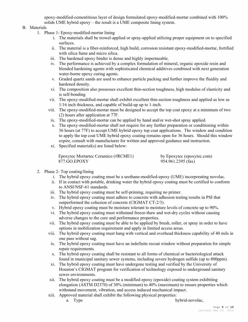
epoxy-modified-cementitious layer of design formulated epoxy-modified-mortar combined with 100% solids UME hybrid epoxy – the result is a UME composite lining system.
B. Materials 1. Phase 1- Epoxy-modified-mortar lining
i. The materials shall be trowel-applied or spray-applied utilizing proper equipment on to specified surfaces.
ii. The material is a fiber-reinforced, high build, corrosion resistant epoxy-modified-mortar, fortified with silica fume and micro silica.
iii. The hardened epoxy binder is dense and highly impermeable. iv. The performance is achieved by a complex formulation of mineral, organic epoxide resin and
blended hardening agents with sophisticated chemical additives combined with next generation water-borne epoxy curing agents.
v. Graded quartz sands are used to enhance particle packing and further improve the fluidity and hardened density.
vi. The composition also possesses excellent thin-section toughness, high modulus of elasticity and is self-bonding
vii. The epoxy-modified-mortar shall exhibit excellent thin-section toughness and applied as low as 1/16 inch thickness, and capable of build-up up to 1-inch.
viii. The epoxy-modified-mortar must be designed to accept the top coat epoxy at a minimum of two (2) hours after application at 77F.
ix. The epoxy-modified-mortar can be applied by hand and/or wet-shot spray applied. x. The epoxy-modified-mortar shall not require for any further preparation or conditioning within
36 hours (at 77F) to accept UME hybrid epoxy top coat applications. The window and condition to apply the top coat UME hybrid epoxy coating remains open for 36 hours. Should this window expire, consult with manufacturer for written and approved guidance and instruction.
xi. Specified material(s) are listed below:
Epoxytec Mortartec Ceramico (#RCME1) by Epoxytec (epoxytec.com) 877.GO.EPOXY 954.961.2395 (fax)
2. Phase 2- Top coating/lining i. The hybrid epoxy coating must be a urethane-modified-epoxy (UME) incorporating novolac.
ii. If in contact with potable, drinking water the hybrid epoxy coating must be certified to conform to ANSI/NSF-61 standards.
iii. The hybrid epoxy coating must be self-priming, requiring no primer. iv. The hybrid epoxy coating must adhere to concrete with adhesion testing results in PSI that
outperformed the cohesion of concrete (CIGMAT CT-2/3). v. Hybrid epoxy coating must be moisture tolerant to moisture levels of concrete up to 90%.
vi. The hybrid epoxy coating must withstand freeze-thaw and wet-dry cycles without causing adverse changes to the cure and performance properties.
vii. The hybrid epoxy coating must be able to be applied by brush, roller, or spray in order to have options in mobilization requirement and apply in limited access areas.
viii. The hybrid epoxy coating must hang with vertical and overhead thickness capability of 40 mils in one pass without sag.
ix. The hybrid epoxy coating must have an indefinite recoat window without preparation for simple repair requirements.
x. The hybrid epoxy coating shall be resistant to all forms of chemical or bacteriological attack found in municipal sanitary sewer systems, including severe hydrogen sulfide (up to 800ppm).
xi. The hybrid epoxy coating must have undergone testing and verified by the University of Houston’s CIGMAT program for verification of technology exposed to underground sanitary sewer environments.
xii. The hybrid epoxy coating must be a modified epoxy (epoxide) coating system exhibiting elongation (ASTM D2370) of 30% (minimum) to 40% (maximum) to ensure properties which withstand movement, vibration, and access induced mechanical impact.
xiii. Approved material shall exhibit the following physical properties: a. Type hybrid-novolac,

Page 6 of 10 revised: May 20, 2016
urethane-modified-epoxy b. Solids by Volume ASTM D2697 100% c. Solvent (VOC) ASTM D3960 none d. Adhesion Strength (concrete, dry) CIGMAT CT-2/3 substrate failure e. Adhesion Strength (brick, wet) CIGMAT CT-2/3 substrate failure f. Adhesion Strength (steel) ASTM D4541 1,500+ psi g. Water Absorption ASTM D1653 < 0.1 g/sq.m. h. Acid Exposure (pH 1, H2SO4) CIGMAT CT-1 passed i. Tensile Strength ASTM D638 5,500+ psi j. Flexural Modulus ASTM D790 55,000+ psi k. Flexural Strength ASTM D790 8,000+ psi l. Compressive Strength ASTM D695 7,000+ psi m. Elongation ASTM D2370 30-40% n. Complete Cure 18 hours (77F)
xiv. Specified material(s) are listed below:
Epoxytec Uroflex #UME38 by Epoxytec (epoxytec.com) (or Epoxytec Uroflex 61 #WUME for potable water ) 877.GO.EPOXY
954.961.2395 (fax)
PART 3 – EXECUTION 3.1 GENERAL
A. All work shall be in strict accordance with the specifications and recommendation including application of all products as required and in accordance with manufacturer’s directions.
B. Contractor shall conform to all local, state and federal regulations including those set forth by OSHA, RCRA and the EPA and any other applicable authorities.
C. Products are to be kept dry, in a climate controlled environment, protected from weather and stored under cover. Products are to be stored and handled according to their safety data sheets. When freezing temperatures are expected in the area, the Contractor shall take measures to keep applied materials warm (as per manufacturer’s guidelines) and provide the required heat in the structure before repair work is started.
D. Any invert(s), channels, drains, or other openings shall be covered during construction operations to prevent loose materials from collection.
E. Bypassing and/or blocking of flow shall be done only with prior approval of the Owner. Contractor shall be responsible for transporting or pumping water to maintain operation of any flow, treatment, collection or distribution system while repairs or lining to structures are made.
F. The Owner shall supply water necessary for the project to the Contractor at no cost, from locations indicated by Owner prior to the start of the project. Contractor shall be responsible for transporting the water.
G. It shall be the contactor’s responsibility to provide traffic control required by the particular location and/or jurisdiction.
H. Use approved equipment designed, recommended and/or manufactured by the material supplier specifically for the application of all materials.
I. Applicator shall initiate and enforce quality control procedures consistent with applicable ICRI, NACE, and/or SSPC standards and the repair/coating manufacturer's recommendations.
J. Examination a. Examine surface to receive rehabilitation prior to applying any materials. Notify Owners in writing if
surfaces are not acceptable for rehabilitation and/or lining. b. All structures to be repaired and coated shall be readily accessible to the Applicator. c. Any active flows shall be dammed, plugged or bypassed as required to ensure that the liquid flow is
maintained below the surfaces to be coated and that concrete to be coated has not reached moisture levels surpassing 90%. Flows should be totally plugged and/or diverted when coating any invert. All extraneous flows into the structures at or above the area coated shall be plugged and/or diverted until the structural epoxy coating has set hard to the touch.

Page 7 of 10 revised: May 20, 2016
d. Temperature of the surface to be coated must be maintained between 65F and 110F during application. Prior to and during application, care should be taken to avoid exposure of direct sunlight or other intense heat source to the structure being coated. Specified surfaces should be shielded to avoid exposure of direct sunlight or other intense heat source. Where varying surface temperatures do exist, coating installation should be scheduled when the temperature is falling versus rising.
e. New Portland cement concrete structures shall have endured a minimum of 28 days since installation, prior to commencing epoxy structural coating installation.
f. Prior to commencing surface preparation, Contractor shall inspect all surfaces specified to receive the coating and notify Owner, of any noticeable disparity in the site, structure or surfaces which may interfere with the work, use of materials or procedures as specified herein.
3.2 CLEANING AND PREPARATION OF SUBSTRATE
A. Surface preparation must be achieved immediately prior to utilizing any repair material and/or coatings, re-inspection and/or subsequent surface preparation may need to be repeated should conditions change after initial preparation.
B. All receiving surfaces shall be thoroughly cleaned and made free of all foreign materials including dirt, grit, roots, grease, sludge and all debris or material that may be attached to the substrate.
C. The objective of surface preparation is to produce a surface that is suitable for application and adhesion of the specified protective coating system and repair products.
1. Protrusions such as from burrs, sharp edges, fins, and concrete spatter shall be removed during surface preparation.
2. Voids and other defects that are at or near the surface shall be exposed during surface preparation. 3. All concrete that is not sound shall be removed so that only sound concrete remains.
D. Surface preparation must achieve a clean and sound substrate in accordance with SSPC-SP13/NACE No. 6 “Surface Preparation of Concrete.”
1. High pressure water cleaning or waterjetting, and/or pre-approved dry or wet abrasive blasting may be necessary in order to achieve acceptable surface preparation free of all foreign material, laitance, oils, grease, incompatible existing coatings, waxes, form release, curing compounds, efflorescence, sealers, salts, and/or other contaminants.
2. An ICRI profile of CSP 3 or higher shall be achieved. 3. For existing structures, surface preparation shall yield a pH of 7 or higher. 4. No surface water or active leaks are to be present. 5. When grease and oil are present within the structure, an approved detergent or degreaser may be used
integrally with the high pressure cleaning water if conditions dictate. E. All materials resulting from the cleaning shall be caught at the base of each structure and removed prior to
applying specified products. F. All loose or defective concrete, mortar, brick, grout, ledges, steps and protruding ledges shall be removed to
provide an accessible and uniformed surface prior to application of materials. 3.3 ACTIVE LEAK CONTROL PROCEDURE
A. Execution 1. When leaks are not readily identifiable upon cleaning operation, use blowers to dry interior for positive
identification of leaks and weeping areas. 2. Hydraulic cement
i. The work consists of hand applying a dry quick-setting cementitious mix designed to instantly stop running water or seepage in all types of concrete and concrete structures. The certified applicator shall apply material in accordance with manufacturers’ recommendations.
ii. The area to be repaired must be clean and free of all debris. iii. Proper applications should not require any special mixing of product or special curing
requirements after application. 3. Chemical grout
i. Application of materials shall be by injection method only. ii. Mixing and handling of all the chemical grout materials shall be in strict accordance with
manufacturer’s recommendations.

Page 8 of 10 revised: May 20, 2016
iii. All excess chemical grout must be removed from the surface via mechanical grinding means and top patched with Hydraulic cement.
3.4 CONCRETE REPAIR METHODS
A. All loose, cracked and corroded materials shall be removed from the area, exposing a sound substrate. B. The materials shall be formed, trowel-applied, or shotcrete sprayed utilizing proper equipment on to specified
surfaces. Follow instructions as published by the material manufacturer. If spraying, consult manufacturer for proper instruction and material version.
C. Concrete patching and rebuilding 1. Execution
i. Once cured, and before applying any lining system materials, refer to material specifications for post-cure preparation and readiness instructions. Follow mixing, application and handling instructions as written per materials product technical data sheets and SDS.
ii. Apply materials and allow proper curing times prior to coating/lining. D. Exposed reinforcing bars
1. Execution i. Prepare and clean via SSPC-SP 2 or 3 exposed reinforcing bars then clean with solvent (SSPC
SP-1). ii. Treat with an epoxy-based, rapid-setting, rust inhibiting primer.
iii. Allow primer to cure. iv. Patch with concrete patching materials as specified in “Concrete patching and rebuilding”
section. Follow product and manufacturer execution specifications accordingly. E. Joint sealing, terminations, and specialty barrier build/coating
1. Execution i. Polymer pastes must be specific and proven for the application, and may be executed after the
UME composite lining system’s hybrid epoxy top coat is applied, and therefore compatible with the UME topcoat.
ii. Prepared all surfaces/substrates as previously specified. iii. Follow epoxy manufacturer published guidelines. iv. Apply material as needed within thickness ranges of 1/8 inch to 1/2 inch per pass. v. Dry heat may be applied to material to force cure, for rapid setting requirements as needed
(consult with manufacturer for proper recommendations). 3.5 LINING METHODS AND PROCEDURES
A. This specification establishes the minimum standard method of application for sealed corrosion protection for
existing and newly installed structures. B. The system is two stages. The high performance epoxy-modified-mortar liner is first applied onto the interior
substrate prior to coating. The material will create a high bond strength layer of protection to the repairs and substrate, minimize the occurrence of outgassing, minimize as a barrier to moisture vapor transmission (MVT) and hydrostatic pressure, and be a failsafe as a part of the first layer to seal I&I and chemical attack. The UME composite lining system is then completed with the application of a 100% solids UME hybrid epoxy. The UME composite lining system will be installed on all specified surfaces in order to seal and protect.
C. All structures to be lined and coated shall be readily accessible to the Applicator. D. Any active flows shall be dammed, plugged or bypassed as required to ensure that the liquid flow is maintained
below the surfaces to be lined and coated and that substrate to be coated has not reached moisture levels surpassing 60%. Flows should be plugged and/or diverted when lining any invert or channel. All extraneous flows into the structures at or above the area lined shall be plugged and/or diverted until the all materials fully cure.
E. Prior to commencing any application procedures, Contractor shall inspect all surfaces specified to receive the coating and notify Owner, of any noticeable disparity in the site, structure or surfaces which may interfere with the work, use of materials or procedures as specified herein. Application procedures shall conform to the recommendations of the lining manufacturer, including material handling, mixing, safety, and application equipment.
F. Phase 1- Epoxy-modified-mortar lining

Page 9 of 10 revised: May 20, 2016
1. This section establishes the minimum standard for material and method of application for the high performance design formulated epoxy-modified-mortar liner part of the system (Phase 1 of 2). The high performance epoxy-modified-mortar liner is first applied onto the specified interior surfaces, and depending on existing condition may be applied in one application or in successive applications. The material can offer applicators resurfacing and lining in-one-shot on existing structures, from low build to high build by hand-application or shotcrete applied.
2. The materials shall be trowel-applied or spray-applied utilizing proper equipment on to specified surfaces. The material thickness is determined based on bridging and uniformly covering peaks and irregularities resulting from deteriorated concrete, spalls, cracks, bugholes in order to achieve an acceptable profile for the UME (Urethane-Modified-Epoxy) hybrid epoxy composite system to be applied.
i. Thickness is further determined based on depth of peak to valley of voids, exposed aggregate, and returning surfaces to an acceptable profile.
ii. Minimum and maximum thickness shall range between 1/4 inch and 1/2 inch (1/4” – 1/2”) when applied directly to original substrate. For areas which were rebuilt, or for newly installed concrete structures, thicknesses shall be between 1/16 inch to 1/8 inch (1/16” – 1/8”).
iii. Execution a. Follow mixing, application and handling instructions as written per materials product
technical data sheets and SDS. b. The mortar kits come pre-proportioned, for hand applications- use full kits as supplied,
no do not any extra water. c. For spray applications, water may be added, but limited, as specified by the
Manufacturer. d. When mixed, a paste-like material will develop which may be troweled, sprayed, cast,
pumped or gravity-flowed applied. e. This mortar will harden quickly without any need for special curing. Therefore, execute
finishing work by trowel immediately after applying or disbursing onto the substrate. f. Either commence spraying or hand applying. g. The epoxy-modified-mortar shall be applied at a 1/4 inch minimum, and 1/2 inch
maximum (1/4” – 1/2”) for existing infrastructure. And between 1/16 inch and 1/8 inch (1/16” – 1/8”) for newly installed structures.
h. Finish with trowel. i. Allow at least two (2) hours (77F) to cure, minimum, before applying the specified
hybrid epoxy coating, but do not exceed thirty-six (36) hours. G. Phase 2- Top coating/lining
1. This section establishes the minimum standard for material and method of application for the second part (Phase 2 of 2) of the composite lining system- the UME hybrid epoxy top coat.
2. The UME epoxy top coat completes the UME composite lining system, and deliver a sealed, ultra- high novolac-based epoxy resistant liner to protect from high levels of H2S and sulfuric by-products all the underlying materials and infrastructure.
3. Execution i. Once the epoxy-modified-mortar liner coating window opens (between 2 – 36 hours @ 77F),
proceed with the application of the hybrid epoxy coating. ii. If spraying, the spray equipment shall be specifically designed to accurately ratio and apply the
specified hybrid epoxy coating materials and shall be regularly maintained and in proper working order.
iii. Top coating or additional coats of the hybrid epoxy coating should occur as soon as the prior coat becomes tacky to tack-free, but no later than the recoat window for the specified material(s). Additional surface preparation procedures will be required if this recoat window is exceeded.
iv. Follow all published and manufacturer recommended application methods. Properly mix and apply materials to all specified surfaces.
v. Application shall be applied in two (2) coats, at a minimum of 20 mils DFT per coat, to cover all specified surfaces to a minimum total DFT of 40 mils.
vi. Return-to-service for full immersion is 24 hours @ 77F. For potable drinking water environments, the return-to-service is 72 hours.

Page 10 of 10 revised: May 20, 2016
3.6 QUALITY ASSURANCE AND ACCEPTANCE
A. Surface preparation inspection must take place prior to proceeding to material applications. Applicator must record pH level, record moisture content, abrasive media type and/or preparation methods, and ICRI conditions and submit to coating manufacturer’s representative or designated inspector.
B. During application, Applicator shall regularly perform and record epoxy coating thickness readings with a wet film thickness gage, such as those meeting ASTM D4414 - Standard Practice for Measurement of Wet Film Thickness of Organic Coatings by Notched Gages, to ensure uniform thickness during application or other similar measuring probe.
C. Applicator shall perform holiday detection on all surfaces coated with the UME hybrid epoxy coating in the presence of the coating manufacturer’s representative or designated inspector. After the UME epoxy coating has set hard to the touch, surfaces shall first be dried, an induced holiday shall then be made on to the coated concrete surface and shall serve to determine the minimum/maximum voltage to be used to test the coating for holidays at that particular area. The spark tester shall be initially set at 100 volts per 1 mil (25 microns) of film thickness applied but may be adjusted as necessary to detect the induced holiday (refer to NACE RPO188-99). All detected holidays shall be marked by the coating manufacturer’s approved marking methods and repaired by abrading the coating surface with grit disk paper or other hand tooling method. After abrading and cleaning, additional epoxy coating material can be hand applied to the repair area. All touch-up/repair procedures shall follow the coating manufacturer's recommendations.
D. A final visual inspection shall be made by the Applicator, coating manufacturer’s representative or designated inspector. Any deficiencies in the finished coating shall be marked and repaired by Applicator according to the procedures set forth herein.
END OF SECTION

APPENDIX C
GEOTECHNICAL REPORT