attrition of material during cutter suction dredging and ......attrition, cutterhead, hydraulic...
TRANSCRIPT
Attrition of material during cutter suction dredging and pipeline transport: a summary
D. Barber, B. O’Dowd and M. Lee
HRPP561 1
Attrition of material during cutter suction dredging and pipeline transport: a summary D. Barber1, B. O’Dowd1 and M. Lee1
1 HR Wallingford Ltd, Howbery Park, Wallingford, Oxfordshire OX10 8BA, United Kingdom
Published in the proceedings of CEDA Dredging Days 2012, 12-13 December, Abu Dhabi, United Arab Emirates
Abstract In the dredging industry, it is advantageous to have advanced knowledge of the expected particle size distribution (PSD) of material that has been subject to dredging processes. During dredging, the removal and transportation of material result in it undergoing significant physical changes.
This paper first considers geotechnical, hydraulic and mechanical processes that influence the PSD of a material dredged by cutter suction dredger (CSD), and discusses the attrition during hydraulic transport through pipelines and pumps. When cutting in-situ material, the failure mechanism for intact material varies with material type e.g. for rock cutting the ductility / brittleness of the material is key. During hydraulic transport, particle behaviour and attrition varies primarily according to particle size, from fines undergoing sustained suspension as a dense carrier-fluid to the rolling bed of rock chips or clay balls. To some degree, the attrition follows a decay behaviour (by mass lost) and reduces the solids-effect, and it is generally most prevalent in centrifugal pumps where the destructive forces are greatest.
The second part of the paper discusses existing laboratory tests and their ability to simulate processes of attrition. Promising tests fall into three categories: cutterhead scale-models (for simulating material cutting and entrainment into the suction pipe); drum tests (for simulating pipeline attrition); and centrifugal pipeline-loop tests (for reproducing hydraulic pipeline transport). No single laboratory test provides a comprehensive approach to replicating attrition of material undergoing dredging, though each category of test showed unique advantages and disadvantages when considering practicality, scaling and process similitude.
Keywords
Attrition, cutterhead, hydraulic transport, failure mechanism, scale modelling
1. Introduction Early in the life cycle of a dredging project, it is advantageous to know how the particle size distribution (PSD) of dredged material varies because of the excavation, transport and deposition processes. Predicting the effects of these processes can aid early planning and decision-making that may be key to the project’s success.
Attrition of material during cutter suction dredging and pipeline transport: a summary
D. Barber, B. O’Dowd and M. Lee
HRPP561 2
During dredging, the processes of removal and transport can cause the bed materials to undergo significant physical changes. These changes are influenced by: the in-situ geotechnical properties of the material; the equipment / plant used for the excavation and transport; and the dredging methodology. This paper considers the changes that bed materials undergo when dredged using a cutter suction dredger (CSD), from attrition at the cutterhead to pumping and hydraulic transport. Also addressed is simulation of such processes using laboratory tests and their perceived benefits and limitations.
2. Physical processes Today’s commercial cutter suction dredgers come in a variety of sizes with the largest having a total installed capacity of 20,000 to 28,000 kW, cutterhead diameters in excess of 2.5 m, and a crew capacity of up to fifty people. Regardless of dredger size, the acts of cutting and transporting material can be broken down into a sequence of mechanical and hydraulic processes. This Section considers the passage of the dredged material, from excavation at the seabed to discharge at the pipe outfall.
2.1. At the cutterhead During the removal procedure, the first point of contact with the in-situ material is at the cutterhead, where the following influences occur:
Mechanical influences. These include: the swing speed of the ladder; the rotational speed of the cutterhead; the direction of rotation of the cutterhead relative to the face; the shape of the cutterhead and teeth; spud operation; and the entry angle of the cutterhead / tooth relative to the material face.
Hydraulic influences. These include: the flow / turbulence generated by the rotation of the cutterhead and the swinging of the ladder; and the suction generated by the dredge pump.
Geotechnical / geological influences. These include (where applicable for different material types) parameters such as: the unconfined compressive strength (UCS) of the material; the discontinuity spacing; the ductility / brittleness of the material; and its plasticity.
These combined influences lead to complex behaviour at the cutterhead. Such behaviour is studied theoretically by considering the influences individually and / or simplifying them; for example, the development of cutting theory typically considered actions of a single cuttertooth in order to understand the forces required to remove material.
The force exerted at the tooth is a result of the combined forces due to: the rotation of the cutterhead; the self-weight and swing of the ladder; and the rear winch or spud movement. Vlasblom (2005) expressed this force as the specific energy (excavation energy required per unit volume) and used an empirical factor to represent geotechnical parameters. Miedema (2009, 2010) further developed this theory by relating specific geotechnical properties to the cutter force required.
2.1.1. Failure modes
The advancement of cutting theory has aided understanding of material break up, the interaction of the cutterhead with material types, and the failure modes associated with different material types. This Section discusses these failure modes and their effect on attrition of granular soil, rock and clay.
Attrition of material during cutter suction dredging and pipeline transport: a summary
D. Barber, B. O’Dowd and M. Lee
HRPP561 3
Granular material
For non-cohesive granular materials, such as sand, the cutting process is a high-speed shearing process (Miedema, 2009). The advancing cuttertooth generates shear stresses that cause dilation of the pore volume, increasing grain stresses and the mobilisation of the sediment. With increasing grain size, such as gravels, the angularity and grain shape become more critical as the sliding resistance between particles increases considerably (Bray et al., 1997). Attrition and PSD development of granular material at the cutterhead is not widely discussed in literature; this may well be because the specific energy required to dredge such material is relatively low (150-350 kPa) and therefore insufficient to cause significant attrition.
Rock
A heterogeneous crushing zone occurs at the tooth-rock interface where nearly all of the cutting energy is expended. Material in this zone crushes entirely and then transfers the load to the supporting intact material, causing micro-cracks to spread leading to failure of the chip. These cracks will naturally exploit in-situ fractures and weaknesses. Each tooth cut produces chips of varying size according to small-scale variations in the character of the rock and the applied cutting forces. Such chips form the bulk of the cut volume and are accompanied by a smaller volume of fine material from the crush zone. Geking (1987) suggested using ratios of the UCS over the Brazilian Tensile Strength (BTS) to predict failure modes of intact materials, see Table 1.
Table 1: Ductility of intact material by the Unconfined Compressive Strength and Brazilian Tensile Strength ratio
UCS / BTS Failure Mode
< 9 Ductile
9 – 15 Transitional
> 15 Brittle
Source: Geking, 1987
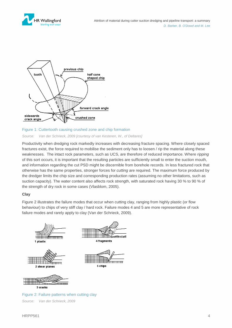
Brittle failure involves a shallow sideward crack angle (see Figure 1), and the chip is generally bulky and wide. As the tooth advances, this chip separates from the rock mass (alike failure mode 5 in Figure 2). Ductile failure produces a much smaller chip with a steep sideward angle. The energy required to excavate the material is higher for ductile failure than for brittle failure, which means that the incision depth must typically be small; in extreme cases, the cutterteeth only leave excavated grooves in the rock. Verhoef (1997) describes how the failure mode affects the choice of cuttertooth, with standard pick-points favoured for brittle failure and trapezoidal pick-points favoured for ductile failure.
Attrition of material during cutter suction dredging and pipeline transport: a summary
D. Barber, B. O’Dowd and M. Lee
HRPP561 4
Figure 1: Cuttertooth causing crushed zone and chip formation Source: Van der Schrieck, 2009 [courtesy of van Kesteren, W., of Deltares]
Productivity when dredging rock markedly increases with decreasing fracture spacing. Where closely spaced fractures exist, the force required to mobilise the sediment only has to loosen / rip the material along these weaknesses. The intact rock parameters, such as UCS, are therefore of reduced importance. Where ripping of this sort occurs, it is important that the resulting particles are sufficiently small to enter the suction mouth, and information regarding the cut PSD might be discernible from borehole records. In less fractured rock that otherwise has the same properties, stronger forces for cutting are required. The maximum force produced by the dredger limits the chip size and corresponding production rates (assuming no other limitations, such as suction capacity). The water content also affects rock strength, with saturated rock having 30 % to 90 % of the strength of dry rock in some cases (Vlasblom, 2005).
Clay
Figure 2 illustrates the failure modes that occur when cutting clay, ranging from highly plastic (or flow behaviour) to chips of very stiff clay / hard rock. Failure modes 4 and 5 are more representative of rock failure modes and rarely apply to clay (Van der Schrieck, 2009).
Figure 2: Failure patterns when cutting clay Source: Van der Schrieck, 2009
Attrition of material during cutter suction dredging and pipeline transport: a summary
D. Barber, B. O’Dowd and M. Lee
HRPP561 5
The failure mode is dependent on the properties of the clay (e.g. cohesion, adhesion and tensile strength) and the operational conditions (e.g. cutting velocity, tooth / blade angle and water depth) (Van der Schrieck, 2009, Miedema, 2010). Cohesive particles of excavated clay can lead to ball formation during hydraulic transport (discussed further in Section 2.3.1). Van der Schrieck (2009) related undrained shear strength, cu, to the failure mechanism and suggested that: when cu < 100 kPa, failure modes 1 and 2 occur; when 100 kPa < cu < 150 kPa, failure modes 3 and 4 occur; and when cu > 150 kPa, failure mode 5 occurs. These strength brackets give an initial indication of the form of the clay particles as they enter the cutterhead.
2.2. Hydraulic transport A considerable amount of research exists on the hydraulic transport of solid material within a variety of engineering fields for specific material types and applications. As such, understanding of the behaviour of dredged material (in its various forms) is by no means complete. During the operation of a CSD, a slurry mixture forms at the cutterhead. This is then transported hydraulically by centrifugal pump up the suction pipe to be deposited in a barge or to enter a pipeline for further transport. This section reviews published information on the physical processes that occur during hydraulic transport and the concepts that are fundamental to their understanding.
2.2.1. Flow regimes
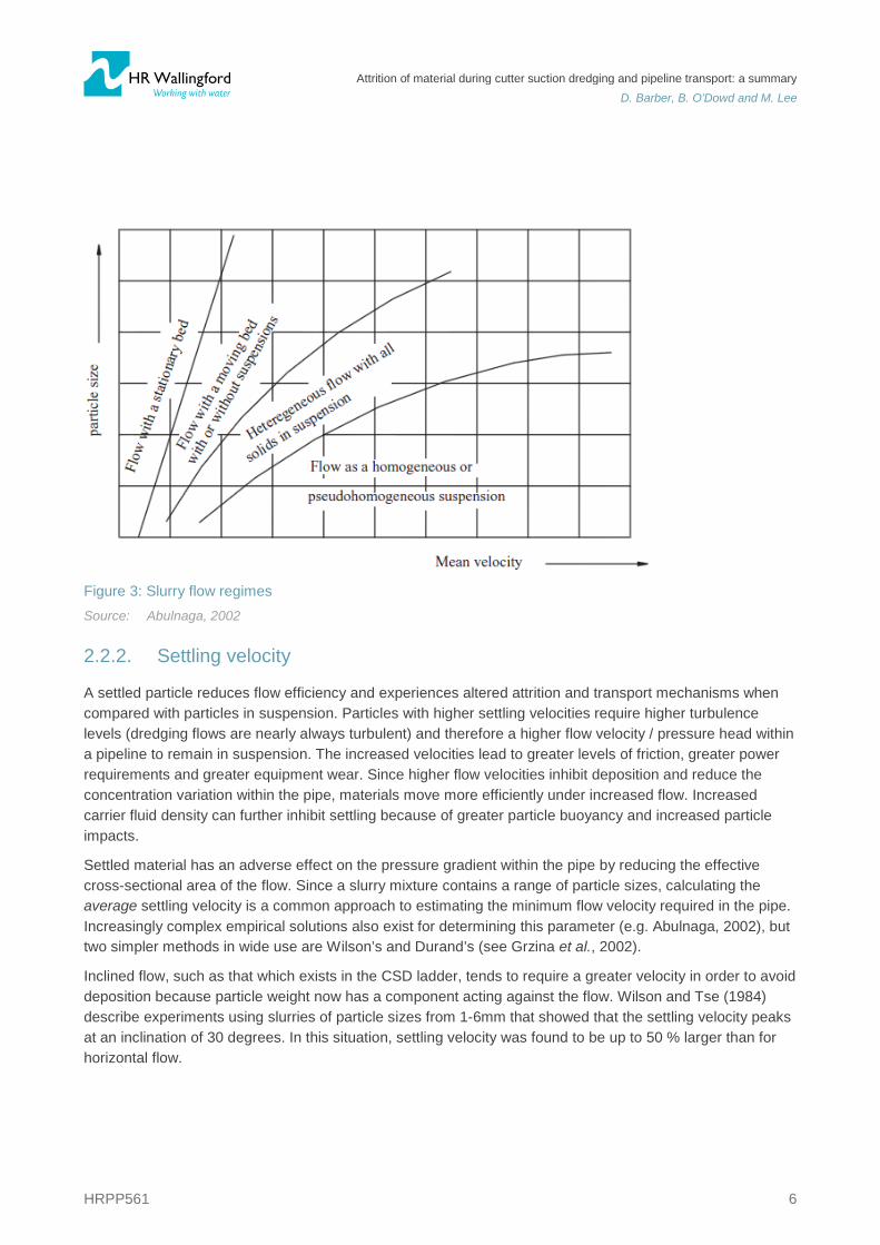
The flow regime of a slurry mixture is dependent on flow velocity, particle size and the distribution of particles over the cross-section of a pipe length (Figure 3). During hydraulic transport, slurry behaves as a carrier fluid for other dredged material because particles beneath a certain size will form a homogeneous load; Wilson (2006) suggested particles of less than 40 μm behave in this way. Such particles can be thought of as having been removed from the overall PSD to form a dense, abrasive carrier-fluid. For a slurry of this particle size fraction, the relationship between pressure head and flow velocity is that of a fluid.
Flow becomes heterogeneous when the particle size increases to medium sand. In this case, concentration is increasingly non-uniform and the mixture no longer behaves as a theoretical fluid. Following this transition, when particle size exceeds that supportable by drag and lift forces, deposition occurs. The associated regime is known as the moving bed regime.
Slip is the concept of the delivered volumetric material concentration at the pipe output being lower than the spatial volumetric material concentration within the pipe. Slip occurs because the fluid is travelling at a greater velocity than the particles supported by it, and it is primarily dictated by particle size. Greater particle sizes move at slower speeds (i.e. exhibit more slip) than finer particles do, whereas the carrying-fluid does not exhibit slip due to the fine nature of the particles within them.
Attrition of material during cutter suction dredging and pipeline transport: a summary
D. Barber, B. O’Dowd and M. Lee
HRPP561 6
Figure 3: Slurry flow regimes Source: Abulnaga, 2002
2.2.2. Settling velocity
A settled particle reduces flow efficiency and experiences altered attrition and transport mechanisms when compared with particles in suspension. Particles with higher settling velocities require higher turbulence levels (dredging flows are nearly always turbulent) and therefore a higher flow velocity / pressure head within a pipeline to remain in suspension. The increased velocities lead to greater levels of friction, greater power requirements and greater equipment wear. Since higher flow velocities inhibit deposition and reduce the concentration variation within the pipe, materials move more efficiently under increased flow. Increased carrier fluid density can further inhibit settling because of greater particle buoyancy and increased particle impacts.
Settled material has an adverse effect on the pressure gradient within the pipe by reducing the effective cross-sectional area of the flow. Since a slurry mixture contains a range of particle sizes, calculating the average settling velocity is a common approach to estimating the minimum flow velocity required in the pipe. Increasingly complex empirical solutions also exist for determining this parameter (e.g. Abulnaga, 2002), but two simpler methods in wide use are Wilson’s and Durand’s (see Grzina et al., 2002).
Inclined flow, such as that which exists in the CSD ladder, tends to require a greater velocity in order to avoid deposition because particle weight now has a component acting against the flow. Wilson and Tse (1984) describe experiments using slurries of particle sizes from 1-6mm that showed that the settling velocity peaks at an inclination of 30 degrees. In this situation, settling velocity was found to be up to 50 % larger than for horizontal flow.
Attrition of material during cutter suction dredging and pipeline transport: a summary
D. Barber, B. O’Dowd and M. Lee
HRPP561 7
2.2.3. Hydraulic gradient and the solids-effect
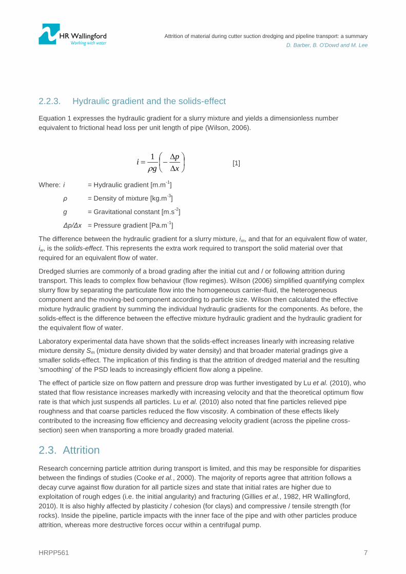
Equation 1 expresses the hydraulic gradient for a slurry mixture and yields a dimensionless number equivalent to frictional head loss per unit length of pipe (Wilson, 2006).
[1]
Where: i = Hydraulic gradient [m.m-1]
ρ = Density of mixture [kg.m-3]
g = Gravitational constant [m.s-2]
Δp/Δx = Pressure gradient [Pa.m-1]
The difference between the hydraulic gradient for a slurry mixture, im, and that for an equivalent flow of water, iw, is the solids-effect. This represents the extra work required to transport the solid material over that required for an equivalent flow of water.
Dredged slurries are commonly of a broad grading after the initial cut and / or following attrition during transport. This leads to complex flow behaviour (flow regimes). Wilson (2006) simplified quantifying complex slurry flow by separating the particulate flow into the homogeneous carrier-fluid, the heterogeneous component and the moving-bed component according to particle size. Wilson then calculated the effective mixture hydraulic gradient by summing the individual hydraulic gradients for the components. As before, the solids-effect is the difference between the effective mixture hydraulic gradient and the hydraulic gradient for the equivalent flow of water.
Laboratory experimental data have shown that the solids-effect increases linearly with increasing relative mixture density Sm (mixture density divided by water density) and that broader material gradings give a smaller solids-effect. The implication of this finding is that the attrition of dredged material and the resulting ‘smoothing’ of the PSD leads to increasingly efficient flow along a pipeline.
The effect of particle size on flow pattern and pressure drop was further investigated by Lu et al. (2010), who stated that flow resistance increases markedly with increasing velocity and that the theoretical optimum flow rate is that which just suspends all particles. Lu et al. (2010) also noted that fine particles relieved pipe roughness and that coarse particles reduced the flow viscosity. A combination of these effects likely contributed to the increasing flow efficiency and decreasing velocity gradient (across the pipeline cross-section) seen when transporting a more broadly graded material.
2.3. Attrition Research concerning particle attrition during transport is limited, and this may be responsible for disparities between the findings of studies (Cooke et al., 2000). The majority of reports agree that attrition follows a decay curve against flow duration for all particle sizes and state that initial rates are higher due to exploitation of rough edges (i.e. the initial angularity) and fracturing (Gillies et al., 1982, HR Wallingford, 2010). It is also highly affected by plasticity / cohesion (for clays) and compressive / tensile strength (for rocks). Inside the pipeline, particle impacts with the inner face of the pipe and with other particles produce attrition, whereas more destructive forces occur within a centrifugal pump.
∆∆
−=xp
gi
ρ1
Attrition of material during cutter suction dredging and pipeline transport: a summary
D. Barber, B. O’Dowd and M. Lee
HRPP561 8
Attrition during transport will increase the solids’ homogeneity and reduce the solids-effect. Many reports support this idea, showing that mixing two distinct grades of material reduced frictional losses and therefore overall energy consumption (e.g. Lu et al., 2010). Gillies et al. (1982) suggested from experimentation that attrition is actually proportional to energy consumption. Therefore, fines produced by attrition have the dual effect of increasing the cost of dewatering at the reclamation site but reducing flow friction and facilitating the flow of the larger particles.
HR Wallingford (2010) investigated attrition of rock collected from a dredging site for a range of strengths (0.8 to 23.4 MPa) in a rotary tumbling drum test (similar to those described in Section 3.2). Initially (over the shortest transport distances), the moderate strength rock (~9 MPa) showed the greatest breakup. After further tumbling, all soft and medium strength material showed near total breakup, whereas higher strength materials continued to show minimal attrition. The moderate strength rock also produced a higher percentage of fines than the weaker material.
Wilson and Addie (1997) evaluated results from pumping 10mm gravel around a pipe-loop and developed a distribution to explain pressure drop characteristics following the attrition of the solids. Over a sixty-minute period, 30 % of the coarse material mass degraded and formed a sand fraction, which caused a considerable reduction in energy loss. The sand and gravel components then interacted to reduce the solids-effect and decrease the solids-effect coefficient, which represents an exponential decay of mass lost to attrition with respect to flow duration.
2.3.1. Clay
The behaviour of clay during dredging varies widely and is primarily a function of plasticity, density and transport velocity. The plasticity index (PI) is the difference in water content at the plastic limit (PL) and that at the liquid limit (LL). At the PL, the material moves from friable to plastic behaviour until the LL is reached, at which point the water content (and therefore pore volume) between the particles is sufficient to remove cohesion, forming fluid mud.
Transportation of friable clays in a pipeline occurs as a pseudo-homogeneous mixture due to a rapid breakdown of the material. This decreases flow friction (Richter and Leshchinsky, 1994); however in reality, clays generally have a water content above the PL and therefore friable clays are rare. Highly plastic clays will remain as balls of material after cutting and will undergo transport by drag and turbulence (Matousek, 1997). These clay balls might be hundreds of millimetres in diameter and form a rolling bed, giving a lower flow efficiency than for clay that has broken down. Therefore, the intake of clays of high plasticity should be well below conventional slurry concentrations in order to maintain flow and safeguard against ball adhesion and blockages (Richter and Leshchinsky, 1994).
Leshchinsky et al. (1994) specifically tested the attrition of clay balls and considered the influences of plasticity index and stiffness. The authors used a bespoke rough drum test, like those discussed in Section 3.2. Figure 4 shows the ensuing attrition prediction curves that consider the PI, density and drum tangential velocity. The plots indicate that higher velocities and clay softnesses increase attrition and that plasticity becomes less critical with increasing density. For PIs above 54 %, there was relatively little difference in the rate of lump attrition. The plots present one specific percentage value for the rate of weight loss of a clay ball i.e. the data are independent of time. In reality, temporal variations might occur due to initial failure along existing weaknesses, or erosive effects may change as the concentration of liberated fines in the surrounding slurry increases.

Attrition of material during cutter suction dredging and pipeline transport: a summary
D. Barber, B. O’Dowd and M. Lee
HRPP561 9
Figure 4: Extract from design charts for the attrition of clay balls of varying density and plasticity Source: Richter and Leshchinsky, 1994
2.3.2. Centrifugal pumps
Centrifugal pumps are invariably the type of pump used within the dredging industry due to their ability to handle particle sizes up to 300 mm (Grzina et al., 2002). Their efficiency decreases with increasing solids concentration because the solids do not contribute to the pressure head; water flow causes a pressure increase upon meeting the pump, whereas solids continue to travel under their own momentum and expend energy through collisions and wear of the equipment. As a result, attrition during pump passage is high.
It has been suggested by major contractors within the industry that particle attrition within the pipeline length is of minor influence compared to that during pump passage, with pipeline attrition perhaps only being relevant for very long pipeline lengths. Berg and Grima (2006) compared the attrition of siliceous gravel to that of limestone and concluded that siliceous gravel degraded mainly in the pump, whereas the limestone in fact showed more attrition in the pipeline. Since the duration of travel in the pipeline is considerably longer than in the pump, a material of sufficiently high susceptibility to pipeline attrition is capable of showing higher material losses here than in the pump. Gillies et al. (1982) reported that attrition within a pump is proportional to the impellor tip speed and that breakage rates varied with impellor tangential velocity to the power of 2.5.
The lack of relevant published literature relating to attrition in centrifugal pumps suggests that manufacturers and contractors do not disseminate such information.
Attrition of material during cutter suction dredging and pipeline transport: a summary
D. Barber, B. O’Dowd and M. Lee
HRPP561 10
3. Testing methods Mobilising a CSD to site to undertake trial dredging at the planning stage of a project is an accurate way of testing and understanding the particle attrition that is likely to occur; however, such trials involve high costs and are rare as a result. At present, there is no well-established or recognised method of reproducing these processes at a laboratory scale, and the competitive nature of the industry has likely hindered progress.
This Section discusses promising approaches to laboratory testing of material attrition. The tests considered are generally either standard laboratory tests that simplify a particular physical dredging process, or scale model laboratory tests that seek to imitate a dredging process more accurately.
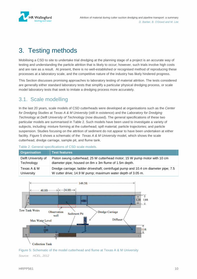
3.1. Scale modelling In the last 20 years, scale models of CSD cutterheads were developed at organisations such as the Center for Dredging Studies at Texas A & M University (still in existence) and the Laboratory for Dredging Technology at Delft University of Technology (now disused). The general specifications of these two particular models are summarised in Table 2. Such models have been used to investigate a variety of subjects, including: mixture forming at the cutterhead; spill material; particle trajectories; and particle suspension. Studies focusing on the attrition of sediment do not appear to have been undertaken at either facility. Figure 5 shows a schematic of the Texas A & M University model, which shows the scale cutterhead, dredge carriage, sample pit, and flume tank.
Table 2: General specifications of CSD scale models.
Organisation Test features
Delft University of Technology
Piston swung cutterhead; 25 W cutterhead motor; 15 W pump motor with 10 cm diameter pipe; housed on 8m x 3m flume of 1.5m depth.
Texas A & M University
Dredge carriage; ladder driveshaft; centrifugal pump and 10.4 cm diameter pipe; 7.5 W cutter drive; 14.9 W pump; maximum water depth of 3.05 m.
Figure 5: Schematic of the model cutterhead and flume at Texas A & M University Source: HCEL, 2012
Attrition of material during cutter suction dredging and pipeline transport: a summary
D. Barber, B. O’Dowd and M. Lee
HRPP561 11
The CSD model facilities are capable of reproducing variable cutting velocity, incision depth, ladder / cutterhead angle, pump capacity, suction velocity, swing speed and cutterhead power. Typical scales are 1:6 to 1:10, and material sample requirements are considerable at approximately 0.5 m3 of undisturbed material per experiment. Glover (2002) and Randall and Glover (2004) documented the design of the scale model at Texas A & M. Both authors highlighted the difficulties associated with scaling such complex processes and proposed tailoring individual experiments to the most critical scaling factors (e.g. sediment pick-up behaviour or hydraulic similarity). Glover also proposed the use of an in-situ particle size nomograph; using a single granular bed with d50 = 0.1 mm, it was suggested that sediment pick-up behaviour could be scaled by adjusting only the operational parameters of the model, such as the suction velocity. This nomograph only covered granular in-situ materials of up to d50 = 0.6 mm.
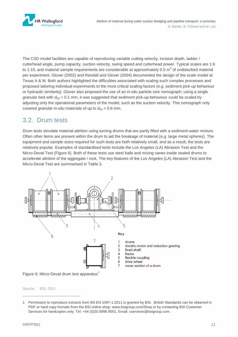
3.2. Drum tests Drum tests simulate material attrition using turning drums that are partly filled with a sediment-water mixture. Often other items are present within the drum to aid the breakage of material (e.g. large metal spheres). The equipment and sample sizes required for such tests are both relatively small, and as a result, the tests are relatively popular. Examples of standardised tests include the Los Angeles (LA) Abrasion Test and the Micro-Deval Test (Figure 6). Both of these tests use steel balls and mixing vanes inside sealed drums to accelerate attrition of the aggregate / rock. The key features of the Los Angeles (LA) Abrasion Test and the Micro-Deval Test are summarised in Table 3.
Figure 6: Micro-Deval drum test apparatus1
Source: BSI, 2011
1 Permission to reproduce extracts from BS EN 1097-1:2011 is granted by BSI. British Standards can be obtained in
PDF or hard copy formats from the BSI online shop: www.bsigroup.com/Shop or by contacting BSI Customer Services for hardcopies only: Tel: +44 (0)20 8996 9001, Email: [email protected].
Attrition of material during cutter suction dredging and pipeline transport: a summary
D. Barber, B. O’Dowd and M. Lee
HRPP561 12
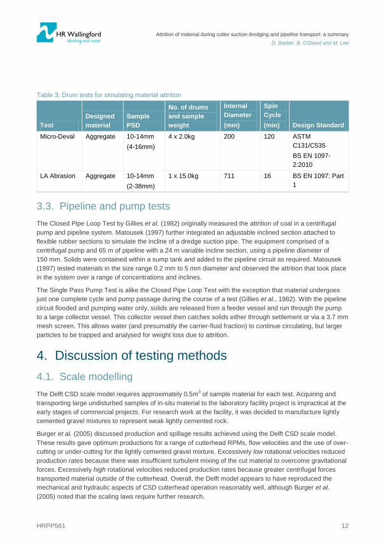
Table 3: Drum tests for simulating material attrition
Test Designed material
Sample PSD
No. of drums and sample weight
Internal Diameter (mm)
Spin Cycle (min) Design Standard
Micro-Deval Aggregate 10-14mm (4-16mm)
4 x 2.0kg 200 120 ASTM C131/C535 BS EN 1097-2:2010
LA Abrasion Aggregate 10-14mm (2-38mm)
1 x 15.0kg 711 16 BS EN 1097: Part 1
3.3. Pipeline and pump tests The Closed Pipe Loop Test by Gillies et al. (1982) originally measured the attrition of coal in a centrifugal pump and pipeline system. Matousek (1997) further integrated an adjustable inclined section attached to flexible rubber sections to simulate the incline of a dredge suction pipe. The equipment comprised of a centrifugal pump and 65 m of pipeline with a 24 m variable incline section, using a pipeline diameter of 150 mm. Solids were contained within a sump tank and added to the pipeline circuit as required. Matousek (1997) tested materials in the size range 0.2 mm to 5 mm diameter and observed the attrition that took place in the system over a range of concentrations and inclines.
The Single Pass Pump Test is alike the Closed Pipe Loop Test with the exception that material undergoes just one complete cycle and pump passage during the course of a test (Gillies et al., 1982). With the pipeline circuit flooded and pumping water only, solids are released from a feeder vessel and run through the pump to a large collector vessel. This collector vessel then catches solids either through settlement or via a 3.7 mm mesh screen. This allows water (and presumably the carrier-fluid fraction) to continue circulating, but larger particles to be trapped and analysed for weight loss due to attrition.
4. Discussion of testing methods 4.1. Scale modelling The Delft CSD scale model requires approximately 0.5m3 of sample material for each test. Acquiring and transporting large undisturbed samples of in-situ material to the laboratory facility project is impractical at the early stages of commercial projects. For research work at the facility, it was decided to manufacture lightly cemented gravel mixtures to represent weak lightly cemented rock.
Burger et al. (2005) discussed production and spillage results achieved using the Delft CSD scale model. These results gave optimum productions for a range of cutterhead RPMs, flow velocities and the use of over-cutting or under-cutting for the lightly cemented gravel mixture. Excessively low rotational velocities reduced production rates because there was insufficient turbulent mixing of the cut material to overcome gravitational forces. Excessively high rotational velocities reduced production rates because greater centrifugal forces transported material outside of the cutterhead. Overall, the Delft model appears to have reproduced the mechanical and hydraulic aspects of CSD cutterhead operation reasonably well, although Burger et al. (2005) noted that the scaling laws require further research.
Attrition of material during cutter suction dredging and pipeline transport: a summary
D. Barber, B. O’Dowd and M. Lee
HRPP561 13
Glover (2002) discussed the scaling methodology applied to the facility at Texas A & M and the inherent difficulties associated with achieving both hydraulic and mechanical similarity. For non-cohesive granular material, sediment pick-up behaviour and cutting forces were considered to be readily scalable in this facility. Accurate representation of these processes is essential if a cut PSD entering the suction pipe is to be replicated. The cost of the Texas A & M model was estimated by Glover (2002) to be $160,000 (excluding the flume that was already in place), meaning scale modelling would be beyond the means of many organisations.
4.2. Drum tests The standardised drum tests allow a quantitative comparison of attrition rates for all non-cohesive materials. The Micro-Deval and LA Abrasion Tests have been in use for decades within the aggregate industry and quantities of data already exist. These tests are also easy and affordable enough (see Table 4) for large databases of results to be built. Such databases are of little value for dredging projects, however, if the tests themselves do not represent / relate to the physical processes that occur during dredging. In many instances, this would appear to be the case.
Table 4: Drum laboratory tests: equipment cost and size(March 2012)
Test apparatus Cost (exc. tax) W x D x H (m)
Weight (kg) Source
Micro-Deval 4,600 USD 0.52 x 0.34 x 0.97 75 www.globalgilson.com
LA Abrasion 10,000 USD 0.97 x 1.02 x 1.18 544 www.globalgilson.com
There appeared to have been little investigation of the nature of particle flow or segregation within a rotating drum. Without segregation, there can be limited representation of the flow regimes that exist during hydraulic transport.
The steel balls and mixing vanes in the closed drum tests increase turbulences and attrition / breakage; this would appear inappropriate for soft rocks or plastic clays that might rapidly break-up in an unrepresentative way.
The Micro-Deval and LA Abrasion Tests have strict PSD requirements (see Table 3) that may not match CSD dredged PSDs. For example, the British Standard (BSI, 2011) for the Micro Deval Test specifies the mass of the sample sent to the laboratory shall have at least 2 kg of particles of size 10 to 14 mm. In addition, the grading of the test portion should comply with at least one of the following requirements:
30 to 40 % passing a 11.2 mm sieve; or
60 to 70 % passing a 12.5 mm sieve.
Different end uses are described in the appendix to the British Standard, but it is noted that testing other size fractions may produce different results to those obtained using the conventional 10/14 mm size fraction. A modified approach may be beneficial for the analysis of materials associated with dredging projects.
4.3. Pipeline and pump tests In a pipe loop system, real pipe flow conditions occur and it is possible to calibrate the flow to match that found within a dredge pipeline. This allows such facilities to reproduce flow regimes, turbulence levels and velocity profiles, which are all critical to the levels of particle suspension and distribution in the flow cross-
Attrition of material during cutter suction dredging and pipeline transport: a summary
D. Barber, B. O’Dowd and M. Lee
HRPP561 14
section. However, no references were found in the literature to the scaling of flow variables and particle size to represent those of pipelines in full-scale dredgers.
There are several drawbacks to using a closed pipe system: repeated pump passages greatly distort attrition; sample requirements might be up to 500 kg (estimated for Matousek’s (1997) set-up); and, as with all pipeline experiments, there is a delay before the flow fully mixes and stabilises.
The single-pass pump eliminates the need for initial mixing because the focus is only on attrition within the pump, not flow representation. Even so, the results from single-pass attrition studies may be misleading as initial attrition rates are high due to existing fractures and angularity. It may be possible to address this issue, to some extent, by pre-circulating the mixture. The catching mesh in the Single Pass Pump Test was 3.7mm (small enough to catch clay balls and gravels), but smaller meshes would be desirable to avoid recirculation of the finer fractions during unloading of the entire material sample.
Costs for centrifugal pumps and pipelines can be estimated from the CIRIA Cost Standards (Bray, 2009) and market prices. A system like Matousek’s (Section 3.3) might initially cost in excess of $100,000 (before considering sample collection and running costs), which is one order of magnitude greater than the cost of drum tests.
5. Conclusions Dredging of rock or sediment using a cutter suction dredger (CSD) often results in significant changes to
the character of the material. Such changes can be of great importance when considering re-use of the material; for example, in a reclamation area.
In rock and clay, the excavation of material occurs via ductile or brittle failure mechanisms. The latter gives greater chip sizes and generally better production rates. The character of natural discontinuities / weaknesses in rocks is critical when considering the material’s break-up by either ripping or cutting forces.
Solids’ flow behaviour during pipeline transport is heavily dependent on the particle size distribution of the excavated material.
For weak materials, the overall amount of attrition undergone appears to be greater in long pipelines than in pumps. The reverse appears true for stronger materials due to destructive forces in pumps being greater.
During hydraulic transport, the flow efficiency and pressure gradient improves with a broader PSD grading because the mixture becomes more homogeneous and dense, which facilitates particle support.
Attrition of material generally follows a decay behaviour (by mass lost). Attrition and the resulting broadening of the PSD distribution reduces the solids-effect (the work required to transport the sediment).
Scale models of CSDs have produced promising results in simulating excavation (cutterhead) processes within the laboratory environment, though they suffer from scaling issues, high initial costs, and large sample size requirements.
Drum test simulation of pipeline attrition offers small-scale, low cost testing of the behaviour of hard clays and all rock strengths. However, the representation of the full-scale processes appears to be poor and little information is available regarding calibrating or scaling such laboratory results. Results may thus be largely qualitative (or at best semi-quantitative) in their relation to dredging.
Attrition of material during cutter suction dredging and pipeline transport: a summary
D. Barber, B. O’Dowd and M. Lee
HRPP561 15
Pipeline and pump tests are the most reliable method of reproducing pipeline and pump processes and attrition. Such tests allow modelling of sub-gravel sized particle attrition. The cost of these test facilities approaches that of scale models.
6. References Abulnaga B.E. (2002). Slurry Systems Handbook. McGraw-Hill.
Berg C.H. van den and A.M. Grima (2006). Effects of Degradation on Slurry Performance. 13th Conference on Transport and Sedimentation of Solid Particles, Tbilissi, eds Gochitashvili and Sobota, 39-47.
Bray R.N., A.D. Bates and J.M. Land (1997). Dredging; A Handbook For Engineers 2nd Edition. Arnold, Oxford, England.
Bray R.N. (2009). A Guide to Cost Standards for Dredging Equipment, CIRIA C684. CIRIA.
BSI (2011). Tests for Mechanical and Physical Properties of Aggregates Part 1: Determination of the Resistance to Wear (Micro-Deval). BSI Standards Publication BS EN 1097-1:2011.
Burger M., W.J. Vlasblom and A.M. Talmon (2005). Design Aspects for Cutter Heads Related to the Mixture Forming Process When Cutting Coarse Materials. Terra et Aqua – Number 98, March 2005, pp. 12-18.
Cooke R., G. Johnson and P. Goosen (2000). Laboratory Apparatus for Evaluating Slurry Pipeline Wear. SAIT Seminar - Economics of Wear Materials.
Geking K. (1987). Rock Testing Procedures at VA’s Geotechnical Laboratory in Zeltweg, International Report TZU 48. Voest Alphine Zeltweg, Austria.
Gillies R.G., D.B. Haas, W.H.W. Husband, M. Small and C.A. Shook (1982). A System to Determine Single-Pass Particle Degradation by Pumps. Proc. Hydrotransport 8, BHRA Fluid Engineering, Cranfield, UK, pp. 415-431.
Glover G.J. (2002). Laboratory Modelling of Hydraulic Dredges and Design of Dredge Carriage for Laboratory Facility. MSc Thesis, Texas A&M University.
Grzina A., A. Roudnev and K.E. Burgess (2002). Slurry Pumping Manual: A Technical Application Guide for Users of Centrifugal Pumps and Slurry Pumping Systems, 1st Ed. Warman International Ltd of Weir Group plc.
HCEL (2012). Haynes Coastal Engineering Laboratory “Industry & Researchers”. http://coastal.tamu.edu/forindustry.html. Accessed 25th October 2012.
HR Wallingford (2010). Laboratory Disaggregation and Abrasion Testing of Selected Sediment Samples, (Commercial in confidence).
Leshchinsky D., S.D. Richter, J. Fowler and P. Gilbert (1994). Dredging Research; Technical Notes; Degradation of Hydraulically Transported Clay Balls. DRP-2-09, August 1994. USACE.
Lu H., J. Yin, Y. Yuan and J. Wang (2010). Effect of Particle Size Distribution on Flow Pattern and Pressure Drop in Pipeline Flow of Slurries. 2nd Conference on Environmental Science and Information Applied Technology, IEEE, pp. 40-42.
Matousek V. (1997). Flow Mechanism of Sand-Water Mixtures in Pipelines. Delft University Press.
Attrition of material during cutter suction dredging and pipeline transport: a summary
D. Barber, B. O’Dowd and M. Lee
HRPP561 16
Miedema S.A. (2009). New Developments of Cutting Theories with Respect to Dredging; The Cutting of Clay and Rock. WEDA XXIX & Texas A&M 40. Phoenix Arizona, USA, June 14-17 2009.
Miedema S.A. (2010). New Developments of Cutting Theories with Respect to Offshore Applications; The Cutting of Sand, Clay and Rock. ISOPE 2010, Beijing China, June 2010.
Randall R.E. and G.J. Glover (2004). Scaling of Model Hydraulic Dredges with Application to Design of a Dredge Modelling Facility. Journal of Dredging Engineering, WEDA, Vol. 6, No 2, September 2004.
Richter S.D. and D. Leshchinsky (1994). Hydraulically Transported Clay Balls - Contract Report DRP-94-1 April 1994. USACE.
Schrieck, G.L.M. van der (2009). Dredging Technology, Course notes CIE5300, GLM van der Schrieck BV, Burg. Den Texclaan 43, NL 2111 CC, Aerdenhout, Holland, [email protected].
Verhoef P.N.W. (1997). Wear of Rock Cutting Tools; Implications for the Site Investigation of Rock Dredging Projects. CRC Press.
Vlasblom W.J. (2005). Chapter 3: Cutter Suction Dredger, CEDA Lecture notes, Wb3408b, May 2005.
Wilson K.C. (2006). Slurry Transport Using Centrifugal Pumps, 3ed. Springer.
Wilson K.C. and G.R. Addie (1997). Coarse-Particle Pipeline Transport: Effect of Particle Degradation on Friction. Power Technology 94, pp. 235-238.
Wilson K.C. and J.K.P. Tse (1984). Deposition Limit for Coarse-Particle Transport in Inclines Pipes. Proc. Hydrotransport 9, BHRA Fluid Engineering, pp. 149-169.