august 07 ncma hardscape rev.:cm aug hardscape 07
TRANSCRIPT
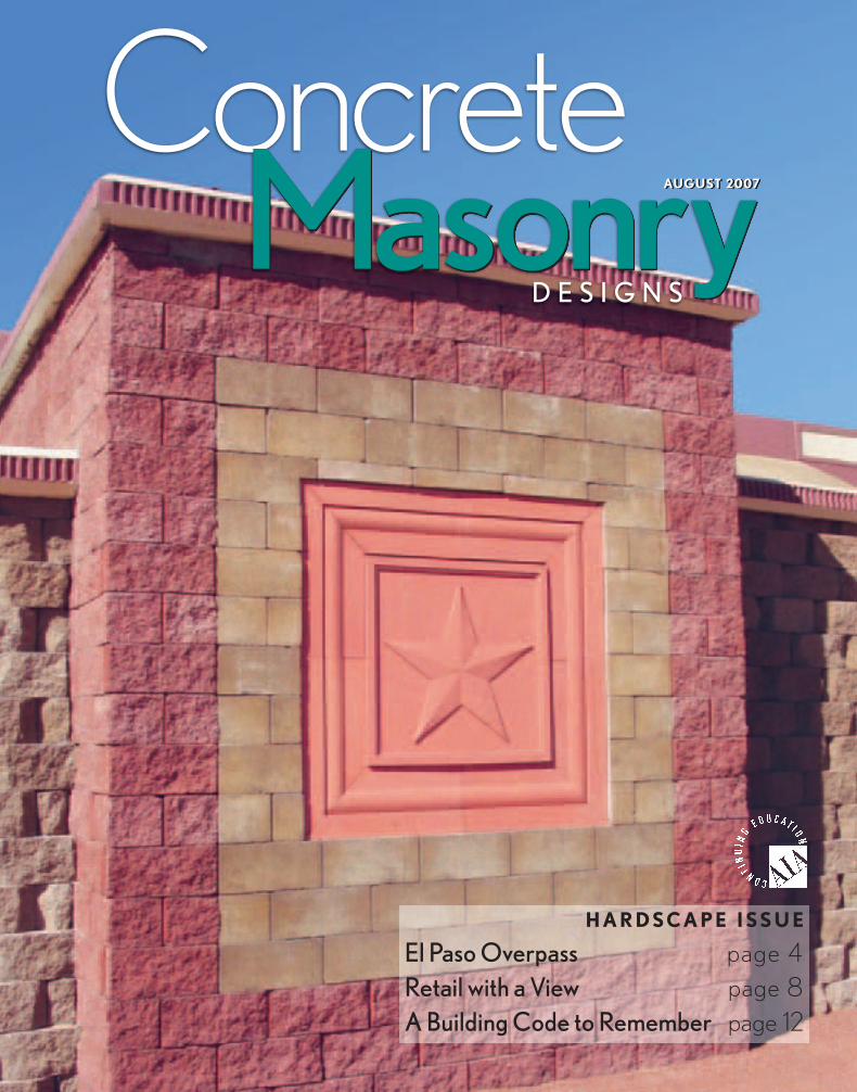
AUGUST 2007MasonryConcrete
MasonryD E S I G N S
AUGUST 2007
H A R D SC A P E I SS U E
El Paso Overpass page 4Retail with a View page 8A Building Code to Remember page 12
August 07 NCMA Hardscape Rev.:CM AUG HARDSCAPE 07 8/3/07 4:57 PM Page C1
August 07 NCMA Hardscape Rev.:CM AUG HARDSCAPE 07 8/3/07 3:59 PM Page 2

Concrete Masonry Designs I Hardscape Issue ■ 3
Publisher:Mark B. Hogan, P.E., NCMA President
Editor:Michele R. Bupp, [email protected]
Associate Editors: Dennis W. Graber, P.E., Harry W. Junk,Rodger R. Prunty II, P.E., Robert D.Thomas, Michael F. Werner, P.E.
Advertising: Ron Churchill, [email protected]
Concrete Masonry Designs magazine show-cases the qualities and aesthetics of designand construction using concrete masonry.
Concrete Masonry Designs is devoted to design techniques using standard andarchitectural concrete masonry units, concretebrick, unit concrete pavers, segmental retain-ing walls, and other concrete masonry prod-ucts around the world. We welcome your editorial comments, ideas, and submissions.
Copyright 2007 by the National ConcreteMasonry Association. All rights reserved.Contents may not be reprinted or reproduced without written permission from NCMA.
Concrete Masonry Designs is published monthly by the National Concrete MasonryAssociation (NCMA), and distributed toadvance and support the concrete masonryindustry and public interest.
Send address corrections and subscription inquiries to: NCMA Sales and Marketing Department13750 Sunrise Valley DriveHerndon, VA 20171-4662703-713-1900 Fax 703-713-1910www.ncma.org
MasonryMasonryD E P A R T M E N T S
11 Technical Resources
14 AIA Continuing Education Reporting Form
15 Detail of the Month
P R O J E C T C R E D I T S
“El Paso Overpass”: Dan Williams Company
and Texas Department of Transportation,
El Paso, Tex.; Scott Miller Consulting
Engineer, North Little Rock, Ark.
“Retail with a View”: All Season Land-
scaping, Eleva, Wis., Ayres Associates,
Oakwood Business Park LLC, and Shoppes
at Oakwood, Eau Claire, Wis.; Mattsen
Construction, Knapp, Wis.
H a r d s c a p e I s s u e I August 2007
F E A T U R E S
4El Paso Overpass In a booming Texas city, concrete masonrysegmental retaining walls add color to a highway surrounded by scrub desert.
8Retail with a View Because production of concrete masonryunits is so flexible, the designers of thisupscale shopping center in Wisconsin could choose colors and textures that complemented the surroundings.
12A Building Code to RememberCurrent codes are in place to determinewhen the height of an SRW warrants a railing at the top.
O N T H E C O V E R :
The Loop 375 overpass in El Paso, Texas, is constructed
of concrete masonry segmental retaining walls. Here is one
of five planters protruding from the walls, which displays
a star symbolizing the Lone Star state. The other planters
have a gecko and sun.
August 07 NCMA Hardscape Rev.:CM AUG HARDSCAPE 07 8/3/07 3:59 PM Page 3
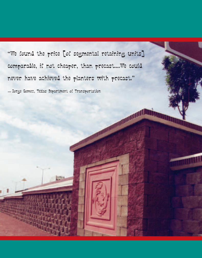
“We found the price [of segmental retaining units]
comparable, if not cheaper, than precast….We could
never have achieved the planters with precast.”
— Jorge Gomez, Texas Department of Transportation
August 07 NCMA Hardscape Rev.:CM AUG HARDSCAPE 07 8/3/07 3:59 PM Page 4
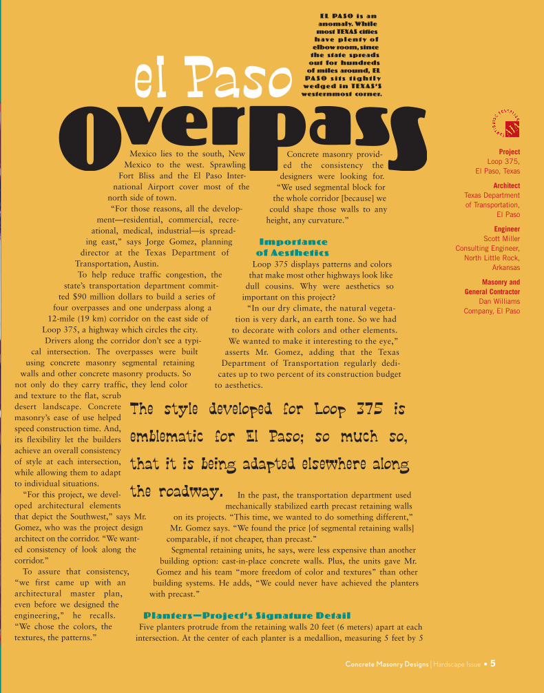
Mexico lies to the south, NewMexico to the west. Sprawling
Fort Bliss and the El Paso Inter-national Airport cover most of the
north side of town.“For those reasons, all the develop-
ment—residential, commercial, recre-ational, medical, industrial—is spread-
ing east,” says Jorge Gomez, planningdirector at the Texas Department of
Transportation, Austin.To help reduce traffic congestion, the
state’s transportation department commit-ted $90 million dollars to build a series of
four overpasses and one underpass along a12-mile (19 km) corridor on the east side of
Loop 375, a highway which circles the city. Drivers along the corridor don’t see a typi-
cal intersection. The overpasses were builtusing concrete masonry segmental retaining
walls and other concrete masonry products. Sonot only do they carry traffic, they lend colorand texture to the flat, scrubdesert landscape. Concretemasonry’s ease of use helpedspeed construction time. And,its flexibility let the buildersachieve an overall consistencyof style at each intersection,while allowing them to adaptto individual situations.
“For this project, we devel-oped architectural elementsthat depict the Southwest,” says Mr.Gomez, who was the project designarchitect on the corridor. “We want-ed consistency of look along thecorridor.”
To assure that consistency,“we first came up with anarchitectural master plan,even before we designed theengineering,” he recalls.“We chose the colors, thetextures, the patterns.”
Concrete Masonry Designs I Hardscape Issue ■ 5
ProjectLoop 375,
El Paso, Texas
ArchitectTexas Department of Transportation,
El Paso
EngineerScott Miller
Consulting Engineer, North Little Rock,
Arkansas
Masonry and General Contractor
Dan Williams Company, El Paso
Concrete masonry provid-ed the consistency the
designers were looking for.“We used segmental block for
the whole corridor [because] wecould shape those walls to any
height, any curvature.”
Importance of Aesthetics
Loop 375 displays patterns and colorsthat make most other highways look like
dull cousins. Why were aesthetics soimportant on this project?
“In our dry climate, the natural vegeta-tion is very dark, an earth tone. So we had
to decorate with colors and other elements.We wanted to make it interesting to the eye,”
asserts Mr. Gomez, adding that the TexasDepartment of Transportation regularly dedi-
cates up to two percent of its construction budgetto aesthetics.
In the past, the transportation department usedmechanically stabilized earth precast retaining walls
on its projects. “This time, we wanted to do something different,”Mr. Gomez says. “We found the price [of segmental retaining walls]
comparable, if not cheaper, than precast.”Segmental retaining units, he says, were less expensive than another
building option: cast-in-place concrete walls. Plus, the units gave Mr.Gomez and his team “more freedom of color and textures” than other
building systems. He adds, “We could never have achieved the planterswith precast.”
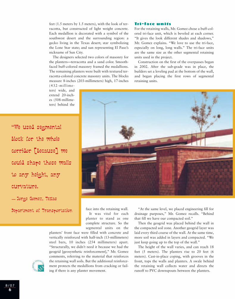
Planters—Project’s Signature DetailFive planters protrude from the retaining walls 20 feet (6 meters) apart at each
intersection. At the center of each planter is a medallion, measuring 5 feet by 5
E L PA S O i s a nanomaly. While
most TEXAS citiesh ave p l e n t y o f
elbow room, sincethe state spreads
out for hundredsof miles around, EL
PA S O s i t s t i g h t l ywe d g e d i n T E X A S ’ S
westernmost corner.el Paso
The style developed for Loop 375 is
emblematic for El Paso; so much so,
that it is being adapted elsewhere along
the roadway.
August 07 NCMA Hardscape Rev.:CM AUG HARDSCAPE 07 8/3/07 4:00 PM Page 5
8 / 0 76
feet (1.5 meters by 1.5 meters), with the look of ter-racotta, but constructed of light weight concrete.Each medallion is decorated with a symbol of thesouthwest desert and the surrounding region: agecko living in the Texas desert; star symbolizingthe Lone Star state; and sun representing El Paso’snickname of Sun City.
The designers selected two colors of masonry forthe planters—terracotta and a sand color. Smooth-faced buff-colored masonry framed the medallions.The remaining planters were built with textured ter-racotta-colored concrete masonry units. The blocksmeasure 8-inches (203-millimeters) high, 17-inches(432-mil l ime-ters) wide, andextend 20-inch-es (508-millime-ters) behind the
face into the retaining wall.It was vital for each
planter to stand as onecomplete structure. So thesegmental units on the
planters’ front face were filled with concrete andvertically reinforced with half-inch (13-millimeters)steel bars, 10 inches (254 millimeters) apart.“Structurally, we didn’t need it because we had thegeogrid [geosynthetic reinforcement],” Mr. Gomezcomments, referring to the material that reinforcesthe retaining wall soils. But the additional reinforce-ment protects the medallions from cracking or fail-ing if there is any planter movement.
Tr i - f a ce u n i t sFor the retaining walls, Mr. Gomez chose a buff-col-ored tri-face unit, which is beveled at each corner.“It gives the look different shades and shadows,”Mr. Gomez explains. “We love to use the tri-face,especially on long, long walls.” The tri-face unitsare the same size as the other segmental retainingunits used in the project.
Construction on the first of the overpasses beganin 2002. After the sub-grade was in place, thebuilders set a leveling pad at the bottom of the wall,and began placing the first rows of segmentalretaining units.
“At the same level, we placed engineering fill fordrainage purposes,” Mr. Gomez recalls. “Behindthat fill we have our compacted soil.”
Then the geogrid was placed behind the wall inthe compacted soil zone. Another geogrid layer waslaid every third course of the wall. At the same time,more soil was added in layers and compacted. “Wejust keep going up to the top of the wall.”
The height of the wall varies, and can reach 18feet (5 meters). The planters rise to 20 feet (6meters). Cast-in-place coping, with grooves in thefront, tops the walls and planters. A swale behindthe retaining wall collects water and directs therunoff to PVC downspouts between the planters.
“We used segmental
block for the whole
corridor [because] we
could shape those walls
to any height, any
curvature.
— Jorge Gomez, Texas
Department of Transportation
August 07 NCMA Hardscape Rev.:CM AUG HARDSCAPE 07 8/3/07 4:00 PM Page 6
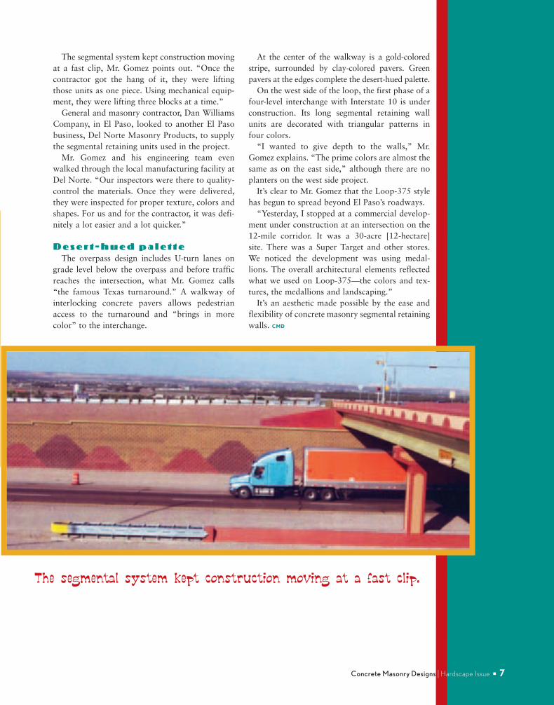
The segmental system kept construction movingat a fast clip, Mr. Gomez points out. “Once thecontractor got the hang of it, they were liftingthose units as one piece. Using mechanical equip-ment, they were lifting three blocks at a time.”
General and masonry contractor, Dan WilliamsCompany, in El Paso, looked to another El Pasobusiness, Del Norte Masonry Products, to supplythe segmental retaining units used in the project.
Mr. Gomez and his engineering team evenwalked through the local manufacturing facility atDel Norte. “Our inspectors were there to quality-control the materials. Once they were delivered,they were inspected for proper texture, colors andshapes. For us and for the contractor, it was defi-nitely a lot easier and a lot quicker.”
D e s e r t - h u e d p a l e t t eThe overpass design includes U-turn lanes on
grade level below the overpass and before trafficreaches the intersection, what Mr. Gomez calls“the famous Texas turnaround.” A walkway ofinterlocking concrete pavers allows pedestrianaccess to the turnaround and “brings in morecolor” to the interchange.
At the center of the walkway is a gold-coloredstripe, surrounded by clay-colored pavers. Greenpavers at the edges complete the desert-hued palette.
On the west side of the loop, the first phase of afour-level interchange with Interstate 10 is underconstruction. Its long segmental retaining wallunits are decorated with triangular patterns infour colors.
“I wanted to give depth to the walls,” Mr.Gomez explains. “The prime colors are almost thesame as on the east side,” although there are noplanters on the west side project.
It’s clear to Mr. Gomez that the Loop-375 stylehas begun to spread beyond El Paso’s roadways.
“Yesterday, I stopped at a commercial develop-ment under construction at an intersection on the12-mile corridor. It was a 30-acre [12-hectare]site. There was a Super Target and other stores.We noticed the development was using medal-lions. The overall architectural elements reflectedwhat we used on Loop-375—the colors and tex-tures, the medallions and landscaping.”
It’s an aesthetic made possible by the ease andflexibility of concrete masonry segmental retainingwalls. CMD
Concrete Masonry Designs I Hardscape Issue ■ 7
The segmental system kept construction moving at a fast clip.
August 07 NCMA Hardscape Rev.:CM AUG HARDSCAPE 07 8/3/07 4:00 PM Page 7
8 / 0 78
TERRACING HAS BEEN USED FOR THOUSANDS
OF YEARS TO TURN SHEER HILLSIDES INTO PRO-
DUCTIVE AGRICULTURAL LAND. IN EAU CLAIRE,
WISCONSIN, THEY ADAPTED THE CONCEPT TO
MAKE A STEEP SLOPE FIT FOR RETAIL SHOPPING.
When developers of the Shoppes at Oakwoodsearched for a site near a new mall in a growing com-mercial section of the western Wisconsin city, theyfound no flat land available. They settled on 7.3 acre(3 hectare) site with a significant slope along thestreet side of the property. And from the street, asteep hill rose toward the back of the site.
“From front to back, the grade increases 50 feet[15 meters],” says Disa Wahlstrand, P.E., manager ofmunicipal services for Ayres Associates, a nationalarchitectural and engineering consulting firm provid-ing services for the Shoppes of Oakwood project.“That city street climbs up a hill, a 60-80-foot [18-24-meter] incline—an 8-10-degree slope.”
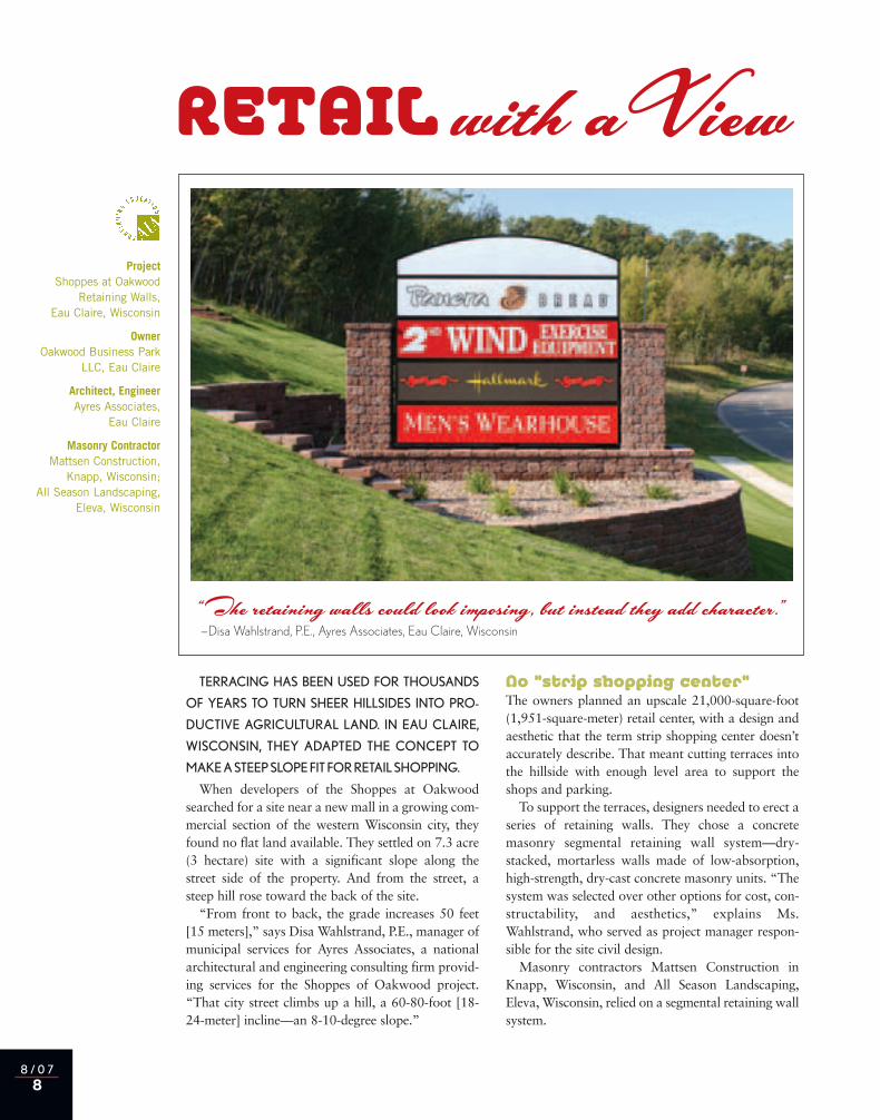
No “strip shopping center”The owners planned an upscale 21,000-square-foot(1,951-square-meter) retail center, with a design andaesthetic that the term strip shopping center doesn’taccurately describe. That meant cutting terraces intothe hillside with enough level area to support theshops and parking.
To support the terraces, designers needed to erect aseries of retaining walls. They chose a concretemasonry segmental retaining wall system—dry-stacked, mortarless walls made of low-absorption,high-strength, dry-cast concrete masonry units. “Thesystem was selected over other options for cost, con-structability, and aesthetics,” explains Ms.Wahlstrand, who served as project manager respon-sible for the site civil design.
Masonry contractors Mattsen Construction inKnapp, Wisconsin, and All Season Landscaping,Eleva, Wisconsin, relied on a segmental retaining wallsystem.
ProjectShoppes at Oakwood
Retaining Walls,Eau Claire, Wisconsin
OwnerOakwood Business Park
LLC, Eau Claire
Architect, EngineerAyres Associates,
Eau Claire
Masonry ContractorMattsen Construction,
Knapp, Wisconsin; All Season Landscaping,
Eleva, Wisconsin
RETAIL with aView
“The retaining walls could look imposing, but instead they add character.”—Disa Wahlstrand, P.E., Ayres Associates, Eau Claire, Wisconsin
August 07 NCMA Hardscape Rev.:CM AUG HARDSCAPE 07 8/3/07 4:00 PM Page 8
Concrete Masonry Designs I Hardscape Issue ■ 9
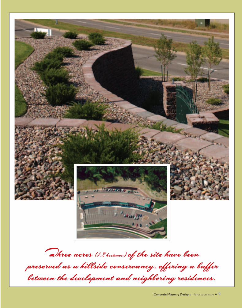
Three acres (1.2 hectares) of the site have been
preserved as a hillside conservancy, offering a buffer
between the development and neighboring residences.
August 07 NCMA Hardscape Rev.:CM AUG HARDSCAPE 07 8/3/07 4:00 PM Page 9
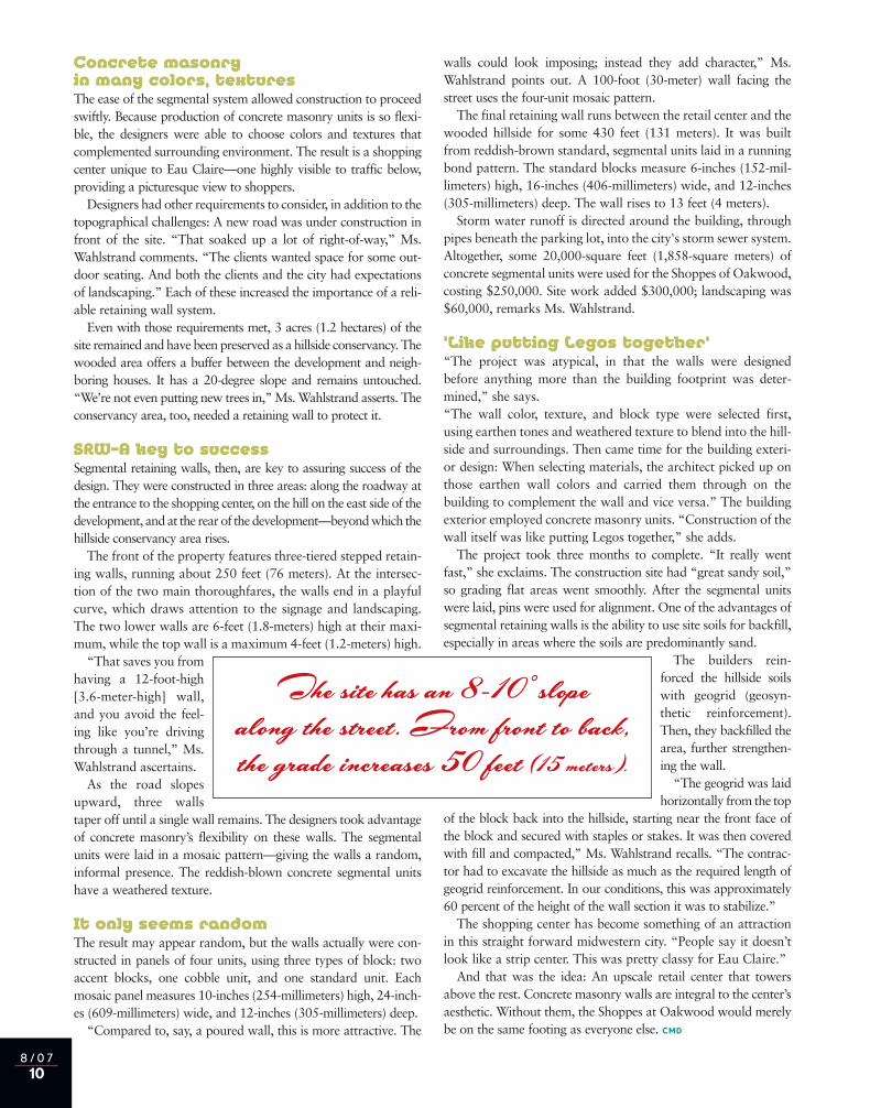
Concrete masonry in many colors, texturesThe ease of the segmental system allowed construction to proceedswiftly. Because production of concrete masonry units is so flexi-ble, the designers were able to choose colors and textures thatcomplemented surrounding environment. The result is a shoppingcenter unique to Eau Claire—one highly visible to traffic below,providing a picturesque view to shoppers.
Designers had other requirements to consider, in addition to thetopographical challenges: A new road was under construction infront of the site. “That soaked up a lot of right-of-way,” Ms.Wahlstrand comments. “The clients wanted space for some out-door seating. And both the clients and the city had expectationsof landscaping.” Each of these increased the importance of a reli-able retaining wall system.
Even with those requirements met, 3 acres (1.2 hectares) of thesite remained and have been preserved as a hillside conservancy. Thewooded area offers a buffer between the development and neigh-boring houses. It has a 20-degree slope and remains untouched.“We’re not even putting new trees in,” Ms. Wahlstrand asserts. Theconservancy area, too, needed a retaining wall to protect it.
SRW—A key to successSegmental retaining walls, then, are key to assuring success of thedesign. They were constructed in three areas: along the roadway atthe entrance to the shopping center, on the hill on the east side of thedevelopment, and at the rear of the development—beyond which thehillside conservancy area rises.
The front of the property features three-tiered stepped retain-ing walls, running about 250 feet (76 meters). At the intersec-tion of the two main thoroughfares, the walls end in a playfulcurve, which draws attention to the signage and landscaping.The two lower walls are 6-feet (1.8-meters) high at their maxi-mum, while the top wall is a maximum 4-feet (1.2-meters) high.
“That saves you fromhaving a 12-foot-high[3.6-meter-high] wall,and you avoid the feel-ing like you’re drivingthrough a tunnel,” Ms.Wahlstrand ascertains.
As the road slopesupward, three wallstaper off until a single wall remains. The designers took advantageof concrete masonry’s flexibility on these walls. The segmentalunits were laid in a mosaic pattern—giving the walls a random,informal presence. The reddish-blown concrete segmental unitshave a weathered texture.
It only seems randomThe result may appear random, but the walls actually were con-structed in panels of four units, using three types of block: twoaccent blocks, one cobble unit, and one standard unit. Eachmosaic panel measures 10-inches (254-millimeters) high, 24-inch-es (609-millimeters) wide, and 12-inches (305-millimeters) deep.
“Compared to, say, a poured wall, this is more attractive. The
walls could look imposing; instead they add character,” Ms.Wahlstrand points out. A 100-foot (30-meter) wall facing thestreet uses the four-unit mosaic pattern.
The final retaining wall runs between the retail center and thewooded hillside for some 430 feet (131 meters). It was builtfrom reddish-brown standard, segmental units laid in a runningbond pattern. The standard blocks measure 6-inches (152-mil-limeters) high, 16-inches (406-millimeters) wide, and 12-inches(305-millimeters) deep. The wall rises to 13 feet (4 meters).
Storm water runoff is directed around the building, throughpipes beneath the parking lot, into the city's storm sewer system.Altogether, some 20,000-square feet (1,858-square meters) ofconcrete segmental units were used for the Shoppes of Oakwood,costing $250,000. Site work added $300,000; landscaping was$60,000, remarks Ms. Wahlstrand.
‘Like putting Legos together’“The project was atypical, in that the walls were designedbefore anything more than the building footprint was deter-mined,” she says.“The wall color, texture, and block type were selected first,using earthen tones and weathered texture to blend into the hill-side and surroundings. Then came time for the building exteri-or design: When selecting materials, the architect picked up onthose earthen wall colors and carried them through on thebuilding to complement the wall and vice versa.” The buildingexterior employed concrete masonry units. “Construction of thewall itself was like putting Legos together,” she adds.
The project took three months to complete. “It really wentfast,” she exclaims. The construction site had “great sandy soil,”so grading flat areas went smoothly. After the segmental unitswere laid, pins were used for alignment. One of the advantages ofsegmental retaining walls is the ability to use site soils for backfill,especially in areas where the soils are predominantly sand.
The builders rein-forced the hillside soilswith geogrid (geosyn-thetic reinforcement).Then, they backfilled thearea, further strengthen-ing the wall.
“The geogrid was laidhorizontally from the top
of the block back into the hillside, starting near the front face ofthe block and secured with staples or stakes. It was then coveredwith fill and compacted,” Ms. Wahlstrand recalls. “The contrac-tor had to excavate the hillside as much as the required length ofgeogrid reinforcement. In our conditions, this was approximately60 percent of the height of the wall section it was to stabilize.”
The shopping center has become something of an attractionin this straight forward midwestern city. “People say it doesn’tlook like a strip center. This was pretty classy for Eau Claire.”
And that was the idea: An upscale retail center that towersabove the rest. Concrete masonry walls are integral to the center’saesthetic. Without them, the Shoppes at Oakwood would merelybe on the same footing as everyone else. CMD
8 / 0 710
The site has an 8-10 ˚slope
along the street. From front to back,
the grade increases 50 feet (15 meters).
August 07 NCMA Hardscape Rev.:CM AUG HARDSCAPE 07 8/3/07 4:00 PM Page 10
Concrete Masonry Designs I Hardscape Issue ■ 11
T E C H N I C A L R E S O U R C E S
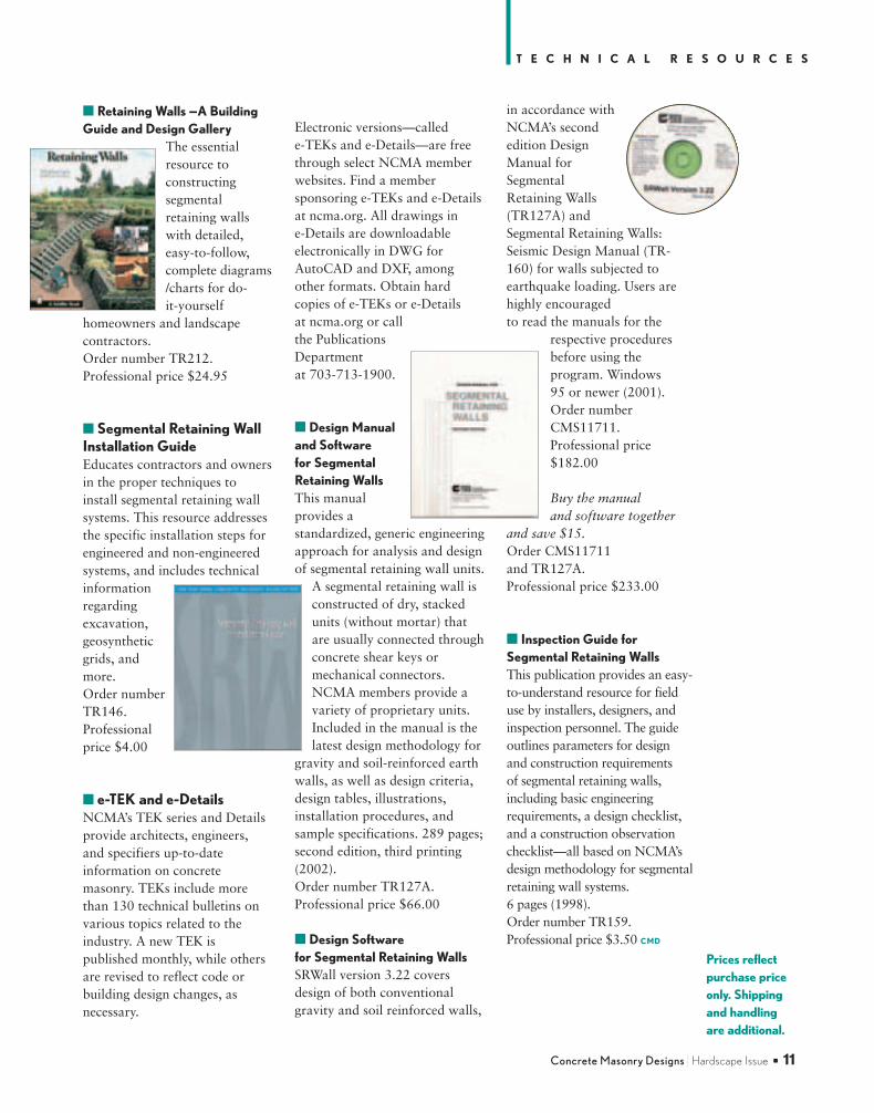
■ Retaining Walls —A BuildingGuide and Design Gallery
The essentialresource toconstructingsegmentalretaining wallswith detailed,easy-to-follow,complete diagrams/charts for do-it-yourself
homeowners and landscapecontractors. Order number TR212. Professional price $24.95
■ Segmental Retaining WallInstallation GuideEducates contractors and ownersin the proper techniques toinstall segmental retaining wallsystems. This resource addressesthe specific installation steps forengineered and non-engineeredsystems, and includes technicalinformationregardingexcavation,geosyntheticgrids, andmore. Order numberTR146. Professionalprice $4.00
■ e-TEK and e-DetailsNCMA’s TEK series and Detailsprovide architects, engineers,and specifiers up-to-dateinformation on concretemasonry. TEKs include morethan 130 technical bulletins onvarious topics related to theindustry. A new TEK ispublished monthly, while othersare revised to reflect code orbuilding design changes, asnecessary.
Electronic versions—called e-TEKs and e-Details—are freethrough select NCMA memberwebsites. Find a membersponsoring e-TEKs and e-Detailsat ncma.org. All drawings in e-Details are downloadableelectronically in DWG forAutoCAD and DXF, amongother formats. Obtain hardcopies of e-TEKs or e-Detailsat ncma.org or call the PublicationsDepartment at 703-713-1900.
■ Design Manualand Software for SegmentalRetaining WallsThis manualprovides astandardized, generic engineeringapproach for analysis and designof segmental retaining wall units.
A segmental retaining wall isconstructed of dry, stackedunits (without mortar) thatare usually connected throughconcrete shear keys ormechanical connectors.NCMA members provide avariety of proprietary units.Included in the manual is thelatest design methodology for
gravity and soil-reinforced earthwalls, as well as design criteria,design tables, illustrations,installation procedures, andsample specifications. 289 pages;second edition, third printing(2002). Order number TR127A. Professional price $66.00
■ Design Software for Segmental Retaining WallsSRWall version 3.22 coversdesign of both conventionalgravity and soil reinforced walls,
in accordance withNCMA’s secondedition DesignManual forSegmentalRetaining Walls(TR127A) andSegmental Retaining Walls:Seismic Design Manual (TR-160) for walls subjected toearthquake loading. Users arehighly encouraged to read the manuals for the
respective proceduresbefore using theprogram. Windows 95 or newer (2001). Order numberCMS11711. Professional price$182.00
Buy the manual and software together
and save $15. Order CMS11711 and TR127A. Professional price $233.00
■ Inspection Guide forSegmental Retaining WallsThis publication provides an easy-to-understand resource for fielduse by installers, designers, andinspection personnel. The guideoutlines parameters for design and construction requirements of segmental retaining walls,including basic engineeringrequirements, a design checklist,and a construction observationchecklist—all based on NCMA’sdesign methodology for segmentalretaining wall systems. 6 pages (1998).Order number TR159. Professional price $3.50 CMD
Prices reflect purchase priceonly. Shipping and handling are additional.
August 07 NCMA Hardscape Rev.:CM AUG HARDSCAPE 07 8/3/07 4:00 PM Page 11
8 / 0 712
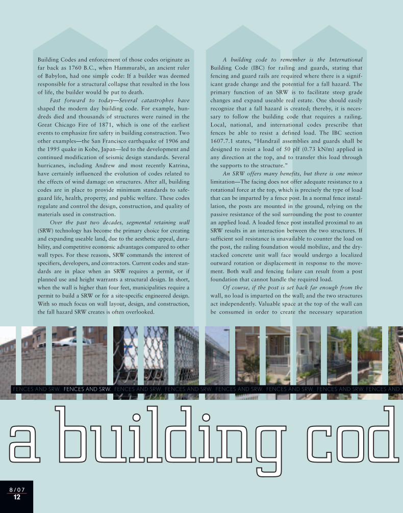
aa bbuuiillddiinngg ccooddee to rememberFENCES AND SRW. FENCES AND SRW. FENCES AND SRW. FENCES AND SRW. FENCES AND SRW. FENCES AND SRW. FENCES AND SRW. FENCES AND SRW
Building Codes and enforcement of those codes originate asfar back as 1760 B.C., when Hammurabi, an ancient rulerof Babylon, had one simple code: If a builder was deemedresponsible for a structural collapse that resulted in the lossof life, the builder would be put to death.
Fast forward to today—Several catastrophes have
shaped the modern day building code. For example, hun-dreds died and thousands of structures were ruined in theGreat Chicago Fire of 1871, which is one of the earliestevents to emphasize fire safety in building construction. Twoother examples—the San Francisco earthquake of 1906 andthe 1995 quake in Kobe, Japan—led to the development andcontinued modification of seismic design standards. Severalhurricanes, including Andrew and most recently Katrina,have certainly influenced the evolution of codes related tothe effects of wind damage on structures. After all, buildingcodes are in place to provide minimum standards to safe-guard life, health, property, and public welfare. These codesregulate and control the design, construction, and quality ofmaterials used in construction.
Over the past two decades, segmental retaining wall
(SRW) technology has become the primary choice for creatingand expanding useable land, due to the aesthetic appeal, dura-bility, and competitive economic advantages compared to otherwall types. For these reasons, SRW commands the interest ofspecifiers, developers, and contractors. Current codes and stan-dards are in place when an SRW requires a permit, or ifplanned use and height warrants a structural design. In short,when the wall is higher than four feet, municipalities require apermit to build a SRW or for a site-specific engineered design.With so much focus on wall layout, design, and construction,the fall hazard SRW creates is often overlooked.
A building code to remember is the International
Building Code (IBC) for railing and guards, stating thatfencing and guard rails are required where there is a signif-icant grade change and the potential for a fall hazard. Theprimary function of an SRW is to facilitate steep gradechanges and expand useable real estate. One should easilyrecognize that a fall hazard is created; thereby, it is neces-sary to follow the building code that requires a railing.Local, national, and international codes prescribe thatfences be able to resist a defined load. The IBC section1607.7.1 states, “Handrail assemblies and guards shall bedesigned to resist a load of 50 plf (0.73 kN/m) applied inany direction at the top, and to transfer this load throughthe supports to the structure.”
An SRW offers many benefits, but there is one minor
limitation—The facing does not offer adequate resistance to arotational force at the top, which is precisely the type of loadthat can be imparted by a fence post. In a normal fence instal-lation, the posts are mounted in the ground, relying on thepassive resistance of the soil surrounding the post to counteran applied load. A loaded fence post installed proximal to anSRW results in an interaction between the two structures. Ifsufficient soil resistance is unavailable to counter the load onthe post, the railing foundation would mobilize, and the dry-stacked concrete unit wall face would undergo a localizedoutward rotation or displacement in response to the move-ment. Both wall and fencing failure can result from a postfoundation that cannot handle the required load.
Of course, if the post is set back far enough from the
wall, no load is imparted on the wall; and the two structuresact independently. Valuable space at the top of the wall canbe consumed in order to create the necessary separation
August 07 NCMA Hardscape Rev.:CM AUG HARDSCAPE 07 8/3/07 4:00 PM Page 12
Concrete Masonry Designs I Hardscape Issue ■ 13
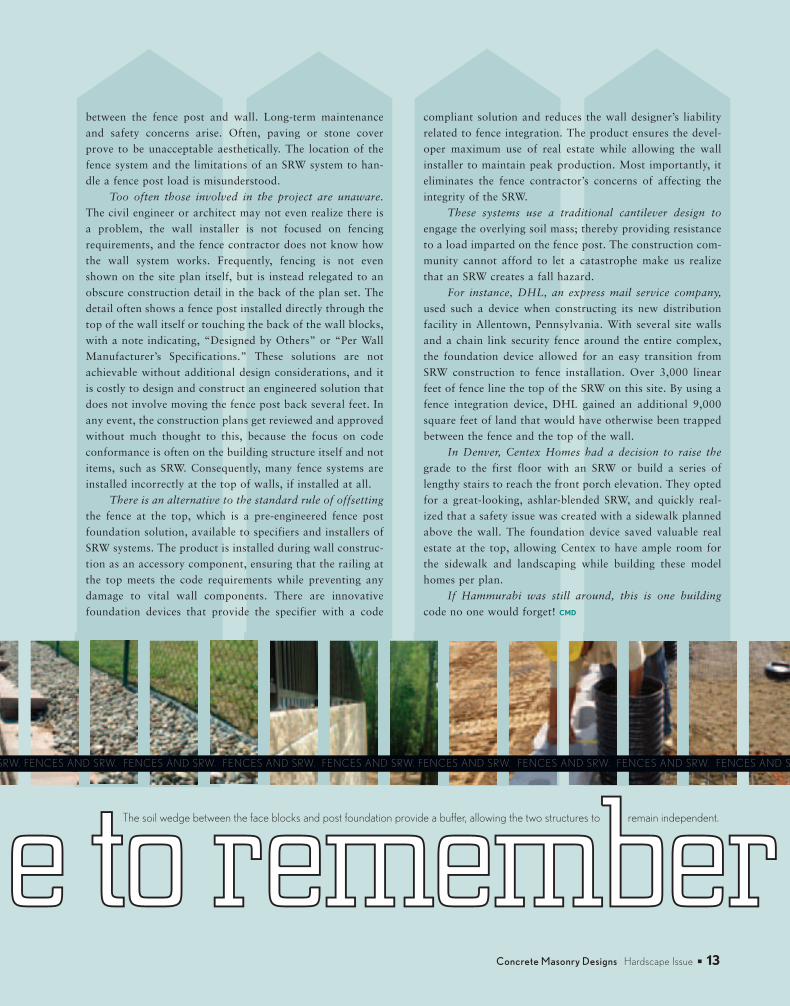
a building coddee ttoo rreemmeemmbbeerrThe soil wedge between the face blocks and post foundation provide a buffer, allowing the two structures to remain independent.
D SRW. FENCES AND SRW. FENCES AND SRW. FENCES AND SRW. FENCES AND SRW. FENCES AND SRW. FENCES AND SRW. FENCES AND SRW. FENCES AND SRW
between the fence post and wall. Long-term maintenanceand safety concerns arise. Often, paving or stone coverprove to be unacceptable aesthetically. The location of thefence system and the limitations of an SRW system to han-dle a fence post load is misunderstood.
Too often those involved in the project are unaware.
The civil engineer or architect may not even realize there isa problem, the wall installer is not focused on fencingrequirements, and the fence contractor does not know howthe wall system works. Frequently, fencing is not evenshown on the site plan itself, but is instead relegated to anobscure construction detail in the back of the plan set. Thedetail often shows a fence post installed directly through thetop of the wall itself or touching the back of the wall blocks,with a note indicating, “Designed by Others” or “Per WallManufacturer’s Specifications.” These solutions are notachievable without additional design considerations, and itis costly to design and construct an engineered solution thatdoes not involve moving the fence post back several feet. Inany event, the construction plans get reviewed and approvedwithout much thought to this, because the focus on codeconformance is often on the building structure itself and notitems, such as SRW. Consequently, many fence systems areinstalled incorrectly at the top of walls, if installed at all.
There is an alternative to the standard rule of offsetting
the fence at the top, which is a pre-engineered fence postfoundation solution, available to specifiers and installers ofSRW systems. The product is installed during wall construc-tion as an accessory component, ensuring that the railing atthe top meets the code requirements while preventing anydamage to vital wall components. There are innovativefoundation devices that provide the specifier with a code
compliant solution and reduces the wall designer’s liabilityrelated to fence integration. The product ensures the devel-oper maximum use of real estate while allowing the wallinstaller to maintain peak production. Most importantly, iteliminates the fence contractor’s concerns of affecting theintegrity of the SRW.
These systems use a traditional cantilever design to
engage the overlying soil mass; thereby providing resistanceto a load imparted on the fence post. The construction com-munity cannot afford to let a catastrophe make us realizethat an SRW creates a fall hazard.
For instance, DHL, an express mail service company,
used such a device when constructing its new distributionfacility in Allentown, Pennsylvania. With several site wallsand a chain link security fence around the entire complex,the foundation device allowed for an easy transition fromSRW construction to fence installation. Over 3,000 linearfeet of fence line the top of the SRW on this site. By using afence integration device, DHL gained an additional 9,000square feet of land that would have otherwise been trappedbetween the fence and the top of the wall.
In Denver, Centex Homes had a decision to raise the
grade to the first floor with an SRW or build a series oflengthy stairs to reach the front porch elevation. They optedfor a great-looking, ashlar-blended SRW, and quickly real-ized that a safety issue was created with a sidewalk plannedabove the wall. The foundation device saved valuable realestate at the top, allowing Centex to have ample room forthe sidewalk and landscaping while building these modelhomes per plan.
If Hammurabi was still around, this is one building
code no one would forget! CMD
August 07 NCMA Hardscape Rev.:CM AUG HARDSCAPE 07 8/3/07 4:00 PM Page 13
8 / 0 714
Concrete Masonry’s AIA ContinuingEducationLearning Program
Learning Units Reporting Form Return this form to theNational Concrete MasonryAssociation. Only originalforms are acceptedfor learning unit credit.
Return forms before August2008 to receive learning unitcredits.
I am a non-AIA architect ordesign professional. Please mail me a certificate stating that thelearning units earned can beused to fulfill other continuingeducation requirements.
Send completed Report Form to: AIA CES, NationalConcrete Masonry Association,13750 Sunrise Valley Drive,Herndon, VA 20171-4662.If you have questions, please contact NCMA at 703-713-1900.
August 2007 Check here to request a catalog of concrete masonry technical literature.
AIA Questions: (Check the correct answer)
1. Segmental retaining wall systems can be used for:■■ Structural grade changes.■■ Converting unusable sloped land to level surfaces.■■ Water retention and drainage.■■ Both A and B.
2. Sand soils are discouraged to be used as backfill in SRW applications.■■ True■■ False
3. An acceptable method to stabilize a SRW system is:■■ Add water to the soils.■■ Use geogrid to stabilize the soil mass behind the wall.■■ Use clay as a backfill material.■■ All of the above.
4. When placing a fence system at the top of a segmental retaining wall, which of the following is not an acceptable practice?■■ Placing the fence structure a minimum of 38 inches away from the wall face.■■ Using a sleeve or tube during wall construction.■■ Augering through the geogrid after wall construction.■■ Requiring the fence system to meet building code specifications.
5. Passive soil resistance at the top of the wall cannot be achieved to resist loads imparted by a fence system.■■ True■■ False
AIA Member Information:
NAME
ADDRESS
CITY STATE/PROVINCE POSTAL CODE
PHONE FAX
E-MAIL ID NUMBER
I certify that the above information is true and accurate to the best of my knowledge. I have complied with the AIA Continuing Education Guidelines.
SIGNATURE DATE
August 07 NCMA Hardscape Rev.:CM AUG HARDSCAPE 07 8/3/07 4:00 PM Page 14
Concrete Masonry Designs I Hardscape Issue ■ 15
D E T A I L O F T H E M O N T H
Proper fence integration with a
segmental retaining wall (SRW) is
often misunderstood or over-
looked during the design and con-
struction of an SRW. First of all, a
fence and a wall are two indepen-
dent structures. To design one
without considering the require-
ments of the other can create con-
cerns. Here are some general in-
dustry guidelines when planning
for a fence above an SRW:
Building codes typically re-
quire a fence or guard rail,
where there is the combination of
a significant grade change and the
potential for it becoming a fall
hazard. The construction of an
SRW often triggers the enforce-
ment of this code, due to its ability
to facilitate vertical grade changes
and create useable space accessible
by the public.
SRW are made up of several
components, including the
concrete block units, drainage
gravel, geosynthetic reinforcement
(geogrid), and compacted soil. In-
stalling a fence in the traditional
manner can often affect the in-
tegrity of these wall components.
Building codes require that a
fence structure be able to re-
sist a defined load applied at the
most critical point, which is the
top of the fence post. Because
SRW concrete block units are dry-
stacked, they are susceptible to lo-
calized overturning near the top of
the wall.
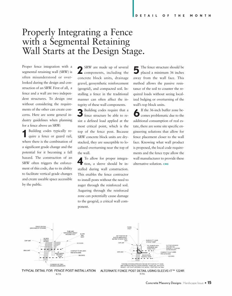
To allow for proper integra-
tion, a sleeve should be in-
stalled during wall construction.
This enables the fence contractor
to install posts without the need to
auger through the reinforced soil.
Auguring through the reinforced
zone can potentially cause damage
to the geogrid, a critical wall com-
ponent.
The fence structure should be
placed a minimum 36 inches
away from the wall face. This
method allows the passive resis-
tance of the soil to counter the re-
quired loads without seeing local-
ized bulging or overturning of the
wall’s top block units.
If the 36-inch buffer zone be-
comes problematic due to the
additional consumption of real es-
tate, there are some site specific en-
gineering solutions that allow for
fence placement closer to the wall
face. Knowing what wall product
is proposed, the local code require-
ments and the fence type allow the
wall manufacturer to provide these
alternative solution. CMD
Properly Integrating a Fence with a Segmental Retaining Wall Starts at the Design Stage.
1
2
3
4
5
6
August 07 NCMA Hardscape Rev.:CM AUG HARDSCAPE 07 8/3/07 4:00 PM Page 15
13750 Sunrise Valley DriveHerndon, VA 20171-4662
H a r d s c a p e I s s u e I August 2007
MasonryMasonry
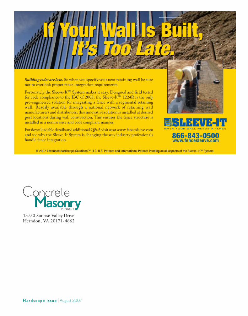
© 2007 Advanced Hardscape Solutions™ LLC. U.S. Patents and International Patents Pending on all aspects of the Sleeve-It™ System.
If Your Wall Is Built, It’s Too Late.
Building codes are law. So when you specify your next retaining wall be sure not to overlook proper fence integration requirements.Fortunately the Sleeve-It™ System makes it easy. Designed and field tested for code compliance to the IBC of 2003, the Sleeve-It™ 1224R is the only pre-engineered solution for integrating a fence with a segmental retaining wall. Readily available through a national network of retaining wall manufacturers and distributors, this innovative solution is installed at desired post locations during wall construction. This ensures the fence structure is installed in a noninvasive and code compliant manner.For downloadable details and additional Q&A visit us at www.fencesleeve.com and see why the Sleeve-It System is changing the way industry professionals handle fence integration. 866-843-0500
www.fencesleeve.com
August 07 NCMA Hardscape Rev.:CM AUG HARDSCAPE 07 8/3/07 4:00 PM Page C4