automation of the process of troubleshooting of ship systems
TRANSCRIPT

418
Automation of the Process of Troubleshooting of Ship Systems
Oksana Tereshchenkova, Kostyantyn Kondrashov Kherson State Maritime Academy, 20, Ushakova str., Kherson, Ukraine
Abstract Ship automation is a process in which the control functions of a ship and its equipment,
previously performed by a person, are transferred to an instrument and technical devices. The
article shows the ability to automate the search for the causes of malfunctions. Through the
use of an observer with a DSS, information is processed in real time from the electronic unit
of the ship's diagnostic system. The example shows how, in the event of errors or
malfunctions registered by the ship's diagnostic system, the program can independently offer
a search card for the malfunction that has occurred, accurate to a failed sensor or electrical
circuit. A method for troubleshooting by using diagnostic matrices is described.
Keywords1 object of diagnostics (OOD), complex technical system (CTS), decision maker (DM),
alarm monitoring system (AMS), decision support system (DSS).
1. Introduction
Any modern ship is a highly complex automated system for a specific purpose. To ensure the fulfillment of the assigned task, all the mechanisms and devices of the vessel must perform each of its
specific functions. And only the well-coordinated work of all the systems of the vessel allows to
ensure both the survivability of the vessel and the safety of all crew members. Here, one of the most important roles in ensuring safety is played by the ship's alarm monitoring system (AMS), the main
task of which is to monitor the stable operation of all ship systems and warn the operator in case of
any malfunction. Destruction or failure in work caused by one reason or another, almost inevitably
terminate the functioning of any technical system. Catastrophic accidents often occur, i.e. there is always a risk of an accident.
The statistics of ship equipment malfunctions shows that with the growth of automation and
computerization of processes, the growth of breakdowns of ship systems and mechanisms also grows. In addition, in the field of operation and maintenance of ship equipment, one should take into account
the need to find solutions to reduce the negative impact of the so-called “human factor”, which is
spelled out in IMO resolution A.884 (21). The tasks of assessing the risks of shipboard complex technical system (CTS) in the transition
from the assessment of reliability and safety in a deterministic setting to an assessment in a
probabilistic setting are relevant today. Processes of changes in the technical state of shipboard (CTS)
are difficult to predict. The reliability and performance of such systems depend on factors determined by their design, production and operating conditions.
At present, the theory of survivability is at such a stage of development when the basic concepts
and definitions have not yet been formed; there is no consensus on what is survivability, what is the scope of this concept. There are practically no models of the survivability of ship technical systems
that have been approved by long-term practical use. The wide variety of known indicators of
survivability rather indicates a lack of clarity in resolving this issue than its elaboration. There are no
specific methodological developments on the issue of which ship technical systems should be assessed, standardized and ensured survivability. Until now, a developed theory has not been created
IT&I-2020: Information Technology and Interactions, 2-3 December, 2020, Kyiv, Ukraine
EMAIL: [email protected] (A. 1); [email protected] (A. 2)
ORCID: 0000-0002-0023-5550 (A. 1); 0000-0003-1352-6098 (A. 2)
©️ 2020 Copyright for this paper by its authors.
Use permitted under Creative Commons License Attribution 4.0 International (CC BY 4.0).
CEUR Workshop Proceedings (CEUR-WS.org)
419
that would contain, like the theory of reliability, general technical results that allow one to study this property, evaluate it quantitatively and develop practical recommendations for the designer of
complex systems to ensure survivability.
Development of a classification of technical diagnostics tasks, analysis of the forms of
organization of test and functional diagnosis systems, as well as the development of technical diagnostics procedures and substantiation of application methods logical algorithms for finding the
causes of malfunctioning of complex technical systems with discrete characteristics were studied by
such authors as: P.P. Parkhomenko, E. S. Soghomonyan, V. V. Klyuev. [1,2] Research in the development and testing of diagnostic devices and expert systems for monitoring the main ship
engines (diesels and gas turbine engines) and auxiliary ship equipment, the strategy of servicing ship
equipment according to the actual technical condition was studied by E.S. Golub, G.Sh. Rosenberg, E.Z. Madorsky. [3-5]
Most of both domestic and foreign authors consider only individual components and their
parameters. [6-16]
2. Problem statement
The variety and breadth of system analysis allows the use of mathematical modeling methods as
well as elements of information theory, decision making, etc.
Technical diagnostics covers all issues related to the assessment of the state of technical objects.
Consider ship systems and complexes, as well as a diagnostic system that monitors their operational state as technical objects that can be described mathematically.
Monitoring complex technical systems allows, with human participation, to monitor and
continuously monitor the state of the operating system and, with the involvement of the intellectual abilities of a person (operator), predict changes in its state. At the same time, banks of data and
knowledge are used, and in some cases, data from periodically conducted diagnostic checks, which
make it possible to clarify the place of occurrence of defects and the causes of malfunctions. The information base for the control and diagnostic procedures is a set of physical parameters.
The process of assessing the state of a technical object includes the perception and processing of
primary information from the technical object, the state of which is being assessed, the analysis of
secondary information about the state of the object and decision making (DM). By now, automation has become a huge area of human knowledge, the value of which lies not only
in their practical use, but also in the worldview aspect. For a more complete understanding of the
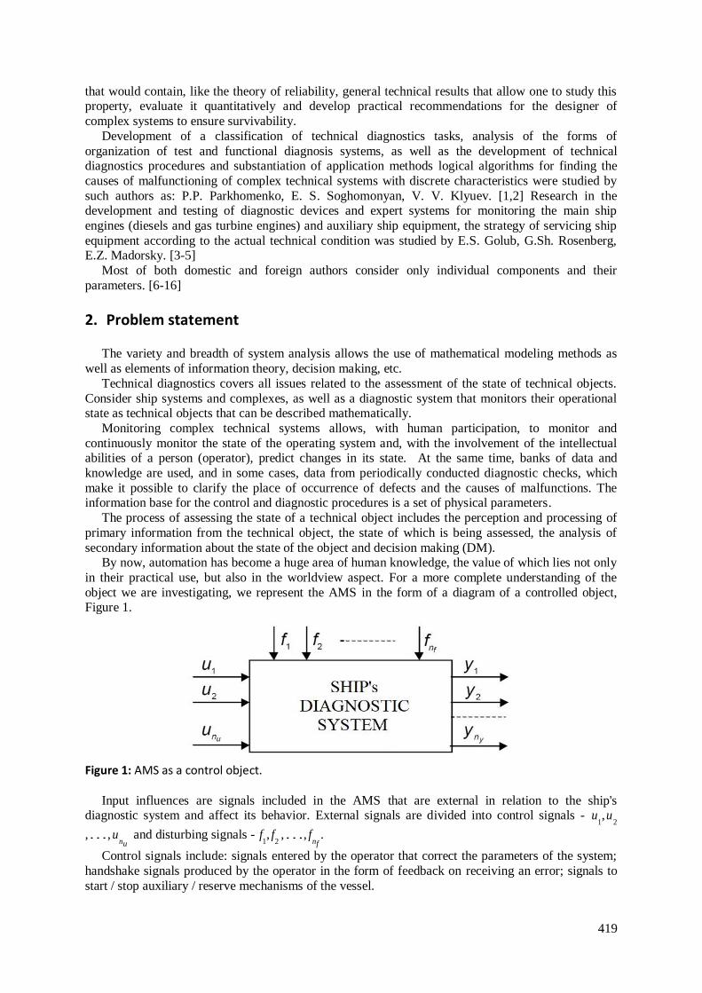
object we are investigating, we represent the AMS in the form of a diagram of a controlled object, Figure 1.
Figure 1: AMS as a control object.
Input influences are signals included in the AMS that are external in relation to the ship's diagnostic system and affect its behavior. External signals are divided into control signals - u
1,u
2
,…,unu
and disturbing signals - f1, f
2 ,…, fnf
.
Control signals include: signals entered by the operator that correct the parameters of the system;
handshake signals produced by the operator in the form of feedback on receiving an error; signals to
start / stop auxiliary / reserve mechanisms of the vessel.
420
Disturbing signals include signals from controlled parameters of ship systems. Output variables, or variables, that allow describing some aspects of the behavior of ship systems
that are of interest to decision makers about the possibility of their further functioning - y1, y
2 ,..., y ny .
State variables, or intermediate variables x1, x
2 ,..., xnx , characterizing the reference states of
controlled systems.
For the convenience of operating with multidimensional quantities, we represent the set of control
variables in the form of a control vector �⃗� . In a similar way, we introduce the concepts of a
disturbance vector 𝑓 , an output vector 𝑦 , and a state vector 𝑥 :
�⃗� = (
𝑢1
𝑢2
…𝑢𝑛𝑢
) 𝑓⃗⃗⃗ = (
𝑓1𝑓2…𝑓𝑛𝑓
) 𝑦 = (
𝑦1
𝑦2
…𝑦𝑛𝑦
) 𝑥 = (
𝑥1
𝑥2
…𝑥𝑛𝑥
)
(1)
The set of all values that the vector �⃗� can take at time t forms a control space. Similarly, we
introduce the notions of a perturbation space, an output space, and a state space.
I.e. at any time moment t the state of the system is a function of the initial state 𝑥 (t0) and vectors
�⃗� (t0,t) and 𝑓 (t0,t). If it is known how these vectors changed on the interval [t0,t], then the state of the
system 𝑥 (t) can be uniquely determined:
𝑥 (𝑡) = 𝐹{𝑥 (𝑡𝑜), �⃗� (𝑡𝑜 , 𝑡), 𝑓 (𝑡𝑜 , 𝑡)} (2)
The output vector at time t is a function of the same variables:
𝑦 (𝑡) = {𝑥 (𝑡𝑜), �⃗� (𝑡𝑜, 𝑡), 𝑓 (𝑡𝑜 , 𝑡)} (3)
The state of the system separates the future from the past, so that the state contains all the information needed to determine the object's response to an arbitrary input signal. The concept of a
state is the basic initial concept and, therefore, cannot be defined more fully than, for example, the
word set in mathematics. The most that can be done is to formulate the properties that a system should have, the behavior of which corresponds to the concept of a state.
The main property of the state is that its future values do not depend on the nature of the system
reaching its current state. The state of the system at a given time, as well as the current and future
values of its inputs, uniquely determines the present and future values of its state and outputs. Quick troubleshooting allows you to establish the causes of failures and restore the functionality of
electrical equipment at minimal cost. Troubleshooting of relatively simple electrical equipment does
not cause any particular difficulties, and to identify malfunctions of complex electrical equipment and complex control circuits, it is required to draw up troubleshooting algorithms to determine the most
rational sequence of operations. At the same time, the minimum time and money spent on searching
should be ensured. If we imagine that a ship's complex of systems is a complex mechanism consisting of many separate modules, then it becomes necessary to coordinate all such modules to maintain the
system in working order. For these purposes, we will consider a scheme for maintaining the ship's
system in working order using an observer and DSS, Figure 2. During the operation of the vessel, the
automatic mode of searching for failed equipment can be provided using an observer and DSS: 1. The ship alarm system provides cyclic polling of sensors that measure the parameters of ship
systems.
2. The measurement result of each parameter is compared with the corresponding reference values stored in the memory of the AMS and the observer. As a result of the comparison, the parameter is
discretized, i.e. the measured analog value of the parameter is replaced with a discrete one in
accordance with the same coding system that was used when filling the reference matrix. After the completion of each cycle of interrogation of sensors and comparison with the settings of their signals,
a combination of discrete parameter values is obtained. It is compared with the reference
combinations recorded in the columns of the diagnostic matrix. Comparison is performed bit by bit as
long as the bit values match. At the first mismatch, the transition to the next column of the matrix occurs.

421
Figure 2: AMS with observer and DSS
3. The comparison continues until a column is found whose combination completely coincides with the combination of instantaneous parameter values. Its number corresponds to the number of the requested emergency. According to him the operator is given a diagnosis, as well as recommendations for possible causes of malfunctions and algorithms for their elimination.
The algorithm of the diagnostic system with the inclusion of an observer and DSS is shown in Figure 3: if a malfunction occurs (an error code is read), the observer with the DSS will automatically offer the operator recommendations for elimination. The assessment of possible causes of malfunctions is taken from the DSS knowledge base and is determined by the opinion of experts; if the cause of the malfunction indicated by the experts turned out to be inappropriate, the decision maker enters the signs of malfunction and the program into the DSS, calculates the possible cause of the malfunction using the calculation method and also gives the operator recommendations for its elimination; if this reason does not help in solving the problem, then the operator is given the opportunity to select the possible causes for this malfunction from the knowledge base, where they are arranged in order of priority, according to experts. The decision support system (DSS) forms and proposes decisions on the need for technical interventions for each specific malfunction, taking into account all factors. The decision adopted in the DSS is implemented by the operator (DM) in the workflow. The effectiveness of technical actions on the object of diagnosis (faulty system) is determined in the feedback subsystem. The feedback subsystem is a tracking device that provides comparability of results based on diagnostic information. In this sense, feedback has a unique ability of a regulator, which allows accumulating statistics on decisions made and results obtained.
To take into account the signs that show the priority of one of the causes of the malfunction, we will use the technical calculation method. To represent the object of diagnostics in the form of a "black box" we set: a set of input influences from stimulating devices and the external environment; set of all output (diagnostic) parameters; set of all structural parameters of the object. The problem of finding a malfunction is formulated as follows: from the given values of the diagnostic parameters, S1,S2,…, Sm, determine the current values of all structural parameters X1,X2 ...,Xm, if the functional dependencies between each diagnostic signal and the structural parameters are known:
𝑺𝟏 = 𝝋𝟏(𝑿𝟏, 𝑿𝟐 … . , 𝑿𝒎) 𝑆2 = 𝜑2(𝑋1, 𝑋2 … . , 𝑋𝑚) …………………………….. 𝑆𝑚 = 𝜑𝑚(𝑋1, 𝑋2 … . , 𝑋𝑚)
(4)

422
Figure 3: Fault elimination algorithm using DSS
This system of equations is, in fact, a mathematical model of the diagnostic object, which has m
structural parameters and n diagnostic ones. However, the practical use of such an analytical model is still limited.
This is due to the fact that: the type of functions for the majority of ship systems and their units has not yet been established; if the function does not satisfy the conditions of continuity and differentiability for each argument, then the solution of the system causes great mathematical difficulties; many diagnostic parameters, in principle, cannot be expressed as analytical functions. The most widespread for the relationship between possible technical conditions (malfunctions) and diagnostic parameters are diagnostic matrices.
The synthesis of such matrices is carried out in a certain sequence: first, a complete list of possible faults is drawn up; for each malfunction, a list of possible causes of these malfunctions is compiled; a list of symptoms is compiled for each possible cause; an infinite set of technical states of an object is replaced by a finite set, each of which is associated with a certain malfunction. The diagnostic matrix, in fact, is a form of recording the system of equations for the technological state of the ship's system or its unit. Each column of the matrix corresponds to a certain fault Хi , table 1.

423
Table 1 Diagnostic matrix
Diagnostic parameters Si
Possible malfunctions
X1 X2 …… Xn
S1 X11 X21 …… Xn1 S2 X12 X22 …… Xn2 …… …… …… …… …… Sm X1m X2m Xnm
Each i-th malfunction has a specific diagnostic parameter that takes two values:
𝑆𝑖 = {0 − 𝑖𝑛 𝑡ℎ𝑒 𝑎𝑏𝑠𝑒𝑛𝑐𝑒 𝑜𝑓 𝑚𝑎𝑙𝑓𝑢𝑛𝑐𝑡𝑖𝑜𝑛
1 − 𝑖𝑓 𝑡ℎ𝑒𝑟𝑒 𝑖𝑠
(5)
The diagnostic task in this case is formulated as follows: according to the given values of the
diagnostic parameters S1 , S2…, Sm, obtained during the diagnostic examination, determine the values of the structural parameters X1 , X2... Xm, at the time of verification, if the functional dependencies are known (symptoms belonging to a particular malfunction ) between diagnostic and all structural parameters in the form of a system of equations or a matrix.
The solution to the problem consists in transforming a set of diagnostic parameters into a set of structural parameters, since it is the values of the diagnostic parameters that are known when making a diagnosis.
The troubleshooting process based on the diagnostic object model, expressed in the form of a diagnostic matrix, consists of the following stages: by means of appropriate measurements, the values of all diagnostic parameters S1 , S2…, Sm are established; the values of diagnostic parameters are substituted into the system of equations; the values of all fault functions are calculated, and if
𝑋𝑖 {= 1 − 𝑡ℎ𝑒𝑟𝑒 𝑖𝑠 𝑎𝑛 𝑖 − 𝑡ℎ 𝑚𝑢𝑙𝑓𝑢𝑛𝑐𝑡𝑖𝑜𝑛
≠ 1 − 𝑓𝑢𝑛𝑐𝑡𝑖𝑜𝑛𝑎𝑙 𝑢𝑛𝑑𝑒𝑓𝑖𝑛𝑒𝑑
(6)
The feasibility of the process of finding a malfunction should be understood as obtaining an unambiguous answer about the technical state of an object within the framework of the accepted assumptions about possible states in the presence of any combination of values of diagnostic parameters that does not contradict physical representations, i.e. the set of structural parameters (faults) of the object would be unambiguous.
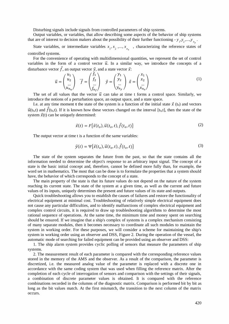
However, the method of constructing the matrix does not guarantee that the selected set of possible faults is not redundant. The redundancy of such data leads to an increase in the total time and complexity of diagnostics, while the logical process of finding a malfunction becomes more complicated, and the search time increases. For this, we add data on the diagnostic symptoms of each malfunction to the matrix. The maximum number of matching features is selected as the optimality criteria. For example, in the event of a malfunction in the air conditioning system - SUCTION PRESSURE IS EXCESSIVELY LOW, the opinions of experts on possible elimination in the DSS are reflected as follows, Figure 4.
The operator (DM) carries out actions with the maximum offered percentage, i.e. checks the most likely cause, according to experts. If the specified reason turned out to be incorrect, then the decision maker adds to the DSS a number of attributes accompanying the situation that has occurred, Table 2.
Attributes of malfunction: s1 – Filter drier is frozen; s2 – The current of compressor is lower than normal; s3 – The unit can’t reach set point; s4 – EV is excessively frozen. Supply temp. is almost same as return temp.; s5 – The valve no click if test it by magnet; s6 - Visible ice on the evaporator coil; s7 - Condenser pressure is low; s8 - Compressor start and at once stopped by high pressure; s9 - Evaporator coil is frozen; s10 - No visible Freon flow in sight glass; s11 - The coil is not warm if touch it; s12 - Controller give same errors.
We divide the set of diagnostic symptoms of the original matrix into groups, including columns with the same combinations of 0 and 1. We identify the features that have 1 in all rows, they do not carry any information and can be excluded. In our example, these are symptoms s3 and s10.
424
Figure 4: DSS screen form. Expert suggestions.
Then we write down expressions for all possible malfunctions, indicating diagnostic symptoms
that have the value 1. As a result, the malfunction symptoms are distributed as follows:
X1= X2 = X3 = X5 = X6 = X7= X8= X9 = X10 = X11 = s3^s10 X4 = s3^s5^ s7^s10^ s11
Since the detection of faults X1, X2 , X3 , X5 , X6 , X7, X8, X9 , X10 , X11 is carried out according to
symptoms S3 and S10, these faults can be considered as one. The object is operational only when all possible malfunctions are absent.
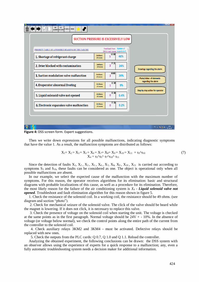
In our example, we select the expected cause of the malfunction with the maximum number of symptoms. For this reason, the operator receives algorithms for its elimination: basic and structural diagrams with probable localizations of this cause, as well as a procedure for its elimination. Therefore, the most likely reason for the failure of the air conditioning system is X4 - Liquid solenoid valve not opened. Troubleshoot and fault elimination algorithm for this reason shown in figure 5.
1. Check the resistance of the solenoid coil. In a working coil, the resistance should be 49 ohms. (see diagram and section “photo”).
2. Check for mechanical seizure of the solenoid valve. The click of the valve should be heard while the magnet is lowering. If it does not click, it is necessary to replace this valve.
3. Check the presence of voltage on the solenoid coil when starting the unit. The voltage is checked at the same points as in the first paragraph. Normal voltage should be 24V + - 10%. In the absence of voltage (or voltage below normal), we check the control points along the entire path of the current from the controller to the solenoid coil.
4. Check auxiliary relays 3KM2 and 3KM4 - must be activated. Defective relays should be replaced with new ones.
5. Check the outputs from the PLC cards: Q 0.7, Q 1.0 and Q 1.1. Reload the controller. Analyzing the obtained experiment, the following conclusions can be drawn: the DSS system with
an observer allows using the experience of experts for a quick response to a malfunction; any, even a fully automatic troubleshooting system needs a decision maker for additional information.
(7)
425
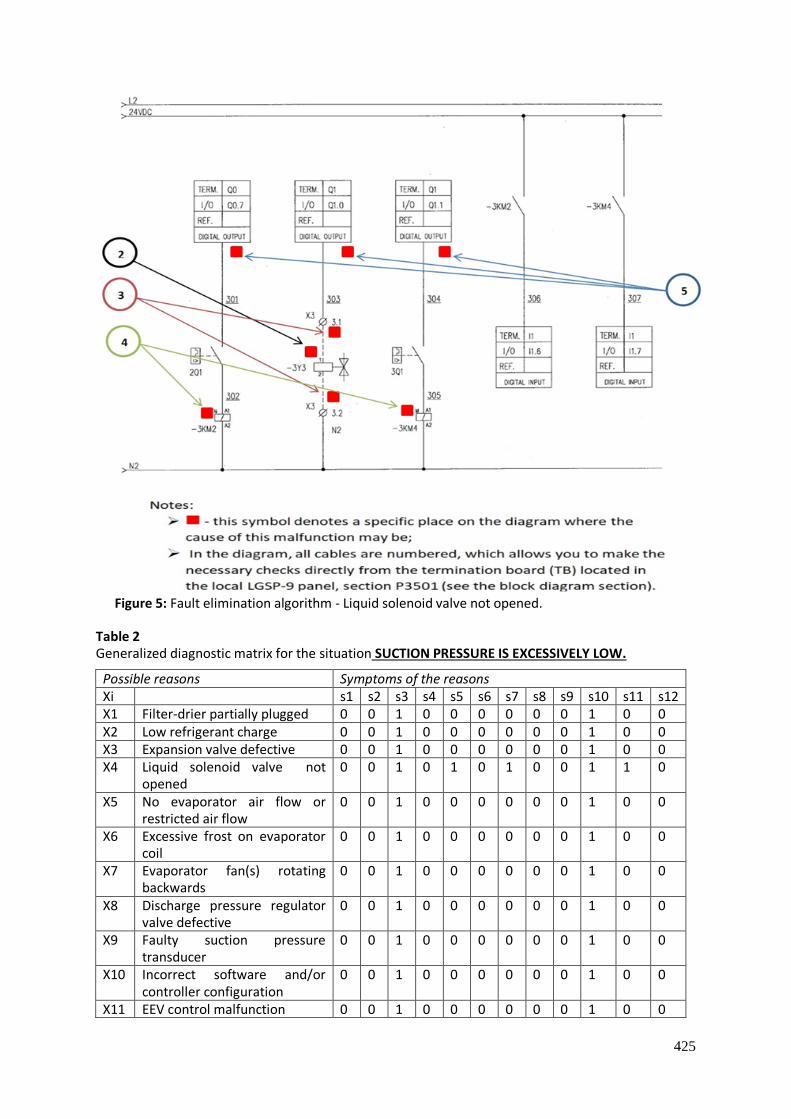
Figure 5: Fault elimination algorithm - Liquid solenoid valve not opened.
Table 2 Generalized diagnostic matrix for the situation SUCTION PRESSURE IS EXCESSIVELY LOW.
Possible reasons Symptoms of the reasons Xi s1 s2 s3 s4 s5 s6 s7 s8 s9 s10 s11 s12 X1 Filter-drier partially plugged 0 0 1 0 0 0 0 0 0 1 0 0 X2 Low refrigerant charge 0 0 1 0 0 0 0 0 0 1 0 0 X3 Expansion valve defective 0 0 1 0 0 0 0 0 0 1 0 0 X4 Liquid solenoid valve not
opened 0 0 1 0 1 0 1 0 0 1 1 0
X5 No evaporator air flow or restricted air flow
0 0 1 0 0 0 0 0 0 1 0 0
X6 Excessive frost on evaporator coil
0 0 1 0 0 0 0 0 0 1 0 0
X7 Evaporator fan(s) rotating backwards
0 0 1 0 0 0 0 0 0 1 0 0
X8 Discharge pressure regulator valve defective
0 0 1 0 0 0 0 0 0 1 0 0
X9 Faulty suction pressure transducer
0 0 1 0 0 0 0 0 0 1 0 0
X10 Incorrect software and/or controller configuration
0 0 1 0 0 0 0 0 0 1 0 0
X11 EEV control malfunction 0 0 1 0 0 0 0 0 0 1 0 0
426
3. Conclusions
For ship equipment with a wide range of operating conditions and modes and significant values of the resource variation coefficients, group probabilistic assessments of reliability and durability are insufficient for timely adoption by personnel of measures to prevent failures and accidents, since they do not provide an individual assessment of the actual state of a particular unit, machine, mechanism or piece of equipment.
Through the use of an observer with a DSS, information is processed in real time from the electronic unit of the ship's diagnostic system. Based on the continuously received information, the DSS displays diagnostic information about the state of the ship's operating systems in a user-friendly form. In the event of errors or malfunctions registered by the ship diagnostic system, the program can independently offer a search card for the malfunction that has occurred with an accuracy of a failed sensor or electrical circuit.
4. References
[1] P.P. Parkhomenko, Fundamentals of technical diagnostics / P.P. Parkhomenko, E.S. Soghomonyan - Moscow: Energiya, 1981 .-- 320 p.
[2] Technical means of diagnostics. Handbook ed. V.V.Klyuev. M .:Mashinostroenie, 1989.—672 p. [3] Dranitsyn, SN Complex system of maintenance and repair of ships. Basic guide. RD 31.20.50–
87. M./S.N. Dranitsyn, G.Sh. Rosenberg, E.S. Golub, E.Z. Madorsky, A.N. Neelov - L .: Mortekhinformreklama, 1988 .-- 218 p.
[4] E.S. Golub, Diagnostics of ship technical equipment. Handbook / E.S. Golub, E.Z. Madorsky, G.Sh. Rosenberg - M .: Transport, 1993 .-- 150 p.
[5] Diagnostics and monitoring of the state of complex technical systems: a tutorial / N. A. Makhutov., V. N. Permyakov, R. S. Akhmetkhanov, etc. - Tyumen: TIU, 2017 - 632 p. ISBN 978-5-9961-1433-7.
[6] A.A. Ravin Simulation modeling of failures of automation elements of a stochastic object / Materials of the 4th All-Russian Interdisciplinary Scientific and Technical Conference "Actual Problems of Marine Energy". SPb .: 2015 - p. 117-178.
[7] S.S. Voronin, E.A. Maklakova, A.S. Maklakov, V.R. Gasiyarov, The determination of energy-power parameters of hot plate mill mechatronic system, Procedia Engineering. 129 (2015) 51-56.
[8] E.A. Maklakova, A.S. Maklakov, V.R. Gasiyarov, S.S. Voronin, The work roll bending control system of the hot plate rolling mill, Procedia Engineering. 129 (2015) 37-41.
[9] A.S. Maklakov, E.A. Maklakova, EMC Analysis of 18-pulse ɫonnection ɫircuit based on 3L-AFE with SHEPWM, Russian Internet Journal of Industrial Engineering. 1 (2016) 66-73.
[10] B. Pourbabaee, N. Meskin, K. Khorasani. Sensor fault detection, isolation, and identification using multiple-modelbased hybrid Kalman filter for gas turbine engines. IEEE Transactions on Control Systems Technology. 2016; 24: 1184-200.
[11] I.Roumeliotis, N.Aretakis, A.Alexiou Industrial Gas Turbine Health and Performance Assessment With Field Data. Journal of Engineering for Gas Turbines and Power. 2017; 139: 051202.
[12] E.Tsoutsanis, N. Meskin, M. Benammar, K. Khorasani. A dynamic prognosis scheme for flexible operation of gas turbines. Applied Energy. 2016; 164: 686-701.
[13] E. Mohammadi, M. Montazeri-Gh A fuzzy-based gas turbine fault detection and identification system for full and part-load performance deterioration. Aerospace Science and Technology. 2015; 46: 82-93
[14] M.A. Zaidan, R.F. Harrison, AR. Mills, PJ. Fleming. Bayesian hierarchical models for aerospace gas turbine engine prognostics. Expert Systems with Applications. 2015; 42: 539-53.
[15] M.A. Zaidan, A.R. Mills, R.F. Harrison, P.J. Fleming. Gas turbine engine prognostics using Bayesian hierarchical models: A variational approach. Mechanical Systems and Signal Processing. 2016; 70: 120-40.
[16] B. Bole, L.Tang, K.Goebel, G.Vachtsevanos. “Adaptive Load-Allocation for Prognosis-Based Risk Management”. Prognostics and Health Management Conference, 2011