automation+robotik – portale und portalroboter and gantry robot.pdf · 5·18857·2004·2 °...
TRANSCRIPT
5·18
857·
2004
·2°
Art.-
Nr.
B5-
30-0
010-
209
/200
4
Automation+Robotik – Portale und PortalroboterAutomation+Robotics – Gantries and Gantry robots
Automatisme et robotique – Portiques et Robots-portiques
000_U1ohneRuecken 26.08.2004 13:36 Uhr Seite 3
InhaltsverzeichnisList of ContentsSommaire
Änderungen vorbehalten / Right of modifications reserved / Modifications techniques réservées 3
5·18
858
·200
4·2
°
Seite Page Page
FIBRO – Tradition und moderne TechnikFIBRO – The latest technology – with a tradition of service 4/5FIBRO – Tradition et technique moderne
Übersicht PortalprogrammOverview of gantry range 6/7Vue d’ensemble de la gamme de portique
Allgemeine BeschreibungGeneral description 8–13Description générales
AusführungsvariantenConstruction variants 14Variantes de construction
Linearachse vertikal Typ LV Linear axis, vertical Type LV 15–47Axe linéaire vertical Type LV
Linearachse horizontal Typ LHLinear axis, horizontal Type LH 49–85Axe linéaire horizontal Type LH
Kreuzlaufwagen Typ KLCross carriage Type KL 87–123Chariot croisé Type KL
Portalroboter Typ KOPGantry robot Type KOP 125–153Robot à portique Type KOP
Portalroboter mit Ausleger Typ KOAGantry robot with cantilever Type KOA 155–183Robot à portique avec cantilever Type KOA
Zubehör und SicherheitssystemeAccessories and safety systems 185–187Accessoires et systèmes de sécurité
Produktübersicht/KatalogeProduct range/Cataloges 188/189Vue du programme/Catalogues
VertreterverzeichnisList of representatives 190/191Liste de représentants
003_inhalt 26.08.2004 13:36 Uhr Seite 1
FIBRO – Tradition und moderne TechnikFIBRO – The latest technology – with a tradition of serviceFIBRO – Tradition et technique moderne
FIBRO works atWeinsberg
Usine de Weinsberg
Burg „Weibertreu“in Weinsberg
Weibertreu Castle at Weinsberg
Château de «Weibertreu»à Weinsberg
Werk Weinsberg
2·1
7774
·200
2·1
°
Änderungen vorbehalten / Right of modifications reserved / Modifications techniques réservées4
RundschalttischeIndexing tablesPlateaux diviseurs circulaires
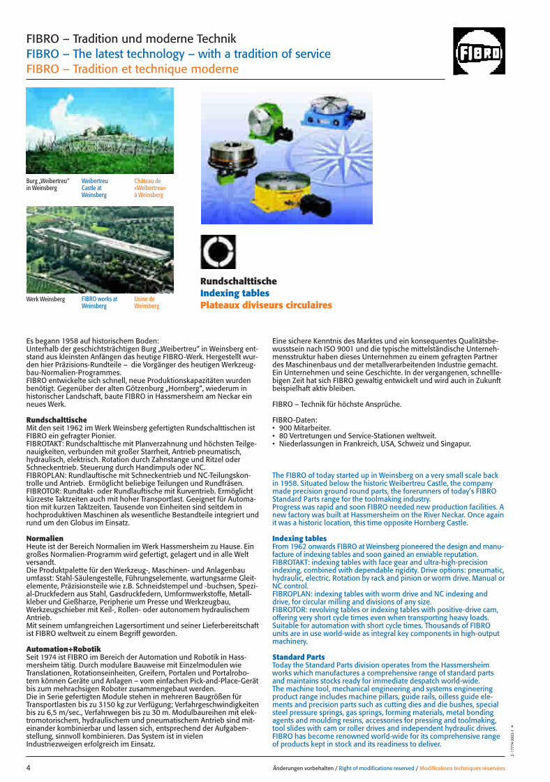
Es begann 1958 auf historischem Boden: Unterhalb der geschichtsträchtigen Burg „Weibertreu“ in Weinsberg ent-stand aus kleinsten Anfängen das heutige FIBRO-Werk. Hergestellt wur-den hier Präzisions-Rundteile – die Vorgänger des heutigen Werkzeug-bau-Normalien-Programmes. FIBRO entwickelte sich schnell, neue Produktionskapazitäten wurdenbenötigt. Gegenüber der alten Götzenburg „Hornberg“, wiederum inhistorischer Landschaft, baute FIBRO in Hassmersheim am Neckar einneues Werk.
Rundschalttische Mit den seit 1962 im Werk Weinsberg gefertigten Rundschalttischen istFIBRO ein gefragter Pionier.FIBROTAKT: Rundschalttische mit Planverzahnung und höchsten Teilge-nauigkeiten, verbunden mit großer Starrheit, Antrieb pneumatisch,hydraulisch, elektrisch. Rotation durch Zahnstange und Ritzel oderSchneckentrieb. Steuerung durch Handimpuls oder NC.FIBROPLAN: Rundlauftische mit Schneckentrieb und NC-Teilungskon-trolle und Antrieb. Ermöglicht beliebige Teilungen und Rundfräsen.FIBROTOR: Rundtakt- oder Rundlauftische mit Kurventrieb. Ermöglichtkürzeste Taktzeiten auch mit hoher Transportlast. Geeignet für Automa-tion mit kurzen Taktzeiten. Tausende von Einheiten sind seitdem inhochproduktiven Maschinen als wesentliche Bestandteile integriert undrund um den Globus im Einsatz.
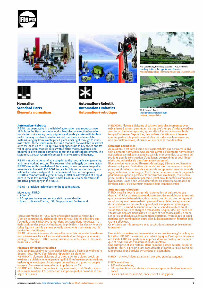
NormalienHeute ist der Bereich Normalien im Werk Hassmersheim zu Hause. Eingroßes Normalien-Programm wird gefertigt, gelagert und in alle Weltversandt. Die Produktpalette für den Werkzeug-, Maschinen- und Anlagenbauumfasst: Stahl-Säulengestelle, Führungselemente, wartungsarme Gleit-elemente, Präzisionsteile wie z.B. Schneidstempel und -buchsen, Spezi-al-Druckfedern aus Stahl, Gasdruckfedern, Umformwerkstoffe, Metall-kleber und Gießharze, Peripherie um Presse und Werkzeugbau,Werkzeugschieber mit Keil-, Rollen- oder autonomem hydraulischemAntrieb.Mit seinem umfangreichen Lagersortiment und seiner Lieferbereitschaftist FIBRO weltweit zu einem Begriff geworden.
Automation+Robotik Seit 1974 ist FIBRO im Bereich der Automation und Robotik in Hass-mersheim tätig. Durch modulare Bauweise mit Einzelmodulen wieTranslationen, Rotationseinheiten, Greifern, Portalen und Portalrobo-tern können Geräte und Anlagen – vom einfachen Pick-and-Place-Gerätbis zum mehrachsigen Roboter zusammengebaut werden. Die in Serie gefertigten Module stehen in mehreren Baugrößen fürTransportlasten bis zu 3150 kg zur Verfügung; Verfahrgeschwindigkeitenbis zu 6,5 m/sec., Verfahrwegen bis zu 30 m. Modulbaureihen mit elek-tromotorischem, hydraulischem und pneumatischem Antrieb sind mit-einander kombinierbar und lassen sich, entsprechend der Aufgaben-stellung, sinnvoll kombinieren. Das System ist in vielenIndustriezweigen erfolgreich im Einsatz.
Eine sichere Kenntnis des Marktes und ein konsequentes Qualitätsbe-wusstsein nach ISO 9001 und die typische mittelständische Unterneh-mensstruktur haben dieses Unternehmen zu einem gefragten Partnerdes Maschinenbaus und der metallverarbeitenden Industrie gemacht. Ein Unternehmen und seine Geschichte. In der vergangenen, schnellle-bigen Zeit hat sich FIBRO gewaltig entwickelt und wird auch in Zukunftbeispielhaft aktiv bleiben.
FIBRO – Technik für höchste Ansprüche.
FIBRO-Daten:• 900 Mitarbeiter.• 80 Vertretungen und Service-Stationen weltweit.• Niederlassungen in Frankreich, USA, Schweiz und Singapur.
The FIBRO of today started up in Weinsberg on a very small scale backin 1958. Situated below the historic Weibertreu Castle, the companymade precision ground round parts, the forerunners of today’s FIBROStandard Parts range for the toolmaking industry.Progress was rapid and soon FIBRO needed new production facilities. Anew factory was built at Hassmersheim on the River Neckar. Once againit was a historic location, this time opposite Hornberg Castle.
Indexing tablesFrom 1962 onwards FIBRO at Weinsberg pioneered the design and manu-facture of indexing tables and soon gained an enviable reputation.FIBROTAKT: indexing tables with face gear and ultra-high-precisionindexing, combined with dependable rigidity. Drive options: pneumatic,hydraulic, electric. Rotation by rack and pinion or worm drive. Manual orNC control.FIBROPLAN: indexing tables with worm drive and NC indexing anddrive, for circular milling and divisions of any size.FIBROTOR: revolving tables or indexing tables with positive-drive cam,offering very short cycle times even when transporting heavy loads.Suitable for automation with short cycle times. Thousands of FIBROunits are in use world-wide as integral key components in high-outputmachinery.
Standard PartsToday the Standard Parts division operates from the Hassmersheimworks which manufactures a comprehensive range of standard partsand maintains stocks ready for immediate despatch world-wide.The machine tool, mechanical engineering and systems engineeringproduct range includes machine pillars, guide rails, oilless guide ele-ments and precision parts such as cutting dies and die bushes, specialsteel pressure springs, gas springs, forming materials, metal bondingagents and moulding resins, accessories for pressing and toolmaking,tool slides with cam or roller drives and independent hydraulic drives.FIBRO has become renowned world-wide for its comprehensive rangeof products kept in stock and its readiness to deliver.
D_E_F_3farbig 26.08.2004 13:36 Uhr Seite 2
Alte Götzenburg „Hornberg“ gegenüber HassmersheimHornberg castle on the opposite side of the river.Ancien château fort de «Hornberg» faisant face à Hassmersheim
Werk HassmersheimThe FIBRO Hassmersheim plantUsine de Hassmersheim
Änderungen vorbehalten / Right of modifications reserved / Modifications techniques réservées 5
2·1
7775
·200
2·1
°
NormalienStandard PartsÉléments normalisés
Automation+RobotikAutomation+RoboticsAutomation+robotique
Automation+RoboticsFIBRO has been active in the field of automation and robotics since1974 from the Hassmersheim works. Modular construction based ontranslation units, rotary units, grippers and guide gantries with trolleysmake for easy construction of individual machines and completesystems, ranging from simple pick & place units right through to multi-axis robots. These series-manufactured modules are available in severalsizes for loads up to 3150 kg, traversing speeds up to 6.5 m/sec and tra-vel of up to 30 m. Module series with electric-motor, hydraulic andpneumatic drive can be combined to suit the specific requirements. Thesystem has a track record of success in many sectors of industry.
FIBRO is much in demand as a supplier to the mechanical engineeringand metalworking sectors. This success is based largely on three factors:FIBRO’s in-depth knowledge of the market, its commitment to qualityassurance in line with ISO 9001 and its flexible and responsive organi-sational structure so typical of medium-sized German companies.FIBRO: a company with a great history. FIBRO has developed at a rapidpace in these fast-moving times and will continue to demonstrate itsproactive philosophy in the future.
FIBRO – precision technology for the toughest tasks.
More about FIBRO:• 900 staff• 80 representatives and service stations world-wide• branch offices in France, USA, Singapore and Switzerland.
Tout a commencé en 1958, dans une région au passé historique :C’est en contrebas du château de «Weibertreu» chargé d’histoire quel’actuelle usine FIBRO a vu le jour dans des conditions modestes. Il yétait fabriqué des pièces cylindriques de précision – les devancières decelles figurant dans la gamme actuelle d’éléments normalisés pour lafabrication d’outillages.FIBRO prit un rapide essor, de nouvelles capacités de production devin-rent nécessaires. Face à l’ancien château de «Hornberg» – là aussi unpaysage historique – FIBRO construisit une nouvelle usine à Hassmers-heim sur le Neckar.
Plateaux diviseurs circulairesAvec ses plateaux diviseurs circulaires fabriqués à l’usine de Weinsbergdepuis 1962, FIBRO s’est fait une réputation de pionnier.FIBROTAKT : plateaux diviseurs circulaires à denture plane, précisionextrême de division, et une grande rigidité. Entraînement pneumatique,hydraulique, électrique. Rotation par crémaillère et pignon ou coupleroue/vis. Commande manuelle par impulsions ou CN.FIBROPLAN : Tables tournantes à couple roue/vis, contrôle de divisionet entraînement par CN, permettant n’importe quelles divisions et frai-sages circulaires.
FIBROTOR : Plateaux diviseurs circulaires ou tables tournantes avecmécanisme à cames, permettant de très brefs temps d’indexage mêmeavec forte charge transportée, appropriés à l’automation avec brefstemps d’indexage. Depuis lors, des milliers d’unités sont intégréescomme parties intégrantes essentielles dans des machines assurantune production élevée, et mis en œuvre dans le monde entier.
Éléments normalisésAujourd’hui, c’est dans l’usine de Hassmersheim que se trouve la divi-sion Éléments normalisés. Une grande gamme d’éléments normalisés yest fabriquée, stockée et expédiée dans le monde entier. La gamme deproduits pour la construction d’outillages, de machines et pour l’ingé-nierie des industries de transformation comprend :Blocs à colonnes en acier, éléments de guidage, éléments coulissant nedemandant guère d’entretien, pièces de précision comme par exemplepoinçons et matrices, ressorts spéciaux de compression en acier, ressortsà gaz, matériaux de formage, colles à métaux et résines à couler, appareilspériphériques pour la presse et la construction d’outillage, coulisseauxporte-outils à entraînement par came, galet ou autonome à commandehydraulique. Grâce à son vaste assortiment en stock et à sa capacité delivraison, FIBRO est devenu un symbole dans le monde entier.
Automation+robotiqueFIBRO travaille pour le secteur de l’automation et de la robotiquedepuis 1974. La construction modulaire avec des modules unitaires telsque des unités de translation, de rotation, des pinces, des portiques etrobot portique a Hassmersheim permet d’assembler des appareils etdes installations – du simple appareil pick and place au robot à plu-sieurs axes. Les modules fabriqués en série sont disponibles en plu-sieurs tailles pour des charges à transporter jusqu’à 3150 kg ; avec desvitesses de déplacement jusqu’à 6,5 m/s et des courses jusqu’à 30 m.Les séries de modules à entraînement électrique, hydraulique et pneu-matique sont combinables entre elles judicieusement en fonction de latâche à effectuer.Ce système est mis en œuvre avec succès dans beaucoup de secteursindustriels.
Une solide connaissance du marché et une conscience aigüe de la qua-lité selon ISO 9001, ainsi que la structure typique d’entreprise moyenneont fait de FIBRO un partenaire apprécié dans la construction mécani-que et l’industrie de transformation des métaux.Une entreprise et son histoire. Dans l’époque passée caractérisé par larapidité, FIBRO a pris un essor considérable et continuera, à l’avenir defaire preuve d’une activité dynamique et exemplaire.
FIBRO – Une technique satisfaisant aux plus grandes exigences.
FIBRO en chiffres :• 900 collaborateurs,• 80 représentations et stations de service après vente dans le monde
entier, • Filiales en France, aux USA, en Suisse et à Singapour
D_E_F_3farbig 26.08.2004 13:36 Uhr Seite 3
Änderungen vorbehalten / Right of modifications reserved / Modifications techniques réservées6
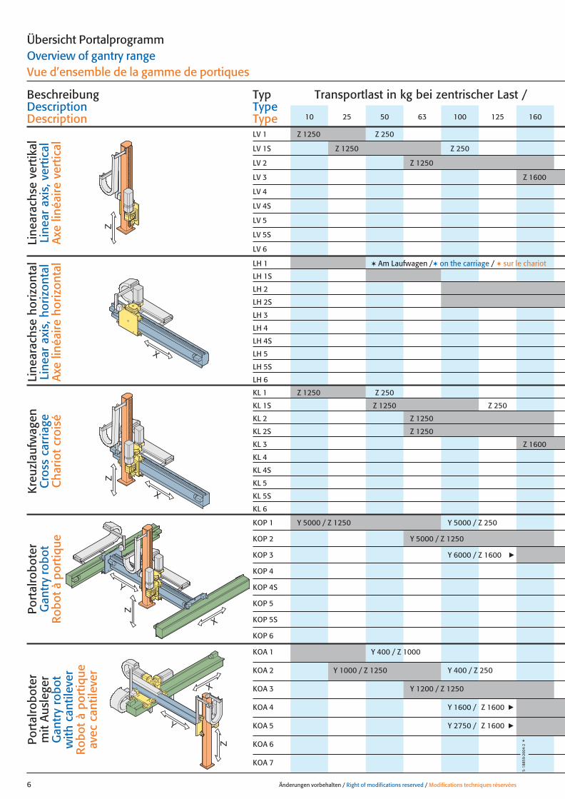
Übersicht PortalprogrammOverview of gantry rangeVue d’ensemble de la gamme de portiques
Transportlast in kg bei zentrischer Last / BeschreibungDescriptionDescription
TypTypeType
Z
Line
arac
hse
vert
ikal
Line
ar a
xis,
ver
tical
A
xe li
néai
re v
ertic
al
Line
arac
hse
horiz
onta
lLi
near
axi
s, h
oriz
onta
lA
xe li
néai
re h
oriz
onta
l
Kre
uzla
ufw
agen
Cro
ss c
arria
geC
hario
t cr
oisé
Port
alro
bote
rG
antr
y ro
bot
Rob
ot à
por
tique
Port
alro
bote
r m
it A
usle
ger
Gan
try
robo
t w
ith c
antil
ever
Rob
ot à
por
tique
av
ec c
antil
ever
X
Z
X
Z
X
Y
X
Y
Z
LV 1S Z 1250 Z 250
LV 2 Z 1250
LV 3 Z 1600
LV 4
LV 4S
LV 5
LV 5S
LV 6
LH 1 ✶ Am Laufwagen /✶ on the carriage / ✶ sur le chariot
LH 1S
LH 2
LH 2S
LH 3
LH 4
LH 4S
LH 5
LH 5S
LH 6
KOA 1 Y 400 / Z 1000
KOA 2 Y 1000 / Z 1250 Y 400 / Z 250
KOA 3 Y 1200 / Z 1250
KOA 4 Y 1600 / Z 1600 R
KOA 5 Y 2750 / Z 1600 R
KOA 6
KOA 7
LV 1 Z 1250 Z 250
KOP 2 Y 5000 / Z 1250
KOP 3 Y 6000 / Z 1600 R
KOP 4
KOP 4S
KOP 5
KOP 5S
KOP 6
KOP 1 Y 5000 / Z 1250 Y 5000 / Z 250
KL 2 Z 1250
KL 2S Z 1250
KL 3 Z 1600
KL 4
KL 4S
KL 5
KL 5S
KL 6
KL 1 Z 1250 Z 250
KL 1S Z 1250 Z 250
10 25 50 63 100 125 160
5·18
859·
2004
·2°
006_07 06.09.2004 11:59 Uhr Seite 2
Änderungen vorbehalten / Right of modifications reserved / Modifications techniques réservées 7
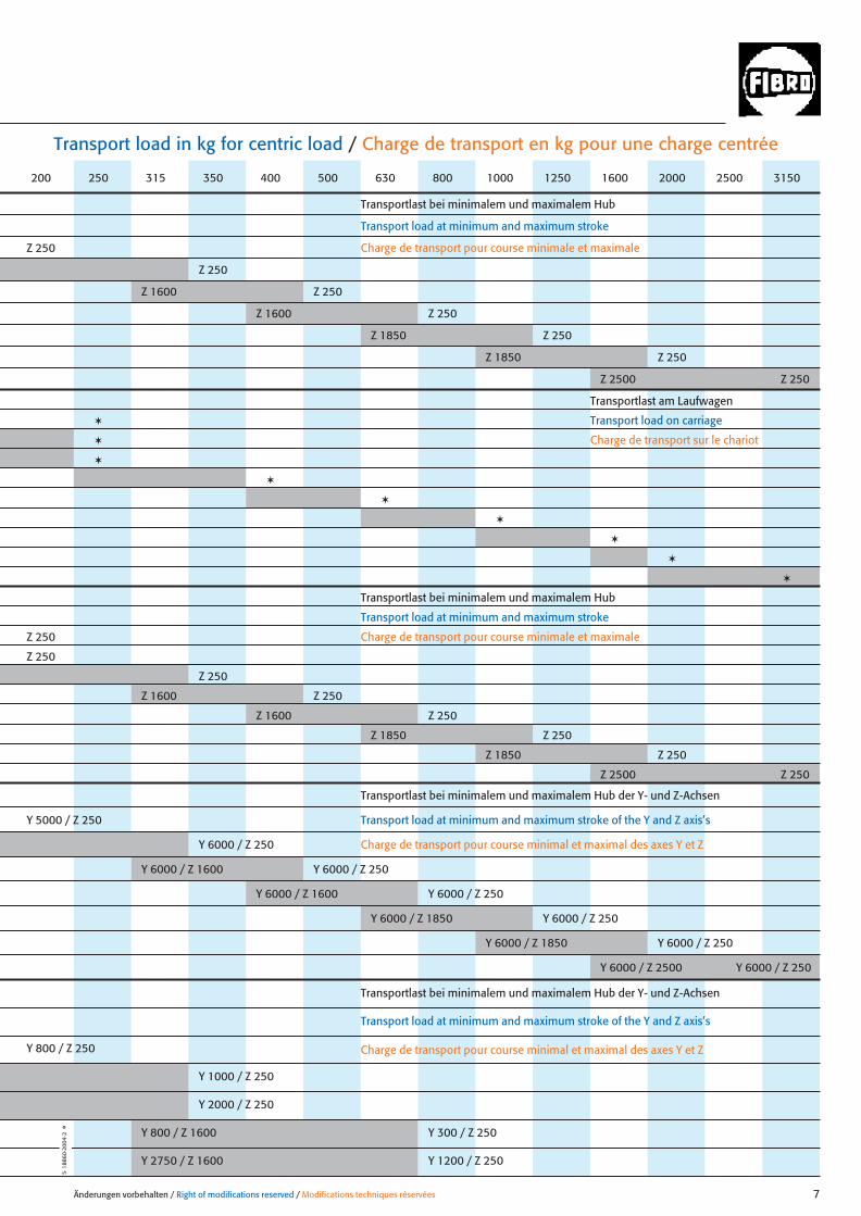
Transport load in kg for centric load / Charge de transport en kg pour une charge centrée
Transportlast bei minimalem und maximalem Hub
Transport load at minimum and maximum stroke
Transport load on carriage
Charge de transport pour course minimale et maximale
Charge de transport sur le chariot
Transportlast bei minimalem und maximalem Hub
Transport load at minimum and maximum stroke
Charge de transport pour course minimale et maximale
Transportlast bei minimalem und maximalem Hub der Y- und Z-Achsen
Transport load at minimum and maximum stroke of the Y and Z axis’s
Charge de transport pour course minimal et maximal des axes Y et Z
Transportlast bei minimalem und maximalem Hub der Y- und Z-Achsen
Transport load at minimum and maximum stroke of the Y and Z axis’s
Charge de transport pour course minimal et maximal des axes Y et Z
Z 250
Z 250
Z 1600 Z 250
Z 1600 Z 250
Z 1850 Z 250
Z 1850 Z 250
Z 2500 Z 250
✶
✶
✶
✶
✶
✶
✶
✶
✶
Y 800 / Z 250
Y 1000 / Z 250
Y 2000 / Z 250
Y 800 / Z 1600 Y 300 / Z 250
Y 2750 / Z 1600 Y 1200 / Z 250
Y 5000 / Z 250
Y 6000 / Z 250
Y 6000 / Z 1600 Y 6000 / Z 250
Y 6000 / Z 1600 Y 6000 / Z 250
Y 6000 / Z 1850 Y 6000 / Z 250
Y 6000 / Z 1850 Y 6000 / Z 250
Y 6000 / Z 2500 Y 6000 / Z 250
Z 250
Z 250
Z 250
Z 1600 Z 250
Z 1600 Z 250
Z 1850 Z 250
Z 1850 Z 250
Z 2500 Z 250
200 250 315 350 400 500 630 800 1000 1250 1600 2000 2500 3150
5·18
860·
2004
·2°
Transportlast am Laufwagen
006_07 06.09.2004 11:59 Uhr Seite 3
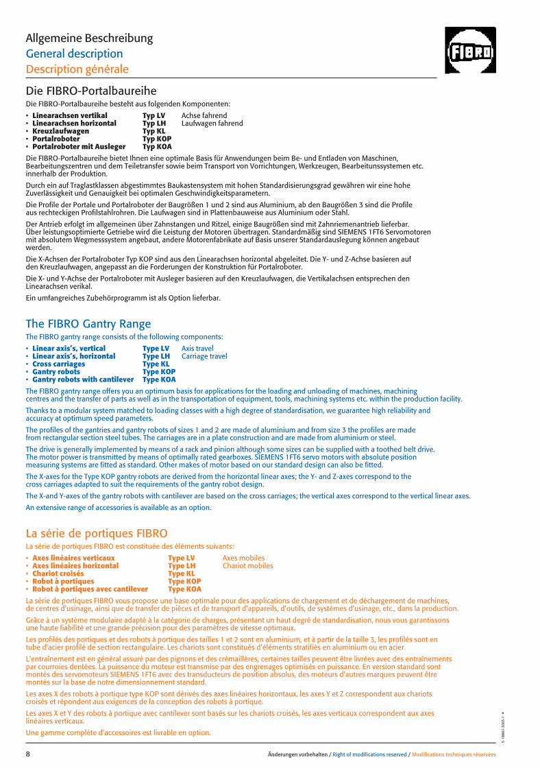
Die FIBRO-PortalbaureiheDie FIBRO-Portalbaureihe besteht aus folgenden Komponenten:
• Linearachsen vertikal Typ LV Achse fahrend• Linearachsen horizontal Typ LH Laufwagen fahrend• Kreuzlaufwagen Typ KL• Portalroboter Typ KOP• Portalroboter mit Ausleger Typ KOA
Die FIBRO-Portalbaureihe bietet Ihnen eine optimale Basis für Anwendungen beim Be- und Entladen von Maschinen, Bearbeitungszentren und dem Teiletransfer sowie beim Transport von Vorrichtungen, Werkzeugen, Bearbeitunssystemen etc. innerhalb der Produktion.
Durch ein auf Traglastklassen abgestimmtes Baukastensystem mit hohen Standardisierungsgrad gewähren wir eine hohe Zuverlässigkeit und Genauigkeit bei optimalen Geschwindigkeitsparametern.
Die Profile der Portale und Portalroboter der Baugrößen 1 und 2 sind aus Aluminium, ab den Baugrößen 3 sind die Profile aus rechteckigen Profilstahlrohren. Die Laufwagen sind in Plattenbauweise aus Aluminium oder Stahl.
Der Antrieb erfolgt im allgemeinen über Zahnstangen und Ritzel, einige Baugrößen sind mit Zahnriemenantrieb lieferbar.Über leistungsoptimierte Getriebe wird die Leistung der Motoren übertragen. Standardmäßig sind SIEMENS 1FT6 Servomotoren mit absolutem Wegmesssystem angebaut, andere Motorenfabrikate auf Basis unserer Standardauslegung können angebaut werden.
Die X-Achsen der Portalroboter Typ KOP sind aus den Linearachsen horizontal abgeleitet. Die Y- und Z-Achse basieren auf den Kreuzlaufwagen, angepasst an die Forderungen der Konstruktion für Portalroboter.
Die X- und Y-Achse der Portalroboter mit Ausleger basieren auf den Kreuzlaufwagen, die Vertikalachsen entsprechen denLinearachsen verikal.
Ein umfangreiches Zubehörprogramm ist als Option lieferbar.
The FIBRO Gantry RangeThe FIBRO gantry range consists of the following components:
• Linear axis’s, vertical Type LV Axis travel• Linear axis’s, horizontal Type LH Carriage travel• Cross carriages Type KL• Gantry robots Type KOP• Gantry robots with cantilever Type KOA
The FIBRO gantry range offers you an optimum basis for applications for the loading and unloading of machines, machining centres and the transfer of parts as well as in the transportation of equipment, tools, machining systems etc. within the production facility.
Thanks to a modular system matched to loading classes with a high degree of standardisation, we guarantee high reliability and accuracy at optimum speed parameters.
The profiles of the gantries and gantry robots of sizes 1 and 2 are made of aluminium and from size 3 the profiles are made from rectangular section steel tubes. The carriages are in a plate construction and are made from aluminium or steel.
The drive is generally implemented by means of a rack and pinion although some sizes can be supplied with a toothed belt drive. The motor power is transmitted by means of optimally rated gearboxes. SIEMENS 1FT6 servo motors with absolute position measuring systems are fitted as standard. Other makes of motor based on our standard design can also be fitted.
The X-axes for the Type KOP gantry robots are derived from the horizontal linear axes; the Y- and Z-axes correspond to the cross carriages adapted to suit the requirements of the gantry robot design.
The X-and Y-axes of the gantry robots with cantilever are based on the cross carriages; the vertical axes correspond to the vertical linear axes.
An extensive range of accessories is available as an option.
La série de portiques FIBROLa série de portiques FIBRO est constituée des éléments suivants:
• Axes linéaires verticaux Type LV Axes mobiles• Axes linéaires horizontal Type LH Chariot mobiles• Chariot croisés Type KL• Robot à portiques Type KOP• Robot à portiques avec cantilever Type KOA
La série de portiques FIBRO vous propose une base optimale pour des applications de chargement et de déchargement de machines, de centres d’usinage, ainsi que de transfer de pièces et de transport d’appareils, d’outils, de systèmes d’usinage, etc., dans la production.
Grâce à un système modulaire adapté à la catégorie de charges, présentant un haut degré de standardisation, nous vous garantissons une haute fiabilité et une grande précision pour des paramètres de vitesse optimaux.
Les profilés des portiques et des robots à portique des tailles 1 et 2 sont en aluminium, et à partir de la taille 3, les profilés sont en tube d’acier profilé de section rectangulaire. Les chariots sont constitués d’éléments stratifiés en aluminium ou en acier.
L’entraînement est en général assuré par des pignons et des crémaillères, certaines tailles peuvent être livrées avec des entraînements par courroies dentées. La puissance du moteur est transmise par des engrenages optimisés en puissance. En version standard sont montés des servomoteurs SIEMENS 1FT6 avec des transducteurs de position absolus, des moteurs d’autres marques peuvent être montés sur la base de notre dimensionnement standard.
Les axes X des robots à portique type KOP sont dérivés des axes linéaires horizontaux, les axes Y et Z correspondent aux chariots croisés et répondent aux exigences de la conception des robots à portique.
Les axes X et Y des robots à portique avec cantilever sont basés sur les chariots croisés, les axes verticaux correspondent aux axes linéaires verticaux.
Une gamme complète d’accessoires est livrable en option.
Änderungen vorbehalten / Right of modifications reserved / Modifications techniques réservées8
5·18
861·
2003
·1°
Allgemeine BeschreibungGeneral descriptionDescription générale
008 26.08.2004 13:38 Uhr Seite 2

Z
Änderungen vorbehalten / Right of modifications reserved / Modifications techniques réservées 9
5·18
862
·200
3·1
°Allgemeine Beschreibung – Linearachse, vertikal, TypGeneral description – Linear axis, vertical, TypeDescription générale – Axes linéaires verticaux Type LV
EnergieführungsketteEnergy supply chainChaîne de transmissiond’énergie
Endanschlag / HubbegrenzungEndstop / Stroke limiterButée fin de course / Limiteur de course
Antrieb – Zahnstange / RitzelDrive – rack / pinionEntraînement – crémaillère / pignon
BefestigungsflanschMounting flangeFlasque de fixation
VertikalachseVertical axisAxe vertical
FührungsleistenGuide waysBarres de guidage
BefestigungsplatteMounting platePlaque de fixation
RollenführungRoller guideGuidage à galets
009 26.08.2004 13:38 Uhr Seite 1
Änderungen vorbehalten / Right of modifications reserved / Modifications techniques réservées10
5·18
863·
2004
·2°
X
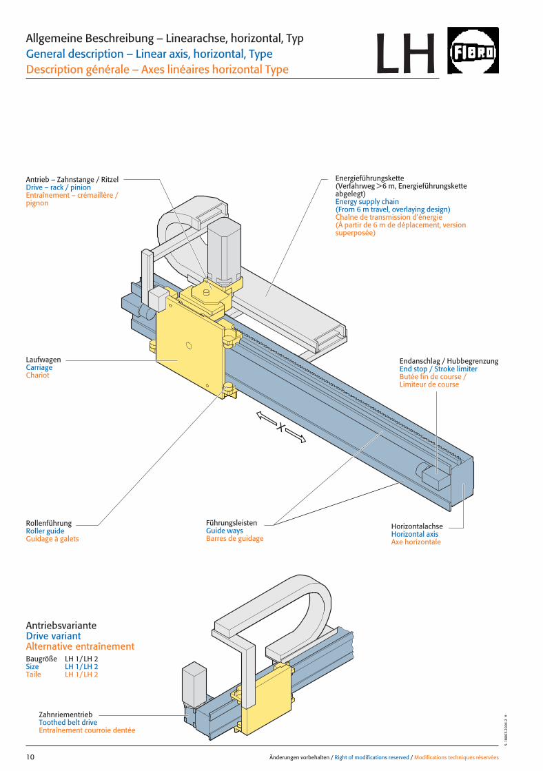
Allgemeine Beschreibung – Linearachse, horizontal, TypGeneral description – Linear axis, horizontal, TypeDescription générale – Axes linéaires horizontal Type
Energieführungskette(Verfahrweg >6 m, Energieführungskette abgelegt)Energy supply chain(From 6 m travel, overlaying design)Chaîne de transmission d’énergie (Á partir de 6 m de déplacement, version superposée)
LaufwagenCarriageChariot
Endanschlag / HubbegrenzungEnd stop / Stroke limiterButée fin de course / Limiteur de course
FührungsleistenGuide waysBarres de guidage
RollenführungRoller guideGuidage à galets
LH
Antrieb – Zahnstange / RitzelDrive – rack / pinionEntraînement – crémaillère / pignon
HorizontalachseHorizontal axisAxe horizontale
ZahnriementriebToothed belt driveEntraînement courroie dentée
AntriebsvarianteDrive variantAlternative entraînement Baugröße LH 1/LH 2Size LH 1/LH 2Taile LH 1/LH 2
010 26.08.2004 13:38 Uhr Seite 2

Z
X
Änderungen vorbehalten / Right of modifications reserved / Modifications techniques réservées 11
5·18
864
·200
4·2
°Allgemeine Beschreibung – Kreuzlaufwagen, TypGeneral description – Cross carriage, TypeDescription générale – Chariot croisé Type
Energieführungskette vertikalEnergy supply chain, verticalChaîne de transmission d’énergie verticale
BefestigungsflanschMounting flangeFlasque de fixation
Vertikalachse, (Z)Vertical axis, (Z)Axe vertical, (Z)
Energieführungskette, horizontal, (X)(Verfahrweg >6 m Energieführungskette abgelegt)Energy supply chain, horizontal, (X) (From 6 m travel, overlaying design)Chaîne de transmission d’énergie horizontale, (X) (Á partir de 6 m de déplacement, version superposée)
Antrieb, vertikal – Zahnstange / RitzelDrive, vertical – rack / pinionEntraînement vertical – crémaillère / pignon
Antrieb, horizontal – Zahnstange / RitzelDrive, horizontal – rack / pinionEntraînement horizontal – crémaillère / pignon
ZahnriementriebToothed belt driveEntraînement courroie dentée
Endanschlag / HubbegrenzungEnd stop / Stroke limiterButée fin de course / Limiteur de course
Horizontalachse, (X)Horizontal axis, (X)Axe horizontale, (X)
FührungsleistenGuide waysBarres de guidage
FührungsleistenGuide waysBarres de guidage
RollenführungRoller guideGuidage à galets
LaufwagenCarriageChariot
Endanschlag / HubbegrenzungEnd stop / Stroke limiterButée fin de course / Limiteur de course
KL
Antriebsvariante, horizontalDrive variant, horizontalAlternative entraînement horizontalBaugröße KL 1/KL 2Size KL 1/KL 2Taile KL 1/KL 2
011 26.08.2004 13:38 Uhr Seite 1
Änderungen vorbehalten / Right of modifications reserved / Modifications techniques réservées12
5·18
865·
2004
·2°
Z
X
Y
Y
X
„A”
„A”
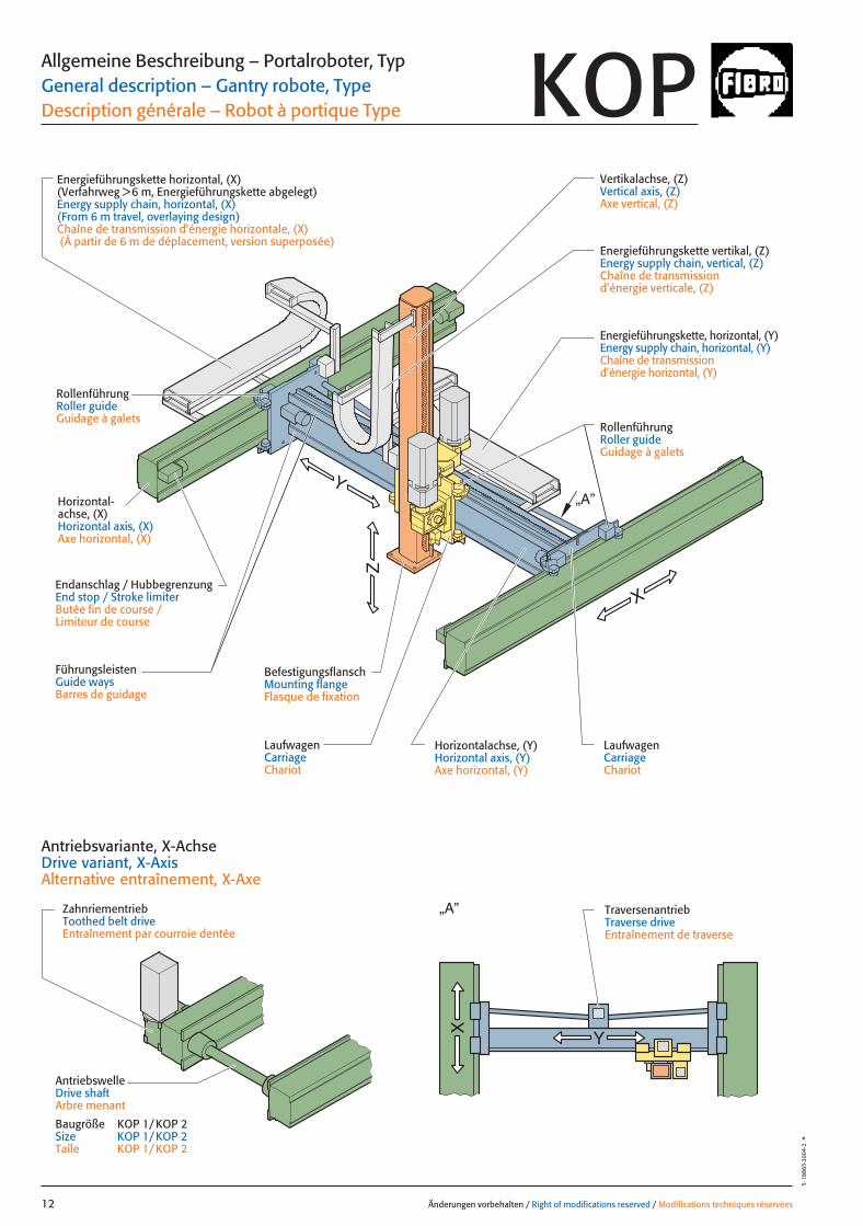
Allgemeine Beschreibung – Portalroboter, TypGeneral description – Gantry robote, TypeDescription générale – Robot à portique Type
LaufwagenCarriageChariot
LaufwagenCarriageChariot
Endanschlag / HubbegrenzungEnd stop / Stroke limiterButée fin de course / Limiteur de course
Horizontal-achse, (X)Horizontal axis, (X)Axe horizontal, (X)
FührungsleistenGuide waysBarres de guidage
RollenführungRoller guideGuidage à galets
Energieführungskette vertikal, (Z)Energy supply chain, vertical, (Z)Chaîne de transmission d’énergie verticale, (Z)
Energieführungskette, horizontal, (Y)Energy supply chain, horizontal, (Y)Chaîne de transmission d’énergie horizontal, (Y)
BefestigungsflanschMounting flangeFlasque de fixation
Vertikalachse, (Z)Vertical axis, (Z)Axe vertical, (Z)
TraversenantriebTraverse driveEntraînement de traverse
Energieführungskette horizontal, (X)(Verfahrweg >6 m, Energieführungskette abgelegt)Energy supply chain, horizontal, (X) (From 6 m travel, overlaying design)Chaîne de transmission d’énergie horizontale, (X)(Á partir de 6 m de déplacement, version superposée)
ZahnriementriebToothed belt driveEntraînement par courroie dentée
Antriebsvariante, X-AchseDrive variant, X-AxisAlternative entraînement, X-Axe
Horizontalachse, (Y)Horizontal axis, (Y)Axe horizontal, (Y)
AntriebswelleDrive shaftArbre menant
Baugröße KOP 1/KOP 2Size KOP 1/KOP 2Taile KOP 1/KOP 2
RollenführungRoller guideGuidage à galets
KOP
012 26.08.2004 13:38 Uhr Seite 2
Z
Y
X
Änderungen vorbehalten / Right of modifications reserved / Modifications techniques réservées 13
5·18
866
·200
4·2
°
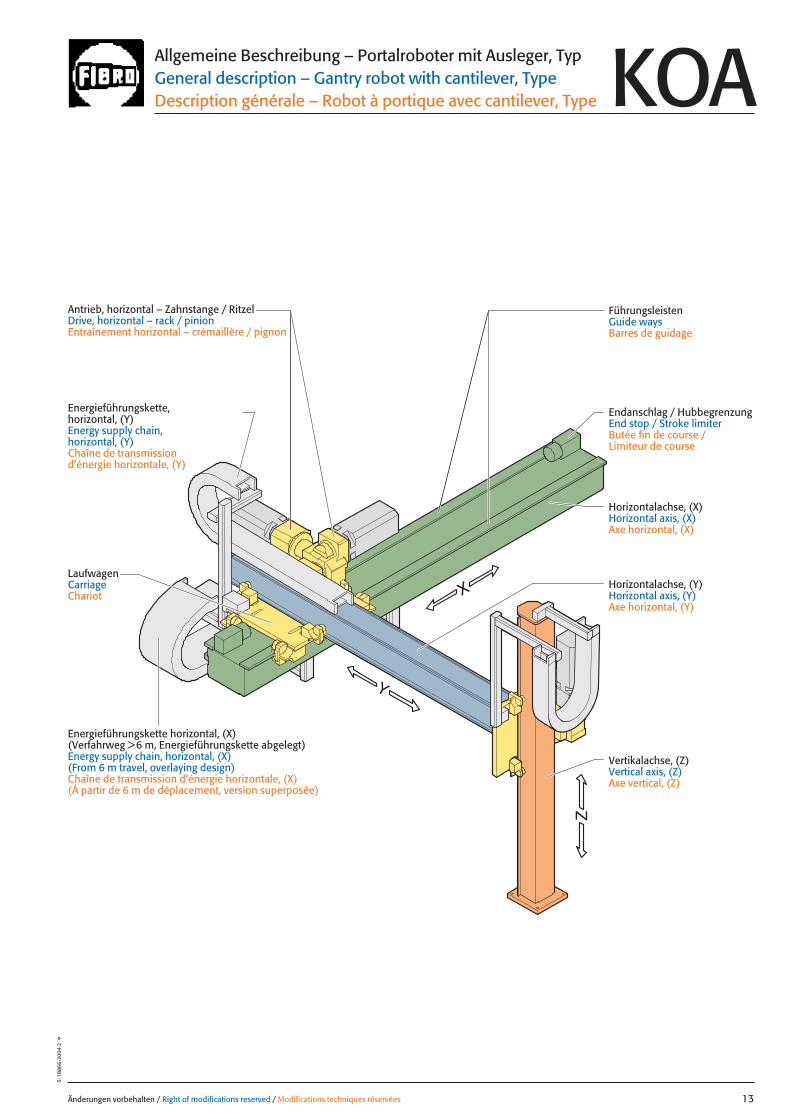
Energieführungskette, horizontal, (Y)Energy supply chain, horizontal, (Y) Chaîne de transmission d’énergie horizontale, (Y)
Antrieb, horizontal – Zahnstange / RitzelDrive, horizontal – rack / pinionEntraînement horizontal – crémaillère / pignon
LaufwagenCarriageChariot
FührungsleistenGuide waysBarres de guidage
Endanschlag / HubbegrenzungEnd stop / Stroke limiterButée fin de course / Limiteur de course
Vertikalachse, (Z)Vertical axis, (Z)Axe vertical, (Z)
Energieführungskette horizontal, (X)(Verfahrweg >6 m, Energieführungskette abgelegt)Energy supply chain, horizontal, (X) (From 6 m travel, overlaying design)Chaîne de transmission d’énergie horizontale, (X) (Á partir de 6 m de déplacement, version superposée)
Allgemeine Beschreibung – Portalroboter mit Ausleger, TypGeneral description – Gantry robot with cantilever, TypeDescription générale – Robot à portique avec cantilever, Type KOA
Horizontalachse, (X)Horizontal axis, (X)Axe horizontal, (X)
Horizontalachse, (Y)Horizontal axis, (Y)Axe horizontal, (Y)
013 26.08.2004 13:38 Uhr Seite 1
Änderungen vorbehalten / Right of modifications reserved / Modifications techniques réservées14
5·1
8867
·200
3·1
°
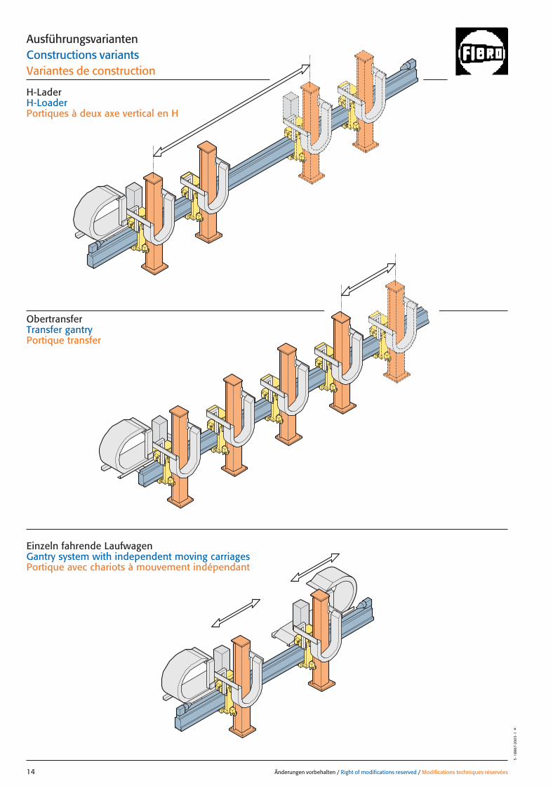
ObertransferTransfer gantryPortique transfer
Einzeln fahrende LaufwagenGantry system with independent moving carriagesPortique avec chariots à mouvement indépendant
AusführungsvariantenConstructions variantsVariantes de construction
H-LaderH-LoaderPortiques à deux axe vertical en H
014 26.08.2004 13:38 Uhr Seite 2
Änderungen vorbehalten / Right of modifications reserved / Modifications techniques réservées 15
5·18
868
·200
3·1
°
Linea
rach
se, v
ertik
al / L
inea
r axis
, ver
tical
Axes
linéa
ires v
ertic
aux
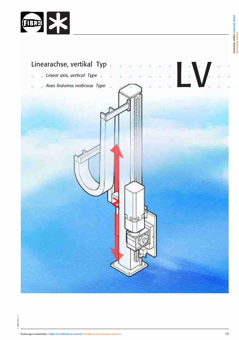
Linearachse, vertikal TypLinear axis, vertical Type
Axes linéaires verticaux Type LV
015 27.08.2004 5:25 Uhr Seite 1
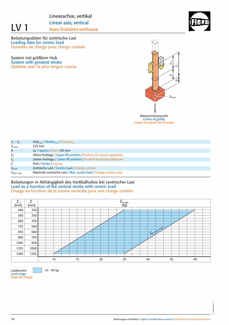
Belastungsdaten für zentrische LastLoading data for centric loadDonnées de charge pour charge centrée
System mit größtem HubSystem with greatest strokeSystème avec la plus longue course
MassenschwerpunktCentre of gravity
Centre de gravité de la masse
0Z
Z
2Z
A
G zentr max.
485
585
985
1085
1235
1485
250
350
450
500
600
1000
1250
Z
10
Z 2[mm] [mm]
750
850
685
735
835
10 - 40 kg
G zentr[kg]
15 20 25 30 35 40
Änderungen vorbehalten / Right of modifications reserved / Modifications techniques réservées16
5·19
XXX
·200
4·1
°
Linearachse, vertikalLinear axis, verticalAxes linéaires verticauxLV 1
Z2 – Z0 Hubmax. / Strokemax. / Coursemax.
Z0 min. 235 mmA ca. / approx. / env. 100 mmZ0 Obere Hublage / Upper lift position /Position de course supérieureZ2 Untere Hublage / Lower lift position / Position de course inférieureZ Hub / Stroke / CourseGzentr. Zentrische Last / Centric load / Charge centréeGzent. max. Maximale zentrische Last / Max. centric load / Charge centrée max.
Belastungen in Abhängigkeit des Vertikalhubes bei zentrischer Last Load as a function of the vertical stroke with centric loadCharge en fonction de la course verticale pour une charge centrée
LastbereichLoad range Plage de charge
Gzentr.
016 27.08.2004 5:26 Uhr Seite 2

= Gexzentr.y
Änderungen vorbehalten / Right of modifications reserved / Modifications techniques réservées 17
5·1
9XXX
·200
4·1
°
Belastungsdaten für exzentrische Lastbezogen auf Mitte Befestigungslochbild Z-Achse für x; y
Loading data for eccentric loadreferred to the centre of the fixing hole pattern Z-axis for x; y
Données de charge pour une charge excentréerapporté au centre du gabarit des trous de fixation axe Z pour x; y
G [kg], x [m], y [m]
= Gexzentr.x
Gzentr. � 0,135
(x + 0,135)
Gzentr. � 0,085
(y + 0,085)
Gzent. max. = Gzentr.
aus Diagrammfrom diagramvaleur relevée dans le diagramme
* Massenschwerpunkt* Centre of gravity* Centre de gravité de
la massex
Gy 2
Gy 1
Gx
2y
1y
0Z
Z
2Z
A
*
*
*
Linearachse, vertikalLinear axis, verticalAxes linéaires verticaux LV 1
Z0 Obere Hublage / Upper lift position / Position de course supérieureZ2 Untere Hublage / Lower lift position / Position de course inférieureZ Hub / Stroke / CourseA ca. / approx. / env. 100 mmGzentr. Zentrische Last / Centric load / Charge centréeGzent. max. Maximale zentrische Last / Max. centric load / Charge centrée max.Gexzent. max. Maximale exzentrische Last / Max. eccentric load / Charge excentrique max.
AntriebsdatenDrive data’sDonnées de l’entraînement
GeschwindigkeitSpeed [m/sec] 1 0,66 1,61 2Vitesse
Wiederholgenauigkeit der PositionierungRepeat accuracy for positioning [mm] +/– 0,1 +/– 0,1 +/– 0,1 +/– 0,1Fidélité de reproduction du positionnement
BeschleunigungAcceleration [m/sec2] 3 3 4 4Accélération
Servomotor Siemens 1FT 6 Siemens 1FT 6 Siemens 1FT 6 Siemens 1FT 6Servo motor Siemens 1FK 7 Siemens 1FK 7 Siemens 1FK 7 Siemens 1FK 7Servomoteur
UntersetzungStep-down ratio 10:1 15:1 10:1 7,5:1Taux de réduction
Linea
rach
se, v
ertik
al / L
inea
r axis
, ver
tical
Axes
linéa
ires v
ertic
aux
017 27.08.2004 5:26 Uhr Seite 1
LBZ Z2 Z[mm] [mm] [mm]
690 485 250 ●
790 585 350 ●
890 685 450 ●
940 735 500 ●
1040 835 600 ●
1190 935 750 ●
1290 1085 850 ●
1440 1235 1000 ●
1690 1485 1250 ●
Antriebsausführung / Drive design / Version d’entraînementvZ1 = 1 m/sec aZ1 = 3 m/sec2 ●
vZ2 = 0,66 m/sec aZ2 = 3 m/sec2 ●
vZ3 = 1,61 m/sec aZ3 = 4 m/sec2 ●
vZ4 = 2 m/sec aZ4 = 4 m/sec2 ●
mit Motorwith motor ●
avec moteurohne Motorwithout motor �
sans moteurAntriebsmotor Siemens 1FT 6 ●Drive motorMoteur d’entraînement Siemens 1FK 7 ●
andere Herstellerother manufacturers �
autres fabricants
AntriebDriveEntraînement
b2
48
54
b1
ZZ
0=
Z2
1616
LBZ
50*
91
AA* 30
0
235
Y
M10(4x)65
103
91
120
11
8,5
70
90
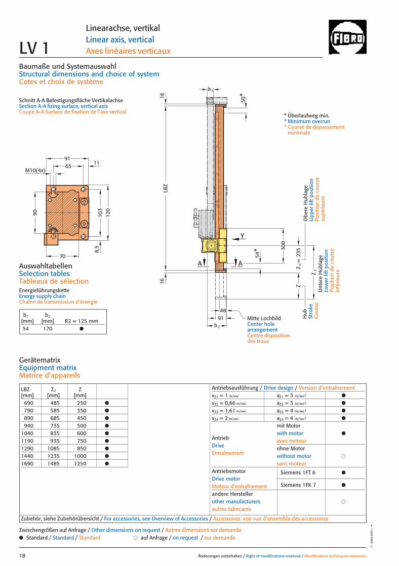
Baumaße und SystemauswahlStructural dimensions and choice of systemCotes et choix de système
Schnitt A-A Befestigungsfläche VertikalachseSection A-A fixing surface, vertical axisCoupe A-A Surface de fixation de l’axe vertical
AuswahltabellenSelection tablesTableaux de sélectionEnergieführungsketteEnergy supply chainChaîne de transmission d’énergie
Änderungen vorbehalten / Right of modifications reserved / Modifications techniques réservées18
5·1
9XXX
·200
4·1
°
Linearachse, vertikalLinear axis, verticalAxes linéaires verticauxLV 1
GerätematrixEquipment matrixMatrice d’appareils
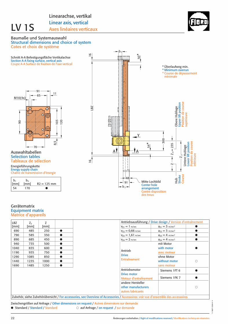
b1 b2[mm] [mm] R2 = 125 mm54 170 ●
Zubehör, siehe Zubehörübersicht / For accessories, see Overview of Accessories / Accessoires: voir vue d’ensemble des accessoires
● Standard / Standard / Standard � auf Anfrage / on request / sur demandeZwischengrößen auf Anfrage / Other dimensions on request / Autres dimensions sur demande
Hub
Stro
keC
ours
e
Obe
re H
ubla
geU
pper
lift
pos
ition
Posi
tion
de c
ours
esu
périe
ure
Unt
ere
Hub
lage
Low
er li
ft p
ositi
onPo
sitio
n de
cou
rse
infé
rieur
e
* Überlaufweg min.* Minimum overrun* Course de dépassement
minimale
Mitte LochbildCenter hole arrangementCentre dispositiondes trous
018 27.08.2004 5:26 Uhr Seite 2
M8(10x)
1811
7,5
117,
5
290
270
235
215185
60
107,5
215
R2
35
B - B
B B
27,6
Änderungen vorbehalten / Right of modifications reserved / Modifications techniques réservées 19
5·19
XXX·
2004
·1°
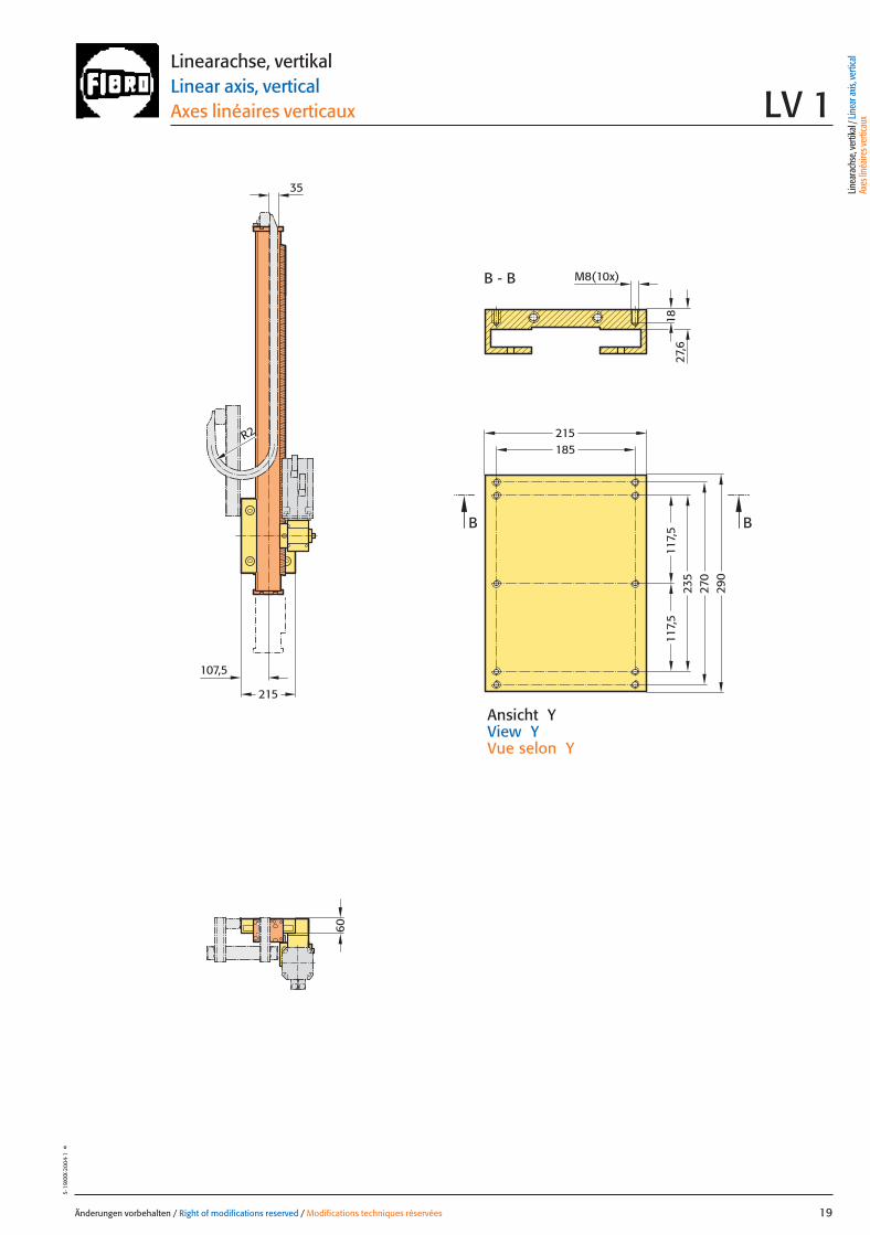
Ansicht YView YVue selon Y
Linearachse, vertikalLinear axis, verticalAxes linéaires verticaux LV 1
Linea
rach
se, v
ertik
al / L
inea
r axis
, ver
tical
Axes
linéa
ires v
ertic
aux
019 27.08.2004 5:25 Uhr Seite 1
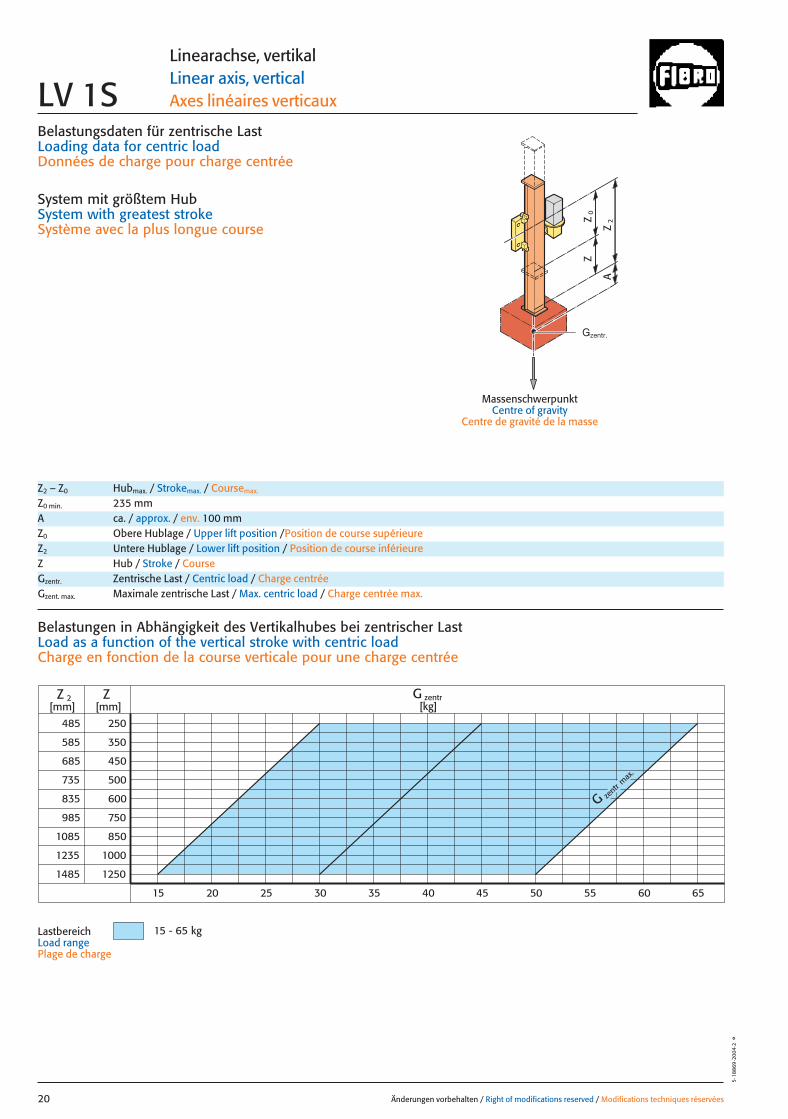
Belastungsdaten für zentrische LastLoading data for centric loadDonnées de charge pour charge centrée
System mit größtem HubSystem with greatest strokeSystème avec la plus longue course
MassenschwerpunktCentre of gravity
Centre de gravité de la masse
0Z
Z
2Z
A
G zent
r max
.
485
585
985
1085
1235
1485
250
350
450
500
600
1000
1250
ZZ 2[mm] [mm]
750
850
685
735
835
15 - 65 kg
G zentr[kg]
20 3015 25 35 40 45 50 55 60 65
Änderungen vorbehalten / Right of modifications reserved / Modifications techniques réservées20
5·18
869
·200
4·2
°
Linearachse, vertikalLinear axis, verticalAxes linéaires verticauxLV 1S
Z2 – Z0 Hubmax. / Strokemax. / Coursemax.
Z0 min. 235 mmA ca. / approx. / env. 100 mmZ0 Obere Hublage / Upper lift position /Position de course supérieureZ2 Untere Hublage / Lower lift position / Position de course inférieureZ Hub / Stroke / CourseGzentr. Zentrische Last / Centric load / Charge centréeGzent. max. Maximale zentrische Last / Max. centric load / Charge centrée max.
Belastungen in Abhängigkeit des Vertikalhubes bei zentrischer Last Load as a function of the vertical stroke with centric loadCharge en fonction de la course verticale pour une charge centrée
LastbereichLoad range Plage de charge
Gzentr.
020 27.08.2004 5:25 Uhr Seite 2

= Gexzentr.y
Änderungen vorbehalten / Right of modifications reserved / Modifications techniques réservées 21
5·1
8870
·200
4·2
°
Belastungsdaten für exzentrische Lastbezogen auf Mitte Befestigungslochbild Z-Achse für x; y
Loading data for eccentric loadreferred to the centre of the fixing hole pattern Z-axis for x; y
Données de charge pour une charge excentréerapporté au centre du gabarit des trous de fixation axe Z pour x; y
G [kg], x [m], y [m]
= Gexzentr.x
Gzentr. � 0,135
(x + 0,135)
Gzentr. � 0,085
(y + 0,085)
Gzent. max. = Gzentr.
aus Diagrammfrom diagramvaleur relevée dans le diagramme
* Massenschwerpunkt* Centre of gravity* Centre de gravité de
la massex
Gy 2
Gy 1
Gx
2y
1y
0Z
Z
2Z
A
*
*
*
Linearachse, vertikalLinear axis, verticalAxes linéaires verticaux LV 1S
Z0 Obere Hublage / Upper lift position / Position de course supérieureZ2 Untere Hublage / Lower lift position / Position de course inférieureZ Hub / Stroke / CourseA ca. / approx. / env. 100 mmGzentr. Zentrische Last / Centric load / Charge centréeGzent. max. Maximale zentrische Last / Max. centric load / Charge centrée max.Gexzent. max. Maximale exzentrische Last / Max. eccentric load / Charge excentrique max.
AntriebsdatenDrive data’sDonnées de l’entraînement
GeschwindigkeitSpeed [m/sec] 1 0,66 1,61 2Vitesse
Wiederholgenauigkeit der PositionierungRepeat accuracy for positioning [mm] +/– 0,1 +/– 0,1 +/– 0,1 +/– 0,1Fidélité de reproduction du positionnement
BeschleunigungAcceleration [m/sec2] 3 3 4 4Accélération
Servomotor Siemens 1FT 6 Siemens 1FT 6 Siemens 1FT 6 Siemens 1FT 6Servo motor Siemens 1FK 7 Siemens 1FK 7 Siemens 1FK 7 Siemens 1FK 7Servomoteur
UntersetzungStep-down ratio 15:1 25:1 10:1 7,5:1Taux de réduction
Linea
rach
se, v
ertik
al / L
inea
r axis
, ver
tical
Axes
linéa
ires v
ertic
aux
21 27.08.2004 5:29 Uhr Seite 1
48
Z
Z2
300
91b2
b1
LBZ
1616
50*
Z0=
235
A54
*
Y
A
M10(4x)65
103
91
120
11
8,5
70
90
Baumaße und SystemauswahlStructural dimensions and choice of systemCotes et choix de système
Schnitt A-A Befestigungsfläche VertikalachseSection A-A fixing surface, vertical axisCoupe A-A Surface de fixation de l’axe vertical
Änderungen vorbehalten / Right of modifications reserved / Modifications techniques réservées22
5·18
871·
2004
·4°
Linearachse, vertikalLinear axis, verticalAxes linéaires verticauxLV 1S
Hub
Stro
keC
ours
e
Obe
re H
ubla
geU
pper
lift
pos
ition
Posi
tion
de c
ours
esu
périe
ure
Unt
ere
Hub
lage
Low
er li
ft p
ositi
onPo
sitio
n de
cou
rse
infé
rieur
e
* Überlaufweg min.* Minimum overrun* Course de dépassement
minimale
Mitte LochbildCenter hole arrangementCentre dispositiondes trous
LBZ Z2 Z[mm] [mm] [mm]
690 485 250 ●
790 585 350 ●
890 685 450 ●
940 735 500 ●
1040 835 600 ●
1190 935 750 ●
1290 1085 850 ●
1440 1235 1000 ●
1690 1485 1250 ●
Antriebsausführung / Drive design / Version d’entraînementvZ1 = 1 m/sec aZ1 = 3 m/sec2 ●
vZ2 = 0,66 m/sec aZ2 = 3 m/sec2 ●
vZ3 = 1,61 m/sec aZ3 = 4 m/sec2 ●
vZ4 = 2 m/sec aZ4 = 4 m/sec2 ●
mit Motorwith motor ●
avec moteurohne Motorwithout motor �
sans moteurAntriebsmotor Siemens 1FT 6 ●Drive motorMoteur d’entraînement Siemens 1FK 7 ●
andere Herstellerother manufacturers �
autres fabricants
AntriebDriveEntraînement
AuswahltabellenSelection tablesTableaux de sélectionEnergieführungsketteEnergy supply chainChaîne de transmission d’énergie
GerätematrixEquipment matrixMatrice d’appareils
b1 b2[mm] [mm] R2 = 125 mm54 170 ●
Zubehör, siehe Zubehörübersicht / For accessories, see Overview of Accessories / Accessoires: voir vue d’ensemble des accessoires
● Standard / Standard / Standard � auf Anfrage / on request / sur demandeZwischengrößen auf Anfrage / Other dimensions on request / Autres dimensions sur demande
022 27.08.2004 5:29 Uhr Seite 2

60
215
35
R2
1811
7,5
117,
5
290
270
235
215185
B - B
B B
27,6
107,5
M8(10x)
Änderungen vorbehalten / Right of modifications reserved / Modifications techniques réservées 23
5·18
872·
2004
·2°
Ansicht YView YVue selon Y
Linearachse, vertikalLinear axis, verticalAxes linéaires verticaux LV 1S
Linea
rach
se, v
ertik
al / L
inea
r axis
, ver
tical
Axes
linéa
ires v
ertic
aux
023 27.08.2004 5:29 Uhr Seite 1
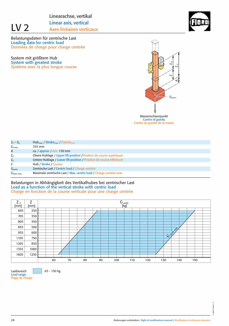
Belastungsdaten für zentrische LastLoading data for centric loadDonnées de charge pour charge centrée
System mit größtem HubSystem with greatest strokeSystème avec la plus longue course
MassenschwerpunktCentre of gravity
Centre de gravité de la masse
0Z
Z
2Z
A
G zent
r max
.
605
705
1105
1205
1355
1605
250
350
450
500
600
1000
1250
ZZ 2[mm] [mm]
70 80 90 150
750
850
805
855
955
60 140130120110100
G zentr[kg]
63 - 150 kg
Änderungen vorbehalten / Right of modifications reserved / Modifications techniques réservées24
5·18
873
·200
4·2
°
Linearachse, vertikalLinear axis, verticalAxes linéaires verticauxLV 2
Z2 – Z0 Hubmax. / Strokemax. / Coursemax.
Z0 min. 355 mmA ca. / approx. / env. 150 mmZ0 Obere Hublage / Upper lift position /Position de course supérieureZ2 Untere Hublage / Lower lift position / Position de course inférieureZ Hub / Stroke / CourseGzentr. Zentrische Last / Centric load / Charge centréeGzent. max. Maximale zentrische Last / Max. centric load / Charge centrée max.
Belastungen in Abhängigkeit des Vertikalhubes bei zentrischer LastLoad as a function of the vertical stroke with centric loadCharge en fonction de la course verticale pour une charge centrée
LastbereichLoad range Plage de charge
Gzentr.
024 27.08.2004 5:26 Uhr Seite 2
= Gexzentr.y
Änderungen vorbehalten / Right of modifications reserved / Modifications techniques réservées 25
5·1
8874
·200
3·1
°
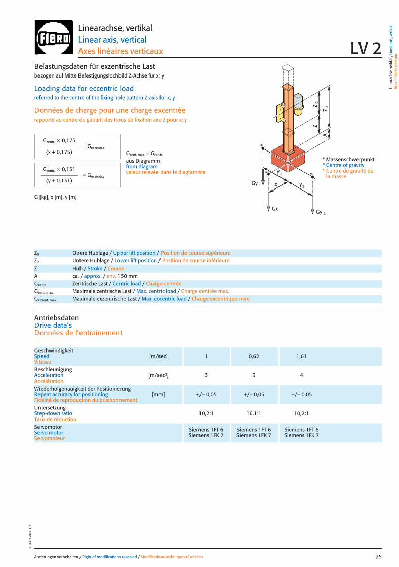
Belastungsdaten für exzentrische Lastbezogen auf Mitte Befestigungslochbild Z-Achse für x; y
Loading data for eccentric loadreferred to the centre of the fixing hole pattern Z-axis for x; y
Données de charge pour une charge excentréerapporté au centre du gabarit des trous de fixation axe Z pour x; y
G [kg], x [m], y [m]
= Gexzentr.x
Gzentr. � 0,175
(x + 0,175)
Gzentr. � 0,131
(y + 0,131)
Gzent. max. = Gzentr.
aus Diagrammfrom diagramvaleur relevée dans le diagramme
* Massenschwerpunkt* Centre of gravity* Centre de gravité de
la massex
Gy 2
Gy 1
Gx
2y
1y
0Z
Z
2Z
A
*
*
*
Linearachse, vertikalLinear axis, verticalAxes linéaires verticaux LV 2
Z0 Obere Hublage / Upper lift position / Position de course supérieureZ2 Untere Hublage / Lower lift position / Position de course inférieureZ Hub / Stroke / CourseA ca. / approx. / env. 150 mmGzentr. Zentrische Last / Centric load / Charge centréeGzent. max. Maximale zentrische Last / Max. centric load / Charge centrée max.Gexzent. max. Maximale exzentrische Last / Max. eccentric load / Charge excentrique max.
AntriebsdatenDrive data’sDonnées de l’entraînement
GeschwindigkeitSpeed [m/sec] 1 0,62 1,61Vitesse
Wiederholgenauigkeit der PositionierungRepeat accuracy for positioning [mm] +/– 0,05 +/– 0,05 +/– 0,05Fidélité de reproduction du positionnement
BeschleunigungAcceleration [m/sec2] 3 3 4Accélération
Servomotor Siemens 1FT 6 Siemens 1FT 6 Siemens 1FT 6Servo motor Siemens 1FK 7 Siemens 1FK 7 Siemens 1FK 7Servomoteur
UntersetzungStep-down ratio 10,2:1 16,1:1 10,2:1Taux de réduction
Linea
rach
se, v
ertik
al / L
inea
r axis
, ver
tical
Axes
linéa
ires v
ertic
aux
025 27.08.2004 5:26 Uhr Seite 1
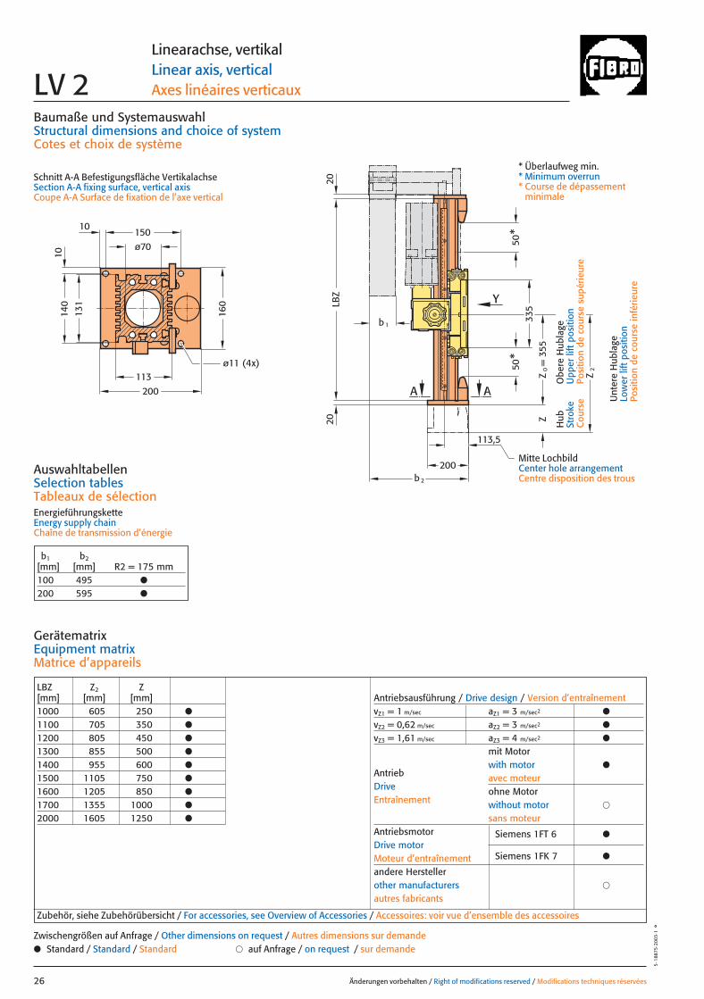
LBZ Z2 Z[mm] [mm] [mm]1000 605 250 ●
1100 705 350 ●
1200 805 450 ●
1300 855 500 ●
1400 955 600 ●
1500 1105 750 ●
1600 1205 850 ●
1700 1355 1000 ●
2000 1605 1250 ●
Antriebsausführung / Drive design / Version d’entraînementvZ1 = 1 m/sec aZ1 = 3 m/sec2 ●
vZ2 = 0,62 m/sec aZ2 = 3 m/sec2 ●
vZ3 = 1,61 m/sec aZ3 = 4 m/sec2 ●
mit Motorwith motor ●
avec moteurohne Motorwithout motor �
sans moteurAntriebsmotor Siemens 1FT 6 ●Drive motorMoteur d’entraînement Siemens 1FK 7 ●
andere Herstellerother manufacturers �
autres fabricants
AntriebDriveEntraînement
131
113
b2
200
A A
10
1014
0
ø70150
200
160
ø11 (4x)
LBZ
b 1
50*
50*
335
Z
Z2
= 3
55Z
0
113,5
Y
2020
Baumaße und SystemauswahlStructural dimensions and choice of systemCotes et choix de système
Schnitt A-A Befestigungsfläche VertikalachseSection A-A fixing surface, vertical axisCoupe A-A Surface de fixation de l’axe vertical
AuswahltabellenSelection tablesTableaux de sélectionEnergieführungsketteEnergy supply chainChaîne de transmission d’énergie
Änderungen vorbehalten / Right of modifications reserved / Modifications techniques réservées26
5·1
8875
·200
3·1
°
Linearachse, vertikalLinear axis, verticalAxes linéaires verticauxLV 2
GerätematrixEquipment matrixMatrice d’appareils
b1 b2[mm] [mm] R2 = 175 mm100 495 ●
200 595 ●
Zubehör, siehe Zubehörübersicht / For accessories, see Overview of Accessories / Accessoires: voir vue d’ensemble des accessoires
● Standard / Standard / Standard � auf Anfrage / on request / sur demandeZwischengrößen auf Anfrage / Other dimensions on request / Autres dimensions sur demande
Hub
Stro
keC
ours
e
Obe
re H
ubla
geU
pper
lift
pos
ition
Posi
tion
de c
ours
e su
périe
ure
Unt
ere
Hub
lage
Low
er li
ft p
ositi
onPo
sitio
n de
cou
rse
infé
rieur
e
* Überlaufweg min.* Minimum overrun* Course de dépassement
minimale
Mitte LochbildCenter hole arrangementCentre disposition des trous
026 27.08.2004 5:26 Uhr Seite 2
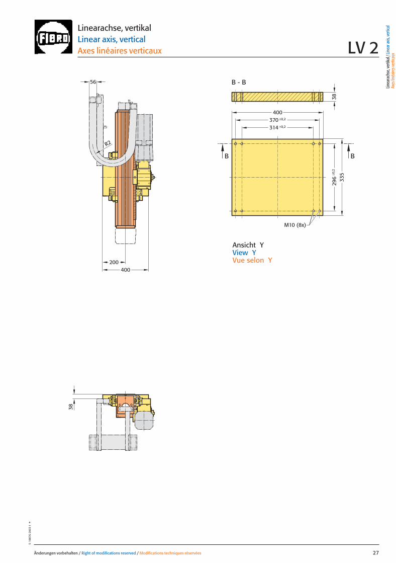
296
±0,2
±0,2370±0,2314
200400
56
R2
38
B B
400
335
38
M10 (8x)
B - B
Änderungen vorbehalten / Right of modifications reserved / Modifications techniques réservées 27
5·18
876
·200
3·1
°
Ansicht YView YVue selon Y
Linearachse, vertikalLinear axis, verticalAxes linéaires verticaux LV 2
Linea
rach
se, v
ertik
al / L
inea
r axis
, ver
tical
Axes
linéa
ires v
ertic
aux
027 27.08.2004 5:26 Uhr Seite 1
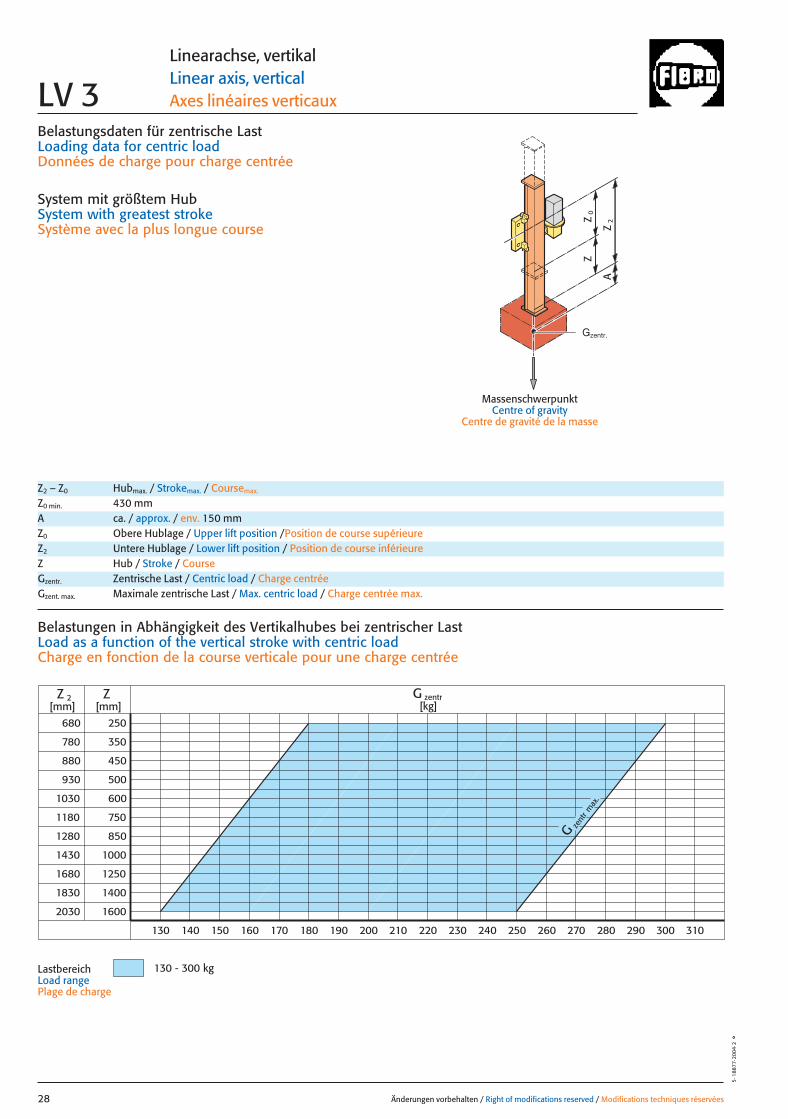
Belastungsdaten für zentrische LastLoading data for centric loadDonnées de charge pour charge centrée
System mit größtem HubSystem with greatest strokeSystème avec la plus longue course
MassenschwerpunktCentre of gravity
Centre de gravité de la masse
0Z
Z
2Z
A
zent
r
G
max
.
680
780
880
930
1030
1180
1280
1430
1680
1830
2030
250
350
450
500
600
750
850
1000
1250
1400
1600
Z
130 140 150 160 170 180 190 200 210 220 230 240 250 260 270 280 290 300 310
Z 2 G zentr[kg][mm] [mm]
130 - 300 kg
Änderungen vorbehalten / Right of modifications reserved / Modifications techniques réservées28
5·1
8877
·200
4·2
°
Linearachse, vertikalLinear axis, verticalAxes linéaires verticauxLV 3
Z2 – Z0 Hubmax. / Strokemax. / Coursemax.
Z0 min. 430 mmA ca. / approx. / env. 150 mmZ0 Obere Hublage / Upper lift position /Position de course supérieureZ2 Untere Hublage / Lower lift position / Position de course inférieureZ Hub / Stroke / CourseGzentr. Zentrische Last / Centric load / Charge centréeGzent. max. Maximale zentrische Last / Max. centric load / Charge centrée max.
Belastungen in Abhängigkeit des Vertikalhubes bei zentrischer LastLoad as a function of the vertical stroke with centric loadCharge en fonction de la course verticale pour une charge centrée
LastbereichLoad range Plage de charge
Gzentr.
028 27.08.2004 5:26 Uhr Seite 2

= Gexzentr.y
Änderungen vorbehalten / Right of modifications reserved / Modifications techniques réservées 29
5·1
8878
·200
3·1
°
Belastungsdaten für exzentrische Lastbezogen auf Mitte Befestigungslochbild Z-Achse für x; y
Loading data for eccentric loadreferred to the centre of the fixing hole pattern Z-axis for x; y
Données de charge pour une charge excentréerapporté au centre du gabarit des trous de fixation axe Z pour x; y
G [kg], x [m], y [m]
= Gexzentr.x
Gzentr. � 0,225
(x + 0,225)
Gzentr. � 0,135
(y + 0,135)
Gzent. max. = Gzentr.
aus Diagrammfrom diagramvaleur relevée dans le diagramme
* Massenschwerpunkt* Centre of gravity* Centre de gravité de
la massex
Gy 2
Gy 1
Gx
2y
1y
0Z
Z
2Z
A
*
*
*
Linearachse, vertikalLinear axis, verticalAxes linéaires verticaux LV 3
Z0 Obere Hublage / Upper lift position / Position de course supérieureZ2 Untere Hublage / Lower lift position / Position de course inférieureZ Hub / Stroke / CourseA ca. / approx. / env. 150 mmGzentr. Zentrische Last / Centric load / Charge centréeGzent. max. Maximale zentrische Last / Max. centric load / Charge centrée max.Gexzent. max. Maximale exzentrische Last / Max. eccentric load / Charge excentrique max.
AntriebsdatenDrive data’sDonnées de l’entraînement
GeschwindigkeitSpeed [m/sec] 1 0,62 1,61Vitesse
Wiederholgenauigkeit der PositionierungRepeat accuracy for positioning [mm] +/– 0,05 +/– 0,05 +/– 0,05Fidélité de reproduction du positionnement
BeschleunigungAcceleration [m/sec2] 3 3 4Accélération
Servomotor Siemens 1FT 6 Siemens 1FT 6 Siemens 1FT 6Servo motor Siemens 1FK 7 Siemens 1FK 7 Siemens 1FK 7Servomoteur
UntersetzungStep-down ratio 10,2:1 16,1:1 10,2:1Taux de réduction
pneum. GewichtsausgleichPneumatic weight compensation [mm] 1x �80Équilibrage pneumatique de poids
Linea
rach
se, v
ertik
al / L
inea
r axis
, ver
tical
Axes
linéa
ires v
ertic
aux
029 27.08.2004 5:26 Uhr Seite 1
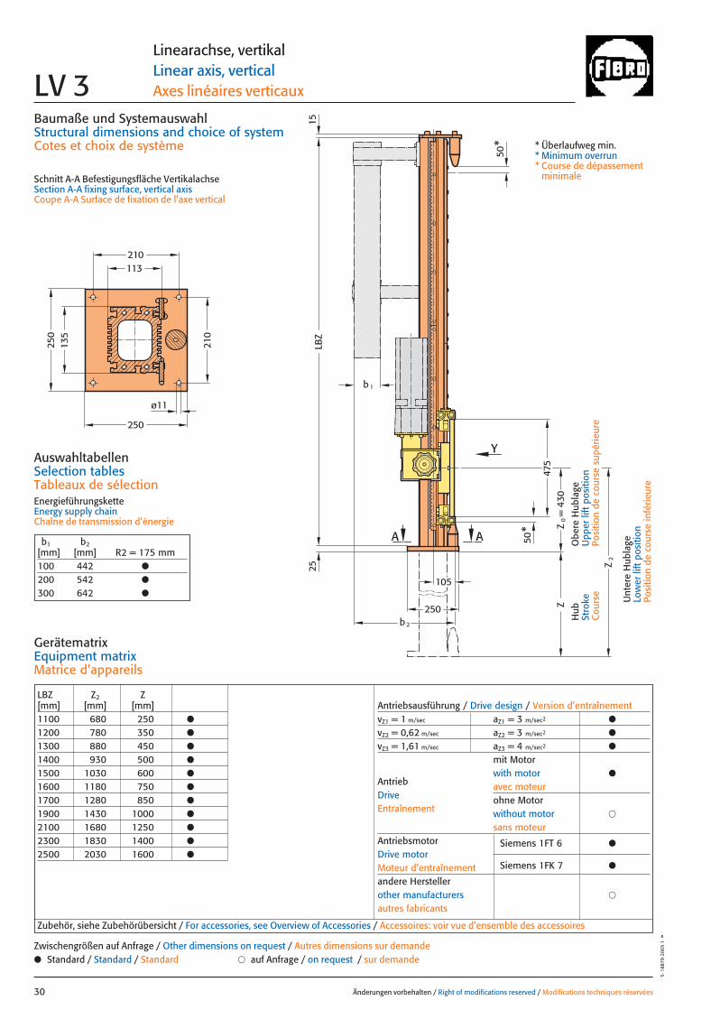
135
113
105
475
Y
AA
ø11
250
210
250
210
250
25LB
Z15
b 2
b1
Z2
Z
50*
50*
= 4
30Z
0
LBZ Z2 Z[mm] [mm] [mm]1100 680 250 ●
1200 780 350 ●
1300 880 450 ●
1400 930 500 ●
1500 1030 600 ●
1600 1180 750 ●
1700 1280 850 ●
1900 1430 1000 ●
2100 1680 1250 ●
2300 1830 1400 ●
2500 2030 1600 ●
Antriebsausführung / Drive design / Version d’entraînementvZ1 = 1 m/sec aZ1 = 3 m/sec2 ●
vZ2 = 0,62 m/sec aZ2 = 3 m/sec2 ●
vZ3 = 1,61 m/sec aZ3 = 4 m/sec2 ●
mit Motorwith motor ●
avec moteurohne Motorwithout motor �
sans moteurAntriebsmotor Siemens 1FT 6 ●Drive motorMoteur d’entraînement Siemens 1FK 7 ●
andere Herstellerother manufacturers �
autres fabricants
AntriebDriveEntraînement
Baumaße und SystemauswahlStructural dimensions and choice of systemCotes et choix de système
Schnitt A-A Befestigungsfläche VertikalachseSection A-A fixing surface, vertical axisCoupe A-A Surface de fixation de l’axe vertical
AuswahltabellenSelection tablesTableaux de sélectionEnergieführungsketteEnergy supply chainChaîne de transmission d’énergie
Änderungen vorbehalten / Right of modifications reserved / Modifications techniques réservées30
5·1
8879
·200
3·1
°
Linearachse, vertikalLinear axis, verticalAxes linéaires verticauxLV 3
GerätematrixEquipment matrixMatrice d’appareils
b1 b2[mm] [mm] R2 = 175 mm100 442 ●
200 542 ●
300 642 ●
Zubehör, siehe Zubehörübersicht / For accessories, see Overview of Accessories / Accessoires: voir vue d’ensemble des accessoires
● Standard / Standard / Standard � auf Anfrage / on request / sur demandeZwischengrößen auf Anfrage / Other dimensions on request / Autres dimensions sur demande
Hub
Stro
keC
ours
e
Obe
re H
ubla
geU
pper
lift
pos
ition
Posi
tion
de c
ours
e su
périe
ure
Unt
ere
Hub
lage
Low
er li
ft p
ositi
onPo
sitio
n de
cou
rse
infé
rieur
e
* Überlaufweg min.* Minimum overrun* Course de dépassement
minimale
030 27.08.2004 5:27 Uhr Seite 2
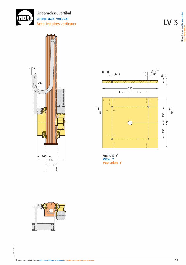
260520
150
150
170170
B - B
520
475
B B
M12
H7ø18M12
4,5
56
R2
25
Änderungen vorbehalten / Right of modifications reserved / Modifications techniques réservées 31
5·18
880
·200
3·1
°
Ansicht YView YVue selon Y
Linearachse, vertikalLinear axis, verticalAxes linéaires verticaux LV 3
Linea
rach
se, v
ertik
al / L
inea
r axis
, ver
tical
Axes
linéa
ires v
ertic
aux
031 27.08.2004 5:27 Uhr Seite 1
Belastungsdaten für zentrische LastLoading data for centric loadDonnées de charge pour charge centrée
System mit größtem HubSystem with greatest strokeSystème avec la plus longue course
MassenschwerpunktCentre of gravity
Centre de gravité de la masse
0Z
Z
2Z
A
G zentr
max.
810
910
1010
1060
1160
1310
1410
1560
1810
1960
2160
250
350
450
500
600
750
850
1000
1250
1400
1600
Z
360
Z 2[mm] [mm]
350340330320310300290280270260 370 380 390 400 410 420 430 440 450 460
G zentr[kg]
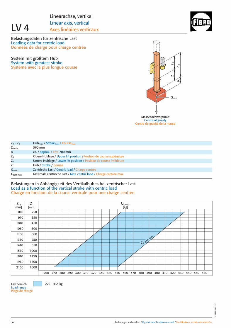
270 - 435 kg
Änderungen vorbehalten / Right of modifications reserved / Modifications techniques réservées32
5·1
8881
·200
4·2
°
Linearachse, vertikalLinear axis, verticalAxes linéaires verticauxLV 4
Z2 – Z0 Hubmax. / Strokemax. / Coursemax.
Z0 min. 560 mmA ca. / approx. / env. 200 mmZ0 Obere Hublage / Upper lift position /Position de course supérieureZ2 Untere Hublage / Lower lift position / Position de course inférieureZ Hub / Stroke / CourseGzentr. Zentrische Last / Centric load / Charge centréeGzent. max. Maximale zentrische Last / Max. centric load / Charge centrée max.
Belastungen in Abhängigkeit des Vertikalhubes bei zentrischer LastLoad as a function of the vertical stroke with centric loadCharge en fonction de la course verticale pour une charge centrée
LastbereichLoad rangePlage de charge
Gzentr.
032 27.08.2004 5:27 Uhr Seite 2
= Gexzentr.y
Änderungen vorbehalten / Right of modifications reserved / Modifications techniques réservées 33
5·1
8882
·200
3·1
°
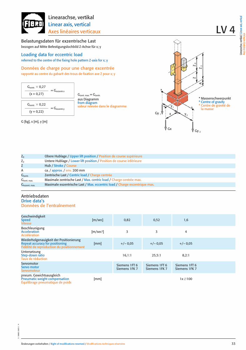
Belastungsdaten für exzentrische Lastbezogen auf Mitte Befestigungslochbild Z-Achse für x; y
Loading data for eccentric loadreferred to the centre of the fixing hole pattern Z-axis for x; y
Données de charge pour une charge excentréerapporté au centre du gabarit des trous de fixation axe Z pour x; y
G [kg], x [m], y [m]
= Gexzentr.x
Gzentr. � 0,27
(x + 0,27)
Gzentr. � 0,22
(y + 0,22)
Gzent. max. = Gzentr.
aus Diagrammfrom diagramvaleur relevée dans le diagramme
* Massenschwerpunkt* Centre of gravity* Centre de gravité de
la massex
Gy 2
Gy 1
Gx
2y
1y
0Z
Z
2Z
A
*
*
*
Linearachse, vertikalLinear axis, verticalAxes linéaires verticaux LV 4
Z0 Obere Hublage / Upper lift position / Position de course supérieureZ2 Untere Hublage / Lower lift position / Position de course inférieureZ Hub / Stroke / CourseA ca. / approx. / env. 200 mmGzentr. Zentrische Last / Centric load / Charge centréeGzent. max. Maximale zentrische Last / Max. centric load / Charge centrée max.Gexzent. max. Maximale exzentrische Last / Max. eccentric load / Charge excentrique max.
AntriebsdatenDrive data’sDonnées de l’entraînement
GeschwindigkeitSpeed [m/sec] 0,82 0,52 1,6Vitesse
Wiederholgenauigkeit der PositionierungRepeat accuracy for positioning [mm] +/– 0,05 +/– 0,05 +/– 0,05Fidélité de reproduction du positionnement
BeschleunigungAcceleration [m/sec2] 3 3 4Accélération
Servomotor Siemens 1FT 6 Siemens 1FT 6 Siemens 1FT 6Servo motor Siemens 1FK 7 Siemens 1FK 7 Siemens 1FK 7Servomoteur
UntersetzungStep-down ratio 16,1:1 25,5:1 8,2:1Taux de réduction
pneum. GewichtsausgleichPneumatic weight compensation [mm] 1x �100Équilibrage pneumatique de poids
Linea
rach
se, v
ertik
al / L
inea
r axis
, ver
tical
Axes
linéa
ires v
ertic
aux
033 27.08.2004 5:27 Uhr Seite 1
141,5
b2
b1
Z2
Z63
0
269
Y
AA50
*50
*
= 5
60Z
0
6060
LBZ
106,5
160
160
269
210
240
210
M16 (4x)
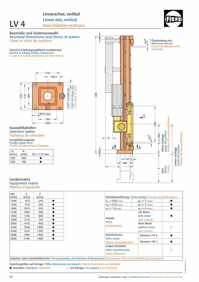
LBZ Z2 Z[mm] [mm] [mm]1400 810 250 ●
1500 910 350 ●
1600 1010 450 ●
1700 1060 500 ●
1800 1160 600 ●
1900 1310 750 ●
2000 1410 850 ●
2200 1560 1000 ●
2400 1810 1250 ●
2600 1960 1400 ●
2800 2160 1600 ●
Antriebsausführung / Drive design / Version d’entraînementvZ1 = 0,82 m/sec aZ1 = 3 m/sec2 ●
vZ2 = 0,52 m/sec aZ2 = 3 m/sec2 ●
vZ3 = 1,6 m/sec aZ3 = 4 m/sec2 ●
mit Motorwith motor ●
avec moteurohne Motorwithout motor �
sans moteurAntriebsmotor Siemens 1FT 6 ●Drive motorMoteur d’entraînement Siemens 1FK 7 ●
andere Herstellerother manufacturers �
autres fabricants
AntriebDriveEntraînement
Baumaße und SystemauswahlStructural dimensions and choice of systemCotes et choix de système
Schnitt A-A Befestigungsfläche VertikalachseSection A-A fixing surface, vertical axisCoupe A-A Surface de fixation de l’axe vertical
AuswahltabellenSelection tablesTableaux de sélectionEnergieführungsketteEnergy supply chainChaîne de transmission d’énergie
Änderungen vorbehalten / Right of modifications reserved / Modifications techniques réservées34
5·1
8883
·200
4·2w
°
Linearachse, vertikalLinear axis, verticalAxes linéaires verticauxLV 4
GerätematrixEquipment matrixMatrice d’appareils
b1 b2[mm] [mm] R2 = 175 mm200 666 ●
300 766 ●
Zubehör, siehe Zubehörübersicht / For accessories, see Overview of Accessories / Accessoires: voir vue d’ensemble des accessoires
● Standard / Standard / Standard � auf Anfrage / on request / sur demandeZwischengrößen auf Anfrage / Other dimensions on request / Autres dimensions sur demande
Hub
Stro
keC
ours
e
Obe
re H
ubla
geU
pper
lift
pos
ition
Posi
tion
de c
ours
e su
périe
ure
Unt
ere
Hub
lage
Low
er li
ft p
ositi
onPo
sitio
n de
cou
rse
infé
rieur
e
* Überlaufweg min.* Minimum overrun* Course de dépassement
minimale
�24
H8
4,5
tief (
2x)
�24
H8
4,5
deep
(2x
)�
24H
8pr
of. 4
,5 (
2x)
034 27.08.2004 5:27 Uhr Seite 2
30
305610
5
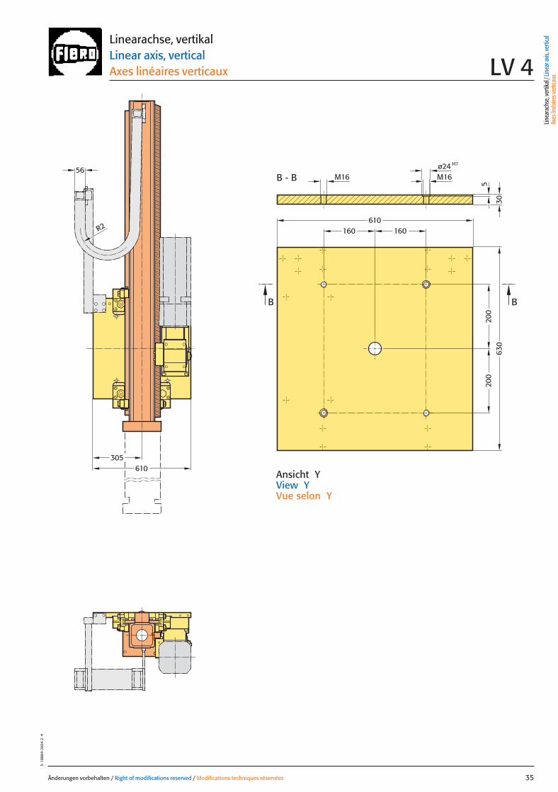
H7ø24M16
610160 160
200
200
630
M16
BB
B - B56
R2
Änderungen vorbehalten / Right of modifications reserved / Modifications techniques réservées 35
5·18
884
·200
4·2
°
Ansicht YView YVue selon Y
Linearachse, vertikalLinear axis, verticalAxes linéaires verticaux LV 4
Linea
rach
se, v
ertik
al / L
inea
r axis
, ver
tical
Axes
linéa
ires v
ertic
aux
035 27.08.2004 5:27 Uhr Seite 1
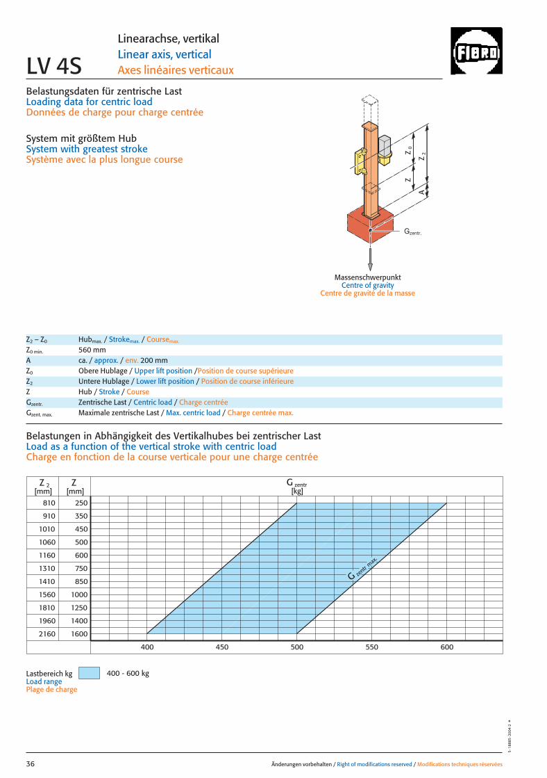
Belastungsdaten für zentrische LastLoading data for centric loadDonnées de charge pour charge centrée
System mit größtem HubSystem with greatest strokeSystème avec la plus longue course
MassenschwerpunktCentre of gravity
Centre de gravité de la masse
0Z
Z
2Z
A
G zentr
max.
810
910
1010
1060
1160
1310
1410
1560
1810
1960
2160
250
350
450
500
600
750
850
1000
1250
1400
1600
Z
500
Z 2[mm] [mm]
450400 550 600
G zentr[kg]
400 - 600 kg
Änderungen vorbehalten / Right of modifications reserved / Modifications techniques réservées36
5·1
8885
·200
4·2
°
Linearachse, vertikalLinear axis, verticalAxes linéaires verticauxLV 4S
Z2 – Z0 Hubmax. / Strokemax. / Coursemax.
Z0 min. 560 mmA ca. / approx. / env. 200 mmZ0 Obere Hublage / Upper lift position /Position de course supérieureZ2 Untere Hublage / Lower lift position / Position de course inférieureZ Hub / Stroke / CourseGzentr. Zentrische Last / Centric load / Charge centréeGzent. max. Maximale zentrische Last / Max. centric load / Charge centrée max.
Belastungen in Abhängigkeit des Vertikalhubes bei zentrischer Last Load as a function of the vertical stroke with centric loadCharge en fonction de la course verticale pour une charge centrée
Lastbereich kgLoad rangePlage de charge
Gzentr.
036 27.08.2004 5:27 Uhr Seite 2

= Gexzentr.y
Änderungen vorbehalten / Right of modifications reserved / Modifications techniques réservées 37
5·1
8886
·200
3·1
°
Belastungsdaten für exzentrische Lastbezogen auf Mitte Befestigungslochbild Z-Achse für x; y
Loading data for eccentric loadreferred to the centre of the fixing hole pattern Z-axis for x; y
Données de charge pour une charge excentréerapporté au centre du gabarit des trous de fixation axe Z pour x; y
G [kg], x [m], y [m]
= Gexzentr.x
Gzentr. � 0,27
(x + 0,27)
Gzentr. � 0,22
(y + 0,22)
Gzent. max. = Gzentr.
aus Diagrammfrom diagramvaleur relevée dans le diagramme
* Massenschwerpunkt* Centre of gravity* Centre de gravité de
la massex
Gy 2
Gy 1
Gx
2y
1y
0Z
Z
2Z
A
*
*
*
Linearachse, vertikalLinear axis, verticalAxes linéaires verticaux LV 4S
Z0 Obere Hublage / Upper lift position / Position de course supérieureZ2 Untere Hublage / Lower lift position / Position de course inférieureZ Hub / Stroke / CourseA ca. / approx. / env. 200 mmGzentr. Zentrische Last / Centric load / Charge centréeGzent. max. Maximale zentrische Last / Max. centric load / Charge centrée max.Gexzent. max. Maximale exzentrische Last / Max. eccentric load / Charge excentrique max.
AntriebsdatenDrive data’sDonnées de l’entraînement
GeschwindigkeitSpeed [m/sec] 1 0,55 1,6Vitesse
Wiederholgenauigkeit der PositionierungRepeat accuracy for positioning [mm] +/– 0,05 +/– 0,05 +/– 0,05Fidélité de reproduction du positionnement
BeschleunigungAcceleration [m/sec2] 3 3 4Accélération
Servomotor Siemens 1FT 6 Siemens 1FT 6 Siemens 1FT 6Servo motor Siemens 1FK 7 Siemens 1FK 7 Siemens 1FK 7Servomoteur
UntersetzungStep-down ratio 12,4:1 24,1:1 12,4:1Taux de réduction
pneum. GewichtsausgleichPneumatic weight compensation [mm] 1x �100Équilibrage pneumatique de poids
Linea
rach
se, v
ertik
al / L
inea
r axis
, ver
tical
Axes
linéa
ires v
ertic
aux
037 27.08.2004 5:28 Uhr Seite 1
269
AA
Z2
Z63
0
Y
50*
50*
= 5
60Z
0
b 2
b1
141,5
6060
LBZ
106,5
160
160
269
210
240
210
M16 (4x)
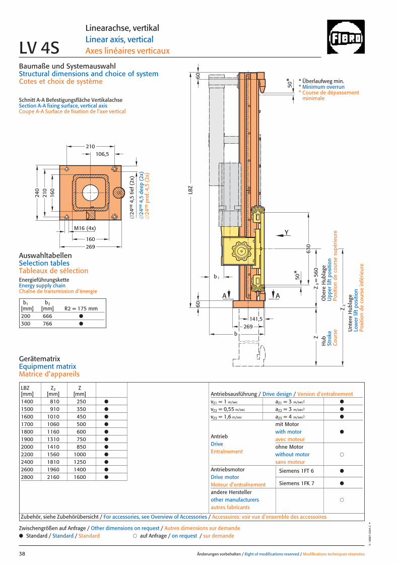
LBZ Z2 Z[mm] [mm] [mm]1400 810 250 ●
1500 910 350 ●
1600 1010 450 ●
1700 1060 500 ●
1800 1160 600 ●
1900 1310 750 ●
2000 1410 850 ●
2200 1560 1000 ●
2400 1810 1250 ●
2600 1960 1400 ●
2800 2160 1600 ●
Antriebsausführung / Drive design / Version d’entraînementvZ1 = 1 m/sec aZ1 = 3 m/sec2 ●
vZ2 = 0,55 m/sec aZ2 = 3 m/sec2 ●
vZ3 = 1,6 m/sec aZ3 = 4 m/sec2 ●
mit Motorwith motor ●
avec moteurohne Motorwithout motor �
sans moteurAntriebsmotor Siemens 1FT 6 ●Drive motorMoteur d’entraînement Siemens 1FK 7 ●
andere Herstellerother manufacturers �
autres fabricants
AntriebDriveEntraînement
Baumaße und SystemauswahlStructural dimensions and choice of systemCotes et choix de système
Schnitt A-A Befestigungsfläche VertikalachseSection A-A fixing surface, vertical axisCoupe A-A Surface de fixation de l’axe vertical
AuswahltabellenSelection tablesTableaux de sélectionEnergieführungsketteEnergy supply chainChaîne de transmission d’énergie
Änderungen vorbehalten / Right of modifications reserved / Modifications techniques réservées38
5·1
8887
·200
4·2
°
Linearachse, vertikalLinear axis, verticalAxes linéaires verticauxLV 4S
GerätematrixEquipment matrixMatrice d’appareils
b1 b2[mm] [mm] R2 = 175 mm200 666 ●
300 766 ●
Zubehör, siehe Zubehörübersicht / For accessories, see Overview of Accessories / Accessoires: voir vue d’ensemble des accessoires
● Standard / Standard / Standard � auf Anfrage / on request / sur demandeZwischengrößen auf Anfrage / Other dimensions on request / Autres dimensions sur demande
Hub
Stro
keC
ours
e
Obe
re H
ubla
geU
pper
lift
pos
ition
Posi
tion
de c
ours
e su
périe
ure
Unt
ere
Hub
lage
Low
er li
ft p
ositi
onPo
sitio
n de
cou
rse
infé
rieur
e
* Überlaufweg min.* Minimum overrun* Course de dépassement
minimale
�24
H8
4,5
tief (
2x)
�24
H8
4,5
deep
(2x
)�
24H
8pr
of. 4
,5 (
2x)
038 27.08.2004 5:26 Uhr Seite 2
Änderungen vorbehalten / Right of modifications reserved / Modifications techniques réservées 39
5·18
888
·200
4·2
°
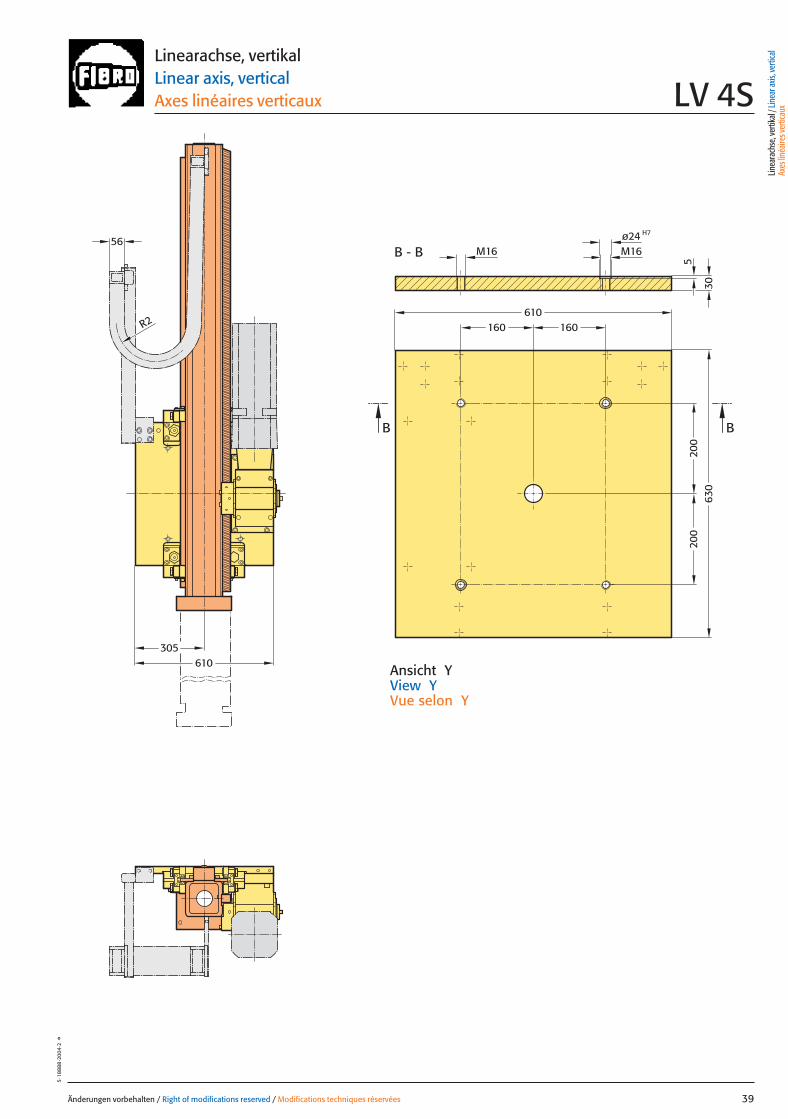
Ansicht YView YVue selon Y
Linearachse, vertikalLinear axis, verticalAxes linéaires verticaux LV 4S
305610
H7ø24M16
610160 160
200
200
630
M16
BB
B - B56
R2
30
5
Linea
rach
se, v
ertik
al / L
inea
r axis
, ver
tical
Axes
linéa
ires v
ertic
aux
039 27.08.2004 5:27 Uhr Seite 1
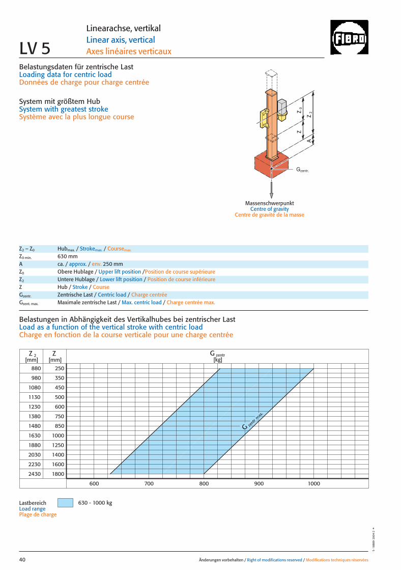
Belastungsdaten für zentrische LastLoading data for centric loadDonnées de charge pour charge centrée
System mit größtem HubSystem with greatest strokeSystème avec la plus longue course
MassenschwerpunktCentre of gravity
Centre de gravité de la masse
0Z
Z
2Z
A
880
980
1080
1130
1230
1380
1480
1630
1880
2030
2230
250
350
450
500
600
750
850
1000
1250
1400
1600
ZZ 2[mm] [mm]
800700600 900 1000
2430 1800
G zent
r max
.
G zentr[kg]
630 - 1000 kg
Änderungen vorbehalten / Right of modifications reserved / Modifications techniques réservées40
5·1
8889
·200
4·2
°
Linearachse, vertikalLinear axis, verticalAxes linéaires verticauxLV 5
Z2 – Z0 Hubmax. / Strokemax. / Coursemax.
Z0 min. 630 mmA ca. / approx. / env. 250 mmZ0 Obere Hublage / Upper lift position /Position de course supérieureZ2 Untere Hublage / Lower lift position / Position de course inférieureZ Hub / Stroke / CourseGzentr. Zentrische Last / Centric load / Charge centréeGzent. max. Maximale zentrische Last / Max. centric load / Charge centrée max.
Belastungen in Abhängigkeit des Vertikalhubes bei zentrischer Last Load as a function of the vertical stroke with centric loadCharge en fonction de la course verticale pour une charge centrée
LastbereichLoad rangePlage de charge
Gzentr.
040 27.08.2004 5:27 Uhr Seite 2
= Gexzentr.y
Änderungen vorbehalten / Right of modifications reserved / Modifications techniques réservées 41
5·1
8890
·200
3·1
°
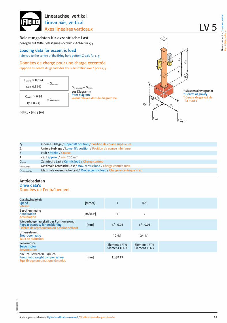
Belastungsdaten für exzentrische Lastbezogen auf Mitte Befestigungslochbild Z-Achse für x; y
Loading data for eccentric loadreferred to the centre of the fixing hole pattern Z-axis for x; y
Données de charge pour une charge excentréerapporté au centre du gabarit des trous de fixation axe Z pour x; y
G [kg], x [m], y [m]
= Gexzentr.x
Gzentr. � 0,324
(x + 0,324)
Gzentr. � 0,24
(y + 0,24)
Gzent. max. = Gzentr.
aus Diagrammfrom diagramvaleur relevée dans le diagramme
* Massenschwerpunkt* Centre of gravity* Centre de gravité de
la massex
Gy 2
Gy 1
Gx
2y
1y
0Z
Z
2Z
A
*
*
*
Linearachse, vertikalLinear axis, verticalAxes linéaires verticaux LV 5
Z0 Obere Hublage / Upper lift position / Position de course supérieureZ2 Untere Hublage / Lower lift position / Position de course inférieureZ Hub / Stroke / CourseA ca. / approx. / env. 250 mmGzentr. Zentrische Last / Centric load / Charge centréeGzent. max. Maximale zentrische Last / Max. centric load / Charge centrée max.Gexzent. max. Maximale exzentrische Last / Max. eccentric load / Charge excentrique max.
AntriebsdatenDrive data’sDonnées de l’entraînement
GeschwindigkeitSpeed [m/sec] 1 0,5Vitesse
Wiederholgenauigkeit der PositionierungRepeat accuracy for positioning [mm] +/– 0,05 +/– 0,05Fidélité de reproduction du positionnement
BeschleunigungAcceleration [m/sec2] 2 2Accélération
Servomotor Siemens 1FT 6 Siemens 1FT 6Servo motor Siemens 1FK 7 Siemens 1FK 7Servomoteur
UntersetzungStep-down ratio 12,4:1 24,1:1Taux de réduction
pneum. GewichtsausgleichPneumatic weight compensation [mm] 1x �125Équilibrage pneumatique de poids
Linea
rach
se, v
ertik
al / L
inea
r axis
, ver
tical
Axes
linéa
ires v
ertic
aux
041 27.08.2004 5:28 Uhr Seite 1
b2
Z2
680
340
Y
AA
LBZ
50*
50*
Z=
630
Z0
b 1
28 163
158260
260
2518
0
310
300
M20 (4x)
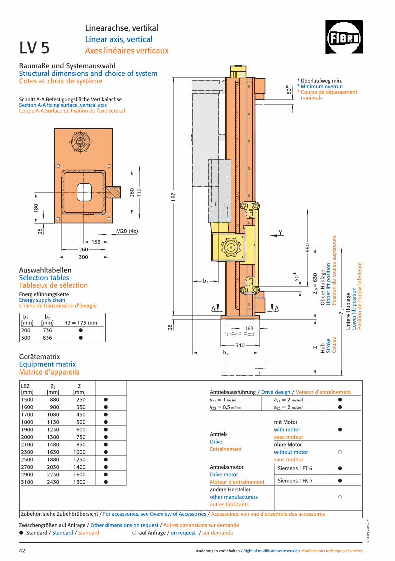
LBZ Z2 Z[mm] [mm] [mm]1500 880 250 ●
1600 980 350 ●
1700 1080 450 ●
1800 1130 500 ●
1900 1230 600 ●
2000 1380 750 ●
2100 1480 850 ●
2300 1630 1000 ●
2500 1880 1250 ●
2700 2030 1400 ●
2900 2230 1600 ●
3100 2430 1800 ●
Antriebsausführung / Drive design / Version d’entraînementvZ1 = 1 m/sec aZ1 = 2 m/sec2 ●
vZ2 = 0,5 m/sec aZ2 = 2 m/sec2 ●
mit Motorwith motor ●
avec moteurohne Motorwithout motor �
sans moteurAntriebsmotor Siemens 1FT 6 ●Drive motorMoteur d’entraînement Siemens 1FK 7 ●
andere Herstellerother manufacturers �
autres fabricants
AntriebDriveEntraînement
Baumaße und SystemauswahlStructural dimensions and choice of systemCotes et choix de système
Schnitt A-A Befestigungsfläche VertikalachseSection A-A fixing surface, vertical axisCoupe A-A Surface de fixation de l’axe vertical
AuswahltabellenSelection tablesTableaux de sélectionEnergieführungsketteEnergy supply chainChaîne de transmission d’énergie
Änderungen vorbehalten / Right of modifications reserved / Modifications techniques réservées42
5·1
8891
·200
4·2
°
Linearachse, vertikalLinear axis, verticalAxes linéaires verticauxLV 5
GerätematrixEquipment matrixMatrice d’appareils
b1 b2[mm] [mm] R2 = 175 mm200 736 ●
300 836 ●
Zubehör, siehe Zubehörübersicht / For accessories, see Overview of Accessories / Accessoires: voir vue d’ensemble des accessoires
● Standard / Standard / Standard � auf Anfrage / on request / sur demandeZwischengrößen auf Anfrage / Other dimensions on request / Autres dimensions sur demande
Hub
Stro
keC
ours
e
Obe
re H
ubla
geU
pper
lift
pos
ition
Posi
tion
de c
ours
e su
périe
ure
Unt
ere
Hub
lage
Low
er li
ft p
ositi
onPo
sitio
n de
cou
rse
infé
rieur
e
* Überlaufweg min.* Minimum overrun* Course de dépassement
minimale
042 27.08.2004 5:28 Uhr Seite 2
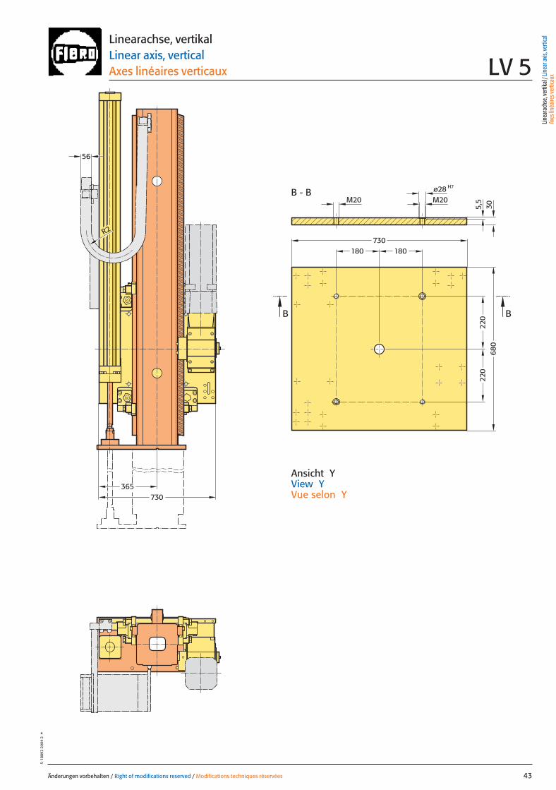
220
220
180180
680
730
BB
H7ø28M20M20
B - B
5,5
730
R2
56
36530
Änderungen vorbehalten / Right of modifications reserved / Modifications techniques réservées 43
5·18
892
·200
4·2
°
Ansicht YView YVue selon Y
Linearachse, vertikalLinear axis, verticalAxes linéaires verticaux LV 5
Linea
rach
se, v
ertik
al / L
inea
r axis
, ver
tical
Axes
linéa
ires v
ertic
aux
043 27.08.2004 5:28 Uhr Seite 1

Belastungsdaten für zentrische LastLoading data for centric loadDonnées de charge pour charge centrée
System mit größtem HubSystem with greatest strokeSystème avec la plus longue course
MassenschwerpunktCentre of gravity
Centre de gravité de la masse
0Z
Z
2Z
A
880
980
1080
1130
1230
1380
1480
1630
1880
2030
2230
250
350
450
500
600
750
850
1000
1250
1400
1600
ZZ 2[mm] [mm]
900700
2430 1800
Gze
ntr
max
.
800 1000 1100 1200 1300 1400 1500 1600
G zentr[kg]
850 - 1450 kg
Änderungen vorbehalten / Right of modifications reserved / Modifications techniques réservées44
5·1
8893
·200
4·2
°
Linearachse, vertikalLinear axis, verticalAxes linéaires verticauxLV 5S
Z2 – Z0 Hubmax. / Strokemax. / Coursemax.
Z0 min. 630 mmA ca. / approx. / env. 250 mmZ0 Obere Hublage / Upper lift position /Position de course supérieureZ2 Untere Hublage / Lower lift position / Position de course inférieureZ Hub / Stroke / CourseGzentr. Zentrische Last / Centric load / Charge centréeGzent. max. Maximale zentrische Last / Max. centric load / Charge centrée max.
Belastungen in Abhängigkeit des Vertikalhubes bei zentrischer Last Load as a function of the vertical stroke with centric loadCharge en fonction de la course verticale pour une charge centrée
LastbereichLoad rangePlage de charge
Gzentr.
044 27.08.2004 5:28 Uhr Seite 2
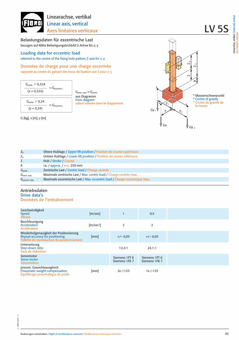
= Gexzentr.y
Änderungen vorbehalten / Right of modifications reserved / Modifications techniques réservées 45
5·1
8894
·200
3·1
°
Belastungsdaten für exzentrische Lastbezogen auf Mitte Befestigungslochbild Z-Achse für x; y
Loading data for eccentric loadreferred to the centre of the fixing hole pattern Z-axis for x; y
Données de charge pour une charge excentréerapporté au centre du gabarit des trous de fixation axe Z pour x; y
G [kg], x [m], y [m]
= Gexzentr.x
Gzentr. � 0,324
(x + 0,324)
Gzentr. � 0,24
(y + 0,24)
Gzent. max. = Gzentr.
aus Diagrammfrom diagramvaleur relevée dans le diagramme
* Massenschwerpunkt* Centre of gravity* Centre de gravité de
la massex
Gy 2
Gy 1
Gx
2y
1y
0Z
Z
2Z
A
*
*
*
Linearachse, vertikalLinear axis, verticalAxes linéaires verticaux LV 5S
Z0 Obere Hublage / Upper lift position / Position de course supérieureZ2 Untere Hublage / Lower lift position / Position de course inférieureZ Hub / Stroke / CourseA ca. / approx. / env. 250 mmGzentr. Zentrische Last / Centric load / Charge centréeGzent. max. Maximale zentrische Last / Max. centric load / Charge centrée max.Gexzent. max. Maximale exzentrische Last / Max. eccentric load / Charge excentrique max.
AntriebsdatenDrive data’sDonnées de l’entraînement
GeschwindigkeitSpeed [m/sec] 1 0,5Vitesse
Wiederholgenauigkeit der PositionierungRepeat accuracy for positioning [mm] +/– 0,05 +/– 0,05Fidélité de reproduction du positionnement
BeschleunigungAcceleration [m/sec2] 2 2Accélération
Servomotor Siemens 1FT 6 Siemens 1FT 6Servo motor Siemens 1FK 7 Siemens 1FK 7Servomoteur
UntersetzungStep-down ratio 12,4:1 24,1:1Taux de réduction
pneum. GewichtsausgleichPneumatic weight compensation [mm] 2x �125 1x �125Équilibrage pneumatique de poids
Linea
rach
se, v
ertik
al / L
inea
r axis
, ver
tical
Axes
linéa
ires v
ertic
aux
045 27.08.2004 5:28 Uhr Seite 1
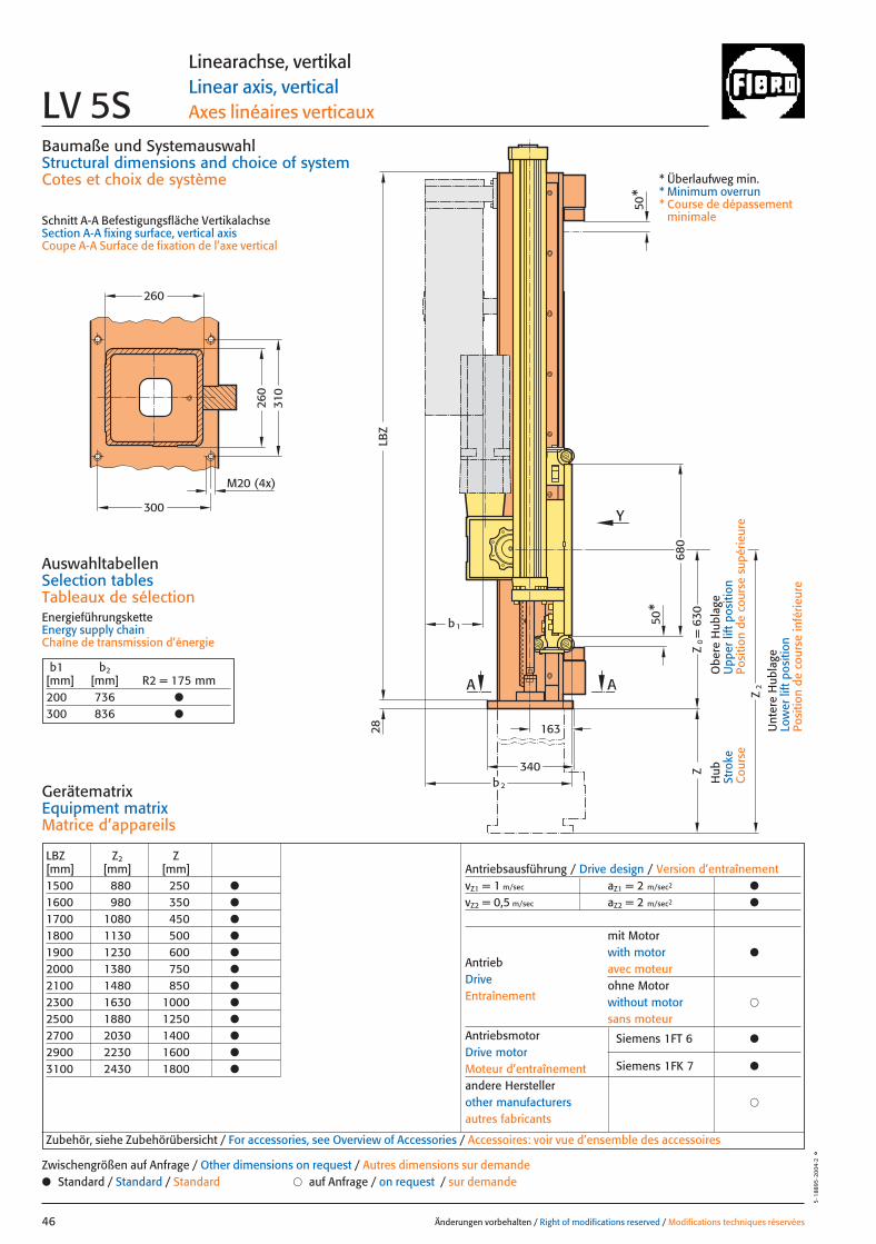
260
260
b 2
340
AA
LBZ
b 1
Z2
680
Y
50*
50*
Z=
630
Z0
310
300
M20 (4x)
28 163
LBZ Z2 Z[mm] [mm] [mm]1500 880 250 ●
1600 980 350 ●
1700 1080 450 ●
1800 1130 500 ●
1900 1230 600 ●
2000 1380 750 ●
2100 1480 850 ●
2300 1630 1000 ●
2500 1880 1250 ●
2700 2030 1400 ●
2900 2230 1600 ●
3100 2430 1800 ●
Antriebsausführung / Drive design / Version d’entraînementvZ1 = 1 m/sec aZ1 = 2 m/sec2 ●
vZ2 = 0,5 m/sec aZ2 = 2 m/sec2 ●
mit Motorwith motor ●
avec moteurohne Motorwithout motor �
sans moteurAntriebsmotor Siemens 1FT 6 ●Drive motorMoteur d’entraînement Siemens 1FK 7 ●
andere Herstellerother manufacturers �
autres fabricants
AntriebDriveEntraînement
Baumaße und SystemauswahlStructural dimensions and choice of systemCotes et choix de système
Schnitt A-A Befestigungsfläche VertikalachseSection A-A fixing surface, vertical axisCoupe A-A Surface de fixation de l’axe vertical
AuswahltabellenSelection tablesTableaux de sélectionEnergieführungsketteEnergy supply chainChaîne de transmission d’énergie
Änderungen vorbehalten / Right of modifications reserved / Modifications techniques réservées46
5·1
8895
·200
4·2
°
Linearachse, vertikalLinear axis, verticalAxes linéaires verticauxLV 5S
GerätematrixEquipment matrixMatrice d’appareils
b1 b2[mm] [mm] R2 = 175 mm200 736 ●
300 836 ●
Zubehör, siehe Zubehörübersicht / For accessories, see Overview of Accessories / Accessoires: voir vue d’ensemble des accessoires
● Standard / Standard / Standard � auf Anfrage / on request / sur demandeZwischengrößen auf Anfrage / Other dimensions on request / Autres dimensions sur demande
Hub
Stro
keC
ours
e
Obe
re H
ubla
geU
pper
lift
pos
ition
Posi
tion
de c
ours
e su
périe
ure
Unt
ere
Hub
lage
Low
er li
ft p
ositi
onPo
sitio
n de
cou
rse
infé
rieur
e
* Überlaufweg min.* Minimum overrun* Course de dépassement
minimale
046 27.08.2004 5:28 Uhr Seite 2
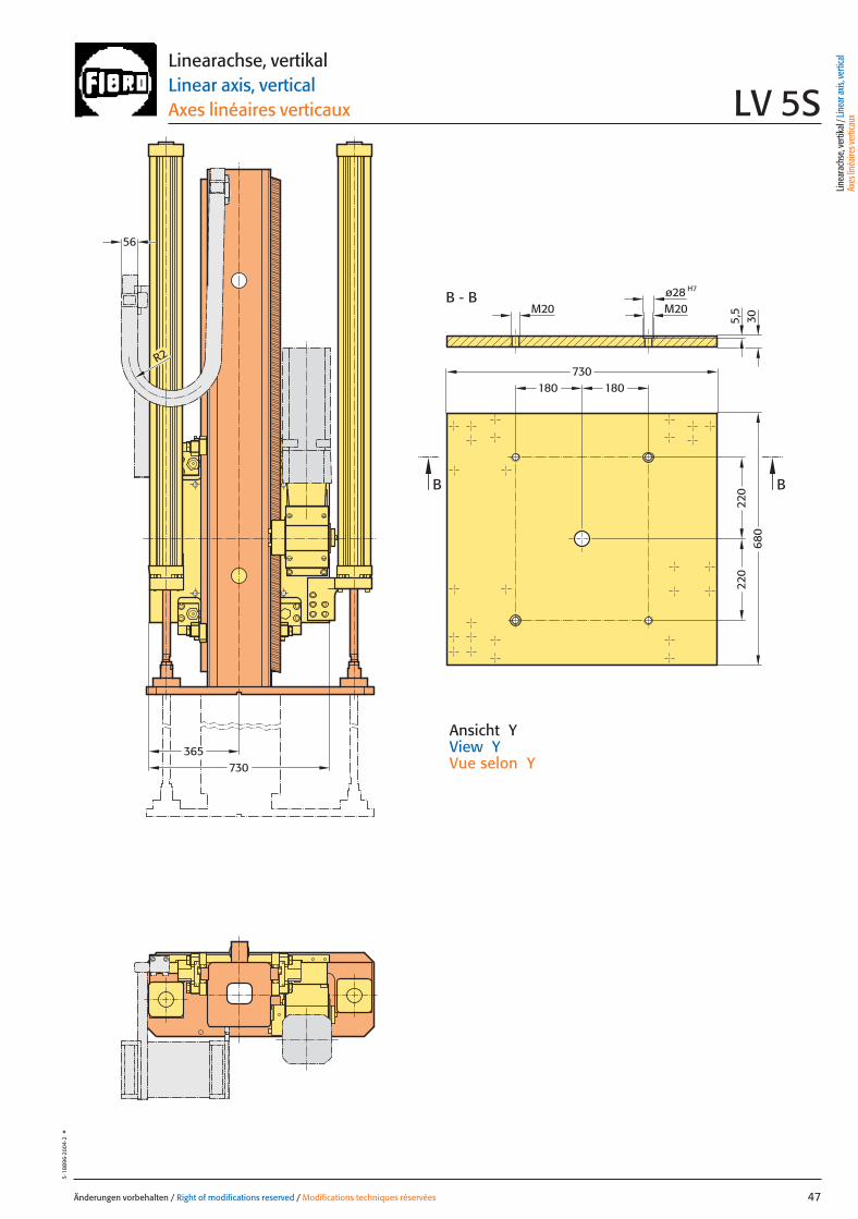
Änderungen vorbehalten / Right of modifications reserved / Modifications techniques réservées 47
5·18
896·
2004
·2°
Ansicht YView YVue selon Y
Linearachse, vertikalLinear axis, verticalAxes linéaires verticaux LV 5S
365730
220
220
180180
680
730
BB
H7ø28M20M20
B - B
R2
5,5
30
56
Linea
rach
se, v
ertik
al / L
inea
r axis
, ver
tical
Axes
linéa
ires v
ertic
aux
047 27.08.2004 5:28 Uhr Seite 1

Änderungen vorbehalten / Right of modifications reserved / Modifications techniques réservées48
5·18
897·
2003
·1°
048 27.08.2004 5:28 Uhr Seite 2

Änderungen vorbehalten / Right of modifications reserved / Modifications techniques réservées 49
5·18
898
·200
3·1
°
Linearachse, horizontal TypLinear axis, horizontal Type
Axes linéaires horizontal Type LH
Linea
rach
se, h
orizo
ntal
/ Lin
ear a
xis, h
orizo
ntal
Axes
linéa
ires h
orizo
ntal
049 27.08.2004 6:03 Uhr Seite 1
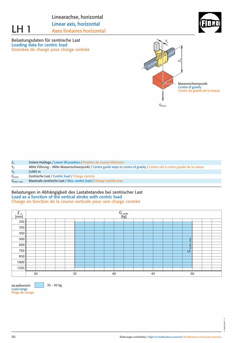
Belastungsdaten für zentrische LastLoading data for centric loadDonnées de charge pour charge centrée
MassenschwerpunktCentre of gravityCentre de gravité de la masse
Z2
0Y
zent
rG
max
.
250
350
450
500
1000
1250
Z 2 G zentr[kg][mm]
35 - 50 kg
600
750
850
30 35 40 45 50
Änderungen vorbehalten / Right of modifications reserved / Modifications techniques réservées50
5·18
XXX·
2004
·1°
Linearachse, horizontalLinear axis, horizontalAxes linéaires horizontalLH 1
Z2 Untere Hublage / Lower lift position / Position de course inférieureY0 Mitte Führung – Mitte Massenschwerpunkt / Centre guide ways to centre of gravity / Centre rail à centre gravité de la masseY0 0,085 mGzentr. Zentrische Last / Centric load / Charge centréeGzent. max. Maximale zentrische Last / Max. centric load / Charge centrée max.
Belastungen in Abhängigkeit des Lastabstandes bei zentrischer LastLoad as a function of the vertical stroke with centric loadCharge en fonction de la course verticale pour une charge centrée
wLastbereichLoad rangePlage de charge
Gzentr.
050 27.08.2004 6:02 Uhr Seite 2
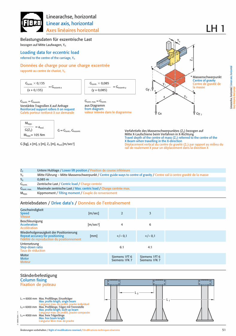
x
Gy 2
Gy 1
Gx
2y
1y
Z2
*
**
0Y
= Gexzentr.y
Änderungen vorbehalten / Right of modifications reserved / Modifications techniques réservées 51
5·18
XXX·
2004
·1°
Belastungsdaten für exzentrische Lastbezogen auf Mitte Laufwagen, Y0
Loading data for eccentric loadreferred to the centre of the carriage, Y0
Données de charge pour une charge excentréerapporté au centre de chariot, Y0
Verfahrtiefe des Massenschwerpunktes (Z2) bezogen auf Mitte X-Laufschiene beim Verfahren in X-RichtungTravel depth of the centre of mass (Z2) referred to the centre of the X Beam when travelling in the X-directionDéplacement vertical du centre de gravité (Z2) par rapport au milieu durail de roulement X pour un déplacement dans la direction X
G [kg], x [m], y [m], Z2 [m], axzul.[m/sec2]
= Gexzentr.x
Gzentr. � 0,135
(x + 0,135)
Gzentr. � 0,085
(y + 0,085)
Gzentr. = Gexzentr.
Verstärkte Tragrollen X auf AnfrageReinforced support rollers X on requestGalets porteur renforcé X sur demande
Gzent. max. = Gzentr.
aus Diagrammfrom diagramvaleur relevée dans le diagramme
* MassenschwerpunktCentre of gravityCentre de gravité dela masse
Linearachse, horizontalLinear axis, horizontalAxes linéaires horizontal LH 1
Antriebsdaten / Drive data’s / Données de l’entraînement
GeschwindigkeitSpeed [m/sec] 2 3Vitesse
Wiederholgenauigkeit der PositionierungRepeat accuracy for positioning [mm] +/– 0,1 +/– 0,1Fidélité de reproduction du positionnement
BeschleunigungAcceleration [m/sec2] 4 6Accélération
Motor Siemens 1FT 6 Siemens 1FT 6Motor Siemens 1FK 7 Siemens 1FK 7Moteur
UntersetzungStep-down ratio 6:1 4:1Taux de réduction
Z2 Untere Hublage / Lower lift position / Position de course inférieureY0 Mitte Führung – Mitte Massenschwerpunkt / Centre guide ways to centre of gravity / Centre rail à centre gravité de la masseY0 0,085 mGzentr. Zentrische Last / Centric load / Charge centréeGzent. max. Maximale zentrische Last / Max. centric load / Charge centrée max.Mkipp. Kippmoment / Tilting moment / Couple de renversement
= axzul.
Mkipp.
G(Z2)
Mkipp.= 105 NmG = Gzent., Gexzentr.
L 3
L 1
Ständerbefestigung Column fixingFixation de poteau
L1 = 6000 mm Max. Profillänge, EinzelträgerMax. profile length, single beam Longueur max. de profilé, poutre individuel
L2 = 6000 mm Max. Profillänge, Träger mit TrennstelleMax. profile length, built-up beam Longueur max. de profilé, poutre composée
L3 = 4000 mm Max. freie TrägerlängeMax. free beam length Longueur libre max. de poutre
Linea
rach
se, h
orizo
ntal
/ Lin
ear a
xis, h
orizo
ntal
Axes
linéa
ires h
orizo
ntal
051 27.08.2004 6:02 Uhr Seite 1
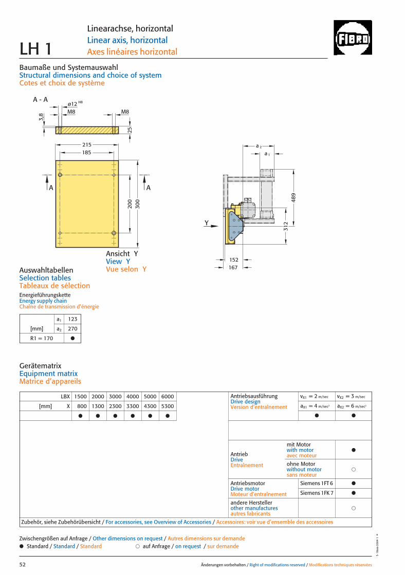
LBX 1500 2000 3000 4000 5000 6000
[mm] X 800 1300 2300 3300 4300 5300
● ● ● ● ● ●
AntriebsausführungDrive designVersion d’entraînement
vX1 = 2 m/sec vX2 = 3 m/sec
aX1 = 4 m/sec2 aX2 = 6 m/sec2
● ●
AntriebDriveEntraînement
AntriebsmotorDrive motorMoteur d’entraînement
�andere Herstellerother manufacturesautres fabricants
Zubehör, siehe Zubehörübersicht / For accessories, see Overview of Accessories / Accessoires: voir vue d’ensemble des accessoires
mit Motorwith motoravec moteur
●
�ohne Motorwithout motorsans moteur
152167
2520
030
0
215185 a 1
a 2
Y
M8M8
A - A H8ø12
3,8
A A
489
312
Baumaße und SystemauswahlStructural dimensions and choice of systemCotes et choix de système
AuswahltabellenSelection tablesTableaux de sélectionEnergieführungsketteEnergy supply chainChaîne de transmission d’énergie
Änderungen vorbehalten / Right of modifications reserved / Modifications techniques réservées52
5·18
xxx·
2004
·1°
Linearachse, horizontalLinear axis, horizontalAxes linéaires horizontalLH 1
GerätematrixEquipment matrixMatrice d’appareils
a1 123
[mm] a2 270
R1 = 170 ●
● Standard / Standard / Standard � auf Anfrage / on request / sur demandeZwischengrößen auf Anfrage / Other dimensions on request / Autres dimensions sur demande
Ansicht YView YVue selon Y
Siemens 1FT 6 ●
Siemens 1FK 7 ●
052 27.08.2004 6:02 Uhr Seite 2
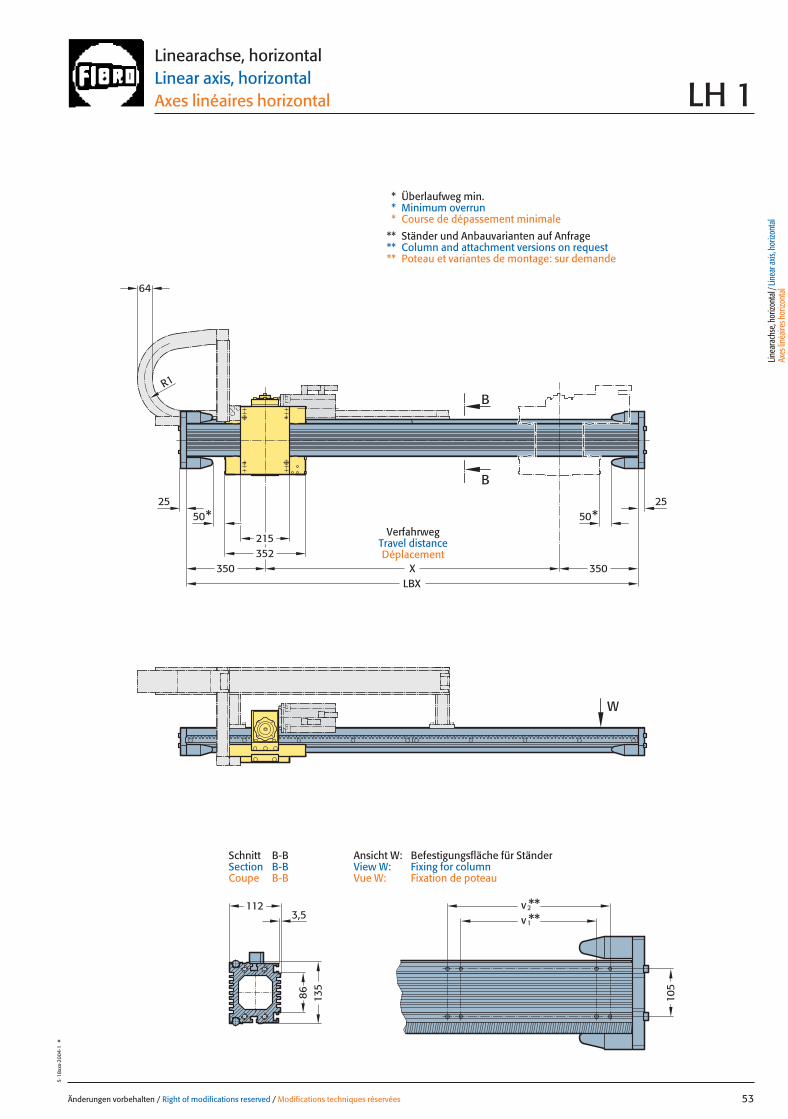
86
3,5
50* 50*
352215
LBX
v**2v**1
25 25
B
B
W
X
R1
64
350 350
112
135
105
Änderungen vorbehalten / Right of modifications reserved / Modifications techniques réservées 53
5·18
xxx·
2004
·1°
Linearachse, horizontalLinear axis, horizontalAxes linéaires horizontal LH 1
* Überlaufweg min.* Minimum overrun* Course de dépassement minimale
** Ständer und Anbauvarianten auf Anfrage** Column and attachment versions on request** Poteau et variantes de montage: sur demande
Ansicht W: Befestigungsfläche für StänderView W: Fixing for columnVue W: Fixation de poteau
Schnitt B-BSection B-BCoupe B-B
VerfahrwegTravel distanceDéplacement
Linea
rach
se, h
orizo
ntal
/ Lin
ear a
xis, h
orizo
ntal
Axes
linéa
ires h
orizo
ntal
053 27.08.2004 6:06 Uhr Seite 1
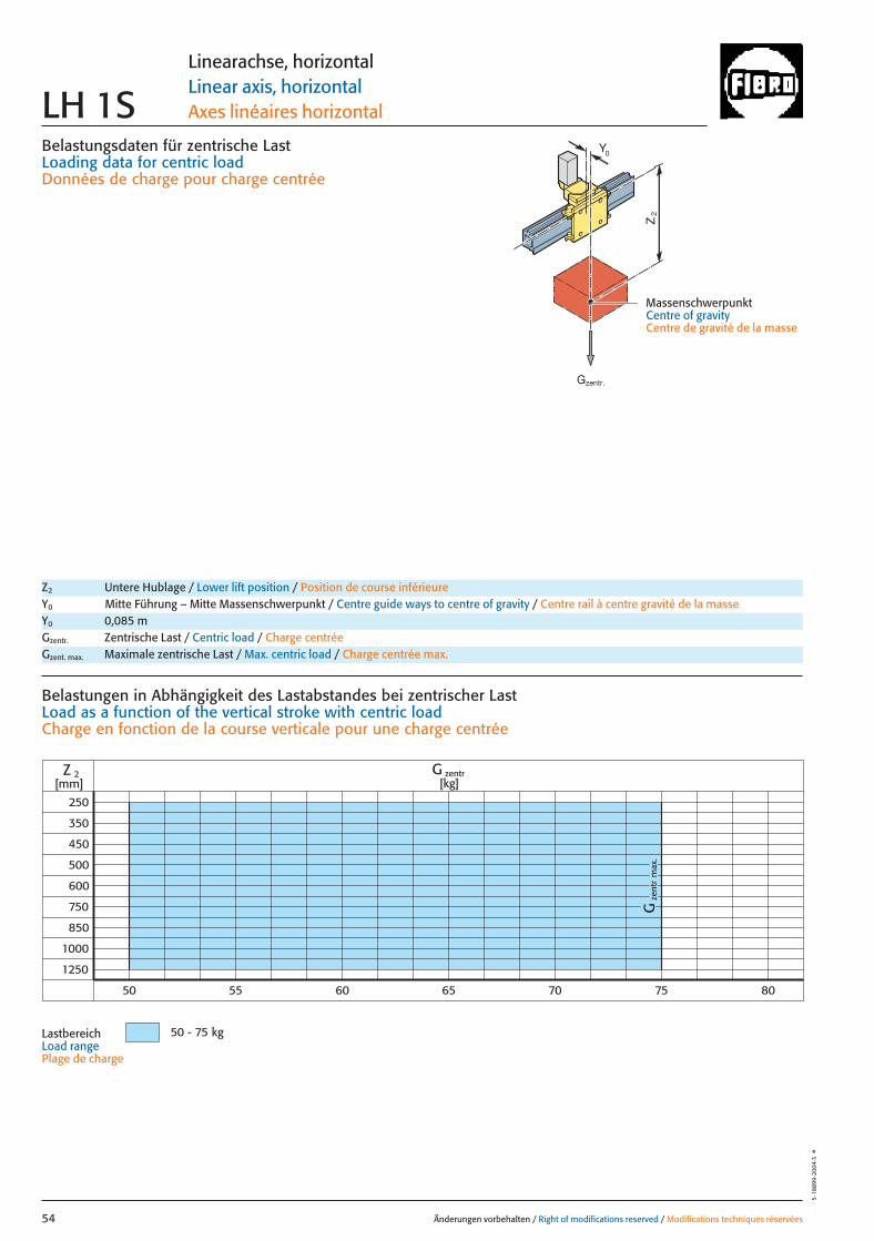
Belastungsdaten für zentrische LastLoading data for centric loadDonnées de charge pour charge centrée
MassenschwerpunktCentre of gravityCentre de gravité de la masse
Z2
0Y
zent
rG
max
.
250
350
450
500
1000
1250
Z 2 G zentr[kg][mm]
50 - 75 kg
600
750
850
50 55 60 65 70 75 80
Änderungen vorbehalten / Right of modifications reserved / Modifications techniques réservées54
5·18
899
·200
4·3
°
Linearachse, horizontalLinear axis, horizontalAxes linéaires horizontalLH 1S
Z2 Untere Hublage / Lower lift position / Position de course inférieureY0 Mitte Führung – Mitte Massenschwerpunkt / Centre guide ways to centre of gravity / Centre rail à centre gravité de la masseY0 0,085 mGzentr. Zentrische Last / Centric load / Charge centréeGzent. max. Maximale zentrische Last / Max. centric load / Charge centrée max.
Belastungen in Abhängigkeit des Lastabstandes bei zentrischer LastLoad as a function of the vertical stroke with centric loadCharge en fonction de la course verticale pour une charge centrée
LastbereichLoad rangePlage de charge
Gzentr.
054 27.08.2004 6:06 Uhr Seite 2

x
Gy 2
Gy 1
Gx
2y
1y
Z2
*
**
0Y
= Gexzentr.y
Änderungen vorbehalten / Right of modifications reserved / Modifications techniques réservées 55
5·18
900·
2004
·2°
Belastungsdaten für exzentrische Lastbezogen auf Mitte Laufwagen, Y0
Loading data for eccentric loadreferred to the centre of the carriage, Y0
Données de charge pour une charge excentréerapporté au centre de chariot, Y0
Verfahrtiefe des Massenschwerpunktes (Z2) bezogen auf Mitte X-Laufschiene beim Verfahren in X-RichtungTravel depth of the centre of mass (Z2) referred to the centre of the X Beam when travelling in the X-directionDéplacement vertical du centre de gravité (Z2) par rapport au milieu durail de roulement X pour un déplacement dans la direction X
G [kg], x [m], y [m], Z2 [m], axzul.[m/sec2]
= Gexzentr.x
Gzentr. � 0,135
(x + 0,135)
Gzentr. � 0,085
(y + 0,085)
Gzentr. = Gexzentr.
Verstärkte Tragrollen X auf AnfrageReinforced support rollers X on requestGalets porteur renforcé X sur demande
Gzent. max. = Gzentr.
aus Diagrammfrom diagramvaleur relevée dans le diagramme
* MassenschwerpunktCentre of gravityCentre de gravité dela masse
Linearachse, horizontalLinear axis, horizontalAxes linéaires horizontal LH 1S
Antriebsdaten / Drive data’s / Données de l’entraînement
GeschwindigkeitSpeed [m/sec] 2 3 4,5Vitesse
Wiederholgenauigkeit der PositionierungRepeat accuracy for positioning [mm] +/– 0,05 +/– 0,05 +/– 0,05Fidélité de reproduction du positionnement
BeschleunigungAcceleration [m/sec2] 4 6 6Accélération
Motor Siemens 1FT 6 Siemens 1FT 6 Siemens 1FT 6Motor Siemens 1FK 7 Siemens 1FK 7 Siemens 1FK 7Moteur
UntersetzungStep-down ratio 6:1 4:1 4:1Taux de réduction
Z2 Untere Hublage / Lower lift position / Position de course inférieureY0 Mitte Führung – Mitte Massenschwerpunkt / Centre guide ways to centre of gravity / Centre rail à centre gravité de la masseY0 0,085 mGzentr. Zentrische Last / Centric load / Charge centréeGzent. max. Maximale zentrische Last / Max. centric load / Charge centrée max.Mkipp. Kippmoment / Tilting moment / Couple de renversement
= axzul.
Mkipp.
G(Z2)
Mkipp.= 210 NmG = Gzent., Gexzentr.
L 3
L 1L 2
Ständerbefestigung Column fixingFixation de poteau
L1 = 10000 mm Max. Profillänge, EinzelträgerMax. profile length, single beam Longueur max. de profilé, poutre individuel
L2 = 10000 mm Max. Profillänge, Träger mit TrennstelleMax. profile length, built-up beam Longueur max. de profilé, poutre composée
L3 = 8000 mm Max. freie TrägerlängeMax. free beam length Longueur libre max. de poutre
TrennstellePoint of separationPoint de sectionnement
Linea
rach
se, h
orizo
ntal
/ Lin
ear a
xis, h
orizo
ntal
Axes
linéa
ires h
orizo
ntal
055 27.08.2004 6:06 Uhr Seite 1
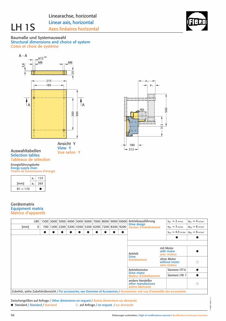
LBX 1500 2000 3000 4000 5000 6000 7000 8000 9000 10000
[mm] X 700 1200 2200 3200 4200 5200 6200 7200 8200 9200
● ● ● ● ● ● ● ● ● ●
AntriebsausführungDrive designVersion d’entraînement
vX1 = 2 m/sec aX1 = 4 m/sec2
vX2 = 3 m/sec aX2 = 6 m/sec2
vX3 = 4,5 m/sec aX3 = 6 m/sec2
● ●
AntriebDriveEntraînement
AntriebsmotorDrive motorMoteur d’entraînement
�andere Herstellerother manufacturesautres fabricants
Zubehör, siehe Zubehörübersicht / For accessories, see Overview of Accessories / Accessoires: voir vue d’ensemble des accessoires
mit Motorwith motoravec moteur
●
�ohne Motorwithout motorsans moteur
180212
500
312
a 2
a 1
2520
030
0215185
M8M8
A - A H8ø12
3,8
A A
Baumaße und SystemauswahlStructural dimensions and choice of systemCotes et choix de système
AuswahltabellenSelection tablesTableaux de sélectionEnergieführungsketteEnergy supply chainChaîne de transmission d’énergie
Änderungen vorbehalten / Right of modifications reserved / Modifications techniques réservées56
5·18
901·
2004
·2°
Linearachse, horizontalLinear axis, horizontalAxes linéaires horizontalLH 1S
GerätematrixEquipment matrixMatrice d’appareils
a1 123
[mm] a2 265
R1 = 170 ●
● Standard / Standard / Standard � auf Anfrage / on request / sur demandeZwischengrößen auf Anfrage / Other dimensions on request / Autres dimensions sur demande
Ansicht YView YVue selon Y
Siemens 1FT 6 ●
Siemens 1FK 7 ●
056 27.08.2004 6:06 Uhr Seite 2
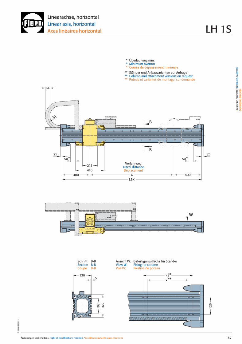
64
215410
LBX
163
130v**2v**1
X
50*25
50*25
B
B
W
R1
400 400
107
126
5
Änderungen vorbehalten / Right of modifications reserved / Modifications techniques réservées 57
5·18
902·
2004
·2°
Linearachse, horizontalLinear axis, horizontalAxes linéaires horizontal LH 1S
* Überlaufweg min.* Minimum overrun* Course de dépassement minimale
** Ständer und Anbauvarianten auf Anfrage** Column and attachment versions on request** Poteau et variantes de montage: sur demande
Ansicht W: Befestigungsfläche für StänderView W: Fixing for columnVue W: Fixation de poteau
Schnitt B-BSection B-BCoupe B-B
VerfahrwegTravel distanceDéplacement
Linea
rach
se, h
orizo
ntal
/ Lin
ear a
xis, h
orizo
ntal
Axes
linéa
ires h
orizo
ntal
057 27.08.2004 6:06 Uhr Seite 1
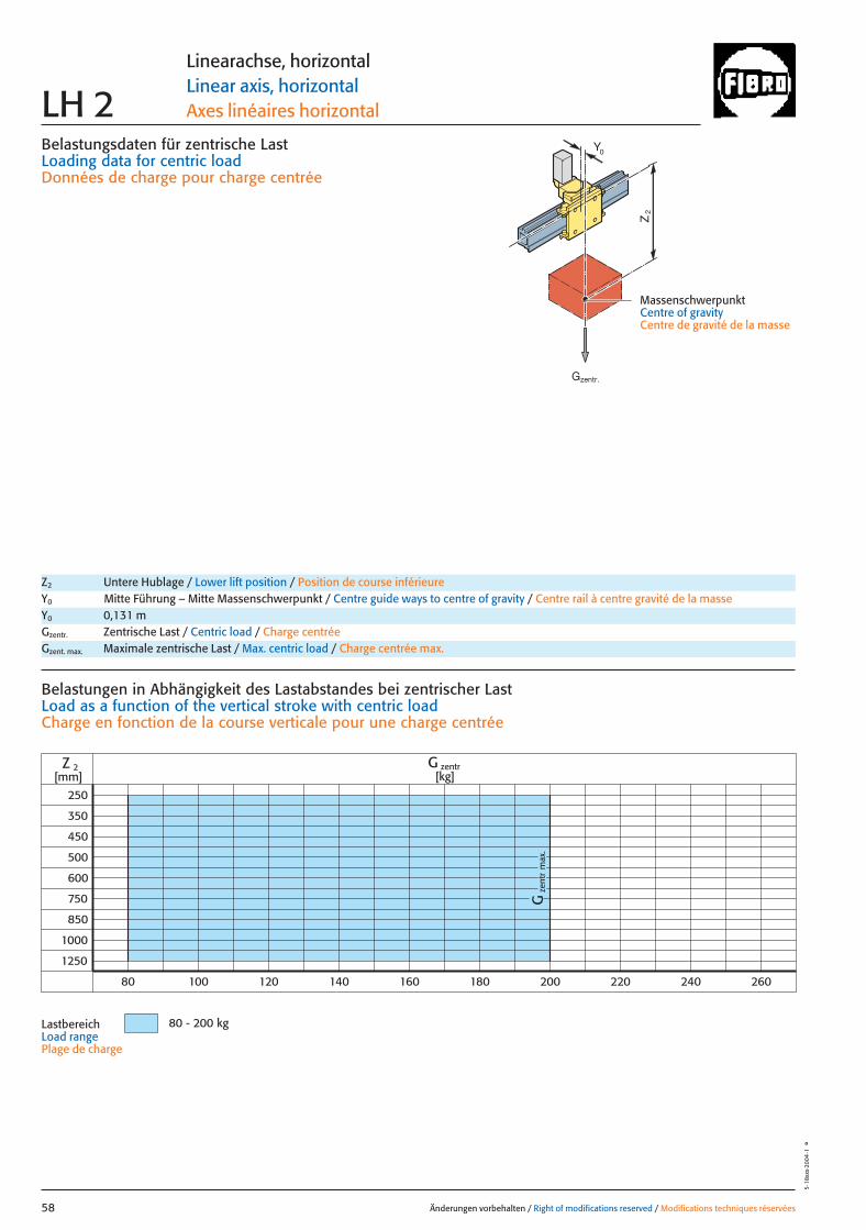
Belastungsdaten für zentrische LastLoading data for centric loadDonnées de charge pour charge centrée
MassenschwerpunktCentre of gravityCentre de gravité de la masse
Z2
0Y
zent
rG
max
.
250
350
450
500
1000
1250
Z 2 G zentr[kg][mm]
80 - 200 kg
600
750
850
80 100 120 140 160 180 200 220 240 260
Änderungen vorbehalten / Right of modifications reserved / Modifications techniques réservées58
5·18
xxx·
2004
·1°
Linearachse, horizontalLinear axis, horizontalAxes linéaires horizontalLH 2
Z2 Untere Hublage / Lower lift position / Position de course inférieureY0 Mitte Führung – Mitte Massenschwerpunkt / Centre guide ways to centre of gravity / Centre rail à centre gravité de la masseY0 0,131 mGzentr. Zentrische Last / Centric load / Charge centréeGzent. max. Maximale zentrische Last / Max. centric load / Charge centrée max.
Belastungen in Abhängigkeit des Lastabstandes bei zentrischer LastLoad as a function of the vertical stroke with centric loadCharge en fonction de la course verticale pour une charge centrée
LastbereichLoad rangePlage de charge
Gzentr.
058 27.08.2004 6:05 Uhr Seite 2
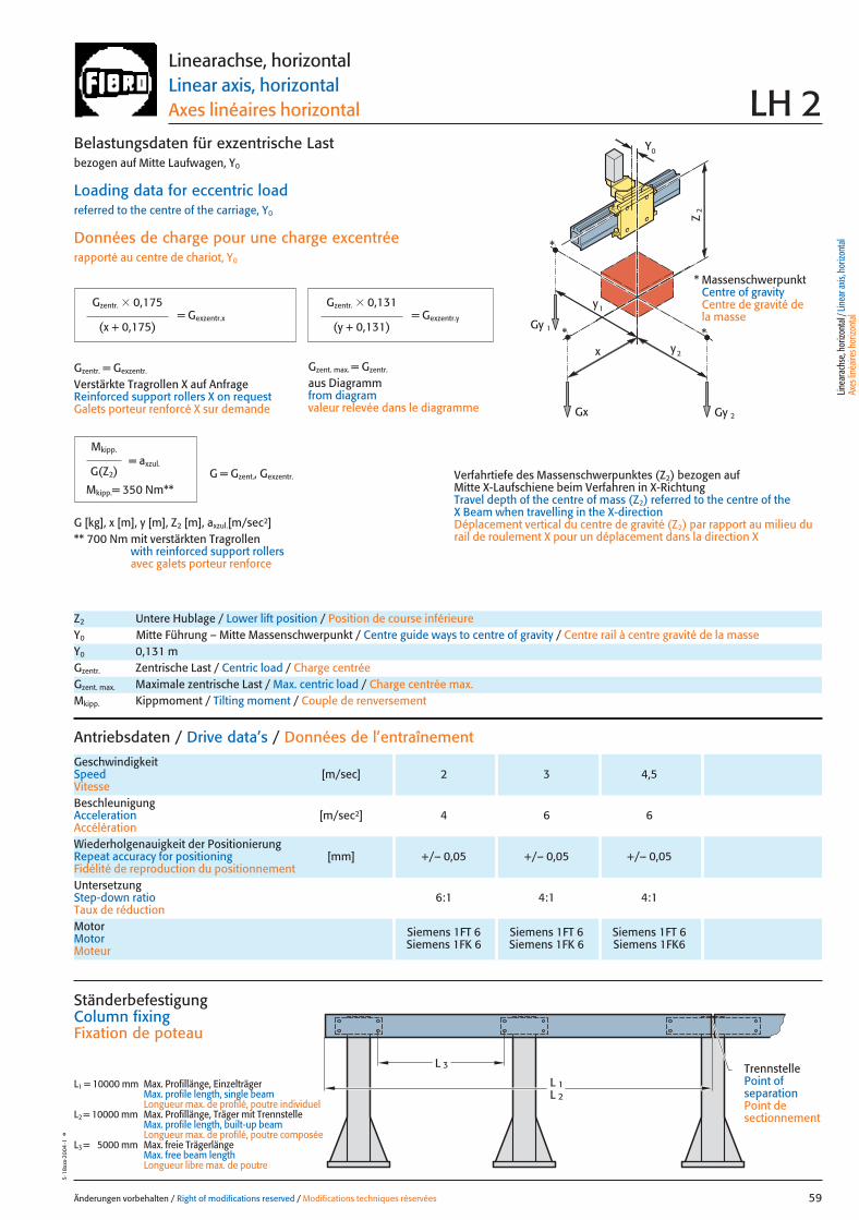
x
Gy 2
Gy 1
Gx
2y
1y
Z2
*
**
0Y
Änderungen vorbehalten / Right of modifications reserved / Modifications techniques réservées 59
5·18
xxx·
2004
·1°
Linearachse, horizontalLinear axis, horizontalAxes linéaires horizontal LH 2
Antriebsdaten / Drive data’s / Données de l’entraînement
GeschwindigkeitSpeed [m/sec] 2 3 4,5Vitesse
Wiederholgenauigkeit der PositionierungRepeat accuracy for positioning [mm] +/– 0,05 +/– 0,05 +/– 0,05Fidélité de reproduction du positionnement
BeschleunigungAcceleration [m/sec2] 4 6 6Accélération
Motor Siemens 1FT 6 Siemens 1FT 6 Siemens 1FT 6Motor Siemens 1FK 6 Siemens 1FK 6 Siemens 1FK6Moteur
UntersetzungStep-down ratio 6:1 4:1 4:1Taux de réduction
= Gexzentr.y
Belastungsdaten für exzentrische Lastbezogen auf Mitte Laufwagen, Y0
Loading data for eccentric loadreferred to the centre of the carriage, Y0
Données de charge pour une charge excentréerapporté au centre de chariot, Y0
Verfahrtiefe des Massenschwerpunktes (Z2) bezogen auf Mitte X-Laufschiene beim Verfahren in X-RichtungTravel depth of the centre of mass (Z2) referred to the centre of the X Beam when travelling in the X-directionDéplacement vertical du centre de gravité (Z2) par rapport au milieu durail de roulement X pour un déplacement dans la direction X
G [kg], x [m], y [m], Z2 [m], axzul.[m/sec2]** 700 Nm mit verstärkten Tragrollen
with reinforced support rollersavec galets porteur renforce
= Gexzentr.x
Gzentr. � 0,175
(x + 0,175)
Gzentr. � 0,131
(y + 0,131)
Gzentr. = Gexzentr.
Verstärkte Tragrollen X auf AnfrageReinforced support rollers X on requestGalets porteur renforcé X sur demande
Gzent. max. = Gzentr.
aus Diagrammfrom diagramvaleur relevée dans le diagramme
* MassenschwerpunktCentre of gravityCentre de gravité dela masse
Z2 Untere Hublage / Lower lift position / Position de course inférieureY0 Mitte Führung – Mitte Massenschwerpunkt / Centre guide ways to centre of gravity / Centre rail à centre gravité de la masseY0 0,131 mGzentr. Zentrische Last / Centric load / Charge centréeGzent. max. Maximale zentrische Last / Max. centric load / Charge centrée max.Mkipp. Kippmoment / Tilting moment / Couple de renversement
= axzul.
Mkipp.
G(Z2)
Mkipp.= 350 Nm**G = Gzent., Gexzentr.
L 3
L 1L 2
Ständerbefestigung Column fixingFixation de poteau
L1 = 10000 mm Max. Profillänge, EinzelträgerMax. profile length, single beam Longueur max. de profilé, poutre individuel
L2 = 10000 mm Max. Profillänge, Träger mit TrennstelleMax. profile length, built-up beam Longueur max. de profilé, poutre composée
L3 = 5000 mm Max. freie TrägerlängeMax. free beam length Longueur libre max. de poutre
TrennstellePoint of separationPoint de sectionnement
Linea
rach
se, h
orizo
ntal
/ Lin
ear a
xis, h
orizo
ntal
Axes
linéa
ires h
orizo
ntal
059 27.08.2004 6:03 Uhr Seite 1
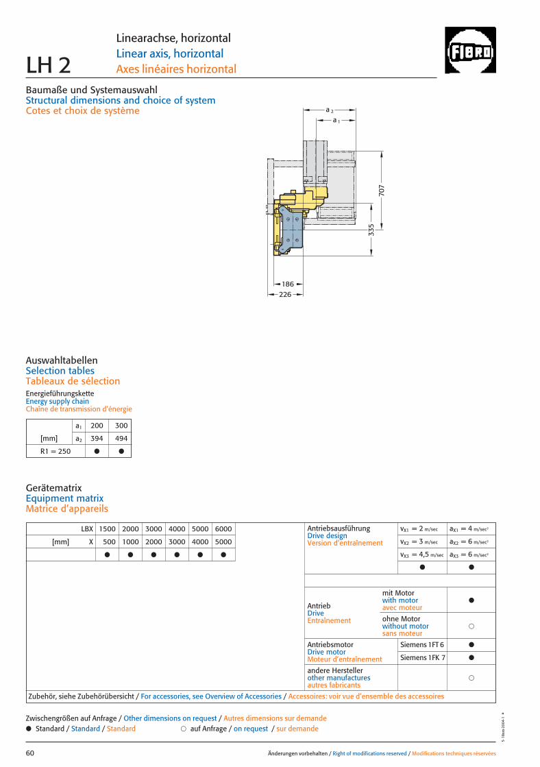
335
707
226186
a 1
a 2
Baumaße und SystemauswahlStructural dimensions and choice of systemCotes et choix de système
Änderungen vorbehalten / Right of modifications reserved / Modifications techniques réservées60
5·18
xxx·
2004
·1°
Linearachse, horizontalLinear axis, horizontalAxes linéaires horizontal LH 2
LBX 1500 2000 3000 4000 5000 6000
[mm] X 500 1000 2000 3000 4000 5000
● ● ● ● ● ●
AntriebsausführungDrive designVersion d’entraînement
vX1 = 2 m/sec aX1 = 4 m/sec2
vX2 = 3 m/sec aX2 = 6 m/sec2
vX3 = 4,5 m/sec aX3 = 6 m/sec2
● ●
AntriebDriveEntraînement
AntriebsmotorDrive motorMoteur d’entraînement
Siemens 1FT 6 ●
Siemens 1FK 7 ●
�andere Herstellerother manufacturesautres fabricants
Zubehör, siehe Zubehörübersicht / For accessories, see Overview of Accessories / Accessoires: voir vue d’ensemble des accessoires
mit Motorwith motoravec moteur
●
�ohne Motorwithout motorsans moteur
AuswahltabellenSelection tablesTableaux de sélectionEnergieführungsketteEnergy supply chainChaîne de transmission d’énergie
GerätematrixEquipment matrixMatrice d’appareils
a1 200 300
[mm] a2 394 494
R1 = 250 ● ●
● Standard / Standard / Standard � auf Anfrage / on request / sur demandeZwischengrößen auf Anfrage / Other dimensions on request / Autres dimensions sur demande
060 27.08.2004 6:05 Uhr Seite 2
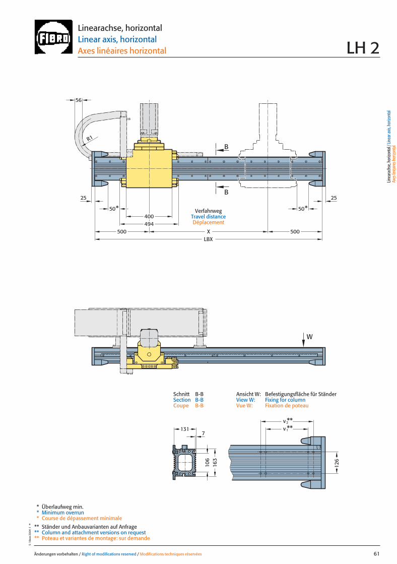
106
494400
50* 50*
R1
W
2525
500LBX
X 500
56
B
B
v**2v
1**
126
163
1317
Änderungen vorbehalten / Right of modifications reserved / Modifications techniques réservées 61
5·18
xxx·
2004
·1°
Linearachse, horizontalLinear axis, horizontalAxes linéaires horizontal LH 2
VerfahrwegTravel distanceDéplacement
* Überlaufweg min.* Minimum overrun* Course de dépassement minimale
** Ständer und Anbauvarianten auf Anfrage** Column and attachment versions on request** Poteau et variantes de montage: sur demande
Linea
rach
se, h
orizo
ntal
/ Lin
ear a
xis, h
orizo
ntal
Axes
linéa
ires h
orizo
ntal
Ansicht W: Befestigungsfläche für StänderView W: Fixing for columnVue W: Fixation de poteau
Schnitt B-BSection B-BCoupe B-B
061 27.08.2004 6:02 Uhr Seite 1
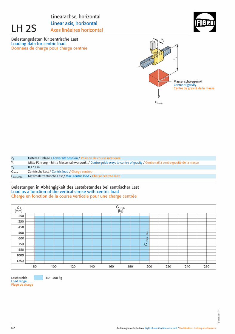
Belastungsdaten für zentrische LastLoading data for centric loadDonnées de charge pour charge centrée
MassenschwerpunktCentre of gravityCentre de gravité de la masse
Z2
0Y
zent
rG
max
.
250
350
450
500
1000
1250
Z 2 G zentr[kg][mm]
80 - 200 kg
600
750
850
80 100 120 140 160 180 200 220 240 260
Änderungen vorbehalten / Right of modifications reserved / Modifications techniques réservées62
5·18
903·
2004
·3°
Linearachse, horizontalLinear axis, horizontalAxes linéaires horizontalLH 2S
Z2 Untere Hublage / Lower lift position / Position de course inférieureY0 Mitte Führung – Mitte Massenschwerpunkt / Centre guide ways to centre of gravity / Centre rail à centre gravité de la masseY0 0,131 mGzentr. Zentrische Last / Centric load / Charge centréeGzent. max. Maximale zentrische Last / Max. centric load / Charge centrée max.
Belastungen in Abhängigkeit des Lastabstandes bei zentrischer LastLoad as a function of the vertical stroke with centric loadCharge en fonction de la course verticale pour une charge centrée
LastbereichLoad rangePlage de charge
Gzentr.
062 27.08.2004 6:06 Uhr Seite 2

x
Gy 2
Gy 1
Gx
2y
1y
Z2
*
**
0Y
Änderungen vorbehalten / Right of modifications reserved / Modifications techniques réservées 63
5·18
904·
2004
·2°
Linearachse, horizontalLinear axis, horizontalAxes linéaires horizontal LH 2S
Antriebsdaten / Drive data’s / Données de l’entraînement
GeschwindigkeitSpeed [m/sec] 2 3 4,5Vitesse
Wiederholgenauigkeit der PositionierungRepeat accuracy for positioning [mm] +/– 0,05 +/– 0,05 +/– 0,05Fidélité de reproduction du positionnement
BeschleunigungAcceleration [m/sec2] 4 6 6Accélération
Motor Siemens 1FT 6 Siemens 1FT 6 Siemens 1FT 6Motor Siemens 1FK 7 Siemens 1FK 7 Siemens 1FK 7Moteur
UntersetzungStep-down ratio 6:1 4:1 4:1Taux de réduction
= Gexzentr.y
Belastungsdaten für exzentrische Lastbezogen auf Mitte Laufwagen, Y0
Loading data for eccentric loadreferred to the centre of the carriage, Y0
Données de charge pour une charge excentréerapporté au centre de chariot, Y0
Verfahrtiefe des Massenschwerpunktes (Z2) bezogen auf Mitte X-Laufschiene beim Verfahren in X-RichtungTravel depth of the centre of mass (Z2) referred to the centre of the X Beam when travelling in the X-directionDéplacement vertical du centre de gravité (Z2) par rapport au milieu durail de roulement X pour un déplacement dans la direction X
G [kg], x [m], y [m], Z2 [m], axzul.[m/sec2]** 700 Nm mit verstärkten Tragrollen
with reinforced support rollersavec galets porteur renforce
= Gexzentr.x
Gzentr. � 0,175
(x + 0,175)
Gzentr. � 0,131
(y + 0,131)
Gzentr. = Gexzentr.
Verstärkte Tragrollen X auf AnfrageReinforced support rollers X on requestGalets porteur renforcé X sur demande
Gzent. max. = Gzentr.
aus Diagrammfrom diagramvaleur relevée dans le diagramme
* MassenschwerpunktCentre of gravityCentre de gravité dela masse
Z2 Untere Hublage / Lower lift position / Position de course inférieureY0 Mitte Führung – Mitte Massenschwerpunkt / Centre guide ways to centre of gravity / Centre rail à centre gravité de la masseY0 0,131 mGzentr. Zentrische Last / Centric load / Charge centréeGzent. max. Maximale zentrische Last / Max. centric load / Charge centrée max.Mkipp. Kippmoment / Tilting moment / Couple de renversement
= axzul.
Mkipp.
G(Z2)
Mkipp.= 350 Nm**G = Gzent., Gexzentr.
L 3
L 1L 2
Ständerbefestigung Column fixingFixation de poteau
L1 = 10000 mm Max. Profillänge, EinzelträgerMax. profile length, single beam Longueur max. de profilé, poutre individuel
L2 = 10000 mm Max. Profillänge, Träger mit TrennstelleMax. profile length, built-up beam Longueur max. de profilé, poutre composée
L3 = 8000 mm Max. freie TrägerlängeMax. free beam length Longueur libre max. de poutre
TrennstellePoint of separationPoint de sectionnement
Linea
rach
se, h
orizo
ntal
/ Lin
ear a
xis, h
orizo
ntal
Axes
linéa
ires h
orizo
ntal
063 27.08.2004 6:02 Uhr Seite 1
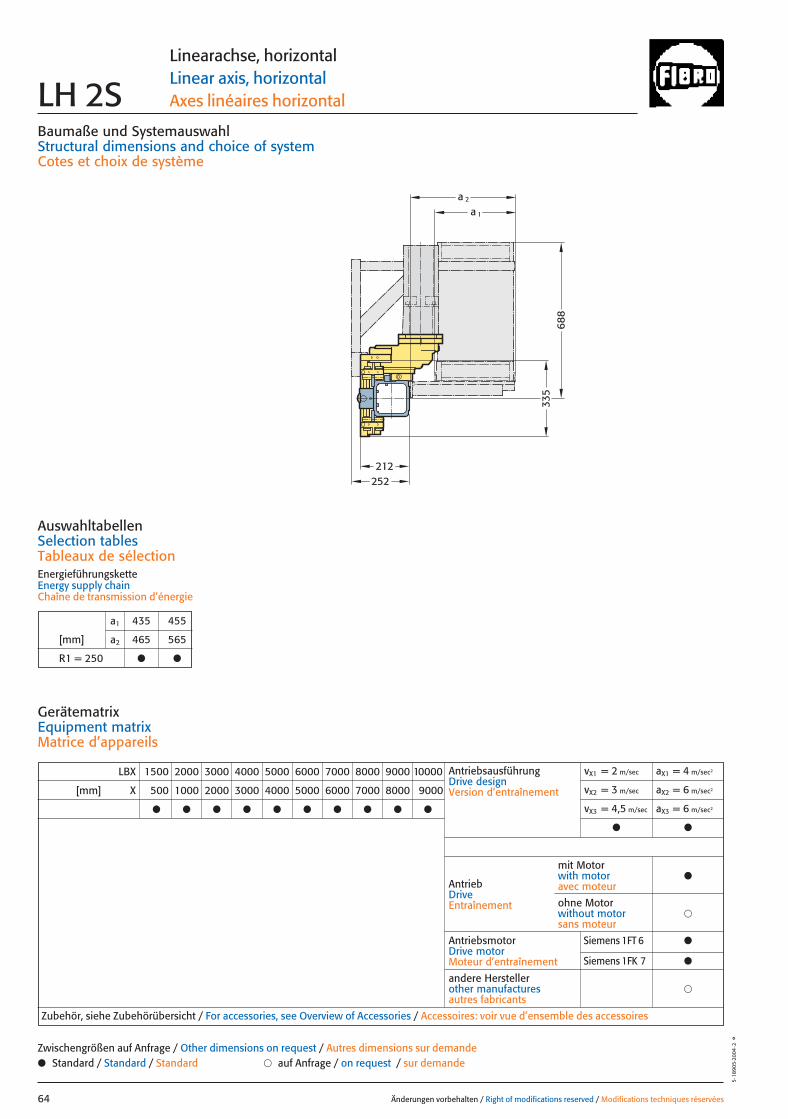
a 1
a 2
252212
335
688
Baumaße und SystemauswahlStructural dimensions and choice of systemCotes et choix de système
Änderungen vorbehalten / Right of modifications reserved / Modifications techniques réservées64
5·18
905·
2004
·2°
Linearachse, horizontalLinear axis, horizontalAxes linéaires horizontal LH 2S
LBX 1500 2000 3000 4000 5000 6000 7000 8000 9000 10000
[mm] X 500 1000 2000 3000 4000 5000 6000 7000 8000 9000
● ● ● ● ● ● ● ● ● ●
AntriebsausführungDrive designVersion d’entraînement
vX1 = 2 m/sec aX1 = 4 m/sec2
vX2 = 3 m/sec aX2 = 6 m/sec2
vX3 = 4,5 m/sec aX3 = 6 m/sec2
● ●
AntriebDriveEntraînement
AntriebsmotorDrive motorMoteur d’entraînement
�andere Herstellerother manufacturesautres fabricants
Zubehör, siehe Zubehörübersicht / For accessories, see Overview of Accessories / Accessoires: voir vue d’ensemble des accessoires
mit Motorwith motoravec moteur
●
�ohne Motorwithout motorsans moteur
AuswahltabellenSelection tablesTableaux de sélectionEnergieführungsketteEnergy supply chainChaîne de transmission d’énergie
GerätematrixEquipment matrixMatrice d’appareils
a1 435 455
[mm] a2 465 565
R1 = 250 ● ●
● Standard / Standard / Standard � auf Anfrage / on request / sur demandeZwischengrößen auf Anfrage / Other dimensions on request / Autres dimensions sur demande
Siemens 1FT 6 ●
Siemens 1FK 7 ●
064 27.08.2004 6:03 Uhr Seite 2
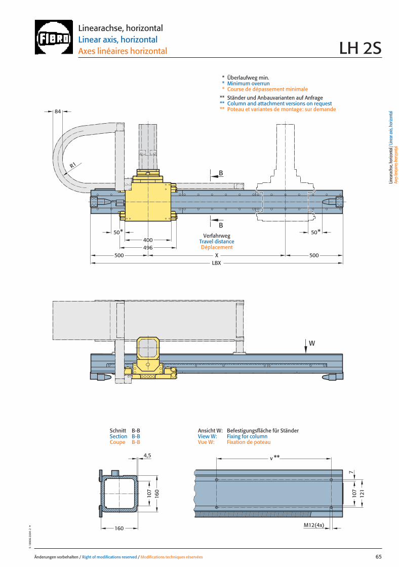
M12(4x)
50*50*400496
LBX
v **
X
B
B
W
4,5
160
107
710
712
1
84
R1
500 500
160
Änderungen vorbehalten / Right of modifications reserved / Modifications techniques réservées 65
5·18
906·
2004
·2°
Linearachse, horizontalLinear axis, horizontalAxes linéaires horizontal LH 2S
VerfahrwegTravel distanceDéplacement
* Überlaufweg min.* Minimum overrun* Course de dépassement minimale
** Ständer und Anbauvarianten auf Anfrage** Column and attachment versions on request** Poteau et variantes de montage: sur demande
Linea
rach
se, h
orizo
ntal
/ Lin
ear a
xis, h
orizo
ntal
Axes
linéa
ires h
orizo
ntal
Ansicht W: Befestigungsfläche für StänderView W: Fixing for columnVue W: Fixation de poteau
Schnitt B-BSection B-BCoupe B-B
065 27.08.2004 6:03 Uhr Seite 1

Belastungsdaten für zentrische LastLoading data for centric loadDonnées de charge pour charge centrée
MassenschwerpunktCentre of gravityCentre de gravité de la masse
Z2
0Y
zent
rG
max
.
G zentr[kg]
225 - 350 kg
2
250
350
450
500
600
750
850
1000
1250
1400
1600
Z[mm]
180 220 260 300 340200 240 280 320 360
Änderungen vorbehalten / Right of modifications reserved / Modifications techniques réservées66
5·18
907·
2004
·2°
Linearachse, horizontalLinear axis, horizontalAxes linéaires horizontalLH 3
Z2 Untere Hublage / Lower lift position / Position de course inférieureY0 Mitte Führung – Mitte Massenschwerpunkt / Centre guide ways to centre of gravity / Centre rail à centre gravité de la masseY0 0,135 mGzentr. Zentrische Last / Centric load / Charge centréeGzent. max. Maximale zentrische Last / Max. centric load / Charge centrée max.
Belastungen in Abhängigkeit des Lastabstandes bei zentrischer Last Load as a function of the vertical stroke with centric loadCharge en fonction de la course verticale pour une charge centrée
LastbereichLoad rangePlage de charge
Gzentr.
066 27.08.2004 6:03 Uhr Seite 2

x
Gy 2
Gy 1
Gx
2y
1y
Z2
*
**
0Y
Änderungen vorbehalten / Right of modifications reserved / Modifications techniques réservées 67
5·18
908·
2003
·1°
Linearachse, horizontalLinear axis, horizontalAxes linéaires horizontal LH 3
Antriebsdaten / Drive data’s / Données de l’entraînement
GeschwindigkeitSpeed [m/sec] 2 3 4,5Vitesse
Wiederholgenauigkeit der PositionierungRepeat accuracy for positioning [mm] +/– 0,05 +/– 0,05 +/– 0,05Fidélité de reproduction du positionnement
BeschleunigungAcceleration [m/sec2] 4 6 6Accélération
Motor Siemens 1FT 6 Siemens 1FT 6 Siemens 1FT 6Motor Siemens 1FK 7 Siemens 1FK 7 Siemens 1FK 7Moteur
UntersetzungStep-down ratio 6:1 4:1 4:1Taux de réduction
= Gexzentr.y
Belastungsdaten für exzentrische Lastbezogen auf Mitte Laufwagen, Y0
Loading data for eccentric loadreferred to the centre of the carriage, Y0
Données de charge pour une charge excentréerapporté au centre de chariot, Y0
Verfahrtiefe des Massenschwerpunktes (Z2) bezogen auf Mitte X-Laufschiene beim Verfahren in X-RichtungTravel depth of the centre of mass (Z2) referred to the centre of the X Beam when travelling in the X-directionDéplacement vertical du centre de gravité (Z2) par rapport au milieu durail de roulement X pour un déplacement dans la direction X
G [kg], x [m], y [m], Z2 [m], axzul.[m/sec2]** 1400 Nm mit verstärkten Tragrollen
with reinforced support rollersavec galets porteur renforce
= Gexzentr.x
Gzentr. � 0,225
(x + 0,225)
Gzentr. � 0,135
(y + 0,135)
Gzentr. = Gexzentr.
Verstärkte Tragrollen X auf AnfrageReinforced support rollers X on requestGalets porteur renforcé X sur demande
Gzent. max. = Gzentr.
aus Diagrammfrom diagramvaleur relevée dans le diagramme
* MassenschwerpunktCentre of gravityCentre de gravité dela masse
Z2 Untere Hublage / Lower lift position / Position de course inférieureY0 Mitte Führung – Mitte Massenschwerpunkt / Centre guide ways to centre of gravity / Centre rail à centre gravité de la masseY0 0,135 mGzentr. Zentrische Last / Centric load / Charge centréeGzent. max. Maximale zentrische Last / Max. centric load / Charge centrée max.Mkipp. Kippmoment / Tilting moment / Couple de renversement
= axzul.
Mkipp.
G(Z2)
Mkipp.= 700 Nm**G = Gzent., Gexzentr.
L 3
L 1L 2
Ständerbefestigung Column fixingFixation de poteau
L1 = 10000 mm Max. Profillänge, EinzelträgerMax. profile length, single beam Longueur max. de profilé, poutre individuel
L2 = 9000 mm Max. Profillänge, Träger mit TrennstelleMax. profile length, built-up beam Longueur max. de profilé, poutre composée
L3 = 6000 mm Max. freie TrägerlängeMax. free beam length Longueur libre max. de poutre
TrennstellePoint of separationPoint de sectionnement
Linea
rach
se, h
orizo
ntal
/ Lin
ear a
xis, h
orizo
ntal
Axes
linéa
ires h
orizo
ntal
067 27.08.2004 6:03 Uhr Seite 1
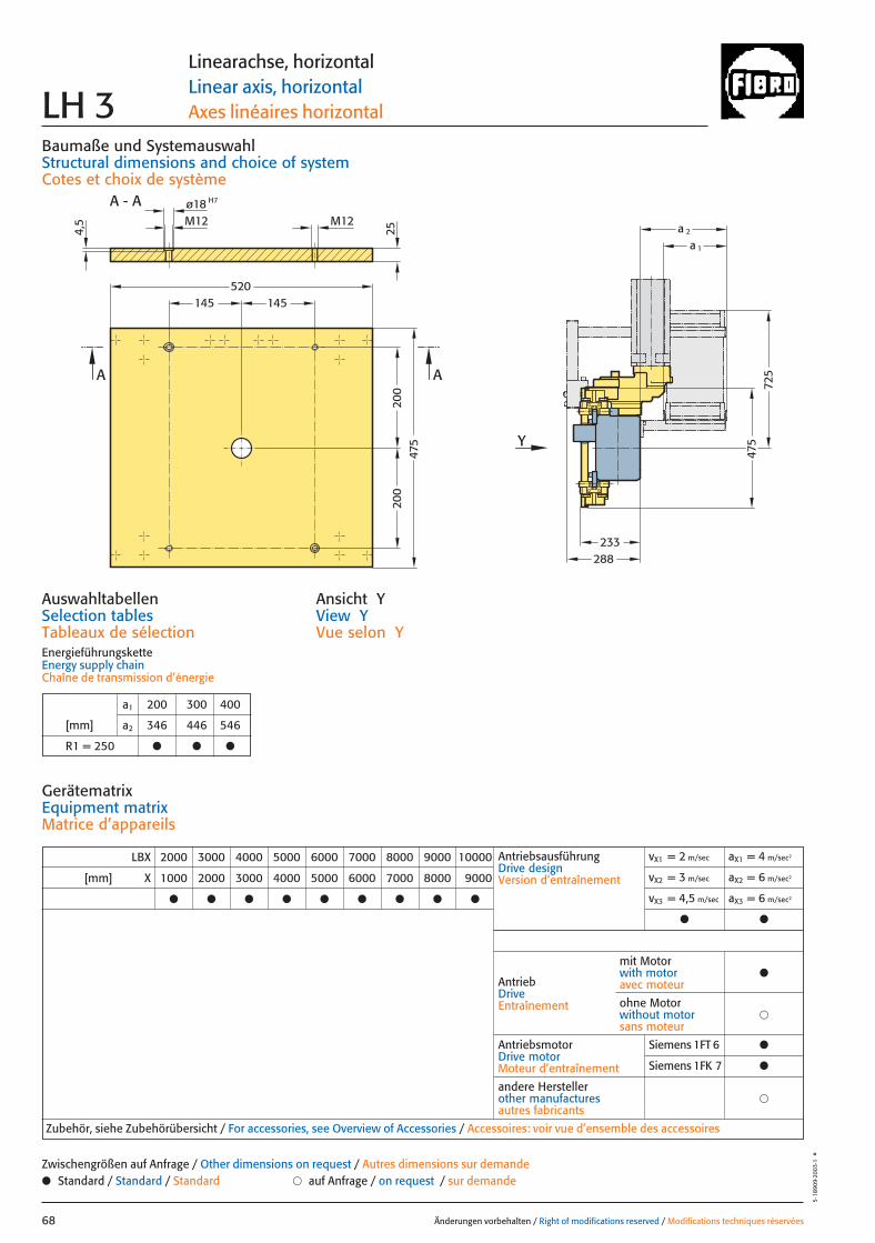
233
475
725
288
200
200
145145
Y
A - A
520
475
A A
M12
H7ø18M12
4,5
a 1
a 225
Baumaße und SystemauswahlStructural dimensions and choice of systemCotes et choix de système
Änderungen vorbehalten / Right of modifications reserved / Modifications techniques réservées68
5·18
909·
2003
·1°
Linearachse, horizontalLinear axis, horizontalAxes linéaires horizontal LH 3
Ansicht YView YVue selon Y
LBX 2000 3000 4000 5000 6000 7000 8000 9000 10000
[mm] X 1000 2000 3000 4000 5000 6000 7000 8000 9000
● ● ● ● ● ● ● ● ●
AntriebDriveEntraînement
AntriebsmotorDrive motorMoteur d’entraînement
�andere Herstellerother manufacturesautres fabricants
Zubehör, siehe Zubehörübersicht / For accessories, see Overview of Accessories / Accessoires: voir vue d’ensemble des accessoires
mit Motorwith motoravec moteur
●
�ohne Motorwithout motorsans moteur
AuswahltabellenSelection tablesTableaux de sélectionEnergieführungsketteEnergy supply chainChaîne de transmission d’énergie
GerätematrixEquipment matrixMatrice d’appareils
a1 200 300 400
[mm] a2 346 446 546
R1 = 250 ● ● ●
● Standard / Standard / Standard � auf Anfrage / on request / sur demandeZwischengrößen auf Anfrage / Other dimensions on request / Autres dimensions sur demande
Siemens 1FT 6 ●
Siemens 1FK 7 ●
AntriebsausführungDrive designVersion d’entraînement
vX1 = 2 m/sec aX1 = 4 m/sec2
vX2 = 3 m/sec aX2 = 6 m/sec2
vX3 = 4,5 m/sec aX3 = 6 m/sec2
● ●
068 27.08.2004 6:03 Uhr Seite 2
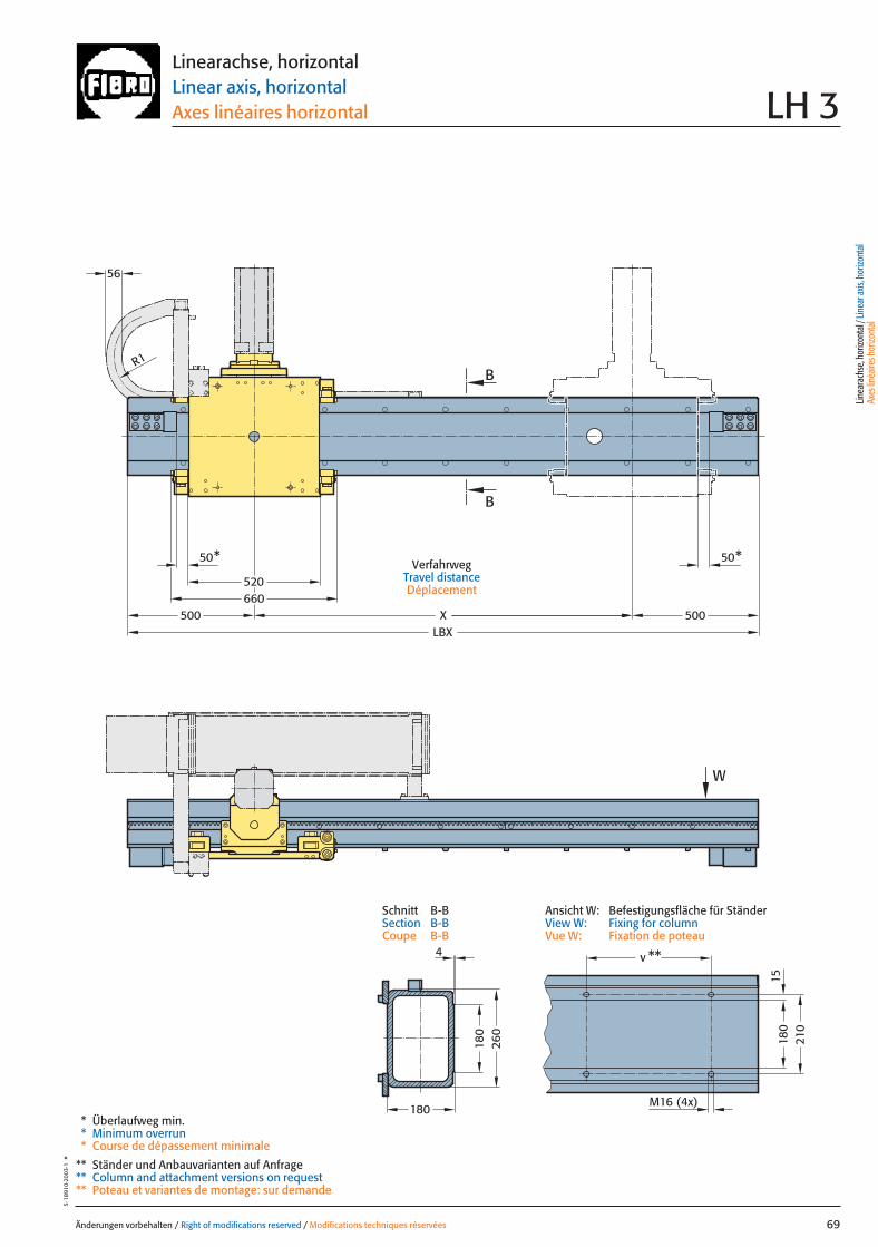
W
R1
500500LBX
520
X660
50*50*
56
B
B
180
210
180
260
180
v **
M16 (4x)
15
4
Änderungen vorbehalten / Right of modifications reserved / Modifications techniques réservées 69
5·18
910·
2003
·1°
Linearachse, horizontalLinear axis, horizontalAxes linéaires horizontal LH 3
VerfahrwegTravel distanceDéplacement
* Überlaufweg min.* Minimum overrun* Course de dépassement minimale
** Ständer und Anbauvarianten auf Anfrage** Column and attachment versions on request** Poteau et variantes de montage: sur demande
Linea
rach
se, h
orizo
ntal
/ Lin
ear a
xis, h
orizo
ntal
Axes
linéa
ires h
orizo
ntal
Ansicht W: Befestigungsfläche für StänderView W: Fixing for columnVue W: Fixation de poteau
Schnitt B-BSection B-BCoupe B-B
069 27.08.2004 6:03 Uhr Seite 1
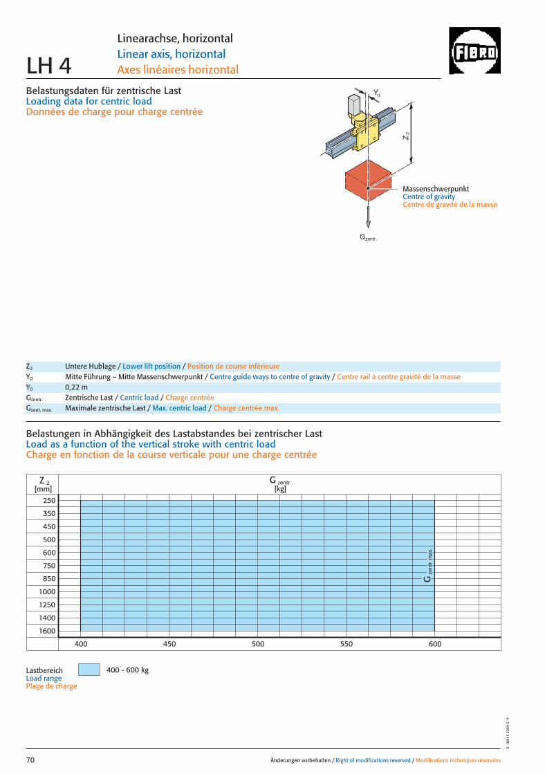
Belastungsdaten für zentrische LastLoading data for centric loadDonnées de charge pour charge centrée
MassenschwerpunktCentre of gravityCentre de gravité de la masse
Z2
0Y
zent
rG
max
.
G zentr[kg]
400 - 600 kg
2
250
350
450
500
600
750
850
1000
1250
1400
1600
Z[mm]
400 450 500 550 600
Änderungen vorbehalten / Right of modifications reserved / Modifications techniques réservées70
5·18
911·
2004
·2°
Linearachse, horizontalLinear axis, horizontalAxes linéaires horizontalLH 4
Z2 Untere Hublage / Lower lift position / Position de course inférieureY0 Mitte Führung – Mitte Massenschwerpunkt / Centre guide ways to centre of gravity / Centre rail à centre gravité de la masseY0 0,22 mGzentr. Zentrische Last / Centric load / Charge centréeGzent. max. Maximale zentrische Last / Max. centric load / Charge centrée max.
Belastungen in Abhängigkeit des Lastabstandes bei zentrischer Last Load as a function of the vertical stroke with centric loadCharge en fonction de la course verticale pour une charge centrée
LastbereichLoad rangePlage de charge
Gzentr.
070 27.08.2004 6:04 Uhr Seite 2
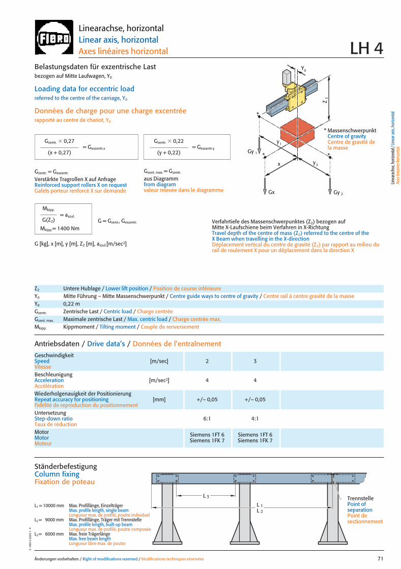
x
Gy 2
Gy 1
Gx
2y
1y
Z2
*
**
0Y
Änderungen vorbehalten / Right of modifications reserved / Modifications techniques réservées 71
5·18
912·
2003
·1°
Linearachse, horizontalLinear axis, horizontalAxes linéaires horizontal LH 4
Antriebsdaten / Drive data’s / Données de l’entraînement
GeschwindigkeitSpeed [m/sec] 2 3Vitesse
Wiederholgenauigkeit der PositionierungRepeat accuracy for positioning [mm] +/– 0,05 +/– 0,05Fidélité de reproduction du positionnement
BeschleunigungAcceleration [m/sec2] 4 4Accélération
Motor Siemens 1FT 6 Siemens 1FT 6Motor Siemens 1FK 7 Siemens 1FK 7Moteur
UntersetzungStep-down ratio 6:1 4:1Taux de réduction
= Gexzentr.y
Belastungsdaten für exzentrische Lastbezogen auf Mitte Laufwagen, Y0
Loading data for eccentric loadreferred to the centre of the carriage, Y0
Données de charge pour une charge excentréerapporté au centre de chariot, Y0
Verfahrtiefe des Massenschwerpunktes (Z2) bezogen auf Mitte X-Laufschiene beim Verfahren in X-RichtungTravel depth of the centre of mass (Z2) referred to the centre of the X Beam when travelling in the X-directionDéplacement vertical du centre de gravité (Z2) par rapport au milieu durail de roulement X pour un déplacement dans la direction X
G [kg], x [m], y [m], Z2 [m], axzul.[m/sec2]
= Gexzentr.x
Gzentr. � 0,27
(x + 0,27)
Gzentr. � 0,22
(y + 0,22)
Gzentr. = Gexzentr.
Verstärkte Tragrollen X auf AnfrageReinforced support rollers X on requestGalets porteur renforcé X sur demande
Gzent. max. = Gzentr.
aus Diagrammfrom diagramvaleur relevée dans le diagramme
* MassenschwerpunktCentre of gravityCentre de gravité dela masse
Z2 Untere Hublage / Lower lift position / Position de course inférieureY0 Mitte Führung – Mitte Massenschwerpunkt / Centre guide ways to centre of gravity / Centre rail à centre gravité de la masseY0 0,22 mGzentr. Zentrische Last / Centric load / Charge centréeGzent. max. Maximale zentrische Last / Max. centric load / Charge centrée max.Mkipp. Kippmoment / Tilting moment / Couple de renversement
= axzul.
Mkipp.
G(Z2)
Mkipp.= 1400 NmG = Gzent., Gexzentr.
L 3
L 1L 2
Ständerbefestigung Column fixingFixation de poteau
L1 = 10000 mm Max. Profillänge, EinzelträgerMax. profile length, single beam Longueur max. de profilé, poutre individuel
L2 = 9000 mm Max. Profillänge, Träger mit TrennstelleMax. profile length, built-up beam Longueur max. de profilé, poutre composée
L3 = 6000 mm Max. freie TrägerlängeMax. free beam length Longueur libre max. de poutre
TrennstellePoint of separationPoint de sectionnement
Linea
rach
se, h
orizo
ntal
/ Lin
ear a
xis, h
orizo
ntal
Axes
linéa
ires h
orizo
ntal
071 27.08.2004 6:04 Uhr Seite 1
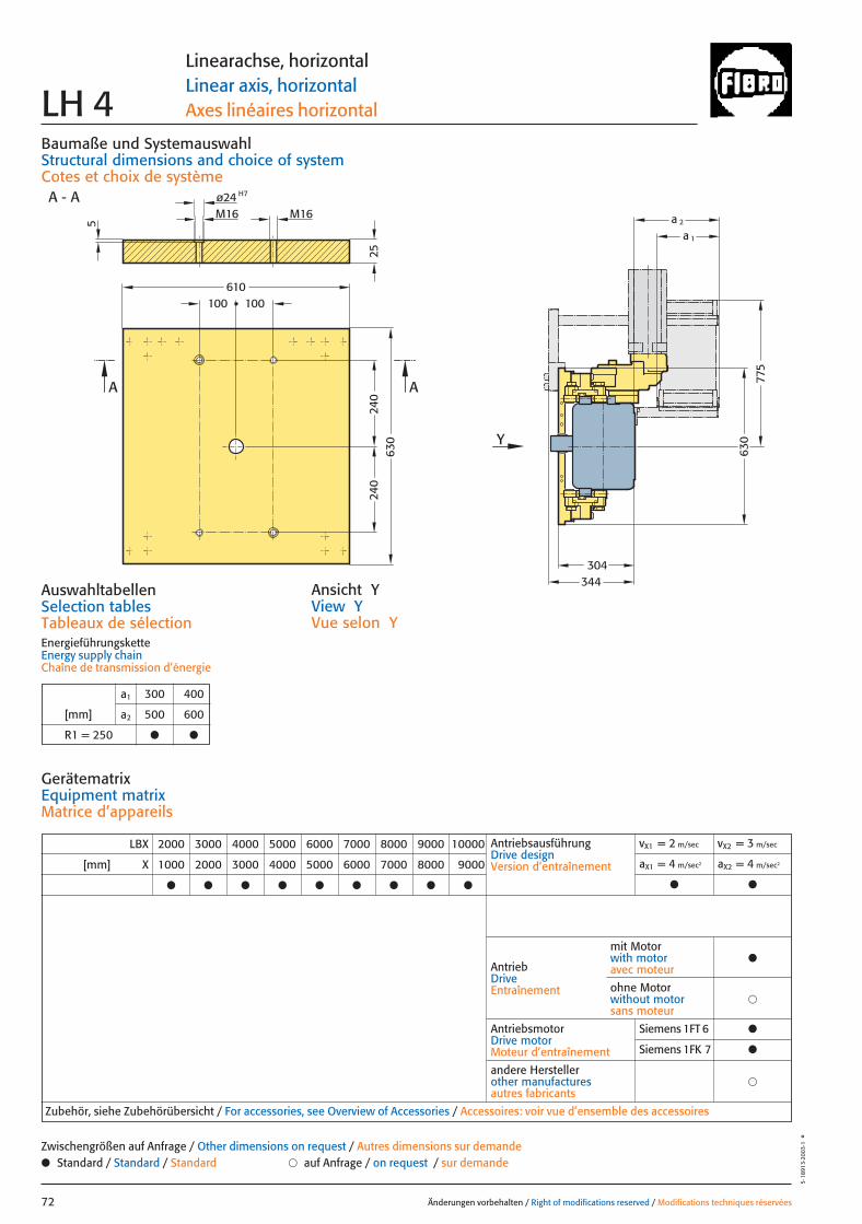
240
25
100100
240
630
630
775
344
Y
610
AA
A - A H7ø24M16 M16
5
a 1
a 2
304
Baumaße und SystemauswahlStructural dimensions and choice of systemCotes et choix de système
Änderungen vorbehalten / Right of modifications reserved / Modifications techniques réservées72
5·18
913·
2003
·1°
Linearachse, horizontalLinear axis, horizontalAxes linéaires horizontal LH 4
Ansicht YView YVue selon Y
AuswahltabellenSelection tablesTableaux de sélectionEnergieführungsketteEnergy supply chainChaîne de transmission d’énergie
a1 300 400
[mm] a2 500 600
R1 = 250 ● ●
LBX 2000 3000 4000 5000 6000 7000 8000 9000 10000
[mm] X 1000 2000 3000 4000 5000 6000 7000 8000 9000
● ● ● ● ● ● ● ● ●
AntriebsausführungDrive designVersion d’entraînement
vX1 = 2 m/sec vX2 = 3 m/sec
aX1 = 4 m/sec2 aX2 = 4 m/sec2
● ●
AntriebDriveEntraînement
AntriebsmotorDrive motorMoteur d’entraînement
�andere Herstellerother manufacturesautres fabricants
Zubehör, siehe Zubehörübersicht / For accessories, see Overview of Accessories / Accessoires: voir vue d’ensemble des accessoires
mit Motorwith motoravec moteur
●
�ohne Motorwithout motorsans moteur
GerätematrixEquipment matrixMatrice d’appareils
● Standard / Standard / Standard � auf Anfrage / on request / sur demandeZwischengrößen auf Anfrage / Other dimensions on request / Autres dimensions sur demande
Siemens 1FT 6 ●
Siemens 1FK 7 ●
072 27.08.2004 6:04 Uhr Seite 2
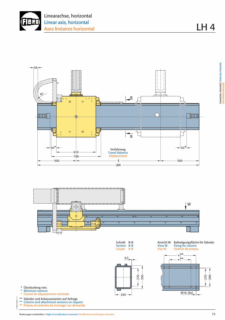
500500 XLBX
610748
50*50*
R1
W
56
B
B27
035
0
250
**2
M16 (8x)
270
290
v
1v **4,5
Änderungen vorbehalten / Right of modifications reserved / Modifications techniques réservées 73
5·18
914·
2003
·1°
Linearachse, horizontalLinear axis, horizontalAxes linéaires horizontal LH 4
VerfahrwegTravel distanceDéplacement
* Überlaufweg min.* Minimum overrun* Course de dépassement minimale
** Ständer und Anbauvarianten auf Anfrage** Column and attachment versions on request** Poteau et variantes de montage: sur demande
Linea
rach
se, h
orizo
ntal
/ Lin
ear a
xis, h
orizo
ntal
Axes
linéa
ires h
orizo
ntal
Ansicht W: Befestigungsfläche für StänderView W: Fixing for columnVue W: Fixation de poteau
Schnitt B-BSection B-BCoupe B-B
073 27.08.2004 6:04 Uhr Seite 1
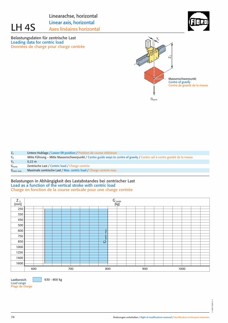
Belastungsdaten für zentrische LastLoading data for centric loadDonnées de charge pour charge centrée
MassenschwerpunktCentre of gravityCentre de gravité de la masse
Z2
0Y
zent
rG
max
.
G zentr[kg]
630 - 800 kg
2
250
350
450
500
600
750
850
1000
1250
1400
1600
Z[mm]
600 700 800 900 1000
Änderungen vorbehalten / Right of modifications reserved / Modifications techniques réservées74
5·18
915·
2004
·2°
Linearachse, horizontalLinear axis, horizontalAxes linéaires horizontalLH 4S
Z2 Untere Hublage / Lower lift position / Position de course inférieureY0 Mitte Führung – Mitte Massenschwerpunkt / Centre guide ways to centre of gravity / Centre rail à centre gravité de la masseY0 0,22 mGzentr. Zentrische Last / Centric load / Charge centréeGzent. max. Maximale zentrische Last / Max. centric load / Charge centrée max.
Belastungen in Abhängigkeit des Lastabstandes bei zentrischer LastLoad as a function of the vertical stroke with centric loadCharge en fonction de la course verticale pour une charge centrée
LastbereichLoad rangePlage de charge
Gzentr.
074 27.08.2004 6:04 Uhr Seite 2

x
Gy 2
Gy 1
Gx
2y
1y
Z2
*
**
0Y
Änderungen vorbehalten / Right of modifications reserved / Modifications techniques réservées 75
5·18
916·
2003
·1°
Linearachse, horizontalLinear axis, horizontalAxes linéaires horizontal LH 4S
Antriebsdaten / Drive data’s / Données de l’entraînement
GeschwindigkeitSpeed [m/sec] 2 3Vitesse
Wiederholgenauigkeit der PositionierungRepeat accuracy for positioning [mm] +/– 0,05 +/– 0,05Fidélité de reproduction du positionnement
BeschleunigungAcceleration [m/sec2] 4 5Accélération
Motor Siemens 1FT 6 Siemens 1FT 6Motor Siemens 1FK 7 Siemens 1FK 7Moteur
UntersetzungStep-down ratio 6:1 4:1Taux de réduction
= Gexzentr.y
Belastungsdaten für exzentrische Lastbezogen auf Mitte Laufwagen, Y0
Loading data for eccentric loadreferred to the centre of the carriage, Y0
Données de charge pour une charge excentréerapporté au centre de chariot, Y0
Verfahrtiefe des Massenschwerpunktes (Z2) bezogen auf Mitte X-Laufschiene beim Verfahren in X-RichtungTravel depth of the centre of mass (Z2) referred to the centre of the X Beam when travelling in the X-directionDéplacement vertical du centre de gravité (Z2) par rapport au milieu durail de roulement X pour un déplacement dans la direction X
G [kg], x [m], y [m], Z2 [m], axzul.[m/sec2]
= Gexzentr.x
Gzentr. � 0,27
(x + 0,27)
Gzentr. � 0,22
(y + 0,22)
Gzentr. = Gexzentr.
Verstärkte Tragrollen X auf AnfrageReinforced support rollers X on requestGalets porteur renforcé X sur demande
Gzent. max. = Gzentr.
aus Diagrammfrom diagramvaleur relevée dans le diagramme
* MassenschwerpunktCentre of gravityCentre de gravité dela masse
Z2 Untere Hublage / Lower lift position / Position de course inférieureY0 Mitte Führung – Mitte Massenschwerpunkt / Centre guide ways to centre of gravity / Centre rail à centre gravité de la masseY0 0,22 mGzentr. Zentrische Last / Centric load / Charge centréeGzent. max. Maximale zentrische Last / Max. centric load / Charge centrée max.Mkipp. Kippmoment / Tilting moment / Couple de renversement
= axzul.
Mkipp.
G(Z2)
Mkipp.= 2800 NmG = Gzent., Gexzentr.
L 3
L 1L 2
Ständerbefestigung Column fixingFixation de poteau
L1 = 10000 mm Max. Profillänge, EinzelträgerMax. profile length, single beam Longueur max. de profilé, poutre individuel
L2 = 9000 mm Max. Profillänge, Träger mit TrennstelleMax. profile length, built-up beam Longueur max. de profilé, poutre composée
L3 = 6000 mm Max. freie TrägerlängeMax. free beam length Longueur libre max. de poutre
TrennstellePoint of separationPoint de sectionnement
Linea
rach
se, h
orizo
ntal
/ Lin
ear a
xis, h
orizo
ntal
Axes
linéa
ires h
orizo
ntal
075 27.08.2004 6:05 Uhr Seite 1
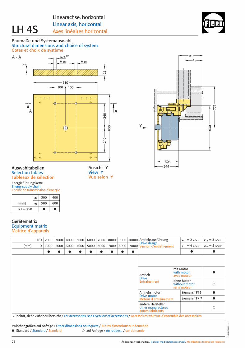
240
240
630
775
344
a 1
a 2
Y
304
25
100100
630
610
AA
A - A H7ø24M16 M16
5
Baumaße und SystemauswahlStructural dimensions and choice of systemCotes et choix de système
Änderungen vorbehalten / Right of modifications reserved / Modifications techniques réservées76
5·18
917·
2003
·1°
Linearachse, horizontalLinear axis, horizontalAxes linéaires horizontal LH 4S
Ansicht YView YVue selon Y
AuswahltabellenSelection tablesTableaux de sélectionEnergieführungsketteEnergy supply chainChaîne de transmission d’énergie
a1 300 400
[mm] a2 500 600
R1 = 250 ● ●
LBX 2000 3000 4000 5000 6000 7000 8000 9000 10000
[mm] X 1000 2000 3000 4000 5000 6000 7000 8000 9000
● ● ● ● ● ● ● ● ●
AntriebsausführungDrive designVersion d’entraînement
vX1 = 2 m/sec vX2 = 3 m/sec
aX1 = 4 m/sec2 aX2 = 5 m/sec2
● ●
AntriebDriveEntraînement
AntriebsmotorDrive motorMoteur d’entraînement
�andere Herstellerother manufacturesautres fabricants
Zubehör, siehe Zubehörübersicht / For accessories, see Overview of Accessories / Accessoires: voir vue d’ensemble des accessoires
mit Motorwith motoravec moteur
●
�ohne Motorwithout motorsans moteur
GerätematrixEquipment matrixMatrice d’appareils
● Standard / Standard / Standard � auf Anfrage / on request / sur demandeZwischengrößen auf Anfrage / Other dimensions on request / Autres dimensions sur demande
Siemens 1FT 6 ●
Siemens 1FK 7 ●
076 27.08.2004 6:03 Uhr Seite 2
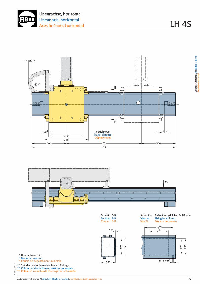
500 XLBX
610748
50*50*
R1
W
500
56
B
B27
035
0
250
**2
M16 (8x)
270
290
v
1v **4,5
Änderungen vorbehalten / Right of modifications reserved / Modifications techniques réservées 77
5·18
918·
2003
·1°
Linearachse, horizontalLinear axis, horizontalAxes linéaires horizontal LH 4S
VerfahrwegTravel distanceDéplacement
* Überlaufweg min.* Minimum overrun* Course de dépassement minimale
** Ständer und Anbauvarianten auf Anfrage** Column and attachment versions on request** Poteau et variantes de montage: sur demande
Linea
rach
se, h
orizo
ntal
/ Lin
ear a
xis, h
orizo
ntal
Axes
linéa
ires h
orizo
ntal
Ansicht W: Befestigungsfläche für StänderView W: Fixing for columnVue W: Fixation de poteau
Schnitt B-BSection B-BCoupe B-B
077 27.08.2004 6:04 Uhr Seite 1
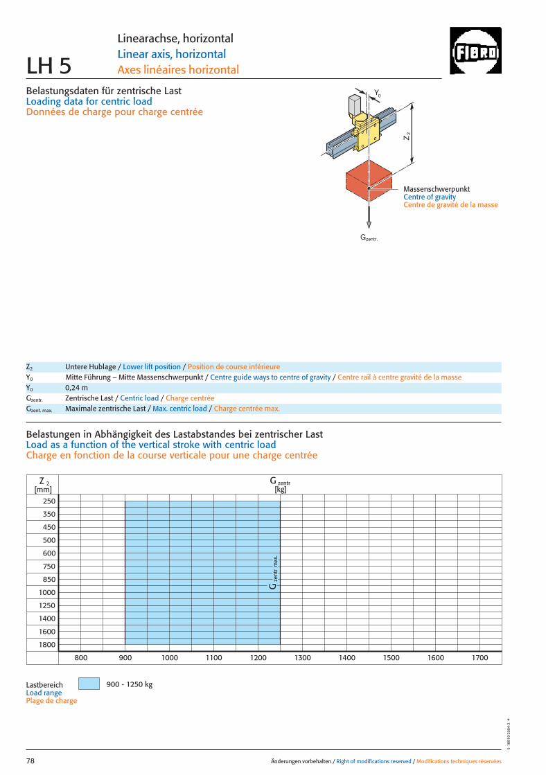
Belastungsdaten für zentrische LastLoading data for centric loadDonnées de charge pour charge centrée
MassenschwerpunktCentre of gravityCentre de gravité de la masse
Z2
0Y
zent
rG
max
.
G zentr[kg]
900 - 1250 kg
2
250
350
450
500
600
750
850
1000
1250
1400
1600
Z[mm]
800 1000900 1100 1200 1300 1400 1500 1600
1800
1700
Änderungen vorbehalten / Right of modifications reserved / Modifications techniques réservées78
5·18
919·
2004
·2°
Linearachse, horizontalLinear axis, horizontalAxes linéaires horizontalLH 5
Z2 Untere Hublage / Lower lift position / Position de course inférieureY0 Mitte Führung – Mitte Massenschwerpunkt / Centre guide ways to centre of gravity / Centre rail à centre gravité de la masseY0 0,24 mGzentr. Zentrische Last / Centric load / Charge centréeGzent. max. Maximale zentrische Last / Max. centric load / Charge centrée max.
Belastungen in Abhängigkeit des Lastabstandes bei zentrischer Last Load as a function of the vertical stroke with centric loadCharge en fonction de la course verticale pour une charge centrée
LastbereichLoad rangePlage de charge
Gzentr.
078 27.08.2004 6:04 Uhr Seite 2

x
Gy 2
Gy 1
Gx
2y
1y
Z2
*
**
0Y
Änderungen vorbehalten / Right of modifications reserved / Modifications techniques réservées 79
5·18
920·
2003
·1°
Linearachse, horizontalLinear axis, horizontalAxes linéaires horizontal LH 5
Antriebsdaten / Drive data’s / Données de l’entraînement
GeschwindigkeitSpeed [m/sec] 2 3Vitesse
Wiederholgenauigkeit der PositionierungRepeat accuracy for positioning [mm] +/– 0,05 +/– 0,05Fidélité de reproduction du positionnement
BeschleunigungAcceleration [m/sec2] 4 4Accélération
Motor Siemens 1FT 6 Siemens 1FT 6Motor Siemens 1FK 7 Siemens 1FK 7Moteur
UntersetzungStep-down ratio 6:1 4:1Taux de réduction
= Gexzentr.y
Belastungsdaten für exzentrische Lastbezogen auf Mitte Laufwagen, Y0
Loading data for eccentric loadreferred to the centre of the carriage, Y0
Données de charge pour une charge excentréerapporté au centre de chariot, Y0
Verfahrtiefe des Massenschwerpunktes (Z2) bezogen auf Mitte X-Laufschiene beim Verfahren in X-RichtungTravel depth of the centre of mass (Z2) referred to the centre of the X Beam when travelling in the X-directionDéplacement vertical du centre de gravité (Z2) par rapport au milieu durail de roulement X pour un déplacement dans la direction X
G [kg], x [m], y [m], Z2 [m], axzul.[m/sec2]
= Gexzentr.x
Gzentr. � 0,324
(x + 0,324)
Gzentr. � 0,24
(y + 0,24)
Gzentr. = Gexzentr.
Verstärkte Tragrollen X auf AnfrageReinforced support rollers X on requestGalets porteur renforcé X sur demande
Gzent. max. = Gzentr.
aus Diagrammfrom diagramvaleur relevée dans le diagramme
* MassenschwerpunktCentre of gravityCentre de gravité dela masse
Z2 Untere Hublage / Lower lift position / Position de course inférieureY0 Mitte Führung – Mitte Massenschwerpunkt / Centre guide ways to centre of gravity / Centre rail à centre gravité de la masseY0 0,24 mGzentr. Zentrische Last / Centric load / Charge centréeGzent. max. Maximale zentrische Last / Max. centric load / Charge centrée max.Mkipp. Kippmoment / Tilting moment / Couple de renversement
= axzul.
Mkipp.
G(Z2)
Mkipp.= 3600 NmG = Gzent., Gexzentr.
L 3
L 1L 2
Ständerbefestigung Column fixingFixation de poteau
L1 = 10000 mm Max. Profillänge, EinzelträgerMax. profile length, single beam Longueur max. de profilé, poutre individuel
L2 = 9000 mm Max. Profillänge, Träger mit TrennstelleMax. profile length, built-up beam Longueur max. de profilé, poutre composée
L3 = 6000 mm Max. freie TrägerlängeMax. free beam length Longueur libre max. de poutre
TrennstellePoint of separationPoint de sectionnement
Linea
rach
se, h
orizo
ntal
/ Lin
ear a
xis, h
orizo
ntal
Axes
linéa
ires h
orizo
ntal
079 27.08.2004 6:05 Uhr Seite 1

27
680
800
394
250
250
135
680
730
AA
A - A
M20
H7ø28M20
5,5
Y
135
a 1
a 2
354
Baumaße und SystemauswahlStructural dimensions and choice of systemCotes et choix de système
Auswahltabellen / Selection tablesTableaux de sélectionEnergieführungskette / Energy supply chainChaîne de transmission d’énergie
Änderungen vorbehalten / Right of modifications reserved / Modifications techniques réservées80
5·18
921·
2003
·1°
Linearachse, horizontalLinear axis, horizontalAxes linéaires horizontal LH 5
Ansicht YView YVue selon Y
LBX 2000 3000 4000 5000 6000 7000 8000 9000 10000
[mm] X 800 1800 2800 3800 4800 5800 6800 7800 8800
● ● ● ● ● ● ● ● ●
AntriebsausführungDrive designVersion d’entraînement
vX1 = 2 m/sec vX2 = 3 m/sec
aX1 = 4 m/sec2 aX2 = 4 m/sec2
● ●
AntriebDriveEntraînement
AntriebsmotorDrive motorMoteur d’entraînement
�andere Herstellerother manufacturesautres fabricants
Zubehör, siehe Zubehörübersicht / For accessories, see Overview of Accessories / Accessoires: voir vue d’ensemble des accessoires
mit Motorwith motoravec moteur
●
�ohne Motorwithout motorsans moteur
GerätematrixEquipment matrixMatrice d’appareils
● Standard / Standard / Standard � auf Anfrage / on request / sur demandeZwischengrößen auf Anfrage / Other dimensions on request / Autres dimensions sur demande
a1 300 400
[mm] a2 500 600
R1 = 250 ● ●
Siemens 1FT 6 ●
Siemens 1FK 7 ●
080 27.08.2004 6:04 Uhr Seite 2
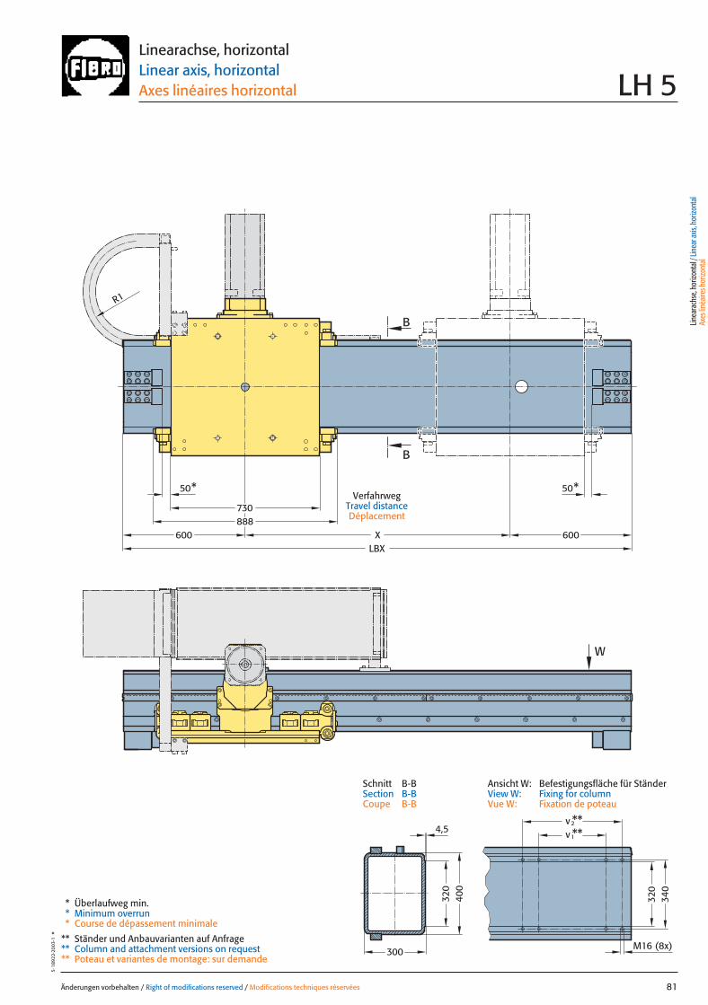
600 600
W
XLBX
50* 50*
R1
730888
B
B
300
320
400
**v **
M16 (8x)
340
320
2
1v4,5
Änderungen vorbehalten / Right of modifications reserved / Modifications techniques réservées 81
5·18
922·
2003
·1°
Linearachse, horizontalLinear axis, horizontalAxes linéaires horizontal LH 5
VerfahrwegTravel distanceDéplacement
* Überlaufweg min.* Minimum overrun* Course de dépassement minimale
** Ständer und Anbauvarianten auf Anfrage** Column and attachment versions on request** Poteau et variantes de montage: sur demande
Linea
rach
se, h
orizo
ntal
/ Lin
ear a
xis, h
orizo
ntal
Axes
linéa
ires h
orizo
ntal
Ansicht W: Befestigungsfläche für StänderView W: Fixing for columnVue W: Fixation de poteau
Schnitt B-BSection B-BCoupe B-B
081 27.08.2004 6:04 Uhr Seite 1
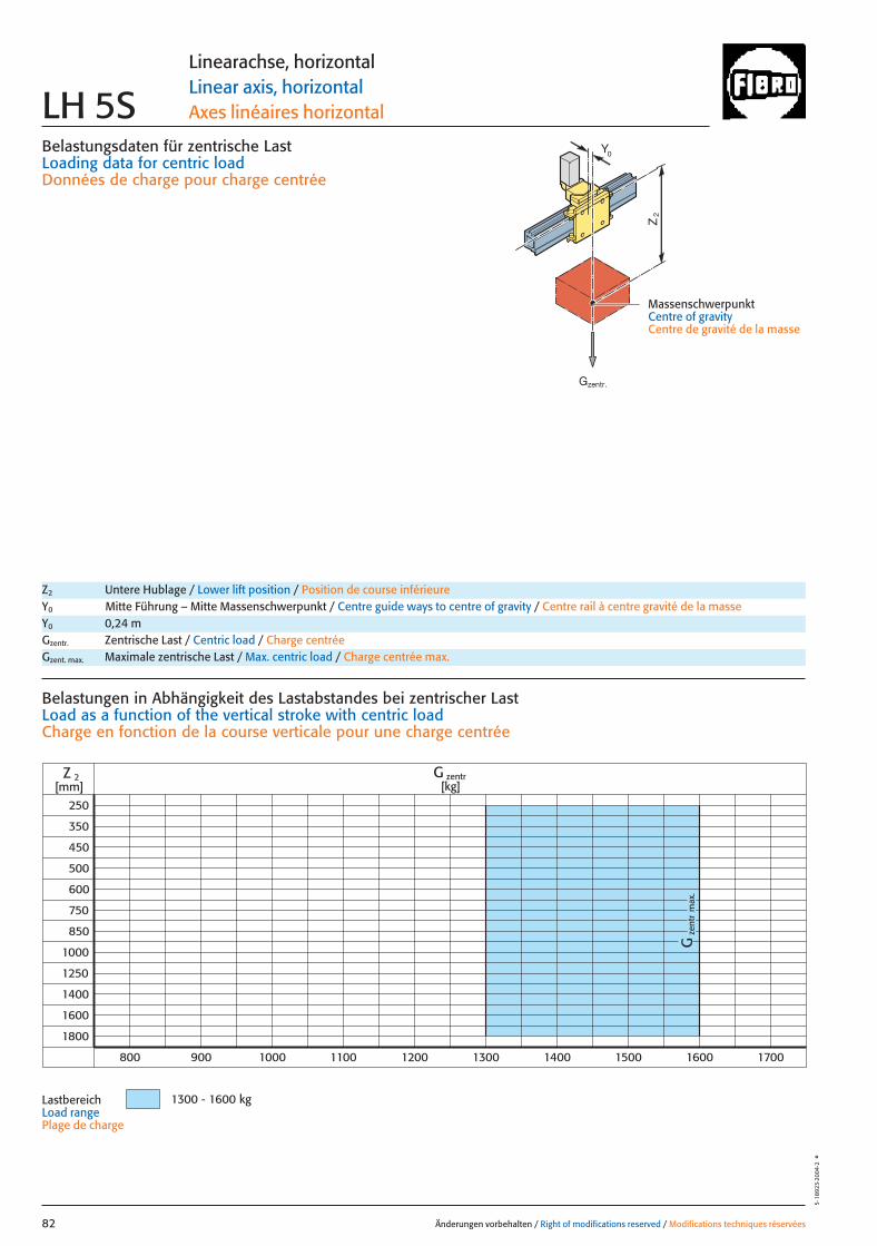
Belastungsdaten für zentrische LastLoading data for centric loadDonnées de charge pour charge centrée
MassenschwerpunktCentre of gravityCentre de gravité de la masse
Z2
0Y
zent
rG
max
.
G zentr[kg]
1300 - 1600 kg
2
250
350
450
500
600
750
850
1000
1250
1400
1600
Z[mm]
800 1000900 1100 1200 1300 1400 1500 1600
1800
1700
Änderungen vorbehalten / Right of modifications reserved / Modifications techniques réservées82
5·18
923·
2004
·2°
Linearachse, horizontalLinear axis, horizontalAxes linéaires horizontalLH 5S
Z2 Untere Hublage / Lower lift position / Position de course inférieureY0 Mitte Führung – Mitte Massenschwerpunkt / Centre guide ways to centre of gravity / Centre rail à centre gravité de la masseY0 0,24 mGzentr. Zentrische Last / Centric load / Charge centréeGzent. max. Maximale zentrische Last / Max. centric load / Charge centrée max.
Belastungen in Abhängigkeit des Lastabstandes bei zentrischer Last Load as a function of the vertical stroke with centric loadCharge en fonction de la course verticale pour une charge centrée
LastbereichLoad rangePlage de charge
Gzentr.
082 27.08.2004 6:05 Uhr Seite 2
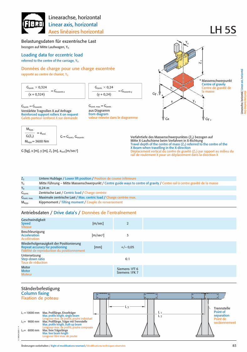
x
Gy 2
Gy 1
Gx
2y
1y
Z2
*
**
0Y
Änderungen vorbehalten / Right of modifications reserved / Modifications techniques réservées 83
5·18
924·
2003
·1°
Linearachse, horizontalLinear axis, horizontalAxes linéaires horizontal LH 5S
Antriebsdaten / Drive data’s / Données de l’entraînement
GeschwindigkeitSpeed [m/sec] 2Vitesse
Wiederholgenauigkeit der PositionierungRepeat accuracy for positioning [mm] +/– 0,05Fidélité de reproduction du positionnement
BeschleunigungAcceleration [m/sec2] 3Accélération
Motor Siemens 1FT 6Motor Siemens 1FK 7Moteur
UntersetzungStep-down ratio 6:1Taux de réduction
= Gexzentr.y
Belastungsdaten für exzentrische Lastbezogen auf Mitte Laufwagen, Y0
Loading data for eccentric loadreferred to the centre of the carriage, Y0
Données de charge pour une charge excentréerapporté au centre de chariot, Y0
Verfahrtiefe des Massenschwerpunktes (Z2) bezogen auf Mitte X-Laufschiene beim Verfahren in X-RichtungTravel depth of the centre of mass (Z2) referred to the centre of the X Beam when travelling in the X-directionDéplacement vertical du centre de gravité (Z2) par rapport au milieu durail de roulement X pour un déplacement dans la direction X
G [kg], x [m], y [m], Z2 [m], axzul.[m/sec2]
= Gexzentr.x
Gzentr. � 0,324
(x + 0,324)
Gzentr. � 0,24
(y + 0,24)
Gzentr. = Gexzentr.
Verstärkte Tragrollen X auf AnfrageReinforced support rollers X on requestGalets porteur renforcé X sur demande
Gzent. max. = Gzentr.
aus Diagrammfrom diagramvaleur relevée dans le diagramme
* MassenschwerpunktCentre of gravityCentre de gravité dela masse
Z2 Untere Hublage / Lower lift position / Position de course inférieureY0 Mitte Führung – Mitte Massenschwerpunkt / Centre guide ways to centre of gravity / Centre rail à centre gravité de la masseY0 0,24 mGzentr. Zentrische Last / Centric load / Charge centréeGzent. max. Maximale zentrische Last / Max. centric load / Charge centrée max.Mkipp. Kippmoment / Tilting moment / Couple de renversement
= axzul.
Mkipp.
G(Z2)
Mkipp.= 3600 NmG = Gzent., Gexzentr.
L 3
L 1L 2
Ständerbefestigung Column fixingFixation de poteau
L1 = 10000 mm Max. Profillänge, EinzelträgerMax. profile length, single beam Longueur max. de profilé, poutre individuel
L2 = 9000 mm Max. Profillänge, Träger mit TrennstelleMax. profile length, built-up beam Longueur max. de profilé, poutre composée
L3 = 6000 mm Max. freie TrägerlängeMax. free beam length Longueur libre max. de poutre
TrennstellePoint of separationPoint de sectionnement
Linea
rach
se, h
orizo
ntal
/ Lin
ear a
xis, h
orizo
ntal
Axes
linéa
ires h
orizo
ntal
083 27.08.2004 6:05 Uhr Seite 1
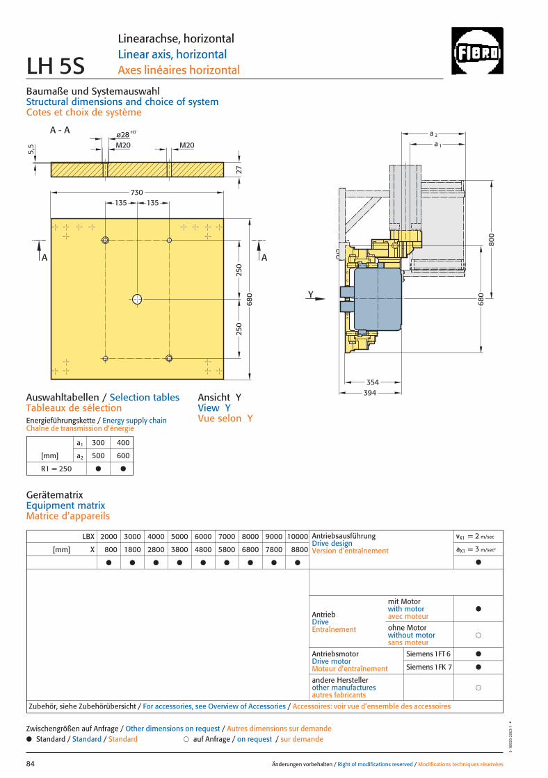
27
680
800
394
a 1
a 2
Y
250
250
135
680
730
AA
A - A
M20
H7ø28M20
5,5
135
354
Baumaße und SystemauswahlStructural dimensions and choice of systemCotes et choix de système
Auswahltabellen / Selection tablesTableaux de sélectionEnergieführungskette / Energy supply chainChaîne de transmission d’énergie
Änderungen vorbehalten / Right of modifications reserved / Modifications techniques réservées84
5·18
925·
2003
·1°
Linearachse, horizontalLinear axis, horizontalAxes linéaires horizontal LH 5S
Ansicht YView YVue selon Y
a1 300 400
[mm] a2 500 600
R1 = 250 ● ●
LBX 2000 3000 4000 5000 6000 7000 8000 9000 10000
[mm] X 800 1800 2800 3800 4800 5800 6800 7800 8800
● ● ● ● ● ● ● ● ●
AntriebsausführungDrive designVersion d’entraînement
vX1 = 2 m/sec
aX1 = 3 m/sec2
●
AntriebDriveEntraînement
AntriebsmotorDrive motorMoteur d’entraînement
�andere Herstellerother manufacturesautres fabricants
Zubehör, siehe Zubehörübersicht / For accessories, see Overview of Accessories / Accessoires: voir vue d’ensemble des accessoires
mit Motorwith motoravec moteur
●
�ohne Motorwithout motorsans moteur
GerätematrixEquipment matrixMatrice d’appareils
● Standard / Standard / Standard � auf Anfrage / on request / sur demandeZwischengrößen auf Anfrage / Other dimensions on request / Autres dimensions sur demande
Siemens 1FT 6 ●
Siemens 1FK 7 ●
084 27.08.2004 6:05 Uhr Seite 2
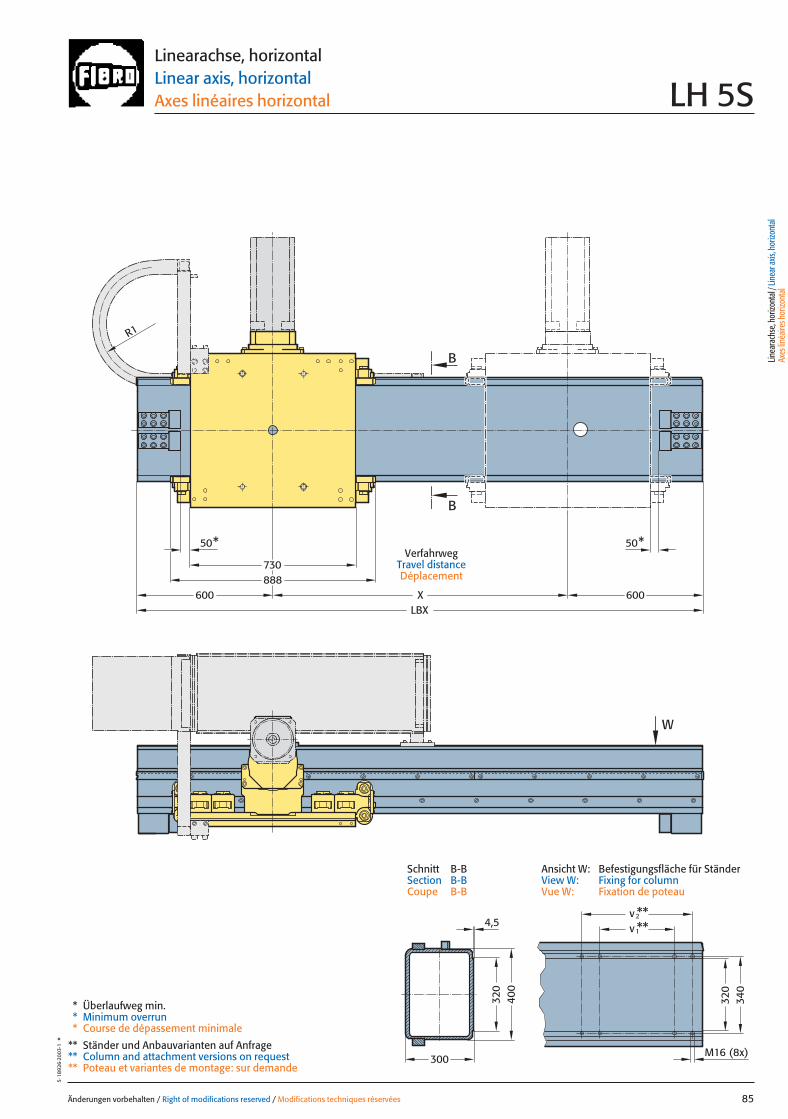
W
XLBX
50* 50*
R1
600 600
730888
B
B
300
320
400
**v **
M16 (8x)
340
320
2
1v4,5
Änderungen vorbehalten / Right of modifications reserved / Modifications techniques réservées 85
5·18
926·
2003
·1°
Linearachse, horizontalLinear axis, horizontalAxes linéaires horizontal LH 5S
VerfahrwegTravel distanceDéplacement
* Überlaufweg min.* Minimum overrun* Course de dépassement minimale
** Ständer und Anbauvarianten auf Anfrage** Column and attachment versions on request** Poteau et variantes de montage: sur demande
Linea
rach
se, h
orizo
ntal
/ Lin
ear a
xis, h
orizo
ntal
Axes
linéa
ires h
orizo
ntal
Ansicht W: Befestigungsfläche für StänderView W: Fixing for columnVue W: Fixation de poteau
Schnitt B-BSection B-BCoupe B-B
085 27.08.2004 6:05 Uhr Seite 1

Änderungen vorbehalten / Right of modifications reserved / Modifications techniques réservées86
5·18
927·
2003
·1°
086 27.08.2004 6:05 Uhr Seite 2
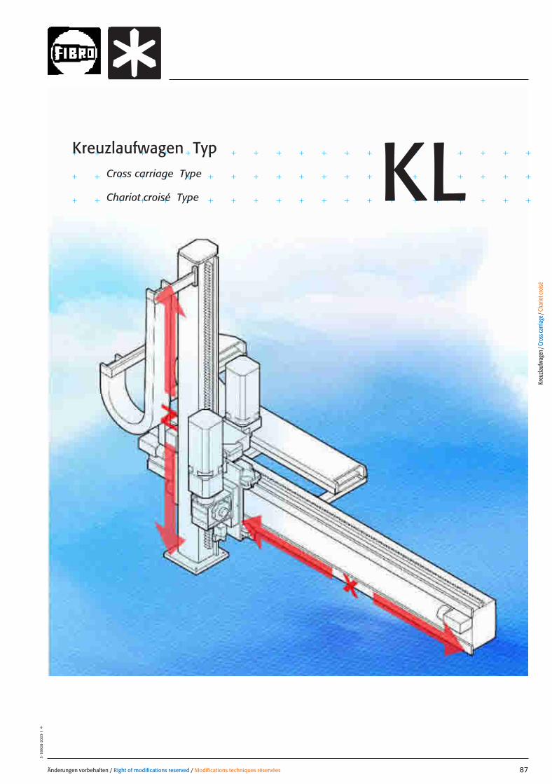
Änderungen vorbehalten / Right of modifications reserved / Modifications techniques réservées 87
5·18
928
·200
3·1
°
Kreuzlaufwagen TypCross carriage Type
Chariot croisé Type KL
Kreu
zlauf
wage
n / C
ross
carri
age /
Cha
riot c
roisé
087 27.08.2004 6:40 Uhr Seite 1
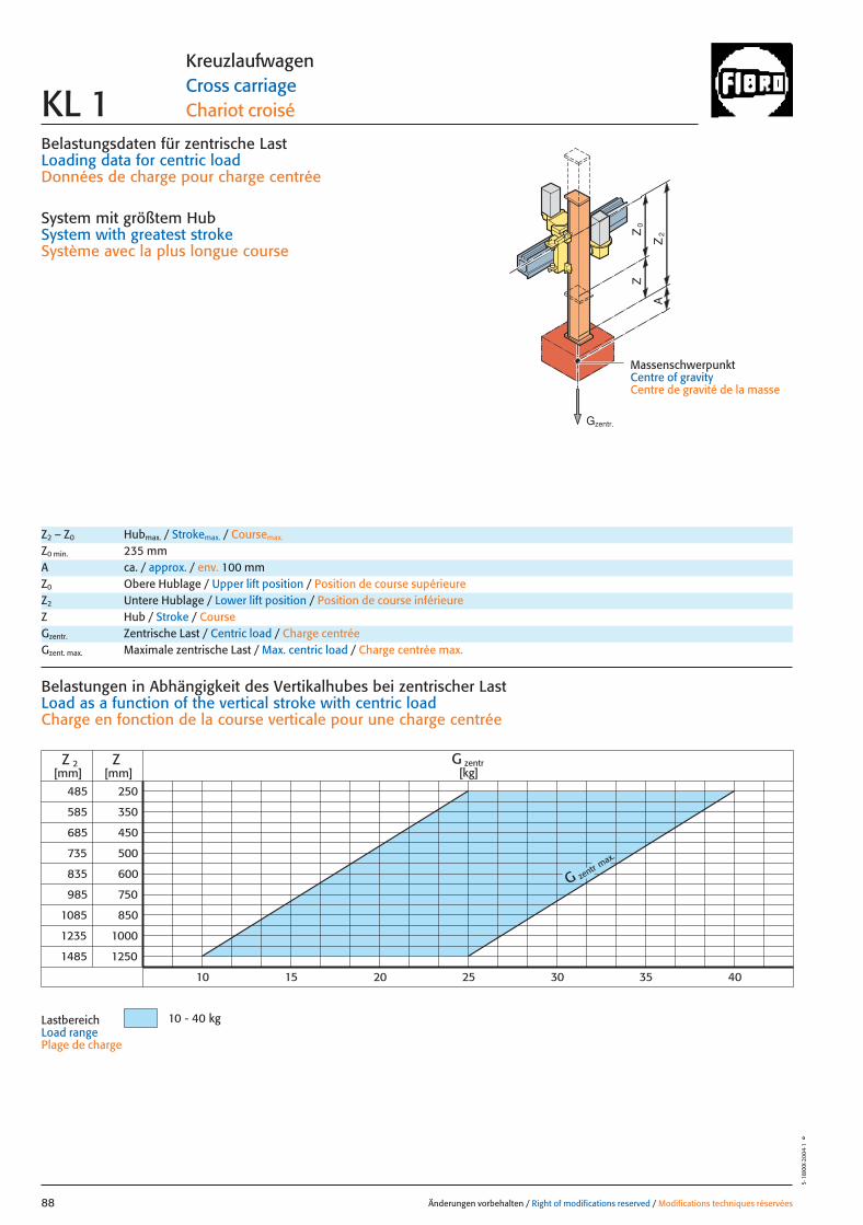
Belastungsdaten für zentrische LastLoading data for centric loadDonnées de charge pour charge centrée
System mit größtem HubSystem with greatest strokeSystème avec la plus longue course
MassenschwerpunktCentre of gravityCentre de gravité de la masse
0Z
Z
2Z
A
G zentr max.
485
585
985
1085
1235
1485
250
350
450
500
600
1000
1250
Z
10
Z 2[mm] [mm]
750
850
685
735
835
10 - 40 kg
G zentr[kg]
15 20 25 30 35 40
Änderungen vorbehalten / Right of modifications reserved / Modifications techniques réservées88
5·18
XXX·
2004
·1°
KreuzlaufwagenCross carriageChariot croiséKL 1
Z2 – Z0 Hubmax. / Strokemax. / Coursemax.
Z0 min. 235 mmA ca. / approx. / env. 100 mmZ0 Obere Hublage / Upper lift position / Position de course supérieureZ2 Untere Hublage / Lower lift position / Position de course inférieureZ Hub / Stroke / CourseGzentr. Zentrische Last / Centric load / Charge centréeGzent. max. Maximale zentrische Last / Max. centric load / Charge centrée max.
Belastungen in Abhängigkeit des Vertikalhubes bei zentrischer Last Load as a function of the vertical stroke with centric loadCharge en fonction de la course verticale pour une charge centrée
LastbereichLoad range Plage de charge
Gzentr.
088 27.08.2004 6:40 Uhr Seite 2
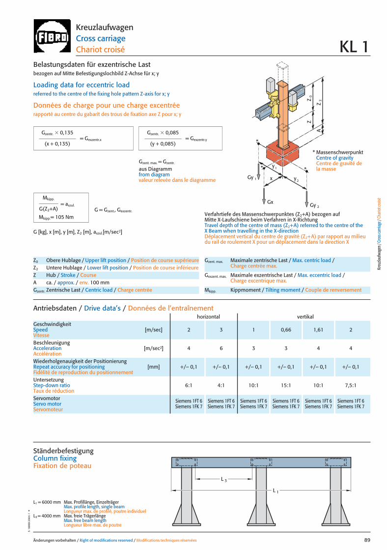
x
0Z
Z
2Z
A
Gy 2
Gy 1
Gx
2y
1y*
*
*
Änderungen vorbehalten / Right of modifications reserved / Modifications techniques réservées 89
5·18
XXX·
2004
·1°
KreuzlaufwagenCross carriageChariot croisé KL 1
Z0 Obere Hublage / Upper lift position / Position de course supérieureZ2 Untere Hublage / Lower lift position / Position de course inférieureZ Hub / Stroke / CourseA ca. / approx. / env. 100 mmGzentr. Zentrische Last / Centric load / Charge centrée
Gzent. max. Maximale zentrische Last / Max. centric load / Charge centrée max.
Gexzent. max. Maximale exzentrische Last / Max. eccentric load / Charge excentrique max.
Mkipp. Kippmoment / Tilting moment / Couple de renversement
Antriebsdaten / Drive data’s / Données de l’entraînement
GeschwindigkeitSpeed [m/sec] 2 3 1 0,66 1,61 2Vitesse
horizontal vertikal
Wiederholgenauigkeit der PositionierungRepeat accuracy for positioning [mm] +/– 0,1 +/– 0,1 +/– 0,1 +/– 0,1 +/– 0,1 +/– 0,1Fidélité de reproduction du positionnement
BeschleunigungAcceleration [m/sec2] 4 6 3 3 4 4Accélération
Servomotor Siemens 1FT 6 Siemens 1FT 6 Siemens 1FT 6 Siemens 1FT 6 Siemens 1FT 6 Siemens 1FT 6Servo motor Siemens 1FK 7 Siemens 1FK 7 Siemens 1FK 7 Siemens 1FK 7 Siemens 1FK 7 Siemens 1FK 7Servomoteur
UntersetzungStep-down ratio 6:1 4:1 10:1 15:1 10:1 7,5:1Taux de réduction
= Gexzentr.y
Belastungsdaten für exzentrische Lastbezogen auf Mitte Befestigungslochbild Z-Achse für x; y
Loading data for eccentric loadreferred to the centre of the fixing hole pattern Z-axis for x; y
Données de charge pour une charge excentréerapporté au centre du gabarit des trous de fixation axe Z pour x; y
Verfahrtiefe des Massenschwerpunktes (Z2+A) bezogen auf Mitte X-Laufschiene beim Verfahren in X-RichtungTravel depth of the centre of mass (Z2+A) referred to the centre of the X Beam when travelling in the X-directionDéplacement vertical du centre de gravité (Z2+A) par rapport au milieudu rail de roulement X pour un déplacement dans la direction X
G [kg], x [m], y [m], Z2 [m], axzul.[m/sec2]
= Gexzentr.x
Gzentr. � 0,135
(x + 0,135)
Gzentr. � 0,085
(y + 0,085)
Gzent. max. = Gzentr.
aus Diagrammfrom diagramvaleur relevée dans le diagramme
* MassenschwerpunktCentre of gravityCentre de gravité dela masse
= axzul.
Mkipp.
G(Z2+A)
Mkipp.= 105 NmG = Gzent., Gexzentr.
L 3
L 1
Ständerbefestigung Column fixingFixation de poteau
L1 = 6000 mm Max. Profillänge, EinzelträgerMax. profile length, single beam Longueur max. de profilé, poutre individuel
L3 = 4000 mm Max. freie TrägerlängeMax. free beam length Longueur libre max. de poutre
Kreu
zlauf
wage
n / C
ross
carri
age /
Cha
riot c
roisé
089 27.08.2004 6:43 Uhr Seite 1
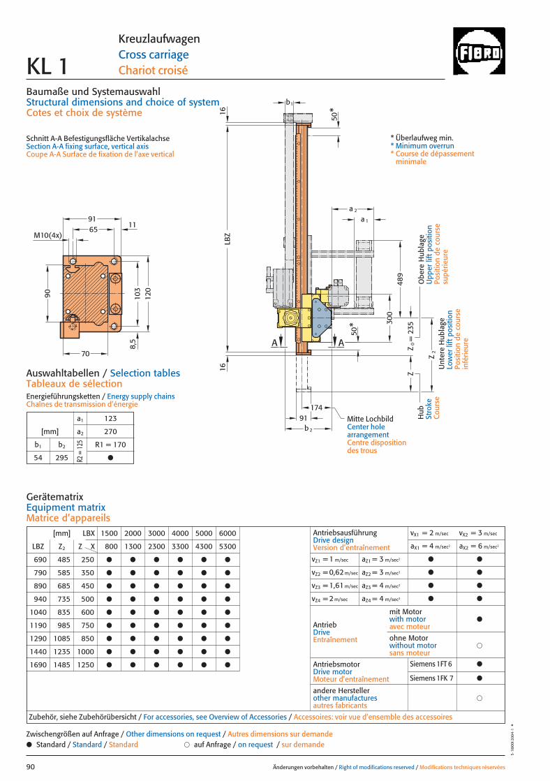
235
50
b1
b2
174Z
Z0=
Z2
a 1
a 2
1616
LBZ
50*
91
AA*
M10(4x)65
103
91
120
11
8,5
70
90
300
489
Baumaße und SystemauswahlStructural dimensions and choice of systemCotes et choix de système
Schnitt A-A Befestigungsfläche VertikalachseSection A-A fixing surface, vertical axisCoupe A-A Surface de fixation de l’axe vertical
Auswahltabellen / Selection tablesTableaux de sélectionEnergieführungsketten / Energy supply chainsChaînes de transmission d’énergie
Änderungen vorbehalten / Right of modifications reserved / Modifications techniques réservées90
5·18
XXX·
2004
·1°
KreuzlaufwagenCross carriageChariot croiséKL 1
Hub
Stro
keC
ours
e
Obe
re H
ubla
geU
pper
lift
pos
ition
Posi
tion
de c
ours
esu
périe
ure
Unt
ere
Hub
lage
Low
er li
ft p
ositi
onPo
sitio
n de
cou
rse
infé
rieur
e
* Überlaufweg min.* Minimum overrun* Course de dépassement
minimale
[mm] LBX 1500 2000 3000 4000 5000 6000
LBZ Z2 Z X 800 1300 2300 3300 4300 5300
690 485 250 ● ● ● ● ● ●
790 585 350 ● ● ● ● ● ●
890 685 450 ● ● ● ● ● ●
940 735 500 ● ● ● ● ● ●
1040 835 600 ● ● ● ● ● ●
1190 985 750 ● ● ● ● ● ●
1290 1085 850 ● ● ● ● ● ●
1440 1235 1000 ● ● ● ● ● ●
1690 1485 1250 ● ● ● ● ● ●
AntriebsausführungDrive designVersion d’entraînement
vX1 = 2 m/sec vX2 = 3 m/sec
aX1 = 4 m/sec2 aX2 = 6 m/sec2
vZ1 = 1 m/sec aZ1 = 3 m/sec2 ● ●
vZ2 = 0,62 m/sec aZ2 = 3 m/sec2 ● ●
vZ3 = 1,61 m/sec aZ3 = 4 m/sec2 ● ●
vZ4 = 2 m/sec aZ4 = 4 m/sec2 ● ●
AntriebDriveEntraînement
AntriebsmotorDrive motorMoteur d’entraînement
�andere Herstellerother manufacturesautres fabricants
Zubehör, siehe Zubehörübersicht / For accessories, see Overview of Accessories / Accessoires: voir vue d’ensemble des accessoires
mit Motorwith motoravec moteur
●
�ohne Motorwithout motorsans moteur
GerätematrixEquipment matrixMatrice d’appareils
a1 123
[mm] a2 270
b1 b2 R1 = 170
54 295 ●
● Standard / Standard / Standard � auf Anfrage / on request / sur demandeZwischengrößen auf Anfrage / Other dimensions on request / Autres dimensions sur demande
R2 =
125
Mitte LochbildCenter hole arrangementCentre disposition des trous
Siemens 1FT 6 ●
Siemens 1FK 7 ●
090 27.08.2004 6:43 Uhr Seite 2
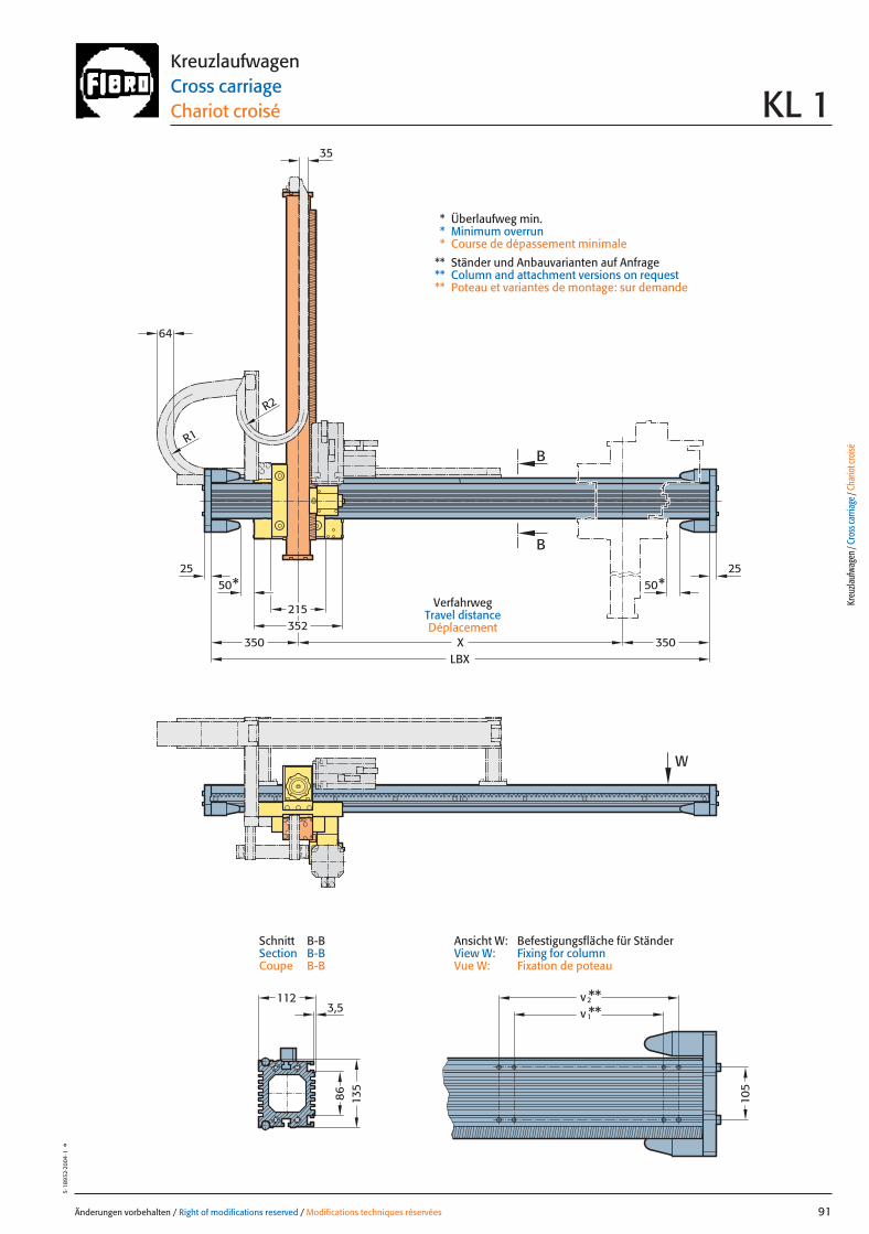
R2
50* 50*
352215
LBX
v**2v**1
25 25
B
B
W
X
R1
64
35
350 350
86
3,5112
135
105
Änderungen vorbehalten / Right of modifications reserved / Modifications techniques réservées 91
5·18
932·
2004
·1°
KreuzlaufwagenCross carriageChariot croisé KL 1
* Überlaufweg min.* Minimum overrun* Course de dépassement minimale
** Ständer und Anbauvarianten auf Anfrage** Column and attachment versions on request** Poteau et variantes de montage: sur demande
VerfahrwegTravel distanceDéplacement
Kreu
zlauf
wage
n / C
ross
carri
age /
Cha
riot c
roisé
Ansicht W: Befestigungsfläche für StänderView W: Fixing for columnVue W: Fixation de poteau
Schnitt B-BSection B-BCoupe B-B
091 27.08.2004 6:43 Uhr Seite 1
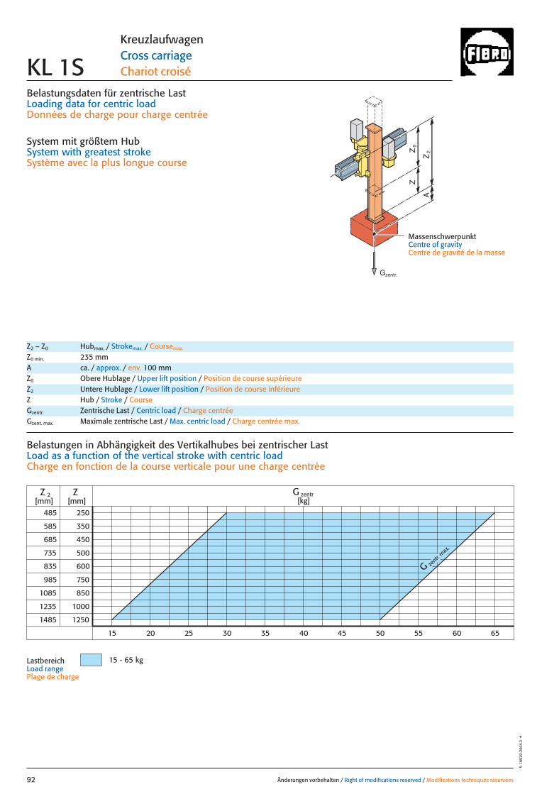
Belastungsdaten für zentrische LastLoading data for centric loadDonnées de charge pour charge centrée
System mit größtem HubSystem with greatest strokeSystème avec la plus longue course
MassenschwerpunktCentre of gravityCentre de gravité de la masse
0Z
Z
2Z
A
G zent
r max
.
485
585
985
1085
1235
1485
250
350
450
500
600
1000
1250
ZZ 2[mm] [mm]
750
850
685
735
835
15 - 65 kg
G zentr[kg]
20 3015 25 35 40 45 50 55 60 65
Änderungen vorbehalten / Right of modifications reserved / Modifications techniques réservées92
5·18
929
·200
4·2
°
KreuzlaufwagenCross carriageChariot croiséKL 1S
Z2 – Z0 Hubmax. / Strokemax. / Coursemax.
Z0 min. 235 mmA ca. / approx. / env. 100 mmZ0 Obere Hublage / Upper lift position / Position de course supérieureZ2 Untere Hublage / Lower lift position / Position de course inférieureZ Hub / Stroke / CourseGzentr. Zentrische Last / Centric load / Charge centréeGzent. max. Maximale zentrische Last / Max. centric load / Charge centrée max.
Belastungen in Abhängigkeit des Vertikalhubes bei zentrischer Last Load as a function of the vertical stroke with centric loadCharge en fonction de la course verticale pour une charge centrée
LastbereichLoad range Plage de charge
Gzentr.
092 27.08.2004 6:40 Uhr Seite 2
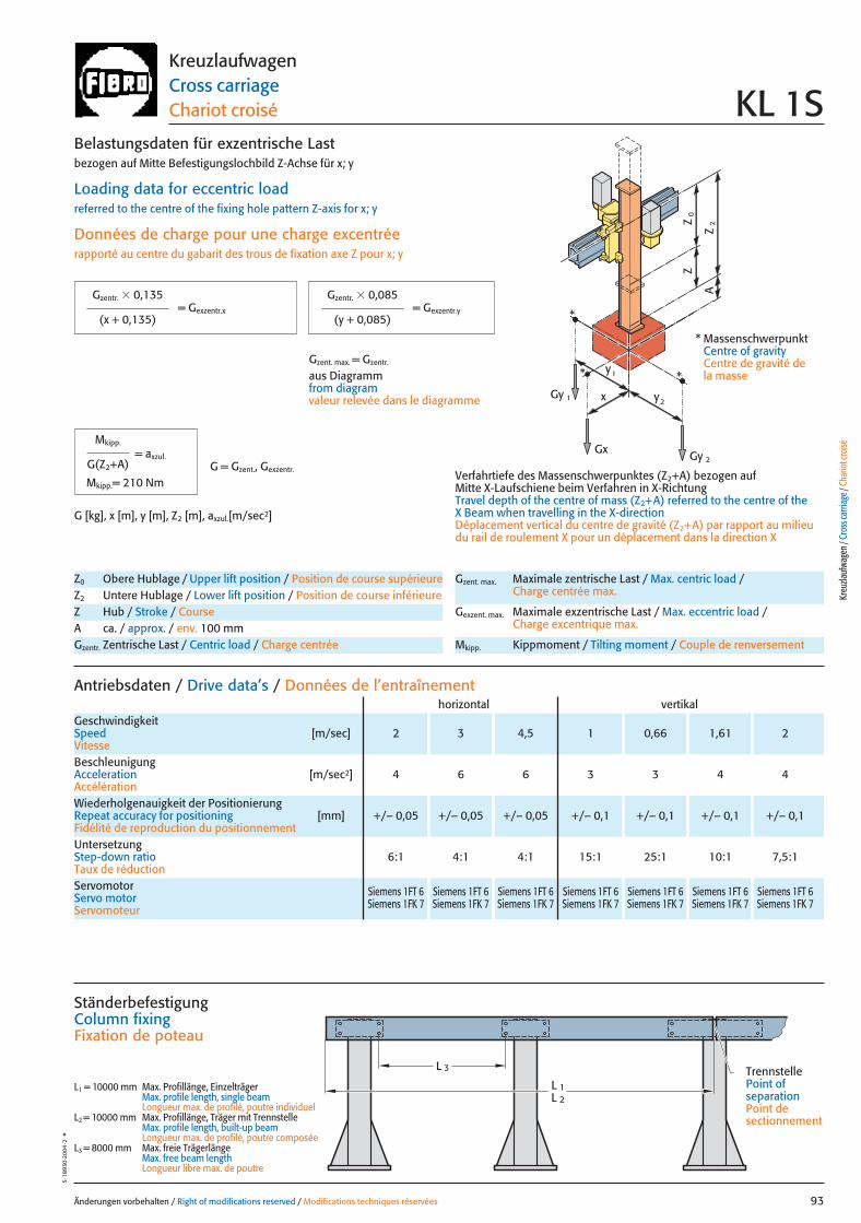
x
0Z
Z
2Z
A
Gy 2
Gy 1
Gx
2y
1y*
*
*
Änderungen vorbehalten / Right of modifications reserved / Modifications techniques réservées 93
5·18
930
·200
4·2
°KreuzlaufwagenCross carriageChariot croisé KL 1S
Z0 Obere Hublage / Upper lift position / Position de course supérieureZ2 Untere Hublage / Lower lift position / Position de course inférieureZ Hub / Stroke / CourseA ca. / approx. / env. 100 mmGzentr. Zentrische Last / Centric load / Charge centrée
Gzent. max. Maximale zentrische Last / Max. centric load / Charge centrée max.
Gexzent. max. Maximale exzentrische Last / Max. eccentric load / Charge excentrique max.
Mkipp. Kippmoment / Tilting moment / Couple de renversement
Antriebsdaten / Drive data’s / Données de l’entraînement
GeschwindigkeitSpeed [m/sec] 2 3 4,5 1 0,66 1,61 2Vitesse
horizontal vertikal
Wiederholgenauigkeit der PositionierungRepeat accuracy for positioning [mm] +/– 0,05 +/– 0,05 +/– 0,05 +/– 0,1 +/– 0,1 +/– 0,1 +/– 0,1Fidélité de reproduction du positionnement
BeschleunigungAcceleration [m/sec2] 4 6 6 3 3 4 4Accélération
Servomotor Siemens 1FT 6 Siemens 1FT 6 Siemens 1FT 6 Siemens 1FT 6 Siemens 1FT 6 Siemens 1FT 6 Siemens 1FT 6Servo motor Siemens 1FK 7 Siemens 1FK 7 Siemens 1FK 7 Siemens 1FK 7 Siemens 1FK 7 Siemens 1FK 7 Siemens 1FK 7Servomoteur
UntersetzungStep-down ratio 6:1 4:1 4:1 15:1 25:1 10:1 7,5:1Taux de réduction
= Gexzentr.y
Belastungsdaten für exzentrische Lastbezogen auf Mitte Befestigungslochbild Z-Achse für x; y
Loading data for eccentric loadreferred to the centre of the fixing hole pattern Z-axis for x; y
Données de charge pour une charge excentréerapporté au centre du gabarit des trous de fixation axe Z pour x; y
Verfahrtiefe des Massenschwerpunktes (Z2+A) bezogen auf Mitte X-Laufschiene beim Verfahren in X-RichtungTravel depth of the centre of mass (Z2+A) referred to the centre of the X Beam when travelling in the X-directionDéplacement vertical du centre de gravité (Z2+A) par rapport au milieudu rail de roulement X pour un déplacement dans la direction X
G [kg], x [m], y [m], Z2 [m], axzul.[m/sec2]
= Gexzentr.x
Gzentr. � 0,135
(x + 0,135)
Gzentr. � 0,085
(y + 0,085)
Gzent. max. = Gzentr.
aus Diagrammfrom diagramvaleur relevée dans le diagramme
* MassenschwerpunktCentre of gravityCentre de gravité dela masse
= axzul.
Mkipp.
G(Z2+A)
Mkipp.= 210 NmG = Gzent., Gexzentr.
L 3
L 1L 2
Ständerbefestigung Column fixingFixation de poteau
L1 = 10000 mm Max. Profillänge, EinzelträgerMax. profile length, single beam Longueur max. de profilé, poutre individuel
L2 = 10000 mm Max. Profillänge, Träger mit TrennstelleMax. profile length, built-up beam Longueur max. de profilé, poutre composée
L3 = 8000 mm Max. freie TrägerlängeMax. free beam length Longueur libre max. de poutre
TrennstellePoint of separationPoint de sectionnement
Kreu
zlauf
wage
n / C
ross
carri
age /
Cha
riot c
roisé
093 27.08.2004 6:39 Uhr Seite 1
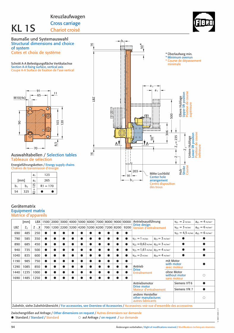
Z
Z2
306
500
20391
b2
b1
a 2
LBZ
1616
a 1
50*
Z0=
235
AA
50*
M10(4x)65
103
91
120
11
8,5
70
90
Baumaße und SystemauswahlStructural dimensions and choice of systemCotes et choix de système
Schnitt A-A Befestigungsfläche VertikalachseSection A-A fixing surface, vertical axisCoupe A-A Surface de fixation de l’axe vertical
Auswahltabellen / Selection tablesTableaux de sélectionEnergieführungsketten / Energy supply chainsChaînes de transmission d’énergie
Änderungen vorbehalten / Right of modifications reserved / Modifications techniques réservées94
5·18
931·
2004
·2°
KreuzlaufwagenCross carriageChariot croiséKL 1S
Hub
Stro
keC
ours
e
Obe
re H
ubla
geU
pper
lift
pos
ition
Posi
tion
de c
ours
esu
périe
ure
Unt
ere
Hub
lage
Low
er li
ft p
ositi
onPo
sitio
n de
cou
rse
infé
rieur
e
* Überlaufweg min.* Minimum overrun* Course de dépassement
minimale
[mm] LBX 1500 2000 3000 4000 5000 6000 7000 8000 9000 10000
LBZ Z2 Z X 700 1200 2200 3200 4200 5200 6200 7200 8200 9200
690 485 250 ● ● ● ● ● ● ● ● ● ●
790 585 350 ● ● ● ● ● ● ● ● ● ●
890 685 450 ● ● ● ● ● ● ● ● ● ●
940 735 500 ● ● ● ● ● ● ● ● ● ●
1040 835 600 ● ● ● ● ● ● ● ● ● ●
1190 985 750 ● ● ● ● ● ● ● ● ● ●
1290 1085 850 ● ● ● ● ● ● ● ● ● ●
1440 1235 1000 ● ● ● ● ● ● ● ● ● ●
1690 1485 1250 ● ● ● ● ● ● ● ● ● ●
AntriebsausführungDrive designVersion d’entraînement
vX1 = 2 m/sec aX1 = 4 m/sec2
vX2 = 3 m/sec aX2 = 6 m/sec2
vX3 = 4,5 m/sec aX3 = 6 m/sec2
vZ1 = 1 m/sec aZ1 = 3 m/sec2 ● ●
vZ2 = 0,62 m/sec aZ2 = 3 m/sec2 ● ●
vZ3 = 1,61 m/sec aZ3 = 4 m/sec2 ● ●
vZ4 = 2 m/sec aZ4 = 4 m/sec2 ● ●
AntriebDriveEntraînement
AntriebsmotorDrive motorMoteur d’entraînement
�andere Herstellerother manufacturesautres fabricants
Zubehör, siehe Zubehörübersicht / For accessories, see Overview of Accessories / Accessoires: voir vue d’ensemble des accessoires
mit Motorwith motoravec moteur
●
�ohne Motorwithout motorsans moteur
GerätematrixEquipment matrixMatrice d’appareils
a1 123
[mm] a2 265
b1 b2 R1 = 170
54 325 ● ●
● Standard / Standard / Standard � auf Anfrage / on request / sur demandeZwischengrößen auf Anfrage / Other dimensions on request / Autres dimensions sur demande
R2 =
125
Mitte LochbildCenter hole arrangementCentre disposition des trous
Siemens 1FT 6 ●
Siemens 1FK 7 ●
094 27.08.2004 6:44 Uhr Seite 2
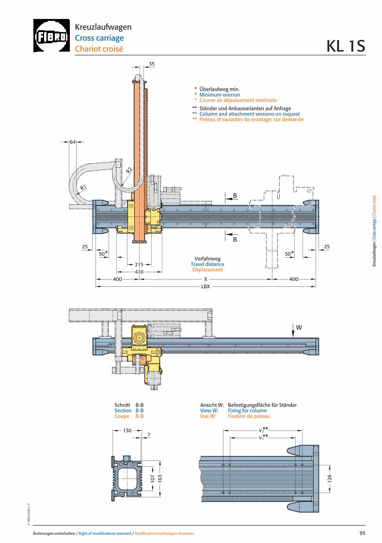
64
215410
LBX
163
130v**2v**1
X
50*25
50*25
B
B
W
R1
35
R2
400 400
107
7
126
Änderungen vorbehalten / Right of modifications reserved / Modifications techniques réservées 95
5·18
932·
2004
·2°
KreuzlaufwagenCross carriageChariot croisé KL 1S
* Überlaufweg min.* Minimum overrun* Course de dépassement minimale
** Ständer und Anbauvarianten auf Anfrage** Column and attachment versions on request** Poteau et variantes de montage: sur demande
VerfahrwegTravel distanceDéplacement
Kreu
zlauf
wage
n / C
ross
carri
age /
Cha
riot c
roisé
Ansicht W: Befestigungsfläche für StänderView W: Fixing for columnVue W: Fixation de poteau
Schnitt B-BSection B-BCoupe B-B
095 27.08.2004 6:44 Uhr Seite 1

Belastungsdaten für zentrische LastLoading data for centric loadDonnées de charge pour charge centrée
System mit größtem HubSystem with greatest strokeSystème avec la plus longue course
MassenschwerpunktCentre of gravityCentre de gravité de la masse
0Z
Z
2Z
A
G zent
r max
.
605
705
1105
1205
1355
1605
250
350
450
500
600
1000
1250
ZZ 2[mm] [mm]
70 80 90 150
750
850
805
855
955
60 140130120110100
G zentr[kg]
63 - 150 kg
Änderungen vorbehalten / Right of modifications reserved / Modifications techniques réservées96
5·18
933·
2004
·2°
KreuzlaufwagenCross carriageChariot croiséKL 2
Z2 – Z0 Hubmax. / Strokemax. / Coursemax.
Z0 min. 355 mmA ca. / approx. / env. 150 mmZ0 Obere Hublage / Upper lift position /Position de course supérieureZ2 Untere Hublage / Lower lift position / Position de course inférieureZ Hub / Stroke / CourseGzentr. Zentrische Last / Centric load / Charge centréeGzent. max. Maximale zentrische Last / Max. centric load / Charge centrée max.
Belastungen in Abhängigkeit des Vertikalhubes bei zentrischer Last Load as a function of the vertical stroke with centric loadCharge en fonction de la course verticale pour une charge centrée
LastbereichLoad rangePlage de charge
Gzentr.
096 27.08.2004 6:40 Uhr Seite 2
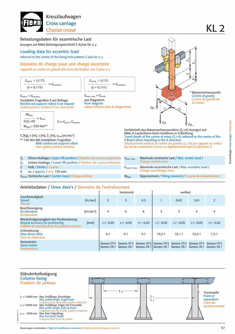
x
0Z
Z
2Z
A
Gy 2
Gy 1
Gx
2y
1y*
*
*
Änderungen vorbehalten / Right of modifications reserved / Modifications techniques réservées 97
5·18
934
·200
4·2
°KreuzlaufwagenCross carriageChariot croisé KL 2
Antriebsdaten / Drive data’s / Données de l’entraînement
GeschwindigkeitSpeed [m/sec] 2 3 4,5 1 0,62 1,61 2Vitesse
horizontal vertikal
Wiederholgenauigkeit der PositionierungRepeat accuracy for positioning [mm] +/– 0,05 +/– 0,05 +/– 0,05 +/– 0,05 +/– 0,05 +/– 0,05 +/– 0,05Fidélité de reproduction du positionnement
BeschleunigungAcceleration [m/sec2] 4 6 6 3 3 4 4Accélération
Servomotor Siemens 1FT 6 Siemens 1FT 6 Siemens 1FT 6 Siemens 1FT 6 Siemens 1FT 6 Siemens 1FT 6 Siemens 1FT 6Servo motor Siemens 1FK 7 Siemens 1FK 7 Siemens 1FK 7 Siemens 1FK 7 Siemens 1FK 7 Siemens 1FK 7 Siemens 1FK 7Servomoteur
UntersetzungStep-down ratio 6:1 4:1 4:1 10,2:1 16,1:1 10,2:1 7,5:1Taux de réduction
Z0 Obere Hublage / Upper lift position / Position de course supérieureZ2 Untere Hublage / Lower lift position / Position de course inférieureZ Hub / Stroke / CourseA ca. / approx. / env. 150 mmGzentr. Zentrische Last / Centric load / Charge centrée
Gzent. max. Maximale zentrische Last / Max. centric load / Charge centrée max.
Gexzent. max. Maximale exzentrische Last / Max. eccentric load / Charge excentrique max.
Mkipp. Kippmoment / Tilting moment / Couple de renversement
= Gexzentr.y
Belastungsdaten für exzentrische Lastbezogen auf Mitte Befestigungslochbild Z-Achse für x; y
Loading data for eccentric loadreferred to the centre of the fixing hole pattern Z-axis for x; y
Données de charge pour une charge excentréerapporté au centre du gabarit des trous de fixation axe Z pour x; y
Verfahrtiefe des Massenschwerpunktes (Z2+A) bezogen auf Mitte X-Laufschiene beim Verfahren in X-RichtungTravel depth of the centre of mass (Z2+A) referred to the centre of the X Beam when travelling in the X-directionDéplacement vertical du centre de gravité (Z2+A) par rapport au milieudu rail de roulement X pour un déplacement dans la direction X
G [kg], x [m], y [m], Z2 [m], axzul.[m/sec2]** 700 Nm Mit verstärkten Tragrollen
With reinforced support rollersAvec galets porteur renforce
= Gexzentr.x
Gzentr. � 0,175
(x + 0,175)
Gzentr. � 0,131
(y + 0,131)
Gzentr. = Gexzentr.
Verstärkte Tragrollen X auf AnfrageReinforced support rollers X on requestGalets porteur renforcé X sur demande
Gzent. max. = Gzentr.
aus Diagrammfrom diagramvaleur relevée dans le diagramme
* MassenschwerpunktCentre of gravityCentre de gravité dela masse
= axzul.
Mkipp.
G(Z2+A)
Mkipp.= 350 Nm**G = Gzent., Gexzentr.
L 3
L 1L 2
Ständerbefestigung Column fixingFixation de poteau
L1 = 10000 mm Max. Profillänge, EinzelträgerMax. profile length, single beam Longueur max. de profilé, poutre individuel
L2 = 10000 mm Max. Profillänge, Träger mit TrennstelleMax. profile length, built-up beam Longueur max. de profilé, poutre composée
L3 = 5000 mm Max. freie TrägerlängeMax. free beam length Longueur libre max. de poutre
TrennstellePoint of separationPoint de sectionnement
Kreu
zlauf
wage
n / C
ross
carri
age /
Cha
riot c
roisé
097 27.08.2004 6:41 Uhr Seite 1
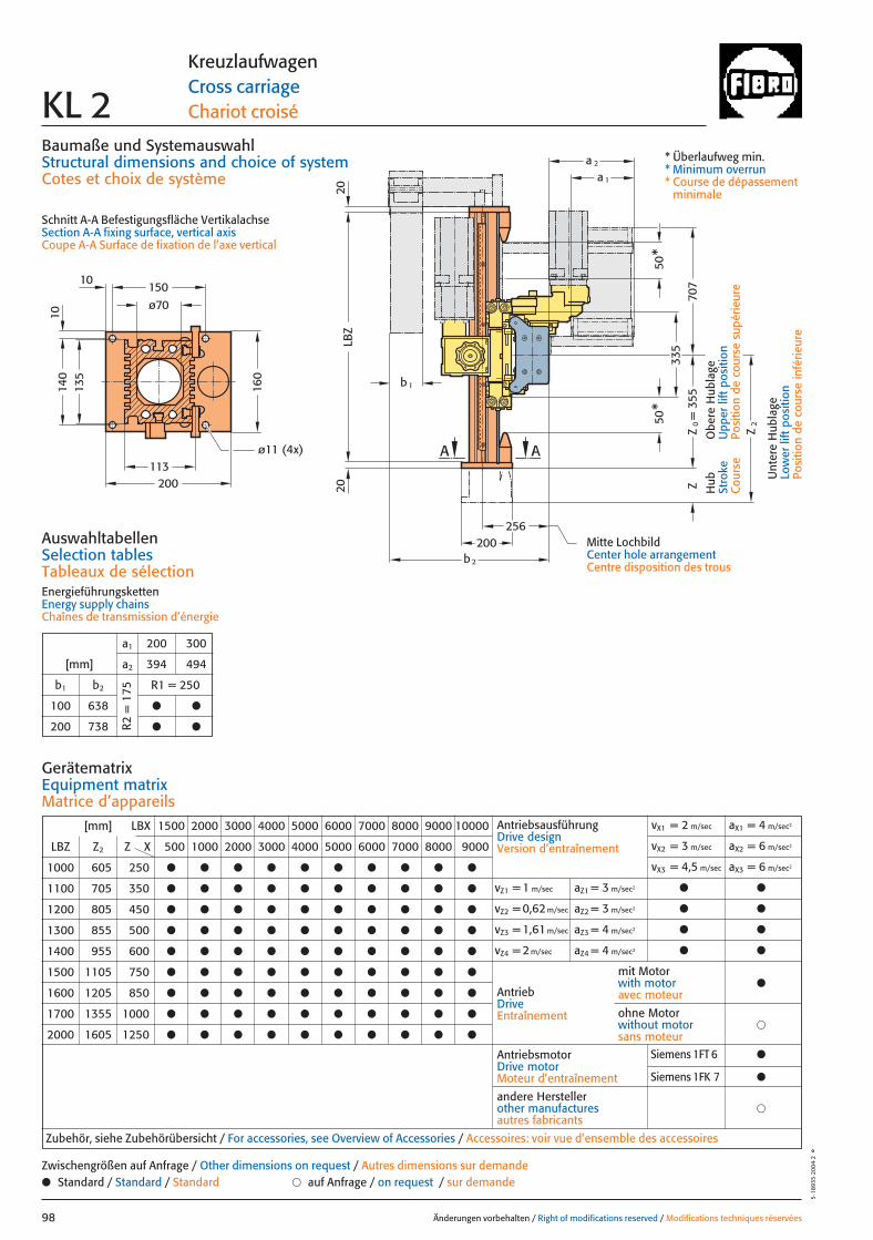
113
135
335
256200
A A
10
1014
0
ø70150
200
160
ø11 (4x)
707
Z
Z2
b 2
LBZ
50*
50*
a 1
a 2
b1
= 3
55Z
0
2020
Baumaße und SystemauswahlStructural dimensions and choice of systemCotes et choix de système
Schnitt A-A Befestigungsfläche VertikalachseSection A-A fixing surface, vertical axisCoupe A-A Surface de fixation de l’axe vertical
Änderungen vorbehalten / Right of modifications reserved / Modifications techniques réservées98
5·18
935
·200
4·2
°
KreuzlaufwagenCross carriageChariot croiséKL 2
Hub
Stro
keC
ours
e
Obe
re H
ubla
geU
pper
lift
pos
ition
Posi
tion
de c
ours
e su
périe
ure
Unt
ere
Hub
lage
Low
er li
ft p
ositi
onPo
sitio
n de
cou
rse
infé
rieur
e
* Überlaufweg min.* Minimum overrun* Course de dépassement
minimale
AuswahltabellenSelection tablesTableaux de sélectionEnergieführungskettenEnergy supply chainsChaînes de transmission d’énergie
a1 200 300
[mm] a2 394 494
b1 b2 R1 = 250
100 638 ● ●
200 738 ● ●R2 =
175
Mitte LochbildCenter hole arrangementCentre disposition des trous
GerätematrixEquipment matrixMatrice d’appareils
[mm] LBX 1500 2000 3000 4000 5000 6000 7000 8000 9000 10000
LBZ Z2 Z X 500 1000 2000 3000 4000 5000 6000 7000 8000 9000
1000 605 250 ● ● ● ● ● ● ● ● ● ●
1100 705 350 ● ● ● ● ● ● ● ● ● ●
1200 805 450 ● ● ● ● ● ● ● ● ● ●
1300 855 500 ● ● ● ● ● ● ● ● ● ●
1400 955 600 ● ● ● ● ● ● ● ● ● ●
1500 1105 750 ● ● ● ● ● ● ● ● ● ●
1600 1205 850 ● ● ● ● ● ● ● ● ● ●
1700 1355 1000 ● ● ● ● ● ● ● ● ● ●
2000 1605 1250 ● ● ● ● ● ● ● ● ● ●
AntriebsausführungDrive designVersion d’entraînement
vX1 = 2 m/sec aX1 = 4 m/sec2
vX2 = 3 m/sec aX2 = 6 m/sec2
vX3 = 4,5 m/sec aX3 = 6 m/sec2
vZ1 = 1 m/sec aZ1 = 3 m/sec2 ● ●
vZ2 = 0,62 m/sec aZ2 = 3 m/sec2 ● ●
vZ3 = 1,61 m/sec aZ3 = 4 m/sec2 ● ●
vZ4 = 2 m/sec aZ4 = 4 m/sec2 ● ●
AntriebDriveEntraînement
AntriebsmotorDrive motorMoteur d’entraînement
�andere Herstellerother manufacturesautres fabricants
Zubehör, siehe Zubehörübersicht / For accessories, see Overview of Accessories / Accessoires: voir vue d’ensemble des accessoires
mit Motorwith motoravec moteur
●
�ohne Motorwithout motorsans moteur
● Standard / Standard / Standard � auf Anfrage / on request / sur demandeZwischengrößen auf Anfrage / Other dimensions on request / Autres dimensions sur demande
Siemens 1FT 6 ●
Siemens 1FK 7 ●
098 27.08.2004 6:41 Uhr Seite 2
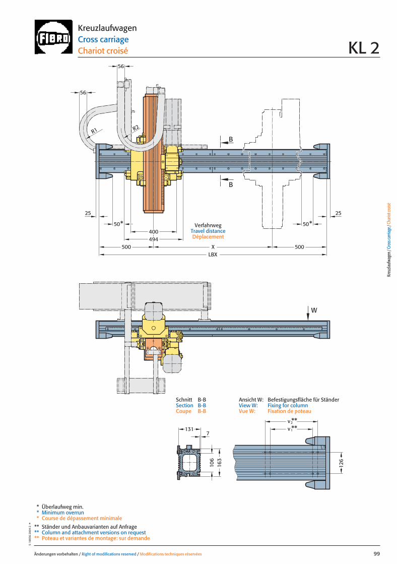
Änderungen vorbehalten / Right of modifications reserved / Modifications techniques réservées 99
5·18
936
·200
4·2
°KreuzlaufwagenCross carriageChariot croisé KL 2
VerfahrwegTravel distanceDéplacement
56
494400
W
50* 50*
R1 R2
56
2525
500LBX
X 500
B
B
106
v**2v
1**
126
163
1317
* Überlaufweg min.* Minimum overrun* Course de dépassement minimale
** Ständer und Anbauvarianten auf Anfrage** Column and attachment versions on request** Poteau et variantes de montage: sur demande
Kreu
zlauf
wage
n / C
ross
carri
age /
Cha
riot c
roisé
Ansicht W: Befestigungsfläche für StänderView W: Fixing for columnVue W: Fixation de poteau
Schnitt B-BSection B-BCoupe B-B
099 27.08.2004 6:41 Uhr Seite 1
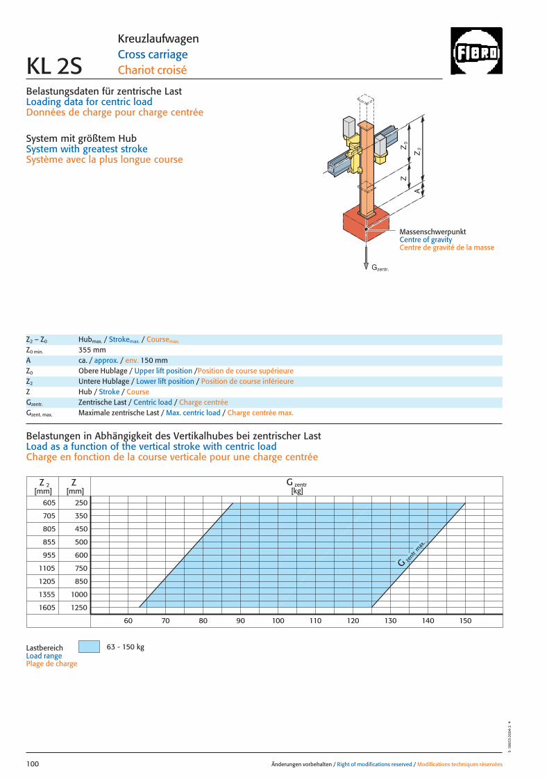
Belastungsdaten für zentrische LastLoading data for centric loadDonnées de charge pour charge centrée
System mit größtem HubSystem with greatest strokeSystème avec la plus longue course
MassenschwerpunktCentre of gravityCentre de gravité de la masse
0Z
Z
2Z
A
G zent
r max
.
605
705
1105
1205
1355
1605
250
350
450
500
600
1000
1250
ZZ 2[mm] [mm]
70 80 90 150
750
850
805
855
955
60 140130120110100
G zentr[kg]
63 - 150 kg
Änderungen vorbehalten / Right of modifications reserved / Modifications techniques réservées100
5·18
933·
2004
·2°
KreuzlaufwagenCross carriageChariot croiséKL 2S
Z2 – Z0 Hubmax. / Strokemax. / Coursemax.
Z0 min. 355 mmA ca. / approx. / env. 150 mmZ0 Obere Hublage / Upper lift position /Position de course supérieureZ2 Untere Hublage / Lower lift position / Position de course inférieureZ Hub / Stroke / CourseGzentr. Zentrische Last / Centric load / Charge centréeGzent. max. Maximale zentrische Last / Max. centric load / Charge centrée max.
Belastungen in Abhängigkeit des Vertikalhubes bei zentrischer Last Load as a function of the vertical stroke with centric loadCharge en fonction de la course verticale pour une charge centrée
LastbereichLoad rangePlage de charge
Gzentr.
100 27.08.2004 6:44 Uhr Seite 2

x
0Z
Z
2Z
A
Gy 2
Gy 1
Gx
2y
1y*
*
*
Änderungen vorbehalten / Right of modifications reserved / Modifications techniques réservées 101
5·18
934
·200
4·2
°KreuzlaufwagenCross carriageChariot croisé KL 2S
Z0 Obere Hublage / Upper lift position / Position de course supérieureZ2 Untere Hublage / Lower lift position / Position de course inférieureZ Hub / Stroke / CourseA ca. / approx. / env. 150 mmGzentr. Zentrische Last / Centric load / Charge centrée
Gzent. max. Maximale zentrische Last / Max. centric load / Charge centrée max.
Gexzent. max. Maximale exzentrische Last / Max. eccentric load / Charge excentrique max.
Mkipp. Kippmoment / Tilting moment / Couple de renversement
= Gexzentr.y
Belastungsdaten für exzentrische Lastbezogen auf Mitte Befestigungslochbild Z-Achse für x; y
Loading data for eccentric loadreferred to the centre of the fixing hole pattern Z-axis for x; y
Données de charge pour une charge excentréerapporté au centre du gabarit des trous de fixation axe Z pour x; y
Verfahrtiefe des Massenschwerpunktes (Z2+A) bezogen auf Mitte X-Laufschiene beim Verfahren in X-RichtungTravel depth of the centre of mass (Z2+A) referred to the centre of the X Beam when travelling in the X-directionDéplacement vertical du centre de gravité (Z2+A) par rapport au milieudu rail de roulement X pour un déplacement dans la direction X
G [kg], x [m], y [m], Z2 [m], axzul.[m/sec2]** 700 Nm Mit verstärkten Tragrollen
With reinforced support rollersAvec galets porteur renforce
= Gexzentr.x
Gzentr. � 0,175
(x + 0,175)
Gzentr. � 0,131
(y + 0,131)
Gzentr. = Gexzentr.
Verstärkte Tragrollen X auf AnfrageReinforced support rollers X on requestGalets porteur renforcé X sur demande
Gzent. max. = Gzentr.
aus Diagrammfrom diagramvaleur relevée dans le diagramme
* MassenschwerpunktCentre of gravityCentre de gravité dela masse
= axzul.
Mkipp.
G(Z2+A)
Mkipp.= 350 Nm**G = Gzent., Gexzentr.
L 3
L 1L 2
Ständerbefestigung Column fixingFixation de poteau
L1 = 10000 mm Max. Profillänge, EinzelträgerMax. profile length, single beam Longueur max. de profilé, poutre individuel
L2 = 10000 mm Max. Profillänge, Träger mit TrennstelleMax. profile length, built-up beam Longueur max. de profilé, poutre composée
L3 = 8000 mm Max. freie TrägerlängeMax. free beam length Longueur libre max. de poutre
TrennstellePoint of separationPoint de sectionnement
Kreu
zlauf
wage
n / C
ross
carri
age /
Cha
riot c
roisé
Antriebsdaten / Drive data’s / Données de l’entraînement
GeschwindigkeitSpeed [m/sec] 2 3 4,5 1 0,62 1,61 2Vitesse
horizontal vertikal
Wiederholgenauigkeit der PositionierungRepeat accuracy for positioning [mm] +/– 0,05 +/– 0,05 +/– 0,05 +/– 0,05 +/– 0,05 +/– 0,05 +/– 0,05Fidélité de reproduction du positionnement
BeschleunigungAcceleration [m/sec2] 4 6 6 3 3 4 4Accélération
Servomotor Siemens 1FT 6 Siemens 1FT 6 Siemens 1FT 6 Siemens 1FT 6 Siemens 1FT 6 Siemens 1FT 6 Siemens 1FT 6Servo motor Siemens 1FK 7 Siemens 1FK 7 Siemens 1FK 7 Siemens 1FK 7 Siemens 1FK 7 Siemens 1FK 7 Siemens 1FK 7Servomoteur
UntersetzungStep-down ratio 6:1 4:1 4:1 10,2:1 16,1:1 10,2:1 7,5:1Taux de réduction
101 27.08.2004 6:44 Uhr Seite 1
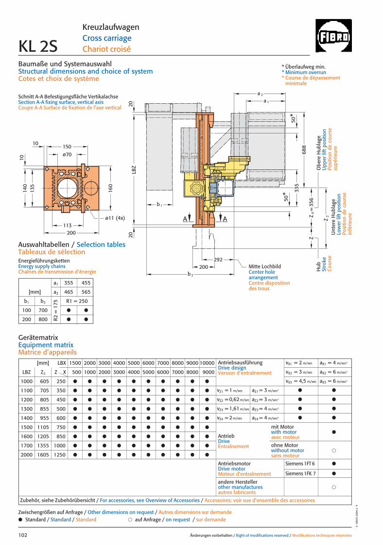
ZZ
0=
Z2
LBZ
b 1
b2
a 1
a 2
A A
50*
50*
113
135
10
1014
0
ø70150
200
160
ø11 (4x)
200
2020
292
335
688
356
Baumaße und SystemauswahlStructural dimensions and choice of systemCotes et choix de système
Schnitt A-A Befestigungsfläche VertikalachseSection A-A fixing surface, vertical axisCoupe A-A Surface de fixation de l’axe vertical
Änderungen vorbehalten / Right of modifications reserved / Modifications techniques réservées102
5·18
935
·200
4·2
°
KreuzlaufwagenCross carriageChariot croiséKL 2S
Hub
Stro
keC
ours
e
Obe
re H
ubla
geU
pper
lift
pos
ition
Posi
tion
de c
ours
esu
périe
ure
Unt
ere
Hub
lage
Low
er li
ft p
ositi
onPo
sitio
n de
cou
rse
infé
rieur
e
* Überlaufweg min.* Minimum overrun* Course de dépassement
minimale
Auswahltabellen / Selection tablesTableaux de sélectionEnergieführungskettenEnergy supply chainsChaînes de transmission d’énergie
a1 355 455
[mm] a2 465 565
b1 b2 R1 = 250
100 700 ● ●
200 800 ● ●R2 =
175
GerätematrixEquipment matrixMatrice d’appareils
Mitte LochbildCenter hole arrangementCentre disposition des trous
[mm] LBX 1500 2000 3000 4000 5000 6000 7000 8000 9000 10000
LBZ Z2 Z X 500 1000 2000 3000 4000 5000 6000 7000 8000 9000
1000 605 250 ● ● ● ● ● ● ● ● ● ●
1100 705 350 ● ● ● ● ● ● ● ● ● ●
1200 805 450 ● ● ● ● ● ● ● ● ● ●
1300 855 500 ● ● ● ● ● ● ● ● ● ●
1400 955 600 ● ● ● ● ● ● ● ● ● ●
1500 1105 750 ● ● ● ● ● ● ● ● ● ●
1600 1205 850 ● ● ● ● ● ● ● ● ● ●
1700 1355 1000 ● ● ● ● ● ● ● ● ● ●
2000 1605 1250 ● ● ● ● ● ● ● ● ● ●
AntriebsausführungDrive designVersion d’entraînement
vX1 = 2 m/sec aX1 = 4 m/sec2
vX2 = 3 m/sec aX2 = 6 m/sec2
vX3 = 4,5 m/sec aX3 = 6 m/sec2
vZ1 = 1 m/sec aZ1 = 3 m/sec2 ● ●
vZ2 = 0,62 m/sec aZ2 = 3 m/sec2 ● ●
vZ3 = 1,61 m/sec aZ3 = 4 m/sec2 ● ●
vZ4 = 2 m/sec aZ4 = 4 m/sec2 ● ●
AntriebDriveEntraînement
AntriebsmotorDrive motorMoteur d’entraînement
�andere Herstellerother manufacturesautres fabricants
Zubehör, siehe Zubehörübersicht / For accessories, see Overview of Accessories / Accessoires: voir vue d’ensemble des accessoires
mit Motorwith motoravec moteur
●
�ohne Motorwithout motorsans moteur
● Standard / Standard / Standard � auf Anfrage / on request / sur demandeZwischengrößen auf Anfrage / Other dimensions on request / Autres dimensions sur demande
Siemens 1FT 6 ●
Siemens 1FK 7 ●
102 27.08.2004 6:43 Uhr Seite 2
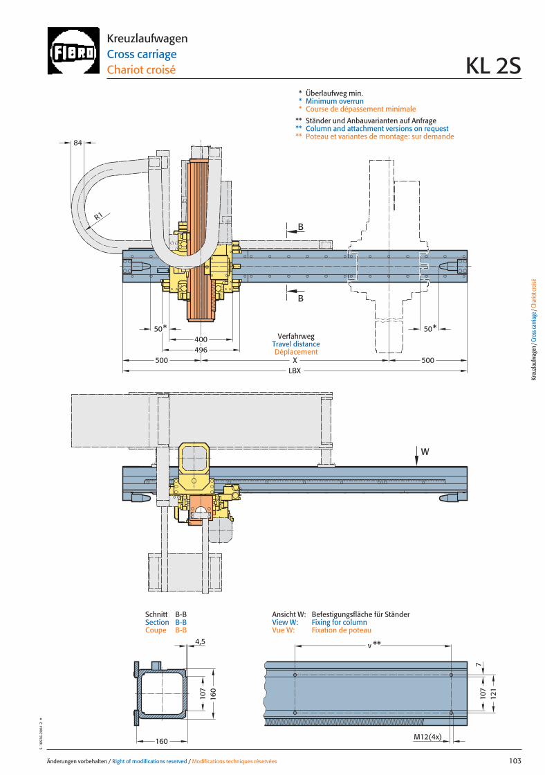
Änderungen vorbehalten / Right of modifications reserved / Modifications techniques réservées 103
5·18
936
·200
4·2
°KreuzlaufwagenCross carriageChariot croisé KL 2S
VerfahrwegTravel distanceDéplacement
7
4,5
50*50*400496
LBX
v **
X
B
B
W
500 500
84
R1
160
107
107
121
M12(4x)
160
* Überlaufweg min.* Minimum overrun* Course de dépassement minimale
** Ständer und Anbauvarianten auf Anfrage** Column and attachment versions on request** Poteau et variantes de montage: sur demande
Kreu
zlauf
wage
n / C
ross
carri
age /
Cha
riot c
roisé
Ansicht W: Befestigungsfläche für StänderView W: Fixing for columnVue W: Fixation de poteau
Schnitt B-BSection B-BCoupe B-B
103 27.08.2004 6:42 Uhr Seite 1
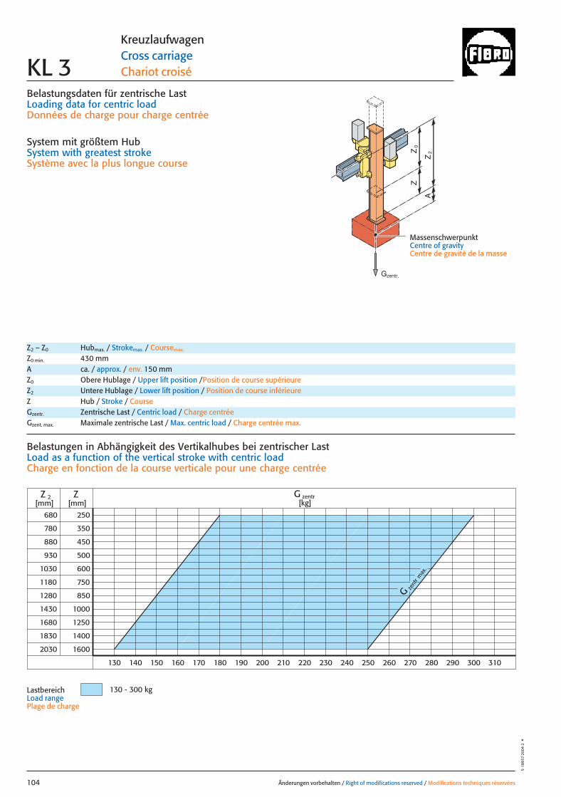
Belastungsdaten für zentrische LastLoading data for centric loadDonnées de charge pour charge centrée
System mit größtem HubSystem with greatest strokeSystème avec la plus longue course
MassenschwerpunktCentre of gravityCentre de gravité de la masse
0Z
Z
2Z
A
zent
r
G
max
.
680
780
880
930
1030
1180
1280
1430
1680
1830
2030
250
350
450
500
600
750
850
1000
1250
1400
1600
Z
130 140 150 160 170 180 190 200 210 220 230 240 250 260 270 280 290 300 310
Z 2 G zentr[kg][mm] [mm]
130 - 300 kg
Änderungen vorbehalten / Right of modifications reserved / Modifications techniques réservées104
5·18
937·
2004
·2°
KreuzlaufwagenCross carriageChariot croiséKL 3
Z2 – Z0 Hubmax. / Strokemax. / Coursemax.
Z0 min. 430 mmA ca. / approx. / env. 150 mmZ0 Obere Hublage / Upper lift position /Position de course supérieureZ2 Untere Hublage / Lower lift position / Position de course inférieureZ Hub / Stroke / CourseGzentr. Zentrische Last / Centric load / Charge centréeGzent. max. Maximale zentrische Last / Max. centric load / Charge centrée max.
Belastungen in Abhängigkeit des Vertikalhubes bei zentrischer Last Load as a function of the vertical stroke with centric loadCharge en fonction de la course verticale pour une charge centrée
Lastbereich Load rangePlage de charge
Gzentr.
104 27.08.2004 6:41 Uhr Seite 2
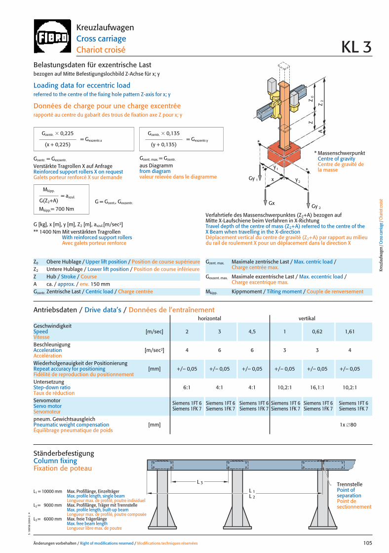
x
0Z
Z
2Z
A
Gy 2
Gy 1
Gx
2y
1y*
*
*
Änderungen vorbehalten / Right of modifications reserved / Modifications techniques réservées 105
5·18
938
·200
4·2
°KreuzlaufwagenCross carriageChariot croisé KL 3
pneum. GewichtsausgleichPneumatic weight compensation [mm] 1x �80Équilibrage pneumatique de poids
Antriebsdaten / Drive data’s / Données de l’entraînement
GeschwindigkeitSpeed [m/sec] 2 3 4,5 1 0,62 1,61Vitesse
horizontal vertikal
Wiederholgenauigkeit der PositionierungRepeat accuracy for positioning [mm] +/– 0,05 +/– 0,05 +/– 0,05 +/– 0,05 +/– 0,05 +/– 0,05Fidélité de reproduction du positionnement
BeschleunigungAcceleration [m/sec2] 4 6 6 3 3 4Accélération
Servomotor Siemens 1FT 6 Siemens 1FT 6 Siemens 1FT 6 Siemens 1FT 6 Siemens 1FT 6 Siemens 1FT 6Servo motor Siemens 1FK 7 Siemens 1FK 7 Siemens 1FK 7 Siemens 1FK 7 Siemens 1FK 7 Siemens 1FK 7Servomoteur
UntersetzungStep-down ratio 6:1 4:1 4:1 10,2:1 16,1:1 10,2:1Taux de réduction
Z0 Obere Hublage / Upper lift position / Position de course supérieureZ2 Untere Hublage / Lower lift position / Position de course inférieureZ Hub / Stroke / CourseA ca. / approx. / env. 150 mmGzentr. Zentrische Last / Centric load / Charge centrée
Gzent. max. Maximale zentrische Last / Max. centric load / Charge centrée max.
Gexzent. max. Maximale exzentrische Last / Max. eccentric load / Charge excentrique max.
Mkipp. Kippmoment / Tilting moment / Couple de renversement
= Gexzentr.y
Belastungsdaten für exzentrische Lastbezogen auf Mitte Befestigungslochbild Z-Achse für x; y
Loading data for eccentric loadreferred to the centre of the fixing hole pattern Z-axis for x; y
Données de charge pour une charge excentréerapporté au centre du gabarit des trous de fixation axe Z pour x; y
Verfahrtiefe des Massenschwerpunktes (Z2+A) bezogen auf Mitte X-Laufschiene beim Verfahren in X-RichtungTravel depth of the centre of mass (Z2+A) referred to the centre of the X Beam when travelling in the X-directionDéplacement vertical du centre de gravité (Z2+A) par rapport au milieudu rail de roulement X pour un déplacement dans la direction X
G [kg], x [m], y [m], Z2 [m], axzul.[m/sec2]** 1400 Nm Mit verstärkten Tragrollen
With reinforced support rollersAvec galets porteur renforce
= Gexzentr.x
Gzentr. � 0,225
(x + 0,225)
Gzentr. � 0,135
(y + 0,135)
Gzentr. = Gexzentr.
Verstärkte Tragrollen X auf AnfrageReinforced support rollers X on requestGalets porteur renforcé X sur demande
Gzent. max. = Gzentr.
aus Diagrammfrom diagramvaleur relevée dans le diagramme
* MassenschwerpunktCentre of gravityCentre de gravité dela masse
= axzul.
Mkipp.
G(Z2+A)
Mkipp.= 700 NmG = Gzent., Gexzentr.
L 3
L 1L 2
Ständerbefestigung Column fixingFixation de poteau
L1 = 10000 mm Max. Profillänge, EinzelträgerMax. profile length, single beam Longueur max. de profilé, poutre individuel
L2 = 9000 mm Max. Profillänge, Träger mit TrennstelleMax. profile length, built-up beam Longueur max. de profilé, poutre composée
L3 = 6000 mm Max. freie TrägerlängeMax. free beam length Longueur libre max. de poutre
TrennstellePoint of separationPoint de sectionnement
Kreu
zlauf
wage
n / C
ross
carri
age /
Cha
riot c
roisé
105 27.08.2004 6:41 Uhr Seite 1
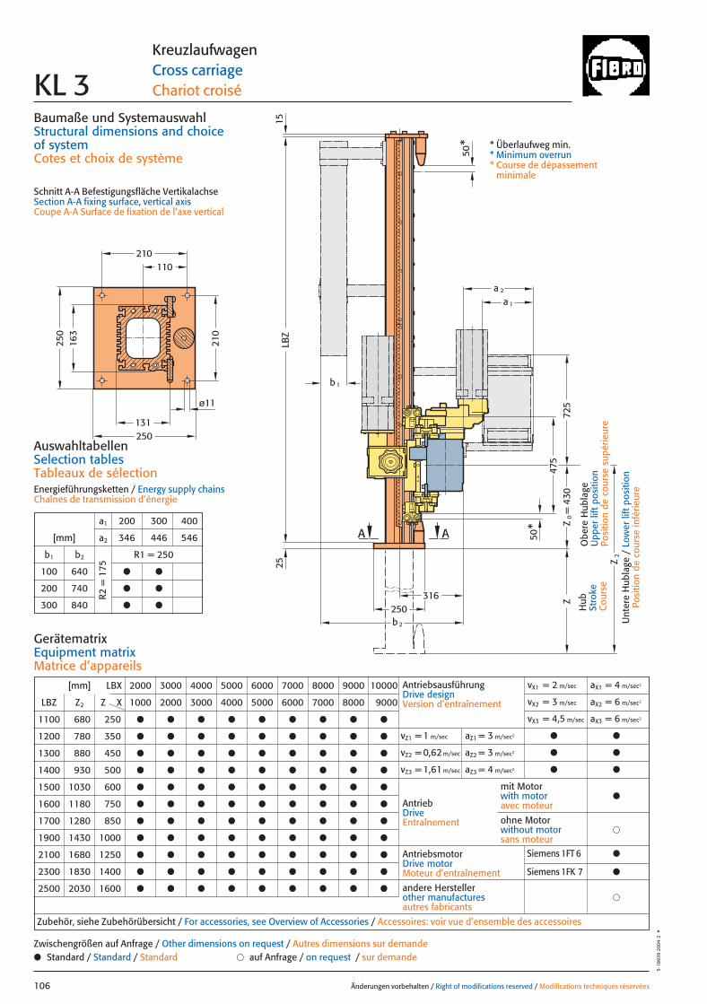
110
131
163
= 4
30
a 1
a 2
25 Z2
LBZ
ZZ
0
475
725
316250
A
ø11
250
210
250
210
A
50*
15
b 2
50*
b 1
Baumaße und SystemauswahlStructural dimensions and choice of systemCotes et choix de système
Schnitt A-A Befestigungsfläche VertikalachseSection A-A fixing surface, vertical axisCoupe A-A Surface de fixation de l’axe vertical
Änderungen vorbehalten / Right of modifications reserved / Modifications techniques réservées106
5·18
939
·200
4·2
°
KreuzlaufwagenCross carriageChariot croiséKL 3
Hub
Stro
keC
ours
e
Obe
re H
ubla
geU
pper
lift
pos
ition
Posi
tion
de c
ours
e su
périe
ure
Unt
ere
Hub
lage
/ L
ower
lift
pos
ition
Posi
tion
de c
ours
e in
férie
ure
* Überlaufweg min.* Minimum overrun* Course de dépassement
minimale
AuswahltabellenSelection tablesTableaux de sélectionEnergieführungsketten / Energy supply chainsChaînes de transmission d’énergie
a1 200 300 400
[mm] a2 346 446 546
b1 b2 R1 = 250
100 640 ● ●
200 740 ● ●
300 840 ● ●
R2 =
175
[mm] LBX 2000 3000 4000 5000 6000 7000 8000 9000 10000
LBZ Z2 Z X 1000 2000 3000 4000 5000 6000 7000 8000 9000
1100 680 250 ● ● ● ● ● ● ● ● ●
1200 780 350 ● ● ● ● ● ● ● ● ●
1300 880 450 ● ● ● ● ● ● ● ● ●
1400 930 500 ● ● ● ● ● ● ● ● ●
1500 1030 600 ● ● ● ● ● ● ● ● ●
1600 1180 750 ● ● ● ● ● ● ● ● ●
1700 1280 850 ● ● ● ● ● ● ● ● ●
1900 1430 1000 ● ● ● ● ● ● ● ● ●
2100 1680 1250 ● ● ● ● ● ● ● ● ●
2300 1830 1400 ● ● ● ● ● ● ● ● ●
2500 2030 1600 ● ● ● ● ● ● ● ● ●
AntriebsausführungDrive designVersion d’entraînement
vX1 = 2 m/sec aX1 = 4 m/sec2
vX2 = 3 m/sec aX2 = 6 m/sec2
vX3 = 4,5 m/sec aX3 = 6 m/sec2
vZ1 = 1 m/sec aZ1 = 3 m/sec2 ● ●
vZ2 = 0,62 m/sec aZ2 = 3 m/sec2 ● ●
vZ3 = 1,61 m/sec aZ3 = 4 m/sec2 ● ●
AntriebDriveEntraînement
AntriebsmotorDrive motorMoteur d’entraînement
�andere Herstellerother manufacturesautres fabricants
Zubehör, siehe Zubehörübersicht / For accessories, see Overview of Accessories / Accessoires: voir vue d’ensemble des accessoires
mit Motorwith motoravec moteur
●
�ohne Motorwithout motorsans moteur
GerätematrixEquipment matrixMatrice d’appareils
● Standard / Standard / Standard � auf Anfrage / on request / sur demandeZwischengrößen auf Anfrage / Other dimensions on request / Autres dimensions sur demande
Siemens 1FT 6 ●
Siemens 1FK 7 ●
106 27.08.2004 6:41 Uhr Seite 2
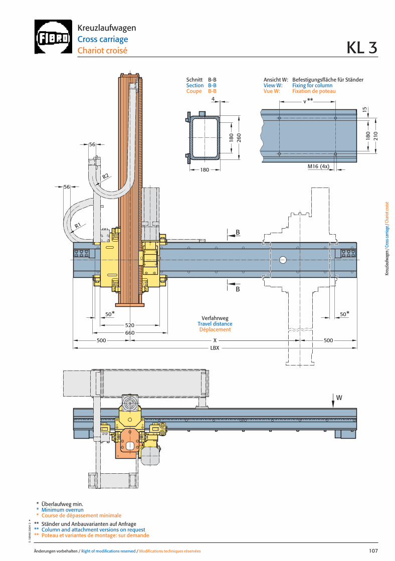
Änderungen vorbehalten / Right of modifications reserved / Modifications techniques réservées 107
5·18
940
·200
4·2
°KreuzlaufwagenCross carriageChariot croisé KL 3
VerfahrwegTravel distanceDéplacement
56
56
500500LBX
520
W
X660
50*50*
R1
R2
B
B
180
210
180
260
180
v **
M16 (4x)
15
4
* Überlaufweg min.* Minimum overrun* Course de dépassement minimale
** Ständer und Anbauvarianten auf Anfrage** Column and attachment versions on request** Poteau et variantes de montage: sur demande
Kreu
zlauf
wage
n / C
ross
carri
age /
Cha
riot c
roisé
Ansicht W: Befestigungsfläche für StänderView W: Fixing for columnVue W: Fixation de poteau
Schnitt B-BSection B-BCoupe B-B
107 27.08.2004 6:41 Uhr Seite 1

Belastungsdaten für zentrische LastLoading data for centric loadDonnées de charge pour charge centrée
System mit größtem HubSystem with greatest strokeSystème avec la plus longue course
MassenschwerpunktCentre of gravityCentre de gravité de la masse
0Z
Z
2Z
A
G zentr
max.
810
910
1010
1060
1160
1310
1410
1560
1810
1960
2160
250
350
450
500
600
750
850
1000
1250
1400
1600
Z
360
Z 2[mm] [mm]
350340330320310300290280270260 370 380 390 400 410 420 430 440 450 460
G zentr[kg]
270 - 435 kg
Änderungen vorbehalten / Right of modifications reserved / Modifications techniques réservées108
5·18
941·
2004
·2°
KreuzlaufwagenCross carriageChariot croiséKL 4
Z2 – Z0 Hubmax. / Strokemax. / Coursemax.
Z0 min. 560 mmA ca. / approx. / env. 200 mmZ0 Obere Hublage / Upper lift position /Position de course supérieureZ2 Untere Hublage / Lower lift position / Position de course inférieureZ Hub / Stroke / CourseGzentr. Zentrische Last / Centric load / Charge centréeGzent. max. Maximale zentrische Last / Max. centric load / Charge centrée max.
Belastungen in Abhängigkeit des Vertikalhubes bei zentrischer Last Load as a function of the vertical stroke with centric loadCharge en fonction de la course verticale pour une charge centrée
LastbereichLoad rangePlage de charge
Gzentr.
108 27.08.2004 6:41 Uhr Seite 2
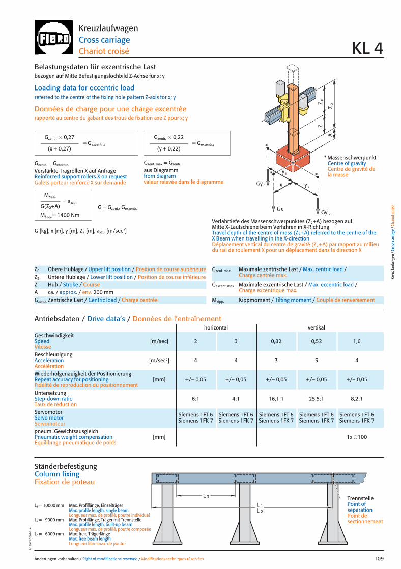
x
0Z
Z
2Z
A
Gy 2
Gy 1
Gx
2y
1y*
*
*
Änderungen vorbehalten / Right of modifications reserved / Modifications techniques réservées 109
5·18
942·
2003
·1°
KreuzlaufwagenCross carriageChariot croisé KL 4
pneum. GewichtsausgleichPneumatic weight compensation [mm] 1x �100Équilibrage pneumatique de poids
Antriebsdaten / Drive data’s / Données de l’entraînement
GeschwindigkeitSpeed [m/sec] 2 3 0,82 0,52 1,6Vitesse
horizontal vertikal
Wiederholgenauigkeit der PositionierungRepeat accuracy for positioning [mm] +/– 0,05 +/– 0,05 +/– 0,05 +/– 0,05 +/– 0,05Fidélité de reproduction du positionnement
BeschleunigungAcceleration [m/sec2] 4 4 3 3 4Accélération
Servomotor Siemens 1FT 6 Siemens 1FT 6 Siemens 1FT 6 Siemens 1FT 6 Siemens 1FT 6Servo motor Siemens 1FK 7 Siemens 1FK 7 Siemens 1FK 7 Siemens 1FK 7 Siemens 1FK 7Servomoteur
UntersetzungStep-down ratio 6:1 4:1 16,1:1 25,5:1 8,2:1Taux de réduction
Z0 Obere Hublage / Upper lift position / Position de course supérieureZ2 Untere Hublage / Lower lift position / Position de course inférieureZ Hub / Stroke / CourseA ca. / approx. / env. 200 mmGzentr. Zentrische Last / Centric load / Charge centrée
Gzent. max. Maximale zentrische Last / Max. centric load / Charge centrée max.
Gexzent. max. Maximale exzentrische Last / Max. eccentric load / Charge excentrique max.
Mkipp. Kippmoment / Tilting moment / Couple de renversement
= Gexzentr.y
Belastungsdaten für exzentrische Lastbezogen auf Mitte Befestigungslochbild Z-Achse für x; y
Loading data for eccentric loadreferred to the centre of the fixing hole pattern Z-axis for x; y
Données de charge pour une charge excentréerapporté au centre du gabarit des trous de fixation axe Z pour x; y
Verfahrtiefe des Massenschwerpunktes (Z2+A) bezogen auf Mitte X-Laufschiene beim Verfahren in X-RichtungTravel depth of the centre of mass (Z2+A) referred to the centre of the X Beam when travelling in the X-directionDéplacement vertical du centre de gravité (Z2+A) par rapport au milieudu rail de roulement X pour un déplacement dans la direction X
G [kg], x [m], y [m], Z2 [m], axzul.[m/sec2]
= Gexzentr.x
Gzentr. � 0,27
(x + 0,27)
Gzentr. � 0,22
(y + 0,22)
Gzentr. = Gexzentr.
Verstärkte Tragrollen X auf AnfrageReinforced support rollers X on requestGalets porteur renforcé X sur demande
Gzent. max. = Gzentr.
aus Diagrammfrom diagramvaleur relevée dans le diagramme
* MassenschwerpunktCentre of gravityCentre de gravité dela masse
= axzul.
Mkipp.
G(Z2+A)
Mkipp.= 1400 NmG = Gzent., Gexzentr.
L 3
L 1L 2
Ständerbefestigung Column fixingFixation de poteau
L1 = 10000 mm Max. Profillänge, EinzelträgerMax. profile length, single beam Longueur max. de profilé, poutre individuel
L2 = 9000 mm Max. Profillänge, Träger mit TrennstelleMax. profile length, built-up beam Longueur max. de profilé, poutre composée
L3 = 6000 mm Max. freie TrägerlängeMax. free beam length Longueur libre max. de poutre
TrennstellePoint of separationPoint de sectionnement
Kreu
zlauf
wage
n / C
ross
carri
age /
Cha
riot c
roisé
109 27.08.2004 6:41 Uhr Seite 1

106,5
160
160
6060
b 1
LBZ
Z2
Z
269
630
775
210
240
210
M16 (4x)
AA
415269
b2
50*
50*
a 1
a 2
= 5
60Z
0
Baumaße und SystemauswahlStructural dimensions and choice of systemCotes et choix de système
Schnitt A-A Befestigungsfläche VertikalachseSection A-A fixing surface, vertical axisCoupe A-A Surface de fixation de l’axe vertical
Änderungen vorbehalten / Right of modifications reserved / Modifications techniques réservées110
5·18
943·
2004
·2°
KreuzlaufwagenCross carriageChariot croiséKL 4
Hub
Stro
keC
ours
e
Obe
re H
ubla
geU
pper
lift
pos
ition
Posi
tion
de c
ours
e su
périe
ure
Unt
ere
Hub
lage
/ L
ower
lift
pos
ition
Posi
tion
de c
ours
e in
férie
ure
ø24H
8 4,
5 tie
f (2x
)ø2
4H8 4,
5 de
ep (
2x)
ø24H
8 4,
5 pr
ofon
deur
(2x
)
* Überlaufweg min.* Minimum overrun* Course de dépassement
minimale
AuswahltabellenSelection tablesTableaux de sélectionEnergieführungskettenEnergy supply chainsChaînes de transmission d’énergie
a1 300 400
[mm] a2 500 600
b1 b2 R1 = 250
200 940 ● ●
300 1040 ● ●R2 =
175
[mm] LBX 2000 3000 4000 5000 6000 7000 8000 9000 10000
LBZ Z2 Z X 1000 2000 3000 4000 5000 6000 7000 8000 9000
1400 810 250 ● ● ● ● ● ● ● ● ●
1500 910 350 ● ● ● ● ● ● ● ● ●
1600 1010 450 ● ● ● ● ● ● ● ● ●
1700 1060 500 ● ● ● ● ● ● ● ● ●
1800 1160 600 ● ● ● ● ● ● ● ● ●
1900 1310 750 ● ● ● ● ● ● ● ● ●
2000 1410 850 ● ● ● ● ● ● ● ● ●
2200 1560 1000 ● ● ● ● ● ● ● ● ●
2400 1810 1250 ● ● ● ● ● ● ● ● ●
2600 1960 1400 ● ● ● ● ● ● ● ● ●
2800 2160 1600 ● ● ● ● ● ● ● ● ●
AntriebsausführungDrive designVersion d’entraînement
vX1 = 2 m/sec vX2 = 3 m/sec
aX1 = 4 m/sec2 aX2 = 4 m/sec2
vZ1 = 0,82 m/sec aZ1 = 3 m/sec2 ● ●
vZ2 = 0,52 m/sec aZ2 = 3 m/sec2 ● ●
vZ3 = 1,6 m/sec aZ3 = 4 m/sec2 ● ●
AntriebDriveEntraînement
AntriebsmotorDrive motorMoteur d’entraînement
�andere Herstellerother manufacturesautres fabricants
Zubehör, siehe Zubehörübersicht / For accessories, see Overview of Accessories / Accessoires: voir vue d’ensemble des accessoires
mit Motorwith motoravec moteur
●
�ohne Motorwithout motorsans moteur
GerätematrixEquipment matrixMatrice d’appareils
● Standard / Standard / Standard � auf Anfrage / on request / sur demandeZwischengrößen auf Anfrage / Other dimensions on request / Autres dimensions sur demande
Siemens 1FT 6 ●
Siemens 1FK 7 ●
110 27.08.2004 6:40 Uhr Seite 2
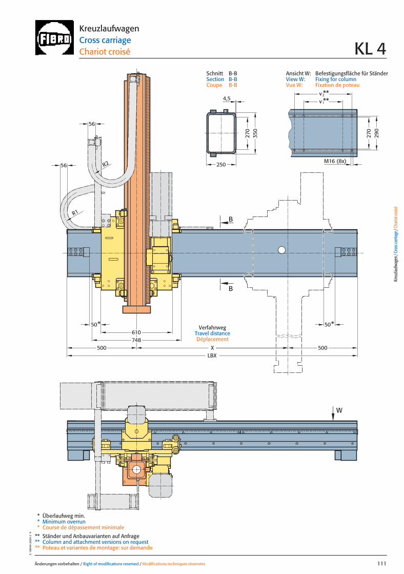
Änderungen vorbehalten / Right of modifications reserved / Modifications techniques réservées 111
5·18
944
·200
4·2
°KreuzlaufwagenCross carriageChariot croisé KL 4
VerfahrwegTravel distanceDéplacement
56
500500 XLBX
610
W
748
50*50*
R1
R2
56
B
B
270
350
250
**2
M16 (8x)
270
290
v
1v **4,5
* Überlaufweg min.* Minimum overrun* Course de dépassement minimale
** Ständer und Anbauvarianten auf Anfrage** Column and attachment versions on request** Poteau et variantes de montage: sur demande
Kreu
zlauf
wage
n / C
ross
carri
age /
Cha
riot c
roisé
Ansicht W: Befestigungsfläche für StänderView W: Fixing for columnVue W: Fixation de poteau
Schnitt B-BSection B-BCoupe B-B
111 27.08.2004 6:42 Uhr Seite 1

Belastungsdaten für zentrische LastLoading data for centric loadDonnées de charge pour charge centrée
System mit größtem HubSystem with greatest strokeSystème avec la plus longue course
MassenschwerpunktCentre of gravityCentre de gravité de la masse
0Z
Z
2Z
A
G zentr
max.
810
910
1010
1060
1160
1310
1410
1560
1810
1960
2160
250
350
450
500
600
750
850
1000
1250
1400
1600
Z
500
Z 2[mm] [mm]
450400 550 600
G zentr[kg]
400 - 600 kg
Änderungen vorbehalten / Right of modifications reserved / Modifications techniques réservées112
5·18
945
·200
4·2
°
KreuzlaufwagenCross carriageChariot croiséKL 4S
Z2 – Z0 Hubmax. / Strokemax. / Coursemax.
Z0 min. 560 mmA ca. / approx. / env. 200 mmZ0 Obere Hublage / Upper lift position /Position de course supérieureZ2 Untere Hublage / Lower lift position / Position de course inférieureZ Hub / Stroke / CourseGzentr. Zentrische Last / Centric load / Charge centréeGzent. max. Maximale zentrische Last / Max. centric load / Charge centrée max.
Belastungen in Abhängigkeit des Vertikalhubes bei zentrischer Last Load as a function of the vertical stroke with centric loadCharge en fonction de la course verticale pour une charge centrée
LastbereichLoad rangePlage de charge
Gzentr.
112 27.08.2004 6:43 Uhr Seite 2
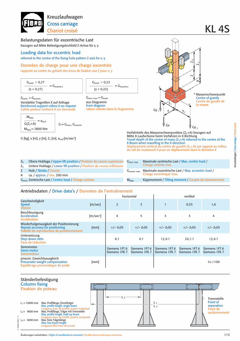
x
0Z
Z
2Z
A
Gy 2
Gy 1
Gx
2y
1y*
*
*
Änderungen vorbehalten / Right of modifications reserved / Modifications techniques réservées 113
5·18
946
·200
3·1
°KreuzlaufwagenCross carriageChariot croisé KL 4S
pneum. GewichtsausgleichPneumatic weight compensation [mm] 1x �100Équilibrage pneumatique de poids
Antriebsdaten / Drive data’s / Données de l’entraînement
GeschwindigkeitSpeed [m/sec] 2 3 1 0,55 1,6Vitesse
horizontal vertikal
Wiederholgenauigkeit der PositionierungRepeat accuracy for positioning [mm] +/– 0,05 +/– 0,05 +/– 0,05 +/– 0,05 +/– 0,05Fidélité de reproduction du positionnement
BeschleunigungAcceleration [m/sec2] 4 5 3 3 4Accélération
Servomotor Siemens 1FT 6 Siemens 1FT 6 Siemens 1FT 6 Siemens 1FT 6 Siemens 1FT 6Servo motor Siemens 1FK 7 Siemens 1FK 7 Siemens 1FK 7 Siemens 1FK 7 Siemens 1FK 7Servomoteur
UntersetzungStep-down ratio 6:1 4:1 12,4:1 24,1:1 12,4:1Taux de réduction
Z0 Obere Hublage / Upper lift position / Position de course supérieureZ2 Untere Hublage / Lower lift position / Position de course inférieureZ Hub / Stroke / CourseA ca. / approx. / env. 200 mmGzentr. Zentrische Last / Centric load / Charge centrée
Gzent. max. Maximale zentrische Last / Max. centric load / Charge centrée max.
Gexzent. max. Maximale exzentrische Last / Max. eccentric load / Charge excentrique max.
Mkipp. Kippmoment / Tilting moment / Couple de renversement
= Gexzentr.y
Belastungsdaten für exzentrische Lastbezogen auf Mitte Befestigungslochbild Z-Achse für x; y
Loading data for eccentric loadreferred to the centre of the fixing hole pattern Z-axis for x; y
Données de charge pour une charge excentréerapporté au centre du gabarit des trous de fixation axe Z pour x; y
Verfahrtiefe des Massenschwerpunktes (Z2+A) bezogen auf Mitte X-Laufschiene beim Verfahren in X-RichtungTravel depth of the centre of mass (Z2+A) referred to the centre of the X Beam when travelling in the X-directionDéplacement vertical du centre de gravité (Z2+A) par rapport au milieudu rail de roulement X pour un déplacement dans la direction X
G [kg], x [m], y [m], Z2 [m], axzul.[m/sec2]
= Gexzentr.x
Gzentr. � 0,27
(x + 0,27)
Gzentr. � 0,22
(y + 0,22)
Gzentr. = Gexzentr.
Verstärkte Tragrollen X auf AnfrageReinforced support rollers X on requestGalets porteur renforcé X sur demande
Gzent. max. = Gzentr.
aus Diagrammfrom diagramvaleur relevée dans le diagramme
* MassenschwerpunktCentre of gravityCentre de gravité dela masse
= axzul.
Mkipp.
G(Z2+A)
Mkipp.= 2800 NmG = Gzent., Gexzentr.
L 3
L 1L 2
Ständerbefestigung Column fixingFixation de poteau
L1 = 10000 mm Max. Profillänge, EinzelträgerMax. profile length, single beam Longueur max. de profilé, poutre individuel
L2 = 9000 mm Max. Profillänge, Träger mit TrennstelleMax. profile length, built-up beam Longueur max. de profilé, poutre composée
L3 = 6000 mm Max. freie TrägerlängeMax. free beam length Longueur libre max. de poutre
TrennstellePoint of separationPoint de sectionnement
Kreu
zlauf
wage
n / C
ross
carri
age /
Cha
riot c
roisé
113 27.08.2004 6:42 Uhr Seite 1
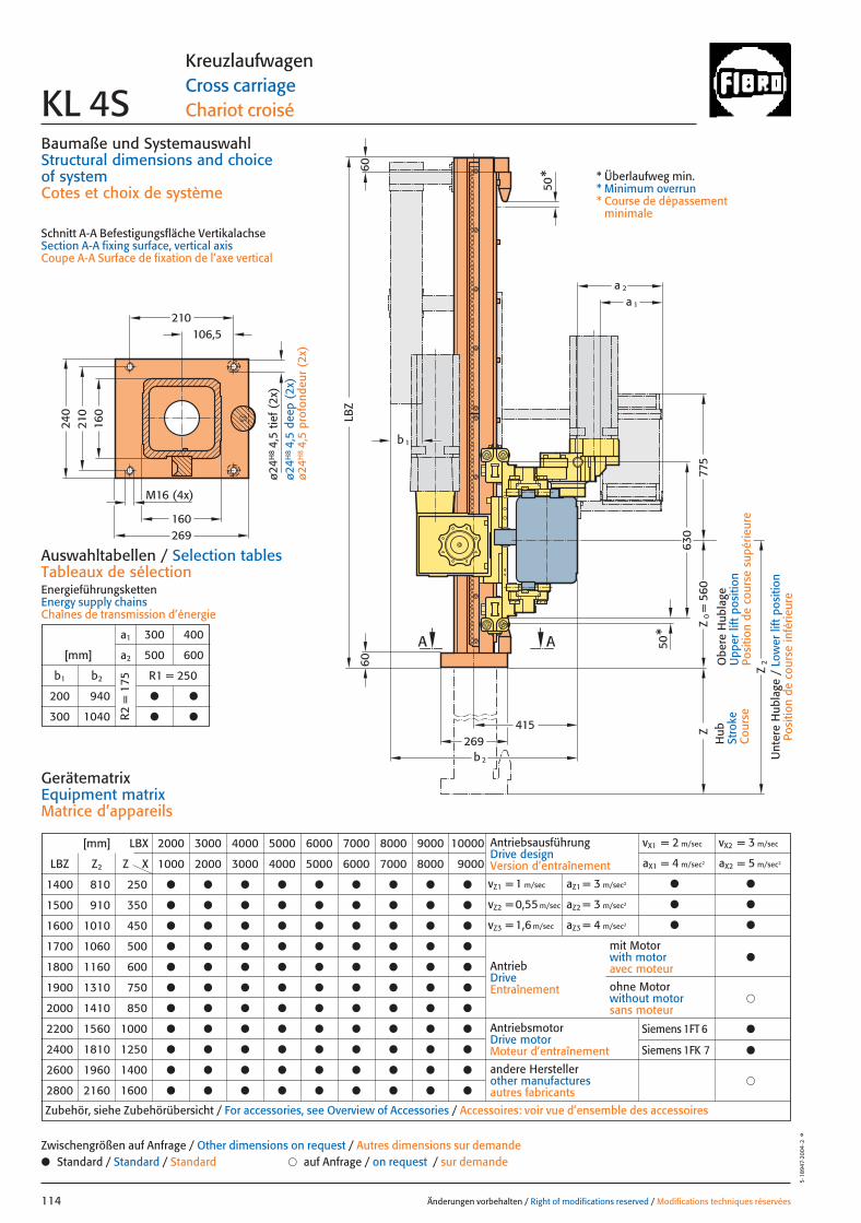
Z2
Z63
077
5
AA
415269
b2
50*
50*
= 5
60Z
0
b 1
6060
LBZ
a 1
a 2
106,5
160
160
269
210
240
210
M16 (4x)
Baumaße und SystemauswahlStructural dimensions and choice of systemCotes et choix de système
Schnitt A-A Befestigungsfläche VertikalachseSection A-A fixing surface, vertical axisCoupe A-A Surface de fixation de l’axe vertical
Änderungen vorbehalten / Right of modifications reserved / Modifications techniques réservées114
5·18
947·
2004
·2°
KreuzlaufwagenCross carriageChariot croiséKL 4S
Hub
Stro
keC
ours
e
Obe
re H
ubla
geU
pper
lift
pos
ition
Posi
tion
de c
ours
e su
périe
ure
Unt
ere
Hub
lage
/ L
ower
lift
pos
ition
Posi
tion
de c
ours
e in
férie
ure
* Überlaufweg min.* Minimum overrun* Course de dépassement
minimale
Auswahltabellen / Selection tablesTableaux de sélectionEnergieführungskettenEnergy supply chainsChaînes de transmission d’énergie
a1 300 400
[mm] a2 500 600
b1 b2 R1 = 250
200 940 ● ●
300 1040 ● ●R2 =
175
[mm] LBX 2000 3000 4000 5000 6000 7000 8000 9000 10000
LBZ Z2 Z X 1000 2000 3000 4000 5000 6000 7000 8000 9000
1400 810 250 ● ● ● ● ● ● ● ● ●
1500 910 350 ● ● ● ● ● ● ● ● ●
1600 1010 450 ● ● ● ● ● ● ● ● ●
1700 1060 500 ● ● ● ● ● ● ● ● ●
1800 1160 600 ● ● ● ● ● ● ● ● ●
1900 1310 750 ● ● ● ● ● ● ● ● ●
2000 1410 850 ● ● ● ● ● ● ● ● ●
2200 1560 1000 ● ● ● ● ● ● ● ● ●
2400 1810 1250 ● ● ● ● ● ● ● ● ●
2600 1960 1400 ● ● ● ● ● ● ● ● ●
2800 2160 1600 ● ● ● ● ● ● ● ● ●
AntriebsausführungDrive designVersion d’entraînement
vX1 = 2 m/sec vX2 = 3 m/sec
aX1 = 4 m/sec2 aX2 = 5 m/sec2
vZ1 = 1 m/sec aZ1 = 3 m/sec2 ● ●
vZ2 = 0,55 m/sec aZ2 = 3 m/sec2 ● ●
vZ3 = 1,6 m/sec aZ3 = 4 m/sec2 ● ●
AntriebDriveEntraînement
AntriebsmotorDrive motorMoteur d’entraînement
�andere Herstellerother manufacturesautres fabricants
Zubehör, siehe Zubehörübersicht / For accessories, see Overview of Accessories / Accessoires: voir vue d’ensemble des accessoires
mit Motorwith motoravec moteur
●
�ohne Motorwithout motorsans moteur
GerätematrixEquipment matrixMatrice d’appareils
● Standard / Standard / Standard � auf Anfrage / on request / sur demandeZwischengrößen auf Anfrage / Other dimensions on request / Autres dimensions sur demande
ø24H
8 4,
5 tie
f (2x
)ø2
4H8 4,
5 de
ep (
2x)
ø24H
8 4,
5 pr
ofon
deur
(2x
)
Siemens 1FT 6 ●
Siemens 1FK 7 ●
114 27.08.2004 6:42 Uhr Seite 2
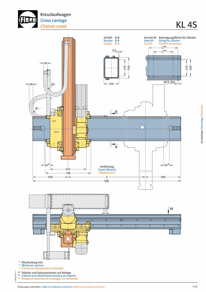
Änderungen vorbehalten / Right of modifications reserved / Modifications techniques réservées 115
5·18
948
·200
4·2
°KreuzlaufwagenCross carriageChariot croisé KL 4S
VerfahrwegTravel distanceDéplacement
W
500500 XLBX
610748
50*50*
56
R1
R256
B
B
270
350
250
**2
M16 (8x)
270
290
v
1v **4,5
* Überlaufweg min.* Minimum overrun* Course de dépassement minimale
** Ständer und Anbauvarianten auf Anfrage** Column and attachment versions on request** Poteau et variantes de montage: sur demande
Kreu
zlauf
wage
n / C
ross
carri
age /
Cha
riot c
roisé
Ansicht W: Befestigungsfläche für StänderView W: Fixing for columnVue W: Fixation de poteau
Schnitt B-BSection B-BCoupe B-B
115 27.08.2004 6:42 Uhr Seite 1
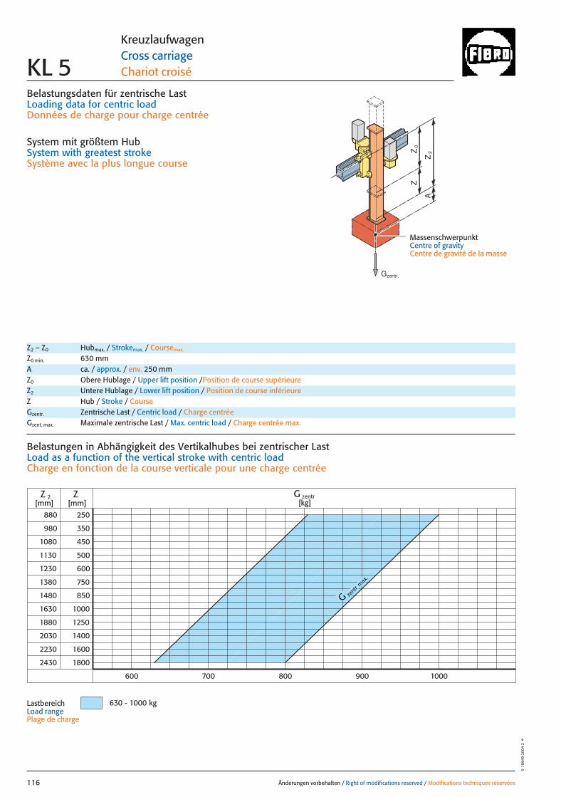
Belastungsdaten für zentrische LastLoading data for centric loadDonnées de charge pour charge centrée
System mit größtem HubSystem with greatest strokeSystème avec la plus longue course
MassenschwerpunktCentre of gravityCentre de gravité de la masse
0Z
Z
2Z
A
880
980
1080
1130
1230
1380
1480
1630
1880
2030
2230
250
350
450
500
600
750
850
1000
1250
1400
1600
ZZ 2[mm] [mm]
800700600 900 1000
2430 1800
G zent
r max
.
G zentr[kg]
630 - 1000 kg
Änderungen vorbehalten / Right of modifications reserved / Modifications techniques réservées116
5·18
949
·200
4·2
°
KreuzlaufwagenCross carriageChariot croiséKL 5
Z2 – Z0 Hubmax. / Strokemax. / Coursemax.
Z0 min. 630 mmA ca. / approx. / env. 250 mmZ0 Obere Hublage / Upper lift position /Position de course supérieureZ2 Untere Hublage / Lower lift position / Position de course inférieureZ Hub / Stroke / CourseGzentr. Zentrische Last / Centric load / Charge centréeGzent. max. Maximale zentrische Last / Max. centric load / Charge centrée max.
Belastungen in Abhängigkeit des Vertikalhubes bei zentrischer Last Load as a function of the vertical stroke with centric loadCharge en fonction de la course verticale pour une charge centrée
LastbereichLoad range Plage de charge
Gzentr.
116 27.08.2004 6:42 Uhr Seite 2
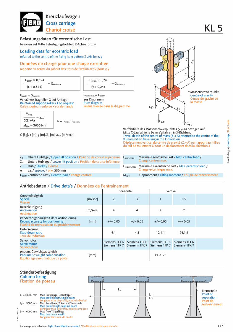
x
0Z
Z
2Z
A
Gy 2
Gy 1
Gx
2y
1y*
*
*
Änderungen vorbehalten / Right of modifications reserved / Modifications techniques réservées 117
5·18
950
·200
3·1
°KreuzlaufwagenCross carriageChariot croisé KL 5
pneum. GewichtsausgleichPneumatic weight compensation [mm] 1x �125Équilibrage pneumatique de poids
Antriebsdaten / Drive data’s / Données de l’entraînement
GeschwindigkeitSpeed [m/sec] 2 3 1 0,5Vitesse
horizontal vertikal
Wiederholgenauigkeit der PositionierungRepeat accuracy for positioning [mm] +/– 0,05 +/– 0,05 +/– 0,05 +/– 0,05Fidélité de reproduction du positionnement
BeschleunigungAcceleration [m/sec2] 4 4 2 2Accélération
Servomotor Siemens 1FT 6 Siemens 1FT 6 Siemens 1FT 6 Siemens 1FT 6Servo motor Siemens 1FK 7 Siemens 1FK 7 Siemens 1FK 7 Siemens 1FK 7Servomoteur
UntersetzungStep-down ratio 6:1 4:1 12,4:1 24,1:1Taux de réduction
Z0 Obere Hublage / Upper lift position / Position de course supérieureZ2 Untere Hublage / Lower lift position / Position de course inférieureZ Hub / Stroke / CourseA ca. / approx. / env. 250 mmGzentr. Zentrische Last / Centric load / Charge centrée
Gzent. max. Maximale zentrische Last / Max. centric load / Charge centrée max.
Gexzent. max. Maximale exzentrische Last / Max. eccentric load / Charge excentrique max.
Mkipp. Kippmoment / Tilting moment / Couple de renversement
= Gexzentr.y
Belastungsdaten für exzentrische Lastbezogen auf Mitte Befestigungslochbild Z-Achse für x; y
Loading data for eccentric loadreferred to the centre of the fixing hole pattern Z-axis for x; y
Données de charge pour une charge excentréerapporté au centre du gabarit des trous de fixation axe Z pour x; y
Verfahrtiefe des Massenschwerpunktes (Z2+A) bezogen auf Mitte X-Laufschiene beim Verfahren in X-RichtungTravel depth of the centre of mass (Z2+A) referred to the centre of the X Beam when travelling in the X-directionDéplacement vertical du centre de gravité (Z2+A) par rapport au milieudu rail de roulement X pour un déplacement dans la direction X
G [kg], x [m], y [m], Z2 [m], axzul.[m/sec2]
= Gexzentr.x
Gzentr. � 0,324
(x + 0,324)
Gzentr. � 0,24
(y + 0,24)
Gzentr. = Gexzentr.
Verstärkte Tragrollen X auf AnfrageReinforced support rollers X on requestGalets porteur renforcé X sur demande
Gzent. max. = Gzentr.
aus Diagrammfrom diagramvaleur relevée dans le diagramme
* MassenschwerpunktCentre of gravityCentre de gravité dela masse
= axzul.
Mkipp.
G(Z2+A)
Mkipp.= 3600 NmG = Gzent., Gexzentr.
L 3
L 1L 2
Ständerbefestigung Column fixingFixation de poteau
L1 = 10000 mm Max. Profillänge, EinzelträgerMax. profile length, single beam Longueur max. de profilé, poutre individuel
L2 = 9000 mm Max. Profillänge, Träger mit TrennstelleMax. profile length, built-up beam Longueur max. de profilé, poutre composée
L3 = 6000 mm Max. freie TrägerlängeMax. free beam length Longueur libre max. de poutre
TrennstellePoint of separationPoint de sectionnement
Kreu
zlauf
wage
n / C
ross
carri
age /
Cha
riot c
roisé
117 27.08.2004 6:42 Uhr Seite 1

158260
260
= 6
30Z
0
LBZ
Z2
Z68
080
0
487
AA
340b2
50*
50*
a 1
a 2
b1
28
2518
0
310
300
M20 (4x)
Baumaße und SystemauswahlStructural dimensions and choice of systemCotes et choix de système
Schnitt A-A Befestigungsfläche VertikalachseSection A-A fixing surface, vertical axisCoupe A-A Surface de fixation de l’axe vertical
Änderungen vorbehalten / Right of modifications reserved / Modifications techniques réservées118
5·18
951·
2004
·2°
KreuzlaufwagenCross carriageChariot croiséKL 5
Hub
Stro
keC
ours
e
Obe
re H
ubla
geU
pper
lift
pos
ition
Posi
tion
de c
ours
e su
périe
ure
Unt
ere
Hub
lage
/ L
ower
lift
pos
ition
Posi
tion
de c
ours
e in
férie
ure
* Überlaufweg min.* Minimum overrun* Course de dépassement
minimale
Auswahltabellen / Selection tablesTableaux de sélectionEnergieführungsketten / Energy supply chainsChaînes de transmission d’énergie
a1 300 400
[mm] a2 500 600
b1 b2 R1 = 250
200 1030 ● ●
300 1130 ● ●R2 =
175
[mm] LBX 2000 3000 4000 5000 6000 7000 8000 9000 10000
LBZ Z2 Z X 800 1800 2800 3800 4800 5800 6800 7800 8800
1500 880 250 ● ● ● ● ● ● ● ● ●
1600 980 350 ● ● ● ● ● ● ● ● ●
1700 1080 450 ● ● ● ● ● ● ● ● ●
1800 1130 500 ● ● ● ● ● ● ● ● ●
1900 1230 600 ● ● ● ● ● ● ● ● ●
2000 1380 750 ● ● ● ● ● ● ● ● ●
2100 1480 850 ● ● ● ● ● ● ● ● ●
2300 1630 1000 ● ● ● ● ● ● ● ● ●
2500 1880 1250 ● ● ● ● ● ● ● ● ●
2700 2030 1400 ● ● ● ● ● ● ● ● ●
2900 2230 1600 ● ● ● ● ● ● ● ● ●
3100 2430 1800 ● ● ● ● ● ● ● ● ●
AntriebsausführungDrive designVersion d’entraînement
vX1 = 2 m/sec vX2 = 3 m/sec
aX1 = 4 m/sec2 aX2 = 4 m/sec2
vZ1 = 1 m/sec aZ1 = 2 m/sec2 ● ●
vZ2 = 0,5 m/sec aZ2 = 2 m/sec2 ● ●
AntriebDriveEntraînement
AntriebsmotorDrive motorMoteur d’entraînement
�andere Herstellerother manufacturesautres fabricants
Zubehör, siehe Zubehörübersicht / For accessories, see Overview of Accessories / Accessoires: voir vue d’ensemble des accessoires
mit Motorwith motoravec moteur
●
�ohne Motorwithout motorsans moteur
GerätematrixEquipment matrixMatrice d’appareils
● Standard / Standard / Standard � auf Anfrage / on request / sur demandeZwischengrößen auf Anfrage / Other dimensions on request / Autres dimensions sur demande
Siemens 1FT 6 ●
Siemens 1FK 7 ●
118 27.08.2004 6:42 Uhr Seite 2

56
600888730
XLBX
W
600
50* 50*
R2
56
R1
B
B
300
320
400
**v **
M16 (8x)
340
320
2
1v4,5
Änderungen vorbehalten / Right of modifications reserved / Modifications techniques réservées 119
5·18
952
·200
4·2
°KreuzlaufwagenCross carriageChariot croisé KL 5
VerfahrwegTravel distanceDéplacement
Kreu
zlauf
wage
n / C
ross
carri
age /
Cha
riot c
roisé
Ansicht W: Befestigungsfläche für StänderView W: Fixing for columnVue W: Fixation de poteau
Schnitt B-BSection B-BCoupe B-B
* Überlaufweg min.* Minimum overrun* Course de dépassement minimale
** Ständer und Anbauvarianten auf Anfrage** Column and attachment versions on request** Poteau et variantes de montage: sur demande
119 27.08.2004 6:39 Uhr Seite 1
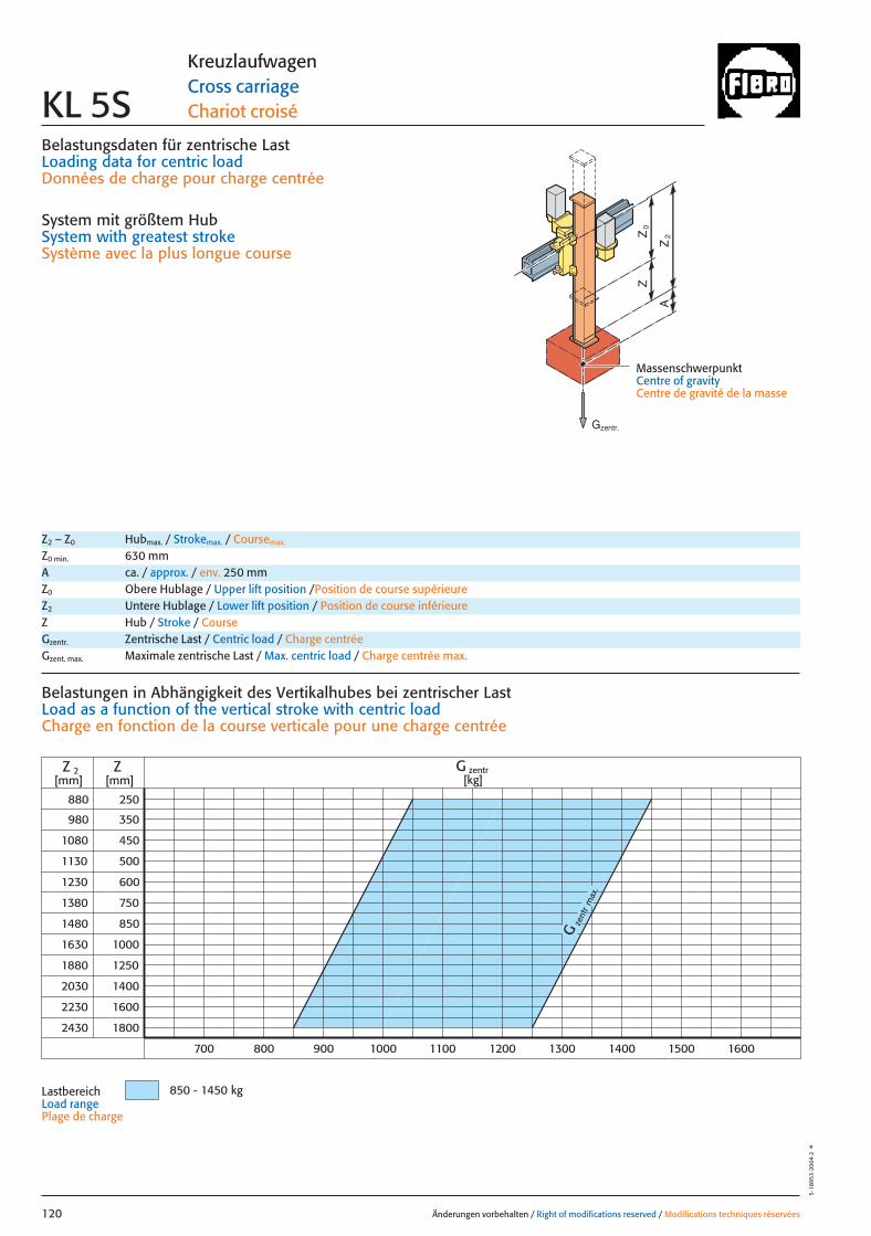
Belastungsdaten für zentrische LastLoading data for centric loadDonnées de charge pour charge centrée
System mit größtem HubSystem with greatest strokeSystème avec la plus longue course
MassenschwerpunktCentre of gravityCentre de gravité de la masse
0Z
Z
2Z
A
880
980
1080
1130
1230
1380
1480
1630
1880
2030
2230
250
350
450
500
600
750
850
1000
1250
1400
1600
ZZ 2[mm] [mm]
900700
2430 1800
Gze
ntr
max
.
800 1000 1100 1200 1300 1400 1500 1600
G zentr[kg]
850 - 1450 kg
Änderungen vorbehalten / Right of modifications reserved / Modifications techniques réservées120
5·18
953
·200
4·2
°
KreuzlaufwagenCross carriageChariot croiséKL 5S
Z2 – Z0 Hubmax. / Strokemax. / Coursemax.
Z0 min. 630 mmA ca. / approx. / env. 250 mmZ0 Obere Hublage / Upper lift position /Position de course supérieureZ2 Untere Hublage / Lower lift position / Position de course inférieureZ Hub / Stroke / CourseGzentr. Zentrische Last / Centric load / Charge centréeGzent. max. Maximale zentrische Last / Max. centric load / Charge centrée max.
Belastungen in Abhängigkeit des Vertikalhubes bei zentrischer Last Load as a function of the vertical stroke with centric loadCharge en fonction de la course verticale pour une charge centrée
Lastbereich Load range Plage de charge
Gzentr.
120 27.08.2004 6:43 Uhr Seite 2
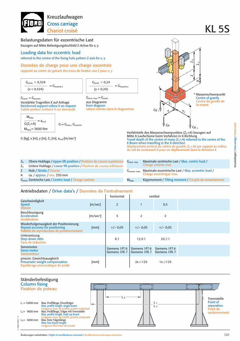
x
0Z
Z
2Z
A
Gy 2
Gy 1
Gx
2y
1y*
*
*
Änderungen vorbehalten / Right of modifications reserved / Modifications techniques réservées 121
5·18
954
·200
3·1
°KreuzlaufwagenCross carriageChariot croisé KL 5S
pneum. GewichtsausgleichPneumatic weight compensation [mm] 2x �125 1x �125Équilibrage pneumatique de poids
Antriebsdaten / Drive data’s / Données de l’entraînement
GeschwindigkeitSpeed [m/sec] 2 1 0,5Vitesse
horizontal vertikal
Wiederholgenauigkeit der PositionierungRepeat accuracy for positioning [mm] +/– 0,05 +/– 0,05 +/– 0,05Fidélité de reproduction du positionnement
BeschleunigungAcceleration [m/sec2] 3 2 2Accélération
Servomotor Siemens 1FT 6 Siemens 1FT 6 Siemens 1FT 6Servo motor Siemens 1FK 7 Siemens 1FK 7 Siemens 1FK 7Servomoteur
UntersetzungStep-down ratio 6:1 12,4:1 24,1:1Taux de réduction
Z0 Obere Hublage / Upper lift position / Position de course supérieureZ2 Untere Hublage / Lower lift position / Position de course inférieureZ Hub / Stroke / CourseA ca. / approx. / env. 250 mmGzentr. Zentrische Last / Centric load / Charge centrée
Gzent. max. Maximale zentrische Last / Max. centric load / Charge centrée max.
Gexzent. max. Maximale exzentrische Last / Max. eccentric load / Charge excentrique max.
Mkipp. Kippmoment / Tilting moment / Couple de renversement
= Gexzentr.y
Belastungsdaten für exzentrische Lastbezogen auf Mitte Befestigungslochbild Z-Achse für x; y
Loading data for eccentric loadreferred to the centre of the fixing hole pattern Z-axis for x; y
Données de charge pour une charge excentréerapporté au centre du gabarit des trous de fixation axe Z pour x; y
Verfahrtiefe des Massenschwerpunktes (Z2+A) bezogen auf Mitte X-Laufschiene beim Verfahren in X-RichtungTravel depth of the centre of mass (Z2+A) referred to the centre of the X Beam when travelling in the X-directionDéplacement vertical du centre de gravité (Z2+A) par rapport au milieudu rail de roulement X pour un déplacement dans la direction X
G [kg], x [m], y [m], Z2 [m], axzul.[m/sec2]
= Gexzentr.x
Gzentr. � 0,324
(x + 0,324)
Gzentr. � 0,24
(y + 0,24)
Gzentr. = Gexzentr.
Verstärkte Tragrollen X auf AnfrageReinforced support rollers X on requestGalets porteur renforcé X sur demande
Gzent. max. = Gzentr.
aus Diagrammfrom diagramvaleur relevée dans le diagramme
* MassenschwerpunktCentre of gravityCentre de gravité dela masse
= axzul.
Mkipp.
G(Z2+A)
Mkipp.= 3600 NmG = Gzent., Gexzentr.
L 3
L 1L 2
Ständerbefestigung Column fixingFixation de poteau
L1 = 10000 mm Max. Profillänge, EinzelträgerMax. profile length, single beam Longueur max. de profilé, poutre individuel
L2 = 9000 mm Max. Profillänge, Träger mit TrennstelleMax. profile length, built-up beam Longueur max. de profilé, poutre composée
L3 = 6000 mm Max. freie TrägerlängeMax. free beam length Longueur libre max. de poutre
TrennstellePoint of separationPoint de sectionnement
Kreu
zlauf
wage
n / C
ross
carri
age /
Cha
riot c
roisé
121 27.08.2004 6:42 Uhr Seite 1
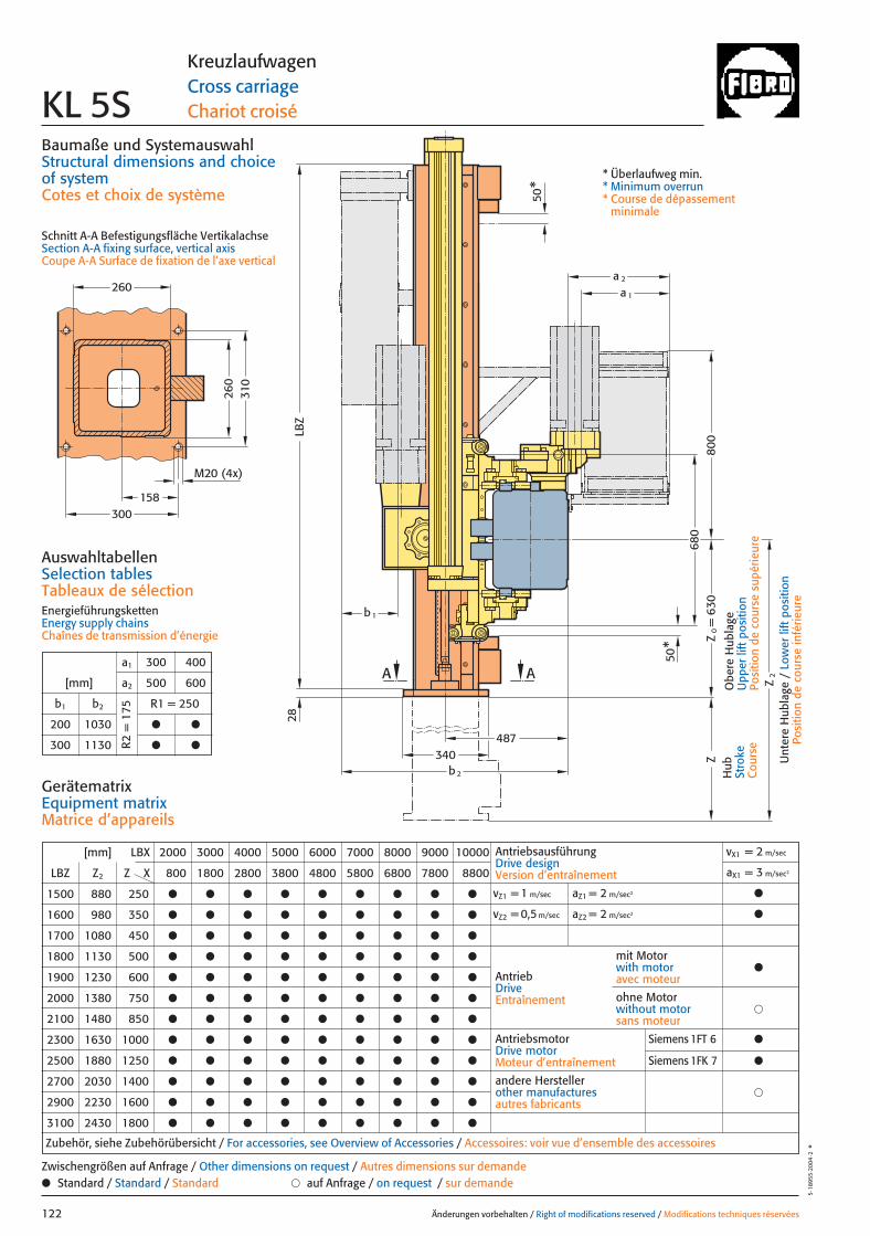
158
b2
680
800
340487
AA
Z2
Z
50*
LBZ
50*
b 1
a 1
a 2
= 6
30Z
0
28260
260
310
300
M20 (4x)
Baumaße und SystemauswahlStructural dimensions and choice of systemCotes et choix de système
Schnitt A-A Befestigungsfläche VertikalachseSection A-A fixing surface, vertical axisCoupe A-A Surface de fixation de l’axe vertical
Änderungen vorbehalten / Right of modifications reserved / Modifications techniques réservées122
5·18
955
·200
4·2
°
KreuzlaufwagenCross carriageChariot croiséKL 5S
Hub
Stro
keC
ours
e
Obe
re H
ubla
geU
pper
lift
pos
ition
Posi
tion
de c
ours
e su
périe
ure
Unt
ere
Hub
lage
/ L
ower
lift
pos
ition
Posi
tion
de c
ours
e in
férie
ure
* Überlaufweg min.* Minimum overrun* Course de dépassement
minimale
AuswahltabellenSelection tablesTableaux de sélectionEnergieführungskettenEnergy supply chainsChaînes de transmission d’énergie
a1 300 400
[mm] a2 500 600
b1 b2 R1 = 250
200 1030 ● ●
300 1130 ● ●R2 =
175
[mm] LBX 2000 3000 4000 5000 6000 7000 8000 9000 10000
LBZ Z2 Z X 800 1800 2800 3800 4800 5800 6800 7800 8800
1500 880 250 ● ● ● ● ● ● ● ● ●
1600 980 350 ● ● ● ● ● ● ● ● ●
1700 1080 450 ● ● ● ● ● ● ● ● ●
1800 1130 500 ● ● ● ● ● ● ● ● ●
1900 1230 600 ● ● ● ● ● ● ● ● ●
2000 1380 750 ● ● ● ● ● ● ● ● ●
2100 1480 850 ● ● ● ● ● ● ● ● ●
2300 1630 1000 ● ● ● ● ● ● ● ● ●
2500 1880 1250 ● ● ● ● ● ● ● ● ●
2700 2030 1400 ● ● ● ● ● ● ● ● ●
2900 2230 1600 ● ● ● ● ● ● ● ● ●
3100 2430 1800 ● ● ● ● ● ● ● ● ●
AntriebsausführungDrive designVersion d’entraînement
vX1 = 2 m/sec
aX1 = 3 m/sec2
vZ1 = 1 m/sec aZ1 = 2 m/sec2 ●
vZ2 = 0,5 m/sec aZ2 = 2 m/sec2 ●
AntriebDriveEntraînement
AntriebsmotorDrive motorMoteur d’entraînement
�andere Herstellerother manufacturesautres fabricants
Zubehör, siehe Zubehörübersicht / For accessories, see Overview of Accessories / Accessoires: voir vue d’ensemble des accessoires
mit Motorwith motoravec moteur
●
�ohne Motorwithout motorsans moteur
GerätematrixEquipment matrixMatrice d’appareils
● Standard / Standard / Standard � auf Anfrage / on request / sur demandeZwischengrößen auf Anfrage / Other dimensions on request / Autres dimensions sur demande
Siemens 1FT 6 ●
Siemens 1FK 7 ●
122 27.08.2004 6:43 Uhr Seite 2
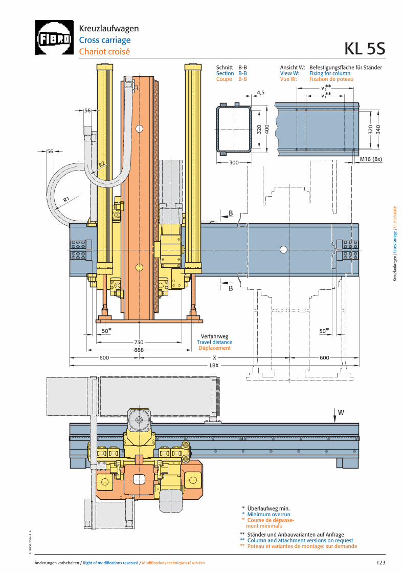
600600
730888
W
XLBX
50* 50*
R2
R1
56
56
B
B
300
320
400
**v **
M16 (8x)
340
320
2
1v4,5
Änderungen vorbehalten / Right of modifications reserved / Modifications techniques réservées 123
5·18
956
·200
4·2
°KreuzlaufwagenCross carriageChariot croisé KL 5S
* Überlaufweg min.* Minimum overrun* Course de dépasse-
ment minimale
** Ständer und Anbauvarianten auf Anfrage** Column and attachment versions on request** Poteau et variantes de montage: sur demande
VerfahrwegTravel distanceDéplacement
Kreu
zlauf
wage
n / C
ross
carri
age /
Cha
riot c
roisé
Ansicht W: Befestigungsfläche für StänderView W: Fixing for columnVue W: Fixation de poteau
Schnitt B-BSection B-BCoupe B-B
123 27.08.2004 6:43 Uhr Seite 1

Änderungen vorbehalten / Right of modifications reserved / Modifications techniques réservées124
5·18
957·
2003
·1°
124 27.08.2004 6:44 Uhr Seite 2
Änderungen vorbehalten / Right of modifications reserved / Modifications techniques réservées 125
5·18
958
·200
3·1
°
Portalroboter TypGantry robote Type
Robot à portique Type KOP
Porta
lrobo
ter /
Gan
try ro
bot /
Rob
ot à
porti
que
125 27.08.2004 7:24 Uhr Seite 1
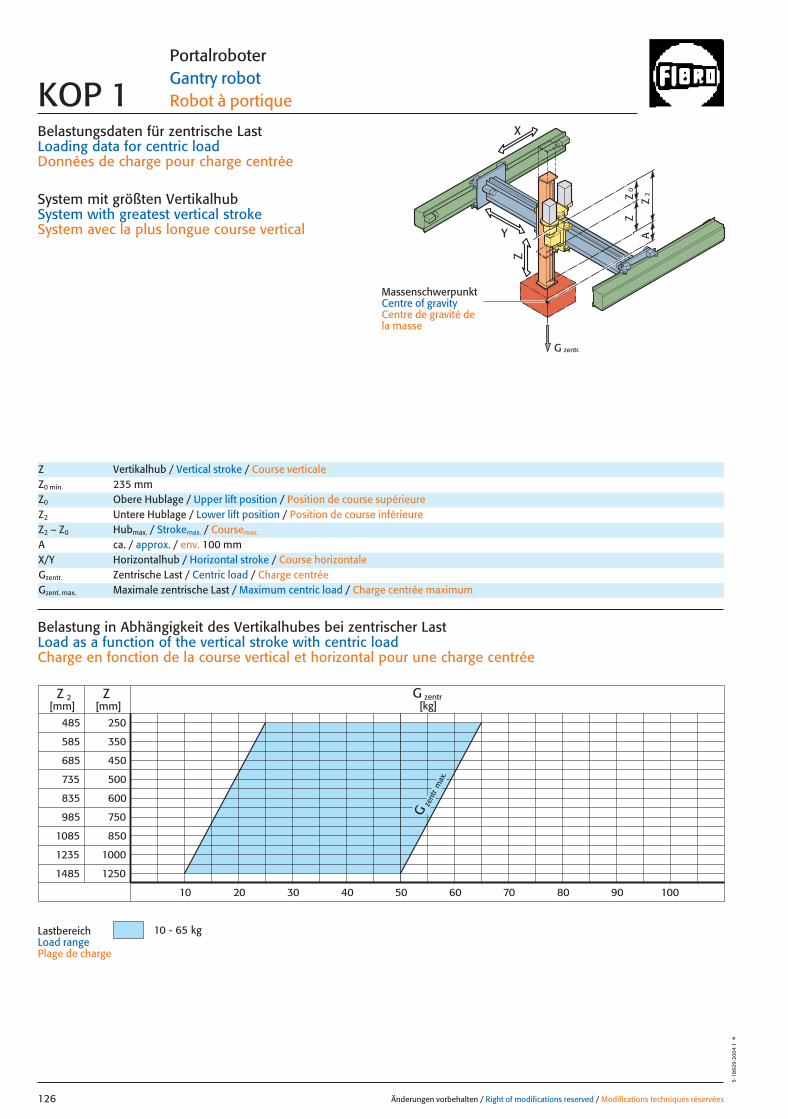
0Z
Z
2Z
A
G zentr.
Z
X
Y
Belastungsdaten für zentrische LastLoading data for centric loadDonnées de charge pour charge centrée
System mit größten VertikalhubSystem with greatest vertical strokeSystem avec la plus longue course vertical
MassenschwerpunktCentre of gravityCentre de gravité dela masse
Gze
ntr
max
.
485
585
985
1085
1235
1485
250
350
450
500
600
1000
1250
ZZ 2[mm] [mm]
750
850
685
735
835
10 - 65 kg
G zentr[kg]
10 20 30 40 50 60 70 80 90 100
Änderungen vorbehalten / Right of modifications reserved / Modifications techniques réservées126
5·18
929
·200
4·1
°
Portalroboter Gantry robot Robot à portique KOP 1
Z Vertikalhub / Vertical stroke / Course verticaleZ0 min. 235 mmZ0 Obere Hublage / Upper lift position / Position de course supérieureZ2 Untere Hublage / Lower lift position / Position de course inférieureZ2 – Z0 Hubmax. / Strokemax. / Coursemax.
A ca. / approx. / env. 100 mm
Gzentr. Zentrische Last / Centric load / Charge centréeGzent. max. Maximale zentrische Last / Maximum centric load / Charge centrée maximum
X/Y Horizontalhub / Horizontal stroke / Course horizontale
Belastung in Abhängigkeit des Vertikalhubes bei zentrischer Last Load as a function of the vertical stroke with centric loadCharge en fonction de la course vertical et horizontal pour une charge centrée
LastbereichLoad range Plage de charge
126 27.08.2004 7:24 Uhr Seite 2
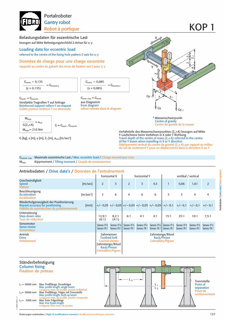
0Z
Z
2Z
A
Z
X
Y
x
Gy 2Gx
2y
1y *Gy 1
*
*
Änderungen vorbehalten / Right of modifications reserved / Modifications techniques réservées 127
5·18
930
·200
4·1
°Portalroboter Gantry robot Robot à portique KOP 1
Gexzent. max. Maximale exzentrische Last / Max. eccentric load / Charge excentrique max.Mkipp. Kippmoment / Tilting moment / Couple de renversement
Antriebsdaten / Drive data’s / Données de l’entraînement
GeschwindigkeitSpeed [m/sec] 2 3 2 3 4,5 1 0,66 1,61 2Vitesse
horizontal X horizontal Y vertikal / vertical
Wiederholgenauigkeit der PositionierungRepeat accuracy for positioning [mm] +/– 0,05 +/– 0,05 +/– 0,05 +/– 0,05 +/– 0,05 +/– 0,1 +/– 0,1 +/– 0,1 +/– 0,1Fidélité de reproduction du positionnement
BeschleunigungAcceleration [m/sec2] 3 6 4 6 6 3 3 4 4Accélération
Servomotor Siemens 1FT 6 Siemens 1FT 6 Siemens 1FT 6 Siemens 1FT 6 Siemens 1FT 6 Siemens 1FT 6 Siemens 1FT 6 Siemens 1FT 6 Siemens 1FT 6Servo motor Siemens 1FK 7 Siemens 1FK 7 Siemens 1FK 7 Siemens 1FK 7 Siemens 1FK 7 Siemens 1FK 7 Siemens 1FK 7 Siemens 1FK 7 Siemens 1FK 7ServomoteurAntrieb Zahnriemen Zahnstange/RitzelDrive Toothed belt Rack/PinionEntraînement Courroie dentée Crémaillère/Pignon
Zahnstange/RitzelRack/Pinion
Crémaillère/Pignon
UntersetzungStep-down ratio 12,9:1 8,2:1 6:1 4:1 4:1 15:1 25:1 10:1 7,5:1Taux de réduction (6:1) (4:1)
= Gexzentr.x
Belastungsdaten für exzentrische Lastbezogen auf Mitte Befestigungslochbild Z-Achse für x; y
Loading data for eccentric loadreferred to the centre of the fixing hole pattern Z-axis for x; y
Données de charge pour une charge excentréerapporté au centre du gabarit des trous de fixation axe Z pour x; y
Verfahrtiefe des Massenschwerpunktes (Z2+A) bezogen auf Mitte Y-Laufschiene beim Verfahren in X oder Y RichtungTravel depth of the centre of mass (Z2+A) referred to the centre of the Y beam when travelling in X or Y directionDéplacement vertical du centre de gravité (Z2+A) par rapport au milieudu rail de roulement Y pour un déplacement dans la direction X ou Y
G [kg], x [m], y [m], Z2 [m], axzul.[m/sec2]
= Gexzentr.y
Gzentr. � 0,135
(y + 0,135)
Gzentr. � 0,085
(x + 0,085)
Gzent. max. = Gzentr.
aus Diagrammfrom diagramvaleur relevée dans le diagram
* MassenschwerpunktCentre of gravityCentre de gravité de la masse
= azul.
Mkipp.
G(Z2+A)
Mkipp.= 210 NmG = Gzent. , Gexzentr.
L 3
L 1L 2
Ständerbefestigung Column fixingFixation de poteau
L1 = 10000 mm Max. Profillänge, EinzelträgerMax. profile length, single beam Longueur max. de profilé, poutre individuel
L2 = 10000 mm Max. Profillänge, Träger mit TrennstelleMax. profile length, built-up beam Longueur max. de profilé, poutre composée
L3 = 5000 mm Max. freie TrägerlängeMax. free beam length Longueur libre max. de poutre
TrennstellePoint of separationPoint de sectionnement
Porta
lrobo
ter /
Gan
try ro
bot /
Rob
ot à
porti
que
Gzentr. = Gexzentr.
Verstärkte Tragrollen Y auf AnfrageReinforced support rollers Y on requestGalets porteur renforcé Y sur demande
127 27.08.2004 7:24 Uhr Seite 1
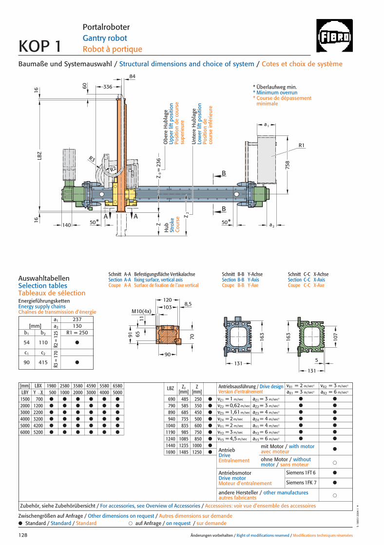
[mm] LBX 1980 2580 3580 4590 5580 6580 LBZ Z2 ZLBY Y X 500 1000 2000 3000 4000 5000 [mm] [mm]
1500 700 ● ● ● ● ● ● 690 485 250 ●
2000 1200 ● ● ● ● ● ● 790 585 350 ●
3000 2200 ● ● ● ● ● ● 890 685 450 ●
4000 3200 ● ● ● ● ● ● 940 735 500 ●
5000 4200 ● ● ● ● ● ● 1040 835 600 ●
6000 5200 ● ● ● ● ● ● 1190 985 750 ●
1240 1085 850 ●
1440 1235 1000 ●
1690 1485 1250 ●
70
11
236
6084
336
a2
M10(4x)
6591
8,5120
107
163
163
131131
B
B
A A
5
103
LBZ
1616
50* 50*
a1
R1
R3
R2
Z
Z2
Z0=
140
758
90
Baumaße und Systemauswahl / Structural dimensions and choice of system / Cotes et choix de système
Schnitt A-A Befestigungsfläche VertikalachseSection A-A fixing surface, vertical axisCoupe A-A Surface de fixation de l’axe vertical
Schnitt B-B Y-AchseSection B-B Y-AxisCoupe B-B Y-Axe
Schnitt C-C X-AchseSection C-C X-AxisCoupe C-C X-Axe
AuswahltabellenSelection tablesTableaux de sélectionEnergieführungskettenEnergy supply chainsChaînes de transmission d’énergie
Änderungen vorbehalten / Right of modifications reserved / Modifications techniques réservées128
5·18
931·
2004
·1°
Portalroboter Gantry robot Robot à portique KOP 1
Hub
Stro
keC
ours
e
Unt
ere
Hub
lage
Low
er li
ft p
ositi
onPo
sitio
n de
co
urse
infé
rieur
e
Obe
re H
ubla
geU
pper
lift
pos
ition
Posi
tion
de c
ours
e su
perie
ure
* Überlaufweg min.* Minimum overrun* Course de dépassement
minimale
a1 237[mm] a2 130
b1 b2 R1 = 250
54 110 ●
c1 c2
90 415 ●
R2 =
125
R3 =
170
Antriebsausführung / Drive design Version d’entraînement
vX1 = 2 m/sec2 vX2 = 3 m/sec2
aX1 = 3 m/sec2 aX2 = 6 m/sec2
vZ1 = 1 m/sec aZ1 = 3 m/sec2 ● ●
vZ2 = 0,62 m/sec aZ2 = 3 m/sec2 ● ●
vZ3 = 1,61 m/sec aZ3 = 4 m/sec2 ● ●
vZ4 = 2 m/sec aZ4 = 4 m/sec2 ● ●
vY1 = 2 m/sec aY1 = 4 m/sec2 ● ●
vY2 = 3 m/sec aY2 = 6 m/sec2 ● ●
vY3 = 4,5 m/sec aY3 = 6 m/sec2 ● ●
AntriebDriveEntraînement
AntriebsmotorDrive motorMoteur d’entraînement
Siemens 1FT 6 ●
Siemens 1FK 7 ●
�andere Hersteller / other manufacturesautres fabricants
Zubehör, siehe Zubehörübersicht / For accessories, see Overview of Accessories / Accessoires: voir vue d’ensemble des accessoires
mit Motor / with motoravec moteur ●
�ohne Motor / withoutmotor / sans moteur
● Standard / Standard / Standard � auf Anfrage / on request / sur demandeZwischengrößen auf Anfrage / Other dimensions on request / Autres dimensions sur demande
128 27.08.2004 7:24 Uhr Seite 2
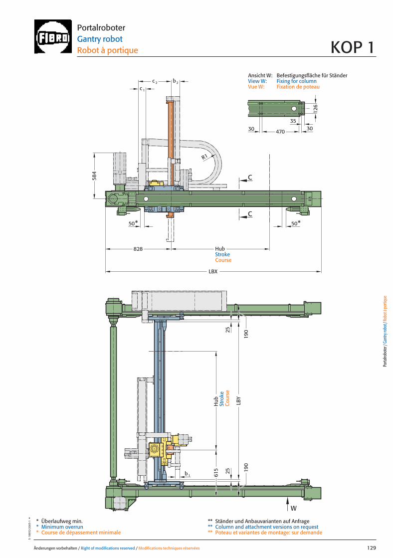
Änderungen vorbehalten / Right of modifications reserved / Modifications techniques réservées 129
5·18
932·
2003
·1°
PortalroboterGantry robot Robot à portique KOP 1
* Überlaufweg min.* Minimum overrun* Course de dépassement minimale
** Ständer und Anbauvarianten auf Anfrage** Column and attachment versions on request** Poteau et variantes de montage: sur demande
Ansicht W: Befestigungsfläche für StänderView W: Fixing for columnVue W: Fixation de poteau
Porta
lrobo
ter /
Gan
try ro
bot /
Rob
ot à
porti
que
615
LBY
LBX
b2
126
470
W
C
C
30 30
c 2
c 1
R1
b1
50* 50*
584
35
82819
019
0
2525
Hub
Stro
keC
ours
e
HubStrokeCourse
129 27.08.2004 7:25 Uhr Seite 1
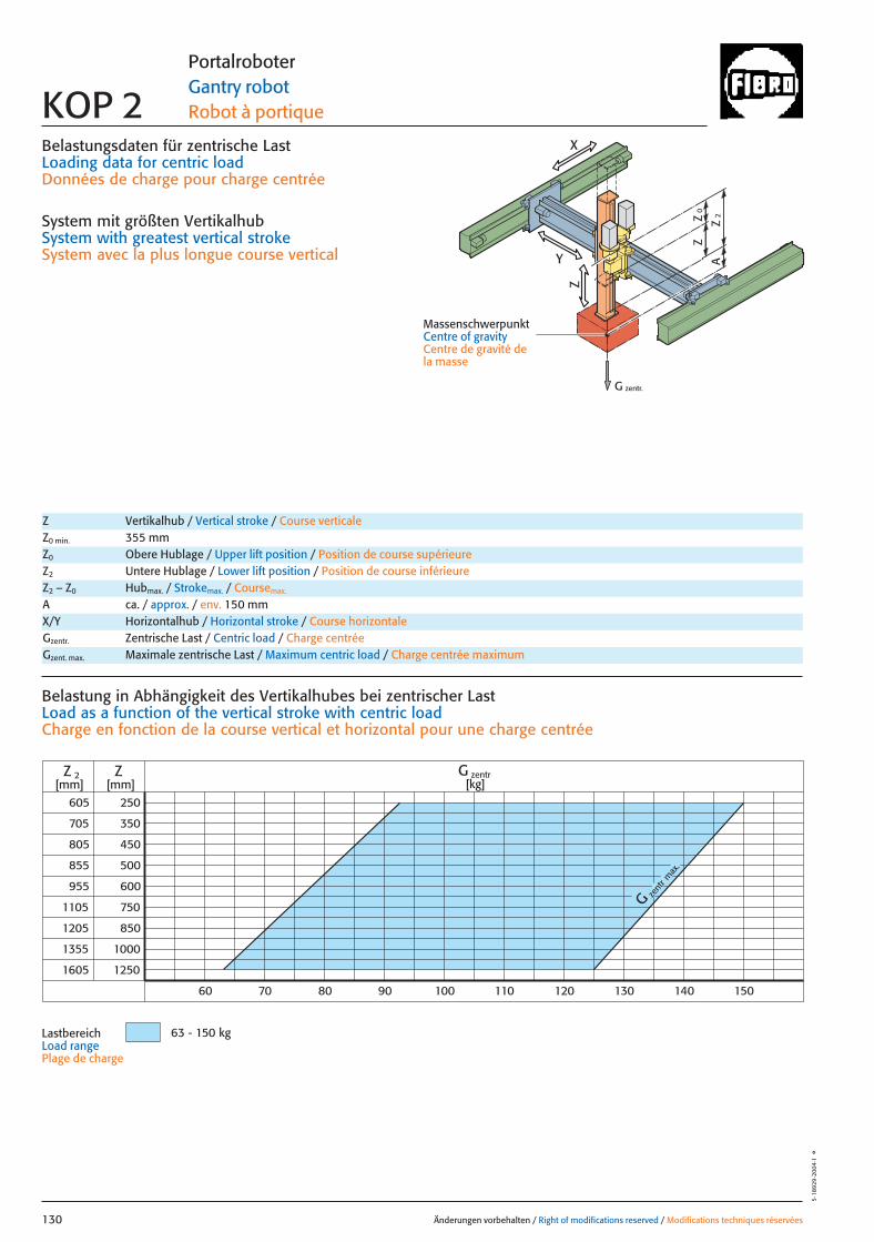
0Z
Z
2Z
A
G zentr.
Z
X
Y
Belastungsdaten für zentrische LastLoading data for centric loadDonnées de charge pour charge centrée
System mit größten VertikalhubSystem with greatest vertical strokeSystem avec la plus longue course vertical
MassenschwerpunktCentre of gravityCentre de gravité dela masse
G zent
r max
.
605
705
1105
1205
1355
1605
250
350
450
500
600
1000
1250
ZZ 2[mm] [mm]
70 80 90 150
750
850
805
855
955
60 140130120110100
G zentr[kg]
63 - 150 kg
Änderungen vorbehalten / Right of modifications reserved / Modifications techniques réservées130
5·18
929
·200
4·1
°
Portalroboter Gantry robot Robot à portique KOP 2
Z Vertikalhub / Vertical stroke / Course verticaleZ0 min. 355 mmZ0 Obere Hublage / Upper lift position / Position de course supérieureZ2 Untere Hublage / Lower lift position / Position de course inférieureZ2 – Z0 Hubmax. / Strokemax. / Coursemax.
A ca. / approx. / env. 150 mm
Gzentr. Zentrische Last / Centric load / Charge centréeGzent. max. Maximale zentrische Last / Maximum centric load / Charge centrée maximum
X/Y Horizontalhub / Horizontal stroke / Course horizontale
Belastung in Abhängigkeit des Vertikalhubes bei zentrischer Last Load as a function of the vertical stroke with centric loadCharge en fonction de la course vertical et horizontal pour une charge centrée
LastbereichLoad range Plage de charge
130 27.08.2004 7:25 Uhr Seite 2

0Z
Z
2Z
A
Z
X
Y
x
Gy 2Gx
2y
1y *Gy 1
*
*
Änderungen vorbehalten / Right of modifications reserved / Modifications techniques réservées 131
5·18
930
·200
4·1
°Portalroboter Gantry robot Robot à portique KOP 2
Gexzent. max. Maximale exzentrische Last / Max. eccentric load / Charge excentrique max.Mkipp. Kippmoment / Tilting moment / Couple de renversement
= Gexzentr.x
Belastungsdaten für exzentrische Lastbezogen auf Mitte Befestigungslochbild Z-Achse für x; y
Loading data for eccentric loadreferred to the centre of the fixing hole pattern Z-axis for x; y
Données de charge pour une charge excentréerapporté au centre du gabarit des trous de fixation axe Z pour x; y
Verfahrtiefe des Massenschwerpunktes (Z2+A) bezogen auf Mitte Y-Laufschiene beim Verfahren in X oder Y RichtungTravel depth of the centre of mass (Z2+A) referred to the centre of the Y beam when travelling in X or Y directionDéplacement vertical du centre de gravité (Z2+A) par rapport au milieudu rail de roulement Y pour un déplacement dans la direction X ou Y
G [kg], x [m], y [m], Z2 [m], axzul.[m/sec2]
= Gexzentr.y
Gzentr. � 0,175
(y + 0,175)
Gzentr. � 0,131
(x + 0,131)
Gzent. max. = Gzentr.
aus Diagrammfrom diagramvaleur relevée dans le diagram
* MassenschwerpunktCentre of gravityCentre de gravité de la masse
= azul.
Mkipp.
G(Z2+A)
Mkipp.= 350 NmG = Gzent., Gexzentr.
L 3
L 1L 2
Ständerbefestigung Column fixingFixation de poteau
L1 = 10000 mm Max. Profillänge, EinzelträgerMax. profile length, single beam Longueur max. de profilé, poutre individuel
L2 = 10000 mm Max. Profillänge, Träger mit TrennstelleMax. profile length, built-up beam Longueur max. de profilé, poutre composée
L3 = 5000 mm Max. freie TrägerlängeMax. free beam length Longueur libre max. de poutre
TrennstellePoint of separationPoint de sectionnement
Porta
lrobo
ter /
Gan
try ro
bot /
Rob
ot à
porti
que
Gzentr. = Gexzentr.
Verstärkte Tragrollen Y auf AnfrageReinforced support rollers Y on requestGalets porteur renforcé Y sur demande
Antriebsdaten / Drive data’s / Données de l’entraînement
GeschwindigkeitSpeed [m/sec] 2 3 2 3 4,5 1 0,62 1,61 2Vitesse
horizontal X horizontal Y vertikal / vertical
Wiederholgenauigkeit der PositionierungRepeat accuracy for positioning [mm] +/– 0,05 +/– 0,05 +/– 0,05 +/– 0,05 +/– 0,05 +/– 0,05 +/– 0,05 +/– 0,05 +/– 0,05Fidélité de reproduction du positionnement
BeschleunigungAcceleration [m/sec2] 3 6 4 6 6 3 3 4 4Accélération
Servomotor Siemens 1FT 6 Siemens 1FT 6 Siemens 1FT 6 Siemens 1FT 6 Siemens 1FT 6 Siemens 1FT 6 Siemens 1FT 6 Siemens 1FT 6 Siemens 1FT 6Servo motor Siemens 1FK 7 Siemens 1FK 7 Siemens 1FK 7 Siemens 1FK 7 Siemens 1FK 7 Siemens 1FK 7 Siemens 1FK 7 Siemens 1FK 7 Siemens 1FK 7ServomoteurAntrieb Zahnriemen Zahnstange/RitzelDrive Toothed belt Rack/PinionEntraînement Courroie dentée Crémaillère/Pignon
Zahnstange/RitzelRack/Pinion
Crémaillère/Pignon
UntersetzungStep-down ratio 12,9:1 8,2:1 6:1 4:1 4:1 10,2:1 16,1:1 10,2:1 7,5:1Taux de réduction (6:1) (4:1)
131 27.08.2004 7:25 Uhr Seite 1
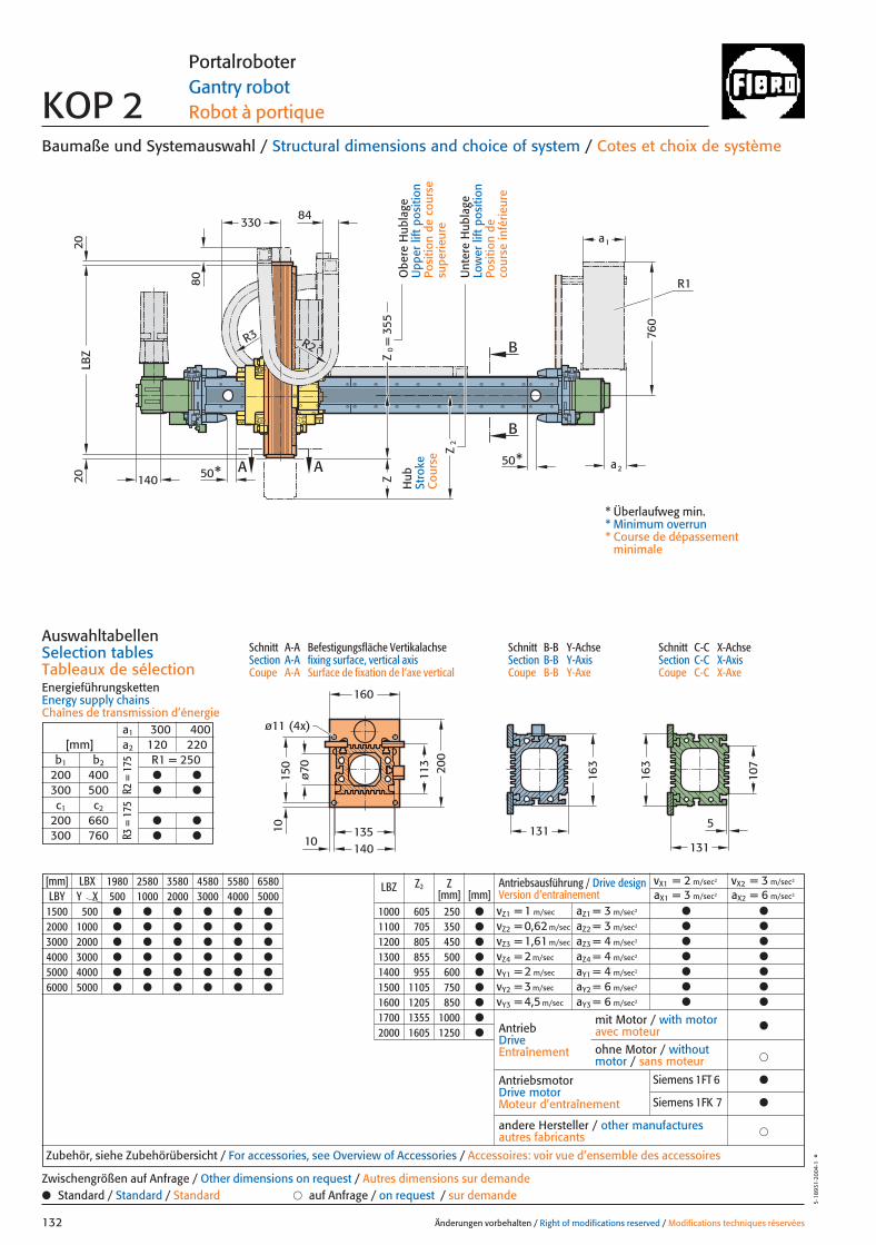
355
ø11 (4x)
A A
LBZ Z
0=
Z2
Z
10140
ø70 200
150
160
10
B
B
2020
50*50*
131
163
330
80
84
R2R3
140a2
a1
760
R1
135
113
107
131
163
5
[mm] LBX 1980 2580 3580 4580 5580 6580 LBZ Z2 ZLBY Y X 500 1000 2000 3000 4000 5000 [mm] [mm]
1500 500 ● ● ● ● ● ● 1000 605 250 ●
2000 1000 ● ● ● ● ● ● 1100 705 350 ●
3000 2000 ● ● ● ● ● ● 1200 805 450 ●
4000 3000 ● ● ● ● ● ● 1300 855 500 ●
5000 4000 ● ● ● ● ● ● 1400 955 600 ●
6000 5000 ● ● ● ● ● ● 1500 1105 750 ●
1600 1205 850 ●
1700 1355 1000 ●
2000 1605 1250 ●
Baumaße und Systemauswahl / Structural dimensions and choice of system / Cotes et choix de système
AuswahltabellenSelection tablesTableaux de sélectionEnergieführungskettenEnergy supply chainsChaînes de transmission d’énergie
Änderungen vorbehalten / Right of modifications reserved / Modifications techniques réservées132
5·18
931·
2004
·1°
Portalroboter Gantry robot Robot à portique KOP 2
Hub
Stro
keC
ours
e
Unt
ere
Hub
lage
Low
er li
ft p
ositi
onPo
sitio
n de
co
urse
infé
rieur
e
Obe
re H
ubla
geU
pper
lift
pos
ition
Posi
tion
de c
ours
e su
perie
ure
* Überlaufweg min.* Minimum overrun* Course de dépassement
minimale
a1 300 400[mm] a2 120 220
b1 b2 R1 = 250 200 400 ● ●
300 500 ● ●
c1 c2
200 660 ● ●
300 760 ● ●
R2 =
175
R3 =
175
Antriebsausführung / Drive design Version d’entraînement
vX1 = 2 m/sec2 vX2 = 3 m/sec2
aX1 = 3 m/sec2 aX2 = 6 m/sec2
vZ1 = 1 m/sec aZ1 = 3 m/sec2 ● ●
vZ2 = 0,62 m/sec aZ2 = 3 m/sec2 ● ●
vZ3 = 1,61 m/sec aZ3 = 4 m/sec2 ● ●
vZ4 = 2 m/sec aZ4 = 4 m/sec2 ● ●
vY1 = 2 m/sec aY1 = 4 m/sec2 ● ●
vY2 = 3 m/sec aY2 = 6 m/sec2 ● ●
vY3 = 4,5 m/sec aY3 = 6 m/sec2 ● ●
Zubehör, siehe Zubehörübersicht / For accessories, see Overview of Accessories / Accessoires: voir vue d’ensemble des accessoires
● Standard / Standard / Standard � auf Anfrage / on request / sur demandeZwischengrößen auf Anfrage / Other dimensions on request / Autres dimensions sur demande
Schnitt A-A Befestigungsfläche VertikalachseSection A-A fixing surface, vertical axisCoupe A-A Surface de fixation de l’axe vertical
Schnitt B-B Y-AchseSection B-B Y-AxisCoupe B-B Y-Axe
Schnitt C-C X-AchseSection C-C X-AxisCoupe C-C X-Axe
AntriebDriveEntraînement
AntriebsmotorDrive motorMoteur d’entraînement
Siemens 1FT 6 ●
Siemens 1FK 7 ●
�andere Hersteller / other manufacturesautres fabricants
mit Motor / with motoravec moteur ●
�ohne Motor / withoutmotor / sans moteur
132 27.08.2004 7:25 Uhr Seite 2
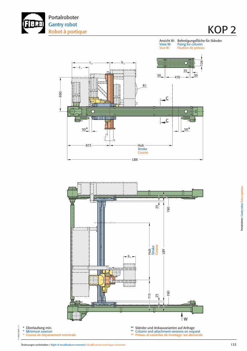
126
470
LBY
LBX
50* 50*
C
C
W
c 2
c 1
b2
690
873
R1
b1
715
190
190
303035
2525
Änderungen vorbehalten / Right of modifications reserved / Modifications techniques réservées 133
5·18
932·
2003
·1°
PortalroboterGantry robot Robot à portique KOP 2
Ansicht W: Befestigungsfläche für StänderView W: Fixing for columnVue W: Fixation de poteau
Porta
lrobo
ter /
Gan
try ro
bot /
Rob
ot à
porti
que
Hub
Stro
keC
ours
e
HubStrokeCourse
* Überlaufweg min.* Minimum overrun* Course de dépassement minimale
** Ständer und Anbauvarianten auf Anfrage** Column and attachment versions on request** Poteau et variantes de montage: sur demande
133 27.08.2004 7:25 Uhr Seite 1
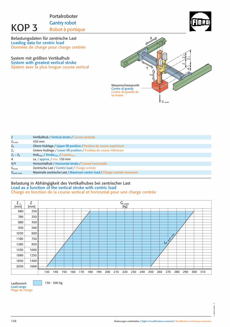
0Z
Z
2Z
A
G zentr.
Z
X
Y
Belastungsdaten für zentrische LastLoading data for centric loadDonnées de charge pour charge centrée
System mit größten VertikalhubSystem with greatest vertical strokeSystem avec la plus longue course vertical
MassenschwerpunktCentre of gravityCentre de gravité dela masse
zent
r
G
max
.
680
780
880
930
1030
1180
1280
1430
1680
1830
2030
250
350
450
500
600
750
850
1000
1250
1400
1600
Z
130 140 150 160 170 180 190 200 210 220 230 240 250 260 270 280 290 300 310
Z 2 G zentr[kg][mm] [mm]
130 - 300 kg
Änderungen vorbehalten / Right of modifications reserved / Modifications techniques réservées134
5·18
929
·200
4·1
°
Portalroboter Gantry robot Robot à portique KOP 3
Z Vertikalhub / Vertical stroke / Course verticaleZ0 min. 430 mmZ0 Obere Hublage / Upper lift position / Position de course supérieureZ2 Untere Hublage / Lower lift position / Position de course inférieureZ2 – Z0 Hubmax. / Strokemax. / Coursemax.
A ca. / approx. / env. 150 mm
Gzentr. Zentrische Last / Centric load / Charge centréeGzent. max. Maximale zentrische Last / Maximum centric load / Charge centrée maximum
X/Y Horizontalhub / Horizontal stroke / Course horizontale
Belastung in Abhängigkeit des Vertikalhubes bei zentrischer Last Load as a function of the vertical stroke with centric loadCharge en fonction de la course vertical et horizontal pour une charge centrée
LastbereichLoad range Plage de charge
134 27.08.2004 7:25 Uhr Seite 2

0Z
Z
2Z
A
Z
X
Y
x
Gy 2Gx
2y
1y *Gy 1
*
*
Änderungen vorbehalten / Right of modifications reserved / Modifications techniques réservées 135
5·18
930
·200
4·1
°Portalroboter Gantry robot Robot à portique KOP 3
Gexzent. max. Maximale exzentrische Last / Max. eccentric load / Charge excentrique max.Mkipp. Kippmoment / Tilting moment / Couple de renversement
Antriebsdaten / Drive data’s / Données de l’entraînement
GeschwindigkeitSpeed [m/sec] 2 3 2 3 1 0,62 1,61Vitesse
horizontal X horizontal Y vertikal / vertical
Wiederholgenauigkeit der PositionierungRepeat accuracy for positioning [mm] +/– 0,05 +/– 0,05 +/– 0,05 +/– 0,05 +/– 0,05 +/– 0,05 +/– 0,05Fidélité de reproduction du positionnement
BeschleunigungAcceleration [m/sec2] 3 4 4 6 3 3 4Accélération
Servomotor Siemens 1FT 6 Siemens 1FT 6 Siemens 1FT 6 Siemens 1FT 6 Siemens 1FT 6 Siemens 1FT 6 Siemens 1FT 6Servo motor Siemens 1FK 7 Siemens 1FK 7 Siemens 1FK 7 Siemens 1FK 7 Siemens 1FK 7 Siemens 1FK 7 Siemens 1FK 7ServomoteurPneumatischer GewichtsausgleichPneumatic weight compensation 1� �80Équilibrage pneumatique de poids
UntersetzungStep-down ratio 5:1 4:1 6:1 4:1 10,2:1 16,1:1 10,2:1Taux de réduction
= Gexzentr.x
Belastungsdaten für exzentrische Lastbezogen auf Mitte Befestigungslochbild Z-Achse für x; y
Loading data for eccentric loadreferred to the centre of the fixing hole pattern Z-axis for x; y
Données de charge pour une charge excentréerapporté au centre du gabarit des trous de fixation axe Z pour x; y
Verfahrtiefe des Massenschwerpunktes (Z2+A) bezogen auf Mitte Y-Laufschiene beim Verfahren in X oder Y RichtungTravel depth of the centre of mass (Z2+A) referred to the centre of the Y beam when travelling in X or Y directionDéplacement vertical du centre de gravité (Z2+A) par rapport au milieu du rail de roulement Y pour un déplacement dans la direction X ou Y
G [kg], x [m], y [m], Z2 [m], axzul.[m/sec2]
= Gexzentr.y
Gzentr. � 0,225
(y + 0,225)
Gzentr. � 0,135
(x + 0,135)
Gzent. max. = Gzentr.
aus Diagrammfrom diagramvaleur relevée dans le diagram
* MassenschwerpunktCentre of gravityCentre de gravité de la masse
= azul.
Mkipp.
G(Z2+A)
Mkipp.= 700 NmG = Gzent., Gexzentr.
L 3
L 1L 2
Ständerbefestigung Column fixingFixation de poteau
L1 = 10000 mm Max. Profillänge, EinzelträgerMax. profile length, single beam Longueur max. de profilé, poutre individuel
L2 = 10000 mm Max. Profillänge, Träger mit TrennstelleMax. profile length, built-up beam Longueur max. de profilé, poutre composée
L3 = 6000 mm Max. freie TrägerlängeMax. free beam length Longueur libre max. de poutre
TrennstellePoint of separationPoint de sectionnement
Porta
lrobo
ter /
Gan
try ro
bot /
Rob
ot à
porti
que
Gzentr. = Gexzentr.
Verstärkte Tragrollen Y auf AnfrageReinforced support rollers Y on requestGalets porteur renforcé Y sur demande
135 27.08.2004 7:25 Uhr Seite 1
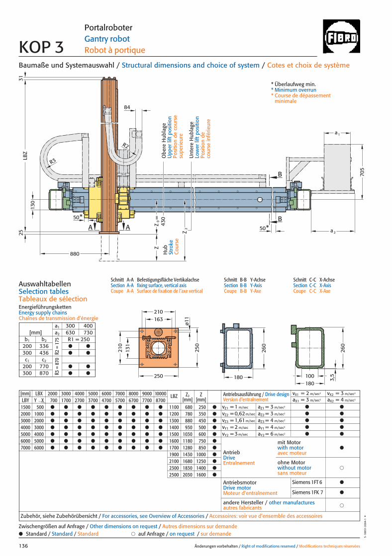
130
a
880
50A AB
B
ø11
250
210
250
210
LBZ
25
Z0=
Z2
Z
50*
*
84
705
R3
R2
430
a 2
1
163
131
180
260
180
260
100
3,5
31
[mm] LBX 2000 3000 4000 5000 6000 7000 8000 9000 10000 LBZ Z2 ZLBY Y X 700 1700 2700 3700 4700 5700 6700 7700 8700 [mm] [mm]
1500 500 ● ● ● ● ● ● ● ● ● 1100 680 250 ●
2000 1000 ● ● ● ● ● ● ● ● ● 1200 780 350 ●
3000 2000 ● ● ● ● ● ● ● ● ● 1300 880 450 ●
4000 3000 ● ● ● ● ● ● ● ● ● 1400 930 500 ●
5000 4000 ● ● ● ● ● ● ● ● ● 1500 1030 600 ●
6000 5000 ● ● ● ● ● ● ● ● ● 1600 1180 750 ●
7000 6000 ● ● ● ● ● ● ● ● ● 1700 1280 850 ●
1900 1430 1000 ●
2100 1680 1250 ●
2300 1830 1400 ●
2500 2030 1600 ●
Baumaße und Systemauswahl / Structural dimensions and choice of system / Cotes et choix de système
Schnitt A-A Befestigungsfläche VertikalachseSection A-A fixing surface, vertical axisCoupe A-A Surface de fixation de l’axe vertical
Schnitt B-B Y-AchseSection B-B Y-AxisCoupe B-B Y-Axe
Schnitt C-C X-AchseSection C-C X-AxisCoupe C-C X-Axe
AuswahltabellenSelection tablesTableaux de sélectionEnergieführungskettenEnergy supply chainsChaînes de transmission d’énergie
Änderungen vorbehalten / Right of modifications reserved / Modifications techniques réservées136
5·18
931·
2004
·1°
Portalroboter Gantry robot Robot à portique KOP 3
Hub
Stro
keC
ours
e
Unt
ere
Hub
lage
Low
er li
ft p
ositi
onPo
sitio
n de
co
urse
infé
rieur
e
Obe
re H
ubla
geU
pper
lift
pos
ition
Posi
tion
de c
ours
e su
perie
ure
* Überlaufweg min.* Minimum overrun* Course de dépassement
minimale
a1 300 400[mm] a2 630 730
b1 b2 R1 = 250200 336 ● ●
300 436 ● ●
c1 c2
200 770 ● ●
300 870 ● ●
R2 =
175
R3 =
870
Antriebsausführung / Drive design Version d’entraînement
vX1 = 2 m/sec2 vX2 = 3 m/sec2
aX1 = 3 m/sec2 aX2 = 4 m/sec2
vZ1 = 1 m/sec aZ1 = 3 m/sec2 ● ●
vZ2 = 0,62 m/sec aZ2 = 3 m/sec2 ● ●
vZ3 = 1,61 m/sec aZ3 = 4 m/sec2 ● ●
vY1 = 2 m/sec aY1 = 4 m/sec2 ● ●
vY2 = 3 m/sec aY2 = 6 m/sec2 ● ●
AntriebDriveEntraînement
AntriebsmotorDrive motorMoteur d’entraînement
�andere Hersteller / other manufacturesautres fabricants
Zubehör, siehe Zubehörübersicht / For accessories, see Overview of Accessories / Accessoires: voir vue d’ensemble des accessoires
mit Motorwith motoravec moteur
●
�ohne Motorwithout motorsans moteur
● Standard / Standard / Standard � auf Anfrage / on request / sur demandeZwischengrößen auf Anfrage / Other dimensions on request / Autres dimensions sur demande
Siemens 1FT 6 ●
Siemens 1FK 7 ●
136 27.08.2004 7:25 Uhr Seite 2
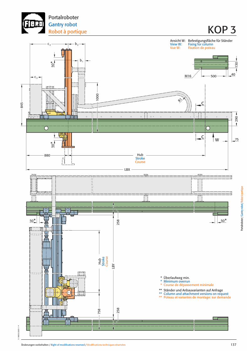
130
500
75
c
b
LBX
50* 50*
50*
50*
C
C
W
LBY
c 2 b2
1
2
845
880
R1
290
758
258
258
40M16
1000
Änderungen vorbehalten / Right of modifications reserved / Modifications techniques réservées 137
5·18
932·
2003
·1°
PortalroboterGantry robot Robot à portique KOP 3
* Überlaufweg min.* Minimum overrun* Course de dépassement minimale
** Ständer und Anbauvarianten auf Anfrage** Column and attachment versions on request** Poteau et variantes de montage: sur demande
Ansicht W: Befestigungsfläche für StänderView W: Fixing for columnVue W: Fixation de poteau
Porta
lrobo
ter /
Gan
try ro
bot /
Rob
ot à
porti
que
Hub
Stro
keC
ours
e
HubStrokeCourse
137 27.08.2004 7:26 Uhr Seite 1
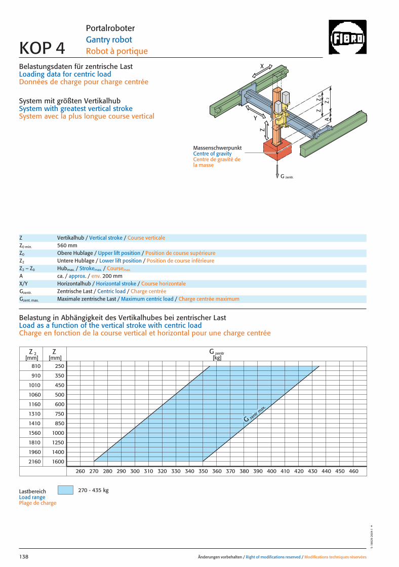
0Z
Z
2Z
A
G zentr.
Z
X
Y
Belastungsdaten für zentrische LastLoading data for centric loadDonnées de charge pour charge centrée
System mit größten VertikalhubSystem with greatest vertical strokeSystem avec la plus longue course vertical
MassenschwerpunktCentre of gravityCentre de gravité dela masse
G zentr
max.
810
910
1010
1060
1160
1310
1410
1560
1810
1960
2160
250
350
450
500
600
750
850
1000
1250
1400
1600
Z
360
Z 2[mm] [mm]
350340330320310300290280270260 370 380 390 400 410 420 430 440 450 460
G zentr[kg]
270 - 435 kg
Änderungen vorbehalten / Right of modifications reserved / Modifications techniques réservées138
5·18
929
·200
4·1
°
Portalroboter Gantry robot Robot à portique KOP 4
Z Vertikalhub / Vertical stroke / Course verticaleZ0 min. 560 mmZ0 Obere Hublage / Upper lift position / Position de course supérieureZ2 Untere Hublage / Lower lift position / Position de course inférieureZ2 – Z0 Hubmax. / Strokemax. / Coursemax.
A ca. / approx. / env. 200 mm
Gzentr. Zentrische Last / Centric load / Charge centréeGzent. max. Maximale zentrische Last / Maximum centric load / Charge centrée maximum
X/Y Horizontalhub / Horizontal stroke / Course horizontale
Belastung in Abhängigkeit des Vertikalhubes bei zentrischer Last Load as a function of the vertical stroke with centric loadCharge en fonction de la course vertical et horizontal pour une charge centrée
LastbereichLoad range Plage de charge
138 27.08.2004 7:26 Uhr Seite 2

0Z
Z
2Z
A
Z
X
Y
x
Gy 2Gx
2y
1y *Gy 1
*
*
Änderungen vorbehalten / Right of modifications reserved / Modifications techniques réservées 139
5·18
930
·200
4·1
°Portalroboter Gantry robot Robot à portique KOP 4
Gexzent. max. Maximale exzentrische Last / Max. eccentric load / Charge excentrique max.Mkipp. Kippmoment / Tilting moment / Couple de renversement
Antriebsdaten / Drive data’s / Données de l’entraînement
GeschwindigkeitSpeed [m/sec] 2 3 2 3 0,82 0,52 1,6Vitesse
horizontal X horizontal Y vertikal / vertical
Wiederholgenauigkeit der PositionierungRepeat accuracy for positioning [mm] +/– 0,05 +/– 0,05 +/– 0,05 +/– 0,05 +/– 0,05 +/– 0,05 +/– 0,05Fidélité de reproduction du positionnement
BeschleunigungAcceleration [m/sec2] 3 4 4 4 3 3 4Accélération
Servomotor Siemens 1FT 6 Siemens 1FT 6 Siemens 1FT 6 Siemens 1FT 6 Siemens 1FT 6 Siemens 1FT 6 Siemens 1FT 6Servo motor Siemens 1FK 7 Siemens 1FK 7 Siemens 1FK 7 Siemens 1FK 7 Siemens 1FK 7 Siemens 1FK 7 Siemens 1FK 7ServomoteurPneumatischer GewichtsausgleichPneumatic weight compensation 1� �100Équilibrage pneumatique de poids
UntersetzungStep-down ratio 5:1 4:1 6:1 4:1 16,1:1 25,5:1 8,2:1Taux de réduction
= Gexzentr.x
Belastungsdaten für exzentrische Lastbezogen auf Mitte Befestigungslochbild Z-Achse für x; y
Loading data for eccentric loadreferred to the centre of the fixing hole pattern Z-axis for x; y
Données de charge pour une charge excentréerapporté au centre du gabarit des trous de fixation axe Z pour x; y
Verfahrtiefe des Massenschwerpunktes (Z2+A) bezogen auf Mitte Y-Laufschiene beim Verfahren in X oder Y RichtungTravel depth of the centre of mass (Z2+A) referred to the centre of the Y beam when travelling in X or Y directionDéplacement vertical du centre de gravité (Z2+A) par rapport au milieu du rail de roulement Y pour un déplacement dans la direction X ou Y
G [kg], x [m], y [m], Z2 [m], axzul.[m/sec2]
= Gexzentr.y
Gzentr. � 0,27
(y + 0,27)
Gzentr. � 0,22
(x + 0,22)
Gzent. max. = Gzentr.
aus Diagrammfrom diagramvaleur relevée dans le diagram
* MassenschwerpunktCentre of gravityCentre de gravité de la masse
= azul.
Mkipp.
G(Z2+A)
Mkipp.= 1400 NmG = Gzent., Gexzentr.
L 3
L 1L 2
Ständerbefestigung Column fixingFixation de poteau
L1 = 10000 mm Max. Profillänge, EinzelträgerMax. profile length, single beam Longueur max. de profilé, poutre individuel
L2 = 10000 mm Max. Profillänge, Träger mit TrennstelleMax. profile length, built-up beam Longueur max. de profilé, poutre composée
L3 = 6000 mm Max. freie TrägerlängeMax. free beam length Longueur libre max. de poutre
TrennstellePoint of separationPoint de sectionnement
Porta
lrobo
ter /
Gan
try ro
bot /
Rob
ot à
porti
que
Gzentr. = Gexzentr.
Verstärkte Tragrollen Y auf AnfrageReinforced support rollers Y on requestGalets porteur renforcé y sur demande
139 27.08.2004 7:26 Uhr Seite 1
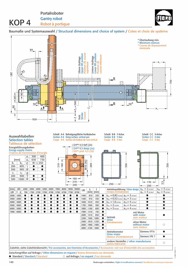
[mm] LBX 2000 3000 4000 5000 6000 7000 8000 9000 10000 LBZ Z2 ZLBY Y X 700 1700 2700 3700 4700 5700 6700 7700 8700 [mm] [mm]
2000 1000 ● ● ● ● ● ● ● ● ● 1400 810 250 ●
3000 2000 ● ● ● ● ● ● ● ● ● 1500 910 350 ●
4000 3000 ● ● ● ● ● ● ● ● ● 1600 1010 450 ●
5000 4000 ● ● ● ● ● ● ● ● ● 1700 1060 500 ●
6000 5000 ● ● ● ● ● ● ● ● ● 1800 1160 600 ●
7000 6000 ● ● ● ● ● ● ● ● ● 1900 1310 750 ●
2000 1410 850 ●
2200 1560 1000 ●
2400 1810 1250 ●
2600 1960 1400 ●
2800 2160 1600 ●
Z
LBZ
Z
A A 0= Z2
B
B
240210
269
210
M16
(4x
)
50* 50*
R3R2
265
750
a 2
a1
250
160
160
350
250170
3,5
350
560
84
920
90
60
Baumaße und Systemauswahl / Structural dimensions and choice of system / Cotes et choix de système
Schnitt A-A Befestigungsfläche VertikalachseSection A-A fixing surface, vertical axisCoupe A-A Surface de fixation de l’axe vertical
Schnitt B-B Y-AchseSection B-B Y-AxisCoupe B-B Y-Axe
Schnitt C-C X-AchseSection C-C X-AxisCoupe C-C X-Axe
AuswahltabellenSelection tablesTableaux de sélectionEnergieführungskettenEnergy supply chainsChaînes de transmission d’énergie
Änderungen vorbehalten / Right of modifications reserved / Modifications techniques réservées140
5·18
931·
2004
·1°
Portalroboter Gantry robot Robot à portique KOP 4
Hub
Stro
keC
ours
e
Unt
ere
Hub
lage
Low
er li
ft p
ositi
onPo
sitio
n de
co
urse
infé
rieur
e
Obe
re H
ubla
geU
pper
lift
pos
ition
Posi
tion
de c
ours
e su
perie
ure
* Überlaufweg min.* Minimum overrun* Course de dépassement
minimale
a1 300 400[mm] a2 630 730
b1 b2 R1 = 250200 895 ● ●
300 995 ● ●
c1 c2
200 900 ● ●
300 1000 ● ●
R2 =
175
R3 =
250
�24H8 4,5 tief (2x)�24H8 4,5 deep (2x)�24H8 prof. 4,5 (2x)
Antriebsausführung / Drive design Version d’entraînement
vX1 = 2 m/sec2 vX2 = 3 m/sec2
aX1 = 3 m/sec2 aX2 = 4 m/sec2
vZ1 = 0,82 m/sec aZ1 = 3 m/sec2 ● ●
vZ2 = 0,52 m/sec aZ2 = 3 m/sec2 ● ●
vZ3 = 1,6 m/sec aZ3 = 4 m/sec2 ● ●
vY1 = 2 m/sec aY1 = 4 m/sec2 ● ●
vY2 = 3 m/sec aY2 = 4 m/sec2 ● ●
AntriebDriveEntraînement
AntriebsmotorDrive motorMoteur d’entraînement
�andere Hersteller / other manufacturesautres fabricants
Zubehör, siehe Zubehörübersicht / For accessories, see Overview of Accessories / Accessoires: voir vue d’ensemble des accessoires
mit Motorwith motoravec moteur
●
�ohne Motorwithout motorsans moteur
● Standard / Standard / Standard � auf Anfrage / on request / sur demandeZwischengrößen auf Anfrage / Other dimensions on request / Autres dimensions sur demande
Siemens 1FT 6 ●
Siemens 1FK 7 ●
140 27.08.2004 7:26 Uhr Seite 2

200
1000
LBX
50*
50*
50*50*
C
C
W
LBY
b1
c 2 b2
c 1
335
R1
828
328
328
M16 500 40
960
1110
Änderungen vorbehalten / Right of modifications reserved / Modifications techniques réservées 141
5·18
932·
2003
·1°
PortalroboterGantry robot Robot à portique KOP 4
* Überlaufweg min.* Minimum overrun* Course de dépassement minimale
** Ständer und Anbauvarianten auf Anfrage** Column and attachment versions on request** Poteau et variantes de montage: sur demande
Ansicht W: Befestigungsfläche für StänderView W: Fixing for columnVue W: Fixation de poteau
Porta
lrobo
ter /
Gan
try ro
bot /
Rob
ot à
porti
que
Hub
Stro
keC
ours
e
HubStrokeCourse
141 27.08.2004 7:26 Uhr Seite 1
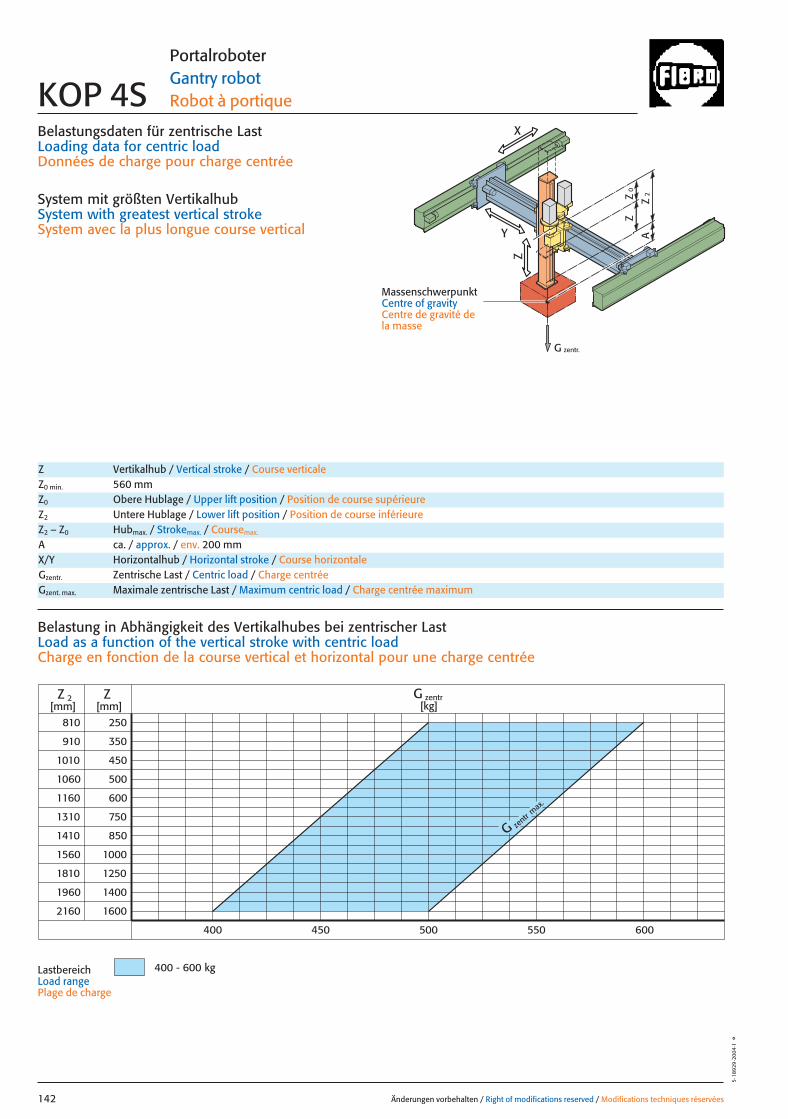
0Z
Z
2Z
A
G zentr.
Z
X
Y
Belastungsdaten für zentrische LastLoading data for centric loadDonnées de charge pour charge centrée
System mit größten VertikalhubSystem with greatest vertical strokeSystem avec la plus longue course vertical
MassenschwerpunktCentre of gravityCentre de gravité dela masse
G zentr
max.
810
910
1010
1060
1160
1310
1410
1560
1810
1960
2160
250
350
450
500
600
750
850
1000
1250
1400
1600
Z
500
Z 2[mm] [mm]
450400 550 600
G zentr[kg]
400 - 600 kg
Änderungen vorbehalten / Right of modifications reserved / Modifications techniques réservées142
5·18
929
·200
4·1
°
Portalroboter Gantry robot Robot à portique KOP 4S
Z Vertikalhub / Vertical stroke / Course verticaleZ0 min. 560 mmZ0 Obere Hublage / Upper lift position / Position de course supérieureZ2 Untere Hublage / Lower lift position / Position de course inférieureZ2 – Z0 Hubmax. / Strokemax. / Coursemax.
A ca. / approx. / env. 200 mm
Gzentr. Zentrische Last / Centric load / Charge centréeGzent. max. Maximale zentrische Last / Maximum centric load / Charge centrée maximum
X/Y Horizontalhub / Horizontal stroke / Course horizontale
Belastung in Abhängigkeit des Vertikalhubes bei zentrischer Last Load as a function of the vertical stroke with centric loadCharge en fonction de la course vertical et horizontal pour une charge centrée
LastbereichLoad range Plage de charge
142 27.08.2004 7:26 Uhr Seite 2
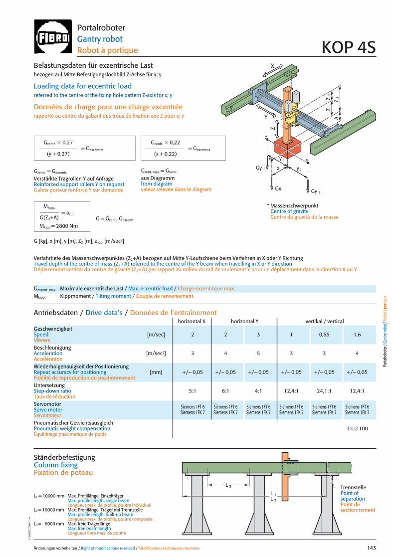
0Z
Z
2Z
A
Z
X
Y
x
Gy 2Gx
2y
1y *Gy 1
*
*
Änderungen vorbehalten / Right of modifications reserved / Modifications techniques réservées 143
5·18
930
·200
4·1
°Portalroboter Gantry robot Robot à portique KOP 4S
Gexzent. max. Maximale exzentrische Last / Max. eccentric load / Charge excentrique max.Mkipp. Kippmoment / Tilting moment / Couple de renversement
Antriebsdaten / Drive data’s / Données de l’entraînement
GeschwindigkeitSpeed [m/sec] 2 2 3 1 0,55 1,6Vitesse
horizontal X horizontal Y vertikal / vertical
Wiederholgenauigkeit der PositionierungRepeat accuracy for positioning [mm] +/– 0,05 +/– 0,05 +/– 0,05 +/– 0,05 +/– 0,05 +/– 0,05Fidélité de reproduction du positionnement
BeschleunigungAcceleration [m/sec2] 3 4 5 3 3 4Accélération
Servomotor Siemens 1FT 6 Siemens 1FT 6 Siemens 1FT 6 Siemens 1FT 6 Siemens 1FT 6 Siemens 1FT 6Servo motor Siemens 1FK 7 Siemens 1FK 7 Siemens 1FK 7 Siemens 1FK 7 Siemens 1FK 7 Siemens 1FK 7ServomoteurPneumatischer GewichtsausgleichPneumatic weight compensation 1� �100Équilibrage pneumatique de poids
UntersetzungStep-down ratio 5:1 6:1 4:1 12,4:1 24,1:1 12,4:1Taux de réduction
= Gexzentr.x
Belastungsdaten für exzentrische Lastbezogen auf Mitte Befestigungslochbild Z-Achse für x; y
Loading data for eccentric loadreferred to the centre of the fixing hole pattern Z-axis for x; y
Données de charge pour une charge excentréerapporté au centre du gabarit des trous de fixation axe Z pour x; y
Verfahrtiefe des Massenschwerpunktes (Z2+A) bezogen auf Mitte Y-Laufschiene beim Verfahren in X oder Y RichtungTravel depth of the centre of mass (Z2+A) referred to the centre of the Y beam when travelling in X or Y directionDéplacement vertical du centre de gravité (Z2+A) par rapport au milieu du rail de roulement Y pour un déplacement dans la direction X ou Y
G [kg], x [m], y [m], Z2 [m], axzul.[m/sec2]
= Gexzentr.y
Gzentr. � 0,27
(y + 0,27)
Gzentr. � 0,22
(x + 0,22)
Gzent. max. = Gzentr.
aus Diagrammfrom diagramvaleur relevée dans le diagram
* MassenschwerpunktCentre of gravityCentre de gravité de la masse
= azul.
Mkipp.
G(Z2+A)
Mkipp.= 2800 NmG = Gzent., Gexzentr.
L 3
L 1L 2
Ständerbefestigung Column fixingFixation de poteau
L1 = 10000 mm Max. Profillänge, EinzelträgerMax. profile length, single beam Longueur max. de profilé, poutre individuel
L2 = 10000 mm Max. Profillänge, Träger mit TrennstelleMax. profile length, built-up beam Longueur max. de profilé, poutre composée
L3 = 6000 mm Max. freie TrägerlängeMax. free beam length Longueur libre max. de poutre
TrennstellePoint of separationPoint de sectionnement
Porta
lrobo
ter /
Gan
try ro
bot /
Rob
ot à
porti
que
Gzentr. = Gexzentr.
Verstärkte Tragrollen Y auf AnfrageReinforced support rollers Y on requestGalets porteur renforcé Y sur demande
143 27.08.2004 7:26 Uhr Seite 1
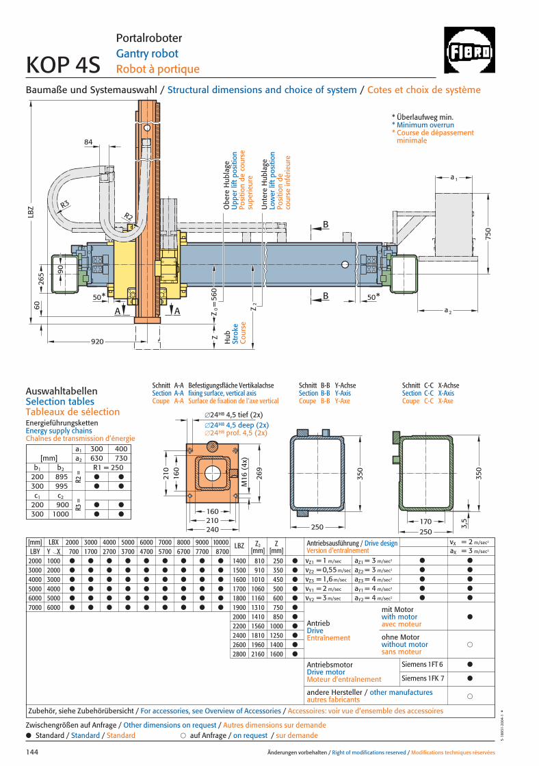
[mm] LBX 2000 3000 4000 5000 6000 7000 8000 9000 10000 LBZ Z2 ZLBY Y X 700 1700 2700 3700 4700 5700 6700 7700 8700 [mm] [mm]
2000 1000 ● ● ● ● ● ● ● ● ● 1400 810 250 ●
3000 2000 ● ● ● ● ● ● ● ● ● 1500 910 350 ●
4000 3000 ● ● ● ● ● ● ● ● ● 1600 1010 450 ●
5000 4000 ● ● ● ● ● ● ● ● ● 1700 1060 500 ●
6000 5000 ● ● ● ● ● ● ● ● ● 1800 1160 600 ●
7000 6000 ● ● ● ● ● ● ● ● ● 1900 1310 750 ●
2000 1410 850 ●
2200 1560 1000 ●
2400 1810 1250 ●
2600 1960 1400 ●
2800 2160 1600 ●
A A
B
BZ
Z2
50*50*
R3R2
265
Z0=
560
750
a 2
a1
250
350
250170
3,5
350
84
920
90
240210
269
210
M16
(4x
)
160
160
LBZ
60
Baumaße und Systemauswahl / Structural dimensions and choice of system / Cotes et choix de système
Schnitt A-A Befestigungsfläche VertikalachseSection A-A fixing surface, vertical axisCoupe A-A Surface de fixation de l’axe vertical
Schnitt B-B Y-AchseSection B-B Y-AxisCoupe B-B Y-Axe
Schnitt C-C X-AchseSection C-C X-AxisCoupe C-C X-Axe
AuswahltabellenSelection tablesTableaux de sélectionEnergieführungskettenEnergy supply chainsChaînes de transmission d’énergie
Änderungen vorbehalten / Right of modifications reserved / Modifications techniques réservées144
5·18
931·
2004
·1°
Portalroboter Gantry robot Robot à portique KOP 4S
Hub
Stro
keC
ours
e
Unt
ere
Hub
lage
Low
er li
ft p
ositi
onPo
sitio
n de
co
urse
infé
rieur
e
Obe
re H
ubla
geU
pper
lift
pos
ition
Posi
tion
de c
ours
e su
perie
ure
* Überlaufweg min.* Minimum overrun* Course de dépassement
minimale
a1 300 400[mm] a2 630 730
b1 b2 R1 = 250200 895 ● ●
300 995 ● ●
c1 c2
200 900 ● ●
300 1000 ● ●
R2 =
R3
=
�24H8 4,5 tief (2x)�24H8 4,5 deep (2x)�24H8 prof. 4,5 (2x)
Antriebsausführung / Drive design Version d’entraînement
vX = 2 m/sec2
aX = 3 m/sec2
vZ1 = 1 m/sec aZ1 = 3 m/sec2 ● ●
vZ2 = 0,55 m/sec aZ2 = 3 m/sec2 ● ●
vZ3 = 1,6 m/sec aZ3 = 4 m/sec2 ● ●
vY1 = 2 m/sec aY1 = 4 m/sec2 ● ●
vY2 = 3 m/sec aY2 = 4 m/sec2 ● ●
AntriebDriveEntraînement
AntriebsmotorDrive motorMoteur d’entraînement
�andere Hersteller / other manufacturesautres fabricants
Zubehör, siehe Zubehörübersicht / For accessories, see Overview of Accessories / Accessoires: voir vue d’ensemble des accessoires
mit Motorwith motoravec moteur
●
�ohne Motorwithout motorsans moteur
● Standard / Standard / Standard � auf Anfrage / on request / sur demandeZwischengrößen auf Anfrage / Other dimensions on request / Autres dimensions sur demande
Siemens 1FT 6 ●
Siemens 1FK 7 ●
144 27.08.2004 7:26 Uhr Seite 2
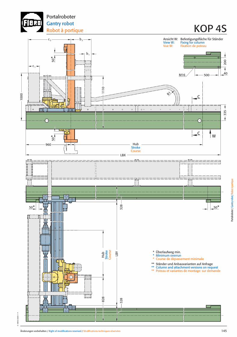
LBX
50*
50*
50* 50*
C
C
W
LBY
1000
b1
c 2 b2
c 1
335
R1
828
328
328
200
M16 500 40
960
1110
Änderungen vorbehalten / Right of modifications reserved / Modifications techniques réservées 145
5·18
932·
2003
·1°
PortalroboterGantry robot Robot à portique KOP 4S
* Überlaufweg min.* Minimum overrun* Course de dépassement minimale
** Ständer und Anbauvarianten auf Anfrage** Column and attachment versions on request** Poteau et variantes de montage: sur demande
Ansicht W: Befestigungsfläche für StänderView W: Fixing for columnVue W: Fixation de poteau
Porta
lrobo
ter /
Gan
try ro
bot /
Rob
ot à
porti
que
Hub
Stro
keC
ours
e
HubStrokeCourse
145 27.08.2004 7:27 Uhr Seite 1
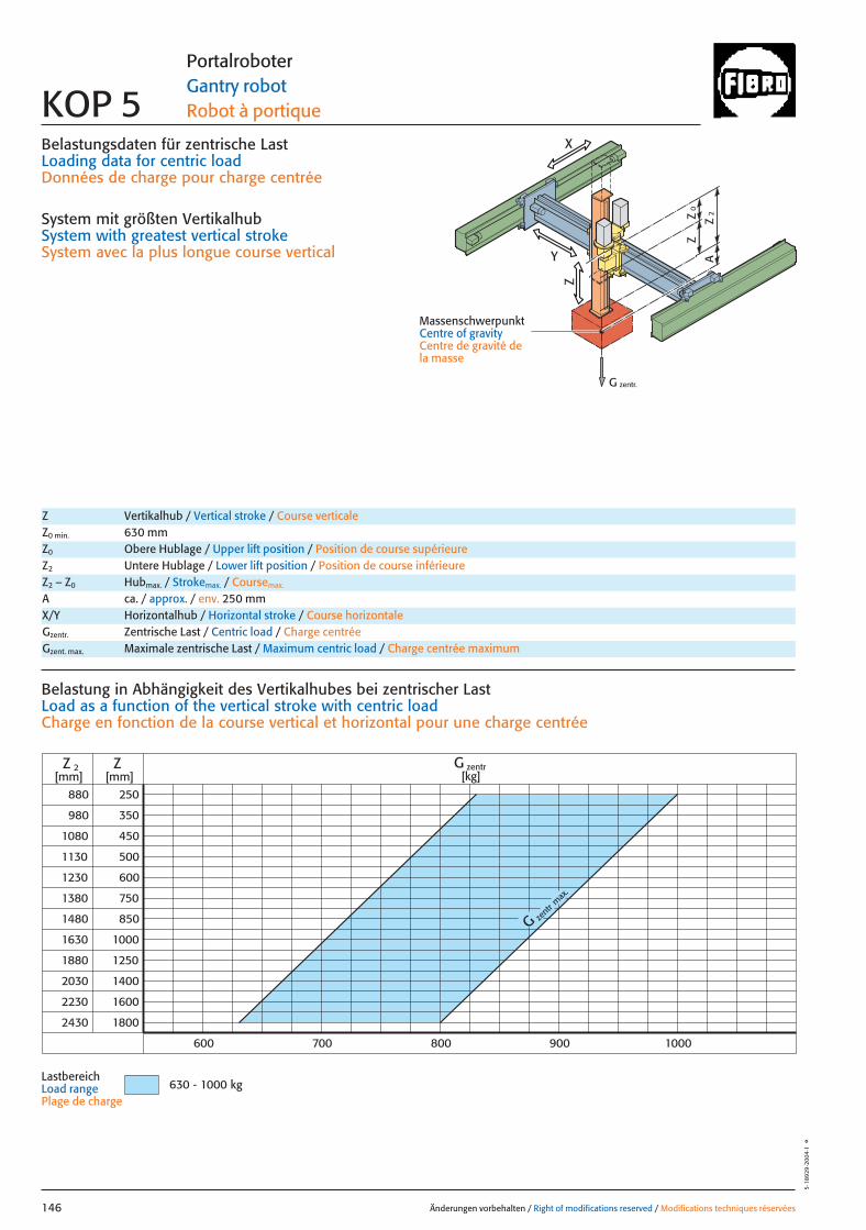
0Z
Z
2Z
A
G zentr.
Z
X
Y
Belastungsdaten für zentrische LastLoading data for centric loadDonnées de charge pour charge centrée
System mit größten VertikalhubSystem with greatest vertical strokeSystem avec la plus longue course vertical
MassenschwerpunktCentre of gravityCentre de gravité dela masse
880
980
1080
1130
1230
1380
1480
1630
1880
2030
2230
250
350
450
500
600
750
850
1000
1250
1400
1600
ZZ 2[mm] [mm]
800700600 900 1000
2430 1800
G zent
r max
.
G zentr[kg]
630 - 1000 kg
Änderungen vorbehalten / Right of modifications reserved / Modifications techniques réservées146
5·18
929
·200
4·1
°
Portalroboter Gantry robot Robot à portique KOP 5
Z Vertikalhub / Vertical stroke / Course verticaleZ0 min. 630 mmZ0 Obere Hublage / Upper lift position / Position de course supérieureZ2 Untere Hublage / Lower lift position / Position de course inférieureZ2 – Z0 Hubmax. / Strokemax. / Coursemax.
A ca. / approx. / env. 250 mm
Gzentr. Zentrische Last / Centric load / Charge centréeGzent. max. Maximale zentrische Last / Maximum centric load / Charge centrée maximum
X/Y Horizontalhub / Horizontal stroke / Course horizontale
Belastung in Abhängigkeit des Vertikalhubes bei zentrischer Last Load as a function of the vertical stroke with centric loadCharge en fonction de la course vertical et horizontal pour une charge centrée
LastbereichLoad range Plage de charge
146 27.08.2004 7:27 Uhr Seite 2

0Z
Z
2Z
A
Z
X
Y
x
Gy 2Gx
2y
1y *Gy 1
*
*
Änderungen vorbehalten / Right of modifications reserved / Modifications techniques réservées 147
5·18
930
·200
4·1
°Portalroboter Gantry robot Robot à portique KOP 5
Gexzent. max. Maximale exzentrische Last / Max. eccentric load / Charge excentrique max.Mkipp. Kippmoment / Tilting moment / Couple de renversement
Antriebsdaten / Drive data’s / Données de l’entraînement
GeschwindigkeitSpeed [m/sec] 2 2 3 1 0,5Vitesse
horizontal X horizontal Y vertikal / vertical
Wiederholgenauigkeit der PositionierungRepeat accuracy for positioning [mm] +/– 0,05 +/– 0,05 +/– 0,05 +/– 0,05 +/– 0,05Fidélité de reproduction du positionnement
BeschleunigungAcceleration [m/sec2] 3 4 4 2 2Accélération
Servomotor Siemens 1FT 6 Siemens 1FT 6 Siemens 1FT 6 Siemens 1FT 6 Siemens 1FT 6Servo motor Siemens 1FK 7 Siemens 1FK 7 Siemens 1FK 7 Siemens 1FK 7 Siemens 1FK 7ServomoteurPneumatischer GewichtsausgleichPneumatic weight compensation 1� �125Équilibrage pneumatique de poids
UntersetzungStep-down ratio 5:1 6:1 4:1 12,4:1 24,1:1Taux de réduction
= Gexzentr.x
Belastungsdaten für exzentrische Lastbezogen auf Mitte Befestigungslochbild Z-Achse für x; y
Loading data for eccentric loadreferred to the centre of the fixing hole pattern Z-axis for x; y
Données de charge pour une charge excentréerapporté au centre du gabarit des trous de fixation axe Z pour x; y
Verfahrtiefe des Massenschwerpunktes (Z2+A) bezogen auf Mitte Y-Laufschiene beim Verfahren in X oder Y RichtungTravel depth of the centre of mass (Z2+A) referred to the centre of the Y beam when travelling in X or Y directionDéplacement vertical du centre de gravité (Z2+A) par rapport au milieu du rail de roulement Y pour un déplacement dans la direction X ou Y
G [kg], x [m], y [m], Z2 [m], axzul.[m/sec2]
= Gexzentr.y
Gzentr. � 0,324
(y + 0,324)
Gzentr. � 0,24
(x + 0,24)
Gzent. max. = Gzentr.
aus Diagrammfrom diagramvaleur relevée dans le diagram
* MassenschwerpunktCentre of gravityCentre de gravité de la masse
= azul.
Mkipp.
G(Z2+A)
Mkipp.= 3600 NmG = Gzent., Gexzentr.
L 3
L 1L 2
Ständerbefestigung Column fixingFixation de poteau
L1 = 10000 mm Max. Profillänge, EinzelträgerMax. profile length, single beam Longueur max. de profilé, poutre individuel
L2 = 10000 mm Max. Profillänge, Träger mit TrennstelleMax. profile length, built-up beam Longueur max. de profilé, poutre composée
L3 = 6000 mm Max. freie TrägerlängeMax. free beam length Longueur libre max. de poutre
TrennstellePoint of separationPoint de sectionnement
Porta
lrobo
ter /
Gan
try ro
bot /
Rob
ot à
porti
que
Gzentr. = Gexzentr.
Verstärkte Tragrollen Y auf AnfrageReinforced support rollers Y on requestGalets porteur renforcé Y sur demande
147 27.08.2004 7:27 Uhr Seite 1
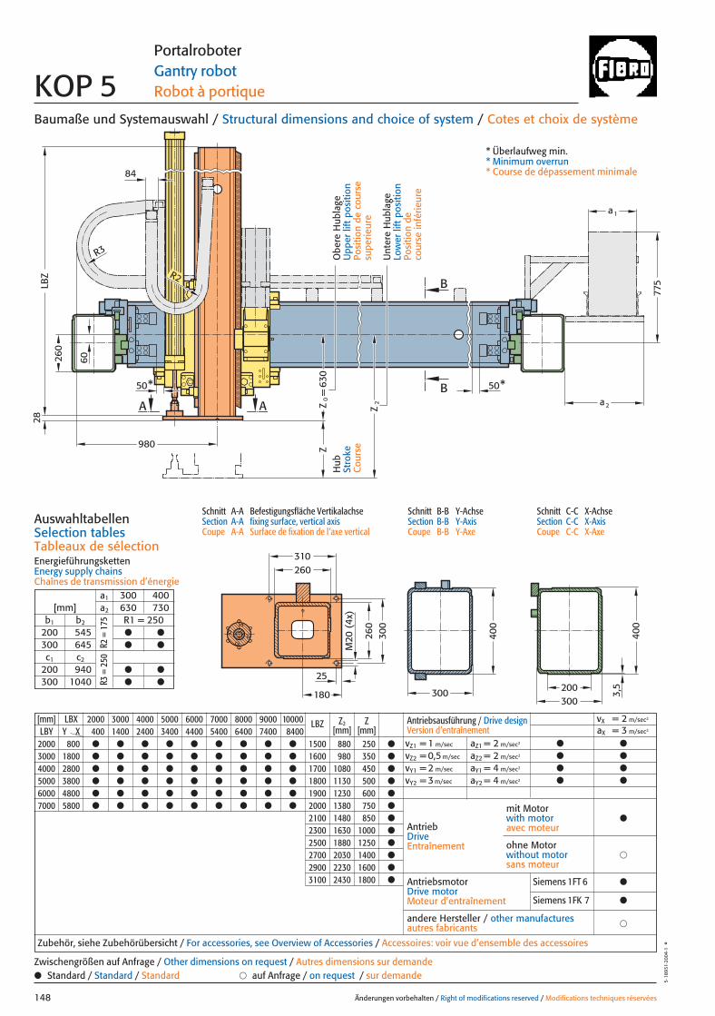
775
260
260
50
28
300
180
310
Z
A A
B
B
Z0=
Z2
25
M20
(4x
)
* 50*
LBZ
980
a2
a1
R3
R2
630
300
400
400
300200
3,5
260
60
84
[mm] LBX 2000 3000 4000 5000 6000 7000 8000 9000 10000 LBZ Z2 ZLBY Y X 400 1400 2400 3400 4400 5400 6400 7400 8400 [mm] [mm]
2000 800 ● ● ● ● ● ● ● ● ● 1500 880 250 ●
3000 1800 ● ● ● ● ● ● ● ● ● 1600 980 350 ●
4000 2800 ● ● ● ● ● ● ● ● ● 1700 1080 450 ●
5000 3800 ● ● ● ● ● ● ● ● ● 1800 1130 500 ●
6000 4800 ● ● ● ● ● ● ● ● ● 1900 1230 600 ●
7000 5800 ● ● ● ● ● ● ● ● ● 2000 1380 750 ●
2100 1480 850 ●
2300 1630 1000 ●
2500 1880 1250 ●
2700 2030 1400 ●
2900 2230 1600 ●
3100 2430 1800 ●
Baumaße und Systemauswahl / Structural dimensions and choice of system / Cotes et choix de système
Schnitt A-A Befestigungsfläche VertikalachseSection A-A fixing surface, vertical axisCoupe A-A Surface de fixation de l’axe vertical
Schnitt B-B Y-AchseSection B-B Y-AxisCoupe B-B Y-Axe
Schnitt C-C X-AchseSection C-C X-AxisCoupe C-C X-Axe
AuswahltabellenSelection tablesTableaux de sélectionEnergieführungskettenEnergy supply chainsChaînes de transmission d’énergie
Änderungen vorbehalten / Right of modifications reserved / Modifications techniques réservées148
5·18
931·
2004
·1°
Portalroboter Gantry robot Robot à portique KOP 5
Hub
Stro
keC
ours
e
Unt
ere
Hub
lage
Low
er li
ft p
ositi
onPo
sitio
n de
co
urse
infé
rieur
e
Obe
re H
ubla
geU
pper
lift
pos
ition
Posi
tion
de c
ours
e su
perie
ure
* Überlaufweg min.* Minimum overrun* Course de dépassement minimale
a1 300 400[mm] a2 630 730
b1 b2 R1 = 250200 545 ● ●
300 645 ● ●
c1 c2
200 940 ● ●
300 1040 ● ●
R2 =
175
R3 =
250
Antriebsausführung / Drive design Version d’entraînement
vX = 2 m/sec2
aX = 3 m/sec2
vZ1 = 1 m/sec aZ1 = 2 m/sec2 ● ●
vZ2 = 0,5 m/sec aZ2 = 2 m/sec2 ● ●
vY1 = 2 m/sec aY1 = 4 m/sec2 ● ●
vY2 = 3 m/sec aY2 = 4 m/sec2 ● ●
AntriebDriveEntraînement
AntriebsmotorDrive motorMoteur d’entraînement
�andere Hersteller / other manufacturesautres fabricants
Zubehör, siehe Zubehörübersicht / For accessories, see Overview of Accessories / Accessoires: voir vue d’ensemble des accessoires
mit Motorwith motoravec moteur
●
�ohne Motorwithout motorsans moteur
● Standard / Standard / Standard � auf Anfrage / on request / sur demandeZwischengrößen auf Anfrage / Other dimensions on request / Autres dimensions sur demande
Siemens 1FT 6 ●
Siemens 1FK 7 ●
148 27.08.2004 7:27 Uhr Seite 2
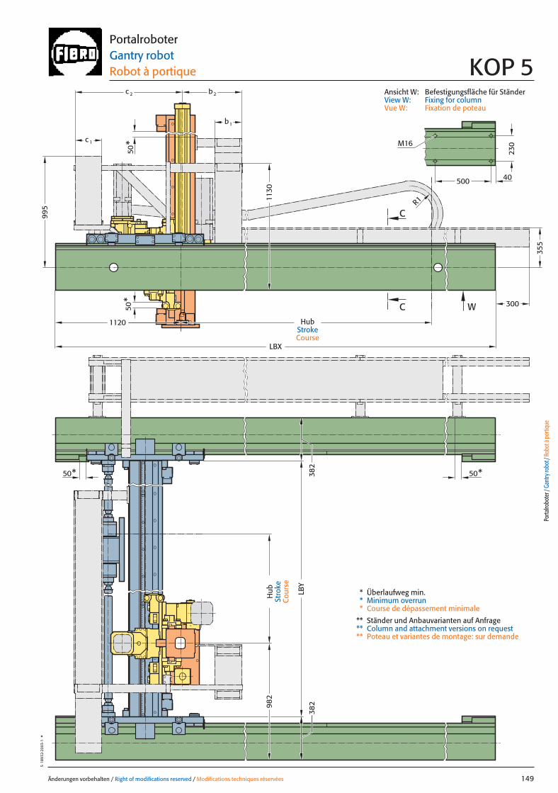
500
230
982
b1
LBY
LBX
50* 50*
50*
50*
C
C W
c 2 b2
c 1
995
355
300
R1
382
382
40
M16
1130
1120
Änderungen vorbehalten / Right of modifications reserved / Modifications techniques réservées 149
5·18
932·
2003
·1°
PortalroboterGantry robot Robot à portique KOP 5
* Überlaufweg min.* Minimum overrun* Course de dépassement minimale
** Ständer und Anbauvarianten auf Anfrage** Column and attachment versions on request** Poteau et variantes de montage: sur demande
Ansicht W: Befestigungsfläche für StänderView W: Fixing for columnVue W: Fixation de poteau
Porta
lrobo
ter /
Gan
try ro
bot /
Rob
ot à
porti
que
Hub
Stro
keC
ours
e
HubStrokeCourse
149 27.08.2004 7:27 Uhr Seite 1
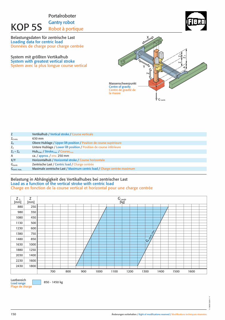
0Z
Z
2Z
A
G zentr.
Z
X
Y
Belastungsdaten für zentrische LastLoading data for centric loadDonnées de charge pour charge centrée
System mit größten VertikalhubSystem with greatest vertical strokeSystem avec la plus longue course vertical
MassenschwerpunktCentre of gravityCentre de gravité dela masse
880
980
1080
1130
1230
1380
1480
1630
1880
2030
2230
250
350
450
500
600
750
850
1000
1250
1400
1600
ZZ 2[mm] [mm]
900700
2430 1800
Gze
ntr
max
.
800 1000 1100 1200 1300 1400 1500 1600
G zentr[kg]
850 - 1450 kg
Änderungen vorbehalten / Right of modifications reserved / Modifications techniques réservées150
5·18
929
·200
4·1
°
Portalroboter Gantry robot Robot à portique KOP 5S
Z Vertikalhub / Vertical stroke / Course verticaleZ0 min. 630 mmZ0 Obere Hublage / Upper lift position / Position de course supérieureZ2 Untere Hublage / Lower lift position / Position de course inférieureZ2 – Z0 Hubmax. / Strokemax. / Coursemax.
A ca. / approx. / env. 250 mm
Gzentr. Zentrische Last / Centric load / Charge centréeGzent. max. Maximale zentrische Last / Maximum centric load / Charge centrée maximum
X/Y Horizontalhub / Horizontal stroke / Course horizontale
Belastung in Abhängigkeit des Vertikalhubes bei zentrischer Last Load as a function of the vertical stroke with centric loadCharge en fonction de la course vertical et horizontal pour une charge centrée
LastbereichLoad range Plage de charge
150 27.08.2004 7:27 Uhr Seite 2
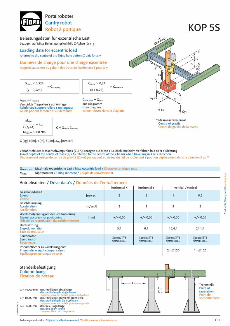
0Z
Z
2Z
A
Z
X
Y
x
Gy 2Gx
2y
1y *Gy 1
*
*
Änderungen vorbehalten / Right of modifications reserved / Modifications techniques réservées 151
5·18
930
·200
4·1
°Portalroboter Gantry robot Robot à portique KOP 5S
Gexzent. max. Maximale exzentrische Last / Max. eccentric load / Charge excentrique max.Mkipp. Kippmoment / Tilting moment / Couple de renversement
Antriebsdaten / Drive data’s / Données de l’entraînement
GeschwindigkeitSpeed [m/sec] 2 2 1 0,5Vitesse
horizontal X horizontal Y vertikal / vertical
Wiederholgenauigkeit der PositionierungRepeat accuracy for positioning [mm] +/– 0,05 +/– 0,05 +/– 0,05 +/– 0,05Fidélité de reproduction du positionnement
BeschleunigungAcceleration [m/sec2] 3 3 2 2Accélération
Servomotor Siemens 1FT 6 Siemens 1FT 6 Siemens 1FT 6 Siemens 1FT 6Servo motor Siemens 1FK 7 Siemens 1FK 7 Siemens 1FK 7 Siemens 1FK 7ServomoteurPneumatischer GewichtsausgleichPneumatic weight compensation 2� �125 1� �125Équilibrage pneumatique de poids
UntersetzungStep-down ratio 5:1 6:1 12,4:1 24,1:1Taux de réduction
= Gexzentr.x
Belastungsdaten für exzentrische Lastbezogen auf Mitte Befestigungslochbild Z-Achse für x; y
Loading data for eccentric loadreferred to the centre of the fixing hole pattern Z-axis for x; y
Données de charge pour une charge excentréerapporté au centre du gabarit des trous de fixation axe Z pour x; y
Verfahrtiefe des Massenschwerpunktes (Z2+A) bezogen auf Mitte Y-Laufschiene beim Verfahren in X oder Y RichtungTravel depth of the centre of mass (Z2+A) referred to the centre of the Y beam when travelling in X or Y directionDéplacement vertical du centre de gravité (Z2+A) par rapport au milieu du rail de roulement Y pour un déplacement dans la direction X ou Y
G [kg], x [m], y [m], Z2 [m], axzul.[m/sec2]
= Gexzentr.y
Gzentr. � 0,324
(y + 0,324)
Gzentr. � 0,24
(x + 0,24)
Gzent. max. = Gzentr.
aus Diagrammfrom diagramvaleur relevée dans le diagram
* MassenschwerpunktCentre of gravityCentre de gravité de la masse
= azul.
Mkipp.
G(Z2+A)
Mkipp.= 3600 NmG = Gzent., Gexzentr.
L 3
L 1L 2
Ständerbefestigung Column fixingFixation de poteau
L1 = 10000 mm Max. Profillänge, EinzelträgerMax. profile length, single beam Longueur max. de profilé, poutre individuel
L2 = 10000 mm Max. Profillänge, Träger mit TrennstelleMax. profile length, built-up beam Longueur max. de profilé, poutre composée
L3 = 6000 mm Max. freie TrägerlängeMax. free beam length Longueur libre max. de poutre
TrennstellePoint of separationPoint de sectionnement
Porta
lrobo
ter /
Gan
try ro
bot /
Rob
ot à
porti
que
Gzentr. = Gexzentr.
Verstärkte Tragrollen Y auf AnfrageReinforced support rollers Y on requestGalets porteur renforcé Y sur demande
151 27.08.2004 7:27 Uhr Seite 1
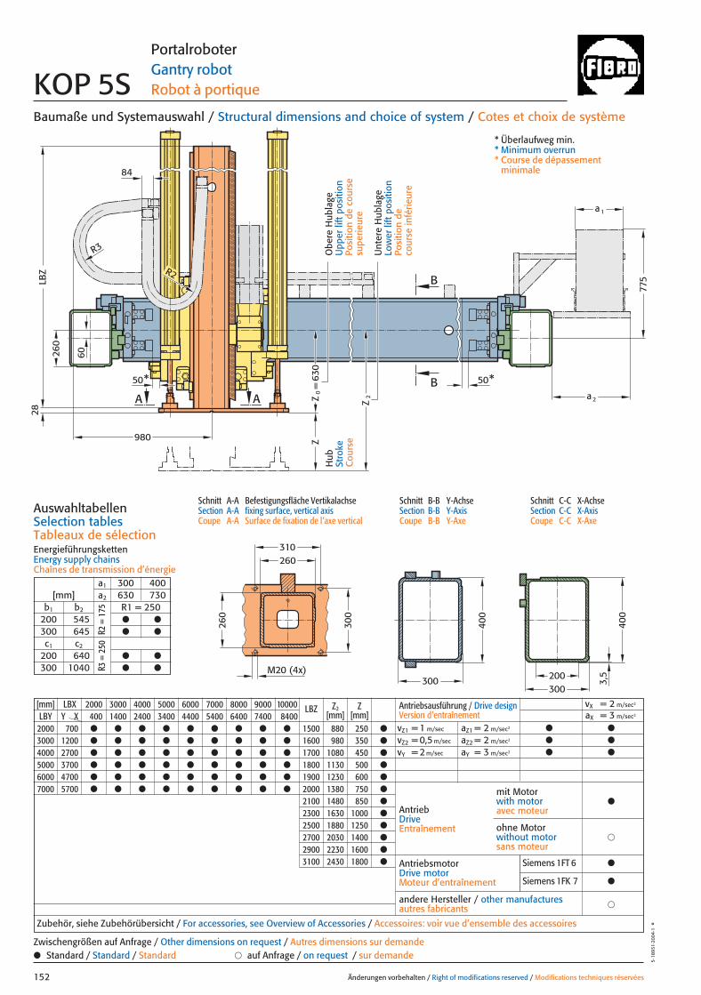
260
300
310
LBZ
28
B
BA A
ZZ
0=
Z2
M20 (4x)
50* 50*
260
R3
R2
980
630
775
a 2
a1
300
400
400
300200
3,5
84
260
60
[mm] LBX 2000 3000 4000 5000 6000 7000 8000 9000 10000 LBZ Z2 ZLBY Y X 400 1400 2400 3400 4400 5400 6400 7400 8400 [mm] [mm]
2000 700 ● ● ● ● ● ● ● ● ● 1500 880 250 ●
3000 1200 ● ● ● ● ● ● ● ● ● 1600 980 350 ●
4000 2700 ● ● ● ● ● ● ● ● ● 1700 1080 450 ●
5000 3700 ● ● ● ● ● ● ● ● ● 1800 1130 500 ●
6000 4700 ● ● ● ● ● ● ● ● ● 1900 1230 600 ●
7000 5700 ● ● ● ● ● ● ● ● ● 2000 1380 750 ●
2100 1480 850 ●
2300 1630 1000 ●
2500 1880 1250 ●
2700 2030 1400 ●
2900 2230 1600 ●
3100 2430 1800 ●
Baumaße und Systemauswahl / Structural dimensions and choice of system / Cotes et choix de système
Schnitt A-A Befestigungsfläche VertikalachseSection A-A fixing surface, vertical axisCoupe A-A Surface de fixation de l’axe vertical
Schnitt B-B Y-AchseSection B-B Y-AxisCoupe B-B Y-Axe
Schnitt C-C X-AchseSection C-C X-AxisCoupe C-C X-Axe
AuswahltabellenSelection tablesTableaux de sélectionEnergieführungskettenEnergy supply chainsChaînes de transmission d’énergie
Änderungen vorbehalten / Right of modifications reserved / Modifications techniques réservées152
5·18
931·
2004
·1°
Portalroboter Gantry robot Robot à portique KOP 5S
Hub
Stro
keC
ours
e
Unt
ere
Hub
lage
Low
er li
ft p
ositi
onPo
sitio
n de
co
urse
infé
rieur
e
Obe
re H
ubla
geU
pper
lift
pos
ition
Posi
tion
de c
ours
e su
perie
ure
* Überlaufweg min.* Minimum overrun* Course de dépassement
minimale
a1 300 400[mm] a2 630 730
b1 b2 R1 = 250200 545 ● ●
300 645 ● ●
c1 c2
200 640 ● ●
300 1040 ● ●
R2 =
175
R3 =
250
Antriebsausführung / Drive design Version d’entraînement
vX = 2 m/sec2
aX = 3 m/sec2
vZ1 = 1 m/sec aZ1 = 2 m/sec2 ● ●
vZ2 = 0,5 m/sec aZ2 = 2 m/sec2 ● ●
vY = 2 m/sec aY = 3 m/sec2 ● ●
AntriebDriveEntraînement
AntriebsmotorDrive motorMoteur d’entraînement
�andere Hersteller / other manufacturesautres fabricants
Zubehör, siehe Zubehörübersicht / For accessories, see Overview of Accessories / Accessoires: voir vue d’ensemble des accessoires
mit Motorwith motoravec moteur
●
�ohne Motorwithout motorsans moteur
● Standard / Standard / Standard � auf Anfrage / on request / sur demandeZwischengrößen auf Anfrage / Other dimensions on request / Autres dimensions sur demande
Siemens 1FT 6 ●
Siemens 1FK 7 ●
152 27.08.2004 7:27 Uhr Seite 2

982
LBX
50* 50*
50*
50*
WLB
Y
b1
c 2 b2
c 1
995
C
C
355
300
R1
382
382
500
230
40
M16
1130
1120
600
700
Änderungen vorbehalten / Right of modifications reserved / Modifications techniques réservées 153
5·18
932·
2003
·1°
PortalroboterGantry robot Robot à portique KOP 5S
* Überlaufweg min.* Minimum overrun* Course de dépassement minimale
** Ständer und Anbauvarianten auf Anfrage** Column and attachment versions on request** Poteau et variantes de montage: sur demande
Ansicht W: Befestigungsfläche für StänderView W: Fixing for columnVue W: Fixation de poteau
Porta
lrobo
ter /
Gan
try ro
bot /
Rob
ot à
porti
que
Hub
Stro
keC
ours
e
HubStrokeCourse
153 27.08.2004 7:28 Uhr Seite 1

Änderungen vorbehalten / Right of modifications reserved / Modifications techniques réservées154
5·18
927·
2003
·1°
154 27.08.2004 7:24 Uhr Seite 2
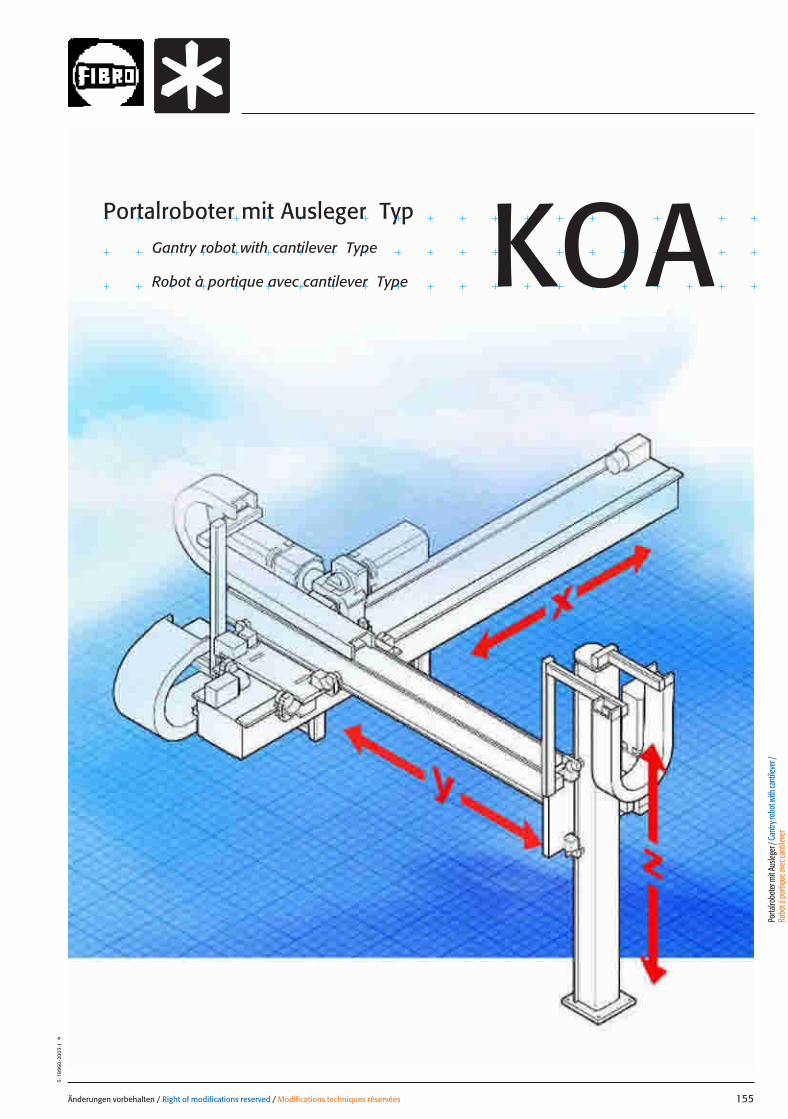
Änderungen vorbehalten / Right of modifications reserved / Modifications techniques réservées 155
5·18
960
·200
3·1
°
Portalroboter mit Ausleger TypGantry robot with cantilever Type
Robot à portique avec cantilever Type KOA
Porta
lrobo
ter m
it Aus
leger
/ Gan
try ro
bot w
ith ca
ntile
ver /
Ro
bot à
porti
que a
vec c
antile
ver
155 27.08.2004 10:51 Uhr Seite 1

X
Y
Z
0Z
Z
2Z
A
Y
Y
0
Belastungsdaten für zentrische LastLoading data for centric loadDonnées de charge pour charge centrée
System mit größten VertikalhubSystem with greatest vertical strokeSystem avec la plus longue course vertical
MassenschwerpunktCentre of gravityCentre de gravité de la masse
485
585
985
250
350
450
500
600
Z
5
Z 2[mm] [mm]
10
750
685
735
835
10 - 20 kg
G zentr[kg]
15 20 25 30 35 40 45
Ymax.200mmYmax.400mm
Gze
ntr
max
.
Änderungen vorbehalten / Right of modifications reserved / Modifications techniques réservées156
5·18
929
·200
4·1
°
Portalroboter mit AuslegerGantry robot with cantileverRobot à portique avec cantileverKOA 1
Z Vertikalhub / Vertical stroke / Course verticaleZ0 min. 235 mmZ0 Obere Hublage / Upper lift position / Position de course supérieureZ2 Untere Hublage / Lower lift position / Position de course inférieureZ2 – Z0 Hubmax. / Strokemax. / Coursemax.
A ca. / approx. / env. 100 mm
Gzentr. Zentrische Last / Centric load / Charge centréeGzent. max. Maximale zentrische Last / Maximum centric load / Charge centrée maximum
X / Y Horizontalhub / Horizontal stroke / Course horizontaleY0 355 mm
Belastung in Abhängigkeit des Vertikalhubes (Z) und der Horizontalhübe (X/Y) bei zentrischer Last Load as a function of the vertical (Z) and horizontal (X/Y) strokes with centric loadCharge en fonction de la courses vertical (Z) et horizontal (X/Y) pour une charge centrée
Gzentr.
LastbereichLoad range Plage de charge
156 27.08.2004 8:04 Uhr Seite 2
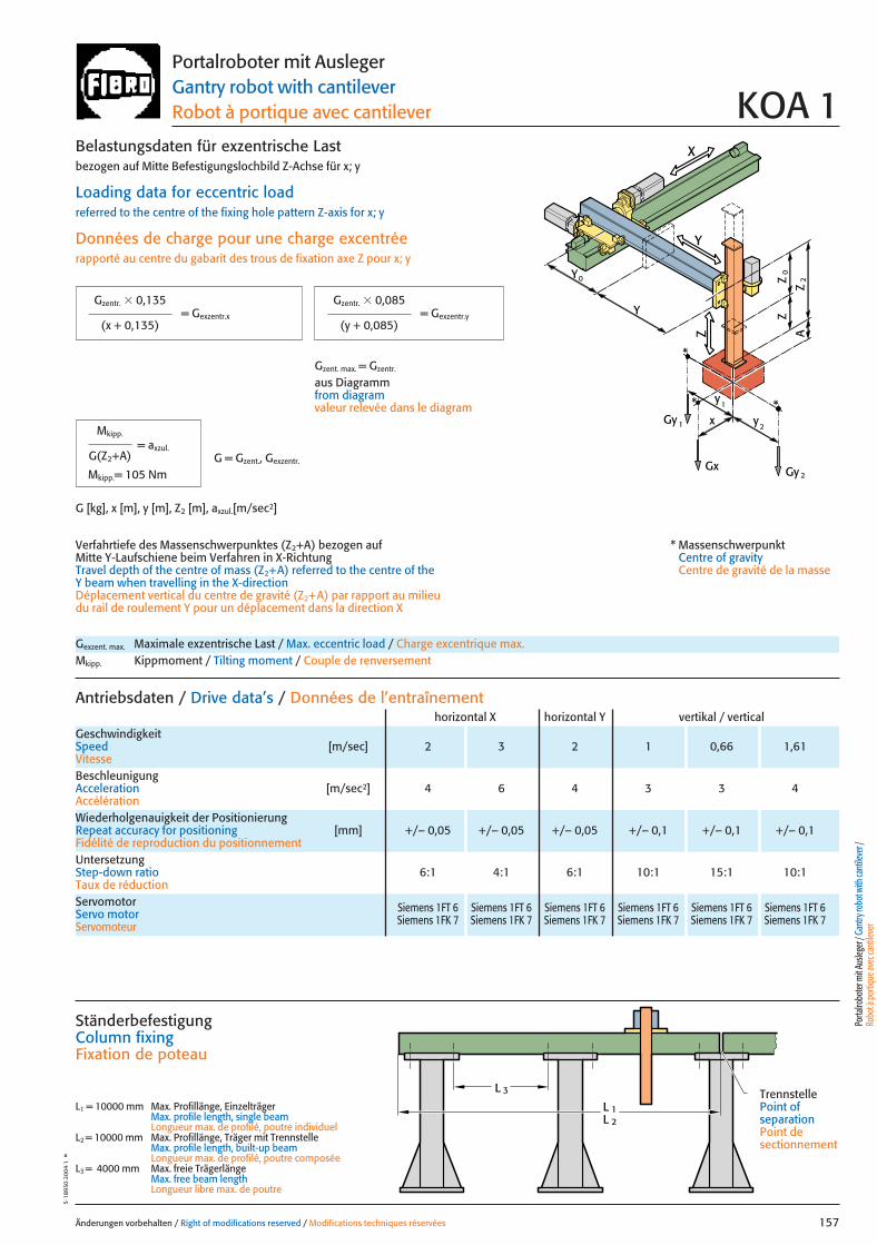
X
Y
Z
0Z
Z
2Z
A
x
Gy 2Gx
2y
1y *
Gy 1
Y
Y
0
*
*
Änderungen vorbehalten / Right of modifications reserved / Modifications techniques réservées 157
5·18
930
·200
4·1
°Portalroboter mit AuslegerGantry robot with cantileverRobot à portique avec cantilever KOA 1
Gexzent. max. Maximale exzentrische Last / Max. eccentric load / Charge excentrique max.Mkipp. Kippmoment / Tilting moment / Couple de renversement
Antriebsdaten / Drive data’s / Données de l’entraînement
GeschwindigkeitSpeed [m/sec] 2 3 2 1 0,66 1,61Vitesse
horizontal X horizontal Y vertikal / vertical
Wiederholgenauigkeit der PositionierungRepeat accuracy for positioning [mm] +/– 0,05 +/– 0,05 +/– 0,05 +/– 0,1 +/– 0,1 +/– 0,1Fidélité de reproduction du positionnement
BeschleunigungAcceleration [m/sec2] 4 6 4 3 3 4Accélération
Servomotor Siemens 1FT 6 Siemens 1FT 6 Siemens 1FT 6 Siemens 1FT 6 Siemens 1FT 6 Siemens 1FT 6Servo motor Siemens 1FK 7 Siemens 1FK 7 Siemens 1FK 7 Siemens 1FK 7 Siemens 1FK 7 Siemens 1FK 7Servomoteur
UntersetzungStep-down ratio 6:1 4:1 6:1 10:1 15:1 10:1Taux de réduction
= Gexzentr.y
Belastungsdaten für exzentrische Lastbezogen auf Mitte Befestigungslochbild Z-Achse für x; y
Loading data for eccentric loadreferred to the centre of the fixing hole pattern Z-axis for x; y
Données de charge pour une charge excentréerapporté au centre du gabarit des trous de fixation axe Z pour x; y
Verfahrtiefe des Massenschwerpunktes (Z2+A) bezogen auf Mitte Y-Laufschiene beim Verfahren in X-RichtungTravel depth of the centre of mass (Z2+A) referred to the centre of the Y beam when travelling in the X-directionDéplacement vertical du centre de gravité (Z2+A) par rapport au milieudu rail de roulement Y pour un déplacement dans la direction X
G [kg], x [m], y [m], Z2 [m], axzul.[m/sec2]
= Gexzentr.x
Gzentr. � 0,135
(x + 0,135)
Gzentr. � 0,085
(y + 0,085)
Gzent. max. = Gzentr.
aus Diagrammfrom diagramvaleur relevée dans le diagram
* MassenschwerpunktCentre of gravityCentre de gravité de la masse
= axzul.
Mkipp.
G(Z2+A)
Mkipp.= 105 NmG = Gzent., Gexzentr.
L 3
L 1L 2
Ständerbefestigung Column fixingFixation de poteau
L1 = 10000 mm Max. Profillänge, EinzelträgerMax. profile length, single beam Longueur max. de profilé, poutre individuel
L2 = 10000 mm Max. Profillänge, Träger mit TrennstelleMax. profile length, built-up beam Longueur max. de profilé, poutre composée
L3 = 4000 mm Max. freie TrägerlängeMax. free beam length Longueur libre max. de poutre
TrennstellePoint of separationPoint de sectionnement
Porta
lrobo
ter m
it Aus
leger
/ Gan
try ro
bot w
ith ca
ntile
ver /
Ro
bot à
porti
que a
vec c
antile
ver
157 27.08.2004 8:04 Uhr Seite 1
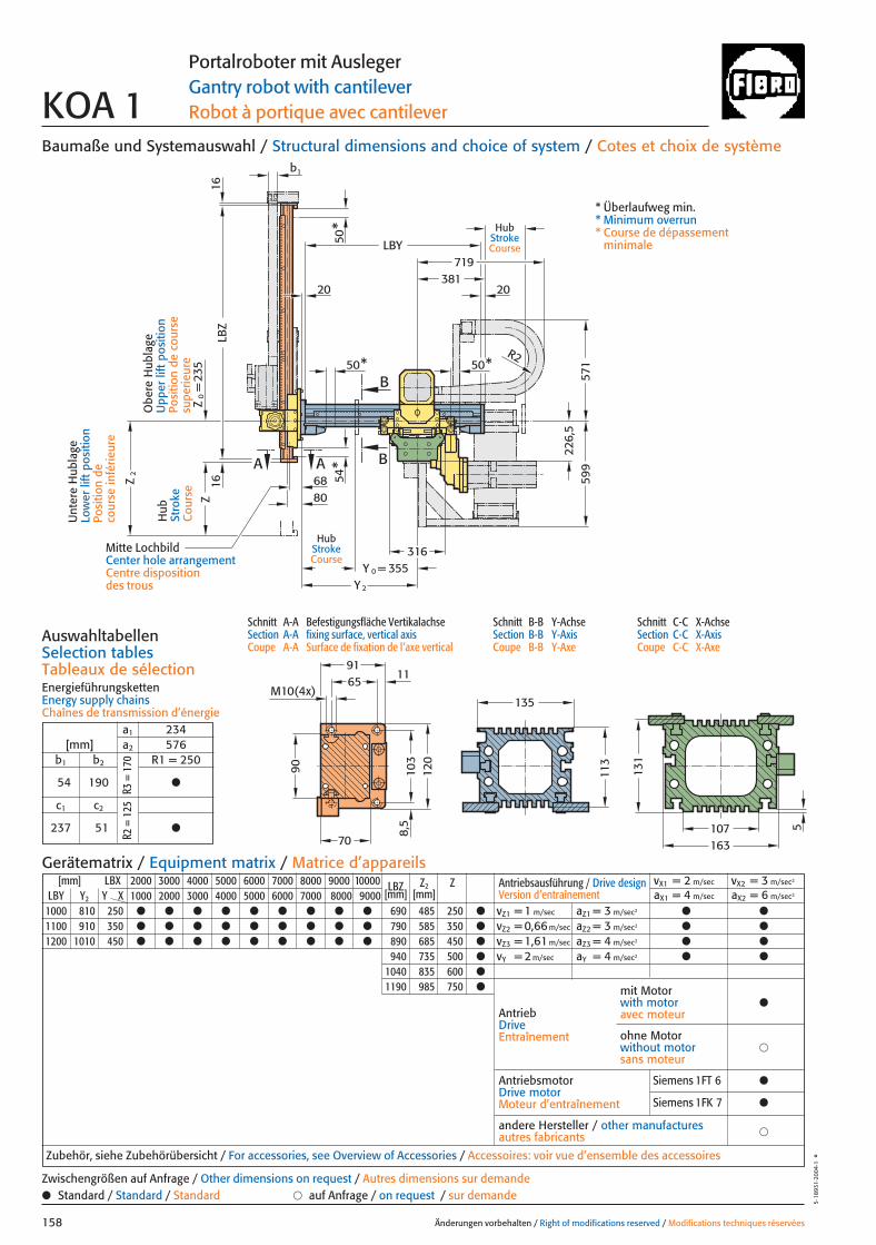
A
50
Z2
Y 2
31622
6,5
A
LBZ
1616
50* 50*
571
599
LBY
2020381
719
R2
b1
355Y 0 =
B
B
8068
ZZ
0=
235
54*
*
90 103
120
107
135
113
163
131
58,5
6591
11M10(4x)
70
Baumaße und Systemauswahl / Structural dimensions and choice of system / Cotes et choix de système
Schnitt A-A Befestigungsfläche VertikalachseSection A-A fixing surface, vertical axisCoupe A-A Surface de fixation de l’axe vertical
Schnitt B-B Y-AchseSection B-B Y-AxisCoupe B-B Y-Axe
Schnitt C-C X-AchseSection C-C X-AxisCoupe C-C X-Axe
AuswahltabellenSelection tablesTableaux de sélectionEnergieführungskettenEnergy supply chainsChaînes de transmission d’énergie
Änderungen vorbehalten / Right of modifications reserved / Modifications techniques réservées158
5·18
931·
2004
·1°
Portalroboter mit AuslegerGantry robot with cantileverRobot à portique avec cantileverKOA 1
Hub
Stro
keC
ours
e
Unt
ere
Hub
lage
Low
er li
ft p
ositi
onPo
sitio
n de
co
urse
infé
rieur
e
Obe
re H
ubla
geU
pper
lift
pos
ition
Posi
tion
de c
ours
e su
perie
ure
* Überlaufweg min.* Minimum overrun* Course de dépassement
minimale
[mm] LBX 2000 3000 4000 5000 6000 7000 8000 9000 10000 LBZ Z2 ZLBY Y2 Y X 1000 2000 3000 4000 5000 6000 7000 8000 9000 [mm] [mm]
1000 810 250 ● ● ● ● ● ● ● ● ● 690 485 250 ●
1100 910 350 ● ● ● ● ● ● ● ● ● 790 585 350 ●
1200 1010 450 ● ● ● ● ● ● ● ● ● 890 685 450 ●
940 735 500 ●
1040 835 600 ●
1190 985 750 ●
Antriebsausführung / Drive design Version d’entraînement
vX1 = 2 m/sec vX2 = 3 m/sec2
aX1 = 4 m/sec aX2 = 6 m/sec2
vZ1 = 1 m/sec aZ1 = 3 m/sec2 ● ●
vZ2 = 0,66 m/sec aZ2 = 3 m/sec2 ● ●
vZ3 = 1,61 m/sec aZ3 = 4 m/sec2 ● ●
vY = 2 m/sec aY = 4 m/sec2 ● ●
AntriebDriveEntraînement
AntriebsmotorDrive motorMoteur d’entraînement
�andere Hersteller / other manufacturesautres fabricants
Zubehör, siehe Zubehörübersicht / For accessories, see Overview of Accessories / Accessoires: voir vue d’ensemble des accessoires
mit Motorwith motoravec moteur
●
�ohne Motorwithout motorsans moteur
Gerätematrix / Equipment matrix / Matrice d’appareils
a1 234[mm] a2 576
b1 b2 R1 = 250
54 190 ●
c1 c2
237 51 ●
● Standard / Standard / Standard � auf Anfrage / on request / sur demandeZwischengrößen auf Anfrage / Other dimensions on request / Autres dimensions sur demande
R3 =
170
R2 =
125
Mitte LochbildCenter hole arrangementCentre disposition des trous
HubStrokeCourse
HubStrokeCourse
Siemens 1FT 6 ●
Siemens 1FK 7 ●
158 27.08.2004 8:04 Uhr Seite 2
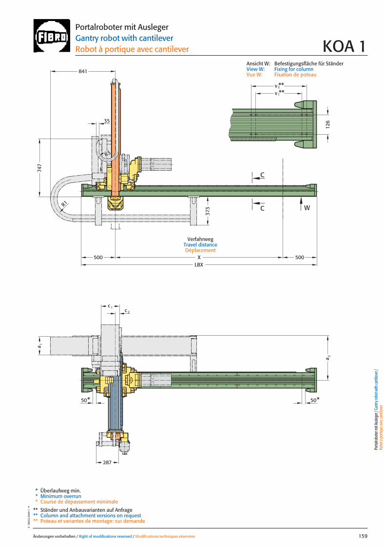
X
**
126
500LBX
W
C
C
50*
v**2v
1
50*
c 1c 2
a 2
a 1
287
500
841
35
373
747
R1
R3
Änderungen vorbehalten / Right of modifications reserved / Modifications techniques réservées 159
5·18
932·
2004
·1°
Portalroboter mit AuslegerGantry robot with cantileverRobot à portique avec cantilever KOA 1
* Überlaufweg min.* Minimum overrun* Course de dépassement minimale
** Ständer und Anbauvarianten auf Anfrage** Column and attachment versions on request** Poteau et variantes de montage: sur demande
VerfahrwegTravel distanceDéplacement
Porta
lrobo
ter m
it Aus
leger
/ Gan
try ro
bot w
ith ca
ntile
ver /
Ro
bot à
porti
que a
vec c
antile
ver
Ansicht W: Befestigungsfläche für StänderView W: Fixing for columnVue W: Fixation de poteau
159 27.08.2004 8:03 Uhr Seite 1
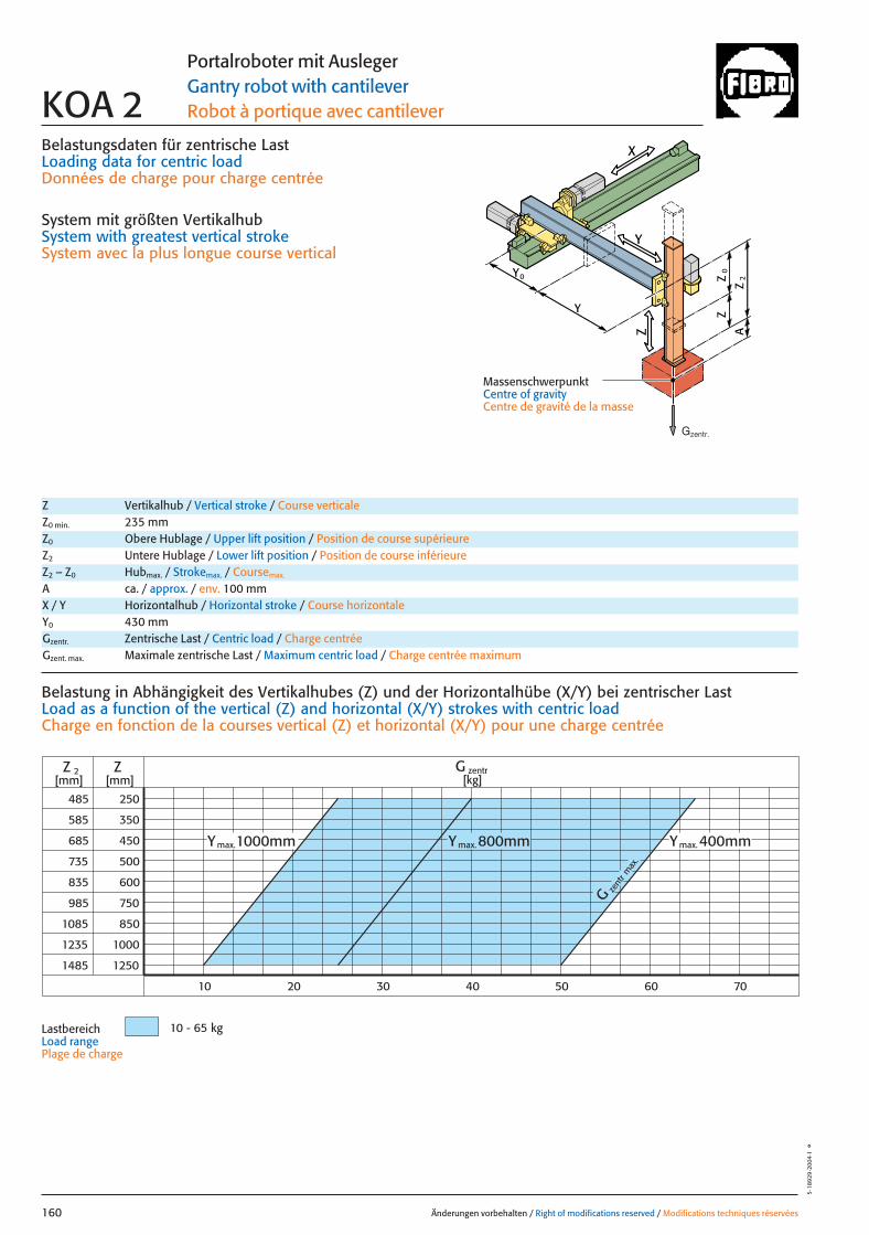
Belastungsdaten für zentrische LastLoading data for centric loadDonnées de charge pour charge centrée
System mit größten VertikalhubSystem with greatest vertical strokeSystem avec la plus longue course vertical
Ymax.800mm Ymax.400mmY
G zent
r max
.
485
585
985
1085
1235
1485
250
350
450
500
600
1000
1250
Z
10
Z 2[mm] [mm]
750
850
685
735
835
10 - 65 kg
G zentr[kg]
max.1000mm
20 30 40 50 60 70
Änderungen vorbehalten / Right of modifications reserved / Modifications techniques réservées160
5·18
929
·200
4·1
°
Portalroboter mit AuslegerGantry robot with cantileverRobot à portique avec cantileverKOA 2
Z Vertikalhub / Vertical stroke / Course verticaleZ0 min. 235 mmZ0 Obere Hublage / Upper lift position / Position de course supérieureZ2 Untere Hublage / Lower lift position / Position de course inférieureZ2 – Z0 Hubmax. / Strokemax. / Coursemax.
A ca. / approx. / env. 100 mm
Gzentr. Zentrische Last / Centric load / Charge centréeGzent. max. Maximale zentrische Last / Maximum centric load / Charge centrée maximum
X / Y Horizontalhub / Horizontal stroke / Course horizontaleY0 430 mm
Belastung in Abhängigkeit des Vertikalhubes (Z) und der Horizontalhübe (X/Y) bei zentrischer Last Load as a function of the vertical (Z) and horizontal (X/Y) strokes with centric loadCharge en fonction de la courses vertical (Z) et horizontal (X/Y) pour une charge centrée
LastbereichLoad range Plage de charge
X
Y
Z
0Z
Z
2Z
A
Y
Y
0
MassenschwerpunktCentre of gravityCentre de gravité de la masse
Gzentr.
160 27.08.2004 8:37 Uhr Seite 2

X
Y
Z
0Z
Z
2Z
A
x
Gy 2Gx
2y
1y *
Gy 1
Y
Y
0
*
*
Änderungen vorbehalten / Right of modifications reserved / Modifications techniques réservées 161
5·18
930
·200
4·1
°Portalroboter mit AuslegerGantry robot with cantileverRobot à portique avec cantilever KOA 2
Gexzent. max. Maximale exzentrische Last / Max. eccentric load / Charge excentrique max.Mkipp. Kippmoment / Tilting moment / Couple de renversement
Antriebsdaten / Drive data’s / Données de l’entraînement
GeschwindigkeitSpeed [m/sec] 2 3 2 1 0,66 1,61Vitesse
horizontal X horizontal Y vertikal / vertical
Wiederholgenauigkeit der PositionierungRepeat accuracy for positioning [mm] +/– 0,05 +/– 0,05 +/– 0,05 +/– 0,05 +/– 0,05 +/– 0,05Fidélité de reproduction du positionnement
BeschleunigungAcceleration [m/sec2] 4 6 4 3 3 4Accélération
Servomotor Siemens 1FT 6 Siemens 1FT 6 Siemens 1FT 6 Siemens 1FT 6 Siemens 1FT 6 Siemens 1FT 6Servo motor Siemens 1FK 7 Siemens 1FK 7 Siemens 1FK 7 Siemens 1FK 7 Siemens 1FK 7 Siemens 1FK 7Servomoteur
UntersetzungStep-down ratio 6:1 4:1 6:1 15:1 25:1 10:1Taux de réduction
= Gexzentr.y
Belastungsdaten für exzentrische Lastbezogen auf Mitte Befestigungslochbild Z-Achse für x; y
Loading data for eccentric loadreferred to the centre of the fixing hole pattern Z-axis for x; y
Données de charge pour une charge excentréerapporté au centre du gabarit des trous de fixation axe Z pour x; y
Verfahrtiefe des Massenschwerpunktes (Z2+A) bezogen auf Mitte Y-Laufschiene beim Verfahren in X-RichtungTravel depth of the centre of mass (Z2+A) referred to the centre of the Y beam when travelling in the X-directionDéplacement vertical du centre de gravité (Z2+A) par rapport au milieudu rail de roulement Y pour un déplacement dans la direction X
G [kg], x [m], y [m], Z2 [m], axzul.[m/sec2]
= Gexzentr.x
Gzentr. � 0,135
(x + 0,135)
Gzentr. � 0,085
(y + 0,085)
Gzent. max. = Gzentr.
aus Diagrammfrom diagramvaleur relevée dans le diagram
* MassenschwerpunktCentre of gravityCentre de gravité de la masse
= axzul.
Mkipp.
G(Z2+A)
Mkipp.= 210 NmG = Gzent., Gexzentr.
L 3
L 1L 2
Ständerbefestigung Column fixingFixation de poteau
L1 = 10000 mm Max. Profillänge, EinzelträgerMax. profile length, single beam Longueur max. de profilé, poutre individuel
L2 = 10000 mm Max. Profillänge, Träger mit TrennstelleMax. profile length, built-up beam Longueur max. de profilé, poutre composée
L3 = 6000 mm Max. freie TrägerlängeMax. free beam length Longueur libre max. de poutre
TrennstellePoint of separationPoint de sectionnement
Porta
lrobo
ter m
it Aus
leger
/ Gan
try ro
bot w
ith ca
ntile
ver /
Ro
bot à
porti
que a
vec c
antile
ver
161 27.08.2004 8:37 Uhr Seite 1
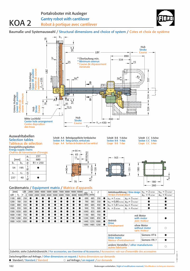
b1
72,5
Y 2
460
50*
50*
890534
180260
4
180
M10
(4x)
6591
8,5
120
103
11 163
131
557
314
324
R2
B
BA A
LBZ
16
54*
16
1525
LBY
50*
430Y 0 =
Z0
=23
5Z
Z2
91
b2
70
90
Baumaße und Systemauswahl / Structural dimensions and choice of system / Cotes et choix de système
Schnitt A-A Befestigungsfläche VertikalachseSection A-A fixing surface, vertical axisCoupe A-A Surface de fixation de l’axe vertical
Schnitt B-B Y-AchseSection B-B Y-AxisCoupe B-B Y-Axe
Schnitt C-C X-AchseSection C-C X-AxisCoupe C-C X-Axe
AuswahltabellenSelection tablesTableaux de sélectionEnergieführungskettenEnergy supply chainsChaînes de transmission d’énergie
Änderungen vorbehalten / Right of modifications reserved / Modifications techniques réservées162
5·18
931·
2004
·1°
Portalroboter mit AuslegerGantry robot with cantileverRobot à portique avec cantileverKOA 2
[mm] LBX 2000 3000 4000 5000 6000 7000 8000 9000 10000 LBZ Z2 ZLBY Y2 Y X 1000 2000 3000 4000 5000 6000 7000 8000 9000 [mm] [mm]
1100 680 250 ● ● ● ● ● ● ● ● ● 690 485 250 ●
1200 780 350 ● ● ● ● ● ● ● ● ● 790 585 350 ●
1300 880 450 ● ● ● ● ● ● ● ● ● 890 685 450 ●
1400 930 500 ● ● ● ● ● ● ● ● ● 940 735 500 ●
1500 1030 600 ● ● ● ● ● ● ● ● ● 1040 835 600 ●
1600 1180 750 ● ● ● ● ● ● ● ● ● 1190 985 750 ●
1700 1280 850 ● ● ● ● ● ● ● ● ● 1240 1085 850 ●
1900 1430 1000 ● ● ● ● ● ● ● ● ● 1440 1235 1000 ●
1690 1485 1250 ●
Antriebsausführung / Drive design Version d’entraînement
vX1 = 2 m/sec vX2 = 3 m/sec2
aX1 = 4 m/sec aX2 = 6 m/sec2
vZ1 = 1 m/sec aZ1 = 3 m/sec2 ● ●
vZ2 = 0,66 m/sec aZ2 = 3 m/sec2 ● ●
vZ3 = 1,61 m/sec aZ3 = 4 m/sec2 ● ●
vY = 2 m/sec aY = 4 m/sec2 ● ●
AntriebDriveEntraînement
AntriebsmotorDrive motorMoteur d’entraînement
�andere Hersteller / other manufacturesautres fabricants
Zubehör, siehe Zubehörübersicht / For accessories, see Overview of Accessories / Accessoires: voir vue d’ensemble des accessoires
mit Motorwith motoravec moteur
●
�ohne Motorwithout motorsans moteur
Gerätematrix / Equipment matrix / Matrice d’appareils
● Standard / Standard / Standard � auf Anfrage / on request / sur demandeZwischengrößen auf Anfrage / Other dimensions on request / Autres dimensions sur demande
HubStrokeCourse
Hub
Stro
keC
ours
e
HubStrokeCourse
Obe
re H
ubla
geU
pper
lift
pos
ition
Posi
tion
de c
ours
e su
perie
ure
* Überlaufweg min.* Minimum overrun* Course de dépassement
minimale
Mitte LochbildCenter hole arrangementCentre disposition des trous
Unt
ere
Hub
lage
Low
er li
ft p
ositi
onPo
sitio
n de
co
urse
infé
rieur
e
a1 237[mm] a2 680
b1 b2 R1 = 250
54 195 ●
c1 c2
237 40 ●
R3 =
170
R2 =
125
Siemens 1FT 6 ●
Siemens 1FK 7 ●
162 27.08.2004 8:37 Uhr Seite 2
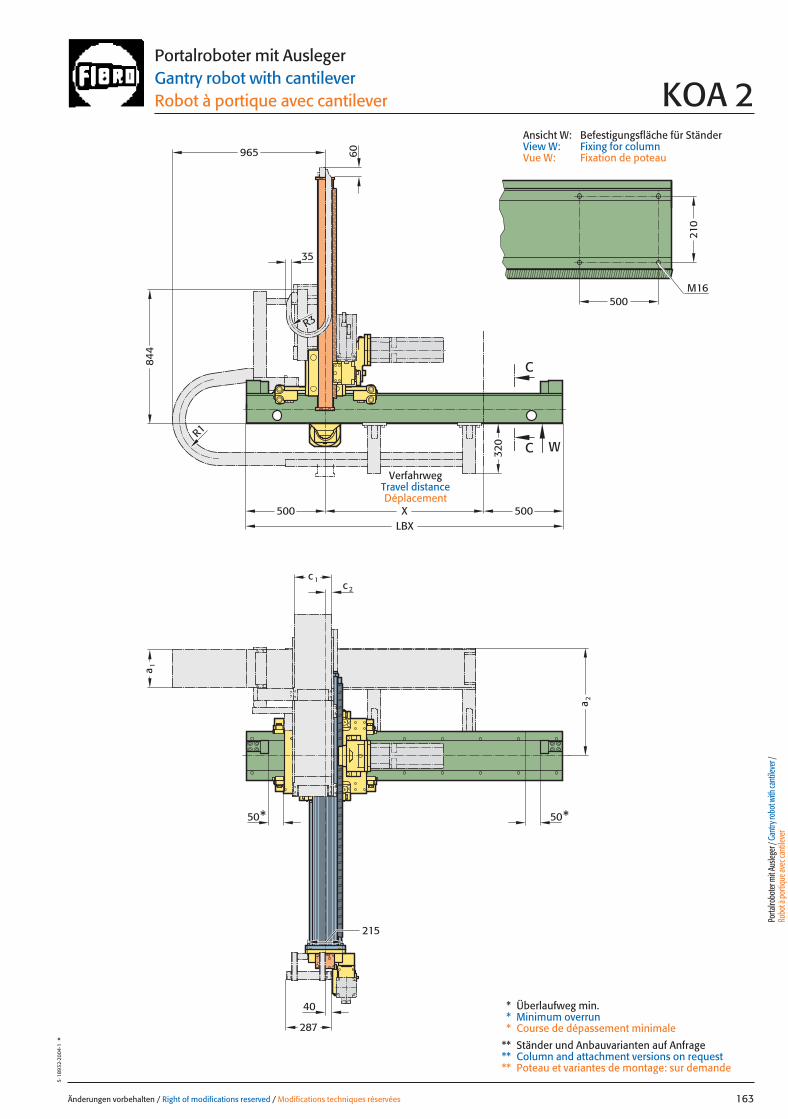
R1
X500
40
W
R3
500
210
M16
c 1c 2
287
a 2
a 1
215
C
C
LBX500
320
96584
4
35
60
50* 50*
Änderungen vorbehalten / Right of modifications reserved / Modifications techniques réservées 163
5·18
932·
2004
·1°
Portalroboter mit AuslegerGantry robot with cantileverRobot à portique avec cantilever KOA 2
* Überlaufweg min.* Minimum overrun* Course de dépassement minimale
** Ständer und Anbauvarianten auf Anfrage** Column and attachment versions on request** Poteau et variantes de montage: sur demande
Ansicht W: Befestigungsfläche für StänderView W: Fixing for columnVue W: Fixation de poteau
VerfahrwegTravel distanceDéplacement
Porta
lrobo
ter m
it Aus
leger
/ Gan
try ro
bot w
ith ca
ntile
ver /
Ro
bot à
porti
que a
vec c
antile
ver
163 27.08.2004 8:38 Uhr Seite 1
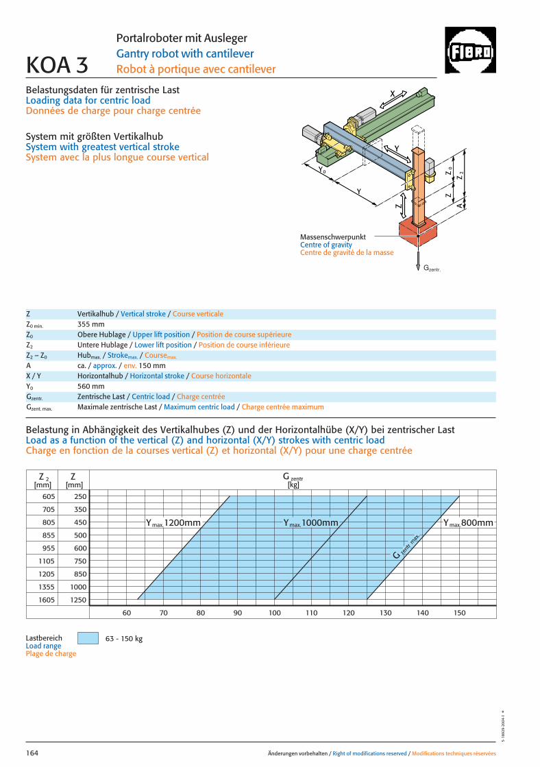
Belastungsdaten für zentrische LastLoading data for centric loadDonnées de charge pour charge centrée
System mit größten VertikalhubSystem with greatest vertical strokeSystem avec la plus longue course vertical
G zent
r max
.
605
705
1105
1205
1355
1605
250
350
450
500
600
1000
1250
ZZ 2[mm] [mm]
70 80 90 150
750
850
805
855
955
60 140130120110100
G zentr[kg]
63 - 150 kg
Ymax.800mmYmax.1200mm Ymax.1000mm
Änderungen vorbehalten / Right of modifications reserved / Modifications techniques réservées164
5·18
929
·200
4·1
°
Portalroboter mit AuslegerGantry robot with cantileverRobot à portique avec cantileverKOA 3
Z Vertikalhub / Vertical stroke / Course verticaleZ0 min. 355 mmZ0 Obere Hublage / Upper lift position / Position de course supérieureZ2 Untere Hublage / Lower lift position / Position de course inférieureZ2 – Z0 Hubmax. / Strokemax. / Coursemax.
A ca. / approx. / env. 150 mm
Gzentr. Zentrische Last / Centric load / Charge centréeGzent. max. Maximale zentrische Last / Maximum centric load / Charge centrée maximum
X / Y Horizontalhub / Horizontal stroke / Course horizontaleY0 560 mm
Belastung in Abhängigkeit des Vertikalhubes (Z) und der Horizontalhübe (X/Y) bei zentrischer Last Load as a function of the vertical (Z) and horizontal (X/Y) strokes with centric loadCharge en fonction de la courses vertical (Z) et horizontal (X/Y) pour une charge centrée
LastbereichLoad range Plage de charge
X
Y
Z
0Z
Z
2Z
A
Y
Y
0
MassenschwerpunktCentre of gravityCentre de gravité de la masse
Gzentr.
164 27.08.2004 8:04 Uhr Seite 2

X
Y
Z
0Z
Z
2Z
A
x
Gy 2Gx
2y
1y *
Gy 1
Y
Y
0
*
*
Änderungen vorbehalten / Right of modifications reserved / Modifications techniques réservées 165
5·18
930
·200
4·1
°Portalroboter mit AuslegerGantry robot with cantileverRobot à portique avec cantilever KOA 3
Gexzent. max. Maximale exzentrische Last / Max. eccentric load / Charge excentrique max.Mkipp. Kippmoment / Tilting moment / Couple de renversement
Antriebsdaten / Drive data’s / Données de l’entraînement
GeschwindigkeitSpeed [m/sec] 2 3 2 1 0,62 1,61Vitesse
horizontal X horizontal Y vertikal / vertical
Wiederholgenauigkeit der PositionierungRepeat accuracy for positioning [mm] +/– 0,05 +/– 0,05 +/– 0,05 +/– 0,05 +/– 0,05 +/– 0,05Fidélité de reproduction du positionnement
BeschleunigungAcceleration [m/sec2] 4 6 4 3 3 4Accélération
Servomotor Siemens 1FT 6 Siemens 1FT 6 Siemens 1FT 6 Siemens 1FT 6 Siemens 1FT 6 Siemens 1FT 6Servo motor Siemens 1FK 7 Siemens 1FK 7 Siemens 1FK 7 Siemens 1FK 7 Siemens 1FK 7 Siemens 1FK 7Servomoteur
UntersetzungStep-down ratio 6:1 4:1 6:1 10,2:1 16,1:1 10,2:1Taux de réduction
= Gexzentr.y
Belastungsdaten für exzentrische Lastbezogen auf Mitte Befestigungslochbild Z-Achse für x; y
Loading data for eccentric loadreferred to the centre of the fixing hole pattern Z-axis for x; y
Données de charge pour une charge excentréerapporté au centre du gabarit des trous de fixation axe Z pour x; y
Verfahrtiefe des Massenschwerpunktes (Z2+A) bezogen auf Mitte Y-Laufschiene beim Verfahren in X-RichtungTravel depth of the centre of mass (Z2+A) referred to the centre of the Y beam when travelling in the X-directionDéplacement vertical du centre de gravité (Z2+A) par rapport au milieudu rail de roulement Y pour un déplacement dans la direction X
G [kg], x [m], y [m], Z2 [m], axzul.[m/sec2]
= Gexzentr.x
Gzentr. � 0,175
(x + 0,175)
Gzentr. � 0,131
(y + 0,131)
Gzent. max. = Gzentr.
aus Diagrammfrom diagramvaleur relevée dans le diagram
* MassenschwerpunktCentre of gravityCentre de gravité de la masse
= axzul.
Mkipp.
G(Z2+A)
Mkipp.= 350 NmG = Gzent., Gexzentr.
L 3
L 1L 2
Ständerbefestigung Column fixingFixation de poteau
L1 = 10000 mm Max. Profillänge, EinzelträgerMax. profile length, single beam Longueur max. de profilé, poutre individuel
L2 = 10000 mm Max. Profillänge, Träger mit TrennstelleMax. profile length, built-up beam Longueur max. de profilé, poutre composée
L3 = 6000 mm Max. freie TrägerlängeMax. free beam length Longueur libre max. de poutre
TrennstellePoint of separationPoint de sectionnement
Porta
lrobo
ter m
it Aus
leger
/ Gan
try ro
bot w
ith ca
ntile
ver /
Ro
bot à
porti
que a
vec c
antile
ver
165 27.08.2004 8:04 Uhr Seite 1
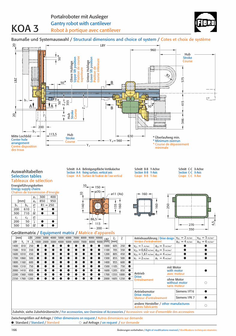
135
86,5113
LBY
630
Z
Z2
=b 1
200b2
*50
*
20LB
Z20
A A
50
50*
113,5
Z0
B
B
160
140
10
ø7015010
ø11 (4x)
200
560Y 0 =Y 2
50*
346
960
R2
160
160
250
270350
415
575
355
4,5
Baumaße und Systemauswahl / Structural dimensions and choice of system / Cotes et choix de système
Schnitt A-A Befestigungsfläche VertikalachseSection A-A fixing surface, vertical axisCoupe A-A Surface de fixation de l’axe vertical
Schnitt B-B Y-AchseSection B-B Y-AxisCoupe B-B Y-Axe
Schnitt C-C X-AchseSection C-C X-AxisCoupe C-C X-Axe
AuswahltabellenSelection tablesTableaux de sélectionEnergieführungskettenEnergy supply chainsChaînes de transmission d’énergie
Änderungen vorbehalten / Right of modifications reserved / Modifications techniques réservées166
Portalroboter mit AuslegerGantry robot with cantileverRobot à portique avec cantileverKOA 3
Hub
Stro
keC
ours
e
HubStrokeCourse
HubStrokeCourse
* Überlaufweg min.* Minimum overrun* Course de dépassement
minimale
[mm] LBX 2000 3000 4000 5000 6000 7000 8000 9000 10000 LBZ Z2 ZLBY Y2 Y X 1000 2000 3000 4000 5000 6000 7000 8000 9000 [mm] [mm]
1400 810 250 ● ● ● ● ● ● ● ● ● 1000 605 250 ●
1500 910 350 ● ● ● ● ● ● ● ● ● 1100 705 350 ●
1600 1010 450 ● ● ● ● ● ● ● ● ● 1200 805 450 ●
1700 1060 500 ● ● ● ● ● ● ● ● ● 1300 855 500 ●
1800 1160 600 ● ● ● ● ● ● ● ● ● 1400 955 600 ●
1900 1310 750 ● ● ● ● ● ● ● ● ● 1500 1105 750 ●
2000 1410 850 ● ● ● ● ● ● ● ● ● 1600 1205 850 ●
2200 1560 1000 ● ● ● ● ● ● ● ● ● 1700 1355 1000 ●
2350 1760 1200 ● ● ● ● ● ● ● ● ● 2000 1605 1250 ●
Antriebsausführung / Drive design Version d’entraînement
vX1 = 2 m/sec vX2 = 3 m/sec2
aX1 = 4 m/sec aX2 = 6 m/sec2
vZ1 = 1 m/sec aZ1 = 3 m/sec2 ● ●
vZ2 = 0,62 m/sec aZ2 = 3 m/sec2 ● ●
vZ3 = 1,61 m/sec aZ3 = 4 m/sec2 ● ●
vY = 2 m/sec aY = 4 m/sec2 ● ●
AntriebDriveEntraînement
AntriebsmotorDrive motorMoteur d’entraînement
�andere Hersteller / other manufacturesautres fabricants
Zubehör, siehe Zubehörübersicht / For accessories, see Overview of Accessories / Accessoires: voir vue d’ensemble des accessoires
mit Motorwith motoravec moteur
●
�ohne Motorwithout motorsans moteur
Gerätematrix / Equipment matrix / Matrice d’appareils
a1 300 400[mm] a2 850 950
b1 b2 R1 = 250200 610 ● ●
300 710 ● ●
c1 c2
200 50 ● ●
300 50 ● ●
● Standard / Standard / Standard � auf Anfrage / on request / sur demandeZwischengrößen auf Anfrage / Other dimensions on request / Autres dimensions sur demande
R3 =
175
R2 =
175
Mitte LochbildCenter hole arrangementCentre disposition des trous
Unt
ere
Hub
lage
Low
er li
ft p
ositi
onPo
sitio
n de
co
urse
infé
rieur
e
Obe
re H
ubla
geU
pper
lift
pos
ition
Posi
tion
de c
ours
e su
perie
ure
Siemens 1FT 6 ●
Siemens 1FK 7 ●
166 27.08.2004 8:04 Uhr Seite 2
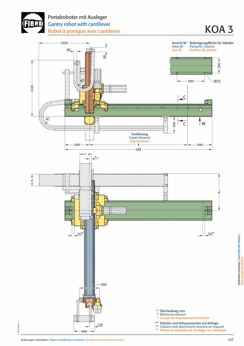
Änderungen vorbehalten / Right of modifications reserved / Modifications techniques réservées 167
5·18
932·
2004
·1°
Portalroboter mit AuslegerGantry robot with cantileverRobot à portique avec cantilever KOA 3
Ansicht W: Befestigungsfläche für StänderView W: Fixing for columnVue W: Fixation de poteau
VerfahrwegTravel distanceDéplacement
Porta
lrobo
ter m
it Aus
leger
/ Gan
try ro
bot w
ith ca
ntile
ver /
Ro
bot à
porti
que a
vec c
antile
ver
XLBX
W
50* 50*
400
1030
1225
84
500 500
90
500
290
R1
R3 M16
C
C
460
130
a 1
a 2
c 1c 2
350
* Überlaufweg min.* Minimum overrun* Course de dépassement minimale
** Ständer und Anbauvarianten auf Anfrage** Column and attachment versions on request** Poteau et variantes de montage: sur demande
167 27.08.2004 8:05 Uhr Seite 1

Belastungsdaten für zentrische LastLoading data for centric loadDonnées de charge pour charge centrée
System mit größten VertikalhubSystem with greatest vertical strokeSystem avec la plus longue course vertical
1250mmY 1400mm
zent
r
G
max
.
680
780
880
930
1030
1180
1280
1430
1680
1830
2030
250
350
450
500
600
750
850
1000
1250
1400
1600
Z
130 140 150 160 170 180 190 200 210 220 230 240 250 260 270 280 290 300 310
Z 2 G zentr[kg][mm] [mm]
130 - 300 kg
Ymax.1600mm Ymax.1000mmYmax.max.
Änderungen vorbehalten / Right of modifications reserved / Modifications techniques réservées168
5·18
929
·200
4·1
°
Portalroboter mit AuslegerGantry robot with cantileverRobot à portique avec cantileverKOA 4
Z Vertikalhub / Vertical stroke / Course verticaleZ0 min. 430 mmZ0 Obere Hublage / Upper lift position / Position de course supérieureZ2 Untere Hublage / Lower lift position / Position de course inférieureZ2 – Z0 Hubmax. / Strokemax. / Coursemax.
A ca. / approx. / env. 150 mm
Gzentr. Zentrische Last / Centric load / Charge centréeGzent. max. Maximale zentrische Last / Maximum centric load / Charge centrée maximum
X / Y Horizontalhub / Horizontal stroke / Course horizontaleY0 630 mm
Belastung in Abhängigkeit des Vertikalhubes (Z) und der Horizontalhübe (X/Y) bei zentrischer Last Load as a function of the vertical (Z) and horizontal (X/Y) strokes with centric loadCharge en fonction de la courses vertical (Z) et horizontal (X/Y) pour une charge centrée
LastbereichLoad range Plage de charge
X
Y
Z
0Z
Z
2Z
A
Y
Y
0
MassenschwerpunktCentre of gravityCentre de gravité de la masse
Gzentr.
168 27.08.2004 8:38 Uhr Seite 2
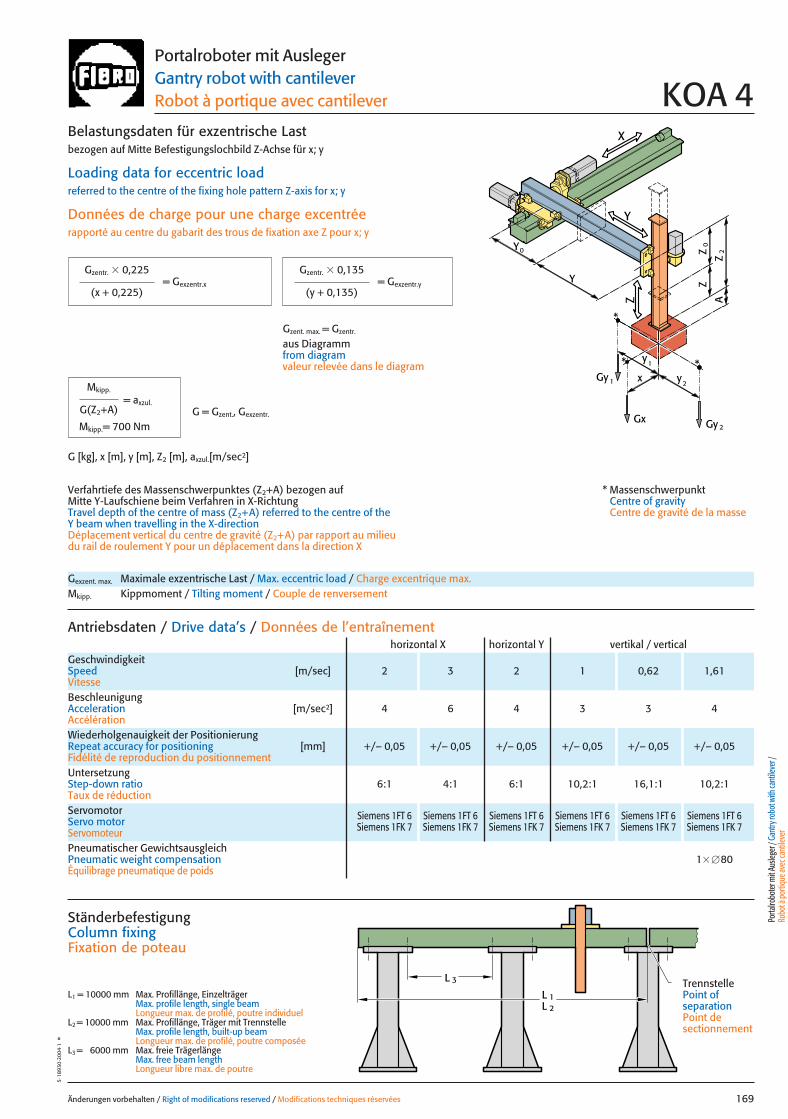
X
Y
Z
0Z
Z
2Z
A
x
Gy 2Gx
2y
1y *
Gy 1
Y
Y
0
*
*
Änderungen vorbehalten / Right of modifications reserved / Modifications techniques réservées 169
5·18
930
·200
4·1
°Portalroboter mit AuslegerGantry robot with cantileverRobot à portique avec cantilever KOA 4
Gexzent. max. Maximale exzentrische Last / Max. eccentric load / Charge excentrique max.Mkipp. Kippmoment / Tilting moment / Couple de renversement
Antriebsdaten / Drive data’s / Données de l’entraînement
GeschwindigkeitSpeed [m/sec] 2 3 2 1 0,62 1,61Vitesse
horizontal X horizontal Y vertikal / vertical
Wiederholgenauigkeit der PositionierungRepeat accuracy for positioning [mm] +/– 0,05 +/– 0,05 +/– 0,05 +/– 0,05 +/– 0,05 +/– 0,05Fidélité de reproduction du positionnement
BeschleunigungAcceleration [m/sec2] 4 6 4 3 3 4Accélération
Servomotor Siemens 1FT 6 Siemens 1FT 6 Siemens 1FT 6 Siemens 1FT 6 Siemens 1FT 6 Siemens 1FT 6Servo motor Siemens 1FK 7 Siemens 1FK 7 Siemens 1FK 7 Siemens 1FK 7 Siemens 1FK 7 Siemens 1FK 7Servomoteur
UntersetzungStep-down ratio 6:1 4:1 6:1 10,2:1 16,1:1 10,2:1Taux de réduction
= Gexzentr.y
Belastungsdaten für exzentrische Lastbezogen auf Mitte Befestigungslochbild Z-Achse für x; y
Loading data for eccentric loadreferred to the centre of the fixing hole pattern Z-axis for x; y
Données de charge pour une charge excentréerapporté au centre du gabarit des trous de fixation axe Z pour x; y
Verfahrtiefe des Massenschwerpunktes (Z2+A) bezogen auf Mitte Y-Laufschiene beim Verfahren in X-RichtungTravel depth of the centre of mass (Z2+A) referred to the centre of the Y beam when travelling in the X-directionDéplacement vertical du centre de gravité (Z2+A) par rapport au milieudu rail de roulement Y pour un déplacement dans la direction X
G [kg], x [m], y [m], Z2 [m], axzul.[m/sec2]
= Gexzentr.x
Gzentr. � 0,225
(x + 0,225)
Gzentr. � 0,135
(y + 0,135)
Gzent. max. = Gzentr.
aus Diagrammfrom diagramvaleur relevée dans le diagram
* MassenschwerpunktCentre of gravityCentre de gravité de la masse
= axzul.
Mkipp.
G(Z2+A)
Mkipp.= 700 NmG = Gzent., Gexzentr.
L 3
L 1L 2
Ständerbefestigung Column fixingFixation de poteau
L1 = 10000 mm Max. Profillänge, EinzelträgerMax. profile length, single beam Longueur max. de profilé, poutre individuel
L2 = 10000 mm Max. Profillänge, Träger mit TrennstelleMax. profile length, built-up beam Longueur max. de profilé, poutre composée
L3 = 6000 mm Max. freie TrägerlängeMax. free beam length Longueur libre max. de poutre
TrennstellePoint of separationPoint de sectionnement
Porta
lrobo
ter m
it Aus
leger
/ Gan
try ro
bot w
ith ca
ntile
ver /
Ro
bot à
porti
que a
vec c
antile
ver
Pneumatischer GewichtsausgleichPneumatic weight compensation 1� �80Équilibrage pneumatique de poids
169 27.08.2004 8:38 Uhr Seite 1
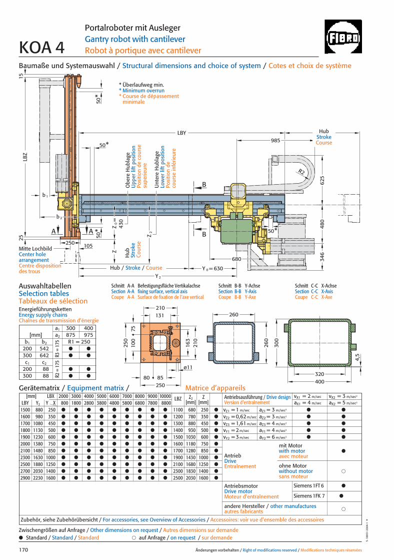
4,5
163
7510
0
80 85
131
630
LBY985
B
B
50*
50*
680
Y 0 =Y 2
480
346
R2
260
260
300
400320
210
250
210
250
ø11
b1
b2
Z
LBZ
Z2
Z0=
A A
50*
50*
1525
105250
625
430
Baumaße und Systemauswahl / Structural dimensions and choice of system / Cotes et choix de système
Schnitt A-A Befestigungsfläche VertikalachseSection A-A fixing surface, vertical axisCoupe A-A Surface de fixation de l’axe vertical
Schnitt B-B Y-AchseSection B-B Y-AxisCoupe B-B Y-Axe
Schnitt C-C X-AchseSection C-C X-AxisCoupe C-C X-Axe
AuswahltabellenSelection tablesTableaux de sélectionEnergieführungskettenEnergy supply chainsChaînes de transmission d’énergie
Änderungen vorbehalten / Right of modifications reserved / Modifications techniques réservées170
5·18
931·
2004
·1°
Portalroboter mit AuslegerGantry robot with cantileverRobot à portique avec cantileverKOA 4
Hub
Stro
keC
ours
eHub
StrokeCourse
Hub / Stroke / Course
Unt
ere
Hub
lage
Low
er li
ft p
ositi
onPo
sitio
n de
co
urse
infé
rieur
e
Obe
re H
ubla
geU
pper
lift
pos
ition
Posi
tion
de c
ours
e su
perie
ure
* Überlaufweg min.* Minimum overrun* Course de dépassement
minimale
[mm] LBX 2000 3000 4000 5000 6000 7000 8000 9000 10000 LBZ Z2 ZLBY Y2 Y X 800 1800 2800 3800 4800 5800 6800 7800 8800 [mm] [mm]
1500 880 250 ● ● ● ● ● ● ● ● ● 1100 680 250 ●
1600 980 350 ● ● ● ● ● ● ● ● ● 1200 780 350 ●
1700 1080 450 ● ● ● ● ● ● ● ● ● 1300 880 450 ●
1800 1130 500 ● ● ● ● ● ● ● ● ● 1400 930 500 ●
1900 1230 600 ● ● ● ● ● ● ● ● ● 1500 1030 600 ●
2000 1380 750 ● ● ● ● ● ● ● ● ● 1600 1180 750 ●
2100 1480 850 ● ● ● ● ● ● ● ● ● 1700 1280 850 ●
2300 1630 1000 ● ● ● ● ● ● ● ● ● 1900 1430 1000 ●
2500 1880 1250 ● ● ● ● ● ● ● ● ● 2100 1680 1250 ●
2700 2030 1400 ● ● ● ● ● ● ● ● ● 2300 1830 1400 ●
2900 2230 1600 ● ● ● ● ● ● ● ● ● 2500 2030 1600 ●
Antriebsausführung / Drive design Version d’entraînement
vX1 = 2 m/sec vX2 = 3 m/sec2
aX1 = 4 m/sec aX2 = 5 m/sec2
vZ1 = 1 m/sec aZ1 = 3 m/sec2 ● ●
vZ2 = 0,62 m/sec aZ2 = 3 m/sec2 ● ●
vZ3 = 1,61 m/sec aZ3 = 4 m/sec2 ● ●
vY1 = 2 m/sec aY1 = 4 m/sec2 ● ●
vY2 = 3 m/sec aY2 = 6 m/sec2 ● ●
AntriebDriveEntraînement
AntriebsmotorDrive motorMoteur d’entraînement
�andere Hersteller / other manufacturesautres fabricants
Zubehör, siehe Zubehörübersicht / For accessories, see Overview of Accessories / Accessoires: voir vue d’ensemble des accessoires
mit Motorwith motoravec moteur
●
�ohne Motorwithout motorsans moteur
Gerätematrix / Equipment matrix / Matrice d’appareils
a1 300 400[mm] a2 875 975
b1 b2 R1 = 250200 542 ● ●
300 642 ● ●
c1 c2
200 88 ● ●
300 88 ● ●
● Standard / Standard / Standard � auf Anfrage / on request / sur demandeZwischengrößen auf Anfrage / Other dimensions on request / Autres dimensions sur demande
R3 =
175
R2 =
175
Mitte LochbildCenter hole arrangementCentre disposition des trous
Siemens 1FT 6 ●
Siemens 1FK 7 ●
170 27.08.2004 8:38 Uhr Seite 2
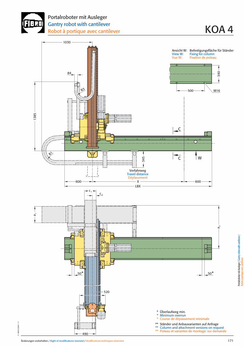
500
LBXX
520
W
50* 50*
340
c 1
a 1
M16
a 2
c 2
490
C
C
600 600
345
1030
1385
84
R1
R3
Änderungen vorbehalten / Right of modifications reserved / Modifications techniques réservées 171
5·18
932·
2004
·1°
Portalroboter mit AuslegerGantry robot with cantileverRobot à portique avec cantilever KOA 4
Ansicht W: Befestigungsfläche für StänderView W: Fixing for columnVue W: Fixation de poteau
VerfahrwegTravel distanceDéplacement
Porta
lrobo
ter m
it Aus
leger
/ Gan
try ro
bot w
ith ca
ntile
ver /
Ro
bot à
porti
que a
vec c
antile
ver
* Überlaufweg min.* Minimum overrun* Course de dépassement minimale
** Ständer und Anbauvarianten auf Anfrage** Column and attachment versions on request** Poteau et variantes de montage: sur demande
171 27.08.2004 8:38 Uhr Seite 1
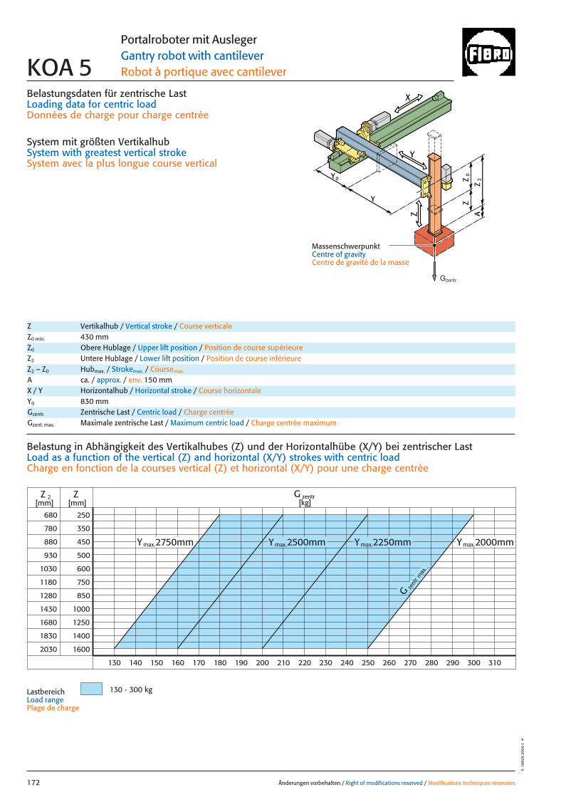
Belastungsdaten für zentrische LastLoading data for centric loadDonnées de charge pour charge centrée
System mit größten VertikalhubSystem with greatest vertical strokeSystem avec la plus longue course vertical
2250mmY
zent
r
G
max
.
680
780
880
930
1030
1180
1280
1430
1680
1830
2030
250
350
450
500
600
750
850
1000
1250
1400
1600
Z
130 140 150 160 170 180 190 200 210 220 230 240 250 260 270 280 290 300 310
Z 2 G zentr[kg][mm] [mm]
130 - 300 kg
Ymax.2750mm Ymax.2000mmYmax.max.2500mm
Änderungen vorbehalten / Right of modifications reserved / Modifications techniques réservées172
5·18
929
·200
4·1
°
Portalroboter mit AuslegerGantry robot with cantileverRobot à portique avec cantileverKOA 5
Z Vertikalhub / Vertical stroke / Course verticaleZ0 min. 430 mmZ0 Obere Hublage / Upper lift position / Position de course supérieureZ2 Untere Hublage / Lower lift position / Position de course inférieureZ2 – Z0 Hubmax. / Strokemax. / Coursemax.
A ca. / approx. / env. 150 mm
Gzentr. Zentrische Last / Centric load / Charge centréeGzent. max. Maximale zentrische Last / Maximum centric load / Charge centrée maximum
X / Y Horizontalhub / Horizontal stroke / Course horizontaleY0 830 mm
Belastung in Abhängigkeit des Vertikalhubes (Z) und der Horizontalhübe (X/Y) bei zentrischer Last Load as a function of the vertical (Z) and horizontal (X/Y) strokes with centric loadCharge en fonction de la courses vertical (Z) et horizontal (X/Y) pour une charge centrée
LastbereichLoad range Plage de charge
X
Y
Z
0Z
Z
2Z
A
Y
Y
0
MassenschwerpunktCentre of gravityCentre de gravité de la masse
Gzentr.
172 27.08.2004 8:04 Uhr Seite 2

X
Y
Z
0Z
Z
2Z
A
x
Gy 2Gx
2y
1y *
Gy 1
Y
Y
0
*
*
Änderungen vorbehalten / Right of modifications reserved / Modifications techniques réservées 173
5·18
930
·200
4·1
°Portalroboter mit AuslegerGantry robot with cantileverRobot à portique avec cantilever KOA 5
Gexzent. max. Maximale exzentrische Last / Max. eccentric load / Charge excentrique max.Mkipp. Kippmoment / Tilting moment / Couple de renversement
Antriebsdaten / Drive data’s / Données de l’entraînement
GeschwindigkeitSpeed [m/sec] 2 3 2 3 1 0,62 1,61Vitesse
horizontal X horizontal Y vertikal / vertical
Wiederholgenauigkeit der PositionierungRepeat accuracy for positioning [mm] +/– 0,05 +/– 0,05 +/– 0,05 +/– 0,05 +/– 0,05 +/– 0,05 +/– 0,05Fidélité de reproduction du positionnement
BeschleunigungAcceleration [m/sec2] 4 5 4 6 3 3 4Accélération
Servomotor Siemens 1FT 6 Siemens 1FT 6 Siemens 1FT 6 Siemens 1FT 6 Siemens 1FT 6 Siemens 1FT 6 Siemens 1FT 6Servo motor Siemens 1FK 7 Siemens 1FK 7 Siemens 1FK 7 Siemens 1FK 7 Siemens 1FK 7 Siemens 1FK 7 Siemens 1FK 7Servomoteur
UntersetzungStep-down ratio 6:1 4:1 6:1 4:1 10,2:1 16,1:1 10,2:1Taux de réduction
= Gexzentr.y
Belastungsdaten für exzentrische Lastbezogen auf Mitte Befestigungslochbild Z-Achse für x; y
Loading data for eccentric loadreferred to the centre of the fixing hole pattern Z-axis for x; y
Données de charge pour une charge excentréerapporté au centre du gabarit des trous de fixation axe Z pour x; y
Verfahrtiefe des Massenschwerpunktes (Z2+A) bezogen auf Mitte Y-Laufschiene beim Verfahren in X-RichtungTravel depth of the centre of mass (Z2+A) referred to the centre of the Y beam when travelling in the X-directionDéplacement vertical du centre de gravité (Z2+A) par rapport au milieudu rail de roulement Y pour un déplacement dans la direction X
G [kg], x [m], y [m], Z2 [m], axzul.[m/sec2]
= Gexzentr.x
Gzentr. � 0,225
(x + 0,225)
Gzentr. � 0,135
(y + 0,135)
Gzent. max. = Gzentr.
aus Diagrammfrom diagramvaleur relevée dans le diagram
* MassenschwerpunktCentre of gravityCentre de gravité de la masse
= axzul.
Mkipp.
G(Z2+A)
Mkipp.= 700 NmG = Gzent., Gexzentr.
L 3
L 1L 2
Ständerbefestigung Column fixingFixation de poteau
L1 = 10000 mm Max. Profillänge, EinzelträgerMax. profile length, single beam Longueur max. de profilé, poutre individuel
L2 = 10000 mm Max. Profillänge, Träger mit TrennstelleMax. profile length, built-up beam Longueur max. de profilé, poutre composée
L3 = 6000 mm Max. freie TrägerlängeMax. free beam length Longueur libre max. de poutre
TrennstellePoint of separationPoint de sectionnement
Porta
lrobo
ter m
it Aus
leger
/ Gan
try ro
bot w
ith ca
ntile
ver /
Ro
bot à
porti
que a
vec c
antile
ver
Pneumatischer GewichtsausgleichPneumatic weight compensation 1� �80Équilibrage pneumatique de poids
173 27.08.2004 8:05 Uhr Seite 1
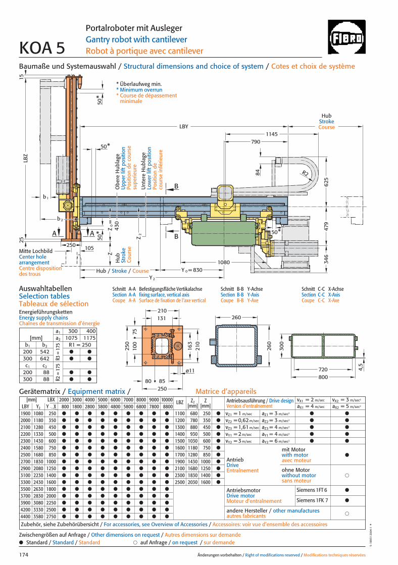
830
300
720800
1145LBY
Y
LBZ
A A
50*
50*
1525
105
b1
b2
Z
Z2
Z0=
B
B250
50*
260
260
Y 0 =
2
R2
50*
625
479
346
430
108084
163
7510
0
80 85
131
210
250
210
250
ø11 4,5
790
Baumaße und Systemauswahl / Structural dimensions and choice of system / Cotes et choix de système
Schnitt A-A Befestigungsfläche VertikalachseSection A-A fixing surface, vertical axisCoupe A-A Surface de fixation de l’axe vertical
Schnitt B-B Y-AchseSection B-B Y-AxisCoupe B-B Y-Axe
Schnitt C-C X-AchseSection C-C X-AxisCoupe C-C X-Axe
AuswahltabellenSelection tablesTableaux de sélectionEnergieführungskettenEnergy supply chainsChaînes de transmission d’énergie
Änderungen vorbehalten / Right of modifications reserved / Modifications techniques réservées174
5·18
931·
2004
·1°
Portalroboter mit AuslegerGantry robot with cantileverRobot à portique avec cantileverKOA 5
Hub
Stro
keC
ours
e
HubStrokeCourse
Hub / Stroke / Course
Unt
ere
Hub
lage
Low
er li
ft p
ositi
onPo
sitio
n de
co
urse
infé
rieur
e
Obe
re H
ubla
geU
pper
lift
pos
ition
Posi
tion
de c
ours
e su
perie
ure
* Überlaufweg min.* Minimum overrun* Course de dépassement
minimale
[mm] LBX 2000 3000 4000 5000 6000 7000 8000 9000 10000 LBZ Z2 ZLBY Y2 Y X 800 1800 2800 3800 4800 5800 6800 7800 8800 [mm] [mm]
1900 1080 250 ● ● ● ● ● ● ● ● ● 1100 680 250 ●
2000 1180 350 ● ● ● ● ● ● ● ● ● 1200 780 350 ●
2100 1280 450 ● ● ● ● ● ● ● ● ● 1300 880 450 ●
2200 1330 500 ● ● ● ● ● ● ● ● ● 1400 930 500 ●
2300 1430 600 ● ● ● ● ● ● ● ● ● 1500 1030 600 ●
2400 1580 750 ● ● ● ● ● ● ● ● ● 1600 1180 750 ●
2500 1680 850 ● ● ● ● ● ● ● ● ● 1700 1280 850 ●
2700 1830 1000 ● ● ● ● ● ● ● ● ● 1900 1430 1000 ●
2900 2080 1250 ● ● ● ● ● ● ● ● ● 2100 1680 1250 ●
3100 2230 1400 ● ● ● ● ● ● ● ● ● 2300 1830 1400 ●
3300 2430 1600 ● ● ● ● ● ● ● ● ● 2500 2030 1600 ●
3500 2630 1800 ● ● ● ● ● ● ● ● ●
3700 2830 2000 ● ● ● ● ● ● ● ● ●
3900 3080 2250 ● ● ● ● ● ● ● ● ●
4200 3330 2500 ● ● ● ● ● ● ● ● ●
4400 3580 2750 ● ● ● ● ● ● ● ● ●
Antriebsausführung / Drive design Version d’entraînement
vX1 = 2 m/sec vX2 = 3 m/sec2
aX1 = 4 m/sec aX2 = 5 m/sec2
vZ1 = 1 m/sec aZ1 = 3 m/sec2 ● ●
vZ2 = 0,62 m/sec aZ2 = 3 m/sec2 ● ●
vZ3 = 1,61 m/sec aZ3 = 4 m/sec2 ● ●
vY1 = 2 m/sec aY1 = 4 m/sec2 ● ●
vY2 = 3 m/sec aY2 = 6 m/sec2 ● ●
AntriebDriveEntraînement
AntriebsmotorDrive motorMoteur d’entraînement
�andere Hersteller / other manufacturesautres fabricants
Zubehör, siehe Zubehörübersicht / For accessories, see Overview of Accessories / Accessoires: voir vue d’ensemble des accessoires
mit Motorwith motoravec moteur
●
�ohne Motorwithout motorsans moteur
Gerätematrix / Equipment matrix / Matrice d’appareils
a1 300 400[mm] a2 1075 1175
b1 b2 R1 = 250200 542 ● ●
300 642 ● ●
c1 c2
200 88 ● ●
300 88 ● ●
● Standard / Standard / Standard � auf Anfrage / on request / sur demandeZwischengrößen auf Anfrage / Other dimensions on request / Autres dimensions sur demande
R3 =
175
R2 =
175
Mitte LochbildCenter hole arrangementCentre disposition des trous
Siemens 1FT 6 ●
Siemens 1FK 7 ●
174 27.08.2004 8:05 Uhr Seite 2
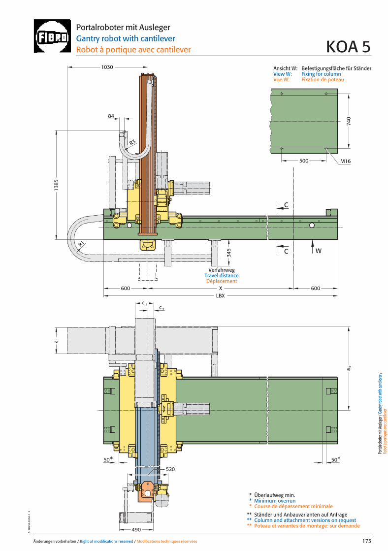
740
LBXX
W
C
C
50* 50*520
500 M16
R3
R1
a 1
a 2
c 1c 2
490
600 600
345
1385
1030
84
Änderungen vorbehalten / Right of modifications reserved / Modifications techniques réservées 175
5·18
932·
2004
·1°
Portalroboter mit AuslegerGantry robot with cantileverRobot à portique avec cantilever KOA 5
Ansicht W: Befestigungsfläche für StänderView W: Fixing for columnVue W: Fixation de poteau
VerfahrwegTravel distanceDéplacement
Porta
lrobo
ter m
it Aus
leger
/ Gan
try ro
bot w
ith ca
ntile
ver /
Ro
bot à
porti
que a
vec c
antile
ver
* Überlaufweg min.* Minimum overrun* Course de dépassement minimale
** Ständer und Anbauvarianten auf Anfrage** Column and attachment versions on request** Poteau et variantes de montage: sur demande
175 27.08.2004 8:05 Uhr Seite 1
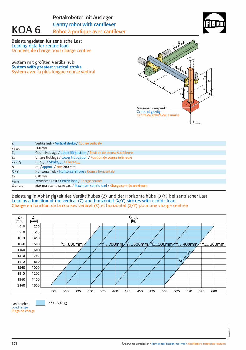
Belastungsdaten für zentrische LastLoading data for centric loadDonnées de charge pour charge centrée
System mit größten VertikalhubSystem with greatest vertical strokeSystem avec la plus longue course vertical
810
910
1010
1060
1160
1310
1410
1560
1810
1960
2160
250
350
450
500
600
750
850
1000
1250
1400
1600
ZZ 2[mm] [mm]
G zentr[kg]
270 - 600 kg
300 350 400 450 500 550 600325275 375 425 475 525 575
G zent
r max
.
Ymax.300mmYmax.400mmYmax.500mmYmax.600mmYmax.700mmYmax.800mm
Änderungen vorbehalten / Right of modifications reserved / Modifications techniques réservées176
5·18
929
·200
4·1
°
Portalroboter mit AuslegerGantry robot with cantileverRobot à portique avec cantileverKOA 6
Z Vertikalhub / Vertical stroke / Course verticaleZ0 min. 560 mmZ0 Obere Hublage / Upper lift position / Position de course supérieureZ2 Untere Hublage / Lower lift position / Position de course inférieureZ2 – Z0 Hubmax. / Strokemax. / Coursemax.
A ca. / approx. / env. 200 mm
Gzentr. Zentrische Last / Centric load / Charge centréeGzent. max. Maximale zentrische Last / Maximum centric load / Charge centrée maximum
X / Y Horizontalhub / Horizontal stroke / Course horizontaleY0 630 mm
Belastung in Abhängigkeit des Vertikalhubes (Z) und der Horizontalhübe (X/Y) bei zentrischer Last Load as a function of the vertical (Z) and horizontal (X/Y) strokes with centric loadCharge en fonction de la courses vertical (Z) et horizontal (X/Y) pour une charge centrée
LastbereichLoad range Plage de charge
X
Y
Z
0Z
Z
2Z
A
Y
Y
0
MassenschwerpunktCentre of gravityCentre de gravité de la masse
Gzentr.
176 27.08.2004 8:38 Uhr Seite 2

X
Y
Z
0Z
Z
2Z
A
x
Gy 2Gx
2y
1y *
Gy 1
Y
Y
0
*
*
Änderungen vorbehalten / Right of modifications reserved / Modifications techniques réservées 177
5·18
930
·200
4·1
°Portalroboter mit AuslegerGantry robot with cantileverRobot à portique avec cantilever KOA 6
Gexzent. max. Maximale exzentrische Last / Max. eccentric load / Charge excentrique max.Mkipp. Kippmoment / Tilting moment / Couple de renversement
Antriebsdaten / Drive data’s / Données de l’entraînement
GeschwindigkeitSpeed [m/sec] 2 3 2 1 0,55 1,6Vitesse
horizontal X horizontal Y vertikal / vertical
Wiederholgenauigkeit der PositionierungRepeat accuracy for positioning [mm] +/– 0,05 +/– 0,05 +/– 0,05 +/– 0,05 +/– 0,05 +/– 0,05Fidélité de reproduction du positionnement
BeschleunigungAcceleration [m/sec2] 4 4 4 3 3 4Accélération
Servomotor Siemens 1FT 6 Siemens 1FT 6 Siemens 1FT 6 Siemens 1FT 6 Siemens 1FT 6 Siemens 1FT 6Servo motor Siemens 1FK 7 Siemens 1FK 7 Siemens 1FK 7 Siemens 1FK 7 Siemens 1FK 7 Siemens 1FK 7Servomoteur
UntersetzungStep-down ratio 6:1 4:1 6:1 12,4:1 24,1:1 12,4:1Taux de réduction
= Gexzentr.y
Belastungsdaten für exzentrische Lastbezogen auf Mitte Befestigungslochbild Z-Achse für x; y
Loading data for eccentric loadreferred to the centre of the fixing hole pattern Z-axis for x; y
Données de charge pour une charge excentréerapporté au centre du gabarit des trous de fixation axe Z pour x; y
Verfahrtiefe des Massenschwerpunktes (Z2+A) bezogen auf Mitte Y-Laufschiene beim Verfahren in X-RichtungTravel depth of the centre of mass (Z2+A) referred to the centre of the Y beam when travelling in the X-directionDéplacement vertical du centre de gravité (Z2+A) par rapport au milieudu rail de roulement Y pour un déplacement dans la direction X
G [kg], x [m], y [m], Z2 [m], axzul.[m/sec2]
= Gexzentr.x
Gzentr. � 0,27
(x + 0,27)
Gzentr. � 0,22
(y + 0,22)
Gzent. max. = Gzentr.
aus Diagrammfrom diagramvaleur relevée dans le diagram
* MassenschwerpunktCentre of gravityCentre de gravité de la masse
= axzul.
Mkipp.
G(Z2+A)
Mkipp.= 1400 NmG = Gzent., Gexzentr.
L 3
L 1L 2
Ständerbefestigung Column fixingFixation de poteau
L1 = 10000 mm Max. Profillänge, EinzelträgerMax. profile length, single beam Longueur max. de profilé, poutre individuel
L2 = 10000 mm Max. Profillänge, Träger mit TrennstelleMax. profile length, built-up beam Longueur max. de profilé, poutre composée
L3 = 6000 mm Max. freie TrägerlängeMax. free beam length Longueur libre max. de poutre
TrennstellePoint of separationPoint de sectionnement
Porta
lrobo
ter m
it Aus
leger
/ Gan
try ro
bot w
ith ca
ntile
ver /
Ro
bot à
porti
que a
vec c
antile
ver
Pneumatischer GewichtsausgleichPneumatic weight compensation 1� �100Équilibrage pneumatique de poids
177 27.08.2004 8:38 Uhr Seite 1
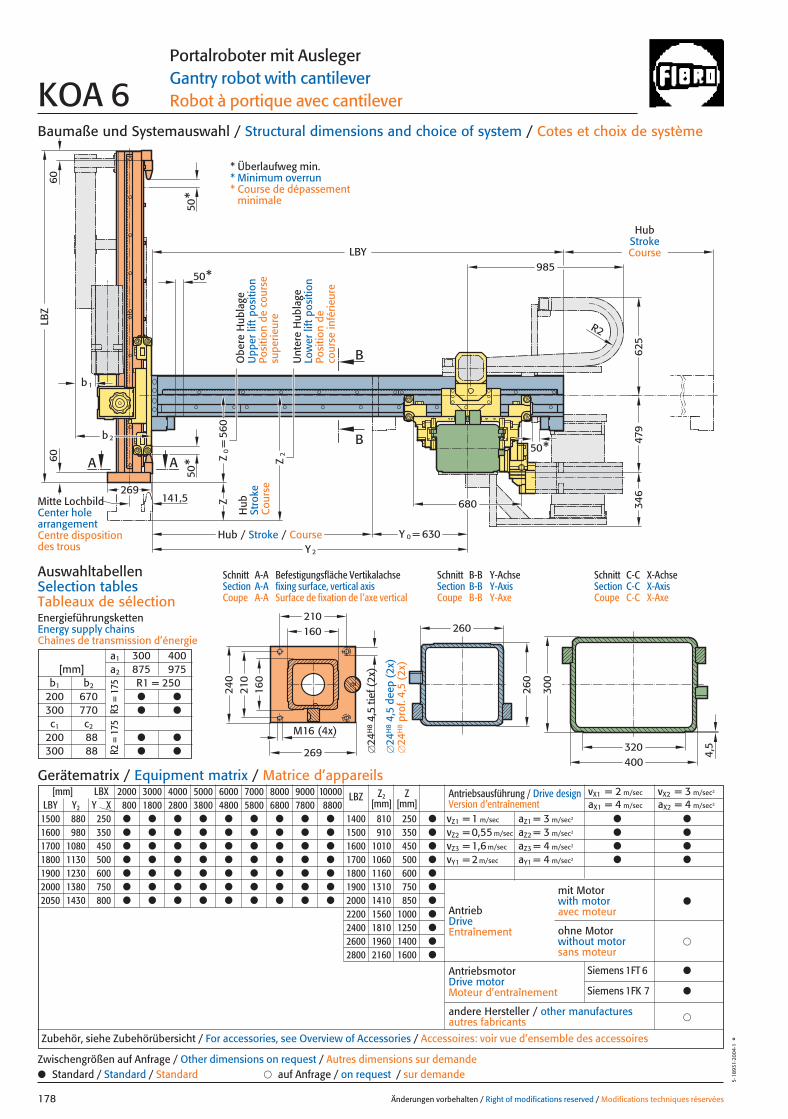
560
630
LBY985
Z
Z2
2b
b1
269
LBZ
A
50*
50*
141,5
B
B
Z0=
A
50*
50*
680
Y 0 =Y 2
479
346
R2
240
210
269
210
M16 (4x)
260
260
300
400320
625
4,5
160
160
6060
Baumaße und Systemauswahl / Structural dimensions and choice of system / Cotes et choix de système
Schnitt A-A Befestigungsfläche VertikalachseSection A-A fixing surface, vertical axisCoupe A-A Surface de fixation de l’axe vertical
Schnitt B-B Y-AchseSection B-B Y-AxisCoupe B-B Y-Axe
Schnitt C-C X-AchseSection C-C X-AxisCoupe C-C X-Axe
AuswahltabellenSelection tablesTableaux de sélectionEnergieführungskettenEnergy supply chainsChaînes de transmission d’énergie
Änderungen vorbehalten / Right of modifications reserved / Modifications techniques réservées178
5·18
931·
2004
·1°
Portalroboter mit AuslegerGantry robot with cantileverRobot à portique avec cantileverKOA 6
Hub
Stro
keC
ours
e
HubStrokeCourse
Hub / Stroke / Course
[mm] LBX 2000 3000 4000 5000 6000 7000 8000 9000 10000 LBZ Z2 ZLBY Y2 Y X 800 1800 2800 3800 4800 5800 6800 7800 8800 [mm] [mm]
1500 880 250 ● ● ● ● ● ● ● ● ● 1400 810 250 ●
1600 980 350 ● ● ● ● ● ● ● ● ● 1500 910 350 ●
1700 1080 450 ● ● ● ● ● ● ● ● ● 1600 1010 450 ●
1800 1130 500 ● ● ● ● ● ● ● ● ● 1700 1060 500 ●
1900 1230 600 ● ● ● ● ● ● ● ● ● 1800 1160 600 ●
2000 1380 750 ● ● ● ● ● ● ● ● ● 1900 1310 750 ●
2050 1430 800 ● ● ● ● ● ● ● ● ● 2000 1410 850 ●
2200 1560 1000 ●
2400 1810 1250 ●
2600 1960 1400 ●
2800 2160 1600 ●
Antriebsausführung / Drive design Version d’entraînement
vX1 = 2 m/sec vX2 = 3 m/sec2
aX1 = 4 m/sec aX2 = 4 m/sec2
vZ1 = 1 m/sec aZ1 = 3 m/sec2 ● ●
vZ2 = 0,55 m/sec aZ2 = 3 m/sec2 ● ●
vZ3 = 1,6 m/sec aZ3 = 4 m/sec2 ● ●
vY1 = 2 m/sec aY1 = 4 m/sec2 ● ●
AntriebDriveEntraînement
AntriebsmotorDrive motorMoteur d’entraînement
�andere Hersteller / other manufacturesautres fabricants
Zubehör, siehe Zubehörübersicht / For accessories, see Overview of Accessories / Accessoires: voir vue d’ensemble des accessoires
mit Motorwith motoravec moteur
●
�ohne Motorwithout motorsans moteur
Gerätematrix / Equipment matrix / Matrice d’appareils
a1 300 400[mm] a2 875 975
b1 b2 R1 = 250200 670 ● ●
300 770 ● ●
c1 c2
200 88 ● ●
300 88 ● ●
● Standard / Standard / Standard � auf Anfrage / on request / sur demandeZwischengrößen auf Anfrage / Other dimensions on request / Autres dimensions sur demande
R3 =
175
R2 =
175
Mitte LochbildCenter hole arrangementCentre disposition des trous
* Überlaufweg min.* Minimum overrun* Course de dépassement
minimale
Unt
ere
Hub
lage
Low
er li
ft p
ositi
onPo
sitio
n de
co
urse
infé
rieur
e
Obe
re H
ubla
geU
pper
lift
pos
ition
Posi
tion
de c
ours
e su
perie
ure
�24
H8
4,5
tief (
2x)
�24
H8
4,5
deep
(2x
)�
24H
8pr
of. 4
,5 (
2x)
Siemens 1FT 6 ●
Siemens 1FK 7 ●
178 27.08.2004 8:38 Uhr Seite 2
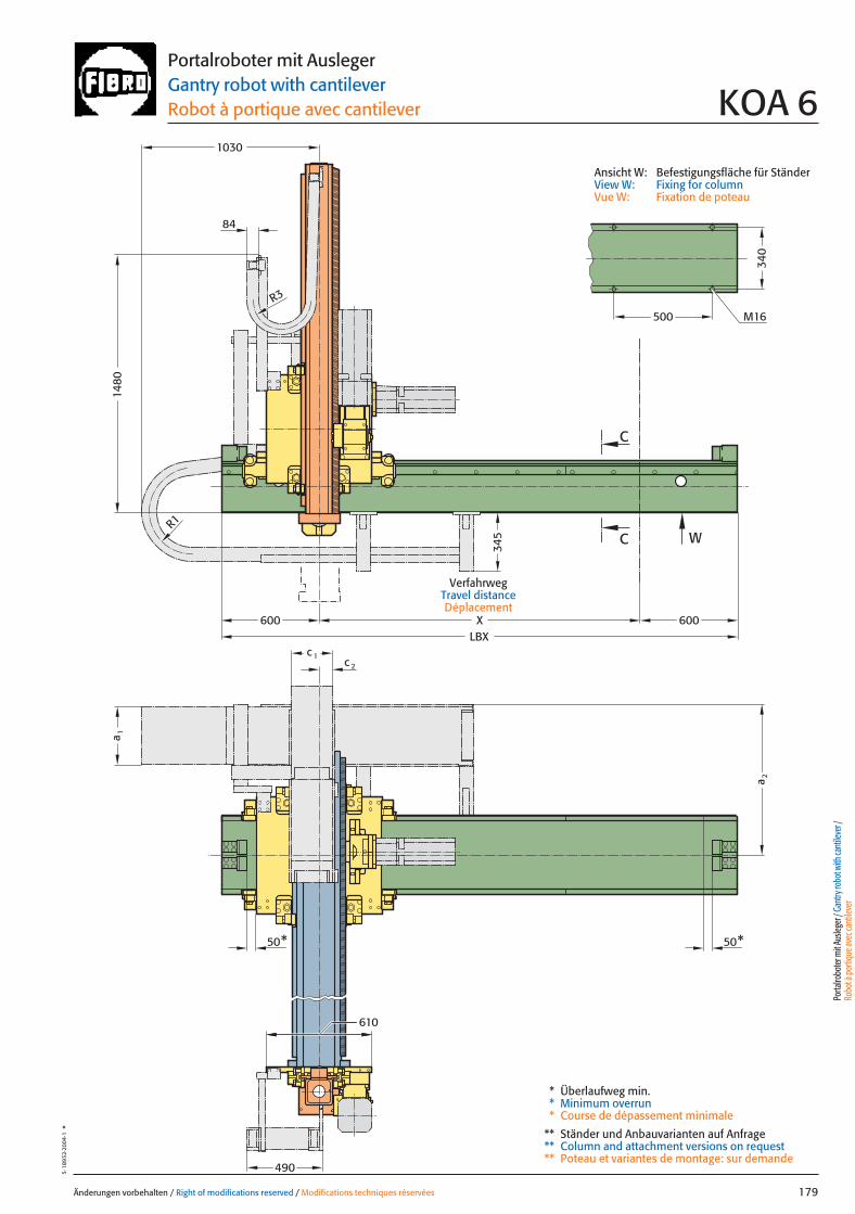
500
600LBX
X
50* 50*
610
W
C
C
600
1030
1480
84
R3
R1
340
490
c 1
a 1
M16
a 2
c 2
345
Änderungen vorbehalten / Right of modifications reserved / Modifications techniques réservées 179
5·18
932·
2004
·1°
Portalroboter mit AuslegerGantry robot with cantileverRobot à portique avec cantilever KOA 6
Ansicht W: Befestigungsfläche für StänderView W: Fixing for columnVue W: Fixation de poteau
VerfahrwegTravel distanceDéplacement
Porta
lrobo
ter m
it Aus
leger
/ Gan
try ro
bot w
ith ca
ntile
ver /
Ro
bot à
porti
que a
vec c
antile
ver
* Überlaufweg min.* Minimum overrun* Course de dépassement minimale
** Ständer und Anbauvarianten auf Anfrage** Column and attachment versions on request** Poteau et variantes de montage: sur demande
179 27.08.2004 8:39 Uhr Seite 1
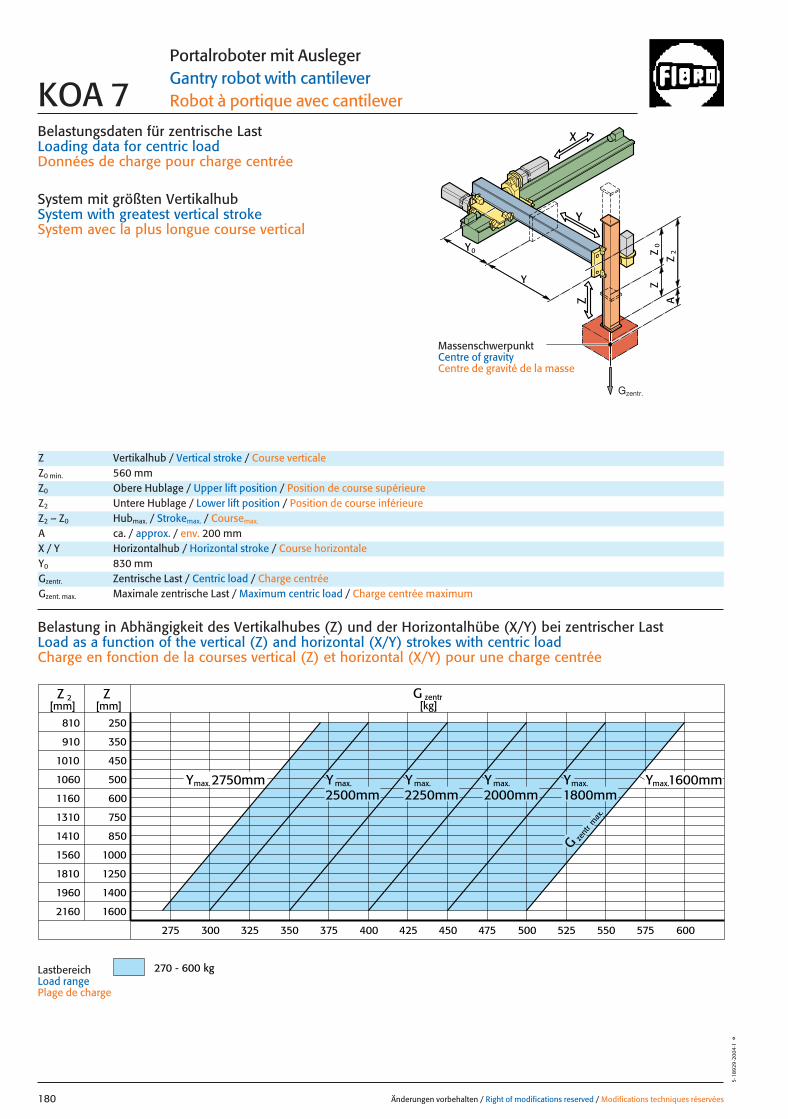
Belastungsdaten für zentrische LastLoading data for centric loadDonnées de charge pour charge centrée
System mit größten VertikalhubSystem with greatest vertical strokeSystem avec la plus longue course vertical
810
910
1010
1060
1160
1310
1410
1560
1810
1960
2160
250
350
450
500
600
750
850
1000
1250
1400
1600
ZZ 2[mm] [mm]
G zentr[kg]
270 - 600 kg
300 350 400 450 500 550 600325275 375 425 475 525 575
G zent
r max
.
Ymax.1600mmY max.
2500mmY max.
2250mmY max.
2000mmYmax.
1800mmmax.2750mmY
Änderungen vorbehalten / Right of modifications reserved / Modifications techniques réservées180
5·18
929
·200
4·1
°
Portalroboter mit AuslegerGantry robot with cantileverRobot à portique avec cantileverKOA 7
Z Vertikalhub / Vertical stroke / Course verticaleZ0 min. 560 mmZ0 Obere Hublage / Upper lift position / Position de course supérieureZ2 Untere Hublage / Lower lift position / Position de course inférieureZ2 – Z0 Hubmax. / Strokemax. / Coursemax.
A ca. / approx. / env. 200 mm
Gzentr. Zentrische Last / Centric load / Charge centréeGzent. max. Maximale zentrische Last / Maximum centric load / Charge centrée maximum
X / Y Horizontalhub / Horizontal stroke / Course horizontaleY0 830 mm
Belastung in Abhängigkeit des Vertikalhubes (Z) und der Horizontalhübe (X/Y) bei zentrischer Last Load as a function of the vertical (Z) and horizontal (X/Y) strokes with centric loadCharge en fonction de la courses vertical (Z) et horizontal (X/Y) pour une charge centrée
LastbereichLoad range Plage de charge
X
Y
Z
0Z
Z
2Z
A
Y
Y
0
MassenschwerpunktCentre of gravityCentre de gravité de la masse
Gzentr.
180 27.08.2004 8:05 Uhr Seite 2

X
Y
Z
0Z
Z
2Z
A
x
Gy 2Gx
2y
1y *
Gy 1
Y
Y
0
*
*
Änderungen vorbehalten / Right of modifications reserved / Modifications techniques réservées 181
5·18
930
·200
4·1
°Portalroboter mit AuslegerGantry robot with cantileverRobot à portique avec cantilever KOA 7
Gexzent. max. Maximale exzentrische Last / Max. eccentric load / Charge excentrique max.Mkipp. Kippmoment / Tilting moment / Couple de renversement
Antriebsdaten / Drive data’s / Données de l’entraînement
GeschwindigkeitSpeed [m/sec] 2 3 2 3 1 0,55 1,6Vitesse
horizontal X horizontal Y vertikal / vertical
Wiederholgenauigkeit der PositionierungRepeat accuracy for positioning [mm] +/– 0,05 +/– 0,05 +/– 0,05 +/– 0,05 +/– 0,05 +/– 0,05 +/– 0,05Fidélité de reproduction du positionnement
BeschleunigungAcceleration [m/sec2] 4 4 4 6 3 3 4Accélération
Servomotor Siemens 1FT 6 Siemens 1FT 6 Siemens 1FT 6 Siemens 1FT 6 Siemens 1FT 6 Siemens 1FT 6 Siemens 1FT 6Servo motor Siemens 1FK 7 Siemens 1FK 7 Siemens 1FK 7 Siemens 1FK 7 Siemens 1FK 7 Siemens 1FK 7 Siemens 1FK 7Servomoteur
UntersetzungStep-down ratio 6:1 4:1 6:1 4:1 12,4:1 24,1:1 12,4:1Taux de réduction
= Gexzentr.y
Belastungsdaten für exzentrische Lastbezogen auf Mitte Befestigungslochbild Z-Achse für x; y
Loading data for eccentric loadreferred to the centre of the fixing hole pattern Z-axis for x; y
Données de charge pour une charge excentréerapporté au centre du gabarit des trous de fixation axe Z pour x; y
Verfahrtiefe des Massenschwerpunktes (Z2+A) bezogen auf Mitte Y-Laufschiene beim Verfahren in X-RichtungTravel depth of the centre of mass (Z2+A) referred to the centre of the Y beam when travelling in the X-directionDéplacement vertical du centre de gravité (Z2+A) par rapport au milieudu rail de roulement Y pour un déplacement dans la direction X
G [kg], x [m], y [m], Z2 [m], axzul.[m/sec2]
= Gexzentr.x
Gzentr. � 0,27
(x + 0,27)
Gzentr. � 0,22
(y + 0,22)
Gzent. max. = Gzentr.
aus Diagrammfrom diagramvaleur relevée dans le diagram
* MassenschwerpunktCentre of gravityCentre de gravité de la masse
= axzul.
Mkipp.
G(Z2+A)
Mkipp.= 1400 NmG = Gzent., Gexzentr.
L 3
L 1L 2
Ständerbefestigung Column fixingFixation de poteau
L1 = 10000 mm Max. Profillänge, EinzelträgerMax. profile length, single beam Longueur max. de profilé, poutre individuel
L2 = 10000 mm Max. Profillänge, Träger mit TrennstelleMax. profile length, built-up beam Longueur max. de profilé, poutre composée
L3 = 6000 mm Max. freie TrägerlängeMax. free beam length Longueur libre max. de poutre
TrennstellePoint of separationPoint de sectionnement
Porta
lrobo
ter m
it Aus
leger
/ Gan
try ro
bot w
ith ca
ntile
ver /
Ro
bot à
porti
que a
vec c
antile
ver
Pneumatischer GewichtsausgleichPneumatic weight compensation 1� �100Équilibrage pneumatique de poids
181 27.08.2004 8:05 Uhr Seite 1
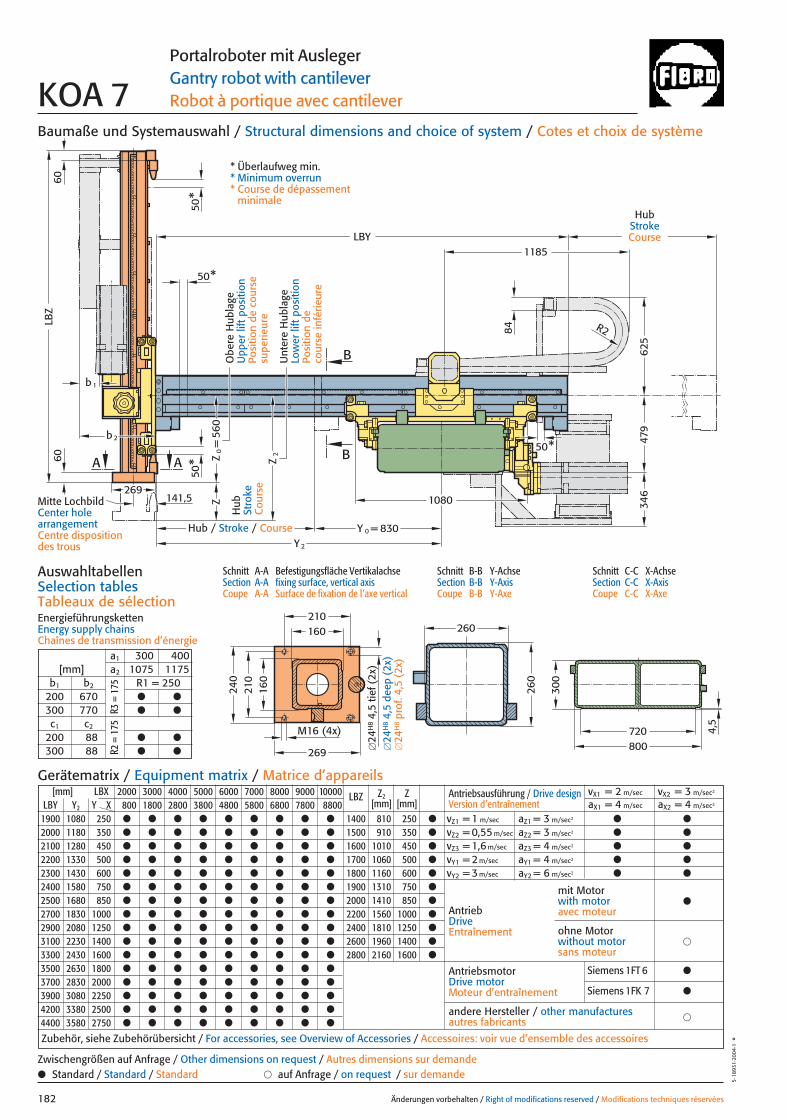
1080
830
LBY
Z2
LBZ
A
50*
50*
A
2b
b1
269141,5
B
B
Z
260
260
50*
R2
YY 0 =
2
50*
1185
479
625
560
Z=
0
346
84
300
720800
4,5
240
210
269
210
M16 (4x)
160
160
6060
Baumaße und Systemauswahl / Structural dimensions and choice of system / Cotes et choix de système
Schnitt A-A Befestigungsfläche VertikalachseSection A-A fixing surface, vertical axisCoupe A-A Surface de fixation de l’axe vertical
Schnitt B-B Y-AchseSection B-B Y-AxisCoupe B-B Y-Axe
Schnitt C-C X-AchseSection C-C X-AxisCoupe C-C X-Axe
AuswahltabellenSelection tablesTableaux de sélectionEnergieführungskettenEnergy supply chainsChaînes de transmission d’énergie
Änderungen vorbehalten / Right of modifications reserved / Modifications techniques réservées182
5·18
931·
2004
·1°
Portalroboter mit AuslegerGantry robot with cantileverRobot à portique avec cantileverKOA 7
Hub
Stro
keC
ours
e
HubStrokeCourse
Hub / Stroke / Course
[mm] LBX 2000 3000 4000 5000 6000 7000 8000 9000 10000 LBZ Z2 ZLBY Y2 Y X 800 1800 2800 3800 4800 5800 6800 7800 8800 [mm] [mm]
1900 1080 250 ● ● ● ● ● ● ● ● ● 1400 810 250 ●
2000 1180 350 ● ● ● ● ● ● ● ● ● 1500 910 350 ●
2100 1280 450 ● ● ● ● ● ● ● ● ● 1600 1010 450 ●
2200 1330 500 ● ● ● ● ● ● ● ● ● 1700 1060 500 ●
2300 1430 600 ● ● ● ● ● ● ● ● ● 1800 1160 600 ●
2400 1580 750 ● ● ● ● ● ● ● ● ● 1900 1310 750 ●
2500 1680 850 ● ● ● ● ● ● ● ● ● 2000 1410 850 ●
2700 1830 1000 ● ● ● ● ● ● ● ● ● 2200 1560 1000 ●
2900 2080 1250 ● ● ● ● ● ● ● ● ● 2400 1810 1250 ●
3100 2230 1400 ● ● ● ● ● ● ● ● ● 2600 1960 1400 ●
3300 2430 1600 ● ● ● ● ● ● ● ● ● 2800 2160 1600 ●
3500 2630 1800 ● ● ● ● ● ● ● ● ●
3700 2830 2000 ● ● ● ● ● ● ● ● ●
3900 3080 2250 ● ● ● ● ● ● ● ● ●
4200 3380 2500 ● ● ● ● ● ● ● ● ●
4400 3580 2750 ● ● ● ● ● ● ● ● ●
Antriebsausführung / Drive design Version d’entraînement
vX1 = 2 m/sec vX2 = 3 m/sec2
aX1 = 4 m/sec aX2 = 4 m/sec2
vZ1 = 1 m/sec aZ1 = 3 m/sec2 ● ●
vZ2 = 0,55 m/sec aZ2 = 3 m/sec2 ● ●
vZ3 = 1,6 m/sec aZ3 = 4 m/sec2 ● ●
vY1 = 2 m/sec aY1 = 4 m/sec2 ● ●
vY2 = 3 m/sec aY2 = 6 m/sec2 ● ●
AntriebDriveEntraînement
AntriebsmotorDrive motorMoteur d’entraînement
�andere Hersteller / other manufacturesautres fabricants
Zubehör, siehe Zubehörübersicht / For accessories, see Overview of Accessories / Accessoires: voir vue d’ensemble des accessoires
mit Motorwith motoravec moteur
●
�ohne Motorwithout motorsans moteur
Gerätematrix / Equipment matrix / Matrice d’appareils
a1 300 400[mm] a2 1075 1175
b1 b2 R1 = 250200 670 ● ●
300 770 ● ●
c1 c2
200 88 ● ●
300 88 ● ●
● Standard / Standard / Standard � auf Anfrage / on request / sur demandeZwischengrößen auf Anfrage / Other dimensions on request / Autres dimensions sur demande
R3 =
175
R2 =
175
Mitte LochbildCenter hole arrangementCentre disposition des trous
�24
H8
4,5
tief (
2x)
�24
H8
4,5
deep
(2x
)�
24H
8pr
of. 4
,5 (
2x)
Unt
ere
Hub
lage
Low
er li
ft p
ositi
onPo
sitio
n de
co
urse
infé
rieur
e
Obe
re H
ubla
geU
pper
lift
pos
ition
Posi
tion
de c
ours
e su
perie
ure
* Überlaufweg min.* Minimum overrun* Course de dépassement
minimale
Siemens 1FT 6 ●
Siemens 1FK 7 ●
182 27.08.2004 8:05 Uhr Seite 2

50* 50*610
LBX
W
X
C
C
500 M16
a 1
a 2
c 1c 2
R1
R3
600 600
740
1030
84
1480
345
490
Änderungen vorbehalten / Right of modifications reserved / Modifications techniques réservées 183
5·18
932·
2004
·1°
Portalroboter mit AuslegerGantry robot with cantileverRobot à portique avec cantilever KOA 7
Ansicht W: Befestigungsfläche für StänderView W: Fixing for columnVue W: Fixation de poteau
VerfahrwegTravel distanceDéplacement
Porta
lrobo
ter m
it Aus
leger
/ Gan
try ro
bot w
ith ca
ntile
ver /
Ro
bot à
porti
que a
vec c
antile
ver
* Überlaufweg min.* Minimum overrun* Course de dépassement minimale
** Ständer und Anbauvarianten auf Anfrage** Column and attachment versions on request** Poteau et variantes de montage: sur demande
183 27.08.2004 8:04 Uhr Seite 1

Änderungen vorbehalten / Right of modifications reserved / Modifications techniques réservées184
5·18
927·
2003
·1°
184 27.08.2004 8:39 Uhr Seite 2
Änderungen vorbehalten / Right of modifications reserved / Modifications techniques réservées 185
5·18
962·
2003
·1°
Zubehör und SicherheitssystemeAccessories and Safety systems
Accessoires et Systèmes de sécurité
Zube
hör u
nd Si
cher
heits
syste
me /
Acc
esso
ries a
ndSa
fety
syste
ms/
Acc
esso
ires e
t Sys
tèm
es d
e séc
urité
185 27.08.2004 9:07 Uhr Seite 1
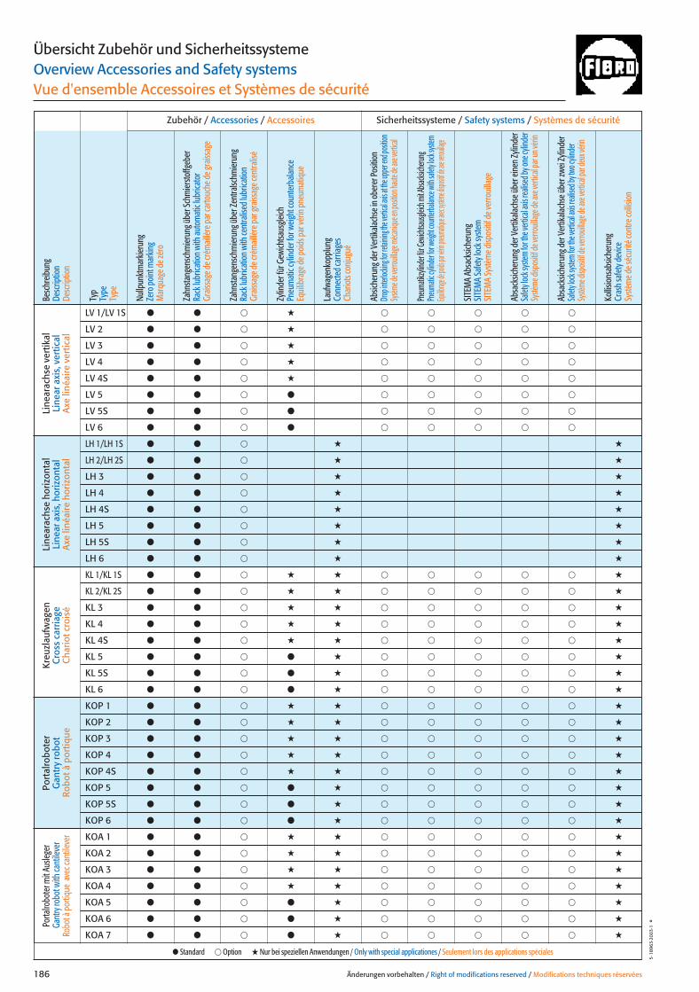
Zubehör / Accessories / Accessoires
Besc
hreib
ung
Desc
riptio
nDe
scrip
tion
Typ
Type
Type
Nullp
unkt
mar
kieru
ngZe
ro p
oint
mar
king
Mar
quag
e de z
éro
Zahn
stang
ensc
hmier
ung ü
ber S
chm
iersto
ffgeb
erRa
ck lu
brica
tion
with
auto
mat
ic lu
brica
tor
Grais
sage
de c
rém
aillèr
e par
carto
uche
de g
raiss
age
Zahn
stang
ensc
hmier
ung ü
ber Z
entra
lschm
ierun
gRa
ck lu
brica
tion
with
cent
ralis
ed lu
brica
tion
Grais
sage
de c
rém
aillèr
e par
grais
sage
cent
ralis
é
Zylin
der f
ür G
ewich
tsaus
gleich
Pneu
mat
ic cy
linde
r for
weig
ht co
unte
rbala
nce
Equi
libra
ge d
e poi
ds p
ar vé
rin p
neum
atiq
ue
Lauf
wage
nkop
plun
gCo
nnec
ted
carri
ages
Char
iots
conj
ugué
Absic
heru
ng d
er V
ertik
alach
se in
obe
rer P
ositi
onDr
op int
erlock
ing fo
r retai
ning th
e vert
ical ax
is at th
e upp
er en
d posi
tion
Sysèm
e de v
errou
illage
méca
nique
en po
sition
haute
de ax
e vert
ical
Pneu
matik
zylind
er für
Gewic
htsau
sgleic
h mit A
bsacks
icheru
ngPn
euma
tic cyl
inder
for we
ight co
unter
balan
ce wit
h safe
ty loc
k syst
emEqu
ilibrag
e de p
oids pa
r vérin
pneum
atique
avec sy
stème d
ispositif
de axe
veroui
llage
SITE
MA
Absa
cksic
heru
ngSI
TEM
A Sa
fety
lock
syste
mSI
TEM
A Sy
stèm
e disp
ositi
f de v
erro
uilla
ge
Absa
cksic
heru
ng d
er V
ertik
alach
se ü
ber e
inen
Zylin
der
Safet
y loc
k sys
tem fo
r the
verti
cal a
xis re
alise
d by o
ne cy
linde
rSy
stème
disp
ositif
de ve
rrouil
lage d
e axe
verti
cal p
ar un
vérin
Absa
cksic
heru
ng d
er V
ertik
alach
se ü
ber z
wei Z
ylind
erSa
fety l
ock s
ystem
for th
e vert
ical a
xis re
alised
by tw
o cyli
nder
Systè
me di
spos
itif de
verro
uillag
e de a
xe ve
rtical
par d
eux v
érin
Kollis
ions
absic
heru
ngCr
ash
safe
ty d
evice
Systè
me d
e séc
urité
cont
re co
llisio
n
Änderungen vorbehalten / Right of modifications reserved / Modifications techniques réservées186
5·18
963·
2003
·1°
Übersicht Zubehör und SicherheitssystemeOverview Accessories and Safety systemsVue d'ensemble Accessoires et Systèmes de sécurité
Sicherheitssysteme / Safety systems / Systèmes de sécurité
Line
arac
hse
vert
ikal
Line
ar a
xis,
ver
tical
Ax
e lin
éaire
ver
tical
Line
arac
hse
horiz
onta
lLi
near
axi
s, h
oriz
onta
lAx
e lin
éaire
hor
izon
tal
Kreu
zlau
fwag
enC
ross
car
riage
Cha
riot c
rois
é
Port
alro
bote
rG
antr
y ro
bot
Robo
t à p
ortiq
ue
Porta
lrobo
ter m
it Aus
leger
Gant
ry ro
bot w
ith ca
ntile
ver
Robo
t à p
ortiq
ue a
vec c
antil
ever
LV 1/LV 1S ● ● � � � � � � �
LV 2 ● ● � � � � � � �
LV 3 ● ● � � � � � � �
LV 4 ● ● � � � � � � �
LV 4S ● ● � � � � � � �
LV 5 ● ● � ● � � � � �
LV 5S ● ● � ● � � � � �
LV 6 ● ● � ● � � � � �
LH 1/LH 1S ● ● � � �
LH 2/LH 2S ● ● � � �
LH 3 ● ● � � �
LH 4 ● ● � � �
LH 4S ● ● � � �
LH 5 ● ● � � �
LH 5S ● ● � � �
LH 6 ● ● � � �
KL 1/KL 1S ● ● � � � � � � � � �
KL 2/KL 2S ● ● � � � � � � � � �
KL 3 ● ● � � � � � � � � �
KL 4 ● ● � � � � � � � � �
KL 4S ● ● � � � � � � � � �
KL 5 ● ● � ● � � � � � � �
KL 5S ● ● � ● � � � � � � �
KL 6 ● ● � ● � � � � � � �
KOP 1 ● ● � � � � � � � � �
KOP 2 ● ● � � � � � � � � �
KOP 3 ● ● � � � � � � � � �
KOP 4 ● ● � � � � � � � � �
KOP 4S ● ● � � � � � � � � �
KOP 5 ● ● � ● � � � � � � �
KOP 5S ● ● � ● � � � � � � �
KOP 6 ● ● � ● � � � � � � �
KOA 1 ● ● � � � � � � � � �
KOA 2 ● ● � � � � � � � � �
KOA 3 ● ● � � � � � � � � �
KOA 4 ● ● � � � � � � � � �
KOA 5 ● ● � ● � � � � � � �
KOA 6 ● ● � ● � � � � � � �
KOA 7 ● ● � ● � � � � � � �
● Standard � Option � Nur bei speziellen Anwendungen / Only with special applicationes / Seulement lors des applications spéciales
186 27.08.2004 9:08 Uhr Seite 2
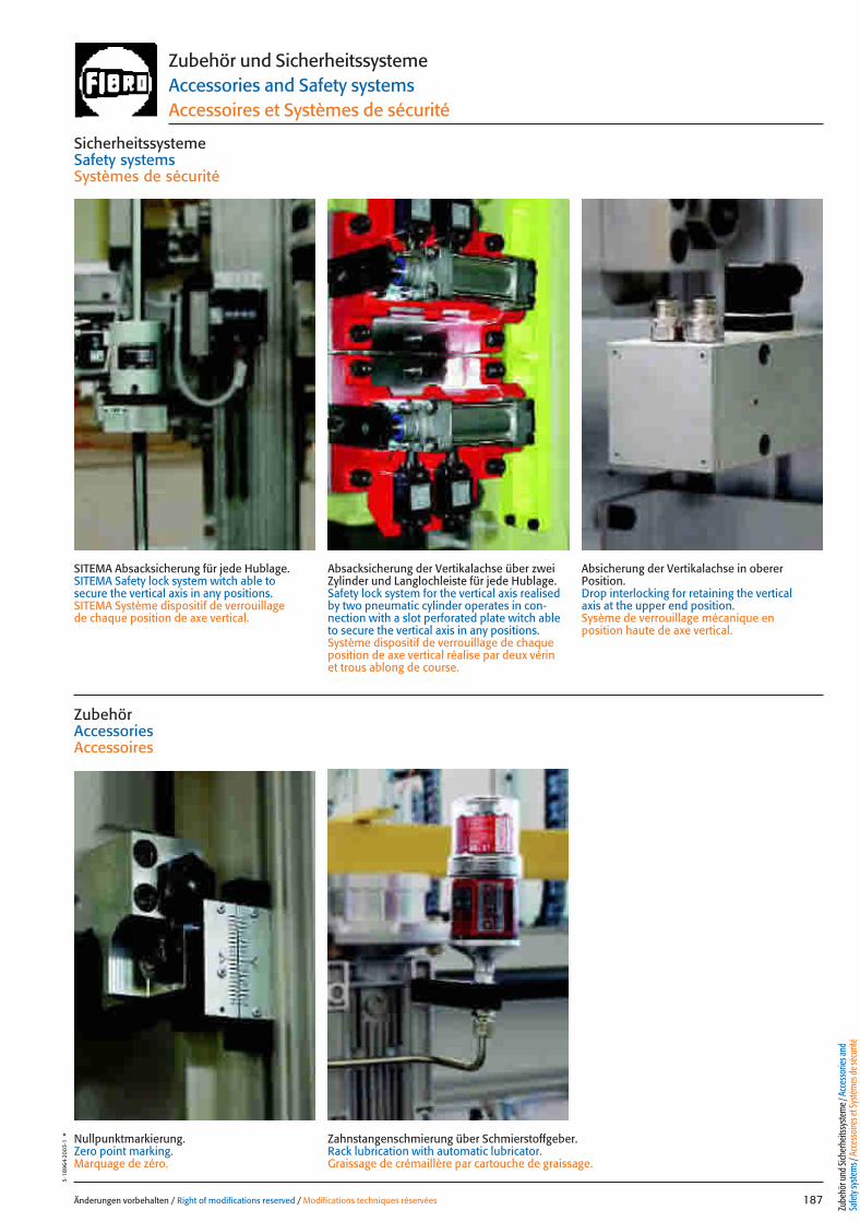
Änderungen vorbehalten / Right of modifications reserved / Modifications techniques réservées 187
5·18
964·
2003
·1°
SicherheitssystemeSafety systemsSystèmes de sécurité
ZubehörAccessoriesAccessoires
Zubehör und SicherheitssystemeAccessories and Safety systemsAccessoires et Systèmes de sécurité
SITEMA Absacksicherung für jede Hublage.SITEMA Safety lock system witch able to secure the vertical axis in any positions.SITEMA Système dispositif de verrouillage de chaque position de axe vertical.
Absacksicherung der Vertikalachse über zweiZylinder und Langlochleiste für jede Hublage.Safety lock system for the vertical axis realisedby two pneumatic cylinder operates in con-nection with a slot perforated plate witch ableto secure the vertical axis in any positions.Système dispositif de verrouillage de chaqueposition de axe vertical réalise par deux vérinet trous ablong de course.
Absicherung der Vertikalachse in oberer Position.Drop interlocking for retaining the vertical axis at the upper end position.Sysème de verrouillage mécanique en position haute de axe vertical.
Nullpunktmarkierung.Zero point marking.Marquage de zéro.
Zahnstangenschmierung über Schmierstoffgeber.Rack lubrication with automatic lubricator.Graissage de crémaillère par cartouche de graissage.
Zube
hör u
nd Si
cher
heits
syste
me /
Acc
esso
ries a
ndSa
fety
syste
ms/
Acc
esso
ires e
t Sys
tèm
es d
e séc
urité
187 27.08.2004 9:09 Uhr Seite 1
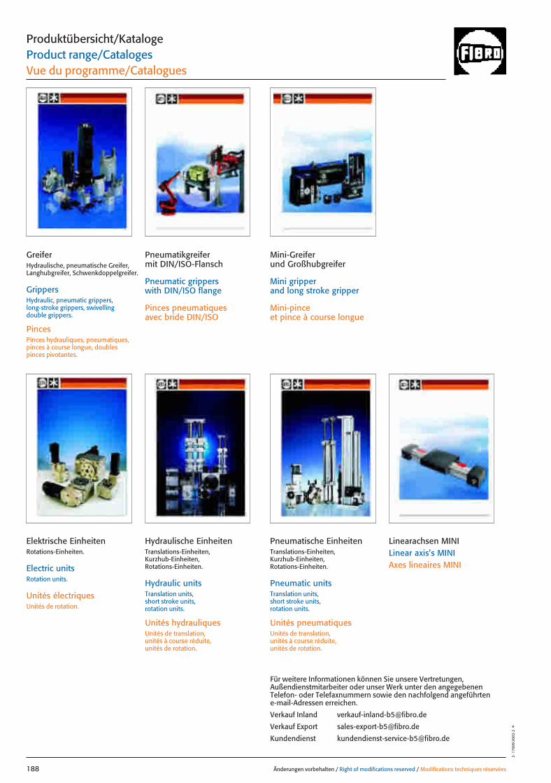
Änderungen vorbehalten / Right of modifications reserved / Modifications techniques réservées188
2·1
7909
·200
2·2
°
Produktübersicht/KatalogeProduct range/CatalogesVue du programme/Catalogues
GreiferHydraulische, pneumatische Greifer,Langhubgreifer, Schwenkdoppelgreifer.
GrippersHydraulic, pneumatic grippers, long-stroke grippers, swivelling double grippers.
PincesPinces hydrauliques, pneumatiques,pinces à course longue, doubles pinces pivotantes.
Pneumatikgreifermit DIN/ISO-Flansch
Pneumatic gripperswith DIN/ISO flange
Pinces pneumatiquesavec bride DIN/ISO
Pneumatische EinheitenTranslations-Einheiten, Kurzhub-Einheiten, Rotations-Einheiten.
Pneumatic unitsTranslation units, short stroke units, rotation units.
Unités pneumatiquesUnités de translation, unités à course réduite, unités de rotation.
Mini-Greiferund Großhubgreifer
Mini gripperand long stroke gripper
Mini-pinceet pince à course longue
Für weitere Informationen können Sie unsere Vertretungen,Außendienstmitarbeiter oder unser Werk unter den angegebenenTelefon- oder Telefaxnummern sowie den nachfolgend angeführtene-mail-Adressen erreichen.
Verkauf Inland [email protected]
Verkauf Export [email protected]
Kundendienst [email protected]
Hydraulische EinheitenTranslations-Einheiten, Kurzhub-Einheiten, Rotations-Einheiten.
Hydraulic unitsTranslation units, short stroke units, rotation units.
Unités hydrauliquesUnités de translation, unités à course réduite, unités de rotation.
Elektrische EinheitenRotations-Einheiten.
Electric unitsRotation units.
Unités électriquesUnités de rotation.
Linearachsen MINILinear axis’s MINIAxes lineaires MINI
188 27.08.2004 9:09 Uhr Seite 2
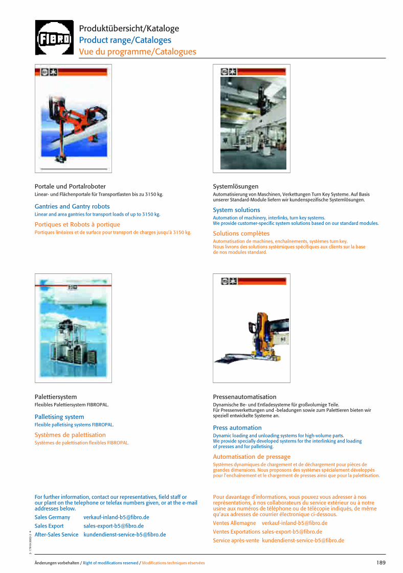
Änderungen vorbehalten / Right of modifications reserved / Modifications techniques réservées 189
2·1
7910
·200
2·2
°Produktübersicht/KatalogeProduct range/CatalogesVue du programme/Catalogues
Pour davantage d’informations, vous pouvez vous adresser à nosreprésentations, à nos collaborateurs du service extérieur ou à notreusine aux numéros de téléphone ou de télécopie indiqués, de mêmequ’aux adresses de courrier électronique ci-dessous.
Ventes Allemagne [email protected]
Ventes Exportations [email protected]
Service après-vente [email protected]
For further information, contact our representatives, field staff orour plant on the telephone or telefax numbers given, or at the e-mailaddresses below.
Sales Germany [email protected]
Sales Export [email protected]
After-Sales Service [email protected]
Portale und PortalroboterLinear- und Flächenportale für Transportlasten bis zu 3150 kg.
Gantries and Gantry robotsLinear and area gantries for transport loads of up to 3150 kg.
Portiques et Robots à portiquePortiques linéaires et de surface pour transport de charges jusqu’à 3150 kg.
PressenautomatisationDynamische Be- und Entladesysteme für großvolumige Teile.Für Pressenverkettungen und -beladungen sowie zum Palettieren bieten wir speziell entwickelte Systeme an.
Press automationDynamic loading and unloading systems for high-volume parts. We provide specially developed systems for the interlinking and loading of presses and for palletising.
Automatisation de pressageSystèmes dynamiques de chargement et de déchargement pour pièces de grandes dimensions. Nous proposons des systèmes spécialement développéspour l’enchaînement et le chargement de presses ainsi que pour la palettisation.
PalettiersystemFlexibles Palettiersystem FIBROPAL.
Palletising systemFlexible palletising systems FIBROPAL.
Systèmes de palettisationSystèmes de palettisation flexibles FIBROPAL.
SystemlösungenAutomatisierung von Maschinen, Verkettungen Turn Key Systeme. Auf Basis unserer Standard-Module liefern wir kundenspezifische Systemlösungen.
System solutionsAutomation of machinery, interlinks, turn key systems. We provide customer-specific system solutions based on our standard modules.
Solutions complètesAutomatisation de machines, enchaînements, systèmes turn key.Nous livrons des solutions systémiques spécifiques aux clients sur la base de nos modules standard.
189 27.08.2004 9:10 Uhr Seite 1

DE
123 Heinrich Siggel GmbHWaldstraße 1 · 14163 Berlin
14000 Tel. 030-802 90 13 · Fax 030-802 90 [email protected]
123 Walter Ruff GmbHPostfach 110266 · 28082 Bremen
28000 Heerenholz 9 · 28307 BremenTel. 0421-438 78-0 · Fax 0421-438 [email protected] · www.praeziruff.de
�23 Außendienst Karl-Heinz Keßler30000 Mehlstraße 8 · 33729 Bielefeld33000 Tel. 0521-764 43 · Fax 0521-770 75 58
Mobil-Tel. 0170-564 34 [email protected]
1�� Walter Ruff GmbH PräzisionswerkzeugeBerliner Straße 28 · 31174 Schellerten
31000 Tel. 05123-20 40 · Fax 05123-26 40
1�� Oltrogge & Co.Postfach 102093 · 33520 Bielefeld
33000 Finkenstraße 61 · 33609 BielefeldTel. 0521-32 08-0 · Fax 0521-32 [email protected] · www.oltrogge.de
1�� Schwab GmbHPostfach 1209 · 35323 Mücke
35000 Bergwiesenstraße 10 · 35325 MückeTel. 06400-80 11 · Fax 06400-80 12
�23 Ing. Büro für Automation Dirk Ahke VDIZum Wenzelnberg 2a · 40764 Langenfeld
40000 Tel. 02173-270 41-0 · Fax 02173-270 [email protected]
1�� Außendienst Lars JahnckeFlockertsberg 17 · 42653 Solingen
40000 Tel. 0212-254 34 62 · Fax 0212-254 33 9050000 Mobil-Te. 0170-763 71 25
1�� Außendienst Hartwig HennemannStaubenthaler Höhe 79
40000 42369 Wuppertal50000 Tel. + Fax 0202-759 55 80
Mobil-Tel. 0175-296 59 [email protected]
1�� Normalien-Zentrale-Siegerland Bernd KreitzbergPostfach 1132 · 57225 Wilnsdorf
57000 Rudersdorfer Straße 18 · 57234 WilnsdorfTel. 02739-25 44 · Fax 02739-41 16Mobil-Tel. 0170-274 27 95
1�� Stahlschmidt Industriebedarf und -vertretungenPostfach 65 · 58846 Herscheid
58000 Eichenweg 12 · 58849 HerscheidTel. 02357-30 99 · Fax 02357-22 55Mobil-Tel. 0171-642 57 97e.stahlschmidt@t-online.dewww.stahlschmidt-industrievertretung.de
1�� Außendienst Volker HottesErzberger Straße 1 · 64846 Groß-Zimmern
64000 Tel. 06071-416 10 · Fax 06071-416 10Mobil-Tel. 0171-957 79 [email protected]
�23 Außendienst Guido SteinbrückGartenfeldstraße 28 · 65396 Walluf
65000 Tel. 06123-70 46 90 · Fax 06123-70 46 91Mobil-Tel. 0171-229 45 [email protected]
�23 Außendienst Henning ReinerAm Eselsberg 53 · 89075 Ulm
71000 Tel. 0731-95 08 05 44 · Fax 0731-95 08 05 45Mobil-Tel. 0151-11 71 29 [email protected]
�23 Außendienst Peter FinkenbeinerGrüner Weg 2 · 72218 Wildberg
72000 Tel. 07054-83 07 · Fax 07054-92 89 59Mobil-Tel. 0170-564 31 [email protected]
1�� Außendienst Matthias EhrenfriedBreisgaustraße 9 · 74172 Neckarsulm
74000 Tel. 07132-98 94 82 · Fax 07132-98 94 82Mobil-Tel. 0171-864 95 [email protected]
1�� Außendienst Manfred WagnerBreslauer Straße 57 · 74372 Sersheim
74000 Tel. 07042-350 86 · Fax 07042-350 86Mobil-Tel. 0170-563 52 [email protected]
1�� Nestle & Koch · Stahllager GmbHMaximilianstraße 159 · 75172 Pforzheim
75000 Tel. 07231-457 67-0 · Fax 07231-457 67 [email protected]
1�� Außendienst Wilhelm VolkRintheimer Hauptstraße 135 · 76131 Karlsruhe
76000 Tel. 0721-61 20 95 · Fax 0721-61 20 95Mobil-Tel. 0170-850 56 86
1�� Hamacher GmbHPostfach 3308 · 78022 VS-Schwenningen
78000 Grabenäckerstraße 47 · 78054 VS-SchwenningenTel. 07720-349 69 · Fax 07720-341 [email protected]
123 Jugard & Künstner GmbHLandsberger Straße 289/l · 80687 München
80000 Tel. 089-546 15 60 · Fax 089-580 27 [email protected]
123 Jugard & Künstner GmbHPostfach 900152 · 90492 Nürnberg
90000 Thomas-Mann-Straße 63 · 90471 NürnbergTel. 0911-86 08 11 · Fax 0911-86 08 [email protected]
1�� HELD WerkzeugmaschinenPräzisionswerkzeuge GmbH
07500 Tivolistraße 1 · 07545 GeraTel. 0365-824 91-0 · Fax 0365-824 91 11e-mail: [email protected] · www.held-wzm.de
�23 Außendienst Stefan SchumannForstweg 44 · 07570 Weida
07500 Tel. 036603-408 02 · Fax 036603-602 37Mobil-Tel. 0170-564 51 [email protected]
AT
123 Rath & Co. Ges. m.b.H.Teiritzstrasse 3 · 2100 KorneuburgTel. +43 2262-608 · Fax +43 [email protected] · www.rath-co.at
AU
1�� Bruderer Presses Australia Pty. Ltd.92 Trafalgar Street · Annandale, NSW 2038Tel. +61-419-400-995 · Fax [email protected]
�23 Enmor Tool & Machine Co. Pty. Ltd.Unit 18 · 41 Walter StreetP.O. Box 39 · Belmont, NSW 2280Tel. +61-249-455-898 · Fax [email protected]
BA
123 Oro-Tech trgovina d.o.o.Ulica borcev 1/b · SI-2000 MariborTel. +386 2-426 08 43 · Fax +386 2-426 08 [email protected]
BE
�23 Doedijns Fluitronics NV/SAZoning d’Amay Allée II n° 4 · 4540 AmayTel. +32 8 551 9696 · Fax +32 8 551 9697
1�� Schiltz S.A.Chaussee de Gand 1034 · 1082 BruxellesTel. +32 2 464 4830 · Fax +32 2 464 [email protected]
BG
1�� Bavaria 2002 EOODPirotstr. 22 · 5100 Gorna OrjachovizaTel. +359 618 64158 · Fax +359 618 [email protected]
BR
�2� Coloman Industria e Comerciode Maquinas e Ferramentas Ltda.Rua A-N° 315 · Parque Industrial · Caixa Postal 49Franco da Rocha - SP · CEP - 07851-970Tel. +55-11-4449-4460 · Fax [email protected]
1�� LCPA Ltda.Rua Maria Maiolino de Souza, 40/Sala 04CEP 13.230-270 São Paulo, SPTel. +55-11-4038-4677 · Fax [email protected]
CH
�23 FIBRO GmbH ZweigniederlassungBuechstrasse 10 · 5027 HerznachTel. +41 62-878 18 80 · Fax +41 62-878 18 [email protected] · www.fibro.com
1�� Brütsch/Rüegger AGIn der Luberzen 1 · 8902 UrdorfTel. +41-1 736 63 63 · Fax +41-1 736 63 [email protected] · www.b-r.ch
CL
1�� Bermat S.A.Coyancura 2283, Of. 601 · Casilla 9781 · SantiagoTel. +56-2-231 88 77 · Fax +56-2-231 42 [email protected] · www.bermat.cl
CN
123 Forsteppe Precision Engineering Co. Ltd.199-3 LuXing Road · Liuzao TownNanhui County · 201322 ShanghaiTel. +86 21-68 16 01 69 · Fax +86 21-68 16 01 [email protected]
123 Forsteppe Trading (Guangzhou)Room E, 11/F. · East Tower Tianxing BuildingNo. 21, Zhongshan First Road · 510600 GuangzhouTel. +86 20-87 32 91 29 · Fax +86 20-87 32 82 [email protected]
CY
1�� Militos Trading Ltd.K. Erotokritou & A. Demetriou Ltd.P.O.B. 27297 · 1643 NicosiaTel. +357 2-75 12 56 · Fax +357 2-75 22 [email protected]
CZ
1�3 Gore s.r.o.Prístavní 6 · CZ-63500 Brno-BystrcTel. +420 5-41 59 25 18 · Fax +420 5-41 59 25 [email protected] · www.gore.cz
�2� SK Technik, spol. s r.o.Merhautova 20 · 61300 BrnoTel. +42 0 5-45 42 95 11 · Fax +42 0 5-45 21 12 [email protected] · www.sktechnik.cz
DK
1�� A/S Erling B. IbsenMetalbuen 28 · Postbox 79 · 2750 BallerupTel. +45 44-97 81 11 · Fax +45 44-68 06 [email protected] · www.ebi.dk
�2� BONDY A/SIndustriparken 16-18 · 2750 BallerupTel. +45 7015 1414 · Fax +45 4464 1416
��3 PMC Technology A/SKlausdalsbrovej 1 · 2860 SøborgTel. +45 7021 2121 · Fax +45 7021 [email protected] · www.pmctechnology.dk
DZ
1�� Pneumacoupe Blida Boufarik86 Bld. Menad Mohamed · Boufarik, 09400 BlidaTel. +213 3-47 56 55 · Fax +213 3-47 56 [email protected]
EE
1�� Cle Baltik OueLaki 9A · 10621 TallinTel. +372 509 3228 · Fax +372 650 [email protected]
EG
1�� Smeco68, Abdel Rahman El Raffei St.11351-Heliopolis West, CairoTel. +20 2-620 06 71 · Fax +20 2-620 06 [email protected]
ES
123 Daunert Máquinas-Herramientas, S.A.C/. Tirso de Molina s/n Esqina C/. Albert EinsteinPolígono Industrial Almeda08940 Cornellá de Llobregat · BarcelonaTel. +34 93-475 14 80 · Fax +34 93-377 64 [email protected] · www.daunert.com
FI
123 OY Christer Lindholm Eng. ABSantalantie 25, PL. 66 · 10901 HankoTel. +358 19-280 72 00 · Fax +358 19-248 43 [email protected] · www.clegroup.fi
NormalienStandard PartsEléments normalisés
RundschalttischeIndexing TablesPlateaux diviseurs
Automation+RobotikAutomation+RoboticsAutomatisme+robotique
VertretungenRepresentativesReprésentations
1
2
3
0 · 1
7783
· 08
/200
4 · 2
4 �
PostleitzahlgebietZip CodeCode postal
998Vertreter_D_E_F 30.08.2004 12:24 Uhr Seite 2
FR
123 FIBRO19/21, rue Jean Lolive · 93170 BagnoletB.P. no 129 · 93172 Bagnolet CedexTél. +33 1-43-62-18-80 · Fax +33 [email protected] · www.fibro.fr
Secteur Franche Comté1�� Codimec SA
Rue des Maurapans · ZAC de ValentinBP no. 3051 · 25046 Bésançon CedexTel. +33 3-81-88-83-11 · Fax +33 3-81-88-05-45
GB
1�� Burrhart Machinery Ltd.Cradock Road · Luton · Beds LU4 0JFTel. +44 1582-56 3400 · Fax +44 1582-49 39 [email protected] · www.burrhart.co.uk
�23 W. & H. Eves Ltd.PO Box 6544 · Burton on Trent DE13 7ZXTel. +44 1543-47 34 44 · Fax +44 1543-47 21 [email protected]
GR
1�� Mek-Maria Koutseris & Co.Pyloy 100 · 10441 AthenTel. +30 210-522 05 57 · Fax +30 210-522 12 [email protected] · www.mek.com.gr
HK
123 Forsteppe Enterprise Ltd.Unit 207, 2/F · Shing Chuen Industrial Building25-27 Shing Wan RoadTai Wai Shatin N.T. (Hong Kong)Tel. +852-26 01 13 68 · Fax +852-26 01 16 [email protected]
HR
123 Oro-Tech trgovina d.o.o.Ulica borcev 1/b · SI-2000 MariborTel. +386 2 426 08 43 · Fax +386 2 426 08 [email protected]
HU
1�� Rath & Co. Ges. m.b.H.Teiritzstraße 3 · AT-2100 KorneuburgTel. +43 2 262-608 · Fax +43 2 [email protected] · www.rath-co.at
ID
1�� Pt. Normalindo Tunas SentosaJintanjung Duren Raya 21 A · Jakarta 11470Tel. +62 21-564 07 18 · Fax +62 21-564 07 [email protected]
IE
1�� K & A Engineering Ltd.49 Barrack Street · Waterford CityTel. +353 51-37 82 55 · Fax +353 51-37 90 [email protected]
IL
123 A. J. Englander 1980 Ltd.13 Harechev Street · Tel Aviv 67771Tel. +972 3-537 36 36 · Fax +972 3-537 33 [email protected] · www.englander.co.il
IN
1�� Nitoo Sales · Antaral Plot No 464/B/2Dhotre Marg. Ghaneshkhind Road · Pune - 411016Tel. +91 20-25 65 62 39 · Fax +91 20-25 65 64 [email protected] · www.nitoo.com
�23 NN Combined Engineering Agencies Private Ltd.Dr. Ranji Block, First Floor125. M. G. Road · Secunderabad 500003 A.P.Tel. +91 40-27 84 42 79 · Fax +91 40-27 84 16 [email protected] · www.nncea.com
IR
123 Eximrad Co.268 Dr. Mofatah Ave. · Tehran 15848Tel. +98 21-882 12 03 · Fax +98 21-830 97 [email protected]
IT
1�� Millutensil S.R.L.Corso Buenos Aires, 92 · 20124 MilanoTel. +39 2-29 40 43 90 · Fax +39 2-204 66 [email protected] · www.millutensil.com
IT
�23 NC Componenti S.R.L.Via F. Raimondo, 11/B · 10090 Cascine Vica-Rivoli (TO)Tel. +39 11-957 52 22 · Fax +39 11-957 51 [email protected] · www.nccomponenti.it
JP
�2� Tomita Co. Ltd.No. 1-18-16 · 1-Chome Ohmorinaka Ohta-Ku · TokioTel. +81 3-37 65 49 11 · Fax +81 3-37 67 83 [email protected]
KR
1�� Jinsan Commercial Co. Ltd.Rm 103, 12 Dong, Anyang Int‘L · Circulation Complex#555-9, Hogye-Dong, Dongan-GuTel. +82 31 479 31 81 · Fax +82 31 479 31 [email protected]
�2� Jinsung Trading Corp.Dong Woo Bld. 303#520-2, 2AV Choryang Dong Gu, PusanTel. +82 51-466-5462/3 · Fax +82 [email protected]
��3 Intech Automation Inc.13 FL. Jeil Bd., 94-46, Youngdeungpo7-Ga, Youngdeungpo-ku · Seoul 150-037Tel. 02-26 32 67 70 · Fax 02-26 32 68 [email protected]
MY
123 FIBRO Asia Pte. Ltd.121, Genting Lane, 2nd Floor · Singapore 349572Tel. +65 68 46 33 03 · Fax +65 68 46 33 [email protected] · www.fibro.com
NL
�23 Item Systems B.V.Zwarte Zee 40-42 · 3144 DE MaassluisTel. +31 10-593 72 60 · Fax +31 10-592 85 [email protected] · www.item-international.com
1�� Jeveka B.V.Postbus 22966 · Keienbergweg 81100 DL-Amsterdam · 1101 GB AmsterdamTel. +31 20-342 03 42 · Fax +31 20-342 03 [email protected] · www.jeveka.com
NO
�2� Kaspo Maskin ASHoeggveien 66 · 7489 TrondheimTel. +47 73 96 96 00 · Fax +47 73 96 96 [email protected] · www.kaspo.no
1�� Wolf VerktoyPostboks 602, Busterud · 1754 HaldenTel. +47 69 17 89 19 · Fax +47 69 17 89 45
PE
1�� Ing. E. Brammertz S.c.r.l.Av. José Pardo 182 · OF. 905Apartado 0173 · Miraflores, Lima 18Tel. +51 1 445 81 78 · Fax +51 1 445 19 [email protected]
PL
1�� Laska Technika Przemyslowa Sp.z.o.o.ul. Budowlanych 43 · 43-100 TychyTel. +48 32-326 24 50 · Fax +48 32-326 24 [email protected] · www.laska.com.pl
PT
1�� Ferrometal Lda.Estrada Manuel Correia LopesRua da Rosita, Lote 12 · Conceição da Abóboda2785-543 S. Domingos de Rana-CascaisTel. +35 21-444 71 60 · Fax +35 21-444 71 [email protected]
�2� Seri Lda.Zona Industrial da VarzielaAv. José Ramos Maia – Lote no 3, Apartado 1974481-911 Vila do CondeTel. +35 252 24 85 40 · Fax +35 252 24 85 [email protected]
RO
1�� Proiect Alide SrlStr. Plaiul Muntelui 22 · Sect. 1 BucarestiTel. +40 21-305 59 54 · Fax +40 21-222 07 [email protected]
SA
1�� Abdullah Yahya Munshi EstP. O. Box 20123 · 21455 JeddahTel. +966 2-643 62 42 · Fax +966 2-643 62 [email protected]
SE
�23 Dankab Verktygsmaskiner ABBox 4002 · 18104 LidingöLarsbergsvägen 12b · 18139 LidingöTel. +46 854 44 03 40 · Fax +46 854 44 03 [email protected] · www.dankab.se
1�� Lideco ABVerkstadsvägen 4 · 51463 DalstorpTel. +46 321 53 03 50 · Fax +46 321 603 [email protected] · www.lideco.se
SG
123 FIBRO Asia Pte. Ltd.121, Genting Lane, 2nd Floor · Singapore 349572Tel. +65 68 46 33 03 · Fax +65 68 46 33 [email protected] · www.fibro.com
SI
123 Oro-Tech trgovina d.o.o.Ulica borcev 1/b · SI-2000 MariborTel. +386 2 426 08 43 · Fax +386 2 426 08 [email protected]
SK
1�3 Gore s.r.o.Prístavní 6 · CZ-63500 Brno-BystrcTel. +420 5-41 59 25 18 · Fax +420 5-41 59 25 [email protected] · www.gore.cz
�2� SK Technik, spol. s.r.o.Merhautova 20 · 61300 BrnoTel. +420 5-45 21 16 66 · Fax +420 5-45 21 12 [email protected] · www.sktechnik.cz
TR
1�� Ender Kesici Ve Teknik · Takimlar Ltd. Sti.Tersane Caddesi No. 16 · 80000 Karaköy/IstanbulTel. +90 212-253 26 00 · Fax +90 212-254 57 [email protected] · www.enderltd.com
�23 Fikret Erdogan ve Ort. Koll. Sti.Otakçilar Cad. No. 56 · 34050 Eyüp-IstanbulTel. +90 212-544 87 53 · Fax +90 212-567 99 [email protected]
TW
1�� SunNan Enterprises Co. Ltd.2F, No. 7, Alley 6, Lane 235 · Pao-Chiao RoadHsin-Tien City · TaipeiTel. +886 2-29 17 6454 · Fax +886 2-29 11 03 [email protected]
US
123 FIBRO Inc.139 Harrison Ave. · Rockford, IL 61104P. O. B. 5924 · Rockford, IL 61125Tel. +1 815-229 13 00 · Fax +1 815-229 13 [email protected] · www.fibro.com
YU
1�� Andrija Tesic, Dipl. Ing.Partisanska 12/a-II · 11090 BeogradTel. +381 11-533 83 62 · Fax +381 11-533 83 [email protected]
ZA
123 Herrmann & Herrmann Pty. Ltd.24, Shaft Road · P. O. B. 13030 · Knights 1413Tel. +27 11 828 01 00 · Fax +27 11 828 60 [email protected] · www.hermstools.com
FIBROGmbH
1 Normalien · Standard Parts · Eléments normalisésPostfach 1120 · D-74851 HassmersheimAugust-Läpple-Weg · D-74855 HassmersheimTel. (+49)6266-73-0*· Fax (+49)6266-73-237
2 Rundschalttische · Indexing Tables · Plateaux diviseursPostfach 1120 · D-74183 WeinsbergWeidachstrasse 41-43 · D-74189 WeinsbergTel. (+49)7134-73-0*· Fax (+49)7134-73-120
3 Automation+Robotik · Automation+Robotics · Automatisme+robotiquePostfach 1120 · D-74851 HassmersheimAugust-Läpple-Weg · D-74855 HassmersheimTel. (+49)6266-73-0*· Fax (+49)6266-73-213
0 · 1
7783
· 08
/200
4 · 2
4 �
998Vertreter_D_E_F 30.08.2004 12:26 Uhr Seite 3
0·1
7927
·05/
2004
·10
�
FIBRO GmbH
1 NormalienStandard PartsEléments normalisés
Postfach 1120DE-74851 HassmersheimAugust-Läpple-WegDE-74855 HassmersheimTelefon +49 (0) 6266 - 73 - 0*Telefax +49 (0) 6266 - 73 - 237e-mail: [email protected]://www.fibro.com
2 RundschalttischeIndexing TablesPlateaux diviseurs
Postfach 1120DE-74183 WeinsbergWeidachstrasse 41– 43DE-74189 WeinsbergTelefon +49 (0) 7134 - 73 - 0*Telefax +49 (0) 7134 - 73 - 120e-mail: [email protected]://www.fibro.com
3 Automation+RobotikAutomation+RoboticsAutomatisme+robotique
Postfach 1120DE-74851 HassmersheimAugust-Läpple-WegDE-74855 HassmersheimTelefon +49 (0) 6266 - 73 - 0*Telefax +49 (0) 6266 - 73 - 213e-mail: [email protected]://www.fibro.com
1 2 3US
1
FIBRO Inc.
P. O. Box 5924US-Rockford, IL 61125139 Harrison AvenueUS-Rockford, IL 61104Phone +1 815 - 2291300Fax +1 815 - 2291303e-mail: [email protected]://www.fibro.com
FIBROBP no 129FR-93172 Bagnolet Cedex19/21, rue Jean LoliveFR-93170 BagnoletTéléphone +33(0)143621881Télécopieur +33(0)148591747e-mail: [email protected]://www.fibro.fr
FR
SG
1 2 3FIBRO ASIA Pte.Ltd.
121 Genting Lane2nd floorSG-Singapore 349572
Phone + 65 - 68 46 3303Fax + 65 - 68 46 3302e-mail: [email protected]://www.fibro.com
2 3FIBROBP no 129FR-93172 Bagnolet Cedex19/21, rue Jean LoliveFR-93170 BagnoletTéléphone +33 (0)143621889Télécopieur +33 (0)148187346e-mail: [email protected]://www.fibro.fr
FR
2 3FIBRO GmbH Zweigniederlassung
Buechstrasse 10CH-5027 HerznachTelefon +41 (0) 62-87818 80Telefax +41 (0) 62-87818 82e-mail: [email protected]://www.fibro.com
CH
000_U1ohneRuecken 06.09.2004 11:28 Uhr Seite 2