avery dennison alx924 labelprinter parameters
DESCRIPTION
Avery Dennison ALX924 Labelprinter parametersTRANSCRIPT

09/09 Rev. 5.03-01 USER- / SERVICE MANUAL
64-xx – DPM – PEM – ALX 92x – PM 3000
Info Printouts & ParametersGeneral Information ...................................... 6
Important setting instructions .................... 6Area of application .................................... 6
Operating the parameter menu ..................... 8Example .................................................... 8Parameter Menu 64-xx .............................. 9Parameter Menu DPM / PEM / ALX 92x/PM 3000 .................................................. 10
Overview Parameter Menus ....................... 11Understanding the Parameter Overviews 1164-xx Parameter ...................................... 12DPM / PEM / ALX 92x Parameter ............. 15PM 3000 .................................................. 18
Alphabetical Parameter List ........................ 21
PRINT INFOPrinter status ........................................... 24Memory status ......................................... 26Font status .............................................. 27Flashdata status...................................... 30Service Status ......................................... 31Dottest endless ....................................... 32Dottest punched ...................................... 32Reference label ....................................... 33RFID Status............................................. 34
PRINT PARAMETERSPrint speed .............................................. 35Feed speed ............................................ 35Material type............................................ 36Material length......................................... 36Material width .......................................... 36Print direction .......................................... 37Punch offset ............................................ 38Bar code multip. ...................................... 39Tradit. Imaging ....................................... 40UPC plain-copy ....................................... 40EAN Readline.......................................... 40EAN sep. lines......................................... 41Rotated Barcodes ................................... 41Dispense Mode ....................................... 41Dispenseposition..................................... 44
Cut mode ................................................. 46Cut speed ................................................ 48Cut position.............................................. 48Double cut................................................ 48Rewind direction ......................................49X - Printadjust .......................................... 49Y – Printadjust ......................................... 49Punch mode............................................. 50Punch level .............................................. 50
INTERFACE PARA> EASYPLUGINTERPRInterface................................................... 51Spooler mode .......................................... 51Printer ID No. ........................................... 52Spooler size ............................................. 52Offline mode ............................................ 52Interface delay ......................................... 52
> COM1 PORTBaud rate ................................................. 53No. of data bits......................................... 53Parity........................................................ 53Stop bits................................................... 53Data synch............................................... 54Frame error.............................................. 54
> COM2 PORTBaud rate ................................................. 54No. of data bits......................................... 54Parity........................................................ 54Stop bits................................................... 55Data synch............................................... 55Serial Port Mode...................................... 55Frame error.............................................. 55
> COM4 PORTBaud rate ................................................. 56No. of data bits......................................... 56Parity........................................................ 56Stop bits................................................... 56Data synch............................................... 56Frame error.............................................. 56

09/09 Rev. 5.03-01 USER- / SERVICE MANUAL
64-xx – DPM – PEM – ALX 92x – PM 3000
> CENTRONICSPnP function............................................ 57
> NETWORK PARAM.IP addressassign..................................... 57IP address ............................................... 57Net mask ................................................. 57Gateway address .................................... 58Port address............................................ 58Ethernet speed........................................ 58MAC address .......................................... 58SNMP agent............................................ 58SNMP password ..................................... 58FTP server .............................................. 59FTP password ......................................... 59WEB server ............................................. 60WEB display refr ..................................... 61WEB admin passw. ................................. 61WEB supervisor p. .................................. 61Time client............................................... 62Time server IP......................................... 62Sync. Interval .......................................... 62DHCP host name .................................... 63WLAN SSID ............................................ 63WLAN WEP............................................. 63WLAN default key ................................... 64WLAN 64Bit key 1 ................................... 64WLAN 64Bit key 2 ................................... 64WLAN 64Bit key 3 ................................... 64WLAN 64Bit key 4 ................................... 64WLAN 128Bit key 1 ................................. 65WLAN 128Bit key 2 ................................. 65WLAN 128Bit key 3 ................................. 65WLAN 128Bit key 4 ................................. 65WLAN com quality................................... 65WLAN signal lev...................................... 66
> OPTIONSRemote Display....................................... 66OLV Option ............................................. 66RFID Option ............................................ 67StandAlone Input..................................... 67
> DRIVEASSIGNMENTDrive C .................................................... 68
Drive D..................................................... 68Drive E..................................................... 68Drive F ..................................................... 69Drive G..................................................... 69
SYSTEM PARAMETERSHead disp dist. ......................................... 70Speed unit ............................................... 70Cover open error...................................... 70Foil end warning ...................................... 71Foil warn stop .......................................... 71Display mode........................................... 71Dispense counter..................................... 72Autom. dot check..................................... 73Early dottest............................................. 73Latest dottest ........................................... 74Dottestarea from...................................... 75Dottestarea to .......................................... 75Print Interpret. .......................................... 76Character sets ......................................... 77Character filter ......................................... 78Light sens. type........................................ 78Head-sensor dist...................................... 78Sens. punch-LS ....................................... 79Ribbon autoecon...................................... 79Ribbon economy limit .............................. 79Feed mode............................................... 80Turn-on mode .......................................... 80Error reprint.............................................. 80EasyPlug error ......................................... 80Single job mode....................................... 81Head resistance....................................... 81Temp. reduction....................................... 82Voltage offset........................................... 82Expand Logo ........................................... 82Miss. label tol. .......................................... 83Gap detect mode ..................................... 83Foil stretching ..........................................84Max InitFeedback .................................... 84Mat.end detect. ........................................ 84Periph. device.......................................... 85Singlestartquant....................................... 85External signal ......................................... 85
09/09 Rev. 5.03-01 USER- / SERVICE MANUAL
64-xx – DPM – PEM – ALX 92x – PM 3000
Dispensing mode .................................... 86Application mode..................................... 86Start mode............................................... 87Start source............................................. 87Dispensing edge ..................................... 88Head disp dist ......................................... 88Transport mode....................................... 88Signal edge ............................................. 89Apply key................................................. 89Print contrast ........................................... 89Ram disk size.......................................... 90Font downl. area ..................................... 90Free store size ........................................ 91Print info mode ........................................ 91Reprint function ....................................... 91Language ................................................ 92Keyboard................................................. 92Signal / buzzer ........................................ 92Access authoriz. ...................................... 92Realtime clock......................................... 94Material feed ........................................... 94
APPLICATOR PARAApplicator type ........................................ 95Application mode..................................... 96Start print mode....................................... 96Start error stop ........................................ 97APSF sensor res. .................................... 97Startdelay ................................................ 97Dwell time................................................ 97Blow on time............................................ 98Restart delay ........................................... 98Position timeout....................................... 98
I/O BOARDStart delay ............................................... 99Start print mode....................................... 99Reprint Signal........................................ 100Feed input ............................................. 100Pause input ........................................... 100Error output ........................................... 101Error Polarity ......................................... 101Status output ......................................... 102
Status polarity ........................................ 102End print mode ...................................... 102
OLV PARAMETERSVerify mode............................................ 103Ref Decode............................................ 103Decodability ........................................... 103Modulation ............................................. 103Defects................................................... 104Edge contrast......................................... 104Rmin/Rmax............................................ 104Symbol contrast ..................................... 104PCS ....................................................... 104R (white) ................................................ 105R (black) ................................................ 105Ratio ...................................................... 105ANSI symbol grade................................ 105Dist. head-beam .................................... 106Cancel. printing...................................... 106Reprint quantity...................................... 106Verify mode............................................ 106
DP INTERFACEInterface type......................................... 107Start delay.............................................. 107Start print mode ..................................... 108End print mode ...................................... 108Reprint signal......................................... 109Ribbon signal ......................................... 109Material signal........................................ 109Mat. signal stop...................................... 110Feed input.............................................. 110Pause input............................................ 110Start error stop....................................... 111Internal inputs ........................................ 111Apply mode ............................................112
MLI PARAMETERSVersion................................................... 113Darkness................................................ 113Control Prefix ......................................... 113Format Prefix ......................................... 114Delimiter Char........................................ 114
09/09 Rev. 5.03-01 USER- / SERVICE MANUAL
64-xx – DPM – PEM – ALX 92x – PM 3000
Label Top .............................................. 114Left Position .......................................... 114Manual Calibrate ................................... 114Resolution ............................................. 115Error Indication...................................... 115Error Checking ...................................... 115305 DPI Scaling .................................... 115Image Save Path................................... 116Command ^PR..................................... 116Command ^MT..................................... 116Label Invert ........................................... 116Command ^JM ..................................... 117
SPECIAL FUNCTIONPrinter type............................................ 118Printhead type ....................................... 119Sensor type ........................................... 119Disp. Head Offs..................................... 119Default Values....................................... 120Command sequence ............................. 120Delete job .............................................. 120Delete spooler ....................................... 120Factory settings..................................... 120Parameter to CF.................................... 121Diagnosis to CF..................................... 121Data blocks del...................................... 121EasyPl. file log....................................... 122Log files delete ...................................... 122RFID stat. del. ....................................... 123
SERVICE FUNCTIONService .................................................. 124Head exchange ..................................... 124Roller exchange .................................... 124Cutter exchange .................................... 125Serv. data reset..................................... 125Head dot test......................................... 125Head step tune...................................... 126EasyPlug monitor .................................. 126EP Monitor Mode .................................. 127Head adjust ........................................... 127Sensor adjust ........................................ 127Sensor test ........................................... 127
HME registers ........................................ 127Cutter test .............................................. 128Matend tolerance................................... 128Scanner test........................................... 128Feedadjust label .................................... 128Feed adjust ............................................129Foil feed adjust ...................................... 129Punch y calibr. ....................................... 129CompactFlashTest................................. 129Send test ............................................... 130Receive test ........................................... 131Rewinder adjust ..................................... 132Com2 commun. test ...............................133Com2 port test ....................................... 133Headvo. adj. 20 V .................................. 133Headvo. adj. 28 V .................................. 134Printtest.................................................. 134
SERVICE DATA> MODULE FW VERS.System version ...................................... 135System revision ..................................... 135System date........................................... 135Bootloader ............................................. 135uMon...................................................... 135Feed driver............................................. 135Foil driver ............................................... 135Head driver ............................................ 136Peripheraldriver ..................................... 136Rewinder................................................ 136USI interface.......................................... 136Applicator int. ......................................... 136
> OPERATION DATAServ. operations..................................... 136Headnumber .......................................... 137Roll number ........................................... 137Cutter number........................................ 137Head run length ..................................... 137Roll run length........................................ 137Cuts on knife.......................................... 137Tot. mat. length...................................... 138Tot. foil length ........................................ 138

09/09 Rev. 5.03-01 USER- / SERVICE MANUAL
64-xx – DPM – PEM – ALX 92x – PM 3000
Total cuts............................................... 138Total head moves.................................. 138Head strobes......................................... 138Head temperature ................................. 138Foil diameter ......................................... 139Dispensing cycl. .................................... 139Operation time....................................... 139
> POWERSUPPLYDATAType ...................................................... 140PS temperature ..................................... 140Version .................................................. 140Serial number........................................ 140Standby+On time .................................. 140On time.................................................. 141
> CPU BOARD DATACPU identifier ........................................ 141PCB revision ......................................... 141FPGA version........................................ 141MAC address ........................................ 141
Serial number ........................................ 141Production date...................................... 141PCB part number ................................... 142Board part numb. ................................... 142Manufacturer.......................................... 142Work place............................................. 142Company name ..................................... 142
> DISPLAY DATADisplay version ...................................... 142Display SerialNr ..................................... 142Remote disp. vers.................................. 143Remote disp. #....................................... 143
> MEMORY DATARam memory size.................................. 143Flash mem size...................................... 143CompactFlash........................................ 144Space for Jobs....................................... 144Max. Labellength ................................... 144Default values........................................ 144

09/09 Rev. 5.03-01 USER- / SERVICE MANUAL Info-Printouts & Parameters
64-xx – DPM – PEM – ALX 92x – PM 3000
6
General Information
Important setting instructionsStarting in offline mode, you get to the parameter menu by pressing the prog button. There you can set/alter the different parameters of the printer and ac-tivate/deactivate options.
Many Parameters provide a range within the setting can be changed with a standard step width. By this step width, the setting is changed, if the Cut-(Ap-ply-) or Feed button is pressed once (Min. firmware: 5.31).
The step width can be increased ten times, if the Online button is pressed simultaneously (Cut+Online or Feed+Online).
Area of applicationThe description counts for all devices listed in the headline of this document. All status printouts and parameters are described in the same order as they may appear in the parameter menu of the respective printer.
Not all of the parameters appear in each of the listed printers!At the beginning of each parameter description can be found information about the availability of the parameter:
Fig. 1: At the beginning of each parameter description, the availability of the parameter is specified: Between the two lines is a list of the concerned printer types; the remark below (arrow) quotes further conditions.
If a parameter appears in the menu of a certain printer type or not, depends on the following, which can be read from this bar:
The printer type:Printers, which have the parameter available in the parameter menu, are listed between the lines. Example (see fig. 1): 64-xx, ALX 92x, DPM.
The configuration with options and/or certain parameter settings:Example (see fig. 1): The parameter only appears in the menu of an ALX 92x or DPM, if the device is equipped with an USI board. If the remark is not as-signed to a special printer type, it is valid for all listed printers.
CAUTION!
Wait at least 10 seconds between switching the device off and on again, otherwise any modified parameter settings are not saved.
With some parameters, false settings can result in the device being damaged (e. g. if the print head temperature is too high). Data and/or print orders are also deleted during formatting and with other settings.
Pay attention to the corresponding notes in the following description to ensure that no damage occurs!
64-xx ALX 92x DPM
ALX 92x/DPM: Only with installed USI board.

09/09 Rev. 5.03-01 USER- / SERVICE MANUAL Info-Printouts & Parameters
64-xx – DPM – PEM – ALX 92x – PM 3000
7
Firmware This description applies to all printers which are equipped with a firmware version 5.33 (for 64-xx Gen. 3, PEM, PM 3000, DPM Gen. 3, ALX 92x Gen. 3).
The paragraph Overview Parameter Menues in this topic section contains an overview of all available parameters of the respective printer.
09/09 Rev. 5.03-01 USER- / SERVICE MANUAL Info-Printouts & Parameters
64-xx – DPM – PEM – ALX 92x – PM 3000
8
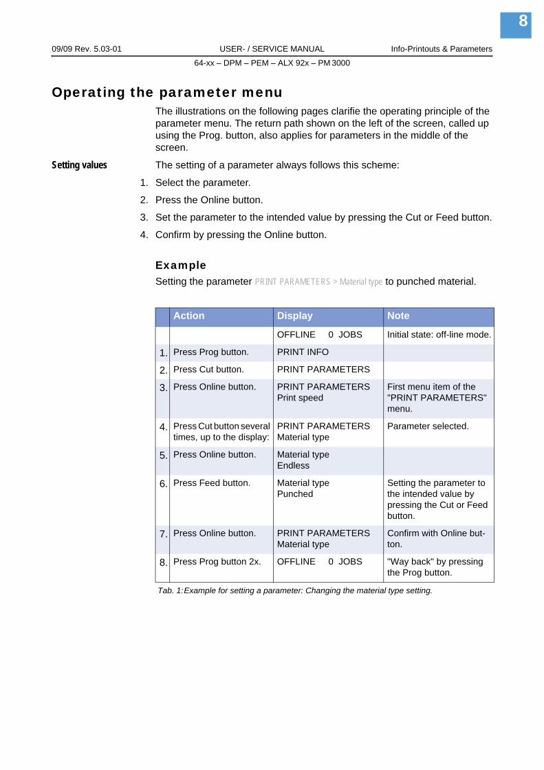
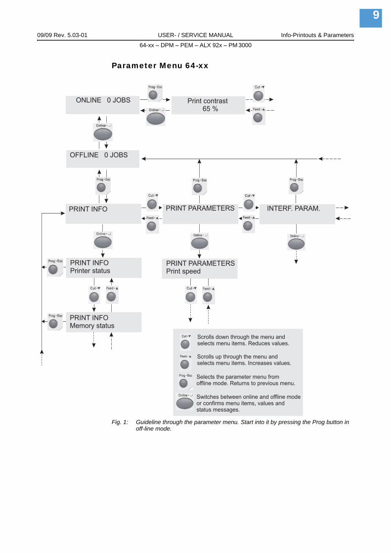
Operating the parameter menuThe illustrations on the following pages clarifie the operating principle of the parameter menu. The return path shown on the left of the screen, called up using the Prog. button, also applies for parameters in the middle of the screen.
Setting values The setting of a parameter always follows this scheme:
1. Select the parameter.
2. Press the Online button.
3. Set the parameter to the intended value by pressing the Cut or Feed button.
4. Confirm by pressing the Online button.
ExampleSetting the parameter PRINT PARAMETERS > Material type to punched material.
Action Display Note
OFFLINE 0 JOBS Initial state: off-line mode.
1. Press Prog button. PRINT INFO
2. Press Cut button. PRINT PARAMETERS
3. Press Online button. PRINT PARAMETERSPrint speed
First menu item of the "PRINT PARAMETERS" menu.
4. Press Cut button several times, up to the display:
PRINT PARAMETERSMaterial type
Parameter selected.
5. Press Online button. Material typeEndless
6. Press Feed button. Material typePunched
Setting the parameter to the intended value by pressing the Cut or Feed button.
7. Press Online button. PRINT PARAMETERSMaterial type
Confirm with Online but-ton.
8. Press Prog button 2x. OFFLINE 0 JOBS "Way back" by pressing the Prog button.
Tab. 1:Example for setting a parameter: Changing the material type setting.
09/09 Rev. 5.03-01 USER- / SERVICE MANUAL Info-Printouts & Parameters
64-xx – DPM – PEM – ALX 92x – PM 3000
9
Parameter Menu 64-xx
Fig. 1: Guideline through the parameter menu. Start into it by pressing the Prog button in off-line mode.
OFFLINE 0 JOBS
ONLINE 0 JOBS
PRINT INFO
PRINT INFOPrinter status
PRINT INFOMemory status
PRINT PARAMETERS INTERF. PARAM.
PRINT PARAMETERSPrint speed
Print contrast65 %
Scrolls down through the menu andselects menu items. Reduces values.
Scrolls up through the menu andselects menu items. Increases values.
Selects the parameter menu fromoffline mode. Returns to previous menu.
Switches between online and offline modeor confirms menu items, values andstatus messages.

09/09 Rev. 5.03-01 USER- / SERVICE MANUAL Info-Printouts & Parameters
64-xx – DPM – PEM – ALX 92x – PM 3000
10
Parameter Menu DPM / PEM / ALX 92x/PM3000
Fig. 2: Functional diagram of the DPM / PEM / ALX 92x/PM 3000 parameter menu. You get into the menu by pressing the Prog key in Offlline-Mode.
OFFLINE 0 JOBS
ONLINE 0 JOBS
PRINT INFO
PRINT INFOPrinter Status
PRINT INFOMemory Status
PRINT PARAMETERS INTERFACE PARA
PRINT PARAMETERSPrint speed
APPLY leads into deeper tiers of menu structure orselects menu items. Values are reduced.
FEED leads into higher tiers of menu structure orselects menu items. Values are enlarged.
PROG leads into the parameters menu. PROG alsocauses one step back to the last menu level.
ONLINE changes between on-line and off-line mode orconfirms menu items, values and displayed statusmessages.Z
00
26
1E
.cd
r
Print contrast65%
ESC
ESC ESC ESC
ESC
ESC
ESC
APPLY
FEED
PROG
ONLINE

09/09 Rev. 5.03-01 USER- / SERVICE MANUAL Info-Printouts & Parameters64-xx – DPM – PEM – ALX 92x
11
Overview Parameter Menus
Understanding the Parameter OverviewsThe charts in the following show all of the parameters implemented in the printer firmware. Some parameters are only visible in the parameter menu under specific preconditions. These parame-ters are provided with a gray background and a digit at the right column edge. The digit refers to a footnote describing the precondition under which the parameter is visible.

1. Only 64-xx dispe t-Emulation 4. Only with 64-08 5. Only with rewinder option 6. Only with cutter 7. Only with USI in ory 10. Only with activated MONARCH LANGUAGE INTERPRETER™ 11. Only with I/O board 12. ETERS > Autom. dot check = Continuous 16. For details read parameter description 17. Only with 64-04 RS > Dispensing edge = „User defined“ 21. Nicht mit 64-xx Spender 22. Only with an activated RFID ly if APPLICATOR PARA > Applicator type = PEP or PEP blow on 28. Not if APPLICATOR PAR LAN CF card inserted 32. Only if INTERFACE PARA > NETWORK PARAM. > Time client = „Enab
09/09 R Info-Printouts & Parameters
1264
-xx
Par
amet
ers
64-xx PPRINT (Interf. Para. continued) SYSTEM PARAMETER
Printer DHCP host name Foil end warningMemor WLAN SSID 31 Foil warn stopFont st WLAN WEP 31 Display mode 14Flashd WLAN default key 31 Dispense counter 14Service WLAN 64Bit key 1 31 Autom. dot checkDottest WLAN 64Bit key 2 31 Early dottest 15Dottest WLAN 64Bit key 3 31 Latest dottest 15Refere WLAN 64Bit key 4 31 Dottestarea from 15RFID s WLAN 128Bit key 1 31 Dottestarea to 15
WLAN 128Bit key 2 31 Print Interpret.WLAN 128Bit key 3 31 Character setsWLAN 128Bit key 4 31 Character filterWLAN com quality 31 Light sens. typeWLAN signal lev. 31 Head-sensor dist 13
Sens. punch-LS> OPTIONS Ribbon autoecon.Remote display Ribbon eco. limitOLV option Feed modeRFID option 18 Turn-on modeStandAlone Input Error reprint
EasyPlug errors> DRIVEASSIGNMENT Single job modeDrive C Head resistanceDrive D Temp. reductionDrive E Voltage offsetDrive F Expand Logo 3Drive G Miss. label tol.
FW 5
.33
nser with 4“ printhead 2. Only with 64-xx Dispenser and if SYSTEM PARAMETER > Gap detect. mode = Autom. feed back 3. Only with 8-Doterface 8. Only if SYSTEM PARAMETER > Gap detect. mode = Autom. feed back 9. Only with at least one data block stored in the flash memOnly if PRINT PARAMETERS > Punch mode = Manual 13. Only in production mode 14. Only with 64-xx dispenser 15. Only if SYSTEM PARAM/05/06 18. Only with installed RFID option 19. Only if DP INTERFACE > Interface type = USI Applicator 20. Only with SYSTEM PARAMETE
option 23. With PEM only 24. With connected remote display only 25. With Applicator Interface only 26. Only OLV option activated 27. OnA > Applicator type = LTP-LTPV or ASA 29. Availability depends on device configuration 30. Only with a CF card inserted 31. Only with a Wled“
ev. 5.03-01 USER- / SERVICE MANUAL64-xx – DPM – PEM – ALX 92x
arameter INFO PRINT PARAMETERS INTERFACE PARA (Interf. Para. continued)
status Print speed > EASYPLUGINTERPR No. of data bitsy status Feed speed Interface Parityatus Material type Spooler mode Stop bitsata status 9 Material length Printer ID No. Data synch. status Material width Spooler size Frame error endless Print direction Offline mode punched Punch offset Interface delay > CENTRONICS nce label Bar code Multip. PnP functiontatus 22 Tradit. imaging > COM1 PORT
UPC plain-copy Baud rate > NETWORK PARAM.EAN Readline No. of data bits IP AddressassignEAN sep. lines Parity IP AddressRotated Barcodes Stop bits Net maskDispense Mode 14 Data synch. Gateway addressDispensposition 14 Frame error Ethernet speedCut mode 6 Port addressCut speed 6 > COM2 PORT 11 MAC addressCut position 6 Baud rate 11 SNMP agentDouble cut 6 No. of data bits 11 SNMP password 13Rewind direction 5 Parity 11 FTP serverX – print offset Stop bits 11 FTP password 13Y – print offset Data synch. 11 WEB serverPunch mode Serial Port Mode 11 WEB admin passw. 13Punch level 12 Frame error 11 WEB supervisor p. 13
Time client> COM4 PORT Time server IP 32Baud rate Sync interval 32

1. Only 64-xx dispe t-Emulation 4. Only with 64-08 5. Only with rewinder option 6. Only with cutter 7. Only with USI in ory 10. Only with activated MONARCH LANGUAGE INTERPRETER™ 11. Only with I/O board 12. ETERS > Autom. dot check = Continuous 16. For details read parameter description 17. Only with 64-04 RS > Dispensing edge = „User defined“ 21. Nicht mit 64-xx Spender 22. Only with an activated RFID ly if APPLICATOR PARA > Applicator type = PEP or PEP blow on 28. Not if APPLICATOR PAR LAN CF card inserted 32. Only if INTERFACE PARA > NETWORK PARAM. > Time client = „Enab
09/09 R Info-Printouts & Parameters
1364
-xx
Par
amet
ers
(System 7 MLI PARAMETERS 10 I/O BOARD PARA 11
Gap de 7 Version 10 Start delay 11Foil str 7 Darkness 10 Start print mode 11Max In 7 Control Prefix 10 Reprint Signal 11Mat. en 7 Format Prefix 10 Feed 11Periph. 7 Delimiter Char 10 Pause input 11Singles 7 Label Top 10 Error output 11Dispen 7 Left Position 10 Error polarity 11Applica 7 Manual Calibrate 10 Status output 11Start m 7 Resolution 10 Status polarity 11Start so 7 Error Indication 10 End print mode 11Dispen 7 Error Checking 10Head d 9 305 DPI Scaling 10Transp Image Save Path 10Externa Command ^PR 10Signal Command ^MT 10Apply k Label Invert 10Print co Command ^JM 10Ram diFont doFree stPrint InReprintLanguaKeyboaSignal AccessRealtim
FW 5
.33
nser with 4“ printhead 2. Only with 64-xx Dispenser and if SYSTEM PARAMETER > Gap detect. mode = Autom. feed back 3. Only with 8-Doterface 8. Only if SYSTEM PARAMETER > Gap detect. mode = Autom. feed back 9. Only with at least one data block stored in the flash memOnly if PRINT PARAMETERS > Punch mode = Manual 13. Only in production mode 14. Only with 64-xx dispenser 15. Only if SYSTEM PARAM/05/06 18. Only with installed RFID option 19. Only if DP INTERFACE > Interface type = USI Applicator 20. Only with SYSTEM PARAMETE
option 23. With PEM only 24. With connected remote display only 25. With Applicator Interface only 26. Only OLV option activated 27. OnA > Applicator type = LTP-LTPV or ASA 29. Availability depends on device configuration 30. Only with a CF card inserted 31. Only with a Wled“
ev. 5.03-01 USER- / SERVICE MANUAL64-xx – DPM – PEM – ALX 92x
Param. continued) APPLICATOR PARA 25 OLV PARAMETERS 26 DP INTERFACE
tect. mode Applicator type 25 Verify mode 26 Interface typeetching 13/21 Application mode 25 Ref Decode 26 Start delayitFeedback 2 Start print mode 25 Decodability 26 Start print moded detect. Start error stop 25 Modulation 26 End print mode device APSF sensor res. 25 Defects 26 Reprint signaltartquant Start delay 25 Edge Contrast 26 Ribbon signalsing mode 14 Dwell time 25/27 Rmin/Rmax 26 Material signaltion mode 14 Blow on time 25/28 Symbol Contrast 26 Feed inputode Restart delay 25 PCS 26 Pause inputurce 14 Position timeout 25 R (white) 26 Start error stop
sing edge 14 R (black) 26 Internal inputsisp dist 20 Ratio 26 Apply mode 1ort mode 14 ANSI Symbolgrade 26l signal Dist. head-beam 26
edge Cancel. printing 26ey 13 Reprint quantity 26ntrast OLV Mode 26sk sizewnl. area
ore sizefo Mode functiongerd
/ buzzer authoriz.e clock
1. Only 64-xx dispenser with 4“ printhead 2. Only with 64-xx Dispenser and if SYSTEM PARAMETER > Gap detect. mode = Autom. feed back 3. Only with 8-Dot-Emulation 4. Only with 64-08 5. Only with rewinder option 6. Only with cutter 7. Only with USI interface 8. Only if SYSTEM PARAMETER > Gap detect. mode = Autom. feed back 9. Only with at least one data block stored in the flash memory 10. Only with activated MONARCH LANGUAGE INTERPRETER™ 11. Only with I/O board 12. Only if PRINT PARAMETERS > Punch mode = Manual 13. Only in production mode 14. Only with 64-xx dispenser 15. Only if SYSTEM PARAMETERS > Autom. dot check = Continuous 16. For details read parameter description 17. Only with 64-04/05/06 18. Only with installed RFID option 19. Only if DP INTERFACE > Interface type = USI Applicator 20. Only with SYSTEM PARAMETERS > Dispensing edge = „User defined“ 21. Nicht mit 64-xx Spender 22. Only with an activated RFID option 23. With PEM only 24. With connected remote display only 25. With Applicator Interface only 26. Only OLV option activated 27. Only if APPLICATOR PARA > Applicator type = PEP or PEP blow on 28. Not if APPLICATOR PARA > Applicator type = LTP-LTPV or ASA 29. Availability depends on device configuration 30. Only with a CF card inserted 31. Only with a WLAN CF card inserted 32. Only if INTERFACE PARA > NETWORK PARAM. > Time client = „Enabled“
09/09 Rev. 5.03-01 USER- / SERVICE MANUAL Info-Printouts & Parameters64-xx – DPM – PEM – ALX 92x
1464
-xx
Par
amet
ers
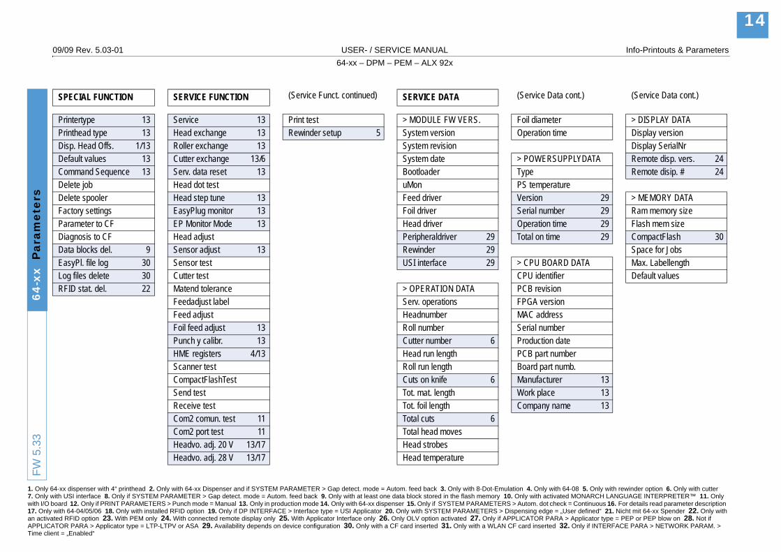
SPECIAL FUNCTION SERVICE FUNCTION (Service Funct. continued) SERVICE DATA (Service Data cont.) (Service Data cont.)
Printertype 13 Service 13 Print test > MODULE FW VERS. Foil diameter > DISPLAY DATAPrinthead type 13 Head exchange 13 Rewinder setup 5 System version Operation time Display versionDisp. Head Offs. 1/13 Roller exchange 13 System revision Display SerialNrDefault values 13 Cutter exchange 13/6 System date > POWERSUPPLYDATA Remote disp. vers. 24Command Sequence 13 Serv. data reset 13 Bootloader Type Remote disip. # 24Delete job Head dot test uMon PS temperatureDelete spooler Head step tune 13 Feed driver Version 29 > MEMORY DATAFactory settings EasyPlug monitor 13 Foil driver Serial number 29 Ram memory sizeParameter to CF EP Monitor Mode 13 Head driver Operation time 29 Flash mem sizeDiagnosis to CF Head adjust Peripheraldriver 29 Total on time 29 CompactFlash 30Data blocks del. 9 Sensor adjust 13 Rewinder 29 Space for JobsEasyPl. file log 30 Sensor test USI interface 29 > CPU BOARD DATA Max. LabellengthLog files delete 30 Cutter test CPU identifier Default valuesRFID stat. del. 22 Matend tolerance > OPERATION DATA PCB revision
Feedadjust label Serv. operations FPGA versionFeed adjust Headnumber MAC addressFoil feed adjust 13 Roll number Serial numberPunch y calibr. 13 Cutter number 6 Production dateHME registers 4/13 Head run length PCB part numberScanner test Roll run length Board part numb.CompactFlashTest Cuts on knife 6 Manufacturer 13Send test Tot. mat. length Work place 13Receive test Tot. foil length Company name 13Com2 comun. test 11 Total cuts 6Com2 port test 11 Total head movesHeadvo. adj. 20 V 13/17 Head strobesHeadvo. adj. 28 V 13/17 Head temperature
FW 5
.33

1. Only 64-xx dispe t-Emulation 4. Only with 64-08 5. Only with rewinder option 6. Only with cutter 7. Only with USI in ory 10. Only with activated MONARCH LANGUAGE INTERPRETER™ 11. Only with I/O board 12. ETERS > Autom. dot check = Continuous 16. For details read parameter description 17. Only with 64-04 RS > Dispensing edge = „User defined“ 21. Nicht mit 64-xx Spender 22. Only with an activated RFID ly if APPLICATOR PARA > Applicator type = PEP or PEP blow on 28. Not if APPLICATOR PAR LAN CF card inserted 32. Only if INTERFACE PARA > NETWORK PARAM. > Time client = „Enab
09/09 R Info-Printouts & Parameters
15D
PM
/PE
M/A
LX 9
2x P
aram
eter
s
DPM /PRINT (INTERFACE PARA cont.) SYSTEM PARAMETER
Printer WLAN WEP 31 Head disp distMemor WLAN default key 31 Speed unitFont st WLAN 64Bit key 1 31 Cover open errorService WLAN 64Bit key 2 31 Foil end warningDottest WLAN 64Bit key 3 31 Foil warn stopDottest WLAN 64Bit key 4 31 Display modeRefere WLAN 128Bit key 1 31 Dispense counterRFID s WLAN 128Bit key 2 31 Autom. dot check
WLAN 128Bit key 3 31 Early dottest 15WLAN 128Bit key 4 31 Latest dottest 15WLAN com quality 31 Dottestarea from 15WLAN signal lev. 31 Dottestarea to 15
Print Interpret.> OPTIONEN Character setsRemote display Character filterOLV option Light sens. typeRFID option 18 Head-sensor dist. 13StandAlone Input Sens. punch-LS
Ribbon autoecon.> DRIVEASSIGNMENT Ribbon eco. limitDrive C Feed modeDrive D Turn-on modeDrive E Error reprintDrive F EasyPlug errorsDrive G Single job mode
Head resistanceTemp. reductionVoltage offsetFW
5.3
3
nser with 4“ printhead 2. Only with 64-xx Dispenser and if SYSTEM PARAMETER > Gap detect. mode = Autom. feed back 3. Only with 8-Doterface 8. Only if SYSTEM PARAMETER > Gap detect. mode = Autom. feed back 9. Only with at least one data block stored in the flash memOnly if PRINT PARAMETERS > Punch mode = Manual 13. Only in production mode 14. Only with 64-xx dispenser 15. Only if SYSTEM PARAM/05/06 18. Only with installed RFID option 19. Only if DP INTERFACE > Interface type = USI Applicator 20. Only with SYSTEM PARAMETE
option 23. With PEM only 24. With connected remote display only 25. With Applicator Interface only 26. Only OLV option activated 27. OnA > Applicator type = LTP-LTPV or ASA 29. Availability depends on device configuration 30. Only with a CF card inserted 31. Only with a Wled“
ev. 5.03-01 USER- / SERVICE MANUAL64-xx – DPM – PEM – ALX 92x
PEM / ALX 92x Parameter INFO PRINT PARAMETERS INTERFACE PARA (INTERFACE PARA cont.)
status Print speed > EASYPLUGINTERPR Parityy status Feed speed Interface Data synch.atus Material type Spooler mode Stop bits status Material length Printer ID No. Frame error endless Material width Spooler size punched Print direction Offline mode > CENTRONICS nce label Punch offset Interface delay PnP functiontatus 22 Bar code Multip.
Tradit. imaging > COM1 PORT > NETWORK PARAM.UPC plain-copy Baud rate IP AddressassignEAN Readline No. of data bits IP AddressEAN sep. lines Parity Net maskRotated Barcodes Stop bits Gateway addressDispense Mode Data synch. Ethernet speedDispensposition Frame error Port addressX – print offset MAC addressY – print offset > COM2 PORT 11 SNMP agentPunch mode Baud rate 11 SNMP password 13Punch level 12 No. of data bits 11 FTP server
Parity 11 FTP password 13Stop bits 11 WEB serverData synch. 11 WEB admin passw. 13Serial Port Mode 11 WEB supervisor p. 13Frame error 11 Time client
Time server IP 32> COM4 PORT Sync interval 32Baud rate DHCP host nameNo. of data bits WLAN SSID 31

1. Only 64-xx dispe t-Emulation 4. Only with 64-08 5. Only with rewinder option 6. Only with cutter 7. Only with USI in ory 10. Only with activated MONARCH LANGUAGE INTERPRETER™ 11. Only with I/O board 12. ETERS > Autom. dot check = Continuous 16. For details read parameter description 17. Only with 64-04 RS > Dispensing edge = „User defined“ 21. Nicht mit 64-xx Spender 22. Only with an activated RFID ly if APPLICATOR PARA > Applicator type = PEP or PEP blow on 28. Not if APPLICATOR PAR LAN CF card inserted 32. Only if INTERFACE PARA > NETWORK PARAM. > Time client = „Enab
09/09 R Info-Printouts & Parameters
16D
PM
/PE
M/A
LX 9
2x P
aram
eter
s
(System 7 MLI PARAMETERS 10 I/O BOARD PARA 11
Expand 7 Version 10 Start delay 11Miss. la 7 Darkness 10 Start print mode 11Gap de 7 Control Prefix 10 Reprint Signal 11Foil str 7 Format Prefix 10 Feed 11Max In 7 Delimiter Char 10 Pause input 11Mat. en 7 Label Top 10 Error output 11Periph. 7 Left Position 10 Error polarity 11Singles 7 Manual Calibrate 10 Status output 11Dispen 7 Resolution 10 Status polarity 11Applica 7 Error Indication 10 End print mode 11Start m 7 Error Checking 10Externa 9 305 DPI Scaling 10Signal Image Save Path 10Apply k Command ^PR 10Print co Command ^MT 10Ram di Label Invert 10Font do Command ^JM 10Free stPrint inReprintLanguaKeyboaSignal AccessRealtimMateria
FW 5
.33
nser with 4“ printhead 2. Only with 64-xx Dispenser and if SYSTEM PARAMETER > Gap detect. mode = Autom. feed back 3. Only with 8-Doterface 8. Only if SYSTEM PARAMETER > Gap detect. mode = Autom. feed back 9. Only with at least one data block stored in the flash memOnly if PRINT PARAMETERS > Punch mode = Manual 13. Only in production mode 14. Only with 64-xx dispenser 15. Only if SYSTEM PARAM/05/06 18. Only with installed RFID option 19. Only if DP INTERFACE > Interface type = USI Applicator 20. Only with SYSTEM PARAMETE
option 23. With PEM only 24. With connected remote display only 25. With Applicator Interface only 26. Only OLV option activated 27. OnA > Applicator type = LTP-LTPV or ASA 29. Availability depends on device configuration 30. Only with a CF card inserted 31. Only with a Wled“
ev. 5.03-01 USER- / SERVICE MANUAL64-xx – DPM – PEM – ALX 92x
Param. cont.) APPLICATOR PARA 25 OLV PARAMETERS 26 DP INTERFACE
Logo 3 Applicator type 25 Verify mode 26 Interface typebel tol. Application mode 25 Ref Decode 26 Start delaytect. mode Start print mode 25 Decodability 26 Start print mode
etching 13/23 Start error stop 25 Modulation 26 End print modeitFeedback 8 APSF sensor res. 25 Defects 26 Reprint signald detect. Start delay 25 Edge Contrast 26 Ribbon signal device 13/16 Dwell time 25/27 Rmin/Rmax 26 Material signaltartquant Blow on time 25/28 Symbol Contrast 26 Feed inputsing Mode Restart delay 25 PCS 26 Pause inputtion mode Position timeout 25 R (white) 26 Start error stopode R (black) 26 Internal inputsl signal Ratio 26 Apply mode 1
edge ANSI Symbolgrade 26ey 13 Dist. head-beam 26ntrast Cancel. printing 26sk size Reprint quantity 26wnl. area OLV Mode 26
ore sizefo mode functiongerd
/ buzzer authoriz.e clockl feed

1. Only 64-xx dispenser with 4“ printhead 2. Only with 64-xx Dispenser and if SYSTEM PARAMETER > Gap detect. mode = Autom. feed back 3. Only with 8-Dot-Emulation 4. Only with 64-08 5. Only with rewinder option 6. Only with cutter 7. Only with USI interface 8. Only if SYSTEM PARAMETER > Gap detect. mode = Autom. feed back 9. Only with at least one data block stored in the flash memory 10. Only with activated MONARCH LANGUAGE INTERPRETER™ 11. Only with I/O board 12. Only if PRINT PARAMETERS > Punch mode = Manual 13. Only in production mode 14. Only with 64-xx dispenser 15. Only if SYSTEM PARAMETERS > Autom. dot check = Continuous 16. For details read parameter description 17. Only with 64-04/05/06 18. Only with installed RFID option 19. Only if DP INTERFACE > Interface type = USI Applicator 20. Only with SYSTEM PARAMETERS > Dispensing edge = „User defined“ 21. Nicht mit 64-xx Spender 22. Only with an activated RFID option 23. With PEM only 24. With connected remote display only 25. With Applicator Interface only 26. Only OLV option activated 27. Only if APPLICATOR PARA > Applicator type = PEP or PEP blow on 28. Not if APPLICATOR PARA > Applicator type = LTP-LTPV or ASA 29. Availability depends on device configuration 30. Only with a CF card inserted 31. Only with a WLAN CF card inserted 32. Only if INTERFACE PARA > NETWORK PARAM. > Time client = „Enabled“
09/09 Rev. 5.03-01 USER- / SERVICE MANUAL Info-Printouts & Parameters64-xx – DPM – PEM – ALX 92x
17D
PM
/PE
M/A
LX 9
2x P
aram
eter
s
SPECIAL FUNCTION SERVICE FUNCTION SERVICE DATA (Service Data cont.) (Service Data cont.)
Printer type 13 Service 13 > PERIPHERAL DATA Serial number 29 > MEMORY DATAPrinthead type 13 Head exchange 13 System version Operation time 29 Ram memory sizeDefault values 13 Roller exchange 13 Feed driver Total on time 29 Flash mem sizeCommand Sequence 13 Cutter exchange 13/6 Foil driver Space for JobsDelete job Serv. data reset 13 Head driver > CPU BOARD DATA Max. LabellengthDelete spooler Head dot test Rewinder 29 CPU identifier Default valuesFactory settings Head step tune 13 USI interface 29 Syst. controllerParameter to CF 30 EasyPlug monitor 13 Applicator int. 29 PCB revisionEasyPl. file log 30 EP Monitor Mode MAC addressLog files delete 30 Head adjust > OPERATION DATA Serial numberRFID stat. del. Sensor adjust 13 Serv. operations Production date
Sensor test Headnumber PCB part numberHME registers Roll number Board part numb.Cutter test Head run length Manufacturer 13Matend tolerance Roll run length Work place 13Feed adjust Tot. mat. length Company name 13Punch y calibr. 13 Tot. foil lengthFoil feed adjust 13 Total head moves > DISPLAY DATAScanner test Head strobes Display versionCompactFlashTest Head temperature Display serialnrSend test Foil diameter Remote disp. vers. 24Receive test Dispensing cycl. Remote disip. # 24Com2 comun. test 13 Operation timeCom2 port test 13Print test > POWERSUPPLYDATARewinder setup Type
PS temperatureVersion 29FW
5.3
3

1. Only 64-xx dispenser with 4“ printhead 2. Only with 64-xx Dispenser and if SYSTEM PARAMETER > Gap detect. mode = Autom. feed back 3. Only with 8-Dot-Emulation 4. Only with 64-08 5. Only with rewinder option 6. Only with cutter 7. Only with USI interface 8. Only if SYSTEM PARAMETER > Gap detect. mode = Autom. feed back 9. Only with at least one data block stored in the flash memory 10. Only with activated MONARCH LANGUAGE INTERPRETER™ 11. Only with I/O board 12. Only if PRINT PARAMETERS > Punch mode = Manual 13. Only in production mode 14. Only with 64-xx dispenser 15. Only if SYSTEM PARAMETERS > Autom. dot check = Continuous 16. For details read parameter description 17. Only with 64-04/05/06 18. Only with installed RFID option 19. Only if DP INTERFACE > Interface type = USI Applicator 20. Only with SYSTEM PARAMETERS > Dispensing edge = „User defined“ 21. Nicht mit 64-xx Spender 22. Only with an activated RFID option 23. With PEM only 24. With connected remote display only 25. With Applicator Interface only 26. Only OLV option activated 27. Only if APPLICATOR PARA > Applicator type = PEP or PEP blow on 28. Not if APPLICATOR PARA > Applicator type = LTP-LTPV or ASA 29. Availability depends on device configuration 30. Only with a CF card inserted 31. Only with a WLAN CF card inserted 32. Only if INTERFACE PARA > NETWORK PARAM. > Time client = „Enabled“
09/09 Rev. 5.03-01 USER- / SERVICE MANUAL Info-Printouts & Parameters64-xx – DPM – PEM – ALX 92x
18P
M30
00 P
aram
eter
s
PM 3000PRINT INFO PRINT PARAMETERS INTERFACE PARA (INTERFACE PARA cont.) (INTERFACE PARA cont.) SYSTEM PARAMETER
Printer status Print speed > EASYPLUGINTERPR > NETWORK PARAM. WLAN 128Bit key 3 31 Cover open errorMemory status Feed speed Interface IP Addressassign WLAN 128Bit key 4 31 Foil end warningFont status Material type Spooler mode IP Address WLAN com quality 31 Foil warn stopFlashdata status 9 Material length Printer ID No. Net mask WLAN signal lev. 31 Autom. dot checkService status Material width Spooler size Gateway address WLAN com quality 31 Early dottest 15Dottest endless Print direction Offline mode Port address WLAN signal lev. 31 Latest dottest 15Dottest punched Punch offset Interface delay Ethernet speed Dottestarea from 15Reference label Bar code Multip. MAC address > OPTIONS Dottestarea to 15RFID status 22 Tradit. imaging > COM1 PORT SNMP Agent Remote display Print Interpret.
UPC plain-copy Baud rate SNMP Password 13 OLV option Character setsEAN Readline No. of data bits FTP server StandAlone input Character filterEAN sep. lines Parity FTP password 13 Light sens. typeRotated Barcodes Stop bits WEB server > DRIVEASSIGNMENT Head-sensor dist. 13Cut mode 6 Data synch. WEB admin passw. 13 Drive C Sens. punch-LSCut speed 6 Frame error WEB supervisor p. 13 Drive D Ribbon autoecon.Cut position 6 Time client Drive E Ribbon eco. limitDouble cut 6 > COM4 PORT Time server IP 32 Drive F Feed modeX – print offset Baud rate Sync interval 32 Drive G Turn-on modeY – print offset Anzahl Datenbits DHCP host name Error reprintPunch mode Parity WLAN SSID 31 EasyPlug errorsPunch level 12 Stop Bits WLAN WEP 31 Single job mode
Data synch. WLAN default key 31 Head resistanceFrame error WLAN 64Bit key 1 31 Temp. reduction
WLAN 64Bit key 2 31 Voltage offset> CENTRONICS WLAN 64Bit key 3 31 Expand Logo 3PnP function WLAN 64Bit key 4 31 Miss. label tol.
WLAN 128Bit key 1 31 Gap detect. modeWLAN 128Bit key 2 31 Foil stretching 13FW
5.3
3

1. Only 64-xx dispenser with 4“ printhead 2. Only with 64-xx Dispenser and if SYSTEM PARAMETER > Gap detect. mode = Autom. feed back 3. Only with 8-Dot-Emulation 4. Only with 64-08 5. Only with rewinder option 6. Only with cutter 7. Only with USI interface 8. Only if SYSTEM PARAMETER > Gap detect. mode = Autom. feed back 9. Only with at least one data block stored in the flash memory 10. Only with activated MONARCH LANGUAGE INTERPRETER™ 11. Only with I/O board 12. Only if PRINT PARAMETERS > Punch mode = Manual 13. Only in production mode 14. Only with 64-xx dispenser 15. Only if SYSTEM PARAMETERS > Autom. dot check = Continuous 16. For details read parameter description 17. Only with 64-04/05/06 18. Only with installed RFID option 19. Only if DP INTERFACE > Interface type = USI Applicator 20. Only with SYSTEM PARAMETERS > Dispensing edge = „User defined“ 21. Nicht mit 64-xx Spender 22. Only with an activated RFID option 23. With PEM only 24. With connected remote display only 25. With Applicator Interface only 26. Only OLV option activated 27. Only if APPLICATOR PARA > Applicator type = PEP or PEP blow on 28. Not if APPLICATOR PARA > Applicator type = LTP-LTPV or ASA 29. Availability depends on device configuration 30. Only with a CF card inserted 31. Only with a WLAN CF card inserted 32. Only if INTERFACE PARA > NETWORK PARAM. > Time client = „Enabled“
09/09 Rev. 5.03-01 USER- / SERVICE MANUAL Info-Printouts & Parameters64-xx – DPM – PEM – ALX 92x
19P
M30
00 P
aram
eter
s
(System Param. cont.) OLV PARAMETERS 26 DP INTERFACE MLI PARAMETERS 10 I/O BOARD PARA 11 SPECIAL FUNCTION
Foil stretching 13 Verify mode 26 Interface type Version 10 Start delay 11 Printer type 13Max InitFeedback 8 Ref Decode 26 Start delay Darkness 10 Start print mode 11 Printhead type 13Mat. end detect. Decodability 26 Start print mode Control Prefix 10 Reprint Signal 11 Sensor type 13Periph. device 16 Modulation 26 End print mode Format Prefix 10 Feed 11 Default values 13Singlestartquant Defects 26 Reprint signal Delimiter Char 10 Pause input 11 Command Sequence 13Start mode Edge Contrast 26 Ribbon signal Label Top 10 Error output 11 Delete jobExternal signal Rmin/Rmax 26 Material signal Left Position 10 Error polarity 11 Delete spoolerSignal edge Symbol Contrast 26 Feed input Manual Calibrate 10 Status output 11 Factory settingsApply key 13 PCS 26 Pause input Resolution 10 Status polarity 11 Parameter to CF 30Print contrast R (white) 26 Start error stop Error Indication 10 End print mode 11 EasyPl. file log 30Ram disk size R (black) 26 Internal inputs Error Checking 10 Log files delete 30Font downl. area Ratio 26 Apply mode 305 DPI Scaling 10 RFID stat. del.Free store size ANSI Symbolgrade 26 Image Save Path 10Print info mode Dist. head-beam 26 Command ^PR 10Reprint function Cancel. printing 26 Command ^MT 10Language Reprint quantity 26 Label Invert 10Keyboard OLV Mode 26 Command ^JM 10Signal / buzzerAccess authoriz.Realtime clockMaterial feed
FW 5
.33

1. Only 64-xx dispenser with 4“ printhead 2. Only with 64-xx Dispenser and if SYSTEM PARAMETER > Gap detect. mode = Autom. feed back 3. Only with 8-Dot-Emulation 4. Only with 64-08 5. Only with rewinder option 6. Only with cutter 7. Only with USI interface 8. Only if SYSTEM PARAMETER > Gap detect. mode = Autom. feed back 9. Only with at least one data block stored in the flash memory 10. Only with activated MONARCH LANGUAGE INTERPRETER™ 11. Only with I/O board 12. Only if PRINT PARAMETERS > Punch mode = Manual 13. Only in production mode 14. Only with 64-xx dispenser 15. Only if SYSTEM PARAMETERS > Autom. dot check = Continuous 16. For details read parameter description 17. Only with 64-04/05/06 18. Only with installed RFID option 19. Only if DP INTERFACE > Interface type = USI Applicator 20. Only with SYSTEM PARAMETERS > Dispensing edge = „User defined“ 21. Nicht mit 64-xx Spender 22. Only with an activated RFID option 23. With PEM only 24. With connected remote display only 25. With Applicator Interface only 26. Only OLV option activated 27. Only if APPLICATOR PARA > Applicator type = PEP or PEP blow on 28. Not if APPLICATOR PARA > Applicator type = LTP-LTPV or ASA 29. Availability depends on device configuration 30. Only with a CF card inserted 31. Only with a WLAN CF card inserted 32. Only if INTERFACE PARA > NETWORK PARAM. > Time client = „Enabled“
09/09 Rev. 5.03-01 USER- / SERVICE MANUAL Info-Printouts & Parameters64-xx – DPM – PEM – ALX 92x
20P
M30
00 P
aram
eter
s
SERVICE FUNCTION SERVICE DATA (Service Data cont.) (Service Data cont.)
Service 13 > MODULE FW VERS. > POWERSUPPLYDATA > MEMORY DATAHead exchange 13 System version Type Ram memory sizeRoller exchange 13 System revision PS temperature Flash mem sizeCutter exchange 13/6 Bootloader Version 29 CompactFlashServ. data reset 13 uMon Serial number 29 Space for JobsHead dot test Feed driver Standby+On time 29 Max. LabellengthHead step tune 13 Foil driver On time 29 Default valuesEasyPlug monitor 13 Head driverEP Monitor Mode 13 USI interface > CPU BOARD DATAHead adjust CPU identifierSensor adjust 13 > OPERATION DATA PCB revisionSensor test Serv. operations FPGA versionCutter test Headnumber MAC addressMatend tolerance Roll number Serial numberFeed label Cutter number 6 Production dateFeed adjust Head run length PCB part numberPunch y calibr. 13 Roll run length Board part numb.Foil feed adjust 13 Cuts on knife 6 Manufacturer 13HME registers 13 Tot. mat. length Work place 13Scanner test Tot. foil length Company name 13CompactFlashTest Total cuts 6Send test Total head moves > DISPLAY DATAReceive test Head strobes Display versionPrint test Head temperature Display serialnr
Foil diameter Remote disp. vers. 24Operation time Remote disip. # 24
FW 5
.33

09/09 Rev. 5.03-01 USER- / SERVICE MANUAL Info-Printouts & Parameters
64-xx – DPM – PEM – ALX 92x – PM 3000
21
Alphabetical Parameter List305 DPI Scaling . . . . . . . . . 115Access authoriz. . . . . . . . . . . . 92ANSI symbol grade. . . . . . . 105Application mode . . . . . . . . . . 86Application mode . . . . . . . . . . 96Applicator int. . . . . . . . . . . . 136Applicator type . . . . . . . . . . . . 95Apply key . . . . . . . . . . . . . . . . 89Apply mode. . . . . . . . . . . . . 112APSF sensor res. . . . . . . . . . . 97Autom. dot check . . . . . . . . . . 73Bar code multip. . . . . . . . . . . . 39Baud rate . . . . . . . . . . . . . . . . 53Baud rate . . . . . . . . . . . . . . . . 54Baud rate . . . . . . . . . . . . . . . . 56Blow on time . . . . . . . . . . . . . . 98Board part numb. . . . . . . . . 142Bootloader . . . . . . . . . . . . . 135Cancel. printing. . . . . . . . . . 106Character filter . . . . . . . . . . . . 78Character sets . . . . . . . . . . . . 77Com2 commun. test . . . . . . 133Com2 port test . . . . . . . . . . 133Command ^JM. . . . . . . . . . 117Command ^MT . . . . . . . . . 116Command ^PR . . . . . . . . . 116Command sequence. . . . . . 120CompactFlash. . . . . . . . . . . 144CompactFlashTest . . . . . . . 129Company name . . . . . . . . . 142Control Prefix . . . . . . . . . . . 113Cover open error. . . . . . . . . . . 70CPU identifier . . . . . . . . . . . 141Cut mode . . . . . . . . . . . . . . . . 46Cut position. . . . . . . . . . . . . . . 48Cut speed . . . . . . . . . . . . . . . . 48Cuts on knife. . . . . . . . . . . . 137Cutter exchange . . . . . . . . . 125Cutter number. . . . . . . . . . . 137
Cutter test. . . . . . . . . . . . . . . 128Darkness . . . . . . . . . . . . . . . 113Data blocks del. . . . . . . . . . . 121Data synch. . . . . . . . . . . . . . . 54Data synch. . . . . . . . . . . . . . . 55Data synch. . . . . . . . . . . . . . . 56Decodability . . . . . . . . . . . . . 103Default Values . . . . . . . . . . . 120Default values. . . . . . . . . . . . 144Defects . . . . . . . . . . . . . . . . . 104Delete job . . . . . . . . . . . . . . . 120Delete spooler . . . . . . . . . . . 120Delimiter Char . . . . . . . . . . . 114DHCP host name . . . . . . . . . . 63Diagnosis to CF . . . . . . . . . . 121Disp. Head Offs. . . . . . . . . . . 119Dispense counter . . . . . . . . . . 72Dispense Mode . . . . . . . . . . . 41Dispenseposition . . . . . . . . . . 44Dispensing cycl. . . . . . . . . . . 139Dispensing edge. . . . . . . . . . . 88Dispensing mode . . . . . . . . . . 86Display mode . . . . . . . . . . . . . 71Display SerialNr . . . . . . . . . . 142Display version. . . . . . . . . . . 142Dist. head-beam. . . . . . . . . . 106Dottest endless. . . . . . . . . . . . 32Dottest punched . . . . . . . . . . . 32Dottestarea from. . . . . . . . . . . 75Dottestarea to. . . . . . . . . . . . . 75Double cut . . . . . . . . . . . . . . . 48Drive C . . . . . . . . . . . . . . . . . . 68Drive D . . . . . . . . . . . . . . . . . . 68Drive E . . . . . . . . . . . . . . . . . . 68Drive F . . . . . . . . . . . . . . . . . . 69Drive G . . . . . . . . . . . . . . . . . . 69Dwell time. . . . . . . . . . . . . . . . 97EAN Readline. . . . . . . . . . . . . 40EAN sep. lines . . . . . . . . . . . . 41
Early dottest. . . . . . . . . . . . . . 73EasyPl. file log . . . . . . . . . . . 122EasyPlug error . . . . . . . . . . . . 80EasyPlug monitor. . . . . . . . . 126Edge contrast. . . . . . . . . . . . 104End print mode . . . . . . . . . . 102End print mode . . . . . . . . . . 108EP Monitor Mode . . . . . . . . . 127Error Checking. . . . . . . . . . . 115Error Indication . . . . . . . . . . 115Error output . . . . . . . . . . . . . 101Error Polarity . . . . . . . . . . . . 101Error reprint . . . . . . . . . . . . . . 80Ethernet speed . . . . . . . . . . . 58Expand Logo . . . . . . . . . . . . . 82External signal . . . . . . . . . . . . 85Factory settings . . . . . . . . . . 120Feed adjust . . . . . . . . . . . . . 129Feed driver. . . . . . . . . . . . . . 135Feed input . . . . . . . . . . . . . . 100Feed input . . . . . . . . . . . . . . 110Feed mode. . . . . . . . . . . . . . . 80Feed speed . . . . . . . . . . . . . . 35Feedadjust label . . . . . . . . . 128Flash mem size . . . . . . . . . . 143Flashdata status . . . . . . . . . . 30Foil diameter . . . . . . . . . . . . 139Foil driver . . . . . . . . . . . . . . . 135Foil end warning . . . . . . . . . . 71Foil feed adjust . . . . . . . . . . 129Foil stretching . . . . . . . . . . . . 84Foil warn stop . . . . . . . . . . . . 71Font downl. area . . . . . . . . . . 90Font status . . . . . . . . . . . . . . . 27Format Prefix . . . . . . . . . . . . 114FPGA version . . . . . . . . . . . 141Frame error . . . . . . . . . . . . . . 54Frame error . . . . . . . . . . . . . . 55Frame error . . . . . . . . . . . . . . 56

09/09 Rev. 5.03-01 USER- / SERVICE MANUAL Info-Printouts & Parameters
64-xx – DPM – PEM – ALX 92x – PM 3000
22
Free store size . . . . . . . . . . . . 91FTP password. . . . . . . . . . . . . 59FTP server . . . . . . . . . . . . . . . 59Gap detect mode . . . . . . . . . . 83Gateway address . . . . . . . . . . 58Head adjust. . . . . . . . . . . . . 127Head disp dist . . . . . . . . . . . . . 88Head disp dist. . . . . . . . . . . . . 70Head dot test . . . . . . . . . . . 125Head driver . . . . . . . . . . . . . 136Head exchange. . . . . . . . . . 124Head resistance . . . . . . . . . . . 81Head run length . . . . . . . . . 137Head step tune . . . . . . . . . . 126Head strobes . . . . . . . . . . . 138Head temperature. . . . . . . . 138Headnumber . . . . . . . . . . . . 137Head-sensor dist. . . . . . . . . . . 78Headvo. adj. 20 V . . . . . . . . 133Headvo. adj. 28 V . . . . . . . . 134HME registers . . . . . . . . . . . 127Image Save Path . . . . . . . . 116Interface delay . . . . . . . . . . . . 52Interface type . . . . . . . . . . . 107Interface . . . . . . . . . . . . . . . . . 51Internal inputs . . . . . . . . . . . 111IP address. . . . . . . . . . . . . . . . 57IP addressassign . . . . . . . . . . 57Keyboard . . . . . . . . . . . . . . . . 92Label Invert . . . . . . . . . . . . . 116Label Top . . . . . . . . . . . . . . 114Language . . . . . . . . . . . . . . . . 92Latest dottest . . . . . . . . . . . . . 74Left Position . . . . . . . . . . . . 114Light sens. type. . . . . . . . . . . . 78Log files delete . . . . . . . . . . 122MAC address . . . . . . . . . . . 141MAC address . . . . . . . . . . . . . 58Manual Calibrate. . . . . . . . . 114Manufacturer. . . . . . . . . . . . 142
Mat. signal stop . . . . . . . . . . 110Mat.end detect.. . . . . . . . . . . . 84Matend tolerance . . . . . . . . . 128Material feed. . . . . . . . . . . . . . 94Material length . . . . . . . . . . . . 36Material signal . . . . . . . . . . . 109Material type. . . . . . . . . . . . . . 36Material width . . . . . . . . . . . . . 36Max InitFeedback. . . . . . . . . . 84Max. Labellength . . . . . . . . . 144Memory status . . . . . . . . . . . . 26Miss. label tol.. . . . . . . . . . . . . 83Modulation . . . . . . . . . . . . . . 103Net mask . . . . . . . . . . . . . . . . 57No. of data bits . . . . . . . . . . . . 53No. of data bits . . . . . . . . . . . . 54No. of data bits . . . . . . . . . . . . 56Offline mode. . . . . . . . . . . . . . 52OLV Option. . . . . . . . . . . . . . . 66On time. . . . . . . . . . . . . . . . . 141Operation time . . . . . . . . . . . 139Parameter to CF. . . . . . . . . . 121Parity . . . . . . . . . . . . . . . . . . . 53Parity . . . . . . . . . . . . . . . . . . . 54Parity . . . . . . . . . . . . . . . . . . . 56Pause input . . . . . . . . . . . . . 100Pause input . . . . . . . . . . . . . 110PCB part number . . . . . . . . . 142PCB revision. . . . . . . . . . . . . 141PCS . . . . . . . . . . . . . . . . . . . 104Periph. device. . . . . . . . . . . . . 85Peripheraldriver . . . . . . . . . . 136PnP function. . . . . . . . . . . . . . 57Port address. . . . . . . . . . . . . . 58Position timeout . . . . . . . . . . . 98Print contrast . . . . . . . . . . . . . 89Print direction . . . . . . . . . . . . . 37Print info mode . . . . . . . . . . . . 91Print Interpret.. . . . . . . . . . . . . 76Print speed . . . . . . . . . . . . . . . 35
Printer ID No. . . . . . . . . . . . . . 52Printer status . . . . . . . . . . . . . 24Printer type . . . . . . . . . . . . . 118Printhead type . . . . . . . . . . . 119Printtest . . . . . . . . . . . . . . . . 134Production date . . . . . . . . . . 141PS temperature . . . . . . . . . . 140Punch level . . . . . . . . . . . . . . 50Punch mode. . . . . . . . . . . . . . 50Punch offset. . . . . . . . . . . . . . 38Punch y calibr. . . . . . . . . . . . 129R (black) . . . . . . . . . . . . . . . 105R (white) . . . . . . . . . . . . . . . 105Ram disk size . . . . . . . . . . . . 90Ram memory size . . . . . . . . 143Ratio . . . . . . . . . . . . . . . . . . 105Realtime clock . . . . . . . . . . . . 94Receive test . . . . . . . . . . . . . 131Ref Decode . . . . . . . . . . . . . 103Reference label . . . . . . . . . . . 33Remote disp. #. . . . . . . . . . . 143Remote disp. vers.. . . . . . . . 143Remote Display . . . . . . . . . . . 66Reprint function . . . . . . . . . . . 91Reprint quantity . . . . . . . . . . 106Reprint Signal . . . . . . . . . . . 100Reprint signal. . . . . . . . . . . . 109Resolution . . . . . . . . . . . . . . 115Restart delay . . . . . . . . . . . . . 98Rewind direction . . . . . . . . . . 49Rewinder adjust . . . . . . . . . . 132Rewinder . . . . . . . . . . . . . . . 136RFID Option. . . . . . . . . . . . . . 67RFID stat. del. . . . . . . . . . . . 123RFID Status . . . . . . . . . . . . . . 34Ribbon autoecon.. . . . . . . . . . 79Ribbon economy limit . . . . . . 79Ribbon signal . . . . . . . . . . . . 109Rmin/Rmax . . . . . . . . . . . . . 104Roll number . . . . . . . . . . . . . 137

09/09 Rev. 5.03-01 USER- / SERVICE MANUAL Info-Printouts & Parameters
64-xx – DPM – PEM – ALX 92x – PM 3000
23
Roll run length. . . . . . . . . . . 137Roller exchange . . . . . . . . . 124Rotated Barcodes . . . . . . . . . . 41Scanner test . . . . . . . . . . . . 128Send test. . . . . . . . . . . . . . . 130Sens. punch-LS . . . . . . . . . . . 79Sensor adjust . . . . . . . . . . . 127Sensor test . . . . . . . . . . . . . 127Sensor type. . . . . . . . . . . . . 119Serial number . . . . . . . . . . . 140Serial number . . . . . . . . . . . 141Serial Port Mode . . . . . . . . . . . 55Serv. data reset . . . . . . . . . 125Serv. operations . . . . . . . . . 136Service Status. . . . . . . . . . . . . 31Service . . . . . . . . . . . . . . . . 124Signal / buzzer . . . . . . . . . . . . 92Signal edge. . . . . . . . . . . . . . . 89Single job mode . . . . . . . . . . . 81Singlestartquant . . . . . . . . . . . 85SNMP agent . . . . . . . . . . . . . . 58SNMP password . . . . . . . . . . . 58Space for Jobs . . . . . . . . . . 144Speed unit. . . . . . . . . . . . . . . . 70Spooler mode . . . . . . . . . . . . . 51Spooler size . . . . . . . . . . . . . . 52StandAlone Input . . . . . . . . . . 67Standby+On time . . . . . . . . 140Start delay. . . . . . . . . . . . . . 107Start delay. . . . . . . . . . . . . . . . 99Start error stop . . . . . . . . . . 111Start error stop . . . . . . . . . . . . 97Start mode . . . . . . . . . . . . . . . 87Start print mode . . . . . . . . . 108Start print mode . . . . . . . . . . . 96Start print mode . . . . . . . . . . . 99Start source . . . . . . . . . . . . . . 87Startdelay . . . . . . . . . . . . . . . . 97Status output. . . . . . . . . . . . 102Status polarity . . . . . . . . . . . 102
Stop bits . . . . . . . . . . . . . . . . . 53Stop bits . . . . . . . . . . . . . . . . . 55Stop bits . . . . . . . . . . . . . . . . . 56Symbol contrast . . . . . . . . . . 104Sync. Interval . . . . . . . . . . . . . 62System date . . . . . . . . . . . . . 135System revision . . . . . . . . . . 135System version. . . . . . . . . . . 135Temp. reduction . . . . . . . . . . . 82Time client . . . . . . . . . . . . . . . 62Time server IP . . . . . . . . . . . . 62Tot. foil length. . . . . . . . . . . . 138Tot. mat. length . . . . . . . . . . 138Total cuts . . . . . . . . . . . . . . . 138Total head moves. . . . . . . . . 138Tradit. Imaging . . . . . . . . . . . 40Transport mode . . . . . . . . . . . 88Turn-on mode. . . . . . . . . . . . . 80Type . . . . . . . . . . . . . . . . . . . 140uMon . . . . . . . . . . . . . . . . . . 135UPC plain-copy . . . . . . . . . . . 40USI interface. . . . . . . . . . . . . 136Verify mode . . . . . . . . . . . . . 103Verify mode . . . . . . . . . . . . . 106Version . . . . . . . . . . . . . . . . . 113Version . . . . . . . . . . . . . . . . . 140Voltage offset . . . . . . . . . . . . . 82WEB admin passw. . . . . . . . . 61WEB display refr. . . . . . . . . . . 61WEB server . . . . . . . . . . . . . . 60WEB supervisor p. . . . . . . . . . 61WLAN 128Bit key 1 . . . . . . . . 65WLAN 128Bit key 2 . . . . . . . . 65WLAN 128Bit key 3 . . . . . . . . 65WLAN 128Bit key 4 . . . . . . . . 65WLAN 64Bit key 1 . . . . . . . . . 64WLAN 64Bit key 2 . . . . . . . . . 64WLAN 64Bit key 3 . . . . . . . . . 64WLAN 64Bit key 4 . . . . . . . . . 64WLAN com quality . . . . . . . . . 65
WLAN default key . . . . . . . . . 64WLAN signal lev. . . . . . . . . . . 66WLAN SSID . . . . . . . . . . . . . . 63WLAN WEP . . . . . . . . . . . . . . 63Work place. . . . . . . . . . . . . . 142X - Printadjust . . . . . . . . . . . . 49Y – Printadjust . . . . . . . . . . . . 49

09/09 Rev. 5.03-01 USER- / SERVICE MANUAL Info-Printouts & Parameters
64-xx – DPM – PEM – ALX 92x – PM 3000
24
PRINT INFOPrinting of individual reports can be deactivated for certain options (e. g.
for the infeed option).
A material width of 100 mmis necessary to print the reports. The status print-out is approx. 200 mm long.
Printer status
64-xx ALX 92x DPM PEM PM 3000
A protocol can be printed to get an overview of customer-specific parameter settings (three pages, see [1]).
Which parameters are listed, depends on the printer type.
[1] Three pages printer status printout with a 64-05 with firmware version 2.46.
Listed items: Systemversion:– Shows the installed firmware version as well as the release date of this
version.– Firmware version: R = firmware RISC processor, H = firmware
H8 processor.

09/09 Rev. 5.03-01 USER- / SERVICE MANUAL Info-Printouts & Parameters
64-xx – DPM – PEM – ALX 92x – PM 3000
25
Printer type:– Shows the printer type, which has been set using parameter
SERVICE FUNCTIONS > printer type (e.g. Avery 64-04)– "USA" displayed after the printer type indicates that the USA font is loaded.– "8DOT" displayed after the printer type indicates that the 8-Dot emulation
is loaded.
Printer Parameter MenuShows the setting of the parameters in the PRINT PARAMETERS menu.
Printer Interface MenuShows the setting of the parameters in the INTERFACE PARA menu.
Printer system menuShows the setting of the parameters in the SYSTEM PARAMETERS menu.
Dispenser InterfaceShows the setting of the parameters in the DP INTERFACE menu.
Internal Options– Default values: Shows the values which are used in case of a factory reset
(Standard or Default). See parameter SPECIAL FUNCTION > Default Values.– Realtime Clock: Shows the set time and date, if a realtime clock is installed.
In case of a too low battery, the line "Battery empty" is added.– 2. com port: Shows if an additionall serial Interface is installed (not
supported).

09/09 Rev. 5.03-01 USER- / SERVICE MANUAL Info-Printouts & Parameters
64-xx – DPM – PEM – ALX 92x – PM 3000
26
Memory status
64-xx ALX 92x DPM PEM PM 3000
A memory protocol can be printed to provide an overview of the distribution of the available memory capacity (one page).
[2] Example of a memory Status printout.
Listed items: Internal Memory ConfigurationSee paragraph > MEMORY DATA / on page 143.
Logos on RAM discGraphics on RAM discFonts on RAM discSee Plug-in card manual , topic section „Application“, chapter „Compact-Flash card“.

09/09 Rev. 5.03-01 USER- / SERVICE MANUAL Info-Printouts & Parameters
64-xx – DPM – PEM – ALX 92x – PM 3000
27
Font status
64-xx ALX 92x DPM PEM PM 3000
Print samples of all installed characters, bar codes and line samples (several pages).
Page „Font Library“ shows a list of the internal fonts and line styles.
Internal Fonts Use the Easy-Plug commands listet in the first column of the report (e.g. #YT100), to print using the appropriate font.
Easy Plug commands: Refer to the Easy Plug Manual, topic section Description of Commands .For a list of all characters contained in the internal fonts, refer to the User Manual, topic section Internal Fonts .
[3] Print sample of internal fonts and line styles.
Internal Line Styles Use the line style number (fist column) with one of the Easy Plug commands #YL or #YR to print lines in the matching style.
Easy Plug commands: Refer to the Easy Plug Manual, topic section Description of Commands .

09/09 Rev. 5.03-01 USER- / SERVICE MANUAL Info-Printouts & Parameters
64-xx – DPM – PEM – ALX 92x – PM 3000
28
Additionally, the following line styles are available:
– 13: Checked pattern with 3 dot edge length– 14: Checked pattern with 1 mm edge length– 15: Checked pattern with 5 mm edge length
The line width has to be defined as a multiple of the edge length of the checked pattern!
Internal bar codes The pages titled „Barcode Library“ show print samples of the internal bar codes (see [4], [7]).
[4] Print sample of internal, onedimensional bar codes.
Onedimensional bar codes are printed with the Easy-Plug command #YB.
See manual Easy-Plug, topic section Description of Commands .
Two-dimensional bar codes are printed by means of special Easy-Plug commands:
Easy-Plug command Bar code#IDM Data Matrix Code#MXC Maxi Code#PDF PDF 417#CBF Codabar F#CFN Code 49
[2] Internal, two-dimensional bar codes.

09/09 Rev. 5.03-01 USER- / SERVICE MANUAL Info-Printouts & Parameters
64-xx – DPM – PEM – ALX 92x – PM 3000
29
[5] Print sample of internal, twodimensional bar codes.
GS1 DataBar (formerly RSS) and Composite Component (CC) bar codes are printed by means of the Easy-Plug command #RSS. The bar code is determined by the number in the first column of the subsequent table. This number is added to the command as a parameter.

09/09 Rev. 5.03-01 USER- / SERVICE MANUAL Info-Printouts & Parameters
64-xx – DPM – PEM – ALX 92x – PM 3000
30
[6] Print sample of internal RSS and CC bar codes.
Flashdata status
64-xx ALX 92x DPM PEM PM 3000
Prints a list of all fonts stored in the flash memory.
For details see topic section Internal Fonts , paragraph „Customized fonts“.
09/09 Rev. 5.03-01 USER- / SERVICE MANUAL Info-Printouts & Parameters
64-xx – DPM – PEM – ALX 92x – PM 3000
31
Service Status
64-xx ALX 92x DPM PEM PM 3000
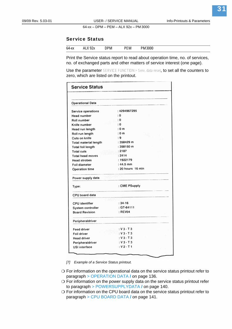
Print the Service status report to read about operation time, no. of services, no. of exchanged parts and other matters of service interest (one page).
Use the parameter SERVICE FUNCTION > Serv. data reset, to set all the counters to zero, which are listed on the printout.
[7] Example of a Service Status printout.
For information on the operational data on the service status printout refer to paragraph > OPERATION DATA / on page 136.For information on the power supply data on the service status printout refer to paragraph > POWERSUPPLYDATA / on page 140.For information on the CPU board data on the service status printout refer to paragraph > CPU BOARD DATA / on page 141.

09/09 Rev. 5.03-01 USER- / SERVICE MANUAL Info-Printouts & Parameters
64-xx – DPM – PEM – ALX 92x – PM 3000
32
For information on the peripheral driver data on the service status printout refer to paragraph > MODULE FW VERS. / on page 135.
Dottest endless
64-xx ALX 92x DPM PEM PM 3000
Dottest for application with endless label stock.
This function prints a pattern which enables trained personnel to check the adjustment as well as the function of the printhead.
Only in supervisor mode:
If no dot check has been proceeded (by calling the parameter SERVICE FUNCTION > Head dot test) since powering on the printer, a test is started before printing the status report. Depending on the result, one of the following messages is printed on the bottom margin of the label:
"All print dots o.k.""x print dots defective"
64-08 printers don´t proceed this dot check automatically, because this would be very time consuming. The printout shows the message:
"Head Dot Test not yet executed"
If a dot test has already been performed since powering on the printer, the above showed messages are also displayed at 64-08 printers after proceed-ing a "Dottest endless“ or „Dottest punched".
For information about the supervisor mode, refer to parameter SYSTEM PARAMETERS > Access authoriz..
Test pattern
The „Dottest endless“ or „Dottest punched“ prints a pattern consisting of 33 rows filled with vertical lines on the upper label area. All lines have a constant distance of 4 dot. With every new row, the line pattern is shifted one dot. The resulting line-pattern repeats every four rows.The test pattern shows missing dots clearly as white vertical lines running through the pattern.
The lower label area is filled with testpatterns, which are kept close to those used by Kyocera. The patterns are useful for printout comparison.
The bars underneath the test pattern allow the adjustment of the different zero lines.
Dottest punched
64-xx ALX 92x DPM PEM PM 3000
Dottest for application with punched material.
See parameter Dottest endless / on page 32.

09/09 Rev. 5.03-01 USER- / SERVICE MANUAL Info-Printouts & Parameters
64-xx – DPM – PEM – ALX 92x – PM 3000
33
Reference label
64-xx ALX 92x DPM PEM PM 3000
Prints a label with some examples of barcodes, fonts, logos... just try out!
[8] Example of a Reference label printout.

09/09 Rev. 5.03-01 USER- / SERVICE MANUAL Info-Printouts & Parameters
64-xx – DPM – PEM – ALX 92x – PM 3000
34
RFID StatusOnly with activated RFID option.
64-xx ALX 92x DPM PEM PM 3000
Prints a status printout with RFID specific data:
RFID Status
System version : V4.00Jun 23 2005[R4.00 PE2.50 H4.00Q]
Printer type : Avery 64-05
Nr CMD retries : 3
Nr invalid tags : 3
Statistics
Nr of Tags : 7043
Nr. invalid tags : 2788
Total Nr. SELECT : 7803
Invalid SELECT : 16%
Total Nr. READ : 1189
Invalid READ : 29%
Total Nr. WRITES : 5483
Invalid WRITE : 37%
Rate READ : 45
Rate WRITE : 46
[3] Beispiel eines Ausdrucks INFO AUSDRUCKEN > RFID Status.

09/09 Rev. 5.03-01 USER- / SERVICE MANUAL Info-Printouts & Parameters
64-xx – DPM – PEM – ALX 92x – PM 3000
35
PRINT PARAMETERS
Print speed
64-xx ALX 92x DPM PEM PM 3000
The print speed (material feed) can be adjusted according to the ribbon and material combination being used in order to optimise the contrast depth and the density of the print image.
x inch/s (mm/s) Setting range: see table; Unit interval: 1 inch/s (5 mm/s)Default setting: 8 inch/s
DPM and ALX 92x: Print speed can be set optionally in Inch/s or mm/s. The unit is selected with SYSTEM PARAMETERS > Speed unit.
x Inch/s Setting range: see table; Unit interval: 0,2 inch/s; Default setting: 8 Inch/s
Feed speed
64-xx ALX 92x DPM PEM PM 3000
The feed speed can be increased between print periods hereby reducing the total print time, particularly with long labels with a minimum printed surface.
Setting:The value for the feed speed should not be set too high for print applications with long calculating units (e. g. consecutive numbering). This can help to avoid alternating between abrupt braking to 0 (zero) and acceleration to print speed.
When altering the print speed, the feed speed is equal to the print speed. If a different feed speed is required, this must be set again.
x inch/s Setting range: 2 to 12 inch/s; Unit interval: 1 inch/sDefault setting: 8 inch/s
(only DPM / PEM / ALX 924)Machines of the DPM / PEM / ALX 924 type provide the option to change the displayed unit between Inch/s and mm/s.
Setting is done using the parameter SYSTEM PARAMETERS > Speed unit.x Inch/sx mm/s
Setting range: 2 to 12 inch/s or 51 to 305 mm/s;Unit interval: 0,2 inch/s or 5 mm/s; Default setting: 8 Inch/s
Printer Print speed in mm/s
Print speed in Inch/s
64-04/05 2-166406 2-1464-08 2-9ALX 924/925, DPM 4/5“, PEM 4/5“ 50-400 2-16ALX 926, DPM 6“, PEM 6“ 50-300 2-12
[4] The setting range of the print speed depends on the printer type.

09/09 Rev. 5.03-01 USER- / SERVICE MANUAL Info-Printouts & Parameters
64-xx – DPM – PEM – ALX 92x – PM 3000
36
Material type
64-xx ALX 92x DPM PEM PM 3000
Definition of the materials used. A distinction is made between reel material and gapped material (hole gaps, self-adhesive material with register gaps). The detected gap position corresponds to the start of the label.
The value is overwritten by the appropriate Easy Plug command when sending label formats.
Endless If material is to be used without gaps.
Punched If material is to be used with gaps (default setting).
Material length
64-xx ALX 92x DPM PEM PM 3000
The material length (label length) is the distance between the gaps, meas-ured from the front edge (beginning) of a label to the front edge of the next label.
The value is overwritten by the appropriate Easy Plug command when sending label formats.
xxx mm Setting range: 5 mm to "max. length entry"; Unit interval: 0.1 mmDefault setting: 100 mm
Maximum length entry: dependent on the print head width and memory con-figuration.
Material width
64-xx ALX 92x DPM PEM PM 3000
Zero position of the left border. If the printer is working in line-printer mode, alterations can be made in millimetre units.
xxx mm Setting range: "min. width" to "max. width"; Unit interval: 0.1 mmDefault setting: 100 mm
Min. width: dependent on the printer typeMax. width: dependent on print head width and memory configuration.
For detailed material width information, refer to topic section „Specifications“.

09/09 Rev. 5.03-01 USER- / SERVICE MANUAL Info-Printouts & Parameters
64-xx – DPM – PEM – ALX 92x – PM 3000
37
Print direction
64-xx ALX 92x DPM PEM PM 3000
[9] Orientation of the printout „Foot first“ (A) or „Head first“ (B).
Foot first (Default) Orientation of the printout according to [9A].
Head first Orientation of the printout according to [9B]. Mind the following:
Define the „true“ label length (without gap length) in parameter PRINT PARAMETERS > Material length. If the label gap is wider than 5 mm, the parameter SYSTEM PARAMETERS > Miss. label tol. must be set to a value more than zero.
The distance between material base line and the first printable dot is 1 mm. To keep this distance while printing „head first“, the material width must be calculated as follows::
, with
bMat: Material widthbBp: Backing paper width
A B
Printer
Printout
bMat bBp 2mm–=

09/09 Rev. 5.03-01 USER- / SERVICE MANUAL Info-Printouts & Parameters
64-xx – DPM – PEM – ALX 92x – PM 3000
38
Punch offset
64-xx ALX 92x DPM PEM PM 3000
The zero position can be determined offset in millimetre units from the detect-ed gap position.
The value is overwritten by the appropriate Easy Plug command when sending label formats.
xxx mm Setting range: -8 to +max. label length; Unit interval: 0,1mmDefault setting: 0 mm
Maximum offset in feed direction: -8 mm
Minimum offset against feed direction: +max. label length
[10] Positive and negative offset in relation to the feed direction (arrow).
Bar code multip.
64-xx ALX 92x DPM PEM PM 3000
Bar code height scaling factor
Increases the bar code height defined in the label layout (Easy-Plug) by multi-plication by a factor of 1 to 10.
x Setting range: 1 to 10; Unit interval: 1; Default setting: 1
The printed bar code height calculates starting with the value defined in the label layout multiplied by the scaling factor x.

09/09 Rev. 5.03-01 USER- / SERVICE MANUAL Info-Printouts & Parameters
64-xx – DPM – PEM – ALX 92x – PM 3000
39
Tradit. Imaging
64-xx ALX 92x DPM PEM PM 3000
In production mode only.
Up to firmware version x.31, the barcode height was calculated with the formula:
with x = PRINT PARAMETERS > Barcode Multi.
By doing so, the printed barcode height in millimeters was by 1 higher than the value defined in the layout (1 --> 2 mm, 2 --> 3 mm, etc.)1).
From firmware version x.31 on, the printed barcode is exactly as high in mil-limeters, as the value in the layout is (1 --> 1 mm, 2 --> 2 mm, etc.) 1).
No New height calculation (1 --> 1 mm, 2 --> 2 mm, etc.) is applied (default set-ting).The plain copy line is printed with OCR-B font.
Yes Setting for customers with print layouts based on the old height calculation scheme.The plain copy line of the barcodes EAN8, EAN13, UPC-A and UPC-E is prin-ted with the same fonts, which older printer types like TTK or TTX x50 have used.
UPC plain-copy
64-xx ALX 92x DPM PEM PM 3000
The position of the first and last digit in the plain-copy line - underneath the bar code - can be adjusted as required.
Raised First and last digit of the UPCA or first digit with the UPCE are raised (default setting).
In line All digits in the decoded line are in line under the code.
EAN Readline
64-xx ALX 92x DPM PEM PM 3000
<> Signs Readline enclosed in "<>" signs or terminated by a ">"-Sign (EAN 13).
Standard Readline without "<>" or ">" signs (default).
1) Assumed that PRINT PARAMETERS > Barcode Multi. = „1“.
BarcodehightPrint BarcodehightLayout 1+( ) x⋅=

09/09 Rev. 5.03-01 USER- / SERVICE MANUAL Info-Printouts & Parameters
64-xx – DPM – PEM – ALX 92x – PM 3000
40
EAN sep. lines
64-xx ALX 92x DPM PEM PM 3000
EAN separation lines. Parameter for controlling of EAN or UPC barcodes if they are printed without readline.
With readl. only (Default) The seperation bars at the beginning, end and in the middle of the barcode are only long, if the barcode is printed with a readline.
Always long The seperation bars at the beginning, end and in the middle of the barcode are always long, regardless if the barcode is printed with or without readline. The position of the barcode is the same as with the readline option switched on.
Rotated Barcodes
64-xx ALX 92x DPM PEM PM 3000
Improves the readability of rotated (90° and 270°) bar codes.
Normal „Normal“ printing without a special processing of rotated bar codes.
Optimized (Default setting) The line and gap widths of rotated bar codes are modified in order to improve their readability.
Dispense Mode
64-xx ALX 92x DPM PEM PM 3000
64-xx: Dispenser version only.
Governs the run of the print-dispense procedure.
The ribbon autoeconomy function can only be used in "Real 1:1 Mode"!
Dispense only With this setting, the printer can be used as a mere dispenser without processing print jobs. Set the material length before you use this function.
See parameter PRINT PARAMETERS > Material length.After calling "Dispense only", the printer restarts; afterwards, the following is displayed:
The parameters menu can be activated as usual after having switched to the offline mode by pressing the Online button two times.
Dispense onlyLabels 0
0 = Number of dispensed labels.

09/09 Rev. 5.03-01 USER- / SERVICE MANUAL Info-Printouts & Parameters
64-xx – DPM – PEM – ALX 92x – PM 3000
41
Normal 1:1 Mode The printer cannot print on the whole label surface. A stripe at the label beginning stays unprinted. The label is being dispensed while printing.The output volume is at its maximum level.
The width of the unprintable stripe is calculated as follows:Distance print line to dispensing edge + Dispense position (see [5])
Also refer to parameter PRINT PARAMETERS > Dispense position.A graphic can be found under PRINT PARAMETERS > Cut mode > Normal 1:1 mode.
[11] The size of the not imprintable area in Normal 1:1 depends of the setting of parameter "SYSTEM PARAMETERS/ Dispense Position".
Dispensing edge
Distance print line to dispensing edge
long 39.8 mmshort 24.2 mm
[5] A stripe of the width "distance print line to dispensing edge + dispense position" can not be printed in "Normal 1:1 Mode.
a b c
LabelBacking paper
Printing
Printhead
DispensingEdge
FeedDirection
Non-printable area with
DispenseDispense
a) Dispense position = 0b) position < 0c) position > 0
Z0
13
7E
.eps

09/09 Rev. 5.03-01 USER- / SERVICE MANUAL Info-Printouts & Parameters
64-xx – DPM – PEM – ALX 92x – PM 3000
42
Batch Mode The printer can print the whole label surface.Dispensing of the label takes place during printing. Printing of the next label is interrupted until the label is completely dispensed.The output volume is at its maximum level.
The Batch mode is optimised for printing and dispensing at high speeds. Due to this, it is not possible to use all features awaliable in modes Normal 1:1 or Real 1:1. Also consider, that printing data must be available on time and in sufficient quantity.
The following Job/Parameter-combinations must not be used:
Jobs with counter fieldsJobs with variable fieldsSYSTEM PARAMETER > Dispensing mode must be set to "fast".The USI reprint function is not supported. DP INTERFACE > Reprint signal must be set to "deactivated". Foil save
A graphic can be found under PRINT PARAMETERS > Cut mode > Batch mode.
Real 1:1 Mode (Default setting)The printer can print the whole label surface.After dispensing a label, the beginning of the next label is drawn back under the print head.The output volume is lower than in Batch Mode or Normal 1:1 Mode.
A graphic can be found under PRINT PARAMETERS > Cut mode > Real 1:1 mode.
Dispenseposition
64-xx ALX 92x DPM
64-xx: Dispenser version only.
Dispense position
Adjusts the dispense position in or against the feed direction. Depending on the set dispense position, the dispensed label sticks to the backing paper with a more or less wide strip (Fig. 11). The required width of this strip depends on the further processing.
[12] Dispense position (= stopp position) of the dispensed label.
x.x mm Setting range: -30.0 to +20.0 mm; Unit interval: 0,1 mm; Default setting: -6.0 mm
Dispensed label Dispense position
Dispensing edge
Backing paper
Z004
0E.c
dr

09/09 Rev. 5.03-01 USER- / SERVICE MANUAL Info-Printouts & Parameters
64-xx – DPM – PEM – ALX 92x – PM 3000
43
Cut mode
64-xx PM 3000
Only with mounted and activated cutter (SYSTEM PARAMETERS > Periph. device = „Cutter“).
This is where the procedure for the label output and cut is defined.
Real 1:1 mode The whole surface of the label is printable. The label is pushed forward to the cutter for cutting. After the cut, the beginning of the next label is drawn back under the print head. This reduces the output volume (in relation to a certain time).
[13] Printing process (schematic) in „Real 1:1 Mode“.
Avery
Avery
Avery
Avery
PrintheadCutter
1. Printing
2. Printing finished
3. Feeding
4. Cut andfeed back

09/09 Rev. 5.03-01 USER- / SERVICE MANUAL Info-Printouts & Parameters
64-xx – DPM – PEM – ALX 92x – PM 3000
44
Batch mode The whole surface of the label is printable. Cutting takes place during print-ing. This can result in brief interruptions within the print zone of the following label. The output volume is at its maximum level.
Requirements for the batch mode are:
Ribbon economy is not active (parameter SYSTEM PARAMETERS > Ribbon autoecon. = "Deactivated")Material length >18 mm (>14 mm on the TTX 350)Number of cuts for a print job - at least 2 or more
[14] Printing process in Batch mode (schematic).
Normal 1:1 mode In N1:1 mode, cutting takes place during printing. The zero-line of the printing is shifted 18 mm in y-direction. This offset equals the distance cutter-print-head. Caused by this shifting, the first 18 mm of the label are not printable. These measurement corresponds to the distance between print head and cutter. The output volume is at its maximum level.(The offset of the zero-line is caused historically and serves the compatibility of older printer models).
[15] Printing process in Normal 1:1 mode (schematic).
Avery
AveryAvery
Avery
Avery
Avery
PrintheadCutter
1. Printing
2. Stop printing +cut
3. Continueprinting
Avery
Avery
Avery
Avery
PrintheadCutter
1. Printing
2. PrintingEnd
3. Feeding
4. Cutting

09/09 Rev. 5.03-01 USER- / SERVICE MANUAL Info-Printouts & Parameters
64-xx – DPM – PEM – ALX 92x – PM 3000
45
Cut speed
64-xx
Only with mounted and activated cutter (SYSTEM PARAMETERS > Periph. device = „Cutter“).
The cut speed is to be adjusted to the material thickness and strength.
x inch/s Setting range: 2 to 5 inch/s; Unit interval: 1 inch/s
2 inch/s: extremely slow; for thick and strong material5 inch/s: extremely fast; for thin material
Cut position
64-xx
Only with mounted and activated cutter (SYSTEM PARAMETERS > Periph. device = „Cutter“).
The cut position is identical to the detected gap position, i. e. with the start of the label. Fine settings to meet specific customer requirements can be pro-grammed using the parameter PRINT PARAMETER > Cut position.
x inch/s Setting range: -2.0 to +2.0 mm; Unit interval: 0.1mm
Maximum offset in feed direction: -2.0 mmNo offset: 0 mmMinimum offset against feed direction: -2.0 mm
Double cut
64-xx
Only with mounted and activated cutter (SYSTEM PARAMETERS > Periph. device = „Cutter“).
Joining grids or the gap area between the labels can be removed using a double cut, thereby improving the outline.
The first cut is offset by the distance set from the recognized gap position away in the feed direction, the second cut is made at the gap position.
A possible correction of the cut position ("Cut position" function) is calculat-ed for both cuts and must be taken into consideration.
x inch/s Setting range: 0.0 to 5.0 mm; Unit interval: 0.1mm
Normal simple cut: 0.0 mm
The smallest possible double cut distance of 1.0 mm must be adhered to!

09/09 Rev. 5.03-01 USER- / SERVICE MANUAL Info-Printouts & Parameters
64-xx – DPM – PEM – ALX 92x – PM 3000
46
Rewind direction
64-xx
Only with mounted and activated rewinder (SYSTEM PARAMETERS > Periph. device = „Rewinder“).
Determines the sense of rotation of the optional Rewinder.
Printing outside Rewind direction: The printed label is facing outside.
Printing inside Rewind direction: The printed label is facing inside.
X - Printadjust
64-xx ALX 92x DPM PEM PM 3000
The zero point of the mask is moved in relation to the edge of the label on the X- axis, i. e. lengthways to the material.
If the setting is changed, while the print job is stopped, the printer recalculates the format using the changed values.
Caution with graphics, which are generated via one of the Easy Plug commands #YI, #YIR or #YIB! If the graphics is shifted beyond the label border as a consequence of changing the parameter "X-Printadjust", the part of the graphics which "juts out" will get lost.
x.x mm Setting range: -5.0 to +5.0 mm; Unit interval: 0.1mmDefault setting: 0.0 mm
Maximum offset away from the edge of the label: +5.0 mmNo offset: 0.0mmMaximum offset towards the edge of the label: -5.0 mm
Y – Printadjust
64-xx ALX 92x DPM PEM PM 3000
The zero point of the mask is moved in relation to the gap position on the Y-axis, i. e. in the feed direction.
If the setting is changed, while the print job is stopped, the printer recalculates the format using the changed values.
Caution with graphics, which are generated via one of the Easy Plug commands #YI, #YIR or #YIB! If the graphics is shifted beyond the label border as a consequence of changing the parameter "Y-Printadjust", the part of the graphics which "juts out" will get lost.
x.x mm Setting range: -5.0 to +5.0 mm; Unit interval: 0.1mmDefault setting: 0.0 mm
Maximum offset in feed direction: +5.0 mmNo offset: 0.0mmMinimum offset against feed direction: -5.0 mm

09/09 Rev. 5.03-01 USER- / SERVICE MANUAL Info-Printouts & Parameters
64-xx – DPM – PEM – ALX 92x – PM 3000
47
Punch mode
64-xx ALX 92x DPM PEM PM 3000
Automatic Automatic mode, for material with a contrast zone = gap in the label.
"Automatic" is the default setting, suitable for all materials with which there is a difference in the transparency between the label and gap of more than 2 values (see Description, sensor check).
Manual Manual setting, for material with several varying contrast zones. Settings are made using the parameter PRINT PARAMETER > Punch level.
The range of the value automatically measured by the gap detection can be defined specifically for the label material. This allows materials with high-con-trast proof points within the label to be processed, which would otherwise be measured as 'false' gaps by the system. The corresponding setting value is then equal to, or smaller than, the value measured at the actual gap.
Punch level
64-xx ALX 92x DPM PEM PM 3000
Only if PRINT PARAMETERS > Punch mode = „Manual“.
xxx Setting range: 0 to 255; Unit interval: 1
The value xxx stands for the current contrast within the photoelectric switch of the material which has just been inserted. This serves to determine a threshold value for the inserted material.
xxx = current measurement at the punch sensoryyy = set threshold value
Example
Self-adhesive material with black bars lengthways across the label
Reading:– Masking paper: 30– Masking paper + label: 60– Masking paper + label + black bars: 190
Setting value: 60A setting value of 60 means that all readings over 60 are ignored, therefore also the reading 190 at the black bar.
PunchlevelPunch xxx Val yyy

09/09 Rev. 5.03-01 USER- / SERVICE MANUAL Info-Printouts & Parameters
64-xx – DPM – PEM – ALX 92x – PM 3000
48
INTERFACE PARAInterface parameter
> EASYPLUGINTERPR
Interface
64-xx ALX 92x DPM PEM PM 3000
Interface type
This parameter sets the interface, by which the printer will receive data.
Serial Com1 Serial interface Com1.
Selection of the type of serial interface is done with parameter INTERF. PARAM > EASYPLUGINTERPR > Serial Port Mode.
Serial Com2 Serial interface Com2.
Only with optional I/O board mounted.
Mounting the I/O board changes the parameter SERVICE FUNCTION > Easy Plug Monitor: The monitor data will be transmitted via Com1.
Centronics Parallel interface (Centronics); Default setting
Only for Ethernet interface (10/100 Base T):
TCP/IP Socket Print data can be sent to the printer via a TCP/IP socket
LPD Server Print data can be sent to the printer via the LPR/LPD-protocol
Automatic All interfaces are enabled to receive data, but not simultaneously.
Don´t send data to more than one interface at a time.
Except are interfaces, which are being used by an option (e.g. OLV).
Spooler mode
64-xx ALX 92x DPM PEM PM 3000
The operating mode of the spooler determines whether print series are proc-essed individually, or whether the spooler can receive print data when print-ing several series.
Single print job Single print series mode (the interface can only receive data after printing the required number of labels of a single series)
Mult. print jobs Multiple print series mode (the interface can receive data while the series is being printed)

09/09 Rev. 5.03-01 USER- / SERVICE MANUAL Info-Printouts & Parameters
64-xx – DPM – PEM – ALX 92x – PM 3000
49
Printer ID No.
64-xx ALX 92x DPM PEM PM 3000
Printer identification number
Determines the identification number of the printer. In such a way, the printer can be addressed by the Easy Plug command #!An (n=printer ID).
The use of ID numbers is in particular reasonable for data transfer by RS422/485 interface, if several printers are connected by one data line. Each of the connected printers then only incorporates the data mapped to him by #!An command.
xx Setting range: 0 to 31; Unit interval: 1
Spooler size
64-xx ALX 92x DPM PEM PM 3000
The memory capacity of the printer buffer can be set according to the require-ments of each customer.
xxx Kbyte Setting ranges:– 64-xx Gen. 3: 16 to 2048 KBytes– Other devices: 16 to 256 KBytes
Unit interval: 16 KBytes; default setting: 64 kBytes
CAUTION! - All data present in the printer buffer is deleted when altering the spooler size!
The maximum print format is influenced by the spooler size if no plug-in card is used for memory expansion.
Offline mode
64-xx ALX 92x DPM PEM PM 3000
Interf. disabled Easy-Plug commands are not accepted, while the machine is in offline mode (default setting).
Interf. enabled Easy-Plug commands are accepted in offline mode.
Interface delay
64-xx ALX 92x DPM PEM PM 3000
After switching from online to offline mode, the printer interface is deactivat-ed. This parameter offers a setable delay time before deactivating the inter-face.
xxxx ms Setting range: 0-1000; Unit interval: 100; Default setting: 0
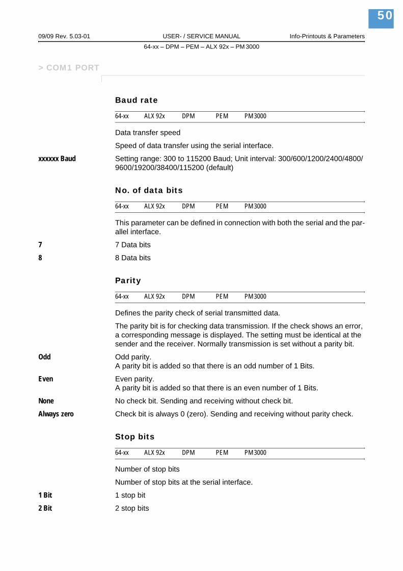
09/09 Rev. 5.03-01 USER- / SERVICE MANUAL Info-Printouts & Parameters
64-xx – DPM – PEM – ALX 92x – PM 3000
50
> COM1 PORT
Baud rate
64-xx ALX 92x DPM PEM PM 3000
Data transfer speed
Speed of data transfer using the serial interface.
xxxxxx Baud Setting range: 300 to 115200 Baud; Unit interval: 300/600/1200/2400/4800/9600/19200/38400/115200 (default)
No. of data bits
64-xx ALX 92x DPM PEM PM 3000
This parameter can be defined in connection with both the serial and the par-allel interface.
7 7 Data bits
8 8 Data bits
Parity
64-xx ALX 92x DPM PEM PM 3000
Defines the parity check of serial transmitted data.
The parity bit is for checking data transmission. If the check shows an error, a corresponding message is displayed. The setting must be identical at the sender and the receiver. Normally transmission is set without a parity bit.
Odd Odd parity. A parity bit is added so that there is an odd number of 1 Bits.
Even Even parity. A parity bit is added so that there is an even number of 1 Bits.
None No check bit. Sending and receiving without check bit.
Always zero Check bit is always 0 (zero). Sending and receiving without parity check.
Stop bits
64-xx ALX 92x DPM PEM PM 3000
Number of stop bits
Number of stop bits at the serial interface.
1 Bit 1 stop bit
2 Bit 2 stop bits

09/09 Rev. 5.03-01 USER- / SERVICE MANUAL Info-Printouts & Parameters
64-xx – DPM – PEM – ALX 92x – PM 3000
51
Data synch.
64-xx ALX 92x DPM PEM PM 3000
Data synchronisation at the serial interface.
RTS/CTS Data synchronisation through hardware
XON/XOFF Data synchronisation through software
None Handshake signals are ignored
Frame error
64-xx ALX 92x DPM PEM PM 3000
Display (Default) An error message is displayed, if a framing error is detected while the printer is receiving serial data.
Ignore Framing errors will be ignored, no error messages are displayed.
> COM2 PORT
This menu only appears, if the optional I/O board is installed.
Baud rate
64-xx ALX 92x DPM PEM
With mounted and connected I/O board only.
See parameter Baud rate / on page 53.
No. of data bits
64-xx ALX 92x DPM PEM
With mounted and connected I/O board only.
See parameter No. of data bits / on page 53.
Parity
64-xx ALX 92x DPM PEM
With mounted and connected I/O board only.
See parameter Parity / on page 53.

09/09 Rev. 5.03-01 USER- / SERVICE MANUAL Info-Printouts & Parameters
64-xx – DPM – PEM – ALX 92x – PM 3000
52
Stop bits
64-xx ALX 92x DPM PEM
With mounted and connected I/O board only.
See parameter Stop bits / on page 53.
Data synch.
64-xx ALX 92x DPM PEM
With mounted and connected I/O board only.
See parameter Data synch. / on page 54.
Serial Port Mode
64-xx ALX 92x DPM PEM
With mounted and connected I/O board only.
Setting of the serial interface type.
RS232 Sets Com2 to RS 232.Data synchronisation may be done by hardware (RTS/CTS) or by software (XON/XOFF). Maximum cable length is 15 m.
RS422 Sets Com2 to RS 422.RS 422 is a 4 wire point to point connection, suitable for only one device. Receiver and driver of the printer are always enabled. Data synchronization is only possible by software (XON/XOFF). Maximum cable length is 1 km with twisted telecommunication cable.
RS485 Sets Com2 to RS 485.RS 485 is a 2 or 4 wire bus system for up to 30 devices. The printer´s receiver is always enabled, the printer´s driver is only enabled, if the printer sends data to the host. Data synchronization is only possible by software (XON/XOFF). Maximum cable length is 1 km with twisted telecommunication cable.
Frame error
64-xx ALX 92x DPM PEM PM 3000
With mounted and connected I/O board only.
See parameter Frame error / on page 54.
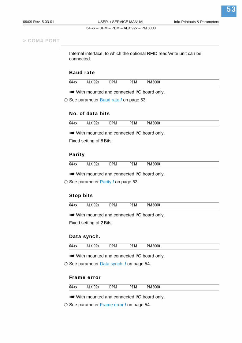
09/09 Rev. 5.03-01 USER- / SERVICE MANUAL Info-Printouts & Parameters
64-xx – DPM – PEM – ALX 92x – PM 3000
53
> COM4 PORT
Internal interface, to which the optional RFID read/write unit can be connected.
Baud rate
64-xx ALX 92x DPM PEM PM 3000
With mounted and connected I/O board only.
See parameter Baud rate / on page 53.
No. of data bits
64-xx ALX 92x DPM PEM PM 3000
With mounted and connected I/O board only.
Fixed setting of 8 Bits.
Parity
64-xx ALX 92x DPM PEM PM 3000
With mounted and connected I/O board only.
See parameter Parity / on page 53.
Stop bits
64-xx ALX 92x DPM PEM PM 3000
With mounted and connected I/O board only.
Fixed setting of 2 Bits.
Data synch.
64-xx ALX 92x DPM PEM PM 3000
With mounted and connected I/O board only.
See parameter Data synch. / on page 54.
Frame error
64-xx ALX 92x DPM PEM PM 3000
With mounted and connected I/O board only.
See parameter Frame error / on page 54.

09/09 Rev. 5.03-01 USER- / SERVICE MANUAL Info-Printouts & Parameters
64-xx – DPM – PEM – ALX 92x – PM 3000
54
> CENTRONICS
PnP function
64-xx ALX 92x DPM PEM PM 3000
Off The printer doesn´t send any identification signals to the Centronics port.
On The printer sends identification signals via the Centronics port (if any is connected) to the host computers Windows operating system. Windows will search for an appropriate driver. (Default setting).
> NETWORK PARAM.
IP addressassign
64-xx ALX 92x DPM PEM PM 3000
A change of this parameter setting forces a printer restart.
Fixed IP address This setting activates the parameters "Net mask" and "Gateway address" (see below).
DHCP IP address is assigned automatically. The assigned IP address is displayed for a moment on the printer display, while the printer is starting.
IP address
64-xx ALX 92x DPM PEM PM 3000
xxx.xxx.xxx.xxx Setting range per xxx value: 0 to 255
Change between the digits by pressing the Cut or Feed button; Acknowledge the setting by pressing the Online button. After a change of the IP address, the printer will reset automatically.
Net mask
64-xx ALX 92x DPM PEM PM 3000
xxx.xxx.xxx.xxx Setting range per xxx value: 0 to 255
Depending on the set IP address appears a default value.
We recommend to use the default value!

09/09 Rev. 5.03-01 USER- / SERVICE MANUAL Info-Printouts & Parameters
64-xx – DPM – PEM – ALX 92x – PM 3000
55
Gateway address
64-xx ALX 92x DPM PEM PM 3000
xxx.xxx.xxx.xxx Setting range per xxx value: 0 to 255
000.000.000.000 = no gateway is used
Port address
64-xx ALX 92x DPM PEM PM 3000
Setting range: 1024 to 65535. Default: 9100.
Ethernet speed
64-xx ALX 92x DPM PEM PM 3000
Auto negotioation The communication speed is selected automatically.
10M half duplex The communication speed is set to 10 MBit/s half duplex.
10M full duplex The communication speed is set to 10 MBit/s full duplex.
100M half duplex The communication speed is set to 100 MBit/s half duplex.
100M full duplex The communication speed is set to 100 MBit/s full duplex.
MAC address
64-xx ALX 92x DPM PEM PM 3000
Displays the MAC address of the CPU board. This address can not be changed in the parameter menu.
SNMP agent
64-xx ALX 92x DPM PEM PM 3000
Function is not released yet.
SNMP password
64-xx ALX 92x DPM PEM PM 3000
Only in production mode.
Function is not released yet.

09/09 Rev. 5.03-01 USER- / SERVICE MANUAL Info-Printouts & Parameters
64-xx – DPM – PEM – ALX 92x – PM 3000
56
FTP server
64-xx ALX 92x DPM PEM PM 3000
The File Transfer Protocol (FTP) server (RFC959) allows access to the RAM disk inside of the printer and, if available, to the CompactFlash-card. The FTP server is capable of multisession mode, without evaluating the user name when logging in. The password must match the set password (see below).
The FTP server can be used with the following clients:
GNU Midnight Commander 4.6.0 (OS: Linux)WS-FTP Pro 5.0 (OS: Windows NT/95)MS-IE 5.0, 5.5, 6.0 (OS: Windows NT/95)
Enabled Switches the FTP server on.
Disabled Switches the FTP server off.
FTP password
64-xx ALX 92x DPM PEM PM 3000
Input of the FTP server password by means of a connected keyboard or the printers operation panel. Default setting: „avery“.
Changing the password:
1. Press the Esc button. The cursor jumps to the first character.
2. Press the Cut- or Feed button until the wanted character appears. Acknowledge by pressing the Online button.
3. Put in the next character.
4. Acknowledge the new password by pressing the Online button.
If a keyboard is connected, this can be used for typing in the password.
Folder structure CommentCF This folder is only visible with a CF-card inserted.
FONTS Folder for font files on CF-cardFORMATS Folder for print job files on CF-cardGRAPHICS Folder for graphic files on CF-cardLOGOS Folder for logo files on CF-card
FONTS Folder for font files on the internal RAM diskGRAPHICS Folder for graphic files on the internal RAM diskLOGOS Folder for logo files on the internal RAM disk
[6] This folder structure is visible in the FTP client window, if a CF-card is inserted into the printer card slot.

09/09 Rev. 5.03-01 USER- / SERVICE MANUAL Info-Printouts & Parameters
64-xx – DPM – PEM – ALX 92x – PM 3000
57
WEB server
64-xx ALX 92x DPM PEM PM 3000
The web server may be used to
read out or change parameter settings of the printer into a web browserOperate the printer via a web browser.
Requirements for use of the web server function:
Printer is connected to networkA valid IP address is assigned to the printer (by the network administrator or by a DHCP server)INTERFACE PARA > NETWORK PARAM. > WEB server must be set to „Enabled“.
Starting the web server:
1. Write down the printers IP address (INTERFACE PARA > NETWORK PARAM. > IP address).
2. Start the web browser.
Insert into the address field: http://[IP address without leading zeros]Example: IP address = 144.093.029.031Input: http://144.93.29.31
3. Click „Login“.
4. Type in user name (admin) and password (admin).
If the login was successful, you will find the following menu items at the left window margin:
Enabled Switches the web server on.
Disabled Switches the web server off.
Menu item FunctionHome Jump to the home pageLogout Interrupt the connection to the printerParameter Opens the parameter menu. By clicking on submenus and pa-
rameters, those can be opened and the parameter setttings be changed.
Some parameters force the printer to reset, if their setting is modified by means of the operation panel. If the parameters are changed via the web server, this doesn´t happen automatically. Therefore, the modifications only become effective after the next printer restart. A restart can be triggered remote in the „Display view“.
Display view Opens the display operation panel. Enables remote operation of the printer.
Download Opens another browser window with the URL of the FTP ser-ver. For more information read the description of INTERFACE PARA > NETWORK PARAM. > FTP server.
Help Help texts
[7] Functions of the web server.

09/09 Rev. 5.03-01 USER- / SERVICE MANUAL Info-Printouts & Parameters
64-xx – DPM – PEM – ALX 92x – PM 3000
58
WEB display refrWEB display refresh
64-xx ALX 92x DPM PEM PM 3000
Automatic updating of the web browser display. The setting determines the time in seconds between two updates.
Setting 0 = „no automatic updating“.
xx s Setting range: 0 to 20; Default setting: 5
WEB admin passw.WEB administrator password
64-xx ALX 92x DPM PEM PM 3000
Only in production mode.
Modifying the password for web server access as admin.Default setting: „admin“
The user name is also „admin“.
If the user logs in as admin to the web server, he/she has access to all parameters, which are not marked with the footmark „only in production mode“.
Changing the password at the operating panel:
1. Press the Esc button. The cursor jumps to the first character.
2. Press the Cut- or Feed button until the wanted character appears. Acknowledge by pressing the Online button.
3. Type in the next character.
4. Acknowledge the new password by pressing the Online button.
Alternatively, the password can be typed in using a keyboard, or via the web server.
WEB supervisor p.WEB supervisor password
64-xx ALX 92x DPM PEM PM 3000
Only in production mode.
Modifying the password for web server access as supervisor.Default setting: „supervisor“
The user name is also „supervisor“.
If the user logs in as supervisor to the web server, he/she has access to all parameters.
Changing the password at the operating panel:

09/09 Rev. 5.03-01 USER- / SERVICE MANUAL Info-Printouts & Parameters
64-xx – DPM – PEM – ALX 92x – PM 3000
59
1. Press the Esc button. The cursor jumps to the first character.
2. Press the Cut- or Feed button until the wanted character appears. Acknowledge by pressing the Online button.
3. Type in the next character.
4. Acknowledge the new password by pressing the Online button.
Alternatively, the password can be typed in using a keyboard, or via the web server.
Time client
64-xx ALX 92x DPM PEM PM 3000
Loads the current time from a time server.
Disabled The time client is switched off.
Enabled The time client is switched on. The time is loaded with the frequency set un-der Sync. interval from a time server with the IP address Time server IP.
With the time client service, the current date and time can be obtained from a time server using RFC868 time protocol on UDP port 37. For this purpose, a time server IP address needs to be given. Date and
time are initially requested at start up an optional in a setable update interval during operation time. It is also stored in the internal real time clock. There is no time offset or daylight saving hour, so the server time must exactly match the local time of the printer.
Time server IP
64-xx ALX 92x DPM PEM PM 3000
IP address of the time server.
Only appears if INTERFACE PARA > NETWORK PARAM. > Time client = „Enabled“.
xxx.xxx.xxx.xxx Enter the IP address following the xxx.xxx.xxx.xxx schema.Setting range for each xxx value: [0…255].
Sync. Interval
64-xx ALX 92x DPM PEM PM 3000
Determines the frequency for time requests.
Only appears if INTERFACE PARA > NETWORK PARAM. > Time client = „Enabled“.
xxxx Setting range: [0…9999] s; Default setting: 3600 s.

09/09 Rev. 5.03-01 USER- / SERVICE MANUAL Info-Printouts & Parameters
64-xx – DPM – PEM – ALX 92x – PM 3000
60
DHCP host name
64-xx ALX 92x DPM PEM PM 3000
Host name of the printer. Default setting: „Device name“ + the last 3 figures of the MAC adress.
Typing in the host name at the operating panel:
1. Press the Esc button. The cursor jumps to the first character.
2. Press the Cut- or Feed button until the wanted character appears. Acknowledge by pressing the Online button.
Valid characters: A-Z, a-z, 0-9, -
3. Type in the next character.
4. Acknowledge the new password by pressing the Online button.
Alternatively, the password can be typed in using a keyboard, or via the web server.
WLAN SSID
64-xx ALX 92x DPM PEM PM 3000
Only with plugged-in WLAN CF-card
A Service Set Identifier (SSID) is the identification of a radio frequency net-work, which is based on IEEE 802.11.
Each WLAN owns a configurable SSID, by which the network is identified. The SSID is the name of the network.
The SSID character string is configured in the base station (Access Point) of the WLAN. It must be also configured on all clients, which are supposed to access the access point. The SSID is attached uncoded to all pakkets to identify them as part of that network.
xxxxxxxxxxx… The SSID consists of a maximum of 32 alphanumeric characters. Default set-ting: „avery“
Detailed information about using the WLAN feature: read the user manual, topic section Advanced Applications .
WLAN WEP
64-xx ALX 92x DPM PEM PM 3000
Only with plugged-in WLAN CF-card
WEP („Wired Equivalent Privacy“) is an encryption scheme for WLAN.
Disabled (Default setting) Communication with the host is not encoded.
64Bit key Communication with the host is encoded using 64 Bit WEP encoding.
128Bit key Communication with the host is encoded using 128 Bit WEP encoding.

09/09 Rev. 5.03-01 USER- / SERVICE MANUAL Info-Printouts & Parameters
64-xx – DPM – PEM – ALX 92x – PM 3000
61
Detailed information about using the WLAN feature: read the user manual, topic section Advanced Applications .
WLAN default key
64-xx ALX 92x DPM PEM PM 3000
Only with plugged-in WLAN CF-card
Selection of the encryption key, which is used for packet transmission.
x Setting range: 1-4; Default setting: 1
Detailed information about using the WLAN feature: read the user manual, topic section Advanced Applications .
WLAN 64Bit key 1
64-xx ALX 92x DPM PEM PM 3000
Only with plugged-in WLAN CF-card
Definition of an encryptioin key for pakket transmission. The key will be used, if it is enabled under INTERFACE PARA > NETWORK PARAM. > WLAN default key.
xxxxxxxxxxx… Character string of 26 hexadecimal characters. Default setting: „123456789abcd123456789abcd“
Admissible characters: A-Z, a-z, 0-9
Detailed information about using the WLAN feature: read the user manual, topic section Advanced Applications .
WLAN 64Bit key 2
64-xx ALX 92x DPM PEM PM 3000
Only with plugged-in WLAN CF-card
See parameter WLAN 64Bit key 1 / on page 64.
WLAN 64Bit key 3
64-xx ALX 92x DPM PEM PM 3000
Only with plugged-in WLAN CF-card
See parameter WLAN 64Bit key 1 / on page 64.
WLAN 64Bit key 4
64-xx ALX 92x DPM PEM PM 3000
Only with plugged-in WLAN CF-card
See parameter WLAN 64Bit key 1 / on page 64.

09/09 Rev. 5.03-01 USER- / SERVICE MANUAL Info-Printouts & Parameters
64-xx – DPM – PEM – ALX 92x – PM 3000
62
WLAN 128Bit key 1
64-xx ALX 92x DPM PEM PM 3000
Only with plugged-in WLAN CF-card
Definition of an encryptioin key for pakket transmission. The key will be used, if it is enabled under INTERFACE PARA > NETWORK PARAM. > WLAN default key.
xxxxxxxxxxx… Character string of 26 hexadecimal characters. Default setting: „123456789abcd123456789abcd“
Admissible characters: A-Z, a-z, 0-9
Detailed information about using the WLAN feature: read the user manual, topic section Advanced Applications .
WLAN 128Bit key 2
64-xx ALX 92x DPM PEM PM 3000
Only with plugged-in WLAN CF-card
See parameter WLAN 128Bit key 1 / on page 65.
WLAN 128Bit key 3
64-xx ALX 92x DPM PEM PM 3000
Only with plugged-in WLAN CF-card
See parameter WLAN 128Bit key 1 / on page 65.
WLAN 128Bit key 4
64-xx ALX 92x DPM PEM PM 3000
Only with plugged-in WLAN CF-card
See parameter WLAN 128Bit key 1 / on page 65.
WLAN com quality
64-xx ALX 92x DPM PEM PM 3000
Only with plugged-in WLAN CF-card
This value represents the signal-to-noise ratio (SNR) of the connection. The value is shown in % and is a measure for the connection quality.
x% WLAN communication quality in %
Detailed information about using the WLAN feature: read the user manual, topic section Advanced Applications .

09/09 Rev. 5.03-01 USER- / SERVICE MANUAL Info-Printouts & Parameters
64-xx – DPM – PEM – ALX 92x – PM 3000
63
WLAN signal lev.
64-xx ALX 92x DPM PEM PM 3000
Only with plugged-in WLAN CF-card
Shows the WLAN average signal level in percent. This value suits for optimiz-ing the location of the printer or access point to get the best network connec-tion.
x% Signal level in %
Detailed information about using the WLAN feature: read the user manual, topic section Advanced Applications .
> OPTIONS
Remote Display
64-xx ALX 92x DPM PEM PM 3000
Parameter only for development use. Enables controlling the operation panel via serial interface, e.g. with a PC.
This parameter has nothing to do with the optional available remote display, which is connected to a separate outlet.
For details about installing the remote display option, see service manual of the printer, topic section „Service Mechanics“, chapter „Assembling accesso-ries“.
Disabled Remote display is not activated.
Serial Com1 The Remote display is connected to Com1.This setting option is only visible, if no other option is activated at Com1.
Serial Com2 The Remote display is connected to Com2.This setting option is only visible, if no other option is activated at Com2.
OLV Option
64-xx ALX 92x DPM PEM PM 3000
Disabled OLV-Option is not activated (OLV = Online Verifier).
Serial Com1 The OLV is connected to Com1.This setting option is only visible, if no other option is activated at Com1.
Serial Com2 The OLV is connected to Com2.This setting option is only visible, if no other option is activated at Com2.
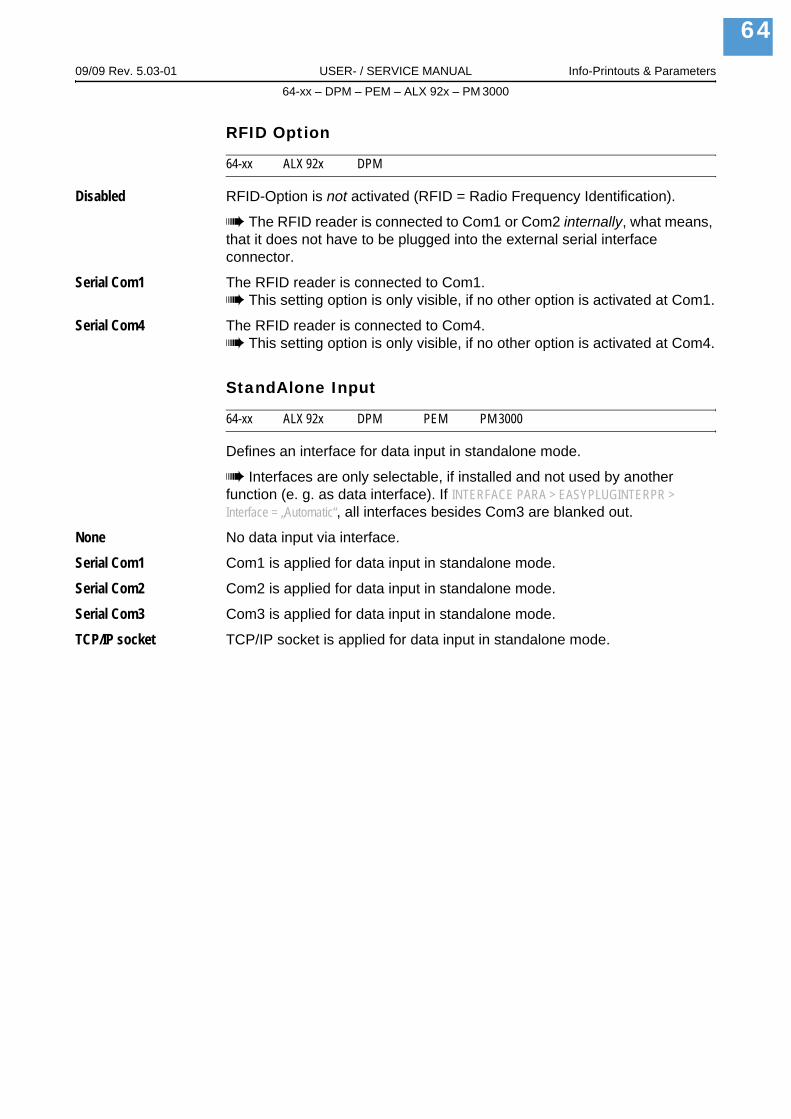
09/09 Rev. 5.03-01 USER- / SERVICE MANUAL Info-Printouts & Parameters
64-xx – DPM – PEM – ALX 92x – PM 3000
64
RFID Option
64-xx ALX 92x DPM
Disabled RFID-Option is not activated (RFID = Radio Frequency Identification).
The RFID reader is connected to Com1 or Com2 internally, what means, that it does not have to be plugged into the external serial interface connector.
Serial Com1 The RFID reader is connected to Com1.This setting option is only visible, if no other option is activated at Com1.
Serial Com4 The RFID reader is connected to Com4.This setting option is only visible, if no other option is activated at Com4.
StandAlone Input
64-xx ALX 92x DPM PEM PM 3000
Defines an interface for data input in standalone mode.
Interfaces are only selectable, if installed and not used by another function (e. g. as data interface). If INTERFACE PARA > EASYPLUGINTERPR > Interface = „Automatic“, all interfaces besides Com3 are blanked out.
None No data input via interface.
Serial Com1 Com1 is applied for data input in standalone mode.
Serial Com2 Com2 is applied for data input in standalone mode.
Serial Com3 Com3 is applied for data input in standalone mode.
TCP/IP socket TCP/IP socket is applied for data input in standalone mode.
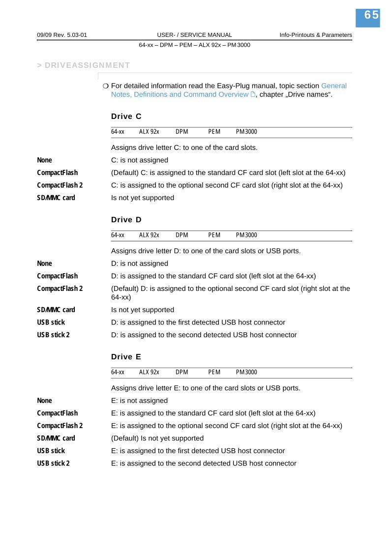
09/09 Rev. 5.03-01 USER- / SERVICE MANUAL Info-Printouts & Parameters
64-xx – DPM – PEM – ALX 92x – PM 3000
65
> DRIVEASSIGNMENT
For detailed information read the Easy-Plug manual, topic section General Notes, Definitions and Command Overview , chapter „Drive names“.
Drive C
64-xx ALX 92x DPM PEM PM 3000
Assigns drive letter C: to one of the card slots.
None C: is not assigned
CompactFlash (Default) C: is assigned to the standard CF card slot (left slot at the 64-xx)
CompactFlash 2 C: is assigned to the optional second CF card slot (right slot at the 64-xx)
SD/MMC card Is not yet supported
Drive D
64-xx ALX 92x DPM PEM PM 3000
Assigns drive letter D: to one of the card slots or USB ports.
None D: is not assigned
CompactFlash D: is assigned to the standard CF card slot (left slot at the 64-xx)
CompactFlash 2 (Default) D: is assigned to the optional second CF card slot (right slot at the 64-xx)
SD/MMC card Is not yet supported
USB stick D: is assigned to the first detected USB host connector
USB stick 2 D: is assigned to the second detected USB host connector
Drive E
64-xx ALX 92x DPM PEM PM 3000
Assigns drive letter E: to one of the card slots or USB ports.
None E: is not assigned
CompactFlash E: is assigned to the standard CF card slot (left slot at the 64-xx)
CompactFlash 2 E: is assigned to the optional second CF card slot (right slot at the 64-xx)
SD/MMC card (Default) Is not yet supported
USB stick E: is assigned to the first detected USB host connector
USB stick 2 E: is assigned to the second detected USB host connector

09/09 Rev. 5.03-01 USER- / SERVICE MANUAL Info-Printouts & Parameters
64-xx – DPM – PEM – ALX 92x – PM 3000
66
Drive F
64-xx ALX 92x DPM PEM PM 3000
Assigns drive letter F: to one of the card slots or USB ports.
None F: is not assigned
CompactFlash F: is assigned to the standard CF card slot (left slot at the 64-xx)
CompactFlash 2 F: is assigned to the optional second CF card slot (right slot at the 64-xx)
SD/MMC card Is not yet supported
USB stick (Default) F: is assigned to the first detected USB host connector
USB stick 2 F: is assigned to the second detected USB host connector
Drive G
64-xx ALX 92x DPM PEM PM 3000
Assigns drive letter G: to one of the card slots or USB ports.
None (Default) G: is not assigned
CompactFlash G: is assigned to the standard CF card slot (left slot at the 64-xx)
CompactFlash 2 G: is assigned to the optional second CF card slot (right slot at the 64-xx)
SD/MMC card Is not yet supported
USB stick G: is assigned to the first detected USB host connector
USB stick 2 G: is assigned to the second detected USB host connector

09/09 Rev. 5.03-01 USER- / SERVICE MANUAL Info-Printouts & Parameters
64-xx – DPM – PEM – ALX 92x – PM 3000
67
SYSTEM PARAMETERS
Head disp dist.
64-xx ALX 92x DPM PEM
64-xx: 64-xx dispenser only and only with SYSTEM PARAMETER > Dispensing edge = „User defined“
For setting the distance between printhead and dispensing edge.
xxx.x mm Setting range: 10.0 to 100.0 mm; Unit interval: 0.1 mm;Default setting: 20 mm
Speed unit
ALX 92x DPM PEM
The print or feed speed can optional be set in mm/s or in inch/s.
mm/s Set speeds in mm/s
Inch/s Set speeds in inch/s (default)
Cover open error
PM 3000
Defines, when the status message „Cover open“ appears:
Immediately Status message appears immediately after opening the hood (default).
If material feed Statusmessage appears if the hood is open and material feed is supposed to start.
Printstatus: 5003Cover open

09/09 Rev. 5.03-01 USER- / SERVICE MANUAL Info-Printouts & Parameters
64-xx – DPM – PEM – ALX 92x – PM 3000
68
Foil end warning
64-xx ALX 92x DPM PEM PM 3000
Setting of a limit diameter for the ribbon roll. If the ribbon roll diameter falls below the set value, the displayed message changes from…
64-xx, DPM / PEM, ALX 92x:Additionally to the display message, a signal is set at the (optional) USI.
For details refer to the parameters DP INTERFACE > Ribbon signal and SERVICE DATA > OPERATION DATA > Foil diameter
x.xx mm Setting range: 25.4 to 50.0 mm; Unit interval: 0.1 mm;Default setting: 25.4 mm
Foil warn stop
64-xx ALX 92x DPM PEM PM 3000
Disabled (Default setting) Printer does not stop in case of a „Foil end warning“.
Enabled If a „Foil end warning“ occurs, the printer stops after the current label and shows the status message:
Press the online button to acknowledge the message, then the feed button to continue printing.
Display mode
64-xx ALX 92x DPM PEM PM 3000
64-xx: Dispenser version only.
Makes the already printed labels appear in the display instead of the not yet printed ones.
Job rest quant. Display of the not yet printed labels of a print job.
The counter keeps it´s value even after switching the printer off.
Dispense counter Counting of start pulses. Activate the counter by selecting "Dispense coun-ter". The counted number appears on the display after the parameter Dispense counter (see below) has been selected.
ONLINE X JOBS …to…
FOLIE X JOBS …while the display is blinking.
PrintStatus: 5110Foil low

09/09 Rev. 5.03-01 USER- / SERVICE MANUAL Info-Printouts & Parameters
64-xx – DPM – PEM – ALX 92x – PM 3000
69
Dispense counter
64-xx ALX 92x DPM PEM PM 3000
64-xx: Dispenser version only.
The displayed value can be varied by pressing the Cut or Feed button.
There are two ways of setting back the counter:
Set the parameter Display mode (see above) to "Job rest quant." , then back to "Dispense counter" and confirm by pressing the Online button.
Reduce the displayed number by pressing the Cut button.
Dispense counterxxxxxx
xxxxxx = Number of dispensed labels.

09/09 Rev. 5.03-01 USER- / SERVICE MANUAL Info-Printouts & Parameters
64-xx – DPM – PEM – ALX 92x – PM 3000
70
Autom. dot check
64-xx ALX 92x DPM PEM PM 3000
Automatic dot check
Checks the print head for defective dots. The dot check can be carried out either after powerering on the printer or in print pauses between print jobs.
Continuous The dot check is carried out in pauses between print jobs. If a new print job arrives bevor the dot check is done, the print job will be prefered. The printer then interrupts the dot check and proceeds later with the next "opportunity" at the last tested dot.
The parameters Early dottest, Latest dottest, Dottestarea from, Dottestarea to determine the conditions under which the dot check is executed.
Those parameters show up only,
– if "continuous" has been selected– after the following automatic restart of the printer!
Power on only The dot check is proceeded immediately after powering on the printer. During testing appears the – blinking – display message:
Off The automatic dot check is switched off.
Early dottest
64-xx ALX 92x DPM PEM PM 3000
Only if SYSTEM PARAMETER > Autom. dot check = „Continuous“.
Earliest dot check
Determines the number of printed labels, after which the dot check should at the earliest start.
Example:The setting 3 means that the dot check starts in the first printing pause after three printed labels. After a successfully executed dot check starts the next dot check again in the first pause after three printed labels.
after x label Setting range: 1 to 9999; Unit interval: 1; default setting: 10
OFFLINE 0 JOBSHead dot test
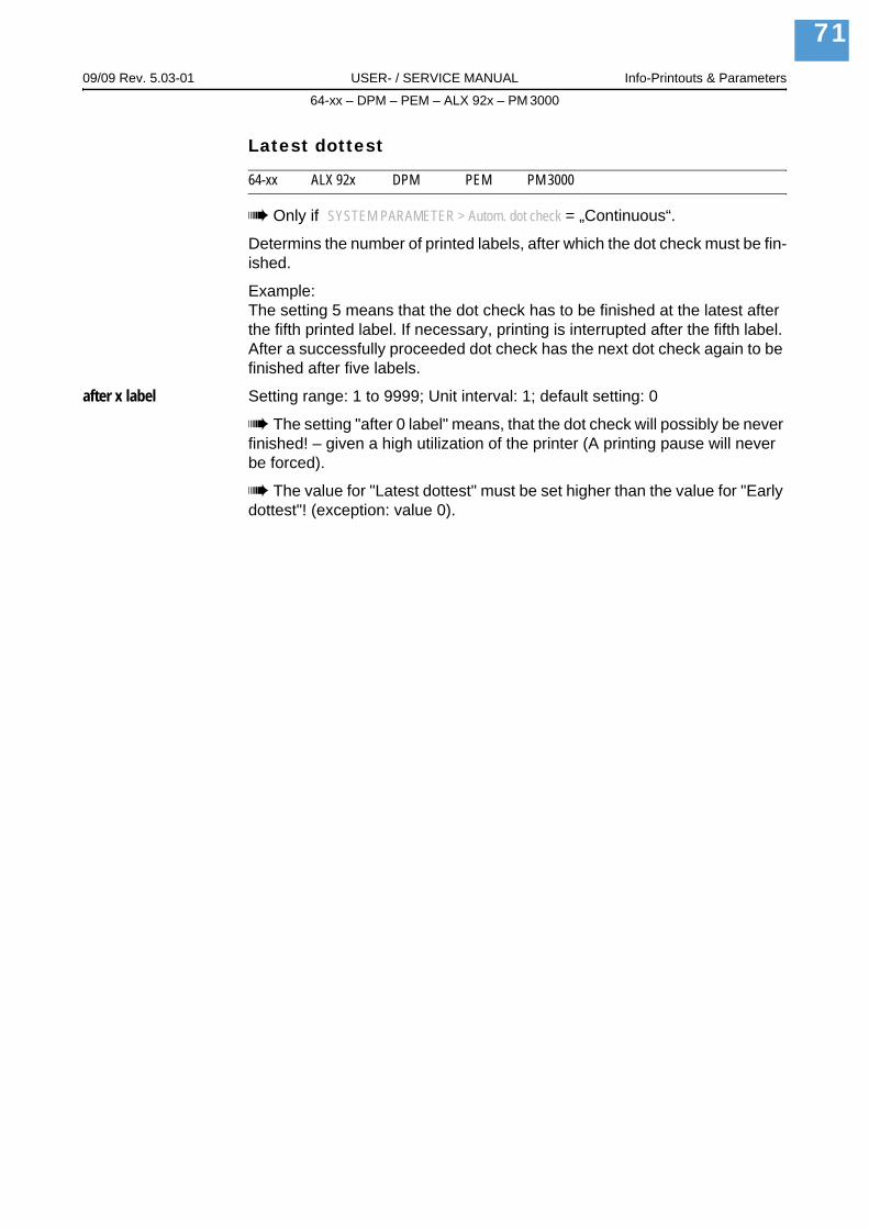
09/09 Rev. 5.03-01 USER- / SERVICE MANUAL Info-Printouts & Parameters
64-xx – DPM – PEM – ALX 92x – PM 3000
71
Latest dottest
64-xx ALX 92x DPM PEM PM 3000
Only if SYSTEM PARAMETER > Autom. dot check = „Continuous“.
Determins the number of printed labels, after which the dot check must be fin-ished.
Example:The setting 5 means that the dot check has to be finished at the latest after the fifth printed label. If necessary, printing is interrupted after the fifth label. After a successfully proceeded dot check has the next dot check again to be finished after five labels.
after x label Setting range: 1 to 9999; Unit interval: 1; default setting: 0
The setting "after 0 label" means, that the dot check will possibly be never finished! – given a high utilization of the printer (A printing pause will never be forced).
The value for "Latest dottest" must be set higher than the value for "Early dottest"! (exception: value 0).

09/09 Rev. 5.03-01 USER- / SERVICE MANUAL Info-Printouts & Parameters
64-xx – DPM – PEM – ALX 92x – PM 3000
72
Dottestarea from
64-xx ALX 92x DPM PEM PM 3000
Only if SYSTEM PARAMETER > Autom. dot check = „Continuous“.
Limitates the area of a print head, in which the dots are checked. The param-eter sets the lower border of the dot check area. The value equals the dis-tance to the left print head end in mm, looked at the print head from above (see Fig. 13).
x mm Setting range: refer to Tab. 3; Unit interval: 1; default setting: 0 mm
[16] Dot check area (=Dottestarea) of the printer (schematic).
Dottestarea to
64-xx ALX 92x DPM PEM PM 3000
Only if SYSTEM PARAMETER > Autom. dot check = „Continuous“.
Upper border of the dot check area. The value sets the distance in mm to the left print head end, looked at on the print head from above.
x mm Setting range: refer to Tab. 3; Unit interval: 1; Default setting: 0 mm
Printer type Setting range in mm No. of dotss64-04 / Chess 4 0-107 128064-05 / Chess 5 0-128 153664-06 / Chess 6 0-160 192064-08 / Chess 8 0-214 2560
[8] Setting range for the dot check, depending on the print head width. Right column: Total number of dots of the print head.
0mm 128 mm
vonfrom
bisto
printhead
DottestbereichDottestarea
Display 2x16characters
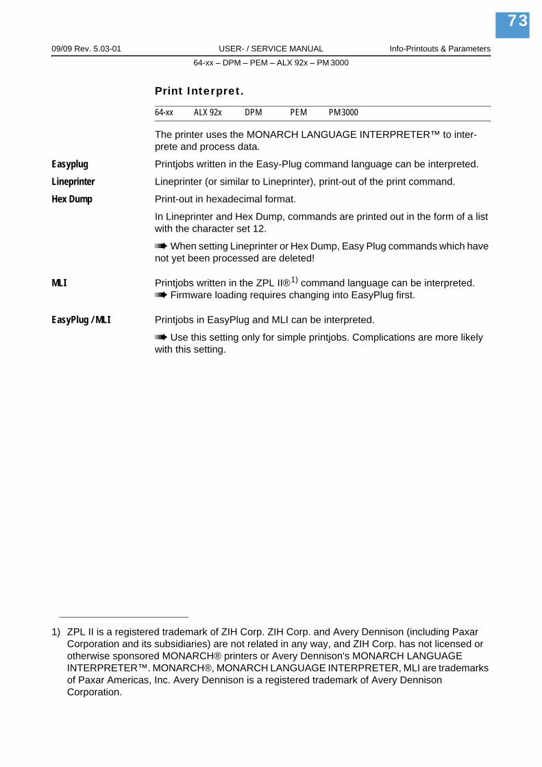
09/09 Rev. 5.03-01 USER- / SERVICE MANUAL Info-Printouts & Parameters
64-xx – DPM – PEM – ALX 92x – PM 3000
73
Print Interpret.
64-xx ALX 92x DPM PEM PM 3000
The printer uses the MONARCH LANGUAGE INTERPRETER™ to inter-prete and process data.
Easyplug Printjobs written in the Easy-Plug command language can be interpreted.
Lineprinter Lineprinter (or similar to Lineprinter), print-out of the print command.
Hex Dump Print-out in hexadecimal format.
In Lineprinter and Hex Dump, commands are printed out in the form of a list with the character set 12.
When setting Lineprinter or Hex Dump, Easy Plug commands which have not yet been processed are deleted!
MLI Printjobs written in the ZPL II®1) command language can be interpreted.Firmware loading requires changing into EasyPlug first.
EasyPlug / MLI Printjobs in EasyPlug and MLI can be interpreted.
Use this setting only for simple printjobs. Complications are more likely with this setting.
1) ZPL II is a registered trademark of ZIH Corp. ZIH Corp. and Avery Dennison (including Paxar Corporation and its subsidiaries) are not related in any way, and ZIH Corp. has not licensed or otherwise sponsored MONARCH® printers or Avery Dennison's MONARCH LANGUAGE INTERPRETER™. MONARCH®, MONARCH LANGUAGE INTERPRETER, MLI are trademarks of Paxar Americas, Inc. Avery Dennison is a registered trademark of Avery Dennison Corporation.

09/09 Rev. 5.03-01 USER- / SERVICE MANUAL Info-Printouts & Parameters
64-xx – DPM – PEM – ALX 92x – PM 3000
74
Character sets
64-xx ALX 92x DPM PEM PM 3000
Setting the character set:
8bit: Choose between IBM and ANSI character set.7Bit: Additionally to the IBM and ANSI character sets, some country specific character sets are provided, which have some characters allocated differently (see table below)
The country specific character sets are only suitable for older 7bit applications!
For complete tables of all fixfonts characters available with setting "IBM" refer to the User Manual, topic section "Internal Fonts". You also find there a comparison of the IBM and ANSI character sets.
Decimal 35 36 64 91 92 93 94 96 123 124 125 126 >127
ASCII # $ @ [ \ ] ^ ‘ { | } ~
ISO 8859-2 a) # $ @ [ \ ] ^ ` { | } ~ print
ANSI (CP 1250) a) # $ @ [ \ ] ^ ` { | } ~ print
ANSI (CP 1252) # $ @ [ \ ] ^ ` { | } ~ print
IBM # $ @ [ \ ] ^ ` { | } ~ print
Special ƒ ¢ blank blank ¼ ½ blank blank « • » ± blank
Norway # $ @ Æ ¥ Å ^ ` æ ¢ å ~ blank
Spain # $ @ i Ñ Ç ^ ` ¿ ñ ç ~ blank
Sweden # • É Ä Ö Å Ü é ä ö å ü blank
Italy Š $ § ° ç é ^ ù à ò è ` blank
Germany # $ § Ä Ö Ü ^ ` ä ö ü ß blank
France £ $ à ° ç § ^ ` é ù è ~ blank
United Kingdom £ $ @ [ \ ] ^ ` { | } ½ blank
USA # $ @ [ \ ] ^ ` { | } ~ blank
blank = space, print = printable
[9] Country settings for applications, which base on 7bit ASCII code.a) Not available with AP 4.4
09/09 Rev. 5.03-01 USER- / SERVICE MANUAL Info-Printouts & Parameters
64-xx – DPM – PEM – ALX 92x – PM 3000
75
Character filter
64-xx ALX 92x DPM PEM PM 3000
Character >= 20Hex Filter function is activated. Characters smaller than 20H are filtered out of the data flow.
All character Filter function is deactivated. Characters smaller than 20H are treated as nor-mal characters.
Light sens. type
64-xx ALX 92x DPM PEM PM 3000
Light sensor type
The optional reflex photoelectric switch for labels with reflecting length mark-ings, or the normal factory-fitted photoelectric switch for labels with transpar-ent or register gaps (self-adhesive labels), must be defined according to the application.
Full Size Full Size photoelectric switch (Adjustment range is the material width).
Reflex Reflex photoelectric switch (for reflecting markings)
Punched Transparent photoelectric switch (for gaps)
Head-sensor dist.
64-xx ALX 92x DPM PEM PM 3000
Parameter appears only in production mode or if a value > 0 is set.
Printhead-sensor distance
Special function for setting non-standard punch sensors. Such sensors can be applied in special application devices ("Nistan"). The value x is the dis-tance between thermal edge and punch sensor in millimeters.
x mm Setting range: 0 to 400 mm
A „non standard sensor“ must be installed and connected instead of the regular punch sensor.
0 = disabled (the regular punch sensor is used).

09/09 Rev. 5.03-01 USER- / SERVICE MANUAL Info-Printouts & Parameters
64-xx – DPM – PEM – ALX 92x – PM 3000
76
Sens. punch-LS
64-xx ALX 92x DPM PEM PM 3000
Sensitivity punch light sensor
Sets the sensitivity of the material photoelectric switch.
xxx% Setting range: 10 to 100%; Unit interval: 10%Default setting: 50%
Maximum sensitivity: 100%. for narrow gaps (perforations).
Minimum sensitivity: 1%. for clearly detectable gaps.
Too high a level of sensitivity can lead to gaps being detected which do not even exist (on proofs, material thickness fluctuations, perforations etc.).
Ribbon autoecon.
64-xx ALX 92x DPM PEM PM 3000
Ribbon automatic economy mode
The ribbon feed can be interrupted during print periods with the ribbon auto-matic economy parameter. This saves ribbon, particularly with long labels with a minimum print area. The automatic function should only be activated with unprinted areas from approx. 10 mm in length.
A selection can be made between thermal transfer printing and thermal direct printing. It is necessary to select the type of printing in order to be able to switch over the ribbon end detection.
Thermal printing Thermal direct printing (Ribbon-end-LS switched off)
Activated (not with AP 4.4/5.4)
Thermal transfer printing with ribbon automatic economy mode on.
Deactivated Thermal transfer printing with ribbon automatic economy mode off.
Ribbon economy limit
64-xx ALX 92x DPM PEM PM 3000
The ribbon economy limit determins the length of the printing free area on the label from that on the ribbon economy automatic should be activated.
x,xx mm Setting range: xx up to 100,0 mm; Unit interval: 0,1 mm (the initial value de-pends on the feed speed)Default-value: 5.0 mm

09/09 Rev. 5.03-01 USER- / SERVICE MANUAL Info-Printouts & Parameters
64-xx – DPM – PEM – ALX 92x – PM 3000
77
Feed mode
64-xx DPM PEM ALX 92x PM 3000
Head up (Default) The printhead is lifted during label material initialization and label feeding.
Head down The printhead is down during label material initialization and label feeding.
Turn-on mode
64-xx ALX 92x DPM PEM PM 3000
Operating mode of the printer after it has been switched on.
Online Printer starts in on-line mode.
Offline Printer starts in off-line mode.
Standalone Printer starts in standalone mode.
Error reprint
64-xx ALX 92x DPM PEM PM 3000
If an error occurs while a label is printed, the last printed label will normally be reprinted. In case of label layouts containing variable data like e.g. count fields, switching off the reprint function possibly makes sense.
Enabled Reprint in error cases (default setting)
Disabled No reprint in error cases.
EasyPlug error
64-xx ALX 92x DPM PEM PM 3000
Handling of errors caused by faulty Easy-Plug commands.
Tolerant handl. The label is printed, after the Easy-Plug/Bitimage error was acknowledged (default setting).
Strict handling The Easy-Plug command, which caused the error, is displayed after approx. 2 seconds in the lower display line. The displayed text is up to 30 characters long and is scrolled automatically.
If a single character caused the error, this character is marked with „>> <<„ in the display text, to facilitate the detection.
By pressing the cut button, the display can be toggled between error mes-sage and Easy-Plug command text.
After acknowledging the first occured Easy-Plug error, the printjob and the spooler are deleted (as by #!CA). This prevents the printing of labels with for-mat errors.

09/09 Rev. 5.03-01 USER- / SERVICE MANUAL Info-Printouts & Parameters
64-xx – DPM – PEM – ALX 92x – PM 3000
78
Single job mode
64-xx ALX 92x DPM PEM PM 3000
In single job mode (also stop mode) the printer stops after every job and waits until the operator restarts the print process.
Deactivated Single job mode is switched off (default setting).
Activated Single job mode is switched on. The printer always displays "Start next job", before starting a new print job. This requests the user to acknowledge by pressing the Online button.
Head resistance
64-xx ALX 92x DPM PEM PM 3000
For optimum print quality, the individual print head resistance of the thermo head employed in the device must be set once with this parameter.
When replacing the print head, the resistance value of the print head (to be read off from the print head) must be entered again.
CAUTION! - Entering a false value can damage the print head!
Read off the correct value from the print head and set it accordingly.The value set here remains when the factory settings are carried out.
xxxx Ohm Setting range: 1000 to 1500 Ohm; Unit interval: 1 Ohm
Setting the print head resistance:
Setting:
1. From the print head, read off the resistance value to be set and make a note of it (1000 to 1500).
2. In off-line mode press the Prog. button, display: PRINT INFO.
3. Press the Cut button until SYSTEM PARAMETER is displayed.
4. Press the Online button, display:
5. Press the Cut button until the following is displayed:
6. Press the Online button, set value is displayed.
7. Set the previously noted resistance value of the print head using the Feed and Cut buttons.
8. Press the Online button to confirm the set value.
9. Press the Prog. button to return to the display OFFLINE 0 JOBS.
SYSTEM PARAMETERFoil end warning
SYSTEM PARAMETERHead resistance

09/09 Rev. 5.03-01 USER- / SERVICE MANUAL Info-Printouts & Parameters
64-xx – DPM – PEM – ALX 92x – PM 3000
79
Temp. reduction
64-xx ALX 92x DPM PEM PM 3000
Reduction in the print head temperature
The parameter SYSTEM PARAMETER > Temperature reduct. allows the power supply to be reduced in the event of an increase in the print head temperature, there-by ensuring an evenly good print image.
xxx% Setting range: 0 to 100%; Unit interval: 5%
The following setting alternatives are available:
0%: No temperature reduction.xx%: Up to xx% temperature reduction with a hot print head.Default setting: 20%.
For further information refer to the user manual, topic section „Advanced Application“, chapter „Printing with Termperature Compensation“
Voltage offset
64-xx ALX 92x DPM PEM PM 3000
The voltage offset increases the head voltage and therefore the head tem-perature which e.g. was set by Easy Plug command (HV).
xx% Setting range: 0 to 20%; Unit interval: 1%Default setting: 0%
Expand Logo
64-xx ALX 92x DPM PEM PM 3000
Only with 8-Dot emulation.
Off Logos are printed in normal size.
On Logos are printed enlarged.
09/09 Rev. 5.03-01 USER- / SERVICE MANUAL Info-Printouts & Parameters
64-xx – DPM – PEM – ALX 92x – PM 3000
80
Miss. label tol.
64-xx ALX 92x DPM PEM PM 3000
Missing label tolerance
The maximum search path for gaps which cannot be found can be varied. In cases of difficult gap detection (i. e. minimum variation in the light transpar-ency, gap to label), shortening the search path is to be recommended. Label loss resulting from gaps not being detected can be reduced in this way. Print-ing does not take place during the search process.
xx Setting range: 0 to 50; Unit interval: 1
Example 0 (Zero label length): A gap must be found after a printed label otherwise an error message is given. This setting is for detecting every missing label.
Example 5 (Five label lengths): A gap must be found after a maximum of 5 label lengths otherwise an error message is given.
Gap detect mode
64-xx ALX 92x DPM PEM PM 3000
After one of the following events, the printer must always search for the punch, that is initialize the label material:
After switching the printer onAfter changing the label material
Manual The operator has to initialize the material always manually by pressing the feed key several times.
Autom. Forward (Default for printers) The material initialization is always done automatically, if necessary. There is no backward movement of the material during the ini-tialization.
Autom. feed back Only 64-xx Dispenser, ALX 92x, DPM/PEM
(Default for those devices) The material initialization is always done automat-ically, if necessary. The label material is moved forward and backward during the initialization. The stretch of backward movement can be set with param-eter SYSTEM PARAMETER > Max InitFeedback (see below).

09/09 Rev. 5.03-01 USER- / SERVICE MANUAL Info-Printouts & Parameters
64-xx – DPM – PEM – ALX 92x – PM 3000
81
Foil stretching
64-xx PEM PM 3000
Only in Production mode.64-xx: Only standard printers (without dispenser).
After stopping and restarting the print process, the print quality can fall off for a short stretch in the area printed first after the restart. The reason for this be-haviour is the foil tension, which relaxes slightly due to the stopping.
The foil stretching function feeds the label material backwards for the defined stretch befor restarting the print process. Afterwards, feeding starts befor the printing. This stretches the foil before printing starts.
Advantage: High print quality from the beginningDisadvantage: Higher foil consumption; lower label rate
Feedback = xx mm Setting range: 0 to 20 mm; Step width: 1 mm; Default setting: 5 mm
Max InitFeedback
64-xx ALX 92x DPM PEM PM 3000
64-xx: Only with dispenser version.
Only if SYSTEM PARAMETERS > Gap detect mode = „Autom. feed back“.
During initialization, the label material is fed back until the next punch/reflex mark is reached. This parameter defines the maximum admissible back-wards feeding length.
xx mm Setting range: 0 to 200 mm; Step width: 1 mm; Default setting: 80 mm
Mat.end detect.
64-xx ALX 92x DPM PEM PM 3000
Material end detection.
The material end detection can be deactivated for processing labels with gaps longer than 15 mm, or if using material with a high fluctuation in light transparency (ST05 = material end is displayed even though material is present).
CAUTION! - Reel material should not be processed when the material end detection is deactivated! With this setting, printing continues on the print roller after the end of the material, leading to shorter cleaning intervals or damage.
Reflex Material end detection by means of a reflex sensor.
Transparent Material end detection by means of a transmission sensor.
Disabled No material end detection.

09/09 Rev. 5.03-01 USER- / SERVICE MANUAL Info-Printouts & Parameters
64-xx – DPM – PEM – ALX 92x – PM 3000
82
Periph. device
64-xx
After installation, options must be selected under "Peripheral device" in order to be assured of the corresponding sensor queries and printer reactions.
CAUTION! - Selecting an incorrect option can lead to malfunctions or damage!
None No peripheral device is installed.
Cutter Sets the printer firmware to the cutter option. Selection permits access to the cut parameters.
Rewinder Sets the printer firmware to the rewinder option. Selection permits access to the rewinder setting parameters.
Tear-off edge Sets the printer firmware to the tear-off edge option. The punch is fed forward to the tear-off edge.
Dispenser Setting for 64-xx dispenser version.
64-04/05 only: After selecting this value, the parameter SPECIAL FUNCTION > Disp. Head Offs. appears automatically, if the parameter SPECIAL FUNCTION > Printhead type is set to „KCE 4 Inch“.
See parameter Disp. Head Offs. / on page 119.See parameter Printhead type / on page 119.
Singlestartquant
64-xx ALX 92x DPM PEM PM 3000
Single start quantity
xx Setting range: 1 to 10; Unit interval: 1
External signal
64-xx ALX 92x DPM PEM PM 3000
The parameter determines, if and how an incoming signal at the - optional - single start connector will be interpreted.
Disabled Signal interpretation disabled.
Singlestart The signal triggers the printing of a single label. This setting may be used e.g. for printing single labels by means of a foot switch.
Stacker full The signal triggers the display of a status report and stops the printer. This setting may be used when using a stacker (= stacker full signal).
Detailed information about using start signals can be found in the user man-ual, topic section „Advanced Applications“, chapter „Printing with start sig-nal“, Settings in the parameter menu

09/09 Rev. 5.03-01 USER- / SERVICE MANUAL Info-Printouts & Parameters
64-xx – DPM – PEM – ALX 92x – PM 3000
83
Dispensing mode
64-xx ALX 92x DPM PEM PM 3000
Only if SYSTEM PARAMETER > Periph. device = „Dispenser“.
Only effective in real 1:1 mode!
Real 1:1 mode normally bears the disadvantage of a slightly lower impression accuracy, caused by the additional slippage at the rollers while feeding back.
The parameter "Dispensing mode" enables optimal positioned printouts even in real 1:1 mode. This accuracy is reached by feeding back the next label to be printed behind the gap sensor instead of "only" as far as under the print head. The additional distance of backwards feeding reduces the output rate slightly.
exact Printout with a maximum impression accuracy
fast Printout with a lower impression accuracy but higher output rate.
Application mode
64-xx ALX 92x DPM
64-xx: Only if SYSTEM PARAMETER > Periph. device = „Dispenser“.
Save Mode A start signal is required to draw the next label back under the print head. This setting bears advantages for label material with a strong adhesive, which would not stay attached to the applicator when the backing paper is fed back-wards.
Immediate Mode After the just printed label has reached the dispense position, the following label is drawn back under the print head. The dispensed label stays attached to the applicator (default setting).
Synchronous mode Drawing back of the next label to be printed is triggered by the not active edge of the start signal. The active edge is defined with DP INTERFACE > Start print mode („Pulse rising“ or „Pulse falling“). Not active is the opposite signal edge.
USI: The setting „Synchronous mode“ is only available, if the following conditions are met:– USI firmware version: 7 or higher.– DP INTERFACE > Start print mode = „Pulse rising“ or „Pulse falling“.

09/09 Rev. 5.03-01 USER- / SERVICE MANUAL Info-Printouts & Parameters
64-xx – DPM – PEM – ALX 92x – PM 3000
84
Start mode
64-xx ALX 92x DPM PEM PM 3000
Settings for interpreting the start signal.
Only relevant for start signals coming from the following sources:– Foot switch connector (SYSTEM PARAMETERS > Start source = „Foot switch“)– D-Sub connector for dispensing edge light barrier (SYSTEM PARAMETERS >
Start source = „Light barrier“)– not USI
Detailed information about using start signals can be found in the user man-ual, topic section „Advanced Applications“, chapter „Printing with start sig-nal“, Settings in the parameter menu
Level Labels of a certain print job are being printed as long as the signal level is "high". When using a foot switch, labels are printed as long as somebody keeps his/her foot on the foot switch.
Edge The rising / falling signal edge triggers the printing of exactly one label (De-fault setting).
See parameter Signal edge / on page 89.
Start source
64-xx
64-xx dispenser only.
Choose a signal source for the start signal:
Foot switch The start signal is expected at the foot switch connector (optional connector on the printer rear side).
Light barrier (Default setting) The start signal is expected at the D-Sub connector at the front side of the printer (photoelectric switch at the dispensing edge which de-tects the taking off of the dispensed label).
The setting "Light barrier" is unsuitable for product sensors! Product sensors must be connected to an USI!
USI The start signal is expected at the USI interface (only with installed USI board).
For this setting, the parameter in the menu DP INTERFACE are relevant.
Detailed information about using start signals can be found in the user man-ual, topic section „Advanced Applications“, chapter „Printing with start sig-nal“, Settings in the parameter menu
09/09 Rev. 5.03-01 USER- / SERVICE MANUAL Info-Printouts & Parameters
64-xx – DPM – PEM – ALX 92x – PM 3000
85
Dispensing edge
64-xx
Only if SYSTEM PARAMETER > Periph. device = „Dispenser“.
Adapts the feeding to the length of the dispensing edge.
long Long dispensing edge
short Short dispensing edge (Default setting)
User defined The distance between print line and dispensing edge can be set by SYSTEM PARAMETER > Head disp dist (see below). This is helpful if none of the standard dispensing edges are applied.
Head disp distSee parameter Head disp dist. / on page 70.
Transport mode
64-xx
Only if SYSTEM PARAMETER > Periph. device = „Dispenser“.
In normal operation mode, the rewinder motor (Dispenser Motor) feeds the material, while the feed motor runs idle. When applying very slim material, it can be advisable to add the power of the feed motor in order to prevent ma-terial rupture (Dual Motors). To run the printer like a usual non-dispenser, the rewinder motor can be switched off (Printer Motor).
Absolutely use the "Dual Motors" mode, if the following three conditions are the case:
– Printer is used as dispenser– Ribbon autoeconomy mode switched on– Print speed higher than 203 mm/s (8 inch/s)
Printer Motor Rewinder motor switched off. The printer behaves like a model without dis-penser option.
Dual Motors Both motors (feed and rewinder) are activated.
Dispenser Motor The feed motor is switched off. The rewinder motor feeds the material (De-fault setting).

09/09 Rev. 5.03-01 USER- / SERVICE MANUAL Info-Printouts & Parameters
64-xx – DPM – PEM – ALX 92x – PM 3000
86
Signal edge
64-xx ALX 92x DPM PEM PM 3000
This parameter determins either the falling or the rising edge of an incoming signal as trigger.
Only relevant for start signals coming from the following sources:– Foot switch connector (SYSTEM PARAMETERS > Start source = „Foot switch“)– D-Sub connector (SYSTEM PARAMETERS > Start source = „Light barrier“)– not USI
Falling edge The falling signal edge triggers a certain printer reaction.
Rising edge The rising signal edge triggers a certain printer reaction.
Apply key
64-xx ALX 92x DPM PEM PM 3000
64-xx: Only if SYSTEM PARAMETER > Periph. device is set to „Dispenser“.
Parameter is displayed in production mode only.
Only if SYSTEM PARAMETERS > External signal is set to „Singlestart“
Enabled (Default) The application can be triggered by pressing the cut respectively apply key.
Disabled Triggering the application by pressing the cut/apply key is not possible.
Print contrast
64-xx ALX 92x DPM PEM PM 3000
xxx% Setting range: 1 to 110%; Unit interval: 1; Default setting: 60
CAUTION!
The parameter Print contrast affects directly the life durance of the printhead. It counts: „The higher the setting of Print contrast is, the lower is the life dur-ance of the printhead“. This counts even more for settings above 100%. Therefore mind:
Always choose the lowest possible setting necessary to produce an accep-table print result.
09/09 Rev. 5.03-01 USER- / SERVICE MANUAL Info-Printouts & Parameters
64-xx – DPM – PEM – ALX 92x – PM 3000
87
Ram disk size
64-xx ALX 92x DPM PEM PM 3000
A part of the printer memory can be identified as a RAM disk. The RAM disk can be used in the same way as the Compact Flash Card, e.g. for storage of logos or fonts.With the parameter Ram disk size, the customer can set the size of the RAM disk to his needs. Be aware, that RAM disk memory is not available for print picture buildup. Use of much RAM disk memory reduces the picture buildup rate of the printer.
Switching the printer off extinguishes the memory content! Fonts, logos etc., which were loaded on the RAM disk, must be loaded again after switching the printer off.
xxxx KBytes Setting range: 2048 KBytes to the maximum size, which depends on the memory configuration and allocation of the printer; Unit interval: 128 KBytes; Default setting: 512 KBytes
Font downl. area
64-xx ALX 92x DPM PEM PM 3000
If speedo-fonts are supposed to be used, they have first to be copied to a re-served RAM disk area. Use parameter „Font downl. area“ to reserve the RAM disk area in the required size.
The size of the required RAM disk area depends on the size of the font files to be loaded.
Mind to reserve a big enough RAM disk area!
There are two ways to copy the font files to the RAM disk:
Copy from CompactFlash card:The font files must be placed in a folder named \fonts on the CompactFlash card during system startup. The files must be named fontxxx.spd (xxx = No. from 200 up to 999).
For details refer to the manual „Cards“, subject section „Using Cards“, paragraph „CompactFlash Card“.Copy via Easy Plug command #DF (download file).
More information: manual „Easy Plug“, subject section „Description of Commands“.
xxx KBytes Setting range: 128 KBytes to the maximum size, which depends on the mem-ory configuration and allocation of the printer; Unit interval: 128 KBytes; De-fault setting: 256 KBytes
Switching the printer off extinguishes the memory content! Fonts, logos etc., which were loaded on the RAM disk, must be loaded again after switching the printer off.

09/09 Rev. 5.03-01 USER- / SERVICE MANUAL Info-Printouts & Parameters
64-xx – DPM – PEM – ALX 92x – PM 3000
88
Free store size
64-xx ALX 92x DPM PEM PM 3000
By setting this parameter, a part of the memory is reserved, which the printer firmware can use if necessary (dynamic memory allocation). If this memory area is dimensioned too small, the printer firmware can not work and the error message „8856 Free store size“ shows up.
The more memory is allocated using this parameter, the less memory is available for print jobs.
xxx KBytes Setting range: 2048 KBytes to the maximum size, which depends on the memory configuration and allocation of the printer; Unit interval: 128 KBytes; Default setting: 2048 KBytes.
A good advice is to increase the set value step by step, starting with the mi-nimum of 2048 KBytes, until the status message 8856 ("Free store size", what means the memory area is low) does no longer appear during data con-version.
Use with the Easy Plug command #YG, see manual Easy Plug .See parameter Memory status / on page 26.
Print info mode
64-xx ALX 92x DPM PEM PM 3000
Structure option for info printouts.
Par. values right Setting for 100 mm material width. The parameter values are printed on the right side of the parameter names:
Parameter name: Value
Par. values left Setting for 100 mm material width. The parameter values are printed on the left side of the parameter names:
Value: Parameter name
Compact right Setting for 50 mm material width. The parameter values are printed on the right side of the parameter names:
Parameter name: Value
Compact left Setting for 50 mm material width. The parameter values are printed on the left side of the parameter names:
Value: Parameter name
Reprint function
64-xx ALX 92x DPM PEM PM 3000
Disabled (Default setting) Reprinting is not possible.
Enabled The last printed label can be reprinted by pressing the feed button in online mode, if the printer is not printing at that moment.

09/09 Rev. 5.03-01 USER- / SERVICE MANUAL Info-Printouts & Parameters
64-xx – DPM – PEM – ALX 92x – PM 3000
89
Language
64-xx ALX 92x DPM PEM PM 3000
Setting the display language.
TurkishPolishItalianDanishDutchSpanishFrenchEnglishGerman
Keyboard
64-xx ALX 92x DPM PEM PM 3000
Setting the keyboard layout country version for standalone operation.
TurkishPolishSwedishFinishDanishSpanishFrenchEnglishGerman
Signal / buzzer
64-xx ALX 92x DPM PEM PM 3000
On Tone signal activated
Off Tone signal deactivated
Access authoriz.
64-xx ALX 92x DPM PEM PM 3000
Access authorization
Limits the access either to all printer functions (Power-up code) or only to the parameter menu (user or supervisor mode). Changed settings become active after the next switch-on.
Key codes
Regardless when the code is prompted, can three different key codes be typed in tab. 10.

09/09 Rev. 5.03-01 USER- / SERVICE MANUAL Info-Printouts & Parameters
64-xx – DPM – PEM – ALX 92x – PM 3000
90
Entering a key code: Type the corresponding buttons of the control panel in succession. A valid key code switches the printer into the appropriate mode.
CAUTION! - The key code "production" allows the access to parameters, which are used during production to adjust the printer. Input errors to those parameters can make the printer inoperable or can damage it. For this reason, the production code may only be applied by trained service technicians!
Especially service technicians may use the direct access into production mode, even if the parameter Access authoriz. is set to Deactivated, what means that no password will be queried at all. To do so, proceed as follows:
1. Switch printer off.
2. Switch printer on, simultaneously press the Feed+Prog-key until the printer type is displayed.
After the printer was powered up, the key code will be queried:
3. Enter the production code.
Possible Settings
Deactivated Password interrogation switched off (default)
Power-up code Activates the password interrogation directly after switching the printer on.
After the input of a valid key code, the printer switches into offline mode. Depending on the entered key code, the printer starts in user, supervisor or production mode.
User Activates the password interrogation when accessing the parameter menu.The printer is in the offline mode after switch-onChange to the online mode is possible without restrictionTo reach the parameters-menu, enter a valid key codeValid key codes: all
Supervisor As setting „User“, with different valid key codes:Valid key codes: Supervisor, Production
User auto start (Not with AP 4.4) Printer starts without password interrogation. Only the menus PRINT INFO and SERVICE DATA are accessible.
Enter code
Mode Key code ImpactUser 2x Cut a), Feed, Online
a) With DPM, PEM, ALX 92x press Apply-key instead.
Access only to the submenus PRINT INFO and SERVICE DATA
Supervisor 2x Online, Feed, Cut, 2x Online Access to all parameters ex-cept production parameters
Production Cut, Online, Feed, Cut, 3x Online Access to all parameters
[10] Permissible key codes.

09/09 Rev. 5.03-01 USER- / SERVICE MANUAL Info-Printouts & Parameters
64-xx – DPM – PEM – ALX 92x – PM 3000
91
Realtime clock
64-xx ALX 92x DPM PEM PM 3000
The realtime clock provides actual date and time. Those data can be proc-esses using the Easy-Plug #YC, #YS or #DM commands.
Setting date / time:
1. Press the CUT(Apply) button repeatedly, until the digit blinks which you want to alter.
2. Set the intended value to the digit by pressing the FEED button (repeatedly).
3. Repeat steps 1 and 2 until date / time is set correctly.
4. Press the ONLINE button.
Press the ESC button to leave the parameter without altering the setting.
Material feed
64-xx ALX 92x DPM PEM PM 3000
Suppresses backwards material feeding.
For-/backwards Standard setting; material is fed forwards and backwards.
Only forwards The label material is only fed forwards. Printjobs, which contain commands for using R 1:1 or N 1:1 mode, are automatically printed in batch mode. The batch mode is modified in a way, that the label following after a printjob is not drawn back under the printhead, but is ejected in forward direction. The effect is, that one label stays unprinted between two succeeding printjobs.
Realtime Clockdd.mm.yyyy hh:mm
dd=Day, mm=Month, yyyy=Year, hh=Hour, mm=Minute (Example: 19.02.2001 14:41)
Print mode Feed direction following label„for-/backwards“ „Only forwards“
Batch <--> -->R 1:1 <--> Batch a)
a) The backwards movement is suppressed duringinitialization.
N 1:1 <--> Batch a)
[11] Suppression of the backward movement with the setting „Only forwards“. <--> = Material feeding in both direction; --> = Material feeding only forwards.
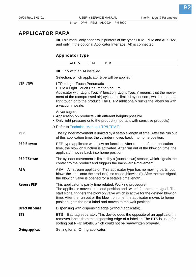
09/09 Rev. 5.03-01 USER- / SERVICE MANUAL Info-Printouts & Parameters
64-xx – DPM – PEM – ALX 92x – PM 3000
92
APPLICATOR PARAThis menu only appears in printers of the types DPM, PEM and ALX 92x,
and only, if the optional Applicator Interface (AI) is connected.
Applicator type
ALX 92x DPM PEM
Only with an AI installed.
Selection, which applicator type will be applied:
LTP-LTPV LTP = Light Touch PneumaticLTPV = Light Touch Pneumatic VacuumApplicator with „Light Touch“ function. „Light Touch“ means, that the move-ment of the (compressed air) cylinder is limited by sensors, which react to a light touch onto the product. The LTPV additionally sucks the labels on with a vacuum nozzle.
Advantages:Application on products with different heights possibleOnly light pressure onto the product (important with sensitive products)
Refer to Technical Manual LTP/LTPV .
PEP The cylinder movement is limited by a setable length of time. After the run out of this application time, the cylinder moves back into home position.
PEP Blow on PEP-type applicator with blow on function: After run out of the application time, the blow on function is activated. After run out of the blow on time, the applicator moves back into home position.
PEP II Sensor The cylinder movement is limited by a (touch down) sensor, which signals the contact to the product and triggers the backwards-movement.
ASA ASA = Air stream applicator. This applicator type has no moving parts, but blows the label onto the product (also called „blow box“). After the start signal, the blow on valve is opened for a setable time length.
Reverse PEP This applicator is partly time related. Working procedure: The applicator moves to its end position and “waits“ for the start signal. The start signal triggers the blow on valve which is active for the defined blow on time. After the run out or the blown on time, the applicator moves to home position, gets the next label and moves to the wait position.
Direct Dispense Dispensing with dispensing edge (without applicator).
BTS BTS = Bad tag separator. This device does the opposite of an applicator: it removes labels from the dispensing edge of a labeller. The BTS is used for sorting out RFID labels, which could not be read/written properly.
O-ring applicat. Setting for an O-ring applicator.

09/09 Rev. 5.03-01 USER- / SERVICE MANUAL Info-Printouts & Parameters
64-xx – DPM – PEM – ALX 92x – PM 3000
93
Application mode
ALX 92x DPM PEM
Only with an AI installed.
Defines, if the application process starts with applying („After start signal“) or with printing the label. Precondition: A printjob is loaded and the printer is in online mode.
After print The start signal triggers the immediate printing, dispensing and applying of a label.
After start sig. The start signal triggers the application of an already printed and dispensed label. After applying the label, the next one is immediately printed and dis-pensed.
A flow chart illustrating the application process can be found in the Technical Manual LTP/LTPV, topic section "Specifications", paragraph "Function diagram LTSI / LTP / LTPV".
Start print mode
ALX 92x DPM PEM
Only with an AI installed.
Selecting a print mode. Depending on the selected mode, the start signal will be interpreted differently by the AI.
Further information about using a start signal: Read the user manual, topic section „Advanced Applications“, chapter Printing with start signal .
This parameter has priority over SYSTEM PARAMETER > Signal edge, which is relevant for setting the triggering of the single start connector.
Pulse falling (Default setting) The printing of a label is triggered by a high-to-low change of the start signal. The printing occurs only after the set delay time.
Pulse rising The printing of a label is triggered by a low-high change of the start signal. The printing occurs only after the set delay time.
Pulse fall/ris The printing of a label is triggered by a low-high-change as well as by a high-low change of the start signal. The printing occurs only after the set delay time.
Level low active Labels will be printed as long as the start signal is held low.
Level high active Labels will be printed as long as the start signal is held high.

09/09 Rev. 5.03-01 USER- / SERVICE MANUAL Info-Printouts & Parameters
64-xx – DPM – PEM – ALX 92x – PM 3000
94
Start error stop
ALX 92x DPM PEM
Only with an AI installed.
Determines the reaction of the machine on a product start error. A product start error occurs in the following cases:
If a further start signal arrives, before the current label is completely printed.If a reprint is requested, before the first label after powering on is printed.If a start signal arrives and no printjob is loaded.
On Start errors are worked up (the machine stops!) (default setting)
Off Start errors are being ignored.
APSF sensor res.
ALX 92x DPM PEM
Only with an AI installed.
APSF sensor resolution.
This parameter is not yet supported.
Startdelay
ALX 92x DPM PEM
Only with an AI installed.
Use this parameter to set the distance between product sensor (photoelectric switch) and dispensing edge. The recommended delay time is calculated of the "Start delay" distance and the conveyor speed (= print speed in cases of direct application).
xxx.x mm Setting range: 0.0 to 999.9 mm; Unit interval: 0.1 mm; Default setting: 0 mm
Dwell time
ALX 92x DPM PEM
Only with an AI installed.
Only if APPLICATOR PARA > Applicator type = „PEP“ or „PEP Blow on“.
Defines the dwell time for the apply cylinder. The dwell time is the time during which the cylinder valve is turned on.
xxxxx ms Setting range: 1 to 99999 ms; Unit interval: 1 ms; Default setting: 1 ms

09/09 Rev. 5.03-01 USER- / SERVICE MANUAL Info-Printouts & Parameters
64-xx – DPM – PEM – ALX 92x – PM 3000
95
Blow on time
ALX 92x DPM PEM
Only with an AI installed.
Only if APPLICATOR PARA > Applicator type = „LTP-LTPV“ or „ASA“.
xxxxx ms Setting range: 0 to 99999 ms; Unit interval: 1 ms; Default setting: 1 ms
Restart delay
ALX 92x DPM PEM
Only with an AI installed.
Sets the delay time after the application, during which no start signals are accepted.
xxxxx ms Setting range: 0 to 99999 ms; Unit interval: 1 ms; Default setting: 0 ms
Position timeout
ALX 92x DPM PEM
Only with an AI installed.
Sets the delay time, after which a position error of the applicator is displayed as an error. A position error occurs, if the applicator doesn´t reach any of its end positions within the required time frame.
xxxxx ms Setting range: 500 to 99999 ms; Unit interval: 1 ms; Default setting: 2000 ms

09/09 Rev. 5.03-01 USER- / SERVICE MANUAL Info-Printouts & Parameters
64-xx – DPM – PEM – ALX 92x – PM 3000
96
I/O BOARDThis menu appears only if the optional I/O Board is mounted.
Start delay
64-xx ALX 92x DPM PEM PM 3000
Only with an I/O board mounted.
Use this parameter to set the distance between product sensor (photoelectric switch) and dispensing edge. The resulting delay time is calculated from the start delay (distance) and the print speed, so it leads to a delay time t = start delay (distance) / print speed.
xxx.x mm Setting range: 0.0 to 999.9 mm; Unit interval: 0.1 mm; Default setting: 0 mm
Start print mode
64-xx ALX 92x DPM PEM PM 3000
Only with an I/O board mounted.
Selecting a print mode. Depending on the selected mode, the input signal START_PRINT will be interpreted differently by the I/O Board signal inter-face. The parameter is also used for the device connected to the foot switch jack.
Make sure to select SYSTEM PARAMETER > External Signal = Single Start.See parameter External signal / on page 85.Note: The parameter Start Print Mode replaces the parameter Signal Edge in the SYSTEM PARAMETER menu.Preconditions: Print job is available (DATA READY), printer is in “Online” mode, no error messages.
Pulse falling (Default setting) The printing of a label is triggered by a high-to-low change of the signal at the input START PRINT. The printing occurs only after the set delay time.
Pulse rising The printing of a label is triggered by a low-high change of the signal at the input START PRINT. The printing occurs only after the set delay time.
Pulse fall/ris The printing of a label is triggered by a low-high-change as well as by a high-low change of the signal at the input START PRINT. The printing occurs only after the set delay time.
Level low active Labels will be printed as long as the signal at input START PRINT is held low.
Level high active Labels will be printed as long as the signal at input START PRINT is held high.

09/09 Rev. 5.03-01 USER- / SERVICE MANUAL Info-Printouts & Parameters
64-xx – DPM – PEM – ALX 92x – PM 3000
97
Reprint Signal
64-xx ALX 92x DPM PEM PM 3000
Only with an I/O board mounted.
Disabled The input signal is disabled
Enabled The last printed label will be reprinted on the falling edge of the REPRINT signal.
Preconditions:
The label to be reprinted, should be printed and dispensed.Printer is in online mode.
If a REPRINT is triggered while the printer is in “I/O-Board Pause” mode, the reprint will proceed as soon as the printer is switched back in online mode. Precon-dition: in level mode START PRINT must be inactive.
Feed input
64-xx ALX 92x DPM PEM PM 3000
Only with an I/O board mounted.
Concerns the input signal FEED at the signal interface.
Enabled (Default setting) Feeding of one label on the falling signal edge. The display shows „I/O board feed“ during feeding. Requirements are:
Offline mode, „stopped mode“ or „pause mode“Online mode and no print job loaded.
Disabled Signals at the FEED input are ignored.
Pause input
64-xx ALX 92x DPM PEM PM 3000
Only with an I/O board mounted.
Concerns the input signal PAUSE at the signal interface.
Disabled Signals at the PAUSE input are ignored.
Pause A high-to-low transition switches the printer into the “I/O-Board Pause” mode. The next high-low-transition switches the printer back into the online mode. If parameter I/O-Board > Start print mode is set to „Level high active“ or „Level low active“, any activating of the PAUSE signal stops the printing after the current label.
Features:
Printer display shows „I/O-Board pause“ERROR is active (only if I/O Board > Error output is set to „Printer err+Offl“)If a print job is available: DATA READY becomes inactive (if I/O Board > Status output is set to „Print job ready“)START PRINT signals are suppressed

09/09 Rev. 5.03-01 USER- / SERVICE MANUAL Info-Printouts & Parameters
64-xx – DPM – PEM – ALX 92x – PM 3000
98
REPRINT requests are processed after switching into online mode.
A "low" signal for 20 ms switches the printer into the pause mode. The pause mode is the same as the "Online stopped" mode and can be switched to the “Online” mode by pressing the feed button.
Error output
64-xx ALX 92x DPM PEM PM 3000
Only with an I/O board mounted.
This parameter defines different events, which activate the output signal ERROR.
Printer error ERROR will be activated in all of the following cases:
Material endRibbon end (only if SYSTEM PARAMETER > Foil mode = „Thermo transfer“)No punch recognized (only if PRINT PARAMETERS > Material type = „punched“)Printhead pressure lever was opened during the printing of a label.Start print errorOther errors, which keep the printer from printing
During the initialization (powering up) of the printer, the ERROR-signal is instable!
Printererr + Offl In addition to the above mentioned cases avtivate the following events the ERROR-signal:The printer is in offline modeThe printhead pressure lever is open„I/O board pause“ modeStopped mode (the printing was stopped)
Error Polarity
64-xx ALX 92x DPM PEM PM 3000
Only with an I/O board mounted.
Switches the polarity of the ERROR signal.
Level high activ The output is high when it is active, otherwise low.
Level low active The output is low when it is active, otherwise high. (Default)

09/09 Rev. 5.03-01 USER- / SERVICE MANUAL Info-Printouts & Parameters
64-xx – DPM – PEM – ALX 92x – PM 3000
99
Status output
64-xx ALX 92x DPM PEM PM 3000
Only with an I/O board mounted.
This parameter defines different events, which activate the output signal MACHINE STATUS.
Low ribbon warn The signal is activated, if the ribbon roll diameter is less than the limit.
See parameter Foil end warning / on page 71.Print job ready The signal is activated, if the printer has finished image processing and is
ready to start printing.
The signal is not activated, if:the print job is done,the print job was stopped,the printer was switched to offline mode,the printer is in pause mode.
Status polarity
64-xx ALX 92x DPM PEM PM 3000
Only with an I/O board mounted.
Switches the polarity of the MACHINE STATUS signal.
Level high active The output is high when it is active, otherwise low.
Level low active The output is low when it is active, otherwise high. (Default)
End print mode
64-xx ALX 92x DPM PEM PM 3000
Only with an I/O board mounted.
Concerns the output signal PRINT_END at the I/O board signal interface. Determines the signal response after printing of a label.
Mode0 inactve No print end signal.
Mode1 high level Low, if the print module is just printing a label, otherwise high.The output is also deactivated (= low) as long as labels are fed with “Feed Button” or “Feed Signal”.
Mode2 low level High, if the print module is just printing a label, otherwise low.The output is also deactivated (= high) as long as labels are fed with “Feed Button” or “Feed Signal”.
Mode3 low pulse (Default setting) Low for 20 ms after printing and dispensing a label.The output is also activated (= low) after a label is fed with “Feed Button” or “Feed Signal”.
Mode4 high pulse High for 20 ms after printing and dispensing a label.The output is also activated (= high) after a label is fed with “Feed Button” or “Feed Signal”.

09/09 Rev. 5.03-01 USER- / SERVICE MANUAL Info-Printouts & Parameters
64-xx – DPM – PEM – ALX 92x – PM 3000
100
OLV PARAMETERSThis menu only appears, if an online verifier (OLV) is connected to the
printer. For this, the parameter INTERFACE PARA > COM2 PORT > Function Option must be set to „Barcode OLV“.
Verify mode
64-xx ALX 92x DPM PEM PM 3000
Only if OLV PARAMETER > Cancel. printing = „Enabled“.
All bar codes All bar codes are being checked according to the limits set at the printer.
Easy-Plug print jobs don´t have to be modified when using this setting.
Easyplug select. Only those bar codes are being verified, which have the „V“ set in the com-mand option.
For details refer to the Easy-Plug manual, command #YB.
Ref Decode
64-xx ALX 92x DPM PEM PM 3000
Only if OLV PARAMETER > Cancel. printing = „Enabled“.
No Test The bar code doesn´t have to be decodable.
Pass The bar code must be decodable.
Decodability
64-xx ALX 92x DPM PEM PM 3000
Only if OLV PARAMETER > Cancel. printing = „Enabled“.
Condition: Value >= Limit.
xxx Setting range: -1 to 100; Unit interval: 1; -1 = No checking.
Modulation
64-xx ALX 92x DPM PEM PM 3000
Only if OLV PARAMETER > Cancel. printing = „Enabled“.
Condition: Value >= Limit.
xxx Setting range: -1 to 100; Unit interval: 1; -1 = No checking.

09/09 Rev. 5.03-01 USER- / SERVICE MANUAL Info-Printouts & Parameters
64-xx – DPM – PEM – ALX 92x – PM 3000
101
Defects
64-xx ALX 92x DPM PEM PM 3000
Only if OLV PARAMETER > Cancel. printing = „Enabled“.
Condition: Value <= Limit.
xxx Setting range: -1 to 100; Unit interval: 1; -1 = No checking.
Edge contrast
64-xx ALX 92x DPM PEM PM 3000
Only if OLV PARAMETER > Cancel. printing = „Enabled“.
Condition: Value >= Limit.
xxx Setting range: -1 to 100; Unit interval: 1; -1 = No checking.
Rmin/Rmax
64-xx ALX 92x DPM PEM PM 3000
Minimaler/maximaler Reflexionsgrad.
Only if OLV PARAMETER > Cancel. printing = „Enabled“.
Condition: Value <= Limit.
xxx Setting range: -1 to 100; Unit interval: 1; -1 = No checking.
Symbol contrast
64-xx ALX 92x DPM PEM PM 3000
Only if OLV PARAMETER > Cancel. printing = „Enabled“.
Condition: Value >= Limit.
xxx Setting range: -1 to 100; Unit interval: 1; -1 = No checking.
PCS
64-xx ALX 92x DPM PEM PM 3000
Print Contrast Signal.
Only if OLV PARAMETER > Cancel. printing = „Enabled“.
Condition: Value >= Limit.
xxx Setting range: -1 to 100; Unit interval: 1; -1 = No checking.

09/09 Rev. 5.03-01 USER- / SERVICE MANUAL Info-Printouts & Parameters
64-xx – DPM – PEM – ALX 92x – PM 3000
102
R (white)
64-xx ALX 92x DPM PEM PM 3000
Reflectance.
Only if OLV PARAMETER > Cancel. printing = „Enabled“.
Condition: Value >= Limit.
xxx Setting range: -1 to 100; Unit interval: 1; -1 = No checking.
R (black)
64-xx ALX 92x DPM PEM PM 3000
Reflectance.
Only if OLV PARAMETER > Cancel. printing = „Enabled“.
Condition: Value <= Limit.
xxx Setting range: -1 to 100; Unit interval: 1; -1 = No checking.
Ratio
64-xx ALX 92x DPM PEM PM 3000
Only if OLV PARAMETER > Cancel. printing = „Enabled“.
Condition: Value >= Limit.
xxx Setting range: -1 to 99; Unit interval: 1; -1 = No checking.
ANSI symbol grade
64-xx ALX 92x DPM PEM PM 3000
Only if OLV PARAMETER > Cancel. printing = „Enabled“.
Condition: Value >= Limit.
For most applications, it is sufficient to set only this parameter. The previously listed parameters are checked automatically according to ANSI grade.
xxx Setting range: -1 to 40; Unit interval: 1; -1 = No checking.
Value ANSI Grade0-5 F5-15 D
15-25 C25-35 B35-40 A
[12] ANSI symbol grades

09/09 Rev. 5.03-01 USER- / SERVICE MANUAL Info-Printouts & Parameters
64-xx – DPM – PEM – ALX 92x – PM 3000
103
Dist. head-beam
64-xx ALX 92x DPM PEM PM 3000
For most applications, it is sufficient to set only this parameter. The previously listed parameters are checked automatically according to ANSI grade.
Setting of the distance between reading position of the laser beam and print head.
xx mm Setting range: 6 to 18; Unit interval: 1
Cancel. printing
64-xx ALX 92x DPM PEM PM 3000
64-xx: Parameter is not supported for dispenser version.
Cancellation printing
Disabled No cancellation printing.
Enabled If no validation data for the printed bar code was sent, or if the bar code ex-ceeds the set limits, the faulty printed label is cancelled. Afterwards, the same label is reprinted. The amount of reprints can be set with the parameter „Re-print quantity“. If the error still occurs after the so defined quantity of labels was reprinted, the printing stops and an adequate error message appears.
Reprint quantity
64-xx ALX 92x DPM PEM PM 3000
Only, if OLV PARAMETER > Cancel. printing = „Enabled“.
Defines the maximum amount of reprint attempts after a bar code read error.
xxx Setting range: 0 to 10, Unit interval: 1; Default setting: 0
Verify mode
64-xx ALX 92x DPM PEM PM 3000
Fast Standard verification mode.
Slow Each print job is proceeded as if it contained counting fields. Additionally, each labels is moved forward underneath the laser beam and backwards again. This procedure slows down the label throughput, but on the other hand it ensures that the correct counting field content is printed after an error oc-cured.

09/09 Rev. 5.03-01 USER- / SERVICE MANUAL Info-Printouts & Parameters
64-xx – DPM – PEM – ALX 92x – PM 3000
104
DP INTERFACEThe parameters described in this section only appear in the parameter
menu after a USI board is mounted.
For information on signals and pin assignment of the USI, refer to the Service Manual, topic section "Electronics", chapter "USI board".
Interface type
64-xx ALX 92x DPM PEM PM 3000
Only with USI board.
Sets the machine to the used application procedure.
USI interface Setting for direct dispensing.
USI applicator Setting for operation of an applicator with additional PLC.
Start delay
64-xx ALX 92x DPM PEM PM 3000
Only with USI board.
Use this parameter to set the distance between product sensor (photoelectric switch) and dispensing edge. The recommended delay time is calculated of the "Start delay" distance and the conveyor speed (= print speed in cases of direct application).
xxx.x mm Setting range: 0.0 to 999.9 mm; Unit interval: 0.1 mm;Default setting: 0 mm
The start delay setting works only with one of the following settings of the parameter "Start Print Mode":
Parameter SettingStart print mode Pulse falling
Pulse risingPulse fall/ris
[13] Precondition for the use of "Start delay": One of those parameter settings must be choosen.
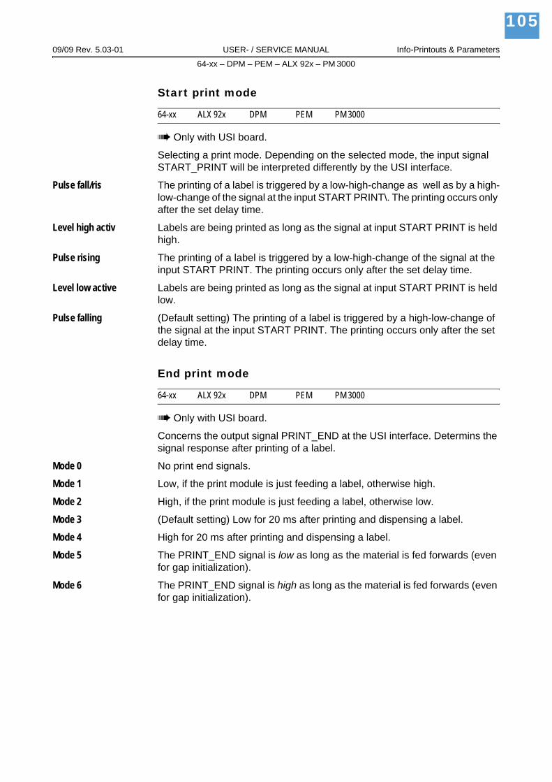
09/09 Rev. 5.03-01 USER- / SERVICE MANUAL Info-Printouts & Parameters
64-xx – DPM – PEM – ALX 92x – PM 3000
105
Start print mode
64-xx ALX 92x DPM PEM PM 3000
Only with USI board.
Selecting a print mode. Depending on the selected mode, the input signal START_PRINT will be interpreted differently by the USI interface.
Pulse fall/ris The printing of a label is triggered by a low-high-change as well as by a high-low-change of the signal at the input START PRINT\. The printing occurs only after the set delay time.
Level high activ Labels are being printed as long as the signal at input START PRINT is held high.
Pulse rising The printing of a label is triggered by a low-high-change of the signal at the input START PRINT. The printing occurs only after the set delay time.
Level low active Labels are being printed as long as the signal at input START PRINT is held low.
Pulse falling (Default setting) The printing of a label is triggered by a high-low-change of the signal at the input START PRINT. The printing occurs only after the set delay time.
End print mode
64-xx ALX 92x DPM PEM PM 3000
Only with USI board.
Concerns the output signal PRINT_END at the USI interface. Determins the signal response after printing of a label.
Mode 0 No print end signals.
Mode 1 Low, if the print module is just feeding a label, otherwise high.
Mode 2 High, if the print module is just feeding a label, otherwise low.
Mode 3 (Default setting) Low for 20 ms after printing and dispensing a label.
Mode 4 High for 20 ms after printing and dispensing a label.
Mode 5 The PRINT_END signal is low as long as the material is fed forwards (even for gap initialization).
Mode 6 The PRINT_END signal is high as long as the material is fed forwards (even for gap initialization).

09/09 Rev. 5.03-01 USER- / SERVICE MANUAL Info-Printouts & Parameters
64-xx – DPM – PEM – ALX 92x – PM 3000
106
Reprint signal
64-xx ALX 92x DPM PEM PM 3000
Only with USI board.
Determins the reaction on an incoming signal at pin REPRINT\ at the USI.
Disabled (Default setting) Incoming signal is ignored.
Enabled On a high-low toggle of the signal: The last printout is repeated.
Ribbon signal
64-xx ALX 92x DPM PEM PM 3000
Only with USI board.
Concerns the output signal WARNING at the USI, which signalizes the close shortness of ribbon or material.
Enabled (Default setting) High, if the ribbon stack is less than the threshold value.
The threshold setting is done with the parameter SYSTEM PARAMETER > Foil end warning.
Disabled Ribbon signal deactivated.
Material signal
64-xx ALX 92x DPM PEM PM 3000
Only with USI board.
Concerns the output signal WARNING at the USI, which indicates the close shortness of ribbon or material.
Enabled High, if the diameter of the material roll falls below a certain value. The limit diameter is set by positioning the outer diameter (OD) sensor.
Requirement: "OD sensor material" is installed.
Disabled No material end warning.

09/09 Rev. 5.03-01 USER- / SERVICE MANUAL Info-Printouts & Parameters
64-xx – DPM – PEM – ALX 92x – PM 3000
107
Mat. signal stop
64-xx ALX 92x DPM PEM PM 3000
Only with USI board.
Defines the reaction of the printer on a material low signal coming from the OD-sensor.
See DP INTERFACE > Material signal
Disabled (Default) The output signal WARNING at the USI is activated (precondition: DP INTERFACE > Material signal is set to „enabled“). The printing will be continued.
Enabled After a material low warning occured, the printer finishes printing the current label and stops afterwards. The display shows:
After acknowledging the message, the printing can be continued.
Feed input
64-xx ALX 92x DPM PEM PM 3000
Only with USI board.
Concerns the output signal FEED at the USI.
Standard (Default setting) Feed of blank labels as long as signal is "low".Precondition: Off-line mode or printing stopped in on-line mode.
JP5 A signal different from the standard FEED can be used. Precondition: an ap-propriate firmware change (NISTAN).
Pause input
64-xx ALX 92x DPM PEM PM 3000
Only with USI board.
Concerns the output signal PAUSE\ of the USI.
Standard (Default setting) A "low" signal for 20 ms switches the DPM / PEM to the pause status. The pause status equals the status "on-line stopped" and can be closed by pressing the feed button.
JP6 A signal different from the standard PAUSE\ can be used. Precondition: an appropriate firmware change (NISTAN).
Print Status: 5123USI Material low

09/09 Rev. 5.03-01 USER- / SERVICE MANUAL Info-Printouts & Parameters
64-xx – DPM – PEM – ALX 92x – PM 3000
108
Start error stop
64-xx ALX 92x DPM PEM PM 3000
Only with USI board.
Determines the reaction of the machine on a product start error. A product start error occurs in the following cases:
If a further start signal arrives, before the current label is completely printed.If a reprint is requested, before the first label after powering on is printed.If a start signal arrives and no printjob is loaded.
If a product start error occurs, the machine stops and displays the appropriate status report. At the same time, the following output signals are activated (set low):
ERROR MACHINE STATUS
On Start errors are worked up (the machine stops!) (default setting)
Off Start errors are being ignored.
Internal inputs
64-xx ALX 92x DPM PEM PM 3000
Only with USI board.
Defines, if the internal inputs (CN300) on the USI board will be used or not.
To find the location of the inputs, refer to the service manual, topic section "Circuit/Component Diagrams", chapter "USI board".
Enabled The internal inputs will be enabled.
Disabled The internal inputs will be disabled.

09/09 Rev. 5.03-01 USER- / SERVICE MANUAL Info-Printouts & Parameters
64-xx – DPM – PEM – ALX 92x – PM 3000
109
Apply mode
64-xx ALX 92x DPM PEM PM 3000
Only with USI board.
Only, if DP INTERFACE > Interface type = „USI Applicator“.
Defines, if the start signal at the USI (or pressing of the cut-/apply-button) trig-gers the complete Printing-Dispensing-Applying process, or solely the Apply-ing.
After print The start signal triggers the immediate printing, dispensing and applying of a label. Precondition: A printjob is loaded and the printer is in online mode.
After start sig. The start signal triggers the application of an already printed and dispensed label. After applying the label, the next one is immediately printed and dis-pensed. Precondition: A printjob is loaded and the printer is in online mode.
For detailed information about the applicate mode refer to the Technical Manual LTSI, topic section "Specifications", paragraph "Function diagram LTSI / LTP / LTPV".

09/09 Rev. 5.03-01 USER- / SERVICE MANUAL Info-Printouts & Parameters
64-xx – DPM – PEM – ALX 92x – PM 3000
110
MLI PARAMETERSAvery Dennison's MONARCH LANGUAGE INTERPRETER™ (MLI™) helps you use an Avery Dennison 4.4, 5.4, 64xx, ALX92X, DPM/PEM, or AP7.t printer which was set up for use with ZIH Corp.’s ZPL II®1). If you have any questions about using an Avery Dennison printer with these data streams, please contact Service.
This section lists the ZPL II® commands that the Avery Dennison printer's MONARCH LANGUAGE INTERPRETER™ can interpret with any special notes, if applicable.
This menu appears only with SYSTEM PARAMETERS > Print Interpret. set to „MLI“ or „EasyPlug / MLI“.
MLI is not supported in Standalone Mode.
Recommended settings:SYSTEM PARMETER > RAM disk size at least 2048 KbytesSYSTEM PARAMETER > Free store size at least 2048 Kbytes
Version
64-xx ALX 92x DPM PEM PM 3000
vx.xx MLI version.
Darkness
64-xx ALX 92x DPM PEM PM 3000
Print contrast for MLI printjobs. This setting is modified by printjobs which contain print contrast information. The print contrast set by SYSTEM PARAMETERS > Print contrast is not influenced by this setting.
xx Setting range: 0-30; Step width: 1; Default setting: the Easy-Plug setting is overtaken.
Control Prefix
64-xx ALX 92x DPM PEM PM 3000
Indicates the start of a MLI control instruction.
xxH Default: xx = 7E (0x7E = „Tilde“)
1) ZPL II is a registered trademark of ZIH Corp. ZIH Corp. and Avery Dennison (including Paxar Corporation and its subsidiaries) are not related in any way, and ZIH Corp. has not licensed or otherwise sponsored MONARCH® printers or Avery Dennison's MONARCH LANGUAGE INTERPRETER™. MONARCH®, MONARCH LANGUAGE INTERPRETER, MLI are trademarks of Paxar Americas, Inc. Avery Dennison is a registered trademark of Avery Dennison Corporation.

09/09 Rev. 5.03-01 USER- / SERVICE MANUAL Info-Printouts & Parameters
64-xx – DPM – PEM – ALX 92x – PM 3000
111
Format Prefix
64-xx ALX 92x DPM PEM PM 3000
Indicates the start of a MLI format instruction.
xxH Default: xx = 5E (0x5E = „Caret“)
Delimiter Char
64-xx ALX 92x DPM PEM PM 3000
Used as a parameter place marker in MLI format instructions.
xxH Default: xx = 2C (0x2C = „Comma“)
Label Top
64-xx ALX 92x DPM PEM PM 3000
Label top offset (y-offet) in dots. Equals the parameter PRINT PARAMETERS > Y-Printadjust, which will be ignored, when MLI printjobs are printed.
xxx Dots Setting range: -240 - +240; Default: 0; Step width: 1
Left Position
64-xx ALX 92x DPM PEM PM 3000
Left position offset (x-offset) in dots. Equals the parameter PRINT PARAMETERS > X-Printadjust, which will be ignored, when MLI printjobs are printed.
xxx Dots Setting range: -9999 - +9999; Default: 0; Step width: 1
Manual Calibrate
64-xx ALX 92x DPM PEM PM 3000
For endless material, the label length information is sent in the printjob. For punched material, the label length has to be detected by activating this func-tion.
YES Label length calculation for punched material.
Activate this function, if label material has changed.
Calibration should be done after changing material, when there are no printjobs loaded in the printer.
Shortcut (in offline mode): press the feed + prog buttons simultaneously to activate the calibration.

09/09 Rev. 5.03-01 USER- / SERVICE MANUAL Info-Printouts & Parameters
64-xx – DPM – PEM – ALX 92x – PM 3000
112
Resolution
64-xx ALX 92x DPM PEM PM 3000
Print resolution in dpi. A 200 dpi graphic printjob can be printed with a 300 dpi printhead.
xxx DPI Setting range: 200/300 dpi; Default: 300 dpi;
Error Indication
64-xx ALX 92x DPM PEM PM 3000
Selects the way, in which the printer responds in the event of error occuring during printing.
Error Checking
64-xx ALX 92x DPM PEM PM 3000
Enables or disables error checking, when the printer is handling print fields.
YES Error checking is enabled. (Default)
NO Error checking is disabled.
305 DPI Scaling
64-xx ALX 92x DPM PEM PM 3000
Enables the printer to emulate the printing with a 11.8 dots/mm printhead.
When a printjob is designed for a printer that uses MLI with 300 dpi (11.8 dots/mm) and is to be printed on a 64-0x series printer (12 dots/mm), this param-eter has to be set to YES.
YES 305 DPI Scaling is enabled. (Default)
NO 305 DPI Scaling is disabled.
Error Level
SettingLOW HIGH OFF
0 Ignore Ignore Ignore1 Ignore Flash on the display Ignore2 Prompt user for action Prompt user for action Ignore
[14] Error handling settings.
LowHighOff

09/09 Rev. 5.03-01 USER- / SERVICE MANUAL Info-Printouts & Parameters
64-xx – DPM – PEM – ALX 92x – PM 3000
113
Image Save Path
64-xx ALX 92x DPM PEM PM 3000
Selects the memory to be used by the ^IS and ^IL commands.
Interpreter version: 1.10 or higher.
CF Card Optional CompactFlash card
Internal RAM The printer´s internal RAM. (Default)
Command ^PR
64-xx ALX 92x DPM PEM PM 3000
Disable The print rate sent in the MLI printjob is ignored.
Enable The print rate is not ignored.
Command ^MT
64-xx ALX 92x DPM PEM PM 3000
Disable The material type sent in the MLI printjob is ignored (thermo-transfer or ther-mo-direct).
Enable The material type is not ignored.
Label Invert
64-xx ALX 92x DPM PEM PM 3000
Rotates the printout by 180°. Equals the parameter PRINT PARAMETERS > Print direction, which will be ignored, when MLI printjobs are printed.
[17] Orientation of the printout: Setting „Disable“ (A) or „Enable“ (B).
Disable The label is printed with „normal“ orientation [17A].
Enable The label printout is rotated by 180° [17B].
A B
Printer
Printout

09/09 Rev. 5.03-01 USER- / SERVICE MANUAL Info-Printouts & Parameters
64-xx – DPM – PEM – ALX 92x – PM 3000
114
Command ^JM
64-xx ALX 92x DPM PEM PM 3000
Interpreter version: 1.32 or higher
The ^JM command changes the printer resolution:^JMA sets the resolution to the default value = printhead resolution.^JMB sets the resolution to 200 dpi, if the actual resolution is 300 dpi. If the actual resolution is 200 dpi, this command is ignored.
Disable The resolution setting sent in the MLI printjob is ignored.
Enable The resolution setting is not ignored.

09/09 Rev. 5.03-01 USER- / SERVICE MANUAL Info-Printouts & Parameters
64-xx – DPM – PEM – ALX 92x – PM 3000
115
SPECIAL FUNCTION
Printer type
64-xx ALX 92x DPM PEM PM 3000
Only in production mode.
Selection of the machine type. Must be set after the CPU board was replaced or after new firmware was loaded. The „x“ in the machine name stands for the printhead width. It is detected and replaced automatically.
CAUTION! - Selecting an inappropriate machine type can lead to malfunctions or damage!
Avery 64-0x 64-04/05/06/08 desktop printer.
DPM-0x LH Printing and dispensing module DPM, lefthand machine.
DPM-0x RH Printing and dispensing module DPM, righthand machine.
ALX 92x LH Printing and dispensing machine ALX 924/925/926, lefthand version.
ALX 92x RH Printing and dispensing machine ALX 924/925/926, righthand version.
Chess x Chess x desktop printer (same functionality as 64-0x).
Novexx PA-1x6 LH Printing and dispensing machine Novexx PA-146/156/166 LH, lefthand version (same functionality als ALX 92x LH).
Novexx PA-1x6 RH Printing and dispensing machine Novexx PA-146/156/166 RH, righthand version (same functionality als ALX 92x RH).
TTx
MICROJET 64-0x
MICROJET 64-0xX
MICROJET 64-0xXXPEM-0x LH Print engine module PEM, lefthand machine.
PEM-0x RH Print engine module PEM, righthand machine.
PM-0x Printmaster 3000

09/09 Rev. 5.03-01 USER- / SERVICE MANUAL Info-Printouts & Parameters
64-xx – DPM – PEM – ALX 92x – PM 3000
116
Printhead type
64-xx ALX 92x DPM PEM PM 3000
This parameter is only visible in production mode!
This parameter chooses the applied printhead type. In most cases equals the printhead width the maximum printwidth of the printer. This parameter is called automatically, after you have modified the printer type setting (SPECIAL FUNCTION > Printer type).
KCE 8Inch Printhead Kyocera KCE, 8" width, is applied in the following printer type: 64-08
KCE 6Inch Printhead Kyocera KCE, 6" width, is applied in the following printer types: 64-06, DPM 6“, PEM 6“, ALX 926
KCE 5Inch Printhead Kyocera KCE, 5" width, is applied in the following printer types: 64-05, DPM 5“, PEM 5“, ALX 925, PM 3000
KCE 4Inch Printhead Kyocera KCE, 4" width, is applied in the following printer types: 64-04, DPM 4“, PEM 4“, ALX 924
Sensor type
PEM PM 3000
Only in production mode.
Combined sensor Required setting, if the printer is equipped with a combined reflex/punch sensor.
Standard Required setting, if the printer is equipped with separate light sensors for reflex marks or gaps.
Disp. Head Offs.
64-xx
Only with 64-xx dispenser equipped with a 4“ printhead.Only in production mode.
Dispenser Head Offset
Yes Setting required for 64-04 dispenser with 4“ printhead: At the inner side end of the printhead exists a non-printable area of 13 mm width.
No Setting required for 64-05 dispenser with 4“ printhead: Full 4“ print width with-out restrictions. Precondition: The printhead is positioned at least 13 mm away from the innner side printhead end.

09/09 Rev. 5.03-01 USER- / SERVICE MANUAL Info-Printouts & Parameters
64-xx – DPM – PEM – ALX 92x – PM 3000
117
Default Values
64-xx ALX 92x DPM PEM PM 3000
Parameter appears only in production mode.
User defined The presently selected settings of all parameters will be taken as default val-ues. That is you will get those settings back even after a firmware update. All you have to do is to call the parameter "Factory settings".
Standard Calling the parameter "Factory settings" will set all parameters to the factory preset values.
Command sequence
64-xx ALX 92x DPM PEM PM 3000
Parameter appears only in production mode.
~ „~“ is used as start sign for Easy-Plug command sequences.
# (Default setting) „#“ is used as start sign for Easy-Plug command sequences.
Delete job
64-xx ALX 92x DPM PEM PM 3000
Press the Online-key to cancel the active print job.
Delete spooler
64-xx ALX 92x DPM PEM PM 3000
Press the Online-key to delete all print jobs contained in the spooler.
Factory settings
64-xx ALX 92x DPM PEM PM 3000
All parameters are preset ex works to values specific to each device type. These factory settings can be restored at any time.
All parameters are then overwritten by the factory settings.
The currently valid settings can be checked using PRINT INFO > printer status.
CAUTION! - All data present in the spooler, including data belonging to an interrupted print job, is deleted!
Delete JobClearing . . .
Delete SpoolerClearing . . .

09/09 Rev. 5.03-01 USER- / SERVICE MANUAL Info-Printouts & Parameters
64-xx – DPM – PEM – ALX 92x – PM 3000
118
Parameter to CF
64-xx ALX 92x DPM PEM PM 3000
Parameter settings are saved in a text file on CF-card (directory FORMATS\). Considered are also parameters which belong to options, which are not acti-vated.
Without adj. par (Default) Parameters, which contain device specific settings, are not saved.
(Default file name: SETUP.FOR).
Application example: Transfer of printer settings to another printer (device specific settings as printhead resistance or sensor settings should not be overwritten).
With adjust para Parameters, which contain device specific settings, are also saved. The rel-evant parameter names are marked with a * in the text file.
(Default file name: SETUPALL.FOR).
Application example: Service
For more information about saving and reading parameter settings read topic section „Advanced Applications“, chapter „Saving and Transferring parameter settings“.
Diagnosis to CF
64-xx ALX 92x DPM PEM PM 3000
Stores the diagnostic data on CF card. The default file name composes as follows:
„Diagnose AP 5.4 203 Dpi A429403110613.log“
AP 5.4 203 Dpi: printer type and printhead resolutionA429403110613: serial number of the CPU board; equals the value displayed under SERVICE DATA > CPU board data > Serial number
For details read the service manual, topic section „Fault Location“, chapter „Reading out diagnostic data“.
Data blocks del.Delete data blocks
64-xx ALX 92x DPM PEM PM 3000
Only appears, if at least one data block is in the flash memory.
Bxx (Default setting) After calling the parameter, data block number 01 is displayed:
„B01“: block number 01„diagnose inf“: name of the data block, is contained in the data block header.
Data blocks del.B01 diagnose inf
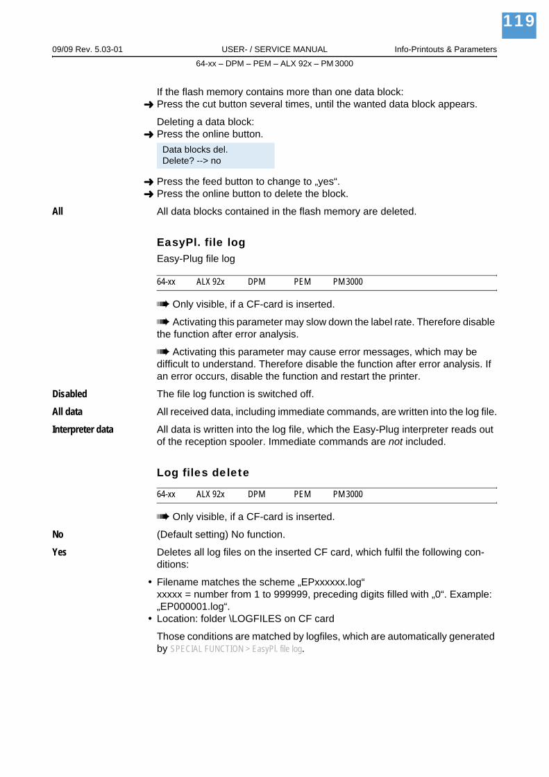
09/09 Rev. 5.03-01 USER- / SERVICE MANUAL Info-Printouts & Parameters
64-xx – DPM – PEM – ALX 92x – PM 3000
119
If the flash memory contains more than one data block:Press the cut button several times, until the wanted data block appears.
Deleting a data block:Press the online button.
Press the feed button to change to „yes“.Press the online button to delete the block.
All All data blocks contained in the flash memory are deleted.
EasyPl. file logEasy-Plug file log
64-xx ALX 92x DPM PEM PM 3000
Only visible, if a CF-card is inserted.
Activating this parameter may slow down the label rate. Therefore disable the function after error analysis.
Activating this parameter may cause error messages, which may be difficult to understand. Therefore disable the function after error analysis. If an error occurs, disable the function and restart the printer.
Disabled The file log function is switched off.
All data All received data, including immediate commands, are written into the log file.
Interpreter data All data is written into the log file, which the Easy-Plug interpreter reads out of the reception spooler. Immediate commands are not included.
Log files delete
64-xx ALX 92x DPM PEM PM 3000
Only visible, if a CF-card is inserted.
No (Default setting) No function.
Yes Deletes all log files on the inserted CF card, which fulfil the following con-ditions:
Filename matches the scheme „EPxxxxxx.log“xxxxx = number from 1 to 999999, preceding digits filled with „0“. Example: „EP000001.log“.Location: folder \LOGFILES on CF card
Those conditions are matched by logfiles, which are automatically generated by SPECIAL FUNCTION > EasyPl. file log.
Data blocks del.Delete? --> no

09/09 Rev. 5.03-01 USER- / SERVICE MANUAL Info-Printouts & Parameters
64-xx – DPM – PEM – ALX 92x – PM 3000
120
RFID stat. del.
64-xx ALX 92x DPM PEM PM 3000
Sets all RFID counters to zero.
See PRINT INFO > RFID status.

09/09 Rev. 5.03-01 USER- / SERVICE MANUAL Info-Printouts & Parameters
64-xx – DPM – PEM – ALX 92x – PM 3000
121
SERVICE FUNCTION
Service
64-xx ALX 92x DPM PEM PM 3000
Parameter only appears in production mode.
Increases the counter level of the "Service" counter on the "Service Status" printout by one.
See parameter Service Status / on page 31.
yes Increases the counter "Services" by one
no Doesn´t increase the counter
Head exchange
64-xx ALX 92x DPM PEM PM 3000
Parameter only appears in production mode.
Increases the counter „Head number“ on the info printout „Service Status“ by one.
See parameter Service Status / on page 31.
yes Increases the counter "Head number" by one
no Doesn´t increase the counter
Roller exchange
64-xx ALX 92x DPM PEM PM 3000
Parameter only appears in production mode.
Increases the counter „Roll number“ on the info printout „Service Status“ by one.
See parameter Service Status / on page 31.
yes Increases the counter "Roll number" by one
no Doesn´t increase the counter

09/09 Rev. 5.03-01 USER- / SERVICE MANUAL Info-Printouts & Parameters
64-xx – DPM – PEM – ALX 92x – PM 3000
122
Cutter exchange
64-xx
Parameter only appears in production mode and only with a cutter mounted and activated.
Increases the counter „Cutter number“ on the info printout „Service Status“ by one.
See parameter Service Status / on page 31.
yes Increases the counter "Cutter number" by one
no Doesn´t increase the counter
Serv. data reset
64-xx ALX 92x DPM PEM PM 3000
Parameter only appears in production mode.
Sets all counters on the info printout „Service Status“ to zero.
See parameter Service Status / on page 31.
Head dot test
64-xx ALX 92x DPM PEM PM 3000
Checks the print head for defective dots. The test ends with a status printout (see Fig. 14), listing the defective dots. The printout is also made without hav-ing found any defective dots.
CAUTION! - Never switch off the printer while the dot check is running! If not observed, dots of the print head can be damaged!
During the test appears the display:
The printout requires 100 mm wide and 200 mm long label material.
Head dot testrunning ...

09/09 Rev. 5.03-01 USER- / SERVICE MANUAL Info-Printouts & Parameters
64-xx – DPM – PEM – ALX 92x – PM 3000
123
[18] Status printout after successfully proceeded dot check. Upper section: technical data of the print head; Lower section: list of defective dots.
The dot check can also be startet by pressing the Cut(Apply)+Feed buttons in Off-line mode. However, in this case is no status report printed.
Head step tune
64-xx ALX 92x DPM PEM PM 3000
Only in production mode.
Fine adjustment of the printhead movement during the ribbon autoeconomy motion.
x step(s) Setting range: -15 to +15; Unit interval: 1; Default setting: 0
EasyPlug monitor
64-xx ALX 92x DPM PEM PM 3000
Parameter only appears in production mode.
The parameter activates the logging of received Easy Plug data. Data is transmitted to COM1 or COM2.
Activating this parameter may slow down the label rate. Therefore disable the function after error analysis.
To keep the influence of the monitoring function on the data rate as low as possible, the baud rate should be set to 115,000!
Disabled (Default setting) The monitor function is disabled.
Serial Com1 The Easy-Plug monitor data is transmitted to Com1.
Serial Com2 The Easy-Plug monitor data is transmitted to Com2.

09/09 Rev. 5.03-01 USER- / SERVICE MANUAL Info-Printouts & Parameters
64-xx – DPM – PEM – ALX 92x – PM 3000
124
EP Monitor Mode
64-xx ALX 92x DPM PEM PM 3000
Parameter only appears in production mode.
Activating this parameter may slow down the label rate. Therefore disable the function after error analysis.
Interpreter data (Default setting) All received Easy-Plug data, apart from immediate com-mands, are transmitted.
All data All received Easy-Plug data, including immediate commands, are trans-mitted.
Head adjust
64-xx ALX 92x DPM PEM PM 3000
Parameter only for authorised, trained service personnel!
Sensor adjust
64-xx ALX 92x DPM PEM PM 3000
Parameter only appears in production mode.
For detailed instructions sensor adjustment, please refer to the service manual, topic section "Service Electronics", paragraph "Settings".
Sensor test
64-xx ALX 92x DPM PEM PM 3000
The description of the sensor test can be found in the printer service manual, topic section „Service Electronics“, chapter Sensor test .
The values displayed are for checking the sensors (sensor check) and can by adjusted by service personnel.
HME registers
64-xx ALX 92x DPM PEM PM 3000
Only in production mode.
64-xx: 64-08 only.
Parameter only for authorised, trained service personnel!
By means of this parameter, the register contents of the HME power supply can be changed.

09/09 Rev. 5.03-01 USER- / SERVICE MANUAL Info-Printouts & Parameters
64-xx – DPM – PEM – ALX 92x – PM 3000
125
Cutter test
64-xx
Makes it possible to test the cutter function without having to set the para-meter SYSTEM PARAMETER > Periph. device to „cutter“.
Press Cut Key Triggers a cut, if a cutter is installed. Without a cutter nothing will happen.
Matend tolerance
64-xx ALX 92x DPM PEM PM 3000 AP 4.4 AP 5.4 AP 7.t
Material end tolerance
This is relevant for label stock with very long punches. To avoid those punch-es being recognized as material end by mistake, can here the distance be set, after which the gap over the light sensor is interpreted as material end.
By choosing a very high material end tolerance, you loose the protection of the print roller against being printed on!
xxx mm Setting range: 20-300 mm; Default setting: 35 mm
Scanner test
64-xx ALX 92x DPM PEM PM 3000
The scanner test is required for the ex-works adjustment of an optional scanner.
On Switches the Scanner-Laser on.
Off Switches the Scanner-Laser off.
Feedadjust label
64-xx ALX 92x DPM PEM PM 3000
Prints a scale, which enables to calculate the feed adjust value (see next parameter).
For application instructions, refer to the Service Manual, topic section „Electronics Gen. 3“, chapter Adjusting the imprint position .

09/09 Rev. 5.03-01 USER- / SERVICE MANUAL Info-Printouts & Parameters
64-xx – DPM – PEM – ALX 92x – PM 3000
126
Feed adjust
64-xx ALX 92x DPM PEM PM 3000
Corrects the material feed length. Such a correction can be necessary when printing on very long labels, to compensate slippage-related feeding inaccu-racy.
For application instructions, refer to the Service Manual, topic section „Electronics Gen. 3“, chapter Adjusting the imprint position .
x.x % Setting range: -10,0 to +10,0; Step width: 0,1%; Default setting: 0%
Foil feed adjust
64-xx ALX 92x DPM PEM PM 3000
Only in production mode.
Modifies the foil feed speed in comparison to the material feed speed.
xx,x % Setting range: -20,0 to 20,0; Default setting: 0,0
Punch y calibr.
64-xx ALX 92x DPM PEM PM 3000
Only in production mode
Compensating the variation of distance between punch sensor and thermal bar of the printhead.
x.x mm Setting range: -3.0 to 3.0; Default setting: 0.0; Unit interval: 0.1
CompactFlashTest
64-xx ALX 92x DPM PEM PM 3000
Test Compact Flash Cards
Pressing the online button starts a test routine for the Compact Flash Card memory. The following display shows up after successful testing:
If the Compact Flash Card is defective or not available, a corresponding error report shows up.
For test purposes, the printer creates a file named TESTXXXX.TXT in the root directory of the card. An already existing file with this name will be over-written.
CompactFlashTestCard Test O.K.

09/09 Rev. 5.03-01 USER- / SERVICE MANUAL Info-Printouts & Parameters
64-xx – DPM – PEM – ALX 92x – PM 3000
127
Send test
64-xx ALX 92x DPM PEM PM 3000
Serial connection
Carrying out the send test requires a terminal program, e.g. the Hyper Termi-nal contained in Windows95.
Start send test as follows:
1. Start the terminal program and set it to the transmission parameters used by the printer.
2. Press the Online-key to start the send test.
[19] Pattern in the terminal window.
The terminal window should show a regular pattern of four repeating charac-ters. Those characters are continuous sent by the printer.
A transfer fault would be recognizable as irregularity of the pattern. Press the Prog-key to stop testing.
Send testrunning . . .

09/09 Rev. 5.03-01 USER- / SERVICE MANUAL Info-Printouts & Parameters
64-xx – DPM – PEM – ALX 92x – PM 3000
128
Parallel connection
The parallel data transfer is done bidirectionally in the Nibble Mode. The transfer test requires an aid program which is available to service engineers.
Receive test
64-xx ALX 92x DPM PEM PM 3000
Serial connection
Assumption is a serial data line between PC and printer; the parameter INTERF.PARAM. > Interface must be set on RS232 or RS485.
1. Start the MS-DOS-window (using Windows).
2. Set the interface to the values adjusted at the printer by means of MS-DOS command MODE:
Example of printer settings:– Baud rate: 19200– No. of data bits: 8– Parity: none– Stop Bits: 1– Data synch.: RTS/CTS
DOS-Command: mode com2 19200 8 n 1(if com2 is the serial port)
3. Press the Online-key to start Receive test.
4. Send any file to the printer (Condition: com2 = Printer port; anyfile.txt = any file ):
copy anyfile.txt com2 (add /b for binary files)
The following shows up on the printer display:
xxxxxx is the size of the sent file in bytes. This value is being counted up dur-ing the test. The test is complete if the file size does not vary any more. If the bytes announced at the printer match the size visible in the MS-DOS window, transfer was successful. Otherwise, transmission errors occurred.
Parallel connection
Assumption is a parallel data line between PC and printer; the parameter INTERF.PARAM. > Interface must be set up on Centronics. Proceed as follows:
1. Run Receive test. To this call the parameter SERVICE FUNCTION > Receive test and press the Online-key.
Receive test0 Bytes
Receive testxxxxx Bytes
Receive test0 Bytes

09/09 Rev. 5.03-01 USER- / SERVICE MANUAL Info-Printouts & Parameters
64-xx – DPM – PEM – ALX 92x – PM 3000
129
2. Start the MS-DOS-window (using Windows).
3. Send any file to the printer (Condition: lpt1 = printer port; anyfile.txt = any file):
copy anyfile.txt lpt1 (add /b for binary files)
The following shows up on the printer display:
xxxxxx is the size of the sent file in bytes. This value is being counted up dur-ing the test. The test is complete if the file size does not vary any more. If the bytes announced at the printer match the size visible in the MS-DOS window, transfer was successful. Otherwise, transmission errors occurred.
Rewinder adjust
64-xx ALX 92x
64-xx: Only with „Rewinder 2000“ installed.
ALX 92x: Only valid for backing paper rewinder.
Setting up the rewinder.
The rewinder setup compensates differeces in characteristic or assembly of the light barrier.
A setting description for the 64-xx rewinder option is given in the „Manual Rewinder 2000“, paragraph Adjusting the sensor .
A setting description for the dancer arm of the ALX 92x backing paper rewin-der can be found in the Service Manual, topic section „Service Electronics“, paragraph Light sensor rewinder dancer arm (ALX) .
Resting pos.xxx Setup of the resting position (xxx = actual sensor value).
End pos. xxx Setup of the End position (xxx = actual sensor value).
The setting follows in both cases this scheme:
1. Bring the dancer arm to its resting position.
2. Press the cut button (ALX 92x: Apply button)
Not the Online button (as with TTX x50)!
3. Bring the dancer arm to its end position.
4. Press the Online button.
Receive testxxxxx Bytes

09/09 Rev. 5.03-01 USER- / SERVICE MANUAL Info-Printouts & Parameters
64-xx – DPM – PEM – ALX 92x – PM 3000
130
Com2 commun. test
64-xx ALX 92x DPM PEM PM 3000
64-xx/ALX 92x/DPM/PEM/PM 3000: Only with installed options board.
After calling this parameter, Com2 puts out all data which are received by the set Easy Plug port.
See parameter Interface / on page 51.If this parameter is set to RS232, data can also be sent in reverse direction (that is, reception by Com2, output by Com1).
Com2 port test
64-xx ALX 92x DPM PEM PM 3000
64-xx/ALX 92x/DPM/PEM/PM 3000: Only with installed options board.
Starts a selftest of the Com2 port.
Only works with RS 232.
Pins 2/3 and 7/8 at the interface have to be connected (use a plug with shunted pins)!
During the selftest, data transfer and handshake are tested. The test ends with one of the following display messages:
Headvo. adj. 20 V
64-xx
Not valid for 64-08.Only in production mode.
Adjusting the lower head voltage limit to 20 V. The head voltage adjustment makes printouts comparable.
For details about adjusting the printhead voltage, refer to the Service Manual, topic section "Service print module", paragraph "Adjusting the printhead voltage".
Com2 port testTest failed
An error has occured while testing the interface.
Com2 port testTest O.K.
Interface test successfully terminated.

09/09 Rev. 5.03-01 USER- / SERVICE MANUAL Info-Printouts & Parameters
64-xx – DPM – PEM – ALX 92x – PM 3000
131
Headvo. adj. 28 V
64-xx
Not valid for 64-08.Only in production mode.
Adjusting the upper head voltage limit to 28 V. The head voltage adjustment makes printouts comparable.
For details about adjusting the printhead voltage, refer to the Service Manual, topic section "Service print module", paragraph "Adjusting the printhead voltage".
Printtest
64-xx ALX 92x DPM PEM PM 3000
General printtest, prints line by line the set printer type and the firmware ver-sion. Material settings (Material type, length, width) are considered.
Stop the printtest by pressing the Online button.

09/09 Rev. 5.03-01 USER- / SERVICE MANUAL Info-Printouts & Parameters
64-xx – DPM – PEM – ALX 92x – PM 3000
132
SERVICE DATA
> MODULE FW VERS.
System version
64-xx ALX 92x DPM PEM PM 3000
Shows the firmware version number.
System revision
64-xx ALX 92x DPM PEM PM 3000
Shows a consecutive revision number.
Only for factory-internal use.
System date
64-xx ALX 92x DPM PEM PM 3000
Shows the date, at which the firmware was generated.
Bootloader
64-xx ALX 92x DPM PEM PM 3000
Shows the bootloader version number.
uMon
64-xx ALX 92x DPM PEM PM 3000
Shows the bootloader version number.
Feed driver
64-xx ALX 92x DPM PEM PM 3000
Applied PIC version on the output stage board driving the feed motor.
Foil driver
64-xx ALX 92x DPM PEM PM 3000
Applied PIC version on the output stage board driving the foil feed motor.
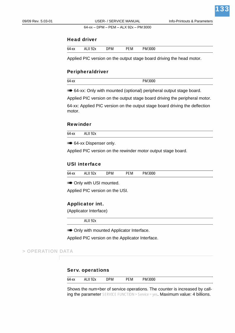
09/09 Rev. 5.03-01 USER- / SERVICE MANUAL Info-Printouts & Parameters
64-xx – DPM – PEM – ALX 92x – PM 3000
133
Head driver
64-xx ALX 92x DPM PEM PM 3000
Applied PIC version on the output stage board driving the head motor.
Peripheraldriver
64-xx PM 3000
64-xx: Only with mounted (optional) peripheral output stage board.
Applied PIC version on the output stage board driving the peripheral motor.
64-xx: Applied PIC version on the output stage board driving the deflection motor.
Rewinder
64-xx ALX 92x
64-xx Dispenser only.
Applied PIC version on the rewinder motor output stage board.
USI interface
64-xx ALX 92x DPM PEM PM 3000
Only with USI mounted.
Applied PIC version on the USI.
Applicator int.(Applicator Interface)
ALX 92x
Only with mounted Applicator Interface.
Applied PIC version on the Applicator Interface.
> OPERATION DATA
Serv. operations
64-xx ALX 92x DPM PEM PM 3000
Shows the num+ber of service operations. The counter is increased by call-ing the parameter SERVICE FUNCTION > Service = yes. Maximum value: 4 billions.

09/09 Rev. 5.03-01 USER- / SERVICE MANUAL Info-Printouts & Parameters
64-xx – DPM – PEM – ALX 92x – PM 3000
134
Headnumber
64-xx ALX 92x DPM PEM PM 3000
Shows the number of printhead changes. The counter is increased by calling the parameter SERVICE FUNCTION > Cutter exchange = yes. Maximum value: 4 bil-lions.
Roll number
64-xx ALX 92x DPM PEM PM 3000
Shows the number of exchanged print rollers. The counter is increased by calling the parameter SERVICE FUNCTION > Roller exchange > yes. Maximum value: 4 billions.
Cutter number
64-xx PM 3000
Only with mounted and activated cutter.
Shows the number of exchanged cutters. The counter is increased by calling the parameter SERVICE FUNCTION > Cutter exchange =yes. Maximum value: 4 billions.
Head run length
64-xx ALX 92x DPM PEM PM 3000
Shows the total "covered distance" of the printhead. The counter is reset with each calling of the parameter SERVICE FUNCTION > Cutter exchange = yes. Maximum value: 4 billions.
Roll run length
64-xx ALX 92x DPM PEM PM 3000
Shows the total "covered distance" of the print roller. The counter is reset with each calling of the parameter SERVICE FUNCTION > Roller exchange = yes. Maximum value: 4 billions.
Cuts on knife
64-xx PM 3000
Only with mounted and activated cutter.
Shows the number of cuts done by one knife. The counter is reset with each calling of the parameter SERVICE FUNCTION > Cutter exchange = yes. Maximum value: 4 billions.

09/09 Rev. 5.03-01 USER- / SERVICE MANUAL Info-Printouts & Parameters
64-xx – DPM – PEM – ALX 92x – PM 3000
135
Tot. mat. length
64-xx ALX 92x DPM PEM PM 3000
Shows the total "covered distance" of the feed roller. In comparison to the counter Roll run length, this counter is not reset after a roller exchange. Max-imum value: 4 billions.
Tot. foil length
64-xx ALX 92x DPM PEM PM 3000
Shows the total "covered distance" of the ribbon roller.
Total cuts
64-xx PM 3000
Only with mounted and activated cutter.
Shows the number of cuts done by all knifes. In comparison to the counter Cuts on knife, this counter is not reset after a knife exchange. Maximum val-ue: 4 billions.
Total head moves
64-xx ALX 92x DPM PEM PM 3000
Only with mounted and activated cutter.
Shows the counter for every up and down movement of the printhead. Maxi-mum value: 4 billions.
Head strobes
64-xx ALX 92x DPM PEM PM 3000
Shows the counted head strobes, which are a measure for the service life of the printhead. A strobe is counted for each line in which at least one dot ist printed. Maximum value: 4 billions.
Head temperature
64-xx ALX 92x DPM PEM PM 3000
Shows the current printhead temperature in °C.

09/09 Rev. 5.03-01 USER- / SERVICE MANUAL Info-Printouts & Parameters
64-xx – DPM – PEM – ALX 92x – PM 3000
136
Foil diameter
64-xx ALX 92x DPM PEM PM 3000
Shows the calculated foil diameter: A measurement routine calculates the ac-tual ribbon roll diameter with an exactness of 7.5%.
The parameter SYSTEM PARAMETER > Foil end warning can be used to set a critical foil roll diameter. If the foil roll diameter equals this value, a message appears on the printer display.
See parameter Foil end warning / on page 71.64-xx, DPM / PEM, ALX 92x:At the (optional) USI is set a signal indicating the near foil end (additionally to the display warning).
Dispensing cycl.(Dispensing cycles)
64-xx ALX 92x DPM
64-xx/AP 5.4: Dispenser version only.
Shows the number of dispensed labels.
Operation time
64-xx ALX 92x DPM PEM PM 3000
Shows the elapsed time since the last switch-on of the machine.

09/09 Rev. 5.03-01 USER- / SERVICE MANUAL Info-Printouts & Parameters
64-xx – DPM – PEM – ALX 92x – PM 3000
137
> POWERSUPPLYDATA
Type
64-xx ALX 92x DPM PEM PM 3000
Shows the type of power supply, e.g. „Blue Mountain“.
PS temperature
64-xx ALX 92x DPM PEM PM 3000
Shows the current power supply temperature in °C. If for any reason the func-tion is not supported, „??? °C“ is displayed.
Version
64-xx ALX 92x DPM PEM PM 3000
Availability depends on the type of power supply.
Shows the power supply version.
Serial number
64-xx ALX 92x DPM PEM PM 3000
Availability depends on the type of power supply.
Shows the power supply serial number.
Standby+On time
64-xx ALX 92x DPM PEM PM 3000
Availability depends on the type of power supply.
Shows the power supply operation time including the standby time.
Standby time is the duration of time, during which the printer was switched on with the power switch, but not with the remote on/off switch on the operation panel.
Doesn´t count for 64-xx. At the 64-xx, the same time as under SERVICE DATA > POWERSUPPLY DATA > On time
The operation time tells nothing about the printing time of the printer.
09/09 Rev. 5.03-01 USER- / SERVICE MANUAL Info-Printouts & Parameters
64-xx – DPM – PEM – ALX 92x – PM 3000
138
On time
64-xx ALX 92x DPM PEM PM 3000
Availability depends on the type of power supply.
Shows the operation time of the printer. This does not comprise the standby time (see SERVICE DATA > POWERSUPPLY DATA > Standby+On time).
The operation time tells nothing about the printing time of the printer.
> CPU BOARD DATA
CPU identifier
64-xx ALX 92x DPM PEM PM 3000
Shows the designation of the applied processor.
PCB revision
64-xx ALX 92x DPM PEM PM 3000
Shows the layout revision and part number of the CPU board.
FPGA version
64-xx ALX 92x DPM PEM PM 3000
Shows the FPGA version.
MAC address
64-xx ALX 92x DPM PEM PM 3000
Shows the MAC Address, an unchanging board address, which is pro-grammed by the board manufacturer.
Serial number
64-xx ALX 92x DPM PEM PM 3000
Serial number: Is programmed by the board manufacturer.
Production date
64-xx ALX 92x DPM PEM PM 3000
Production date: Is programmed by the board manufacturer.

09/09 Rev. 5.03-01 USER- / SERVICE MANUAL Info-Printouts & Parameters
64-xx – DPM – PEM – ALX 92x – PM 3000
139
PCB part number
64-xx ALX 92x DPM PEM PM 3000
Shows the part number of the board without components.
Board part numb.
64-xx ALX 92x DPM PEM PM 3000
Shows the part number of the board with components.
Manufacturer
64-xx ALX 92x DPM PEM PM 3000
Parameter appears only in production mode.
Shows the board manufacturer.
Work place
64-xx ALX 92x DPM PEM PM 3000
Parameter appears only in production mode.
Shows the printer work place.
Company name
64-xx ALX 92x DPM PEM PM 3000
Parameter appears only in production mode.
Shows the company name.
> DISPLAY DATA
Display version
64-xx ALX 92x DPM PEM PM 3000
Shows the version number of the operation panel.
Display SerialNr
64-xx ALX 92x DPM PEM PM 3000
Shows the serial number of the operation panel.

09/09 Rev. 5.03-01 USER- / SERVICE MANUAL Info-Printouts & Parameters
64-xx – DPM – PEM – ALX 92x – PM 3000
140
Remote disp. vers.
64-xx ALX 92x DPM PEM PM 3000
Only if remote operation panel is connected.
Shows the version number of the remote operation panel.
Remote disp. #
64-xx ALX 92x DPM PEM PM 3000
Only if remote operation panel is connected.
Shows the serial number of the remote operation panel.
> MEMORY DATA
Ram memory size
64-xx ALX 92x DPM PEM PM 3000
Shows the available RAM memory size.
Flash mem size
64-xx ALX 92x DPM PEM PM 3000
Shows the available Flash memory size. The abbreviation which is displayed behind the memory size indicates the manufacturer of the applied Flash-RAM:
Abbreviation ManufacturerMX MacronixAMD AMDFUJ Fuji
[15] The displayed abbreviations indicate the manufacturer of the Flash-RAM.

09/09 Rev. 5.03-01 USER- / SERVICE MANUAL Info-Printouts & Parameters
64-xx – DPM – PEM – ALX 92x – PM 3000
141
CompactFlash
64-xx ALX 92x DPM PEM PM 3000
Only with plugged-in CF card.
Shows the memory size of the CF card.
Space for Jobs
64-xx ALX 92x DPM PEM PM 3000
Shows the memory size, which is available for print jobs.
Max. Labellength
64-xx ALX 92x DPM PEM PM 3000
Shows the maximum printable label length, which results from the memory allocation.
Default values
64-xx ALX 92x DPM PEM PM 3000
Shows the setting of parameter SPECIAL FUNCTION > Default values.