axis4000 anleitung deutsch
TRANSCRIPT

INSHDC40GB REV: 10/16
WIRELESS FRAME MEASUREMENT BY RADIO SYSTEM TRANSMISSION
HDC40
INSTRUCTIONS MANUAL (Original instructions)

HDC40
2
INDEX
Page Nr.
I. WARNINGS – SAFETY INSTRUCTIONS 3 II. HDC40 HANDLING AND STORAGE 4 III. PRODUCT DESCRIPTION 4 - 6 IV. EQUIPMENT PROVIDED 7 - 8 V. SET-UP 9 - 13 VI. THE HDC40 PROGRAM 14 - 18 VII. PREPARING FOR MEASUREMENT 19 - 21 VIII. FRAME ALIGNMENT 22 - 24 IX. VIEWING THE MEASUREMENTS 25 X. ADJUSTING THE VEHICLE FRAME 26 XI. PROTOCOL, VEHICLE OVERVIEW 27 XII. SERVICING 28 XIII. ERROR DESCRIPTION 29 XIV. APPENDIX 30 XV. DECLARATION OF CONFORMITY 31

HDC40
3
1 WARNINGS – SAFETY INSTRUCTIONS
1.1 Operator’s duty of care
The electronic camera radio system HDC40 has been designed and constructed in accordance with a thorough selection of applicable harmonised standards. Hence, it corresponds to the current state of technology and offers the highest degree of safety during operation.
The components of the HDC40 may only be structurally modified by the manufacturer with written authorization. Device safety can only be implemented in practice during operation if all the required applicable measures have been taken. The operator’s duty of care includes planning such measures and checking that they have been implemented.
In particular, the operator must ensure that:
the device is only used for its intended purpose
the device is only used in a fully functioning state and free from defects
the complete operating instructions are permanently available in a readable condition at the operating location of the device
only qualified and authorised personnel who are familiar with these operating instructions and can work in accordance with these instructions operate the device!
personnel are regularly instructed in all relevant work safety issues and are familiar with the operating instructions, in particular the safety instructions.
Prior to each use of the frame measuring system, the system must be checked for visible damage, and it must be ensured that the device is only operated free from defects. Defects that are identified must be reported to your superior immediately.
CAUTION:
The user is personally responsible for proper operation and compliance with safety regulations.

HDC40
4
2 HDC40 HANDLING AND STORAGE
CAUTION: Severe shocks must be avoided during transport.
The system must be protected against moisture at all times.
This applies in particular during transport and storage of the entire electronic camera radio system. Care should be taken to ensure that the storage location is dry and dust-free.
Always store the camera charged.
3 PRODUCT DESCRIPTION
HDC40 Frame measuring device

HDC40
5
Authorised intended use
The frame measuring device HDC40 has been developed in order to measure the vehicle frames on trucks, trailers and semi-trailers.
It is designed solely for rapid measurement of the vehicle frame.
The following is recorded on the vehicle frame:
- the lateral frame deformation = horizontal deviations - the height difference of the frame = vertical deviation - the torsion of the frame
The frame measuring device HDC40 allows you to measure in “driving position”, i.e. the vehicle does not have to be raised.
CAUTION:
If the frame measuring device HDC40 is not used as per this intended use, there is no guarantee that operating the device will be safe.
The operator of the frame measuring device, and not the manufacturer, shall be liable for all damage to persons and property caused by incorrect use.

HDC40
6
3.1 Technical data
Measuring range Measuring accuracy:
Horizontal frame offset 0 - 750 mm ± 0.5 mm
Vertical frame offset 0 - 750 mm ± 0.5 mm
Frame torsion -18 degrees to +18 degrees ± 0°05’
Measurable max. frame length up to 18 metres --
Measurable max. frame width 750 - 1,350 mm -- Operating temperature -5 to +40 degrees Celsius Operating time with fully charged battery > 10 h Shock resistance of the sensor 3500 g (inclinometer) 2000 g (gyro) Radio module: Band 433.05 to 434.79 MHz Automatic frequency correction Number of channels 10 Transmission power 10 mW Battery charger: Operating voltage 100 - 240 Volts
PC system requirements for HDC40
Required operating system: Windows XP, Vista, Win 7, Win 8.1 Minimum hardware requirements:
Processor: Pentium IV – AMD Athlon 1 GHz RAM: 512 MB (Windows XP) / 2048 MB (Windows Vista, Win 7, Win 8.1) 60 MB available hard disk space Graphics: 1024 x 768 pixel resolution / High Colour Sound card Port: USB 1.1 CD-ROM drive Recommended:
Processor: 1.6 GHz Pentium or AMD or better RAM: 2048 MB Graphic card with 16 MB AMD (ATI) or NVIDIA chipset or better 1280 x 1024 pixel resolution / True Colour Printer

HDC40
7
4 EQUIPMENT PROVIDED
4.1 Parts List – HDC40 Basic version
1 Radio camera Item No. HDL4001
1 Transmission / receiver unit Item No. HDL4006
1 0.5 m USB cable for radio receiver 65 Item No. HDL4004
1 Camera charging station Item No. HDL4003
1 Frame scale Item No. HDC401

HDC40
8
1 Camera holder Item No. HDC403
1 Adjustable foot support Item No. HDC410
2 620mm Aluminium extensions for camera Item No. HDC411
1 CD Rom + 512 MB USB stick 1 Instructions manual Item No. HDC404 Item No. INSHDC40GB
4.2 Optional accessories HDC40
100 mm extensions (Pair) 150 mm extensions (Pair) Item No. HDC406 Item No. HDC407
Please contact your sales representative for additional accessories.

HDC40
9
5 SET-UP
On first use of the HDC40, the following must be carried out: Assembly of the HDC40 components Installation of the software and the FM transmitter in Windows Software setup
5.1 Assembling the camera stand
Camera guide tube
Telescopic foot stand

HDC40
10
The camera guide tube is inserted vertically into the foot stand and locked in
place.
The 4 telescopic tubes are extended and locked in place using the wing
nuts.
Mount the camera onto the camera stand mounting pin.
(see page 21)

HDC40
11
5.2 Assembling the frame scale
Frame scale with attachment bars.
Unscrew the ends of the attachment bars.
Guide the attachment bars through the scale and screw them back together.
Fix the attachment bars in place with the clamping screws. (also see 7.1)

HDC40
12
5.3 Installing the software in Windows
Close all open applications on the computer.
Insert the CD into the CD-ROM drive.
If the installation wizard does not start automatically, click “Start” on the Windows taskbar, then “Run”. Enter D:\ CMC4000Nsetup_0.01.012.exe, where D is the drive letter of the CD-ROM drive.
Confirm the Windows security warning if necessary and
click “Run”.
Read the licence agreement and follow the instructions of the installation wizard on screen. (Fig. 2)
Select the components to be installed (Fig. 3)
When the installation procedure has completed, the software and the driver for the FM transmitter have been installed on the computer.
Remove the CD from the CD-ROM drive after installation.
The driver for the FM transmitter is normally automatically installed on the system on your computer when the program is installed. When the FM transmitter is connected to a free USB port on the PC after installation, the new hardware is recognised and added to the system. If this does not take place automatically, or if you uninstall and want to reinstall the driver manually, the driver can be added to your system again as following.
5.4 Installing the FM transmitter
Connect the transmission and receiver unit (the FM transmitter) to a free USB port on the computer using the enclosed USB connection cable (Fig. 4) and insert the CD.
The new hardware is recognised by Windows, and the installation wizard searches for the appropriate driver.
(Fig. 4)
(Fig. 1)
(Fig. 2)
(Fig. 3)
HDC40
13
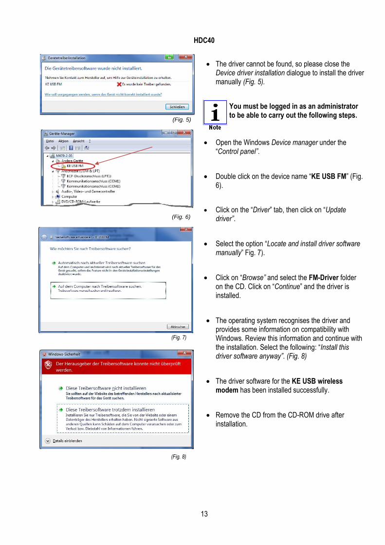
The driver cannot be found, so please close the Device driver installation dialogue to install the driver manually (Fig. 5).
You must be logged in as an administrator to be able to carry out the following steps.
Open the Windows Device manager under the “Control panel”.
Double click on the device name “KE USB FM” (Fig. 6).
Click on the “Driver” tab, then click on “Update driver”.
Select the option “Locate and install driver software manually” Fig. 7).
Click on “Browse” and select the FM-Driver folder on the CD. Click on “Continue” and the driver is installed.
The operating system recognises the driver and provides some information on compatibility with Windows. Review this information and continue with the installation. Select the following: “Install this driver software anyway”. (Fig. 8)
The driver software for the KE USB wireless modem has been installed successfully.
Remove the CD from the CD-ROM drive after installation.
(Fig. 5)
(Fig. 7)
(Fig. 6)
(Fig. 8)

HDC40
14
6 THE HDC40 PROGRAM
We have taken great care to ensure that the entire program is straightforward and clear so that the user can monitor and operate the device at all times with ease.
Help text and graphical illustrations introduce you to the different parts of the program and provide information about the program at all times.
6.1 Setting up the software
Start the Program. Select the icon on desk.
When the program has started, select the “Settings” option for initial basic setup

HDC40
15
6.2 Overview of the program settings
6.2.1 Customer data:
Enter your company name on the applicable lines so that the name can be included and printed on the measurement protocol. (Fig. 9) Click on the “Select image” button: A company logo can be saved, which will be displayed on the protocol. Supported file types: BMP, JPG, GIF, PNG The image size is scaled.
Image files that are too small are enlarged and their quality is therefore reduced. The smallest format should be 400 x 200 pixels at 72 dpi.
6.2.2 Language:
Click on the “Select Language” button to display menus and all instructions in another (approved) language (Fig. 10)
All settings must be confirmed by clicking the “Save” button.
(Fig. 10)
*

HDC40
16
6.2.3 Interface:
After successful installation, a new virtual COM interface has been added to the computer for communication with the FM transmitter. The interface setting in the program should be set to AUTO for an automatic connection. The interface may be changed manually to a specific port if required (no connection to the camera).
A new entry has been added to the Windows device manager for the new FM transmitter COM interface (KE USB wireless modem). (Fig. 11)
Radio channel: The radio channel set on the camera is automatically displayed for data transfer between the camera sensor and the program. The radio channel may be changed on the camera if necessary and must then be confirmed by clicking the “Magnifier” button. “Magnifier” button The dialogue window is divided into two columns. The left column displays a camera that has been found by the program, but is not yet connected. The right column displays a camera that is already connected to the program by radio.
The camera and the FM transmitter must be set to the same radio channel.
Serial number: The camera’s serial number is displayed as soon as the program has established a connection with the camera. 6.2.4 Camera symbol information:
During the entire program run, the connection to the camera and the battery charge status are constantly checked and displayed. Description of symbols: Connection problem between the software and the cameras; status unknown. (Fig. 13) The display flashes yellow and red alternately. The program is attempting to establish a connection with the camera. (Fig. 14)
(Fig. 11)
(Fig. 13)
(Fig. 14)
(Fig. 12)

HDC40
17
Display is green: Connection to the camera has been established. (Fig. 15) Display is green, with a red centre: Connection has been established, but no reflector has been found. (Fig. 16) Display is green, with a yellow centre: Connection has been established and the reflectors on the frame scale have been recognised. (Fig. 17) Battery charge status of the camera 100 %, 75 %, 50 %, < 25 % of capacity (Fig. 18) At a battery charge status below 25%, the camera symbol flashes. (Fig. 19)
CAUTION: The camera must be charged before any further measurements. 6.2.5 Instructions
Specifying the default for displaying/hiding operating instructions during measurements. (Fig. 20)
The instructions window can be displayed/hidden at any point in the program. Click on the “Instructions” button on the program page.
6.2.6 Data directory
All vehicle measurements are saved in a protocol file. The preset save path in WINDOWS XP is: My_Documents\Username\Application_Data\Haweka\ CMC4000N\Database. In WINDOWS 7, the preset path is: C:\Users\xx-User-xx\AppData\ Roaming\Haweka\CMC4000N\Database (Fig. 22)
(Fig. 15)
(Fig. 16)
(Fig. 17)
(Fig. 18)
(Fig. 19)
(Fig. 20)
(Fig. 22)
(Fig. 21)

HDC40
18
To change the save location, click on the “Folder” button: To reset the default path, click on the “Reset” button: 6.2.7 Advanced settings
Under advanced settings, the user has the option of personalising the program. (Fig. 23) To customise settings, select the applicable parameter on the table and change the value. The modified entries must be confirmed by clicking the “Accept values” button (Fig. 24). 6.2.8 Password
This function is used by our service personnel to carry out diagnostics on the system. This option allows our service personnel to test special functions and implement program-specific changes. (Fig. 25) 6.2.9 System overview
The system overview provides a list of the components used, the PC, the camera, the FM transmitter and the program versions. This information is used by the service technician in the event of errors as an overview of the system. (Fig. 26)
(Fig. 23)
(Fig. 26)
(Fig. 24)
(Fig. 25)

HDC40
19
7 PREPARING FOR MEASUREMENT
Before measurement can begin, the measurement area and the vehicle must be prepared.
The following preconditions must be observed:
Check that the vehicle has rims and tires of the same size.
Check that the tire pressure is correct.
Check the condition of the suspension and shock absorbers.
The floor of the area used for measurement should not be uneven.
The measurement points on the frame must be freely accessible.
If necessary, the attachment parts on the frame (e.g. spare wheel brackets, tool boxes etc.) must be removed.

HDC40
20
7.1 Preparatory Measures
Park the vehicle on level ground.
Use the attachment bars to set the frame scale bars to a length such that visual contact is guaranteed between the frame scale and camera throughout measurement (Fig. 27)
Position the camera stand to the centre rear of the vehicle and suspend the frame scale at the rear end of the frame. (Fig. 28)
Pull out the four telescopic tubes and lock them in place. (Fig. 29)
Care must be taken to ensure that the camera has free visual contact of the frame scale.
CAUTION: The length of the frame scale attachment bars must not be altered during measurement.
Attaching the camera
Pull the camera’s mounting bolt gently upwards, and slide the camera onto the camera mounting pin until the mounting bolt locks into the groove on the mounting pin.
Then, fix the camera to the pin by gently tightening the mounting bolt. (Fig. 30)
(Fig. 27)
(Fig. 28)
(Fig. 29)
(Fig. 30)

HDC40
21
Frame scale
The frame scale is suspended at the end of the vehicle frame.
The frame scale width must be adjusted to the vehicle frame width.
The scale width is adjusted synchronously. Hence, the frame scale is always located at the centre of the vehicle frame.
The frame scale is fitted to the frame profile. If necessary, the frame scale can be attached to the frame profile with the two knurled nuts.(Fig. 33)
The frame scale should be at a right angle to the frame, as far as possible. (Fig. 34)
(Fig. 31)
(Fig. 34)
(Fig. 32)
(Fig. 33)
HDC40
22
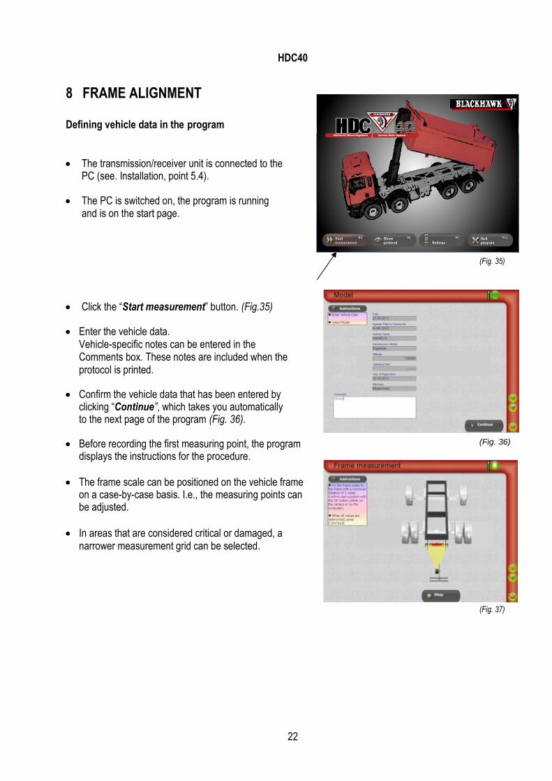
8 FRAME ALIGNMENT
Defining vehicle data in the program
The transmission/receiver unit is connected to the PC (see. Installation, point 5.4).
The PC is switched on, the program is running and is on the start page.
Click the “Start measurement” button. (Fig.35)
Enter the vehicle data. Vehicle-specific notes can be entered in the Comments box. These notes are included when the protocol is printed.
Confirm the vehicle data that has been entered by clicking “Continue”, which takes you automatically to the next page of the program (Fig. 36).
Before recording the first measuring point, the program displays the instructions for the procedure.
The frame scale can be positioned on the vehicle frame on a case-by-case basis. I.e., the measuring points can be adjusted.
In areas that are considered critical or damaged, a narrower measurement grid can be selected.
(Fig. 37)
(Fig. 35)
(Fig. 36)

HDC40
23
8.1 Recording measurements
Once preparations have been completed, the first measuring point can be recorded in the program by clicking the “OK” button.
Put the frame scale at a new position on the vehicle frame and click the “Ok” button to record the next measurement. (Fig. 38)
Mark the position of each measuring point on the frame with a chalk line.
Depending on the distance between measuring points and depending on the frame length, the Z-axis of the graph is automatically extended. (Fig. 39 + 40)
Once all measuring points have been recorded, click on “Continue”.
(Fig. 38)

HDC40
24
8.2 Sorting measurements
To evaluate measurements, a reference area must be selected on the vehicle frame. I.e., an undamaged area is marked on the vehicle frame and used as a reference for the calculations.
This area is defined between two points (green), which indicate the beginning and end of the reference area. All points between are automatically selected. (Fig. 41)
The marked area can start and end at any point and must not necessarily be at the beginning or end of the frame.
You can delete a chosen point using the right mouse button.
At least two points must be chosen on the vehicle frame.
Once you have made your selection, click on the “Recalculate positions” button.
The program identifies the reference plane and centres the frame graphically to the centre of the vehicle. (Fig. 42)
Click on “Continue” to display the measurement results.
(Fig.41 )
(Fig.42 )

HDC40
25
9 VIEWING THE MEASUREMENTS
The measurements of the vehicle frame are displayed on a chart. It is possible to customise what measurements are displayed or hidden on the chart, as the program has a large number of display options.
Click on the “View options” button (Fig. 43) to select different displays. Select one or more view options as required.
Select different displays (Fig. 44) and print with each setting.
Simplified 3D display showing key measurements (Fig. 45) Display with all measurements, including reference lines. (Fig. 46) Click on the “Print” button (Fig. 47) to print out the different displays on an installed printer, as a protocol.
(Fig. 47)
(Fig. 43)
(Fig. 44)
(Fig. 45)
(Fig. 46)

HDC40
26
10 ALIGNING THE VEHICLE FRAME
CAUTION: This part of the program only provides assistance during straightening. It is always necessary to repeat frame measurement after repairs.
Click on the “Adjust frame” button to straighten the
vehicle frame. (Fig. 48) Please note that the data must be carefully evaluated prior to straightening. Specialist tools are no less important in terms of straightening the vehicle frame than your eyes and ears and technical competence.
When straightened, the vehicle frame undergoes plastic deformation. The deformation behaviour depends, among other things, on the existing state of stress, the temperature, the type of load and the load rate. Ask the manufacturer for further information on the type and scope of possible work.
The live image on the display shows the frame values for the height difference and the deviation from the centre of the vehicle at the location of the frame scale on the vehicle frame. (Fig. 49)
During straightening, the frame scale must be fixed to the vehicle frame with the knurled screws. (Fig. 50)
Correction of the vehicle frame can be observed directly on the monitor.
Ideally, the left and right values should be adjusted to the same value. This applies to both the height difference and the lateral deformation from the centre of the vehicle. (Fig. 51)
When the work has been completed, the vehicle frame must be remeasured. Click on the Continue button to complete this procedure
Save this measurement and repeat the measurement process.
(Fig. 50)
(Fig. 49)
(Fig. 51)
(Fig. 48)

HDC40
27
11 PROTOCOL, VEHICLE OVERVIEW
Click the “Show protocol” button on the start page of the program to reopen a saved measurement session. (Fig. 52)
A list of all saved measurement sessions with basic information is displayed when you click “Show protocol”. (Fig. 53) Clicking on the “Show” button displays the selected dataset from a frame alignment session on the overview page, where the view options can also be modified.
(Fig. 53)
(Fig. 52)

HDC40
28
12 SERVICING
12.1 Maintenance and care The frame scale and camera must be kept free of dirt at all times.
Please note that the camera and its accessories are precision components. These components must be used and maintained with great care at all times.
CAUTION :
The protective screen in front of the camera lens must be cleaned with a dry, soft cloth, if necessary. Never clean the lens with alcohol or other liquids.
Care must be taken to ensure that the reflectors on the frame scale are not scratched. Scratched reflectors may cause errors when measurements are recorded.
Only use the supplied battery charger to charge the battery in the camera measuring head. The charger conforms to European safety standards and has been designed specifically for use with the HDC40.

HDC40
29
13 ERROR DESCRIPTION
CAUTION:
Operators may only correct errors that are clearly the result of errors during operation or maintenance.
13.1 Description and causes of errors
Description Possible causes Correction of error
The program has started, but there is no connection with the camera
There is insufficient battery power
Incorrect interface connection specified in the program
No or incorrect radio channel for the camera connection.
No USB driver installed for the receiver on the operating system.
Charge the batteries in the camera measuring head with the battery charger provided.
After the program has started, click on “Settings”; the interface should be set to AUTO (see 6.2.3)
Try to establish a new connection over a different radio channel.
Install the USB driver from the CD provided. (point 5.4, page 13).
The camera does not detect a signal.
The reflectors are badly damaged or dirty.
The camera does not have a clear view of the reflectors.
Clean the reflectors, or replace with new reflectors, if necessary.
Align the frame scale and camera stand with one another. If this occurs during a measurement, the measurement process must be restarted.

HDC40
30
14 APPENDIX
14.1 Example measurement protocol for vehicle frame alignment.

HDC40
31
15 DECLARATION OF CONFORMITY

HDL40
32
BLACKHAWK SAS
All rights reserved International Sales
BP 5 – 67026 Strasbourg Cedex - FRANCE Tel: +33 3 88 65 76 30 – Fax: +33 3 88 65 76 31
E-Mail : [email protected] - www.blackhawk.fr
France – Benelux
BP 5 – 67026 Strasbourg Cedex – FRANCE Tel: 03 88 65 76 30 – Fax: 03 88 65 76 31 E-Mail : [email protected] / [email protected]
www.blackhawk.fr
Deutschland – Schweiz - Österreich
BP 5 – 67026 Strasbourg Cedex – FRANCE Tel: +33 3 88 65 76 30 – Fax: +33 3 88 65 76 31
E-Mail : [email protected] - www.blackhawk.fr