axs-100 access otdr - bcc solutions
TRANSCRIPT
SP
EC
SH
EE
T
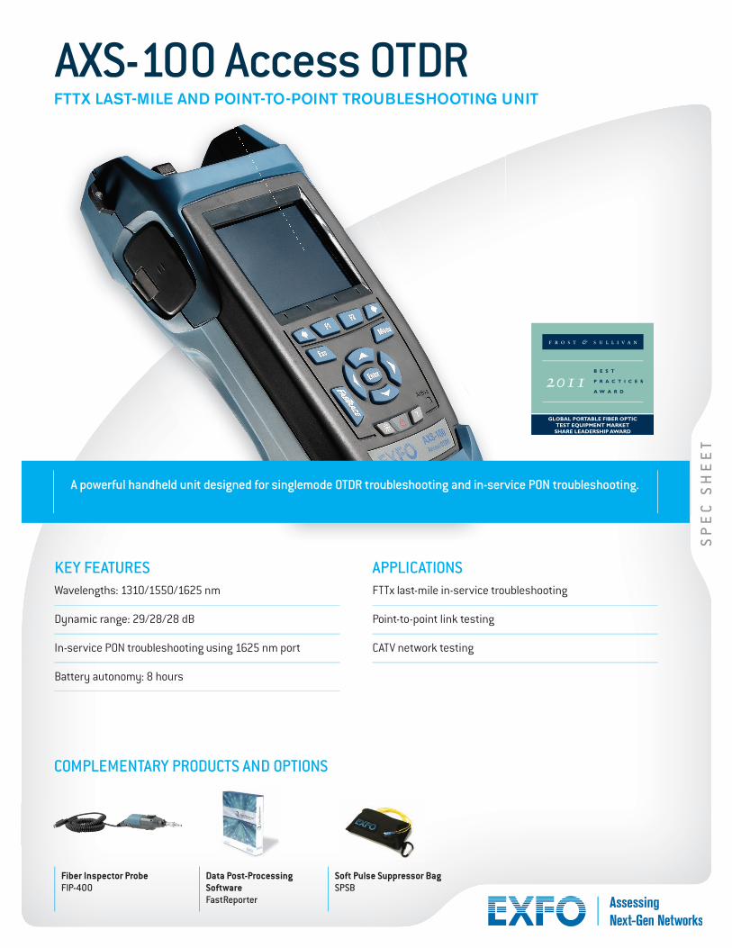
A powerful handheld unit designed for singlemode OTDR troubleshooting and in-service PON troubleshooting.
Fiber Inspector ProbeFIP-400
Data Post-Processing SoftwareFastReporter
Soft Pulse Suppressor BagSPSB
COMPLEMENTARY PRODUCTS AND OPTIONS
KEY FEATURESWavelengths: 1310/1550/1625 nm
Dynamic range: 29/28/28 dB
In-service PON troubleshooting using 1625 nm port
Battery autonomy: 8 hours
APPLICATIONSFTTx last-mile in-service troubleshooting
Point-to-point link testing
CATV network testing
AXS-100 Access OTDRFTTX LAST-MILE AND POINT-TO-POINT TROUBLESHOOTING UNIT
2011
GLOBAL PORTABLE FIBER OPTIC TEST EQUIPMENT MARKET SHARE LEADERSHIP AWARD
AXS-100 Access OTDR
TECHNICAL SPECIFICATIONS a
Wavelengths (nm) 1310/1550/1625
Dynamic range b (dB) 29/28/28 (1310/1550/1625 nm)
Pulse width (ns) 10, 30, 100, 275, 1000, 2500, 10 000
Event dead zone c (m) 2.5
Attenuation dead zone c (m) 11/12/12
Linearity (dB/dB) ±0.05
Loss threshold (dB) 0.05
Loss resolution (dB) 0.01
Sampling resolution (m) 0.16 to 5
Sampling points Up to 30 000
Distance uncertainty d (m) ±(1 + 0.005 % x distance + sampling resolution)
Distance range (km) 0.65 to 160
Typical real-time refresh (Hz) 2
Memory capacity 500 traces
Measurement time User-defined
Stable source output power e (dBm) –11
Visual fault locator (optional) Laser, 650 nm ± 10 nmCW typical Pout of 1.4 mW open beam
OPTIONAL POWER METER f
Calibrated wavelengths (nm) 850, 1270, 1290, 1310, 1330, 1350, 1370, 1390, 1410, 1430, 1450, 1470, 1490, 1510, 1530, 1550, 1570, 1590, 1610, 1625
Power range (dBm) 26 to –64 (GeX 2 mm)
Uncertainty ±5 % ± 0.4 nW (up to 5 dBm)
Display resolution (dB) 0.01 (–54 dBm to Pmax)0.1 (–54 dBm to –64 dBm)1 (–64 dBm to min)
Automatic offset nulling range g Maximum power to —38 dBm
Tone detection (Hz) 270/1000/2000
GENERAL SPECIFICATIONSSize (H x W x D) 250 mm x 125 mm x 75 mm (9 7/8 in x 4 15/16 in x 3 in)
Weight 1 kg (2.2 lb)
Temperature operating –18 °C to 50 °C (14 °F to 122 °F)
storage –40 °C to 70 °C (–40 °F to 158 °F)
Relative humidity 0 % to 95 % non-condensing
PowerLi-ion batteries; 8 hours of continuous operation as per Bellcore TR-NWT-001138
Warranty (years) 1
LASER SAFETY21 CFR 1040.10 AND IEC 60825-1:2007CLASS 1M WITHOUT VFL OPTIONCLASS 3R WITH VFL OPTION
Notes
a All specifications valid at 23 °C ± 2 °C (73.4 °F ± 3.6 °F) with an FC/PC connector, unless otherwise specified.
b. Typical dynamic range with longest pulse and three-minute averaging at SNR = 1.
c. Typical dead zone for reflectance below –45 dB, using shortest pulse.
d. Does not include uncertainty due to fiber index.
e. Typical output power is given at 1550 nm.
f. At 23 ºC ± 1 ºC, 1550 nm and with FC connector. With OTDR in idle mode, battery operated.
g. For ±0.05 dB, from 18 ºC to 28 ºC.
8 9
10
2
1
4
5
3
6
7
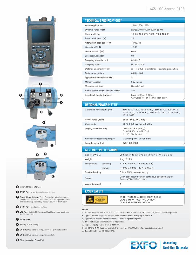
1 Infrared Printer Interface
2 OTDR Port | In-service singlemode testing.
3 Power Meter Detector Port | Compatible with almost every connector on the market. Manually and efficiently perform power and loss testing. Accurately measure power up to 26 dBm.
4 OTDR Port | Singlemode testing.
5 VFL Port | Built-in 650 nm visual fault location on a universal 2.5 mm connector.
6 AC Adapter
7 RJ-45 | TCP/IP testing.
8 USB B | Data transfer using ActiveSync or remote control.
9 USB A | Data transfer using memory stick.
10 Fiber Inspection Probe Port
AXS-100 Access OTDR
EXFO is certified ISO 9001 and attests to the quality of these products. This device complies with Part 15 of the FCC Rules. Operation is subject to the following two conditions: (1) this device may not cause harmful interference, and (2) this device must accept any interference received, including interference that may cause undesired operation. EXFO has made every effort to ensure that the information contained in this specification sheet is accurate. However, we accept no responsibility for any errors or omissions, and we reserve the right to modify design, characteristics and products at any time without obligation. Units of measurement in this document conform to SI standards and practices. In addition, all of EXFO’s manufactured products are compliant with the European Union’s WEEE directive. For more information, please visit www.EXFO.com/recycle. Contact EXFO for prices and availability or to obtain the phone number of your local EXFO distributor.
For the most recent version of this spec sheet, please go to the EXFO website at www.EXFO.com/specs.
In case of discrepancy, the Web version takes precedence over any printed literature.
EXFO Headquarters > Tel.: +1 418 683-0211 | Toll-free: +1 800 663-3936 (USA and Canada) | Fax: +1 418 683-2170 | [email protected] | www.EXFO.com
EXFO serves over 2000 customers in more than 100 countries. To find your local office contact details, please go to www.EXFO.com/contact.
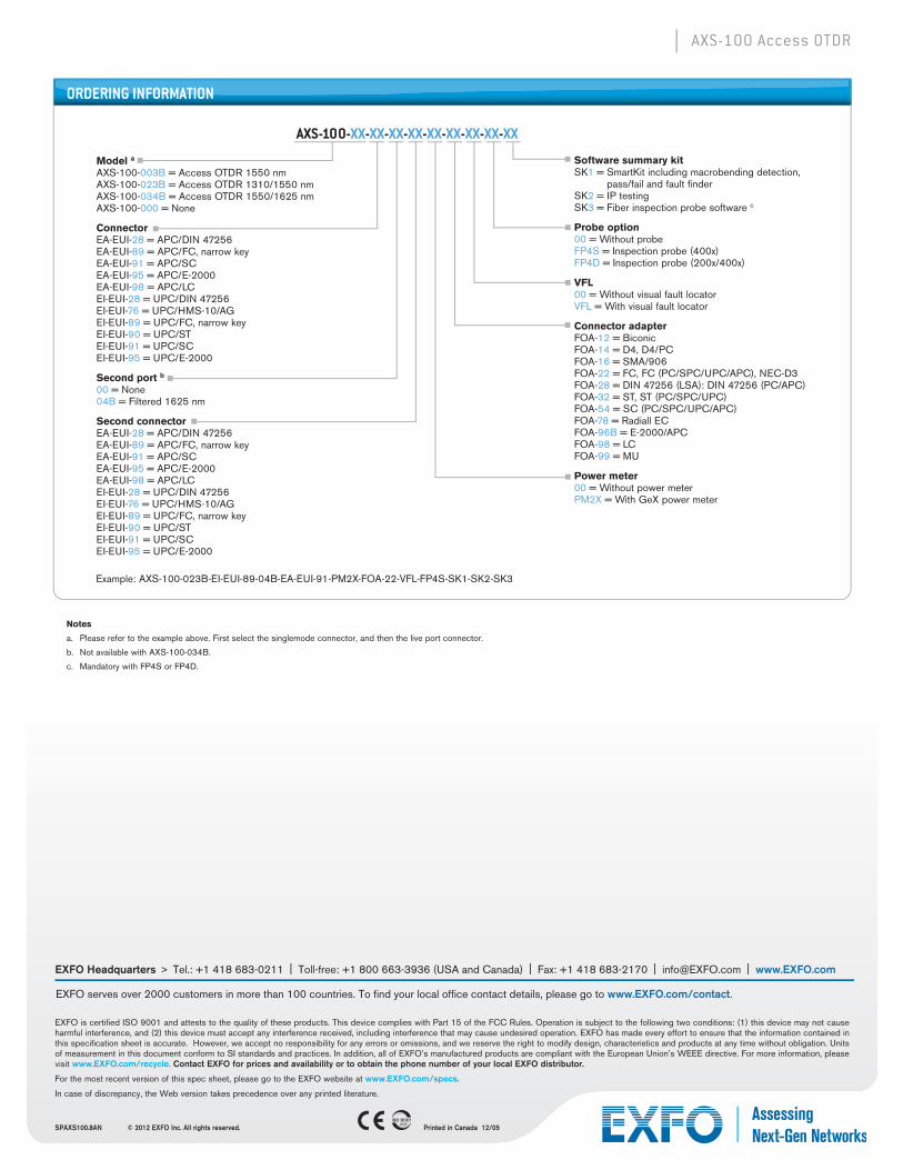
ORDERING INFORMATION
AXS-100-XX-XX-XX-XX-XX-XX-XX-XX-XX
Example: AXS-100-023B-EI-EUI-89-04B-EA-EUI-91-PM2X-FOA-22-VFL-FP4S-SK1-SK2-SK3
Notes
a. Please refer to the example above. First select the singlemode connector, and then the live port connector.
b. Not available with AXS-100-034B.
c. Mandatory with FP4S or FP4D.
Model a
AXS-100-003B = Access OTDR 1550 nmAXS-100-023B = Access OTDR 1310/1550 nmAXS-100-034B = Access OTDR 1550/1625 nmAXS-100-000 = None
ConnectorEA-EUI-28 = APC/DIN 47256EA-EUI-89 = APC/FC, narrow keyEA-EUI-91 = APC/SCEA-EUI-95 = APC/E-2000EA-EUI-98 = APC/LCEI-EUI-28 = UPC/DIN 47256EI-EUI-76 = UPC/HMS-10/AGEI-EUI-89 = UPC/FC, narrow keyEI-EUI-90 = UPC/STEI-EUI-91 = UPC/SCEI-EUI-95 = UPC/E-2000
Second port b
00 = None 04B = Filtered 1625 nm
Second connectorEA-EUI-28 = APC/DIN 47256EA-EUI-89 = APC/FC, narrow keyEA-EUI-91 = APC/SCEA-EUI-95 = APC/E-2000EA-EUI-98 = APC/LC EI-EUI-28 = UPC/DIN 47256EI-EUI-76 = UPC/HMS-10/AGEI-EUI-89 = UPC/FC, narrow keyEI-EUI-90 = UPC/STEI-EUI-91 = UPC/SCEI-EUI-95 = UPC/E-2000
Software summary kitSK1 = SmartKit including macrobending detection,
pass/fail and fault finderSK2 = IP testingSK3 = Fiber inspection probe software c
Probe option00 = Without probeFP4S = Inspection probe (400x) FP4D = Inspection probe (200x/400x)
VFL00 = Without visual fault locator VFL = With visual fault locator
Connector adapterFOA-12 = BiconicFOA-14 = D4, D4/PCFOA-16 = SMA/906FOA-22 = FC, FC (PC/SPC/UPC/APC), NEC-D3FOA-28 = DIN 47256 (LSA): DIN 47256 (PC/APC)FOA-32 = ST, ST (PC/SPC/UPC)FOA-54 = SC (PC/SPC/UPC/APC)FOA-78 = Radiall ECFOA-96B = E-2000/APCFOA-98 = LCFOA-99 = MU
Power meter00 = Without power meterPM2X = With GeX power meter
SPAXS100.8AN © 2012 EXFO Inc. All rights reserved. 2008
Printed in Canada 12/05