azipod® xo2100 and xo2300
TRANSCRIPT

Azipod® XO2100 and XO2300Product Introduction

2 chapter title | ABB brochure type
Preface
This Product Introduction provides system data and information for preliminary project planning of an Azipod® podded propulsion and steering system outfit. Furthermore, our project and sales departments are available to advise on more specific questions concerning our products and regarding the installation of the system components.
Our product is constantly reviewed and developed according to the technology progression and the needs of our customers. Therefore, we reserve the right to make changes to any data and information herein without notice.
All information provided by this publication is meant to be informative only. All project-specific issues shall be agreed separately and therefore any information given in this publication shall not be used as part of agreement or contract.
Helsinki, July 2012
ABB Oy, Marine and Cranes
Merenkulkijankatu 1/ P.O. Box 18500981 Helsinki FinlandTel. +358 10 22 11
http://www.abb.com/marine
Azipod is registered trademark of ABB Oy.© 2005 ABB Oy. All rights reserved
Doc. no. 3AFV6016618 rev. C / July 3rd, 2012
2 Preface | Azipod® XO2100 and XO2300 Product Introduction

ABB brochure type | chapter title 3
Index of items
Preface 2
Index of items 3
1 General 41.1 Azipod Propulsion and Steering 41.2 Improvements in the Azipod XO series 51.3 Type designation for the Azipod product 51.4 Electric propulsion and power plant 6
2 Technical features on the scope of supply 72.1 General 72.2 Azipod-specific delivered items 72.3 Main dimensions 92.4 Weights 112.5 Technical parameters: Propulsion Module 112.6 Technical parameters: steering and support systems 122.7 The steering gear 132.8 The cooling arrangement for the propeller motor 152.9 The shaft line bearing arrangement 16
3 Ambient reference conditions 183.1 Azipod 183.2 Azipod room requirements 18
4 Ship system interface 194.1 Ship automation interface 204.2 Ship auxiliary power supply interface 20
5 The remote control system 21
6 The Propulsion Condition Management System 226.1 General 226.2 Shaft bearing monitoring 236.3 Propulsion system monitoring 236.4 Nautical data interface 23
7 Ship design 247.1 Design flow 247.2 Hydrodynamics 247.3 Azipod location on the ship’s hull 257.4 Propeller 257.5 Forces on ship’s hull 25
8 Example of Azipod propulsion with the power plant 26
9 Information sheet for system quotation 27
Azipod® XO2100 and XO2300 Product Introduction | Index of items 3

4 chapter title | ABB brochure type
1 General
Azipod is an electric azimuthing propulsion system. The electric motor is inside a submerged pod. Propulsion module with speed controlled fixed pitch propeller can be rotated 360 degrees around its vertical axis. The system offers high efficiency with excellent maneuverability.
1.1 Azipod Propulsion and SteeringThe Azipod XO2100 and XO2300 are the successors to the classic “V21” and “V23” series Azipod products. Azipod propulsion is designed for the preferential use of the (directly driven) pulling propeller when driving in the ahead direction. The type XO2100 and XO2300 Azipod propulsion units are available generally for power ratings of between 13 - 18 MW and 18 – 23 MW respectively. The power rating is depending on the propeller design.
The full ship system consists of the required number of Azipod steering propulsors, plus the delivery of an PWM type marine Propulsion Power Drive per each Azipod. Additionally, propulsion supply transformers (if needed), a remote control system, and the power plant (generators, switchboards and transformers) are usually included in the scope of the delivery.
Figure 1-1 Basic arrangement of the Azipod XO
Steering Module
Propulsion Module
4 General | Azipod® XO2100 and XO2300 Product Introduction

ABB brochure type | chapter title 5
1.2 Improvements in the Azipod XO series
Subject Benefit
A. Easy access and work arrangements inside the Propulsion Module Safer work with extended possibilities for inspections and preventive
maintenance
B. Streamlined design of the Propulsion Module, and the propeller blades
and hub
Better hydrodynamic efficiency. Improved versatility for propeller instal-
lation procedures
C. Design of the propeller shaft bearings and seals to improve the life cycle
cost prognosis
Possibility to change shaft seals while in port. Thrust bearing assembly
with traditional white metal slide pad elements for the axial forces,
pads exchangeable while in port.
D. Fully electro-mechanical steering gear Contemporary solution with steering speed regulation versatility and
no need for pressure hydraulics
E. In-house designed remote controls for the Bridge and for the Engine
Control Room
Readily adaptable modularity for improved ergonomics, efficient ship
handling and project-specific Bridge design integration.
F. Advanced “Propulsion Condition Monitoring System”, as a variety of
options
Improved tool allowing continuous monitoring of the Azipod system
1.3 Type designation for the Azipod productIn the ship concept design stage, the following main designation is used. (A more specific type code will be allocated for the product during the advanced design stage).
C = “Compact” AzipodV = “Classic” AzipodX = Next Generation Azipod
O = Designed for operation in open water I = Designed for icebreaking or operation in ice conditionsC = “Contra-Rotation Propeller” use with traditional propulsionZ = Product with Kaplan propeller and nozzle for utility vessels
Diameter of the propulsion motor (mm.)
“S”, “M” or “L” = Length of the (synchronous) propulsion motor“A” = Asynchronous propulsion motor
Azipod® xxxx y
Example: Azipod® XO 2100 S
Azipod® XO2100 and XO2300 Product Introduction | General 5

6 chapter title | ABB brochure type
1.4 Electric propulsion and power plantIn order to drive the Azipod propulsion system, the ship needs an electric power plant (not specifically discussed in this document). Generator sets supply power to the 50 or 60 Hz installation of electric switchboards for distribution to all consumers onboard, including Azipod propulsion.
Generally, ABB aims to deliver the power plant as well as the Azipod system. Our mechanical interface to the engine maker is basically standard, although dependent on the delivery of engines or e.g. gas turbines from the contractors.
During the whole project, the basic tool for power plant design is the so-called single-line diagram. The actual onboard configuration can be efficiently discussed already in the early stages of work by using this clear visual representation.
Generators setsMain switchboards
Automation
Propulsion transformers
Control networkPower network
Frequency converters
Azipod®
Figure 1-2 Simplified single line diagram of the power plant with a propulsion system
6 General | Azipod® XO2100 and XO2300 Product Introduction

ABB brochure type | chapter title 7
2 Technical features on the scope of supply
2.1 GeneralThe Azipod Propulsion Module and the associated Steering Module are of fabricated steel construction. The Steering Module will be welded to the ship’s hull as a structural member. The submerged Propulsion Module incorporates a three-phase electric propeller motor in a dry environment, directly driving a fixed-pitch propeller.
The propeller is custom-designed by ABB to fit with the ship particulars confirmed by the shipyard.
The Propulsion Module is to be bolted to the azimuthing part of the Steering Module. Each Azipod delivery usually consists of the following fourteen items: two (2) modules and twelve (12) auxiliaries. They are built internally ready for separate deliveries, for shipyard installation, as follows:
2.2 Azipod-specific delivered items − Propulsion Module − Steering Module − Four (4) Steering Drives (SD-1...4) − One (1) Electric Steering Control Unit (ESCU) − One (1) Cooling Air Unit (CAU) − Two (2) adapting Air Ducts (AD-In), (AD-Out) − One (1) Slip Ring Unit (SRU) − One (1) Shaft line Support Unit (SSU) − One (1) Azipod Interface Unit (AIU) − One (1) Local Backup Unit (LBU)
A layout example of Azipod modules and units is shown in the figure 2-1.
The mounting, inter-unit connection, and external connection work of the above mentioned separate items is to be done by the shipyard, except for the ABB site installation work for the piping and cabling that interconnect the Propulsion Module and the Steering Module.
Azipod® XO2100 and XO2300 Product Introduction | Technical features on the scope of supply 7

8 chapter title | ABB brochure type
Azipod interface Unit (AIU)
Electric Steering Control Unit (ESCU)
Local Backup Unit (LBU)
Steering Drives (SD-1…4)
Slip Ring Units (SRU)
Air Duct (out) (AD-Out)
Air Duct (in) (AD-in)
Cooling Air Unit (CAU)
Steering Module
Propulsion Module
Shaft line Support Unit (SSU)
Figure 2-1 Layout example of Azipod XO series modules and auxiliaries
8 Technical features on the scope of supply | Azipod® XO2100 and XO2300 Product Introduction

ABB brochure type | chapter title 9
2.3 Main dimensions
Figure 2-2 Dimensional nominations for the Azipod XO series
Azipod® XO2100 and XO2300 Product Introduction | Technical features on the scope of supply 9
10 chapter title | ABB brochure type
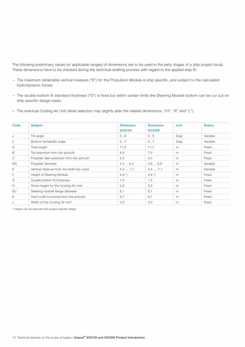
The following preliminary values (or applicable ranges) of dimensions are to be used in the early stages of a ship project study. These dimensions have to be checked during the technical drafting process with regard to the applied ship fit:
− The maximum obtainable vertical measure (“E”) for the Propulsion Module is ship specific, and subject to the calculated hydrodynamic forces.
− The double bottom fit standard thickness (“G”) is fixed but within certain limits the Steering Module bottom can be cut out on ship-specific design basis.
− The eventual Cooling Air Unit detail selection may slightly alter the related dimensions. (“H”, “K” and “L”).
Code Subject Dimension
XO2100
Dimension
XO2300
Unit Status
α Tilt angle 0...6 0...6 Degr Variable
β Bottom formability angle 0...7 0...7 Degr Variable
A Total length 11,5 11,7 m Fixed
B Tail extension from the azimuth 6,9 7,0 m Fixed
C Propeller disk extension from the azimuth 3,4 3,4 m Fixed
ØD Propeller diameter 4,4 ... 6,4 4,6 … 6,6 m Variable
E Vertical measure from the shaft line cross 4,3. ... 7,1 4,4. ... 7,1 m Variable
F Height of Steering Module 4,9 *) 4,9 *) m Fixed
G Double bottom fit thickness 1,5 1,5 m Fixed
H Room height for the Cooling Air Unit 3,0 3,0 m Fixed
ØJ Steering module flange diameter 6,1 6,1 m Fixed
K Hard outfit horizontal from the azimuth 6,7 6,7 m Fixed
L Width of the Cooling Air Unit 3,0 3,0 m Fixed
*) Height can be reduced with project specific design
10 Technical features on the scope of supply | Azipod® XO2100 and XO2300 Product Introduction

ABB brochure type | chapter title 11
2.4 WeightsPropulsion Module (excl. propeller):
XO2100 135 000 – 155 000 kgXO2300 157 000 – 180 000 kg
Propeller:XO2100 22 000 – 30 000 kgXO2300 25 000 – 36 500 kg
Steering Module 65 000 – 70 000 kgSlip Ring Unit (SRU) 4 000 kgSteering Drives (SD) 4 x 360 kgElectric Steering Control Unit (ESCU) 140 kgCooling Air Unit (CAU) 6 000 – 11 800 kgShaft Line Support Unit (SSU) 1 300 kgAir Ducts (AD-In), (AD-Out) Project specific, typically 2 x 400 kg Azipod Interface Unit (AIU) 200 kgLocal Back Up Unit (LBU) 20 kg
2.5 Technical parameters: Propulsion ModuleRated output power:
XO2100 13 000 – 18 000 kW XO2300 16 000 – 23 000 kW
Nominal propeller speed at rated output power:XO2100 122 – 170 rpm XO2300 112 – 155 rpm
Maximum nominal (ahead) torque To be definedMain motor supply voltage Approx. 3000 VMotor current To be definedInsulation / temperature rise class for stator and rotor F / FPropeller design 4 or 5 bladesPropeller type Medium skew and fixed pitchPropeller material Ni-Al BronzePropeller manufacturing and balancing ISO 484 class 1Propeller state when delivered Hub mounted on, blades looseShaft brake holding capacity Approx. 3.0 knots of water flowShaft locking capacity Approx. 10 knots of water flowNon-drive-end lube oil pump power 2 x 2.2 kWDrive-end lube oil pump power 2 x 1.1 kWDiaphragm drainage pumps capacity 2 – 3 x 1.0 m3/hDrainage pump air supply requirement 2 – 3 x 400 Nl/minDrainage pump air pressure requirements 7 bar Standstill heater resistance elements 4 x 800 WDisplacement 59 – 71 m3
Outside painting area 115 – 164 m2
Azipod® XO2100 and XO2300 Product Introduction | Technical features on the scope of supply 11
12 chapter title | ABB brochure type
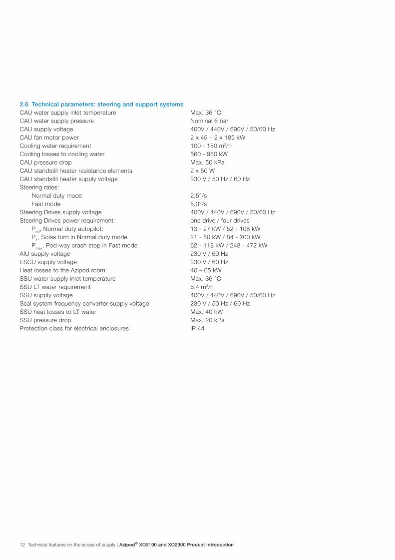
2.6 Technical parameters: steering and support systemsCAU water supply inlet temperature Max. 36 °C CAU water supply pressure Nominal 6 barCAU supply voltage 400V / 440V / 690V / 50/60 HzCAU fan motor power 2 x 45 – 2 x 185 kWCooling water requirement 100 - 180 m3/hCooling losses to cooling water 560 - 980 kW CAU pressure drop Max. 50 kPaCAU standstill heater resistance elements 2 x 50 WCAU standstill heater supply voltage 230 V / 50 Hz / 60 HzSteering rates:
Normal duty mode 2,5°/sFast mode 5,0°/s
Steering Drives supply voltage 400V / 440V / 690V / 50/60 HzSteering Drives power requirement: one drive / four drives
Pref, Normal duty autopilot: 13 - 27 kW / 52 - 108 kWP1, Solas turn in Normal duty mode 21 - 50 kW / 84 - 200 kWPmax, Pod-way crash stop in Fast mode 62 - 118 kW / 248 - 472 kW
AIU supply voltage 230 V / 60 HzESCU supply voltage 230 V / 60 HzHeat losses to the Azipod room 40 – 65 kWSSU water supply inlet temperature Max. 36 °CSSU LT water requirement 5.4 m3/hSSU supply voltage 400V / 440V / 690V / 50/60 HzSeal system frequency converter supply voltage 230 V / 50 Hz / 60 HzSSU heat losses to LT water Max. 40 kWSSU pressure drop Max. 20 kPaProtection class for electrical enclosures IP 44
12 Technical features on the scope of supply | Azipod® XO2100 and XO2300 Product Introduction

ABB brochure type | chapter title 13
2.7 The steering gearThe fully electro-mechanic steering gear allows unlimited steering of the Propulsion Module. The main components of the system are: Electric Steering Control Unit (ESCU), inverter Steering Drives (SD1...4) steering motors, reduction gears, pinions, gear rim, slewing bearing and slewing seals.
Figure 2-3 Split view of the top delivery showing the steering gear mechanics
The steering motors are of the asynchronous induction type and each is driven by its own (inverter type) steering frequency converter. The typical Steering Module configuration includes four motors, depending on the ultimate torque requirements.
A self-arming torque overload clutch is provided on the shaft between each steering motor and reduction gear. The planetary reduction gear transfers the torque from each electric steering motor to the respective pinion. Each steering motor is fitted with a fail-to-safe (normally spring shut) steering brake to prevent unwanted motion of the pod in case of a technical eventuality or when all the steering drives are off.
Each pinion is made of hardened steel and the gear teeth are machined directly to the shaft of the pinion. The pinion bearing arrangement consists of two roller bearings. The gear rim transfers the torque from the pinions to the Propulsion Module and is made of hardened steel and bolted to the slewing bearing. The bearings and the whole gear assembly are lubricated with oil by bath and splash lubrication. The three-row roller type slewing bearing supports the weight of the Propulsion Module and enables it to steer around its vertical axis.
Each Steering Drive cabinet consists of two separate sections, one for the converter and the other for the braking resistors. Both of these main sections are air cooled by their own fans.
Azipod® XO2100 and XO2300 Product Introduction | Technical features on the scope of supply 13
14 chapter title | ABB brochure type
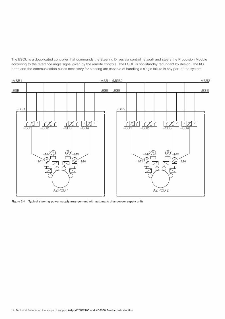
The ESCU is a doublicated controller that commands the Steering Drives via control network and steers the Propulsion Module according to the reference angle signal given by the remote controls. The ESCU is hot-standby redundant by design. The I/O ports and the communication buses necessary for steering are capable of handling a single failure in any part of the system.
;MSB1 ;MSB1 ;MSB2 ;MSB2
;ESB
=SG1
=SD1 =SD1=SD2 =SD2
=M2 =M2M MM M
M MM M
=M3 =M3
=M1 =M1=M4 =M4
AZIPOD 1 AZIPOD 2
=SD3 =SD3=SD4 =SD4
=SG2
;ESB ;ESB ;ESB
Figure 2-4 Typical steering power supply arrangement with automatic changeover supply units
14 Technical features on the scope of supply | Azipod® XO2100 and XO2300 Product Introduction

ABB brochure type | chapter title 15
2.8 The cooling arrangement for the propeller motorThe Cooling Air Unit is provided with radial type fans and double tube type fresh water heat exchangers for connection into the ship’s LT water system.The Cooling Air Unit is provided with the following components and accessories:
− Leakage detector per each cooler − Air cooling ducts with inserted air filter elements − Flexible bellows with counter flanges for the ship’s LT technical fresh water supply
Figure 2-5 The air cooling arrangement of the propulsion motor
Azipod® XO2100 and XO2300 Product Introduction | Technical features on the scope of supply 15
16 chapter title | ABB brochure type
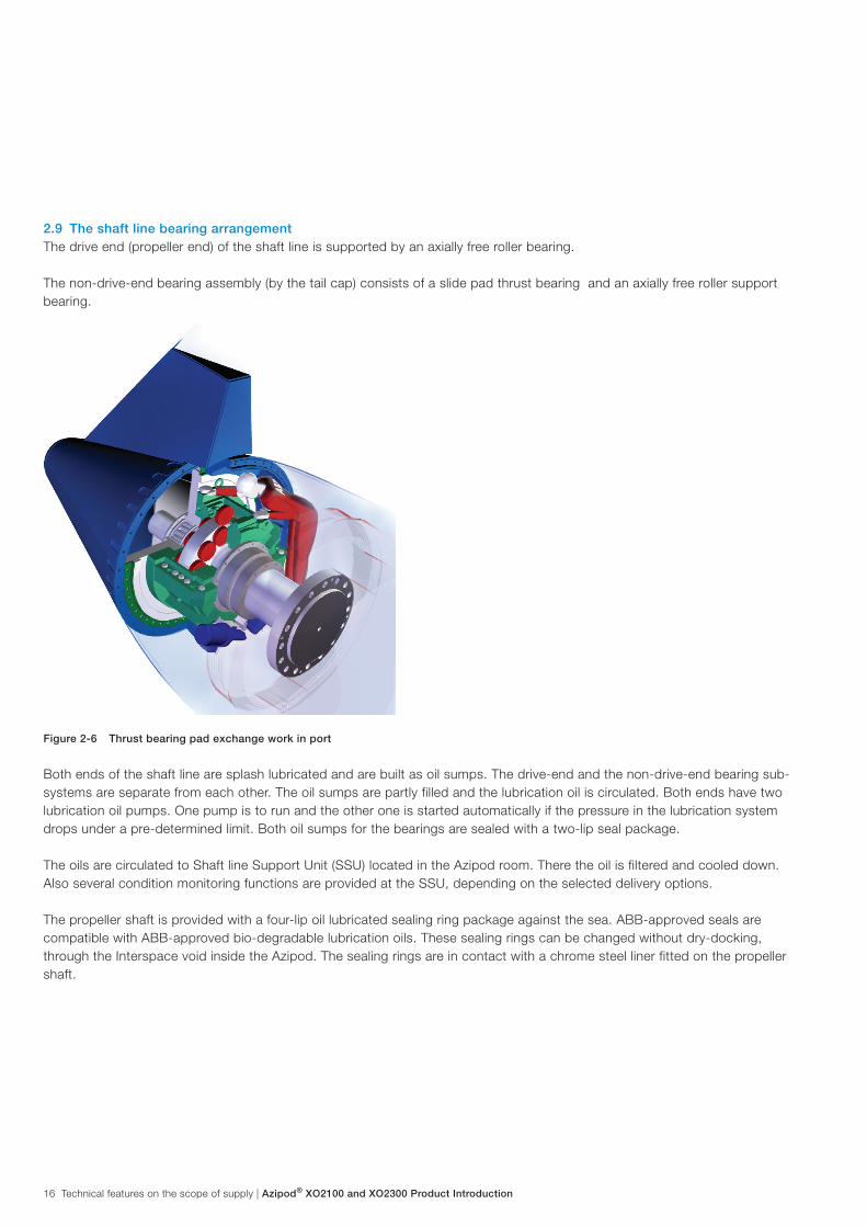
2.9 The shaft line bearing arrangementThe drive end (propeller end) of the shaft line is supported by an axially free roller bearing.
The non-drive-end bearing assembly (by the tail cap) consists of a slide pad thrust bearing and an axially free roller support bearing.
Figure 2-6 Thrust bearing pad exchange work in port
Both ends of the shaft line are splash lubricated and are built as oil sumps. The drive-end and the non-drive-end bearing sub-systems are separate from each other. The oil sumps are partly filled and the lubrication oil is circulated. Both ends have two lubrication oil pumps. One pump is to run and the other one is started automatically if the pressure in the lubrication system drops under a pre-determined limit. Both oil sumps for the bearings are sealed with a two-lip seal package.
The oils are circulated to Shaft line Support Unit (SSU) located in the Azipod room. There the oil is filtered and cooled down. Also several condition monitoring functions are provided at the SSU, depending on the selected delivery options.
The propeller shaft is provided with a four-lip oil lubricated sealing ring package against the sea. ABB-approved seals are compatible with ABB-approved bio-degradable lubrication oils. These sealing rings can be changed without dry-docking, through the Interspace void inside the Azipod. The sealing rings are in contact with a chrome steel liner fitted on the propeller shaft.
16 Technical features on the scope of supply | Azipod® XO2100 and XO2300 Product Introduction

ABB brochure type | chapter title 17
Figure 2-7 Shaft water seal exchange (work in port) through the Interspace
A hydraulic disc brake is provided for holding the propeller shaft during maintenance. The brake is connected manually and activated by a hydraulic hand pump. The holding capacity depends on the propeller design. Mechanical locking is provided for an emergency situation. Locking action is achieved with a mechanical locking piece. The maximum allowed water speed of the ship while locking the shaft depends on the design of the propeller.
A gear rim operates the absolute positional encoder transmitters on the shaft. One encoder operates and the other is provided for backup. Four (4) shaft earthing assemblies are provided on the shaft, two in the drive end and two in the non-drive end.
Figure 2-8 The shaft line lube oil arrangement
Azipod® XO2100 and XO2300 Product Introduction | Technical features on the scope of supply 17

18 chapter title | ABB brochure type
3.1 AzipodRated sea water temperature -2…+ 32°CMaximum resultant mounting angle (longitudinal and lateral) 4°The maximum allowed combined resultant of the mounting angleand of the propulsion module tilt angle α *) is 6°
Mounting angle
Mounting angle
Figure 3 1 Mounting angles (longitudinal and lateral)
Azipod is rated as a Permit Required Confined Space for personnel entry. Asphyxiating fire-fighting media may not be released into the Azipod Propulsion Module, if physical personnel entry is possible.
3.2 Azipod room requirementsThe Azipod room needs to be rated as a Machinery area with sufficient air conditioning. The humidity inside the room needs to remain at a level were no condensation occurs on any parts. The rated normal temperature is between +10 …+ 45°C,
*) see section 2.3 Main dimensions
3 Ambient reference conditions
18 Ambient reference conditions | Azipod® XO2100 and XO2300 Product Introduction

ABB brochure type | chapter title 19
4 Ship system interface
(Azipod scope of delivery)
(Azipod room heat load)Ship‘s engine room
air conditioningcapacity
Ship‘s machinery
and automation
systemShip‘s
Passive supply
breakers
Ship‘s MCC (Active supply
breakers)
Ship‘s LT fresh
cooling water
system
Ship‘s oily water tank
Ship‘s pressure
air systems
Control
Electric Steering Gear
4 x consumer (from Main Switchboard)
4 x consumer (from Emerg. Switchboard)
Group alarms
Control request and info
MCC status info
4 x consumer (rotating)
1 x consumer (heater)
3 x consumer (rotating)
2 x consumer (rotating)
2 x consumer (heater)
2 x Water inlet
2 x Water return
1 x Water inlet
1 x Water return
1 x consumer (rotating)
2 x (redundant) air lines
1 x discharge
AIU Box
Cooling Air Unit(CAU)
Shaft lineSupport Unit(SSU)
Slip Ring Unit (SRU)
Pumps,valves
sensors
(Ship systems‘ scope)
Figure 4-1 Typical interface with the ship’s systems
Azipod® XO2100 and XO2300 Product Introduction | Ship system interface 19

20 chapter title | ABB brochure type
4.1 Ship automation interfaceThe auxiliary functions of the Azipod delivery are controlled by the ship’s machinery and automation system. Therefore, an interface has to be created. The ship’s machinery and automation system supplier and the shipyard, as well as ABB, need to define together the related I/O specification and also the appropriate visual screen display views that are provided from the ship’s machinery and automation system. The Azipod interface to the ship automation is based on Modbus RTU protocol, where ABB works as the master.
Azipod Interface Unit (AIU) sends control request to the ship’s machinery and automation system. The ship’s machinery and automation system is in charge of the following functions:1. Control of propulsion auxiliaries2. Control of cooling air subsystem3. Control of shaft line oil circulation4. Group monitoring and alarms imported from independent ABB sub-systems, to a detail and to an extent that need to be
defined during the project design stage
4.2 Ship auxiliary power supply interfaceThe shipyard delivers the motor starter functionalities for the electric motors of the Azipod auxiliaries. Potential free (closing relay) binary contacts are required by ABB from the shipyard’s motor control center functionality (MCC) as output status information in hard wiring.
20 Ship system interface | Azipod® XO2100 and XO2300 Product Introduction

ABB brochure type | chapter title 21
The Azipod scope of supply is enhanced with the ABB “IMI” (= Intelligent Maneuvering Interface) remote control and operator guidance indication system. This provides an up-to-date control outfit for the Bridge and for the Engine Control Room and can be elegantly installed into the various externally supplied Bridge console deliveries seen on the commercial shipbuilding market today. The control items are intended for consoles that are located indoors.
The remote control system provides on-line operator guidance and feedback for optimal Azipod use. The purpose of this functionality is to promote economical and smooth ship operation.
This bus-based system is designed redundant and is engineered in-house at ABB Marine. A hard-wired back-up sub-system is included. Many different modular control configurations can be provided, also including optional command and control post change functions for an external bow thruster system.
The usual industrial standard interfaces are provided for external Autopilot, external Joystick / DP and external Voyage Data Recorder.
5 The remote control system
Figure 5-1 Typical remote control outfit
Azipod® XO2100 and XO2300 Product Introduction | The remote control system 21

22 chapter title | ABB brochure type
6 The Propulsion Condition Management System
6.1 GeneralThe Propulsion Condition Management System (PCMS) is the technical solution for condition monitoring of the critical components of the Azipod and propulsion system. The PCMS acquires and stores data continuously from several sources and provides functions for: − Condition monitoring
− Wear and lifetime analysis − Remote diagnostics
− Troubleshooting − Scheduled audits and reporting
The PCMS functions implemented onboard are tailored specifically to the agreed extents and requirements of the ship project.
Figure 6-1 Layout of the PCMS
22 The Propulsion Condition Management System | Azipod® XO2100 and XO2300 Product Introduction
Azipod room
Frequency converter room
Controller
Control network
TCP/IP
DDCS
PCSoperator
panel
PCMSserver
RS422
BlueTooth
ECRTCP/IP
TCP/IP (optic fibre)
TCP/IP
Azipod Diagnostic Module (ADM)
Data collection fromVibration measurement moduleFrequency converter AMC boardAIU controller (through PCS op. panel)PCU controller (through PCS op. panel)
Writes data to the database on PCMS server
Vibration Measurement Module (VMM)
Measures vibration from the shaft bearings
Central Diagnostic Module (CDM)
Database for PCMS data
User interfaceLocal operator userRemote service userPCMS administrator (local or remote)
Connections to other systems of the vesselVPN connection through satelliteNautical systems (read only)Propulsion control system (read only)
Other ADMs
DriveMonitor
Nautical systems
VPN
Network switch
Network switchSerial gateway
AMC board(in Freq.
Converter)
Azipod room
Frequency converter room
Controllerin the AIU
(pod aux. info)
BlueTooth
TCP/IP (optic fibre)
Access point in the SRU
Access point in the SRU
Controllerin the AIU
(pod aux. info)
PCU
Controller
TCP/IP
DDCSAMC board
(in Freq.Converter)
PCU
Network switch DriveMonitor
ABB brochure type | chapter title 23
6.2 Shaft bearing monitoringCondition monitoring of the shaft bearings is based on recorded vibration, temperature and lubrication oil properties. The analysis functions provide information for the operator to monitor the bearing condition. All analyses are performed for both drive end and non-drive end bearings.
A. Vibration: Bearing vibrations are measured by acceleration transducers at wide bandwidth. Several analysis functions are performed on the results in order to detect wearing, lubrication problems or possible other operational defects.
B. Temperatures: Bearing and lubrication oil temperatures are measured by several sensors. The resulting trends are stored in the PCMS.
C. Lubrication oil properties: the following attributes are monitored by means of various sensors installed in the Shaft Line Support Unit (SSU):
− Humidity − Contamination − Metal particles
6.3 Propulsion system monitoringA. The alarms and events from the propulsion system are recorded. This enables following and tracking faults or alarms
also after they have been cleared from the system. The PCMS itself does not generate alarms for other systems in the ship. The events are read from:
− The Azipod Interface Unit (AIU) − The Propulsion Control Unit (PCU) − The Propulsion Power Drive
B. Trends are also recorded from the main quantities that define the operation point of the propulsion system. These include data from the Azipod, frequency converter, propulsion motor and propulsion control system.
6.4 Nautical data interfaceData from external nautical systems is acquired in conjunction with the bearing vibration measurements in order to account for environmental factors in the vibration levels. PCMS does not introduce new measurements, but the data is read from the ship’s systems.
Azipod® XO2100 and XO2300 Product Introduction | The Propulsion Condition Management System 23
24 chapter title | ABB brochure type
7 Ship design
The following paragraphs describe the usual shipyard design process with Azipod:
7.1 Design flowA. After defining the basic ship layout, the Azipod Propulsion Module is chosen based on the thrust or propeller torque
requirements (generally ruled by the ship’s speed vs. resistance curve).
B. The Steering Module is selected in function of the steering torque, usually defined by the propeller power, strut height, and the speed of the ship. The ship’s power plant dimensioning is checked to match the performance of the two modules.
C. The auxiliaries are chosen to fit the Propulsion and Steering Modules. As above, any special redundancy requirements must be agreed on within the limits of specified options.
D. Azipod room design work (with the appropriate fire area definition) is carried out.
E. System interfaces are detailed with the allocation of ship automation points.
F. The ship control layout is configured.
7.2 HydrodynamicsThe shipbuilder begins the hydrodynamic design of the ship with the following steps:
A. Sketching the after lines of the podded ship, locating the Azipod unit(s)
B. Estimating the propeller diameter and tip clearance (head box configuration, if required)
C. Defining the speed vs. thrust curve for the ship on given draught conditions
D. Selecting the required power and rpm value for the propeller(s)
E. Contacting ABB with an inquiry
24 Ship design | Azipod® XO2100 and XO2300 Product Introduction

ABB brochure type | chapter title 25
7.3 Azipod location on the ship’s hullIt is important to place the Azipod at the correct location on the ship’s hull. Typically any part should not come out by the side or by the transom. According to experience in the twin Azipod solution it is recommended that the pods are located as far astern and as close to the ship’s sides as possible. Azipod Propulsion Modules have to be located so far from each other that sufficient clearance between is maintained at all steering angles (recommended minimum 300…500 mm, depending on the case). For more accurate design, the hull shape of the ship and water flow must be considered.
7.4 PropellerAzipod propellers are always fixed-pitch propellers (FPP) because of the control of propeller speed and torque by a frequency converter. The typical Azipod has a pulling-type propeller as a monoblock or with built-on blades. The optimized propeller is tailored for the ship. ABB is in charge of the propeller design, and it is done in close co-operation with the designers of the shipbuilder.
7.5 Forces on ship’s hullForces from the Propulsion Module are transferred to the ship’s hull steel structure trough the steering module. The Steering Module is to be welded to the ship’s hull as a structural member. ABB delivers the calculated support loads and the recommended installation instructions for the mounting of the steering module.
Azipod® XO2100 and XO2300 Product Introduction | Ship design 25

26 chapter title | ABB brochure type
8 Example of Azipod propulsion with the power plant
In this typical example four main generators are connected to the main switchboard, and the low voltage switchboard is supplied by ship service transformers. The main switchboard can be divided into two separate networks by means of the tie breakers to increase the redundancy of the power plant.
Figure 7-1 Typical single line diagram of the onboard power plant
26 Example of Azipod propulsion with the power plant | Azipod® XO2100 and XO2300 Product Introduction
11000 V – 60HzIk=25 kAIn=1600 A
BT23 000 kW
G3~
Feed
er fo
rA/C
com
pres
sor m
otor
Feed
er fo
rA/C
com
pres
sor m
otor
Feed
er fo
rA/C
com
pres
sor m
otor
Feed
er fo
rA/C
com
pres
sor m
otor
MSB-MV 111000 V – 60Hz
MSB-MV 2
DG213 300 kVA cosphi 0,9514 rpm
BT33 000 kW
G3~
G3~
BT13 000 kW
DG111 700 kVAcosphi 0,9514 rpm
Shore connection 516 A @ 45 C
DG313 300 kVAcosphi 0,9514 rpm
DG411 700 kVAcosphi 0,9514 rpmG
3~
M3~
M3~
Eng. room Tr12 500 kVA
Eng. room Tr22 500 kVA
Em’cy Tr11 875 kVA
Prop Tr8 050 kVA
11 000 // 2 x 1 680 V
Prop Tr8 050 kVA
11 000 // 2 x 1 680 V
M3~
Eng. room Tr32 500 kVA
Eng. room Tr42 500 kVA
ET400 kVA
fed from LV
ET400 kVA
fed from LV
M3~
Azipod XO210014 MW
approx. 137 rpm
ACS 6000 SD
ET400 kVA
fed from LV
ET400 kVA
fed from LV
M3~
Azipod XO210014 MW
approx. 137 rpm
ACS 6000 SD

ABB brochure type | chapter title 27
9 Information sheet for system quotation
Our intention is to work together with our customers to optimize ship design related to the total building concept. All additional information related to the ship’s operating profile and other special requirements will also be helpful.
Shipyard:
Owner:
Type of ship:
Main dimensions of the ship: Lpp= , B=
T= , GT/DWT =
Block coefficient or displacement:
Estimate of the resistance (naked hull):
Speed of the ship:
Classification society:
Special notations (Ice class, DP, etc.):
Number of Propulsion Modules per ship:
Estimated Propulsion Module power:
Estimated propeller diameter and rpm:
Bollard pull requirement:
Main generator sets:
(type, rpm, number and power of units)
Main switchboard voltage and frequency:
Auxiliary switchboard voltage:
Bow thruster power:
Ship’s electrical auxiliary and hotel load:
Number of ships to be built:
Delivery time for the equipment:
Delivery time of the ship:
Attachments: (GA drawing, etc...)
Azipod® XO2100 and XO2300 Product Introduction | Information sheet for system quotation 27

Contact us
ABB Oy, Marine and CranesMerenkulkijankatu 1 / P.O. Box 18500981 Helsinki, FinlandTel. +358 10 22 11
www.abb.com/marine