ballistic puncture self-healing polymeric materials …...1 ballistic puncture self-healing...
TRANSCRIPT
July 2017
NASA/TM–2017-219642
Ballistic Puncture Self-healing Polymeric Materials
���������� ������������������������������������������������������������������ ���������������!��������� ������"��#�$��������%�"��������!����������&�����'�������������
�
�
�
https://ntrs.nasa.gov/search.jsp?R=20170007198 2020-03-04T12:19:35+00:00Z
NASA STI Program . . . in Profile
Since its founding, NASA has been dedicated to the advancement of aeronautics and space science. The NASA scientific and technical information (STI) program plays a key part in helping NASA maintain this important role.
The NASA STI program operates under the auspices of the Agency Chief Information Officer. It collects, organizes, provides for archiving, and disseminates NASA’s STI. The NASA STI program provides access to the NTRS Registered and its public interface, the NASA Technical Reports Server, thus providing one of the largest collections of aeronautical and space science STI in the world. Results are published in both non-NASA channels and by NASA in the NASA STI Report Series, which includes the following report types:
• TECHNICAL PUBLICATION. Reports of completed research or a major significant phase of research that present the results of NASA Programs and include extensive data or theoretical analysis. Includes compilations of significant scientific and technical data and information deemed to be of continuing reference value. NASA counter-part of peer-reviewed formal professional papers but has less stringent limitations on manuscript length and extent of graphic presentations.
• TECHNICAL MEMORANDUM. Scientific and technical findings that are preliminary or of specialized interest, e.g., quick release reports, working papers, and bibliographies that contain minimal annotation. Does not contain extensive analysis.
• CONTRACTOR REPORT. Scientific and technical findings by NASA-sponsored contractors and grantees.
• CONFERENCE PUBLICATION. Collected papers from scientific and technical conferences, symposia, seminars, or other meetings sponsored or co-sponsored by NASA.
• SPECIAL PUBLICATION. Scientific, technical, or historical information from NASA programs, projects, and missions, often concerned with subjects having substantial public interest.
• TECHNICAL TRANSLATION. English-language translations of foreign scientific and technical material pertinent to NASA’s mission.
Specialized services also include organizing and publishing research results, distributing specialized research announcements and feeds, providing information desk and personal search support, and enabling data exchange services.
For more information about the NASA STI program, see the following:
• Access the NASA STI program home page at http://www.sti.nasa.gov
• E-mail your question to [email protected]
• Phone the NASA STI Information Desk at 757-864-9658
• Write to: NASA STI Information Desk Mail Stop 148 NASA Langley Research Center Hampton, VA 23681-2199

National Aeronautics and Space Administration
Langley Research Center Hampton, Virginia 23681-2199
July 2017
NASA/TM–2017-219642
Ballistic Puncture Self-healing Polymeric Materials
���������� ����������������������������������������������������������������� ���������������!��������� ������"��#�$��������%�"��������!����������&�����'�����������
�
Available from:
NASA STI Program / Mail Stop 148 NASA Langley Research Center
Hampton, VA 23681-2199 Fax: 757-864-6500
Acknowledgments
We thank the Lafayette gun club (Yorktown, VA) for allowing the ballistic testing to be conducted on their facilities. We acknowledge the following colleagues for their contributions: Ms. Crystal Chamberlain for thermal analysis of polymers, Ms. Janice Smith for mechanical testing of polymers, Mr. Charles Townsley for mechanical testing of specimens, Mr. Sean Britton for compression molding of polymer panels, Mr. Brian Grimsley and Mr. Zackary Schiferal for rheology measurements, Mr. Dennis Working for injection molding of dogbone specimens, Mr. Paul Bagby for high speed video recording of ballistic testing, and Mr. Jeff Seebo and Mr. Sidney Allison for Grey-field Polariscope Measurements and Dr.(s) Kris Wise, Godfrey Sauti, and Kevin Hadley for valuable discussions and assistance. We also thank Dupont and Entec resins for providing free samples of their respective products.
The use of trademarks or names of manufacturers in this report is for accurate reporting and does not constitute an official endorsement, either expressed or implied, of such products or manufacturers by the National Aeronautics and Space Administration.
1
Ballistic Puncture Self-healing Polymeric Materials
Abstract
Space exploration launch costs on the order of $10,000 per pound provide an incentive to seek ways to reduce structural mass while maintaining structural function to assure safety and reliability. Damage-tolerant structural systems provide a route to avoiding weight penalty while enhancing vehicle safety and reliability. Self-healing polymers capable of spontaneous puncture repair show promise to mitigate potentially catastrophic damage from events such as micrometeoroid penetration. Effective self-repair requires these materials to quickly heal following projectile penetration while retaining some structural function during the healing processes. Although there are materials known to possess this capability, they are typically not considered for structural applications. Current efforts use inexpensive experimental methods to inflict damage, after which analytical procedures are identified to verify that function is restored. Two candidate self-healing polymer materials for structural engineering systems are used to test these experimental methods.
Introduction
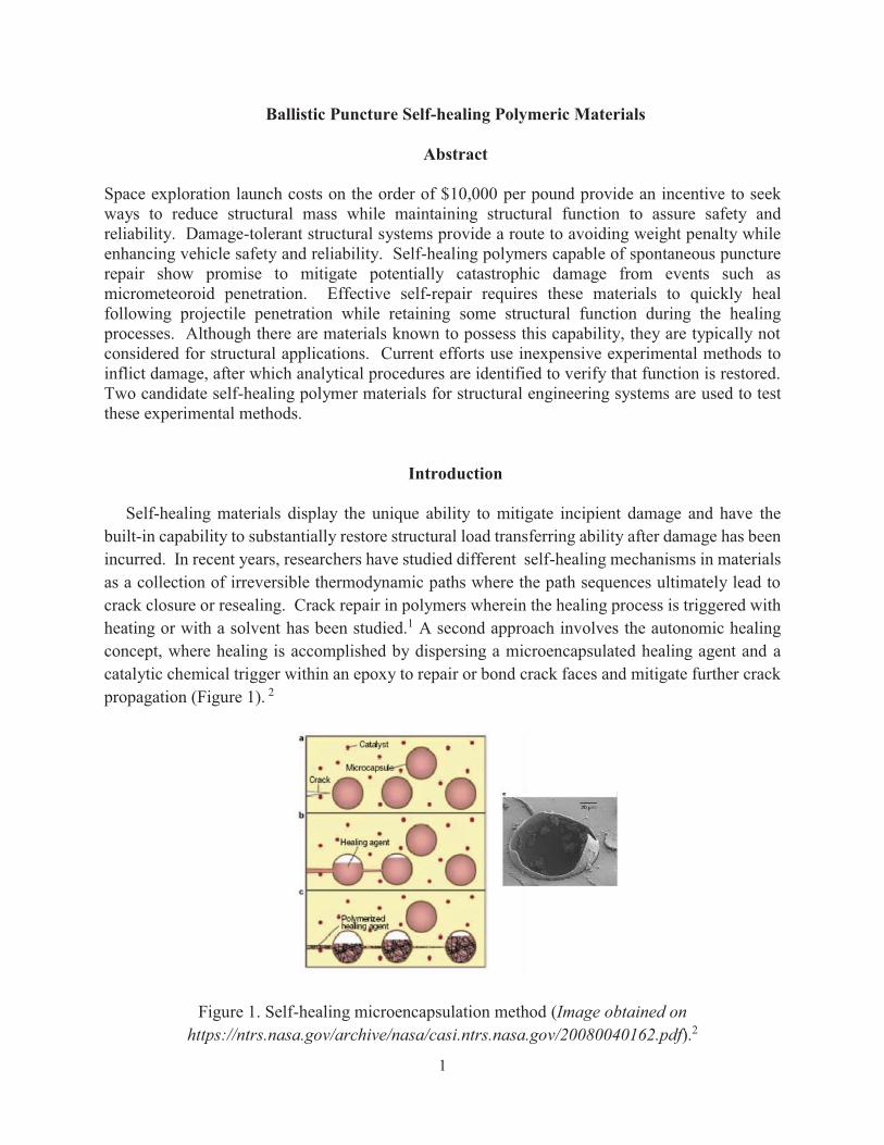
Self-healing materials display the unique ability to mitigate incipient damage and have the built-in capability to substantially restore structural load transferring ability after damage has been incurred. In recent years, researchers have studied different self-healing mechanisms in materials as a collection of irreversible thermodynamic paths where the path sequences ultimately lead to crack closure or resealing. Crack repair in polymers wherein the healing process is triggered with heating or with a solvent has been studied.1 A second approach involves the autonomic healing concept, where healing is accomplished by dispersing a microencapsulated healing agent and a catalytic chemical trigger within an epoxy to repair or bond crack faces and mitigate further crack propagation (Figure 1). 2
Figure 1. Self-healing microencapsulation method (Image obtained on https://ntrs.nasa.gov/archive/nasa/casi.ntrs.nasa.gov/20080040162.pdf).2
2
A related approach, the microvascular concept, utilizes brittle hollow glass tubes or fibers, instead of microcapsules, filled with epoxy hardener and uncured resin in alternate layers, with fluorescent dye.3-5 An approaching crack ruptures fluid filled glass tube/fiber and releases the healing agent into the crack plane through capillary action. Additionally, vascular self-healing materials may also sequester the healing agent in capillary type hollow channels which can be interconnected to form two dimensional (2D) and three dimensional (3D) networks.6 A third approach utilizes a polymer that can reversibly re-establish its broken bonds at the molecular level by either thermal activation (e.g., based on Diels-Alder rebonding), or ultraviolet light. 7-11 A fourth approach, structurally dynamic polymers, are materials that produce macroscopic responses from a change in the material’s molecular architecture without heat or pressure.12-17 These self-healing approaches have the following disadvantages in common: (1) slow rates of healing, (2) use of foreign inserts in the polymer matrix that may have detrimental effects on composite performance, (3) samples have to be held in intimate contact or under load and/or fused together under high temperature, and/or (4) may not be considered a structural load bearing material.
In contrast to the above mechanisms, inherent self-healing capability is possible for ionomers. These materials contain ionic groups at low concentrations (< 15 mol%) along the polymer backbone.18,19 In the presence of oppositely charged ions, these ionic groups form aggregates that can be activated by external stimuli such as temperature or ultraviolet irradiation. For example, poly(ethylene-co-methacrylic acid) (EMMA), also known as Surlyn®, undergoes puncture reversal (self-healing) following high velocity ballistic penetration. The heat generated from the damage event triggers self-healing in this material. Ballistic testing of EMAA copolymers with ionic segments was conducted by Kalista and Ward and further investigated by Varley and van der Zwaag. 20-23 Although EMMA polymers possess excellent puncture healing properties, its low tensile modulus (308 MPa) limits its use as an engineering polymer in structural aerospace applications. In this report, the effects of damage inflicted by high speed projectile penetration as the genesis of a healing process, and the post-damage effects on the mechanical properties of puncture healing polymers were examined. Ballistic tests performed at a firing range were used to simulate micrometeoroid damage. Differential Scanning Calorimetry (DSC), Dynamic Mechanical Analysis (DMA), Instron Microtester, and Rheology were used to assess material properties. High Speed Video and High Speed Thermography were utilized to capture and elucidate the healing mechanism. A Grey-field Polariscope, the operation of which is covered in the Appendix, was used to measure changes in morphology in polymers after projectile penetration. Tensile strengths of panels after ballistic penetration were compared with measurements on pristine panels to determine changes in load-bearing properties.
3
Methods
Surlyn® 8940 (Dupont), Affinity EG8200G (Entec resins), and Lexan® (GE) samples were provided by their respective manufacturers/distributors. Poly(butylene terephthalate) (PBT), poly(butylene terepthalate)-co-poly(alkylene glycol terepthalate) (PBT-co-PAGT), and poly(butadiene)-graft-poly(methyl acrylate-co-acrylonitrile) (PB-g-PMA-co-A) were purchased from Sigma-Aldrich Company and used as received. The thermal properties of the polymers were characterized by Differential Scanning Calorimetry (DSC) and Dynamic Mechanical Analysis (DMA). DSC was conducted using a NETZSCH model 204-F1 Phoenix differential scanning calorimeter. Thermal scans were conducted at a rate of 20oC/min in nitrogen and air. DMA was also utilized to obtain molecular relaxations in the polymers studied. All experimental data were collected using a TA Instruments DMA Q800 dynamic mechanical analyzer equipped with a single cantilever clamp. A Grey-field Polariscope (GFP) 1400C was utilized to measure residual stresses in panels before and after ballistic testing. GFP is sensitive to residual stresses and crystallinity in materials. Mechanical properties were also assessed by Sintech 2W instron according to ASTM D638 at crosshead speeds of 5.08 mm/min.24 The mechanical properties of polymers in these studies may be less than reported values due to the injection molding process used to generate dogbone specimens for mechanical testing. Rheometry was utilized to obtain viscosity and melt flow properties of the polymers at various temperatures. All of the rheology results presented in this study were collected using a cyclic strain of 2%. A dynamic temperature scan in nitrogen was conducted from 25ºC to 285ºC at 5ºC/min. The Dynamic Mechanical Analysis Time Temperature Superposition (TTS) technique was utilized to obtain viscoelastic properties of polymers. The results presented in this paper were for two distinct types of mechanical tests conducted on the samples of Surlyn® and PB-g-PMA-co-A. For temperature sweeps to measure the glass transition temperature (Tg), the samples were tested at a constant frequency of 1 Hz while the temperature was increased from cryo temperatures to at least 175oC at rates of 1.0oC/min and 3.0oC/min. For the frequency domain analysis, the samples were tested under isothermal conditions from 1.0 – 100 Hz at five frequencies per decade, evenly spaced in log frequency space. After the testing at a particular temperature was completed, the temperature was then raised 10oC, held isothermally for 5 min, and the frequency scanning at the new test temperature was conducted. The procedure was repeated until the final test temperature was reached. The results were manually shifted using time-temperature superposition (TTSP) to generate a master curve with respect to a reference curve.
Figure 2 shows the arrangement for the ballistic test procedure, which was conducted to inflict a uniform and repeatable damage at a site in the specimens. Each specimen was cut from the appropriate polymers under examination. Panels 7.6 cm X 7.6 cm and of nominal 4.9 mm thickness of the different materials were prepared and were subjected to the ballistic procedure at

4
various temperatures. The panels were shot with a .223 caliber semiautomatic rifle from a distance of 23 meters at a local gun range. Panels were either mounted on a tripod or clamped inside an oven for ballistic testing at elevated temperatures. .223 caliber rounds were utilized due to their velocity uniformity properties. Remington full metal jacket (copper) 5.56 X 45 mm, 55 grain ammunition was used in these studies. Full metal jacketed bullets were the ammunition of choice because of their shape and penetration properties. Samples were mounted on either a 1.2 m tripod or inside of an oven with a 7.6 cm diameter hole cut out on two sides.
Figure 2. A schematic diagram for the ballistic procedure. This procedure was used on each specimen used in this study.
Data were logged for each specimen. Chronographs were used to measure initial and final bullet velocity. High speed thermography was utilized to obtain temperature and time at the site/surface of impact. Temperatures at the site of impact were measured using a High Speed FLIR ThermaCam sc6000 thermal camera between the temperature range 30-155°C and recording was conducted at 500 frames/second over 24 seconds. To estimate temperatures above 155°C, Gaussian fitting was performed on the acquired data through the center of the above range region and the average maximum fitted temperature was reported. A Vision Research model Phantom 9
5
high speed video camera with a frame rate of 24,000 frames per second and a model Phantom 12 high speed video camera with a frame rate of 100,000 frames per second were used to capture high speed video footage of ballistic testing. The footage was utilized to obtain bullet velocities, rates of healing, and healing mechanisms.
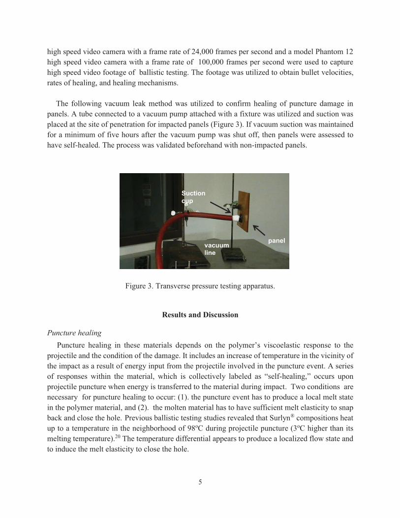
The following vacuum leak method was utilized to confirm healing of puncture damage in panels. A tube connected to a vacuum pump attached with a fixture was utilized and suction was placed at the site of penetration for impacted panels (Figure 3). If vacuum suction was maintained for a minimum of five hours after the vacuum pump was shut off, then panels were assessed to have self-healed. The process was validated beforehand with non-impacted panels. vacuum line vacuum line
Figure 3. Transverse pressure testing apparatus.
Results and Discussion
Puncture healing Puncture healing in these materials depends on the polymer’s viscoelastic response to the projectile and the condition of the damage. It includes an increase of temperature in the vicinity of the impact as a result of energy input from the projectile involved in the puncture event. A series of responses within the material, which is collectively labeled as “self-healing,” occurs upon projectile puncture when energy is transferred to the material during impact. Two conditions are necessary for puncture healing to occur: (1). the puncture event has to produce a local melt state in the polymer material, and (2). the molten material has to have sufficient melt elasticity to snap back and close the hole. Previous ballistic testing studies revealed that Surlyn® compositions heat up to a temperature in the neighborhood of 98oC during projectile puncture (3oC higher than its melting temperature).20 The temperature differential appears to produce a localized flow state and to induce the melt elasticity to close the hole.
vacuum line
Suction cup
panel

6
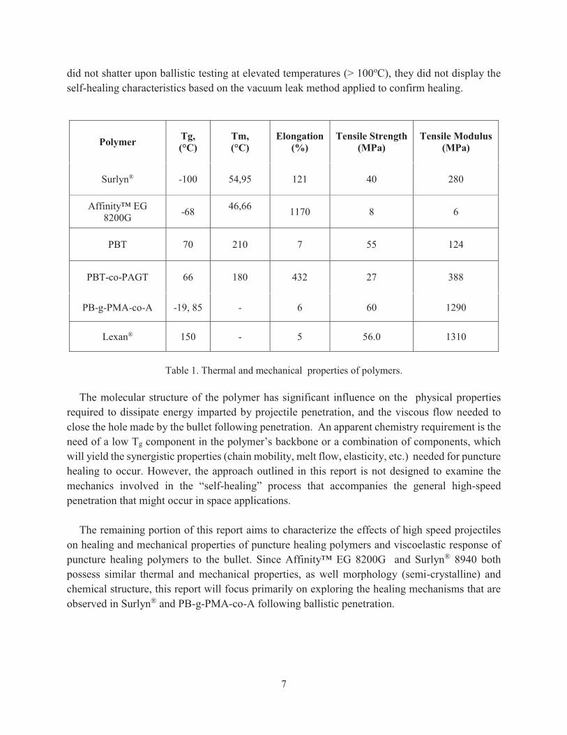
Survey of commercially available polymers Surlyn® is 95% ethylene, 5% methacrylic acid, with a small percentage of the methacrylic acid component neutralized with sodium counterions. A soft, flexible segment in poly(ethylene) and a hard segment in poly(methacrylic acid) make up the copolymer backbone of Surlyn®. While ionic content is not necessary for self-healing, it has been demonstrated to have profound impact on the mechanical properties of ionomers18,19 and contributes to the quality of self-healing.20-23 The material’s viscoelastic response to the puncture event, as determined by molecular structure in relation to physical properties i.e. chain mobility, elasticity, etc. is believed to play a significant role in damage recovery. To further elucidate this point, various commercially available polymers were selected based on this rationale and subjected to ballistic testing. Polymer parameters considered were chemical structure, tensile strength, tensile modulus, glass transition temperature, melting temperature and crystallinity. The semi-crystalline polymers selected for these studies were Surlyn® 8940, Affinity™ EG8200G, poly(butylene terephthalate) PBT, and poly(butylene terephthalate)-co-poly(alkylene glycol terephthalate) PBT-co-PAGT. The amorphous polymers selected were Lexan® and poly(butadiene)-grafted-poly(methyl acrylate-co-acrylonitrile) PB-g-PMA-co-A. The polymers were characterized by DMA, DSC, and mechanical testing (See Table 1). The sequential series of events called “self-healing” led to the closure of the damaged site. A leak detection test described in the Methods section verified closure of the puncture. Puncture healing was observed in semi-crystalline polymers Surlyn® and Affinity™ EG 8200G and the amorphous polymer PB-g-PMA-co-A. Surlyn® and Affinity™ EG8200G, both poly(ethylene) based copolymers (Affinity EG8200G is a non-ionic polymer), self-heal upon ballistic testing at ambient temperature (~24oC).20, 25 Self-healing in Surlyn® and Affinity™ EG8200G, is believed to occur due to: (1). chain mobility needed to ensure self- healing, because test temperatures are above glass transition temperatures (Tg) of both polymers, -100oC and - 68oC, respectively, (2). the polyethylene segment imparts the ability to flow at the temperature tested due to its low melting temperatures and the melt elasticity needed to snap back and close the hole for both polymers. Additionally, PB-g-PMA-co-A self-heals upon ballistic test at temperatures greater than 50oC. The backbone of PB-g-PMA-co-A has an elastic graft segment in poly(butadiene) (6.9%) and a tough segment in poly(methyl acrylate-co-acrylonitrile), which imparts the elasticity to snap back and close the hole and ability to flow at elevated test temperatures. PB-g-PMA-co-A does not puncture heal at 25oC. This is due in part to its glass transition temperature (85oC ) being more than 50°C above the test temperature. An increase in test temperature allows the polymer chains to move, thus providing the chain mobility needed to dissipate the energy imparted by bullet impact. Poly(butylene terephthalate) PBT, poly(butylene terephthalate)-co-poly(alkylene glycol terephthalate) PBT-co-PAGT, and Lexan® do not self-heal, but shatter upon ballistic penetration executed as outlined in this report. PBT and PBT-co-PAGT, brittle semi-crystalline polymers, and Lexan®, a tough amorphous polymer, are thought to have shattered due to lack of chain mobility and elasticity in these materials at test temperatures well below their respective glass transition temperature, Tg, (80- 150oC) and high melting temperatures, Tm, (>200oC). While these polymers
7
did not shatter upon ballistic testing at elevated temperatures (> 100oC), they did not display the self-healing characteristics based on the vacuum leak method applied to confirm healing.
Polymer Tg, (°C)
Tm, (°C)
Elongation (%)
Tensile Strength (MPa)
Tensile Modulus (MPa)
Surlyn® -100 54,95 121 40 280
Affinity™ EG 8200G -68 46,66
1170 8 6
PBT 70 210 7 55 124
PBT-co-PAGT 66 180 432 27 388
PB-g-PMA-co-A -19, 85 - 6 60 1290
Lexan® 150 - 5 56.0 1310
Table 1. Thermal and mechanical properties of polymers.
The molecular structure of the polymer has significant influence on the physical properties
required to dissipate energy imparted by projectile penetration, and the viscous flow needed to close the hole made by the bullet following penetration. An apparent chemistry requirement is the need of a low Tg component in the polymer’s backbone or a combination of components, which will yield the synergistic properties (chain mobility, melt flow, elasticity, etc.) needed for puncture healing to occur. However, the approach outlined in this report is not designed to examine the mechanics involved in the “self-healing” process that accompanies the general high-speed penetration that might occur in space applications.
The remaining portion of this report aims to characterize the effects of high speed projectiles
on healing and mechanical properties of puncture healing polymers and viscoelastic response of puncture healing polymers to the bullet. Since Affinity™ EG 8200G and Surlyn® 8940 both possess similar thermal and mechanical properties, as well morphology (semi-crystalline) and chemical structure, this report will focus primarily on exploring the healing mechanisms that are observed in Surlyn® and PB-g-PMA-co-A following ballistic penetration.
8
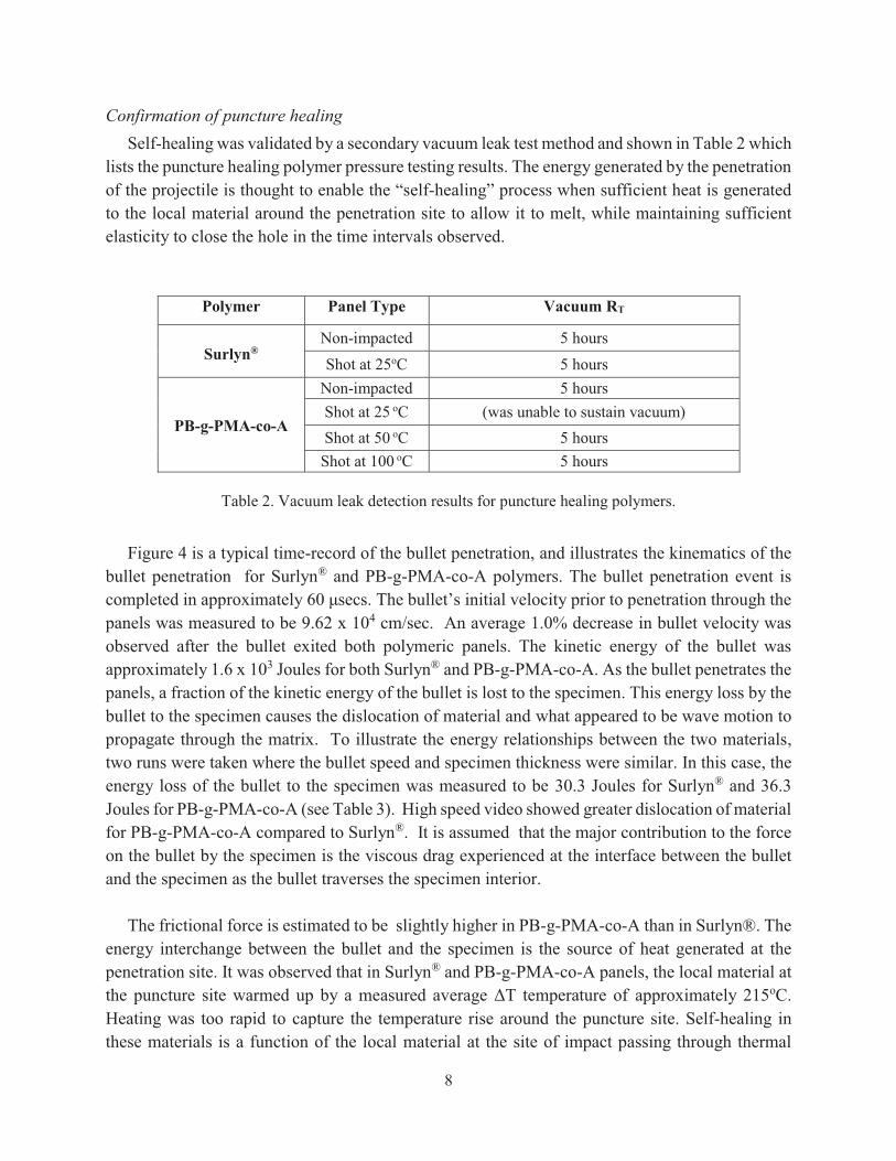
Confirmation of puncture healing Self-healing was validated by a secondary vacuum leak test method and shown in Table 2 which lists the puncture healing polymer pressure testing results. The energy generated by the penetration of the projectile is thought to enable the “self-healing” process when sufficient heat is generated to the local material around the penetration site to allow it to melt, while maintaining sufficient elasticity to close the hole in the time intervals observed.
Polymer Panel Type Vacuum RT
Surlyn®
Non-impacted 5 hours Shot at 25oC 5 hours
PB-g-PMA-co-A
Non-impacted 5 hours Shot at 25 oC (was unable to sustain vacuum) Shot at 50 oC 5 hours Shot at 100 oC 5 hours
Table 2. Vacuum leak detection results for puncture healing polymers.
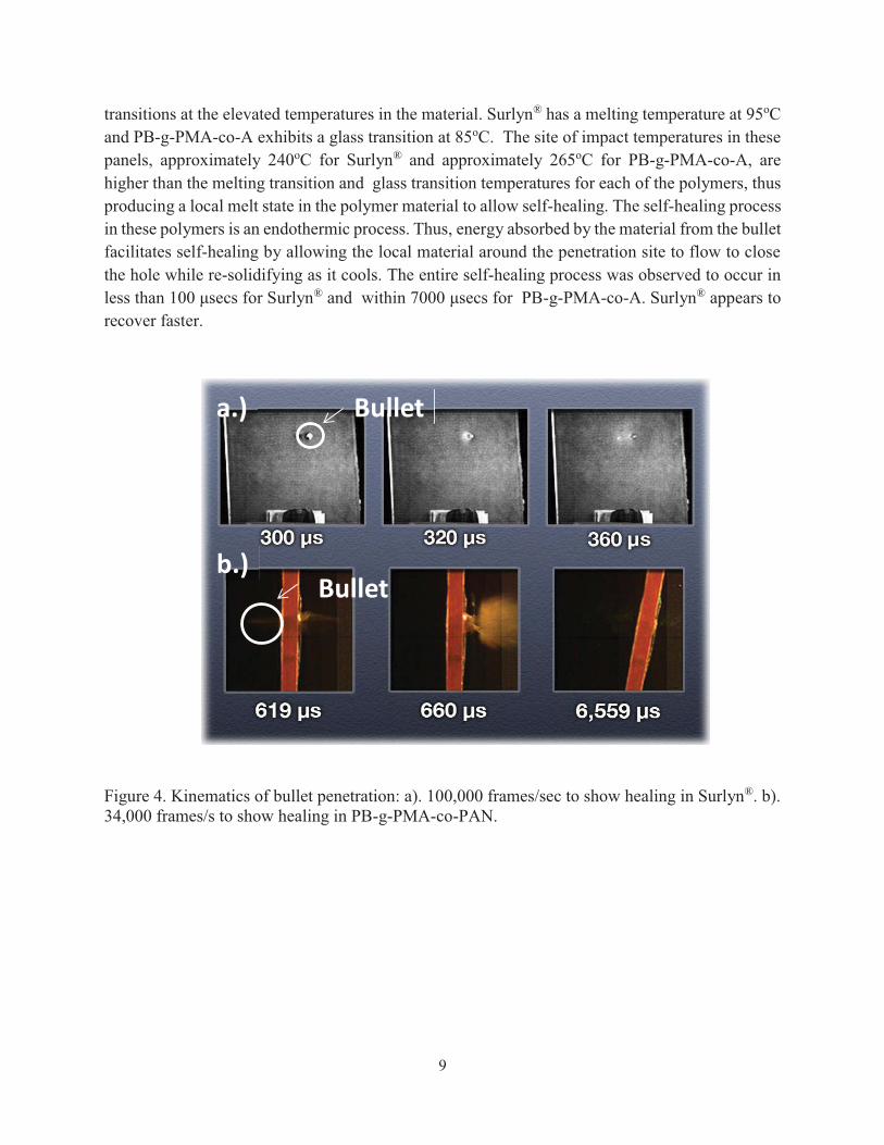
Figure 4 is a typical time-record of the bullet penetration, and illustrates the kinematics of the bullet penetration for Surlyn® and PB-g-PMA-co-A polymers. The bullet penetration event is completed in approximately 60 μsecs. The bullet’s initial velocity prior to penetration through the panels was measured to be 9.62 x 104 cm/sec. An average 1.0% decrease in bullet velocity was observed after the bullet exited both polymeric panels. The kinetic energy of the bullet was approximately 1.6 x 10³ Joules for both Surlyn® and PB-g-PMA-co-A. As the bullet penetrates the panels, a fraction of the kinetic energy of the bullet is lost to the specimen. This energy loss by the bullet to the specimen causes the dislocation of material and what appeared to be wave motion to propagate through the matrix. To illustrate the energy relationships between the two materials, two runs were taken where the bullet speed and specimen thickness were similar. In this case, the energy loss of the bullet to the specimen was measured to be 30.3 Joules for Surlyn® and 36.3 Joules for PB-g-PMA-co-A (see Table 3). High speed video showed greater dislocation of material for PB-g-PMA-co-A compared to Surlyn®. It is assumed that the major contribution to the force on the bullet by the specimen is the viscous drag experienced at the interface between the bullet and the specimen as the bullet traverses the specimen interior. The frictional force is estimated to be slightly higher in PB-g-PMA-co-A than in Surlyn®. The energy interchange between the bullet and the specimen is the source of heat generated at the penetration site. It was observed that in Surlyn® and PB-g-PMA-co-A panels, the local material at the puncture site warmed up by a measured average ΔT temperature of approximately 215oC. Heating was too rapid to capture the temperature rise around the puncture site. Self-healing in these materials is a function of the local material at the site of impact passing through thermal
9
transitions at the elevated temperatures in the material. Surlyn® has a melting temperature at 95oC and PB-g-PMA-co-A exhibits a glass transition at 85oC. The site of impact temperatures in these panels, approximately 240oC for Surlyn® and approximately 265oC for PB-g-PMA-co-A, are higher than the melting transition and glass transition temperatures for each of the polymers, thus producing a local melt state in the polymer material to allow self-healing. The self-healing process in these polymers is an endothermic process. Thus, energy absorbed by the material from the bullet facilitates self-healing by allowing the local material around the penetration site to flow to close the hole while re-solidifying as it cools. The entire self-healing process was observed to occur in less than 100 μsecs for Surlyn® and within 7000 μsecs for PB-g-PMA-co-A. Surlyn® appears to recover faster.
Figure 4. Kinematics of bullet penetration: a). 100,000 frames/sec to show healing in Surlyn®. b). 34,000 frames/s to show healing in PB-g-PMA-co-PAN.
Bullet
Bullet
a.)
b.)

10
Speci pSpecimen
Bulletet
Material
Speed Initial
(x102m/sec)
Initial Kinetic Energy (x103
Joules)
Energy lost by
bullet to Specimen (Joules)
Fractional Energy imparted to Specimen
(x10-2))
Surlyn® 9.67 1.67 30.3 1.82
PB-g-PMA-co-A 9.70 1.67 36.6 2.19
Table 3. Summary of kinematic and energy loss for the two panels under similar test conditions.
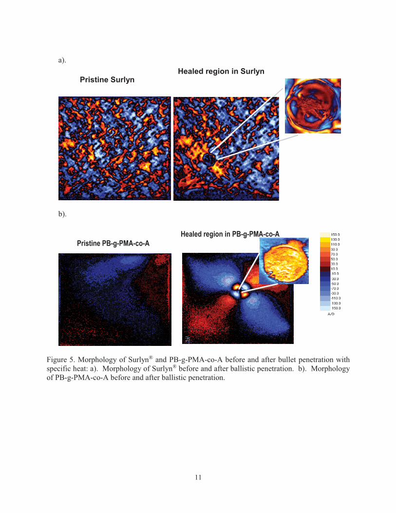
Grey-field Polariscope measurements and Specific heat The Grey-field Polariscope, described in the Appendix provides information that leads to additional insight into the healing mechanism for Surlyn® and PB-g-PMA-co-A by giving a response to strain fields left at the sites from the bullet penetration. These effects were recorded around regions surrounding damage sites in a polymer, which is photo-responsive to polarized light. The degree of responsiveness has been shown to be directly related to the magnitude and extent of the strain field in both PB-g-PMA-co-A and Surlyn®. In the case of Surlyn, the crystalline structure, including crystal orientation is superimposed on the strain field. Figure 5 shows the morphology of Surlyn® and PB-g-PMA-co-A before and after penetration along with specific heats for the respective polymers. With regards to the sequence of events following ballistic puncture, specific heats directly correlate changes in temperature with molecular events such as crystallinity and residual stresses. Surlyn® has a Cp = 4.5 J/gmoK and PB-g-PMA-co-A has a Cp = 2.2 J/gmoK (See Figure 6). The scales in the figures are a measure of the photoelastic retardation in both polymers. The crystal structure has an axis along which the speed of light changes, and shows as a structure with various hues that depend on interference effects from the “ordinary ray” and the “extraordinary ray” that passes through the crystal. This effect is an example of retardation, and can result in the generation of many hues.26 This pattern is superimposed on the stress field pattern. The elastic strain field from the plastic deformation caused by the bullet penetration extends well beyond the immediate damage site. Hence, two parts to the strain fields are considered. The first is close to the damage site, and is largely due to plastic deformation – related effects in the polymers from the projectile which affect local volume. Away from the damage site, there is an elastic strain field caused by this volume change. While this field is smaller, it extends for some distance from the damage site.
11
a).
b).
Figure 5. Morphology of Surlyn® and PB-g-PMA-co-A before and after bullet penetration with specific heat: a). Morphology of Surlyn® before and after ballistic penetration. b). Morphology of PB-g-PMA-co-A before and after ballistic penetration.
Pristine Surlyn Healed region in Surlyn
Pristine PB-g-PMA-co-A Healed region in PB-g-PMA-co-A

12
Figure 6. Specific heats of Surlyn® and PB-g-PMA-co-A.
13
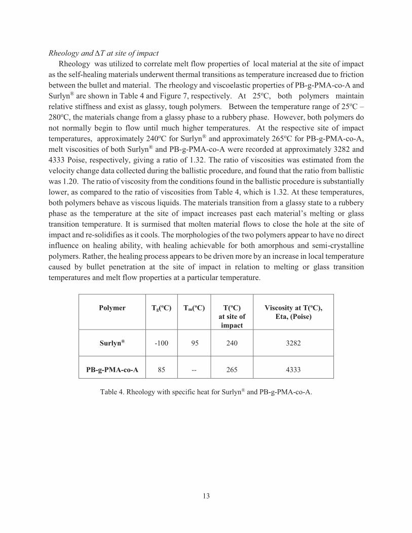
Rheology and ∆T at site of impact Rheology was utilized to correlate melt flow properties of local material at the site of impact as the self-healing materials underwent thermal transitions as temperature increased due to friction between the bullet and material. The rheology and viscoelastic properties of PB-g-PMA-co-A and Surlyn® are shown in Table 4 and Figure 7, respectively. At 25oC, both polymers maintain relative stiffness and exist as glassy, tough polymers. Between the temperature range of 25oC – 280oC, the materials change from a glassy phase to a rubbery phase. However, both polymers do not normally begin to flow until much higher temperatures. At the respective site of impact temperatures, approximately 240oC for Surlyn® and approximately 265oC for PB-g-PMA-co-A, melt viscosities of both Surlyn® and PB-g-PMA-co-A were recorded at approximately 3282 and 4333 Poise, respectively, giving a ratio of 1.32. The ratio of viscosities was estimated from the velocity change data collected during the ballistic procedure, and found that the ratio from ballistic was 1.20. The ratio of viscosity from the conditions found in the ballistic procedure is substantially lower, as compared to the ratio of viscosities from Table 4, which is 1.32. At these temperatures, both polymers behave as viscous liquids. The materials transition from a glassy state to a rubbery phase as the temperature at the site of impact increases past each material’s melting or glass transition temperature. It is surmised that molten material flows to close the hole at the site of impact and re-solidifies as it cools. The morphologies of the two polymers appear to have no direct influence on healing ability, with healing achievable for both amorphous and semi-crystalline polymers. Rather, the healing process appears to be driven more by an increase in local temperature caused by bullet penetration at the site of impact in relation to melting or glass transition temperatures and melt flow properties at a particular temperature.
Polymer
Tg(oC)
Tm(oC)
T(oC)
at site of impact
Viscosity at T(oC),
Eta, (Poise)
Surlyn®
-100
95
240
3282
PB-g-PMA-co-A
85
--
265
4333
Table 4. Rheology with specific heat for Surlyn® and PB-g-PMA-co-A.
14
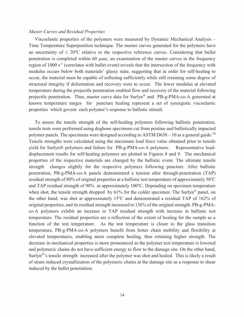
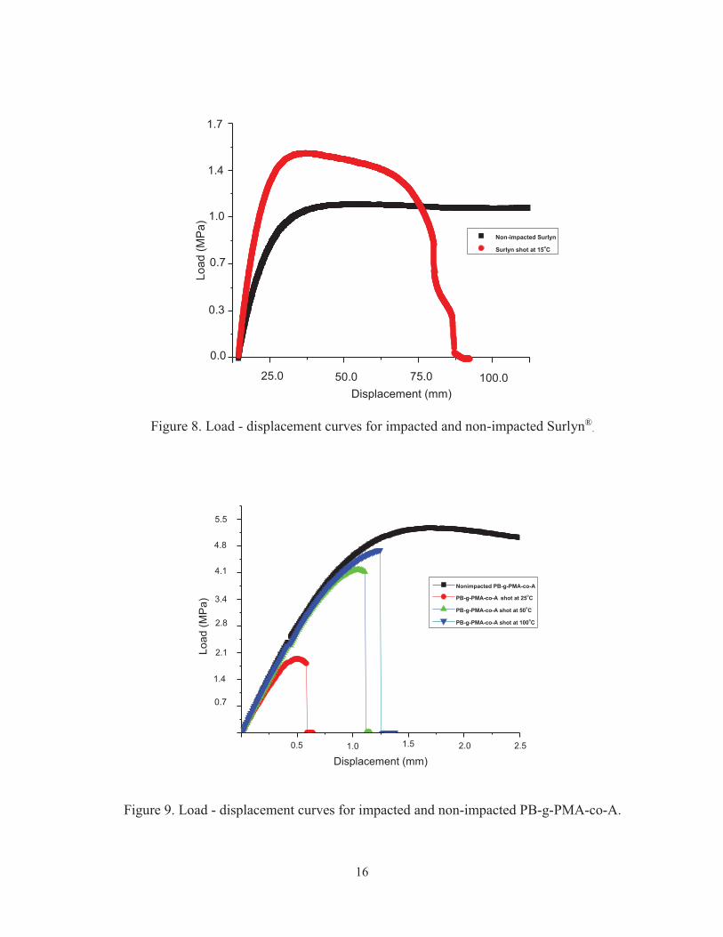
Master Curves and Residual Properties Viscoelastic properties of the polymers were measured by Dynamic Mechanical Analysis – Time Temperature Superposition technique. The master curves generated for the polymers have an uncertainty of � 20oC relative to the respective reference curves. Considering that bullet penetration is completed within 60 µsec, an examination of the master curves in the frequency region of 1000 s-1 (correlates with bullet event) reveals that the intersection of the frequency with modulus occurs below both materials’ glassy state, suggesting that in order for self-healing to occur, the material must be capable of softening sufficiently while still retaining some degree of structural integrity if deformation and recovery were to occur. The lower modulus at elevated temperature during the projectile penetration enabled flow and recovery of the material following projectile penetration. Thus, master curve data for Surlyn® and PB-g-PMA-co-A generated at known temperature ranges for puncture healing represent a set of synergistic viscoelastic properties which govern each polymer’s response to ballistic stimuli. To assess the tensile strength of the self-healing polymers following ballistic penetration, tensile tests were performed using dogbone specimens cut from pristine and ballistically impacted polymer panels. The specimens were designed according to ASTM D638 – 10 as a general guide.24 Tensile strengths were calculated using the maximum load force value obtained prior to tensile yield for Surlyn® polymers and failure for PB-g-PMA-co-A polymers. Representative load-displacement results for self-healing polymers are plotted in Figures 8 and 9. The mechanical properties of the respective materials are changed by the ballistic event. The ultimate tensile strength changes slightly for the respective polymers following puncture. After ballistic penetration, PB-g-PMA-co-A panels demonstrated a tension after through-penetration (TAP) residual strength of 80% of original properties at a ballistic test temperature of approximately 50oC and TAP residual strength of 90% at approximately 100oC. Depending on specimen temperature when shot, the tensile strength dropped by 61% for the colder specimen. The Surlyn® panel, on the other hand, was shot at approximately 15oC and demonstrated a residual TAP of 162% of original properties, and its residual strength increased to 136% of the original strength. PB-g-PMA-co-A polymers exhibit an increase in TAP residual strength with increase in ballistic test temperature. The residual properties are a reflection of the extent of healing for the sample as a function of the test temperature. As the test temperature is closer to the glass transition temperature, PB-g-PMA-co-A polymers benefit from better chain mobility and flexibility at elevated temperatures, enabling more complete healing, thus retaining higher strength. The decrease in mechanical properties is more pronounced as the polymer test temperature is lowered and polymeric chains do not have sufficient energy to flow to the damage site. On the other hand, Surlyn®’s tensile strength increased after the polymer was shot and healed. This is likely a result of strain induced crystallization of the polymeric chains at the damage site as a response to shear induced by the bullet penetration.

15
a). Master curve of Surlyn®.
b). Master curve of PB-g-PMA-co-A.
Figure 7. Master Curves of Surlyn® and PB-g-PMA-co-A.
16
Figure 8. Load - displacement curves for impacted and non-impacted Surlyn®
.
Figure 9. Load - displacement curves for impacted and non-impacted PB-g-PMA-co-A.
Non-impacted Surlyn
Surlyn shot at 15oC
Load
(MPa
)
Displacement (mm)25.0 50.0 75.0
1.7
1.4
1.0
0.7
0.3
0.0
100.0
Nonimpacted PB-g-PMA-co-A
PB-g-PMA-co-A shot at 25oC
PB-g-PMA-co-A shot at 50oC
PB-g-PMA-co-A shot at 100oC
Load
(MP
a)
Displacement (mm)0.5 1.0 1.5 2.0 2.5
5.5
4.8
4.1
3.4
2.8
2.1
1.4
0.7
17
Conclusions
In summary, a class of polymers has been identified that, within the limitations of the tests described herein, show some promise in that they close (“heal”) holes inflicted at the damage site and, once healed, are able to transfer load across the damage site. Under the collision parameters from conducted tests, the materials identified were capable of utilizing the energy involved in the collision event based on dynamic properties imparted by inherent chemistry and without the need of foreign inserts or external stimuli. Such materials or modified versions have the potential for integration into structural self-healing engineered material concepts which may improve overall vehicle safety and reliability, prolong service lifetime, allow lighter structural concepts, and enhance orbital debris damage survivability. What remains after this work is to determine whether the specific conditions from the procedure are sufficient in the general collision case. Time, temperature and stress are variables in each possible collision process. It is possible that collision-based processes induced in a material depend upon collision dynamics, which may be case-dependent. Addressing the issues involved require more theoretical and experimental work on the “self-healing” process, and its effects on the material’s service life parameters, such as fatigue, fracture and local changes in thermal properties.
References 1. Wool, R.P., Polymer Interfaces: Structure and Strength, (Hanser/Gardner, Munich, 1995). 2. White, S.R., Sotto, N.R., Geubelle, P.H., Moore, J.S., Kessler, M.R., Sriram, S.R., Brown,
E.N., Viswanathan, S., Nature, 2001, 409, 794-797. 3. Dry, C., Int. J Mod Phys B, 1992, 6(15-16), 2763-2771. 4. Dry, C., McMillan W., Smart Mater Struct, 1996, 5(3), 297-300. 5. (a). Pang, J.W., Bond, I.P, Composites Part A: Applied Science and Manufacturing, 2005,
36(2), 183-188. (b). Pang, J.W., Bond, I.P., Composites Science and Technology, 2005, 65 (11-12), 1791-1799.
6. White, S.R, Sottos, N.R., K. Toohey, K.., Lewis, J., Moore, J., Nature, 6, 2007, 581-584. 7. John, M., Li, G., Smart Mater Struct, 2010, 19, 075013-075024. 8. Nji, J., Li, G., Smart Mater Struct, 2010, 19, 035007-035015. 9. Meure, S., Furman, S., Khor, S., Macromol Mater Eng., 2010, 295, 420-424. 10. Chen, X., Wudl, F., Mal, A.J., Shen, H., Nutt, S.,R. Macromolecules, 2003, 34, 1902. 11. Chen, X., Dam, M., Ono, K., Mal, A., Shen, H., Nutt, S., Hera, Science, 2002, 295, 1698-
1702. 12. Wojtecki, R., Meador, M., Rowan, S.J., Nature Materials, 2011, 10, 14-27. 13. Cheng, S.; Mather, B. D.; Long, T. E. Polymer Preprints, 2008, 49(1), 978-979. 14. Cordier, P., Tournilhac, F., Soulie´-Ziakovic, C., Leibler,L., Nature, 2008, 451, 977-980. 15. Canadell, J., Goossens, H., Klumperman, B., Macromolecules, 2011, 44, 2536-2541. 16. Burnworth, M., Tang, L., Kumpfer, J., Duncan, A., Beyer, F., Fiore, G., Rowan, S., Weder,
C., Nature, 2011, 472, 334. 17. Deng, G., Tang, C., Li, F., Jiang, H., Chen, Y., Macromolecules, 2010, 43, 1191-1194. 18. Lantman, C.W., Macknight, W.J., Annual Rev. Mat., 1989, 19, 295. 19. Hird, B., Eisenberg, A., Macromolecules, 1992, 25, 6466. 20. Kalista, S., M.S. thesis entitled, “Self- healing thermoplastic poly(ethylene-co-methacrylic
18
acid) Copolymers Following Projectile Puncture,” submitted to the faculty of Virginia Polytechnic Institute and State University, Blacksburg, VA, 2003.
21. Fall, R., M.S. thesis entitled, “Puncture reversal of ethylene ionomers – Mechanistic Studies,” submitted to the faculty of Virginia Polytechnic Institute and State University, Blacksburg, VA, 2001.
22. Varley, R.J., van der Zwaag, S., Acta Materialia, 2008, 56, 5737–5750. 23. Varley, R.J., van der Zwaag, S., Polym Int, 2010, 59, 1031–1038. 24. (a). ASTM D638-10, “Standard Test Method for Tensile Properties of Plastics,” ASTM
International, West Conshohocken, PA, 2010, DOI: 10.1520/D0638-10, www.astm.org; (b). ASTM D5045-14, “Standard Test Methods for Plane-Strain Fracture Toughness and Strain Energy Release Rate of Plastic Materials,” ASTM International, West Conshohocken, PA, 2014, www.astm.org.
25. Klein, D., United States Patent #8,063,171, “Self-healing polymers,” Nov. 22, 2011. 26. Hecht, E., Zajac, A., Optics, (Addison-Wesley Publishing Company, Reading Mass, 1974),
pp. 242-250.
Appendix
Grey-field Polariscope Stress Measurements
The visible light grey-field polariscope (GFP) was originally developed by Stress Photonics,
Inc. for NASA to provide high-resolution full-field subfringe photoelastic stress analysis in
materials transparent to visible light.A1,A2 In photoelasticity, the stress field of a test article is
evaluated through the use of polarized light. The GFP performs this evaluation by combining a
circularly polarized light source with a linearly polarized analyzer. As the analyzer is rotated, data
are acquired with a video camera that uses synchronous (synchronized with the rotation of the
analyzer) demodulation.
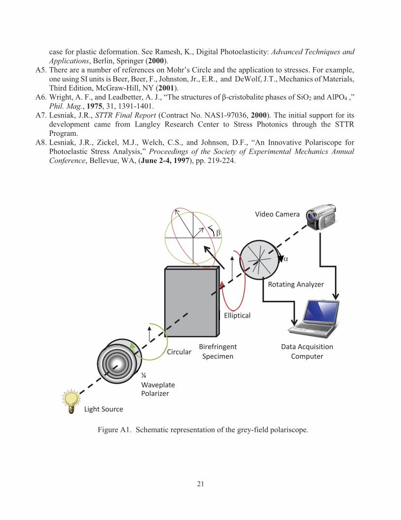
Figure A1 shows a schematic representation of grey-field polariscope using photoelasticity to
inspect a specimen that exhibits birefringence when strained. Circularly polarized light is
represented by two orthogonal linear polarized light vectors that are out of phase by �/2 radians.
It has been shown by Horn A3 that for the GFP configuration described above, the intensity of the
transmitted light is:
(AE1)
where a is amplitude of the circularly polarized light, � is the angular orientation of the analyzer,
� is the orientation of the fast axis of the resulting elliptical light and � is the phase lag of the slow
axis of the ellipse due to the stress-birefringence of the specimen, and k is a constant of
proportionality.A2 When α-β is ±45o, the intensity I= k a2(1±sinΔ). This condition marks the
I �a2(1sin{2(� ��)}sin�)
19
alignment of fast-axis orientation with the analyzer angle (α=β). When α-β is ±45°, the intensity
I= k a2(1± sin∆), which determines ∆ experimentally.
Following the formulation by J. Clerk Maxwell for the elastic case of birefringent retardation
Δ is defined for both cases
(AE2)
where Celastic is the elastic optic coefficient, Cplastic is the plastic optic coefficient, � is the
wavelength of the light, d is the thickness of the plate and 1 and 2 are the first and second
principal stresses.A4 Two cases are the focus of concern. The damage site specifically will have a
plastic rearrangement of atomic structures around it, and a region (far field) surrounding the
damage site where atomic position shifts are elastic. Hence, the stress-optic coefficient as
formulated by Maxwell, is used for both elastic and plastic strains.
By dividing Equation (1) by ka2, and using a trigonometric identity to rewrite the right hand side
in terms of the angular orientation a, one obtains
(AE3)
where
(AE4a)
(AE4b)
and Δ is the birefringent or photoelastic retardation. Typically Δ is referred to as “photoelastic
retardation,” so birefringent or photoelastic retardation will be referred to by the acronym PER.
The first principal strains are related directly to the sine and cosine amplitudes (Ica, Isa) by
(AE5)
(AE6)
� elastic �2�Celastic d
�( 1 � 2)
� plastic �2�Cplasticd
�( 1 � 2)
Ia2
�1 Ica cos2� Isasin2�
Ica � �(sin�)sin2�
Isa � (sin�)cos2�
sin� � Ica2 Isa
2
� �12tan�1 �
IcaIsa
��
����
��
����
20
For most applications of interest, the shear strains encountered are small. Therefore, the optical
retardations are small (subfringe). Therefore, Equation (5) can be simplified further by using the
relationship sin � ≈ �. Equation (5) can be combined with Equation (2) to give:
(AE7)
where C represents either Celastic (for the far-field) or Cplastic (for the near field).
Horn gives a geometric interpretation of equation (7) by using a Mohr’s circle, with a radius of
( 1 - 2)/2 for the case of elastic deformation.A3 This allows for the following relationships to be
directly developed from the sine and cosine intensities (Isa and Ica) discussed above:
(AE8)
(AE9)
The analysis for the elastic case was generated for the commercially developed unit, currently
marketed by Stress Photonics.A5-A8 This laboratory instrument is a transmission system that has a
spatial resolution determined by the diffraction limits of the lens system.
References
A1. Lesniak, J.R., STTR Final Report (Contract No. NAS1-97036, 2000). The initial support for its development came from Langley Research Center to Stress Photonics through the STTR Program.
A2. Lesniak, J.R., Zickel, M.J., Welch, C.S., and Johnson, D.F., “An Innovative Polariscope for Photoelastic Stress Analysis,” Proceedings of the Society of Experimental Mechanics Annual Conference, Bellevue, WA (June 2-4, 1997), pp. 219-224.
A3. Horn, G., Lesniak, J., Mackin, T., Boyce, B., Rev. Sci. Instrum., 2005, 76, 045108, 1-10. A4. Maxwell formulated the relations between the stresses in a material and changes in the indices of
refraction, which can be written in terms of the phase lag (or relative retardation) in a material under elastic (reversible) stress:
where C is the stress optic coefficient, � is the wavelength of the light, d is the thickness of the plate and 1 and 2 are the first and second principal stresses. This form is used to represent the
� �2�Cd
�( 1 � 2)
( 1� 2) ��
2�CdIca2 Isa
2
Isa �( xx � yy)
Ica ��xy[� ( 45 � �45)]
21
case for plastic deformation. See Ramesh, K., Digital Photoelasticity: Advanced Techniques and Applications, Berlin, Springer (2000).
A5. There are a number of references on Mohr’s Circle and the application to stresses. For example, one using SI units is Beer, Beer, F., Johnston, Jr., E.R., and DeWolf, J.T., Mechanics of Materials, Third Edition, McGraw-Hill, NY (2001).
A6. Wright, A. F., and Leadbetter, A. J., “The structures of β-cristobalite phases of SiO2 and AlPO4 ,” Phil. Mag., 1975, 31, 1391-1401.
A7. Lesniak, J.R., STTR Final Report (Contract No. NAS1-97036, 2000). The initial support for its development came from Langley Research Center to Stress Photonics through the STTR Program.
A8. Lesniak, J.R., Zickel, M.J., Welch, C.S., and Johnson, D.F., “An Innovative Polariscope for Photoelastic Stress Analysis,” Proceedings of the Society of Experimental Mechanics Annual Conference, Bellevue, WA, (June 2-4, 1997), pp. 219-224.
Figure A1. Schematic representation of the grey-field polariscope.
Light Source
Polarizer
¼ Waveplate
Circular rBirefringent Specimen
Elliptical
Rotating Analyzer
Video Camera
Data Acquisition Computer
�
�
REPORT DOCUMENTATION PAGE
Standard Form 298 (Rev. 8/98)Prescribed by ANSI Std. Z39.18
Form Approved OMB No. 0704-0188
The public reporting burden for this collection of information is estimated to average 1 hour per response, including the time for reviewing instructions, searching existing datasources, gathering and maintaining the data needed, and completing and reviewing the collection of information. Send comments regarding this burden estimate or any otheraspect of this collection of information, including suggestions for reducing the burden, to Department of Defense, Washington Headquarters Services, Directorate for InformationOperations and Reports (0704-0188), 1215 Jefferson Davis Highway, Suite 1204, Arlington, VA 22202-4302. Respondents should be aware that notwithstanding any otherprovision of law, no person shall be subject to any penalty for failing to comply with a collection of information if it does not display a currently valid OMB control number. PLEASE DO NOT RETURN YOUR FORM TO THE ABOVE ADDRESS.
1. REPORT DATE (DD-MM-YYYY) 2. REPORT TYPE 3. DATES COVERED (From - To)
4. TITLE AND SUBTITLE 5a. CONTRACT NUMBER
5b. GRANT NUMBER
5c. PROGRAM ELEMENT NUMBER
5d. PROJECT NUMBER
5e. TASK NUMBER
5f. WORK UNIT NUMBER
6. AUTHOR(S)
7. PERFORMING ORGANIZATION NAME(S) AND ADDRESS(ES) 8. PERFORMING ORGANIZATION REPORT NUMBER
10. SPONSOR/MONITOR'S ACRONYM(S)
11. SPONSOR/MONITOR'S REPORT NUMBER(S)
9. SPONSORING/MONITORING AGENCY NAME(S) AND ADDRESS(ES)
12. DISTRIBUTION/AVAILABILITY STATEMENT
13. SUPPLEMENTARY NOTES
14. ABSTRACT
15. SUBJECT TERMS
16. SECURITY CLASSIFICATION OF:a. REPORT b. ABSTRACT c. THIS PAGE
17. LIMITATION OF ABSTRACT
18. NUMBER OF PAGES
19a. NAME OF RESPONSIBLE PERSON
19b. TELEPHONE NUMBER (Include area code)(757) 864-9658
NASA Langley Research Center Hampton, VA 23681-2199
National Aeronautics and Space Administration Washington, DC 20546-0001
NASA-TM-2017-219642
L-20545
01-07-2017 Technical Memorandum
STI Help Desk (email: [email protected])
U U U UU
Ballistic; High speed thermal imaging; Self-healing polymers
Ballistic Puncture Self-healing Polymeric Materials
Gordon, Keith L.; Siochi, Emilie J.; Yost, William T.; Bogert, Phil B.; Howell, Patricia A.; Cramer, K. Elliott; Burke, Eric R.
26
NASA
284848.02.04.07.01
UnclassifiedSubject Category 23 Availability: NASA STI Program (757) 864-9658
Space exploration launch costs on the order of $10K per pound provides an incentive to seek ways to reduce structural mass while maintaining structural function to assure safety and reliability. Damage-tolerant structural systems provide a route to avoiding weight penalty while enhancing vehicle safety and reliability. Self-healing polymers capable of spontaneous puncture repair show promise to mitigate potentially catastrophic damage from events such as micrometeoroid penetration. Effective self-repair requires these materials to quickly heal following projectile penetration while retaining some structural function during the healing processes. Although there are materials known to possess this capability, they are typically not considered for structural applications. Current efforts use inexpensive experimental methods to inflict damage, after which analytical procedures are identified to verify that function is restored. Two candidate self-healing polymer materials for structural engineering systems are used to test these procedures.