barnstead e-pure - toolik field station::main...
TRANSCRIPT

1
BARNSTEAD E-pure ®OPERATION MANUAL
AND PARTS LISTSERIES 1090
3 Module E-pure 4 Module E-pureD4631 120 VAC D4641 120 VACD4632-33 230 VAC D4642-33 230 VACD4633 100 VAC D4643 100 VAC
LT1090X2 • 8/25/97
BARNSTEAD|THERMOLYNE CORPORATION
2
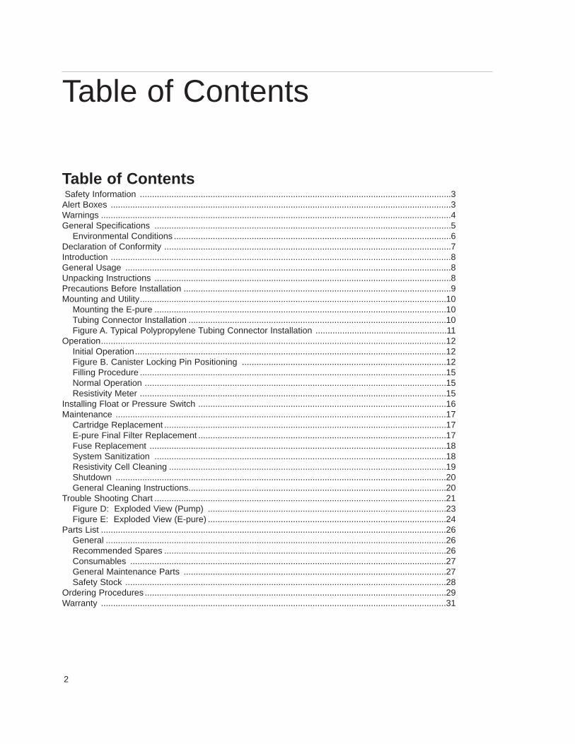
Table of ContentsSafety Information ................................................................................................................................3
Alert Boxes ............................................................................................................................................3 Warnings ................................................................................................................................................4 General Specifications ..........................................................................................................................5
Environmental Conditions ..................................................................................................................6 Declaration of Conformity ......................................................................................................................7 Introduction ............................................................................................................................................8General Usage ......................................................................................................................................8 Unpacking Instructions ..........................................................................................................................8Precautions Before Installation ..............................................................................................................9 Mounting and Utility..............................................................................................................................10
Mounting the E-pure ........................................................................................................................10Tubing Connector Installation ..........................................................................................................10Figure A. Typical Polypropylene Tubing Connector Installation ......................................................11
Operation..............................................................................................................................................12Initial Operation................................................................................................................................12 Figure B. Canister Locking Pin Positioning ....................................................................................12 Filling Procedure ..............................................................................................................................15Normal Operation ............................................................................................................................15 Resistivity Meter ..............................................................................................................................15
Installing Float or Pressure Switch ......................................................................................................16 Maintenance ........................................................................................................................................17
Cartridge Replacement ....................................................................................................................17 E-pure Final Filter Replacement ......................................................................................................17Fuse Replacement ..........................................................................................................................18 System Sanitization ........................................................................................................................18Resistivity Cell Cleaning ..................................................................................................................19 Shutdown ........................................................................................................................................20 General Cleaning Instructions..........................................................................................................20
Trouble Shooting Chart ........................................................................................................................21 Figure D: Exploded View (Pump) ..................................................................................................23 Figure E: Exploded View (E-pure) ..................................................................................................24
Parts List ..............................................................................................................................................26 General ............................................................................................................................................26Recommended Spares ....................................................................................................................26 Consumables ..................................................................................................................................27 General Maintenance Parts ............................................................................................................27Safety Stock ....................................................................................................................................28
Ordering Procedures ............................................................................................................................29 Warranty ..............................................................................................................................................31
Table of Contents

3
Safety InformationYour Barnstead E-pure water purification unit has beendesigned with function, reliability, and safety in mind. It isthe user’s responsibility to install it in conformance withlocal electrical codes. For safe operation, please pay at-tention to the alert boxes throughout the manual.
Safety Information
WarningWarnings alert you to apossibility of personal injury.
CautionCautions alert you to apossibility of damage to theequipment.
NoteNotes alert you to pertinentfacts and conditions.
Alert Signals
4
WarningWater Purification technology employs one or more of the following: Chemicals, electrical devices, mercury va-por lamps, steam and heated vessels. Care should be taken when installing, operating or servicing BarnsteadProducts. Listed below are the specific safety notes pertinent to the Barnstead E-Pure.
To avoid electrical shock, always:1. Use a properly grounded electrical outlet of correct voltage and current handling capacity.2. Ensure that the equipment is connected to electrical service according to local and national electrical
codes. Failure to properly connect may create a fire or shock hazard.3. Do not mount E-pure directly over equipment that requires electrical service. Routine maintenance of this
unit may involve water spillage and subsequent electrical shock hazard if imporperly located.4. For continued protection against possible hazard, replace fuses with same type and rating of fuse.5. Disconnect power supply to equipment before servicing.To avoid personal injure:1. Do not use in the presence of flammable or combustible materials; fire or explosion may result. This de-
vice contains components which may ignite such materials.2. This device is to be used with water feeds only. Sanitizing/cleaning agents must be used in compliance
with instructions in this manual. Failure to comply with the above could result in explosion and personalinjury.
3. Avoid splashing disinfectant solution on clothing or skin. Ensure all piping connections are tight to avoidleakage of chemicals. Always depressurize chemical lines before disassembly. Ensure adequate ventila-tion. Follow carefully the manufacturer’s safety instructions on labels of chemical containers and materialdata sheets.
4. Depressurize the system prior to attempting to remove the canisters.5. Refer servicing to qualified personnel.
Warnings

5
General SpecificationsFeedwaterRequirements
Type (1) Tap, RO, DI, distilled.Pressure Range Gravity feed to 7 kg/cm2 (100 psig)
maximum
Temperature Range 4-49°C(40-120°F)
Product Water
Water Quality (1) Type 1 Reagent Grade Water (RGW) perASTM-D1193, NCCLS-ASC-3, and CAP.
Flow rate (Maximum) (2)Type 1 RGW-Filtered Pressure feed 60 Hz 2.5 lpm
(40 psig inlet min.)50 Hz 2.0 lpm
Gravity feed (12” H2O) 60 Hz 1.5 lpm50 Hz 1.3 lpm
(1) E-pure will product Type I water using pretreated water (RO, DI, Distilled) or high quality tap water, provided feedwater suitability isqualified laboratory analysis and recommended faucet flow rate is maintained.
(2) Flow rates are dependent on operating conditions and filter usage. Flow rates will also depend on filter compaction.
Overall InstalledDimensions
3-moduleWidth 30” (762 mm)Depth 7-1/2” (191 mm)Height 26” (660 mm)
4-moduleWidth 36-1/2” (927 mm)Depth 7-1/2” (191 mm)Height 26”
Operating W eight3-module 27.2 kg (54 lbs.)4-module 32.7 kg (67 lbs.)
Mounting Wall mount with brackets provided.
General Specifications

6
Plumbing Connections
Feedwater Inlet 3/8" OD tubing or 1/4" NPTF
Product Water OutletFor Type I Water 1/2" OD hose barb
Electrical Requirements
Voltage and Frequency (Nominal)100 VAC, 50/60 Hz 85-110 VAC, 47-63 Hz, 1 phase115 VAC, 50/60 Hz 98-127 VAC, 47-63 Hz, 1 phase230 VAC, 50/60 Hz 196-253 VAC, 47-63 Hz, 1 phase
Protection100 VAC service 3 ampere slow blow fuse115 VAC service 3 ampere slow blow fuse230 VAC service 2 ampere slow blow fuse
Resistivity Measurement
Range 0.01-18.3 megohm-cm [temperature compensated to 25°C (77°F.)]
Accuracy ± 3% FS
Cell 0.1 constant
Environmental Conditions Operating: 17°C - 27°C; 20% to 80% relative humidity, non-condensing. Installation Category II (over-voltage) in accordance with IEC 664. Pollution Degree 2 in accordance with IEC 664.
Altitude limit: 2,000 meters.Storage: -25°C to 65°C; 20% to 80% relative humidity.
GENERAL SPECIFICATIONS

7
Declaration of Conformity (-33 models only)Barnstead|Thermolyne hereby declares under its sole responsibility that this product conforms with the tech-nical requirements of the following standards:
EMC: EN 50081-1 Generic Emission Standard; EN 50082-1 Generic Immunity Standard;Safety: IEC 1010-1-92 Safety requirements for electrical equipment for measurement, control, and laboratory use; Part I: General Requirements
per the provisions of the Electromagnetic Compatability Directive 89/336/EEC, as amended by 92/31/EECand 93/68/EEC, and per the provisions of the Low Voltage Directive 73/23/EEC, as amended by 93/68/EEC.
The authorized representative located within the European Community is:European ManagerBarnstead|ThermolyneSaarbrückener Str. 248D-38116 BraunschweigGermany
Copies of the Declaration of Conformity are available upon request.
Declaration of Conformity
8
IntroductionIt is the user’s responsibility to read and to understand thecontents of this manual prior to installation and use of thisequipment.
The manual contains the information you will need to in-stall, operate and maintain the E-pure cartridge deioniza-tion system manufactured by Barnstead/Thermolyne Cor-poration.
The E-pure is designed to produce Type 1 reagent gradewater equal to or exceeding standards established byASTM, CAP and NCCLS.
Careful attention to the following instructions will assurethat the E-pure runs properly and produces water to speci-fication.
General UsageDo not use this product for anything other than its intendedusage.
Unpacking InstructionsUnpack the E-pure carefully. Ensure that all componentsare removed prior to discarding packaging. The wall brack-et can be removed and used as a mounting template. Addi-tional parts included with your unit, but not attached to theunit are as follows: 1 - TU550X5 Tubing; 1 - 03039 Adapter,placed on tubing and 3 or 4 - GSX28 O-rings.
Introduction

9
Precautions BeforeInstallationThe E-pure deionization system can be used on pre-treated or high quality tap water. Some municipal tapwater supplies contain a very high concentration of sus-pended particles, colloids, and dissolved organic and in-organic materials that should be removed by pretreat-ment before the water is processed by the E-pure. The4-module unit is typically used with tap water. The 3-module unit is typically used with water pretreated byreverse osmosis, distillation or deionization. If you planto use a tap water feed for your E-pure, Barnsteadencourages the use of our water analysis service to veri-fy feedwater suitability. A sample collection kit may beobtained by contacting Barnstead/Thermolyne or yourpreferred laboratory supply dealer.
The E-pure requires expendable pretreatment anddeionization cartridges and final filters which are notsupplied with the unit and must be purchased separately.These expendables are available as individual compo-nents or in Expendable Kits. See Table 2 on page 12 forkit listings.
Your E-pure is supplied with a pre-wired jumper in the“pump interlock” connector. Installation of optionsD0603, D0606 (Float Switch) or D2706 (PressureSwitch) require removal of this jumper plug. DO NOTdiscard this plug, it will be needed for certain mainte-nance operations.
On 100 VAC, 115 VAC and 230 VAC models a powercord is provided with a plug to be connected to a stan-dard grounded electrical outlet. The power cord on E-pure is color coded to CEE* specifications. (Table 1)
Precautions Before Installation
Table 1. POWER CORD COLOR CODECEE* Color Coding North American Standard Color CodingFunctionLight Blue White N - NeutralBrown Black L - LiveGreen/Yellow Green or Green Yellow E - Earth or Ground*International Commission on Rules for the Approval of Electrical Equipment
10
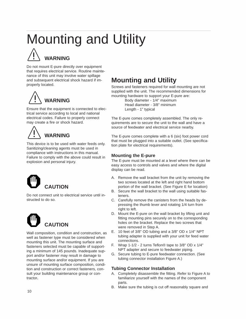
Mounting and UtilityScrews and fasteners required for wall mounting are notsupplied with the unit. The recommended dimensions formounting hardware to support your E-pure are:
Body diameter - 1/4" maximumHead diameter - 3/8" minimumLength - 1” typical
The E-pure comes completely assembled. The only re-quirements are to secure the unit to the wall and have asource of feedwater and electrical service nearby.
The E-pure comes complete with a 6 (six) foot power cordthat must be plugged into a suitable outlet. (See specifica-tion plate for electrical requirements).
Mounting the E-pureThe E-pure must be mounted at a level where there can beeasy access to controls and valves and where the digitaldisplay can be read.
A. Remove the wall bracket from the unit by removing thetwo screws located at the left and right hand bottomportion of the wall bracket. (See Figure E for location)
B. Secure the wall bracket to the wall using suitable fas-teners.
C. Carefully remove the canisters from the heads by de-pressing the thumb lever and rotating 1/4 turn fromright to left.
D. Mount the E-pure on the wall bracket by lifting unit andfitting mounting pins securely on to the correspondingholes on the bracket. Replace the two screws thatwere removed in Step A.
E. 10 feet of 3/8" OD tubing and a 3/8" OD x 1/4" NPTtubing adapter is supplied with your unit for feed waterconnections.
F. Wrap 1-1/2 - 2 turns Teflon® tape to 3/8" OD x 1/4"NPT adapter and secure to feedwater piping.
G. Secure tubing to E-pure feedwater connection. (Seetubing connector installation Figure A.)
Tubing Connector InstallationA. Completely disassemble the fitting. Refer to Figure A to
familiarize yourself with the names of the componentparts.
B. Make sure the tubing is cut off reasonably square and
Mounting and UtilityWARNING
Do not mount E-pure directly over equipmentthat requires electrical service. Routine mainte-nance of this unit may involve water spillageand subsequent electrical shock hazard if im-properly located.
WARNING
Ensure that the equipment is connected to elec-trical service according to local and nationalelectrical codes. Failure to properly connectmay create a fire or shock hazard.
WARNING
This device is to be used with water feeds only.Sanitizing/cleaning agents must be used incompliance with instructions in this manual.Failure to comply with the above could result inexplosion and personal injury.
CAUTION
Do not connect unit to electrical service until in-structed to do so.
CAUTION
Wall composition, condition and construction, aswell as fastener type must be considered whenmounting this unit. The mounting surface andfasteners selected must be capable of support-ing a minimum of 145 pounds. Inadequate sup-port and/or fastener may result in damage tomounting surface and/or equipment. If you areunsure of mounting surface composition, condi-tion and construction or correct fasteners, con-sult your building maintenance group or con-tractor.
11
that no plastic burrs or ridges are present.C. Place the grab ring and back up ring in the hex nut
in the order and orientation shown in Figure A.Thread the nut onto the connector. DO NOT use theO - ring at this time.
D. Push the tubing through the nut until it bottoms outin the connector.
E. Remove the adapter nut and tubing. Place the O -ring over the tubing. Be careful not to push the back-ing ring or grab ring further back on the tubing wheninstalling the O - ring.
F. Install the hex nut on the connector and hand tight-en.
G. Repeat above steps when securing tubing to the E-pure.
CAUTION
It does not require much force to effect a watertight seal. Over tightening of the adapter will cre-ate damage and subsequent leakage.
NOTE
It is recommended that the customer supply afeedwater shut off valve to interrupt water to theunit when cartridge replacement is necessary.
CAUTION
Do not tighten tube fitting hex nut with a wrench.Tight connections can be made by hand.
Teflon® registered trademark of Dupont
MOUNTING AND UTILITY
Figure A. Typical Polypropylene T ubing Connector Installation

12
OperationInitial OperationInstall the cartridges as follows:
(Refer to TABLE 2 for correct left to right cartridge se-quence.)
A. Remove the protective plastic bag from the cartridges.B. Install D0835 or D0836 pretreatment cartridge into can-
ister #1. Ensure the small hole is on the top and thelarger hole is on the bottom.
C. Install the canister, including cartridge, on head #1(closest to pump cabinet).
Operation
NOTE
Because of the fragile nature of the macroretic-ular resin used in the D0835 and D0836Pretreatment Cartridges, it is possible that ship-ment may have caused fracturing of some ofthe resin particles. Resin fracturing will not de-grade cartridge performance. However, it mayreduce system performance as evidenced bypremature clogging of the Final Filter. To insureoptimum system performance and to preventpremature filter clogging, it is recommendedthat the D0835 and D0836 PretreatmentCartridge be rinsed to remove any fine parti-cles. Install only the Pretreatment Cartridge inthe first canister and run water to drain for tenminutes.
NOTE
Check to be sure O-rings are in place in thecanister and inside the head and are not dam-aged prior to installation. Do not install the re-maining cartridges and final filter at this time.
Figure B. Canister Locking Pin Positioning
13
D. Replace remaining canisters on heads.E. Open inlet valve and place the power switch to the
“ON” position.F. Open drawoff valve to facilitate air removal from the
systemG. Allow the unit to run to drain for ten minutes.H. Turn power to unit off. Close Inlet Valve.I. Remove the empty canisters, drain the water and in-
stall the remaining cartridges per Table 2.J. Open inlet valve and turn power “ON” and run the
first ten liters of water to drain.
CAUTION
Secure Locking Pin before operating.
NOTE
An extra set of head-to-canister O-rings are sup-plied. These can be used to replace any O-ringsthat may have been damaged or deformed inshipment.
CAUTION
Do not run the pump dry; dry running will damagethe pump. Always make sure you have an ade-quate volume of feedwater.
WARNING
Depressurize the system prior to attempting to re-move the canisters.
NOTE
The correct sequence of cartridges is important inproducing the desired quality of water.
OPERATION

14
Table 2 Correct Cartridge Sequence(left to right)
3 Module T ype 1 Cat. No. D5029 3 Module ORGANICfree Cat. No. D5022
1. D0835-Pretreatment 1. D0836-MACROpure2. D5027-ULTRApure DI SG 2. D5027-ULTRApure DI SG3. D5027-ULTRApure DI SG 3. D5021-ORGANICfree
4 Module T ype 1 Cat. No. D5028 4 Module ORGANICfree Cat. No. D5023
1. D0835-Pretreatment 1. D0836-MACROpure2. D0803-High Capacity 2. D0803-High Capacity3. D5027-ULTRApure DI SG 3. D5027-ULTRApure DI SG4. D5027-ULTRApure DI SG 4. D5021-ORGANICfree
4 Module T ype 1 Pretreat Feed 4 Module ORGANICfree Pretreat Feed Cat. No. D50227 Cat. No. D50228
1. D0835-Pretreatment 1. D0836-MACROpure2. D0809-ULTRApure SPG 2. D0809-ULTRApure SPG3. D5027-ULTRApure DI SG 3. D5027-ULTRApure DI SG4. D5027-ULTRApure DI SG 4. D5021-ORGANICfree
OPERATION
15
Filling ProcedureAfter every cartridge exchange, some air will be trappedin the system. Air should be purged before routine use,by the following procedure.
A. Place a container or suitable drain under the drawoffblock.
B. Open all inlet valves and the drawoff valve (handlein vertical position).
C. Plug the unit into the electrical service.D. Place Power Switch to the “ON” position.E. When there is a steady flow from the drawoff valve,
close drawoff valve.F. Check all fittings for leaks and tighten as necessary.G. Install the final filter into the drawoff valve as follows:
1. Tape 11/2 - 2 turns Teflon tape around threadedportion of filter.2. Carefully screw final filter into drawoff valve. Holddrawoff valve to prevent it from turning.
H. Allow the pump to recirculate water before withdraw-ing any water from the unit. During this recirculation,the digital display will register a gradual improve-ment of water quality indicating that the ionexchange cartridges are functioning properly. Afterdesired resistivity is reached, open the drawoff valveand discard about two liters (1/2 gallon) of water intoa container to rinse the filter. For critical applicationssuch as H.P.L.C., rinse 50-100 ml of water throughthe filter prior to using the water
E-pure is ready to deliver Type 1 reagent grade water.
Normal OperationIt is recommended that the pump be left operating duringthe normal workday to eliminate the need of rinsing theunit up to purity each time product water is required fromthe unit.
Resistivity MeterThe D2769 and 2770 are in-line digital read out metersand integral cells that calculate the resistivity in the E-pure®. The resistivity meter measures the specific resis-tance of the water on a scale of 0.1 to 18.3 megohm-cm.The resistivity measurement is automatically tempera-ture compensated to 25°C regardless of system watertemperature.
CAUTION
Do not run the pump dry; dry running will damagethe pump. Always make sure you have an ade-quate volume of feedwater.
CAUTION
Do not tighten filter with a wrench. Tight connec-tions can be made by hand.
OPERATION

16
Installing Float or PressureSwitchAccessories D0603, D0606 (float switches) and D2706(pressure switch) are designed to protect the E-pure pumpby alerting the E-pure of an inadequate feedwater conditionso pump can be shut down. Use the following instructionsfor installation.
1. Disconnect electrical power.2. Remove pump interlock from left side of pump cabinet
and save for future use.3. If using D0603 or D0606 float switch, follow installa-
tion instructions included with unit for installation totank or water line.
4. If using D2706 low pressure switch, install a 1/2" PVCtee (supplied) in incoming water line (see Figure C).Screw the switch into the top of the “T” and inlet tub-ing to NANOpure into remaining openings.
5. Route cable from float or low pressure switch to E-pure.
6. Plug cable into jumper plug outlet.
Installing Float or PressureSwitch
Figure C: Pump Protector Installation
OPTIONAL LOW PRESSURESWITCH CAT. NO. D2706
NON-PRESSUREFEEDWATER TANK
OPTIONAL FLOAT SWITCHCAT. NO. D0603 (115 VAC)CAT. NO. D0606 (230 VAC)1/2" NPT PUMP INTERLOCK
FUNCTION
17
Maintenance
Cartridge ReplacementWhen the resistivity of the water drops below the desiredlevel, replace all cartridges with new cartridges.
A. Disconnect power to the system.B. Close the shutoff valve on the inlet side of the sys-
tem.C. Place a customer-supplied container under the final
filter and open the drawoff valve to depressurize thesystem. Close the drawoff valve.
D. Place a container under the cartridge canister to col-lect any spillage.
E. Carefully remove the canister from the head by de-pressing the thumb lever and rotating 1/4 turn fromright to left. Drain the canister into the container andremove the exhausted cartridge.
F. Inspect the O-rings at the top of the canister and in-side the head and replace if worn.
G. Install new cartridges as explained in INITIAL OP-ERATION.
E-pure Final Filter ReplacementIt is recommended that the final filter be replaced every15 working days, when there is an unacceptable highbacteria passage or when flow decreases to less than 1liter per minute.
To replace the final filter, follow instructions on page 12Step G.
Always run at least 2 liters (1/2 gallon) of deionizedwater through a new filter after installation.
Maintenance
WARNING
Disconnect power supply to equipment beforeservicing.
Refer servicing to qualifying personnel.
WARNING
Depressurize the system prior to attempting to re-move the canisters.

18
Fuse ReplacementA. Disconnect power to the system.B. Remove the front cover of the pump cabinet by remov-
ing the four screws that secure it to the cabinet. Thereare two located on the right and left hand side portion.The front cover is secured to the cabinet by a hinge onthe bottom.
C. Remove the plate located above the pump and motorby removing the four screws that secure the plate. Thiswill expose the fuses and holder. (See Exploded ViewFigure D, page 20)
D. Replace fuses.E. Reassemble plate and resecure front panel.
System SanitizationFrequency of sanitization is difficult to determine becauseof the wide variety of feedwater supplies which can beused, but the need for sanitization can be easily deter-mined. Whenever cartridges are replaced, the systemshould be sanitized by using the new, easy-to-use sanitiza-tion cartridge (#D50223).
Sanitize your E-Pure as follows:A. Turn system off and disconnect power.B. Shut off feedwater valve. Open the drawoff valve to de-
pressurize system prior to attempting to remove canis-ters.
C. Remove the canisters by depressing the thumb leverand rotating 1/4 turn to the left. Discard used cartridg-es. With the cartridges removed from the canisters,wash the inside of the canisters and the inside headswith soap or detergent, using a sponge or clean cloth.Rinse out the canisters and the heads with clean waterseveral times to remove the detergent residues.
D. Remove the 0.2 Micron Final Filter from the drawoffvalve. Do not attempt to sanitize the 0.2 Micron FinalFilter with chemical solutions.
E. Place the sanitizing cartridge (D50223) containing thechlorine pellet onto the head of position number one.
F. Install the three or four canisters onto the heads by de-pressing the thumb lever and rotating the handle ring1/4 turn to the right.
G. Place a suitable container under the drawoff valve tocatch the sanitizing solution. Open the drawoff valve.Turn on the water supply and power to the unit.
WARNING
Disconnect power supply to equipment beforeservicing.
Refer servicing to qualifying personnel.
WARNING
For continued protection against possible haz-ard, replace fuses with same type and rating offuse.
WARNING
Depressurize the system prior to attempting toremove the canisters.
MAINTENANCE
19
H. When the sanitizing solution begins to exit the dra-woff valve, close the drawoff valve.
I. Allow the unit to remain in recirculation for 30-45minutes.
J. After 30-45 minutes, open the drawoff valve. Allowthe sanitizing solution to exit the unit. Leave thevalve open for approximately 5 minutes.
K. Turn system off and disconnect power. Shut off feedwater. Open the drawoff valve to depressurize sys-tem prior to attempting to remove canisters.
L. Carefully remove all canisters from the system anddiscard the remaining solution. Do not rinse the can-isters.
M. Install fresh cartridges in the system as indicated inthe REPLACING CARTRIDGES section of this man-ual. Do not reinstall used cartridges (they may con-tain large amounts of bacteria).
N. Reconnect the feedwater, and reconnect the pumpprotector or pressure switch to its receptacle. Savethe jumper plug for future use.
O. Connect the power to the unit, and press the powerswitch to start the pump and fill the system. Run wa-ter through the system to drain any remaining disin-fecting solution. A flush of 10 liters is sufficient.
P. Close the drawoff valve, and allow the resistivity ofthe water to rise. Install a new 0.2 Micron Final Filteras indicated in the E-PURE FINAL FILTER RE-PLACEMENT section of this manual.
Resistivity Cell CleaningA. Disconnect from power supply.B. Shut feedwater valve off and open drawoff valve to
depressurize system. C. Disconnect resistivity meter from power and remove
meter and cell assembly from draw-off block.D. See Fuse Replacement for access to power supply
(page 14).E. Wash the cell in a mild detergent solution and/or a
10% inorganic acid solution (follow manufacturersrecommended handling procedure). This may bedone in an ultrasonic cleaner or with a soft brush.The cell must be thoroughly rinsed in deionized ordistilled water following the detergent or acid clean-ing.
WARNING
Avoid splashing disinfectant solution on clothingor skin.
Ensure all piping connections are tight to avoidleakage of chemicals.
Always depressurize chemical lines before disas-sembly.
Ensure adequate ventilation.
Follow carefully the manufacturer’s safety instruc-tions on labels of chemical containers and materialdata sheets.
CAUTION
Do not run the pump dry; dry running will damagethe pump. Always make sure you have an ade-quate volume of feedwater.
MAINTENANCE
CAUTION
The cell electrodes are etched to improve wettingcharacteristics. Do not mechanically abrade ordamage this surface.
Do not immerse the entire sell assembly in clean-ing solution, only the electrode portion.
20
F. After cleaning, install the cell in the E-pure system. Re-move old Teflon® tape from drawoff block and cellthreads and apply a fresh wrap of Teflon® tape to cellbody threads.
ShutdownIf E-pure is to be shut down for an extended period of time,the system should be completely drained and the car-tridges removed to prevent the growth of bacteria.
If the system has remained inactive and full of water, thenthe system should be drained, sanitized and new cartridgesinstalled prior to use.
General Cleaning InstructionsWipe exterior surfaces with lightly dampened cloth contain-ing mild soap solution.
CAUTION
Do not over tighten cell. Excessive tighteningwill crack the drawoff block.
NOTE
Remote Dispenser and UL TRAfilter
If you are using the E-pure in conjunction with aRemote Dispenser or ULTRAfilter, refer to theOwner’s Manual of the individual item for instal-lation and operating instructions. Figure E ofthis manual shows only where the individualequipment attaches to the E-pure.
MAINTENANCE
21
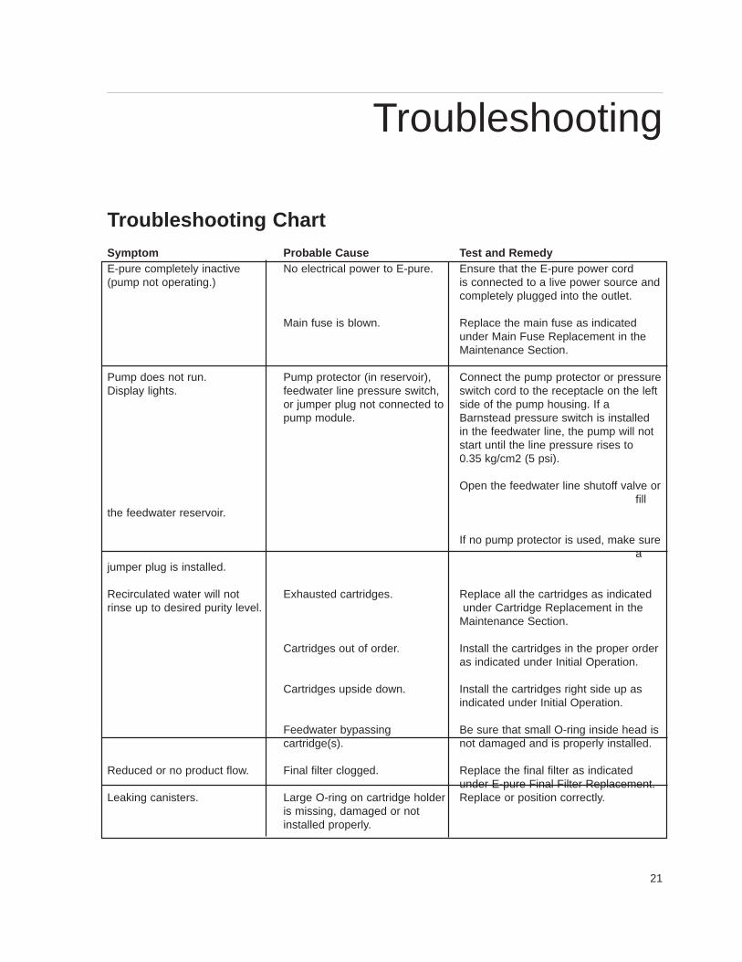
Troubleshooting ChartSymptom Probable Cause Test and RemedyE-pure completely inactive No electrical power to E-pure. Ensure that the E-pure power cord(pump not operating.) is connected to a live power source and
completely plugged into the outlet.
Main fuse is blown. Replace the main fuse as indicatedunder Main Fuse Replacement in the Maintenance Section.
Pump does not run. Pump protector (in reservoir), Connect the pump protector or pressure Display lights. feedwater line pressure switch, switch cord to the receptacle on the left
or jumper plug not connected to side of the pump housing. If a pump module. Barnstead pressure switch is installed
in the feedwater line, the pump will not start until the line pressure rises to0.35 kg/cm2 (5 psi).
Open the feedwater line shutoff valve orfill
the feedwater reservoir.
If no pump protector is used, make surea
jumper plug is installed.
Recirculated water will not Exhausted cartridges. Replace all the cartridges as indicatedrinse up to desired purity level. under Cartridge Replacement in the
Maintenance Section.
Cartridges out of order. Install the cartridges in the proper order as indicated under Initial Operation.
Cartridges upside down. Install the cartridges right side up asindicated under Initial Operation.
Feedwater bypassing Be sure that small O-ring inside head iscartridge(s). not damaged and is properly installed.
Reduced or no product flow. Final filter clogged. Replace the final filter as indicatedunder E-pure Final Filter Replacement.
Leaking canisters. Large O-ring on cartridge holder Replace or position correctly.is missing, damaged or notinstalled properly.
Troubleshooting
22
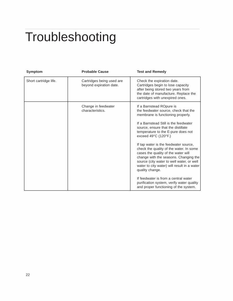
Symptom Probable Cause Test and Remedy
Short cartridge life. Cartridges being used are Check the expiration date. beyond expiration date. Cartridges begin to lose capacity
after being stored two years fromthe date of manufacture. Replace the cartridges with unexpired ones.
Change in feedwater If a Barnstead ROpure is characteristics. the feedwater source, check that the
membrane is functioning properly.
If a Barnstead Still is the feedwater source, ensure that the distillatetemperature to the E-pure does notexceed 49°C (120°F.)
If tap water is the feedwater source, check the quality of the water. In some cases the quality of the water will change with the seasons. Changing the source (city water to well water, or well water to city water) will result in a water quality change.
If feedwater is from a central waterpurification system, verify water quality and proper functioning of the system.
Troubleshooting
23
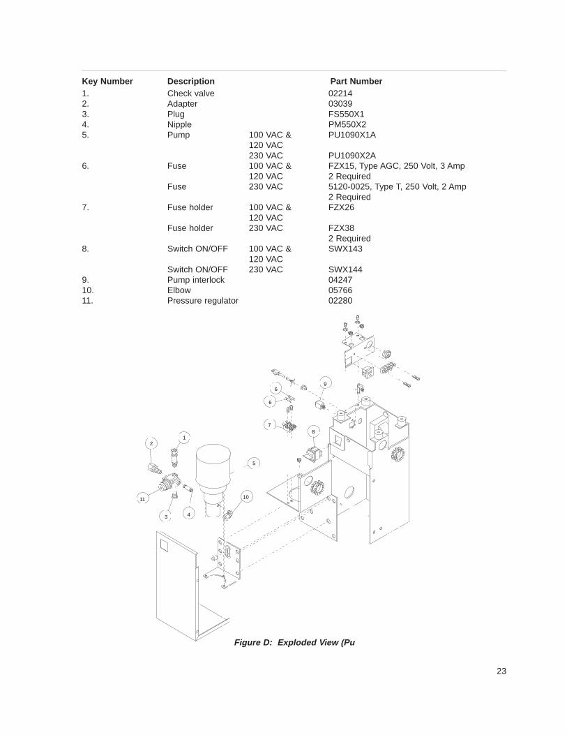
Key Number Description Part Number1. Check valve 022142. Adapter 030393. Plug FS550X14. Nipple PM550X25. Pump 100 VAC & PU1090X1A
120 VAC230 VAC PU1090X2A
6. Fuse 100 VAC & FZX15, Type AGC, 250 Volt, 3 Amp 120 VAC 2 Required
Fuse 230 VAC 5120-0025, Type T, 250 Volt, 2 Amp2 Required
7. Fuse holder 100 VAC & FZX26120 VAC
Fuse holder 230 VAC FZX382 Required
8. Switch ON/OFF 100 VAC & SWX143120 VAC
Switch ON/OFF 230 VAC SWX1449. Pump interlock 0424710. Elbow 0576611. Pressure regulator 02280
Figure D: Exploded V iew (Pu
6
6
7
9
8
10
5
43
11
21
24
Figure E: Exploded V iew (E-pure)
To E-pure
To Resistivity Meter
Normal Recirculation Pwith ultrafilter
To Ultrafilter
Recirculation fromultrafilter
Valve
To E-pure
To Resistivity Meter
Normal Recirculation Plugwith ultrafilter
Attach Recirculationline for E-Pure
Outlet and returnfrom Remote Dispenser
Valve
15
16
13
12 1110
8 7
5
14
17
1
2
3
4
69
25
Key to Figure EKey Number Description Part Number1. Cartridge handle HN550X1A2. Canister, Cartridge holder CS550X13. O-RING, large canister seal GSX284. O-RING, cartridge seal GSX275. Valve 022736. Elbow 057667. Block BK582X28. Nipple PM582X19. Adapter BR550X210. Head BK550X211. Fastener pins FP550X112. Connector (head to head) BR550X413. O-ring, head to head 0644014. Meter 100 VAC & 120 VAC D2770
Meter 230 VAC ME1090X115. Pump cabinet
120 VAC CS1090X2100 VAC CS1090X4230 VAC CS1090X3
16. Dress face -3 holder DL582X2-4 holder DL582X1A
17. Wall bracket -3 holder BC582X6A-4 holder BC582X7A
18. (not shown) Hose nipple 05930
26
Parts List
GeneralThis section contains parts list information for the E-purecartridge deionization system, Series 582. When orderingspare parts, specify part number and quantity desired.When ordering electrical parts provide voltage and frequen-cy information.
Recommended SparesConsumables . Consumable parts are those REQUIRED tosupport the day-to-day operation of this equipment.Barnstead/Thermolyne establishes two types of consum-ables; those items that MUST periodically be replaced tomaintain performance (filters, resin cartridges, etc.) andother items of limited life (fuses, etc.) that the USER canexpect to replace on a more or less random basis. Wherepractical, Barnstead/Thermolyne recommends the frequen-cy of replacement, or provides information on life expectan-cy from which the USER may calculate a replacementinterval compatible with your usage pattern.
The replacement of consumable parts is discussed in theMaintenance Section of this manual to assist the USER inaccomplishing your own service.
Consumables may be ordered separately and in some cas-es, as an Expendables Kit. Check with yourBarnstead/Thermolyne representative for additional infor-mation on the Expendables Kit.
Parts List
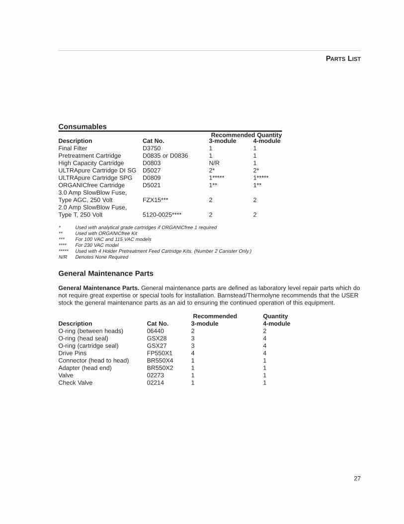
27
ConsumablesRecommended Quantity
Description Cat No. 3-module 4-moduleFinal Filter D3750 1 1Pretreatment Cartridge D0835 or D0836 1 1High Capacity Cartridge D0803 N/R 1ULTRApure Cartridge DI SG D5027 2* 2*ULTRApure Cartridge SPG D0809 1***** 1*****ORGANICfree Cartridge D5021 1** 1**3.0 Amp SlowBlow Fuse,Type AGC, 250 Volt FZX15*** 2 22.0 Amp SlowBlow Fuse,Type T, 250 Volt 5120-0025**** 2 2
* Used with analytical grade cartridges if ORGANICfree 1 required** Used with ORGANICfree Kit*** For 100 VAC and 115 VAC models**** For 230 VAC model***** Used with 4 Holder Pretreatment Feed Cartridge Kits. (Number 2 Canister Only.)N/R Denotes None Required
General Maintenance Parts
General Maintenance Parts. General maintenance parts are defined as laboratory level repair parts which donot require great expertise or special tools for installation. Barnstead/Thermolyne recommends that the USERstock the general maintenance parts as an aid to ensuring the continued operation of this equipment.
Recommended QuantityDescription Cat No. 3-module 4-moduleO-ring (between heads) 06440 2 2O-ring (head seal) GSX28 3 4O-ring (cartridge seal) GSX27 3 4Drive Pins FP550X1 4 4Connector (head to head) BR550X4 1 1Adapter (head end) BR550X2 1 1Valve 02273 1 1Check Valve 02214 1 1
PARTS LIST
28
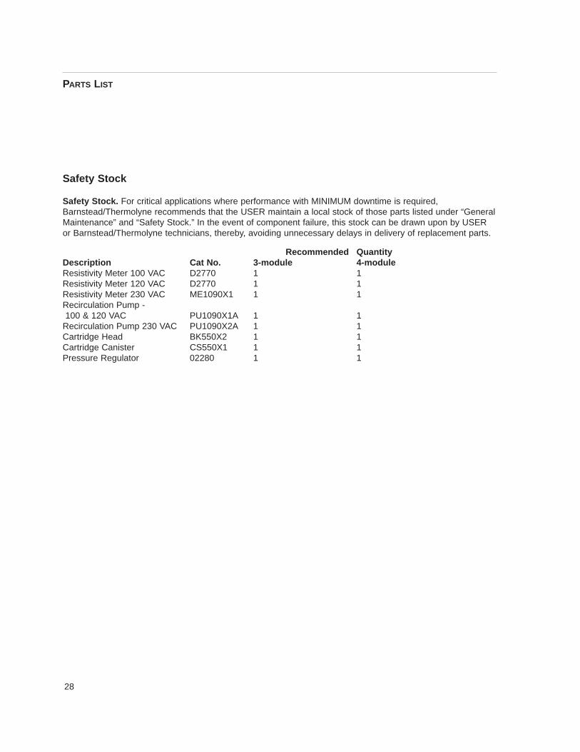
Safety Stock
Safety Stock. For critical applications where performance with MINIMUM downtime is required,Barnstead/Thermolyne recommends that the USER maintain a local stock of those parts listed under “GeneralMaintenance” and “Safety Stock.” In the event of component failure, this stock can be drawn upon by USERor Barnstead/Thermolyne technicians, thereby, avoiding unnecessary delays in delivery of replacement parts.
Recommended QuantityDescription Cat No. 3-module 4-moduleResistivity Meter 100 VAC D2770 1 1Resistivity Meter 120 VAC D2770 1 1Resistivity Meter 230 VAC ME1090X1 1 1Recirculation Pump - 100 & 120 VAC PU1090X1A 1 1
Recirculation Pump 230 VAC PU1090X2A 1 1Cartridge Head BK550X2 1 1Cartridge Canister CS550X1 1 1Pressure Regulator 02280 1 1
PARTS LIST
29
Ordering ProceduresPlease refer to the Specification Plate for the completemodel number, serial number, and series number whenrequesting service, replacement parts or in any corre-spondence concerning this unit.
All parts listed herein may be ordered from theBarnstead|Thermolyne dealer from whom you pur-chased this unit or can be obtained promptly from thefactory. When service or replacement parts are neededwe ask that you check first with your dealer. If the dealercannot handle your request, then contact our CustomerService Department at 319-556-2241 or 800-553-0039.
Prior to returning any materials toBarnstead|Thermolyne Corp ., please contact our Cus-tomer Service Department for a “Return Goods Authori-zation” number (RGA). Material returned without a RGAnumber will be refused.
shall it be liable for incidental or consequential damage.
Ordering Procedures

30

31
Barnstead|Thermolyne Corporation warrants that if a product manufactured byBarnstead|Thermolyne and sold by it within the continental United States or Canadaproves to be defective in material or construction, it will provide you, without charge, for aperiod of ninety (90) days, the labor, and a period of one (1) year, the parts, necessary toremedy any such defect. Outside the continental United States and Canada, the warrantyprovides, for one (1) year, the parts necessary to remedy any such defect. The warrantyperiod shall commence either six (6) months following the date the product is sold byBarnstead|Thermolyne or on the date it is purchased by the original retail consumer,whichever date occurs first.
All warranty inspections and repairs must be performed by and parts obtained froman authorized Barnstead|Thermolyne dealer or Barnstead|Thermolyne (at its own dis -cretion) . Heating elements, however, because of their susceptibility to overheating and con-tamination, must be returned to our factory, and if, upon inspection, it is concluded that fail-ure is not due to excessive high temperature or contamination, warranty replacement will beprovided by Barnstead|Thermolyne . The name of the authorized Barnstead|Thermolynedealer nearest you may be obtained by calling 1-800-446-6060 or writing to:
Barnstead|ThermolyneP.O. Box 797
2555 Kerper BoulevardDubuque, IA 52004-0797
USAFAX: (319) 589-0516
E-Mail: [email protected]|Thermolyne’ s sole obligation with respect to its product shall be to repair
or replace the product. Under no circumstances shall it be liable for incidental or conse-quential damage.
THE WARRANTY STATED HEREIN IS THE SOLE WARRANTY APPLICABLE TOBarnstead|Thermolyne PRODUCTS. Barnstead|Thermolyne EXPRESSLY DISCLAIMSANY AND ALL OTHER WARRANTIES, EXPRESSED OR IMPLIED, INCLUDING WAR-RANTIES OF MERCHANTABILITY OR FITNESS FOR USE.
One Year Limited Warranty

32
Barnstead Thermolyne2555 Kerper Blvd.P.O. Box 797Dubuque, IA 52004-0797 USAPHONE: 319-556-2241 • 800-553-0039FAX: 319-589-0516E-Mail: [email protected]
a subsidiary of