bas-341h instruction manual bas-342h -...
TRANSCRIPT
BAS-341H BAS-342H
Please read this manual before using the machine. Please keep this manual within easy reach for quick reference.
DIRECT DRIVE PROGRAMMABLE ELECTRONIC PATTERN SEWER
INSTRUCTION MANUALINSTRUCTION MANUAL
BAS-341H, BAS-342H
Thank you very much for buying a BROTHER sewing machine. Before using your new machine, please read the safety instructions below and the explanations given in the instruction manual.
With industrial sewing machines, it is normal to carry out work while positioned directly in front of moving parts such as the needle and thread take-up lever, and consequently there is always a danger of injury that can be caused by these parts. Follow the instructions from training personnel and instructors regarding safe and correct operation before operating the machine so that you will know how to use it correctly.
iBAS-341H, BAS-342H
SAFETY INSTRUCTIONS
[1] Safety indications and their meanings This instruction manual and the indications and symbols that are used on the machine itself are provided in order to ensure safe operation of this machine and to prevent accidents and injury to yourself or other people. The meanings of these indications and symbols are given below.
Indications
DANGER The instructions which follow this term indicate situations where failure to follow the instructions will result in death or serious injury.
WARNING The instructions which follow this term indicate situations where failure to follow the instructions could result in death or serious injury.
CAUTION The instructions which follow this term indicate situations where failure to follow the instructions may result in minor or moderate injury.
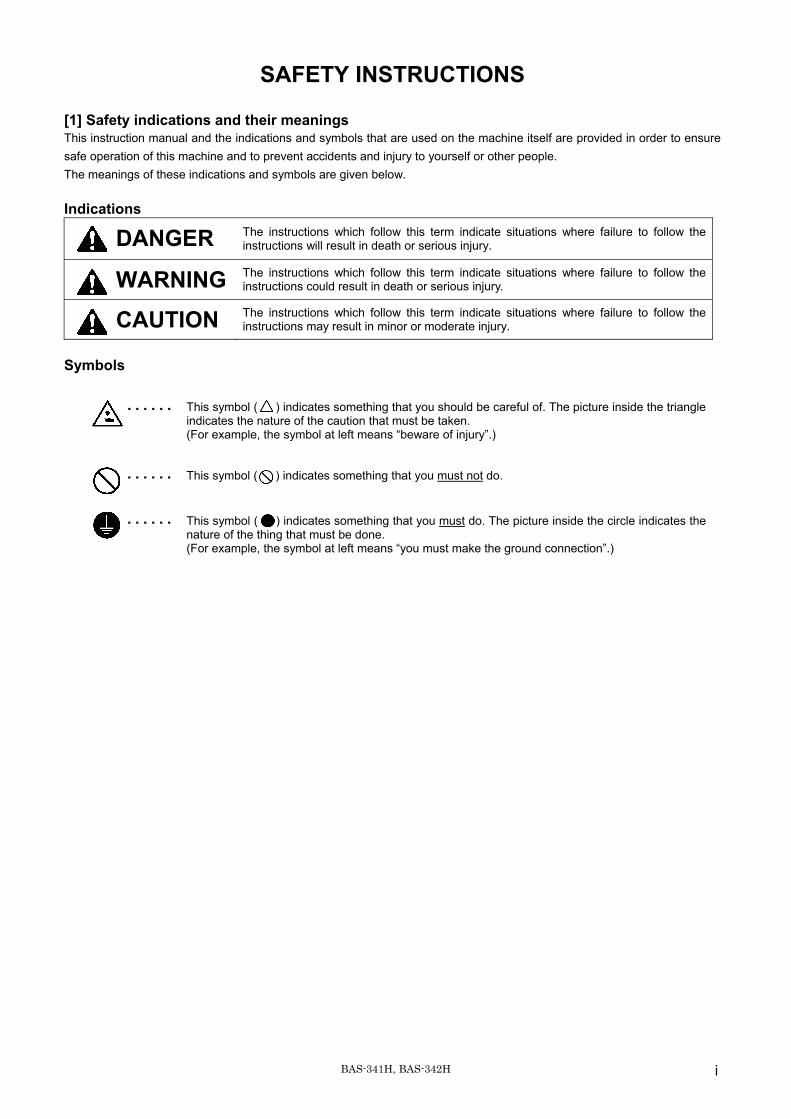
Symbols
・・・・・・ This symbol ( ) indicates something that you should be careful of. The picture inside the triangle indicates the nature of the caution that must be taken. (For example, the symbol at left means “beware of injury”.)
・・・・・・ This symbol ( ) indicates something that you must not do.
・・・・・・ This symbol ( ) indicates something that you must do. The picture inside the circle indicates the nature of the thing that must be done. (For example, the symbol at left means “you must make the ground connection”.)
ii BAS-341H, BAS-342H
[2] Notes on safety
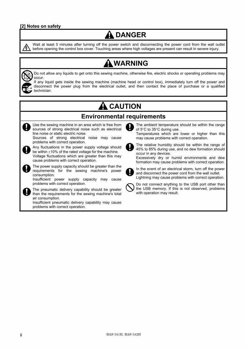
DANGER Wait at least 5 minutes after turning off the power switch and disconnecting the power cord from the wall outlet before opening the control box cover. Touching areas where high voltages are present can result in severe injury.
WARNING Do not allow any liquids to get onto this sewing machine, otherwise fire, electric shocks or operating problems may occur. If any liquid gets inside the sewing machine (machine head or control box), immediately turn off the power and disconnect the power plug from the electrical outlet, and then contact the place of purchase or a qualified technician.
CAUTION Environmental requirements
Use the sewing machine in an area which is free from sources of strong electrical noise such as electrical line noise or static electric noise. Sources of strong electrical noise may cause problems with correct operation. Any fluctuations in the power supply voltage should be within ±10% of the rated voltage for the machine. Voltage fluctuations which are greater than this may cause problems with correct operation. The power supply capacity should be greater than the requirements for the sewing machine's power consumption. Insufficient power supply capacity may cause problems with correct operation. The pneumatic delivery capability should be greater than the requirements for the sewing machine's total air consumption. Insufficient pneumatic delivery capability may cause problems with correct operation.
The ambient temperature should be within the range of 5°C to 35°C during use. Temperatures which are lower or higher than this may cause problems with correct operation.
The relative humidity should be within the range of 45% to 85% during use, and no dew formation should occur in any devices. Excessively dry or humid environments and dew formation may cause problems with correct operation.
In the event of an electrical storm, turn off the power and disconnect the power cord from the wall outlet. Lightning may cause problems with correct operation.
Do not connect anything to the USB port other than the USB memory. If this is not observed, problems with operation may result.
iiiBAS-341H, BAS-342H
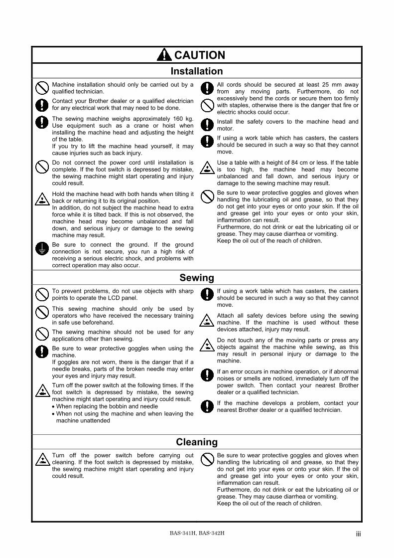
CAUTION Installation
Machine installation should only be carried out by a qualified technician. Contact your Brother dealer or a qualified electrician for any electrical work that may need to be done.
The sewing machine weighs approximately 160 kg. Use equipment such as a crane or hoist when installing the machine head and adjusting the height of the table. If you try to lift the machine head yourself, it may cause injuries such as back injury. Do not connect the power cord until installation is complete. If the foot switch is depressed by mistake, the sewing machine might start operating and injury could result.
Hold the machine head with both hands when tilting it back or returning it to its original position. In addition, do not subject the machine head to extra force while it is tilted back. If this is not observed, the machine head may become unbalanced and fall down, and serious injury or damage to the sewing machine may result. Be sure to connect the ground. If the ground connection is not secure, you run a high risk of receiving a serious electric shock, and problems with correct operation may also occur.
All cords should be secured at least 25 mm away from any moving parts. Furthermore, do not excessively bend the cords or secure them too firmly with staples, otherwise there is the danger that fire or electric shocks could occur. Install the safety covers to the machine head and motor. If using a work table which has casters, the casters should be secured in such a way so that they cannot move.
Use a table with a height of 84 cm or less. If the table is too high, the machine head may become unbalanced and fall down, and serious injury or damage to the sewing machine may result. Be sure to wear protective goggles and gloves when handling the lubricating oil and grease, so that they do not get into your eyes or onto your skin. If the oil and grease get into your eyes or onto your skin, inflammation can result. Furthermore, do not drink or eat the lubricating oil or grease. They may cause diarrhea or vomiting. Keep the oil out of the reach of children.
Sewing To prevent problems, do not use objects with sharp points to operate the LCD panel.
This sewing machine should only be used by operators who have received the necessary training in safe use beforehand. The sewing machine should not be used for any applications other than sewing. Be sure to wear protective goggles when using the machine. If goggles are not worn, there is the danger that if a needle breaks, parts of the broken needle may enter your eyes and injury may result. Turn off the power switch at the following times. If the foot switch is depressed by mistake, the sewing machine might start operating and injury could result.• When replacing the bobbin and needle • When not using the machine and when leaving the
machine unattended
If using a work table which has casters, the casters should be secured in such a way so that they cannot move.
Attach all safety devices before using the sewing machine. If the machine is used without these devices attached, injury may result.
Do not touch any of the moving parts or press any objects against the machine while sewing, as this may result in personal injury or damage to the machine.
If an error occurs in machine operation, or if abnormal noises or smells are noticed, immediately turn off the power switch. Then contact your nearest Brother dealer or a qualified technician.
If the machine develops a problem, contact your nearest Brother dealer or a qualified technician.
Cleaning Turn off the power switch before carrying out cleaning. If the foot switch is depressed by mistake, the sewing machine might start operating and injury could result.
Be sure to wear protective goggles and gloves when handling the lubricating oil and grease, so that they do not get into your eyes or onto your skin. If the oil and grease get into your eyes or onto your skin, inflammation can result. Furthermore, do not drink or eat the lubricating oil or grease. They may cause diarrhea or vomiting. Keep the oil out of the reach of children.
iv BAS-341H, BAS-342H
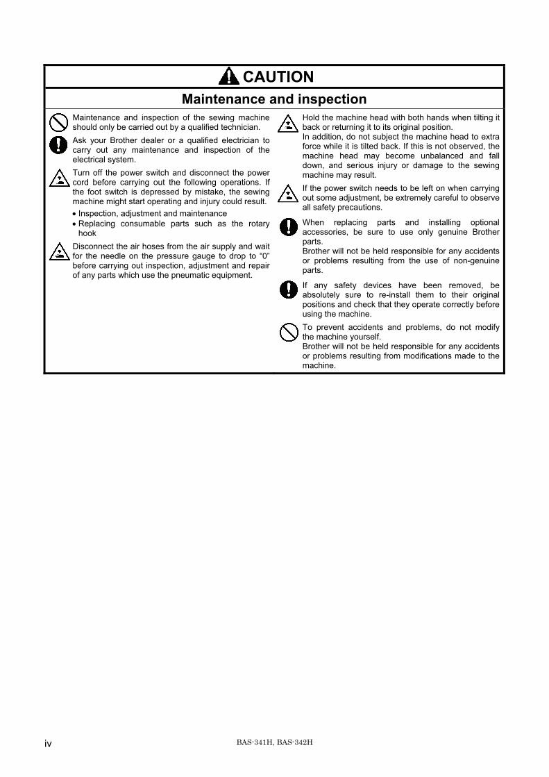
CAUTION Maintenance and inspection
Maintenance and inspection of the sewing machine should only be carried out by a qualified technician. Ask your Brother dealer or a qualified electrician to carry out any maintenance and inspection of the electrical system. Turn off the power switch and disconnect the power cord before carrying out the following operations. If the foot switch is depressed by mistake, the sewing machine might start operating and injury could result.• Inspection, adjustment and maintenance • Replacing consumable parts such as the rotary
hook Disconnect the air hoses from the air supply and wait for the needle on the pressure gauge to drop to “0” before carrying out inspection, adjustment and repair of any parts which use the pneumatic equipment.
Hold the machine head with both hands when tilting it back or returning it to its original position. In addition, do not subject the machine head to extra force while it is tilted back. If this is not observed, the machine head may become unbalanced and fall down, and serious injury or damage to the sewing machine may result. If the power switch needs to be left on when carrying out some adjustment, be extremely careful to observe all safety precautions.
When replacing parts and installing optional accessories, be sure to use only genuine Brother parts. Brother will not be held responsible for any accidents or problems resulting from the use of non-genuine parts.
If any safety devices have been removed, be absolutely sure to re-install them to their original positions and check that they operate correctly before using the machine. To prevent accidents and problems, do not modify the machine yourself. Brother will not be held responsible for any accidents or problems resulting from modifications made to the machine.
vBAS-341H, BAS-342H
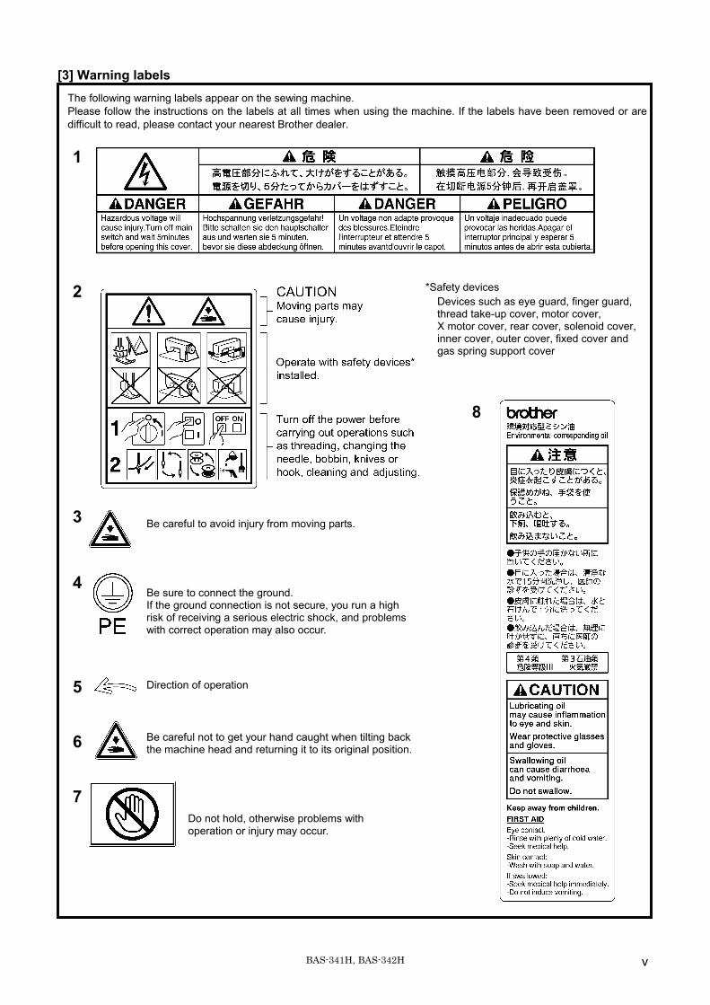
[3] Warning labels
The following warning labels appear on the sewing machine. Please follow the instructions on the labels at all times when using the machine. If the labels have been removed or are difficult to read, please contact your nearest Brother dealer. 1
2
.
3 4 5 6 7
Be careful to avoid injury from moving parts. Be sure to connect the ground. If the ground connection is not secure, you run a high risk of receiving a serious electric shock, and problems with correct operation may also occur.
Direction of operation
Be careful not to get your hand caught when tilting back the machine head and returning it to its original position.
Do not hold, otherwise problems with operation or injury may occur.
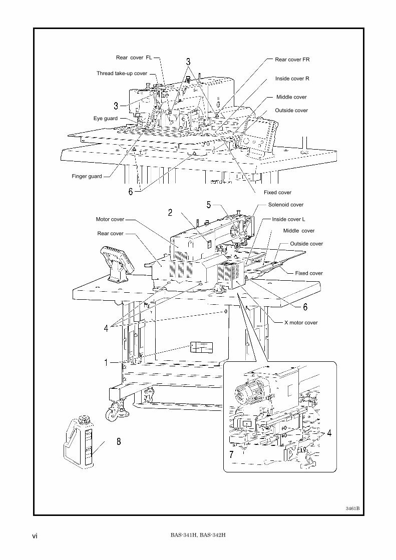
*Safety devices Devices such as eye guard, finger guard, thread take-up cover, motor cover, X motor cover, rear cover, solenoid cover, inner cover, outer cover, fixed cover and gas spring support cover
8
vi BAS-341H, BAS-342H
Solenoid cover
Rear cover
Inside cover L
Outside cover
Fixed cover
X motor cover
Motor cover
3461B
Middle cover
Thread take-up cover
Eye guard
Finger guard
Rear cover FL Rear cover FR
Fixed cover
Inside cover R
Middle cover
Outside cover
BAS-341H, BAS-342H
CONTENTS
1. NAMES OF MAJOR PARTS ................ 1 2. SPECIFICATIONS ................................ 2 3. INSTALLATION.................................... 3 3-1. Table processing diagram ................................ 4 3-2. Installing the control box................................... 5 3-3. Installing the oil pan and support lever base.... 6 3-4. Installing the machine head.............................. 6 3-5. Tilting back and returning the machine head ... 7 3-6. Installing the gas spring .................................. 8 3-7. Installing the LCD panel ................................... 9 3-8. Installing the solenoid valve assembly ............. 10 3-9. Connecting the air tubes................................... 10 3-10. Installing the air hose...................................... 10 3-11. Installing the two-pedal foot switch................. 11 3-12. Installing the cords.......................................... 11 3-13. Connecting the ground wire............................ 15 3-14. Securing the cords and air tubes.................... 16 3-15. Connecting the power cord............................. 17 3-16. Installing the eye guard .................................. 20 3-17. Installing the cotton stand............................... 20 3-18. Lubrication ...................................................... 21 3-19. Checking the machine head switch................ 22
4. PREPARATION BEFORE SEWING.....23 4-1. Installing the needle.......................................... 23 4-2. 2-pedal foot switch operation method .............. 23 4-3. Threading the upper thread.............................. 24 4-4. Winding the lower thread.................................. 26 4-5. Installing the bobbin case................................. 27 4-6. Thread tension.................................................. 28
4-6-1. Lower thread tension .............................. 28 4-6-2. Upper thread tension .............................. 29
4-7. Starting up ........................................................ 30 4-8. Setting 2-step operation for the work clamp..... 31
5. SEWING................................................32 5-1. Sewing .............................................................. 32 5-2. Using the STOP switch..................................... 33
6. CLEANING ...........................................34 6-1. Cleaning the rotary hook .................................. 34 6-2. Draining the oil.................................................. 34 6-3. Cleaning the regulator ...................................... 35 6-4. Checking the control box air inlet ports ............ 35 6-5. Cleaning the eye guard ................................... 35 6-6. Checking the needle ....................................... 35 6-7. Lubrication ........................................................ 35
7.STANDARD ADJUSTMENTS................36 7-1. Adjusting the sensitivity of the thread breakage
sensor ...............................................................36 7-2. Thread take-up spring.......................................37 7-3. Arm thread guide R...........................................37 7-4. Adjusting the needle bar height ........................38 7-5. Adjusting the needle and rotary hook timing.....38 7-6. Adjusting the driver (needle guard) position .....39 7-7. Adjusting the clearance between the
needle and rotary hook tip ................................39 7-8. Adjusting the shuttle race thread guide ............39 7-9. Rotary hook lubrication amount ........................40 7-10. Adjusting the position of the movable knife ....41 7-11. Replacing the movable and fixed knives ........43 7-12. Installing the feed plate ...................................44 7-13. Adjusting the thread wiper ..............................44 7-14. Intermittent presser foot installation position ..45 7-15. Adjusting the intermittent presser foot ............45 7-16. Adjusting the work clamp lift amount ..............47 7-17. Adjusting the air pressure ...............................47 7-18. Adjusting the speed controller.........................48 7-19. If processing the work clamps and the
feed plate to a shape that matches the sewing pattern ................................................49
8. LIST OF ERROR CODES.....................51 9. TROUBLESHOOTING..........................57
1. NAMES OF MAJOR PARTS
BAS-341H, BAS-342H1
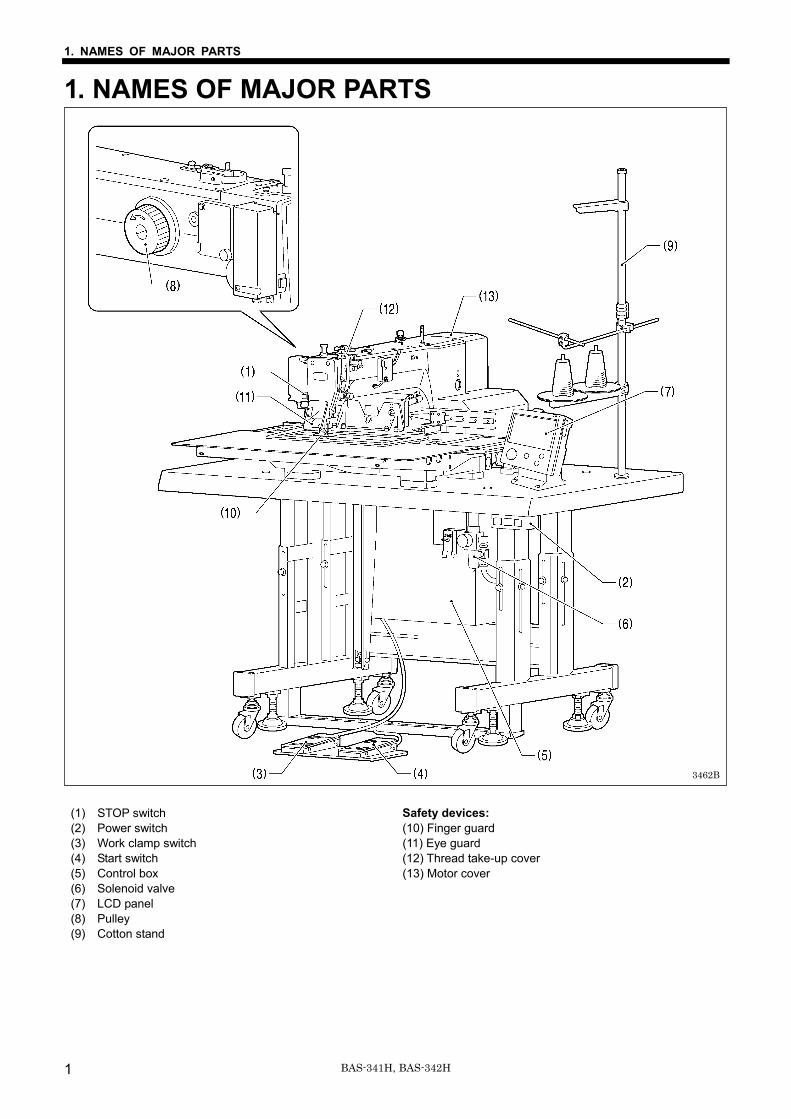
1. NAMES OF MAJOR PARTS (1) STOP switch Safety devices: (2) Power switch (10) Finger guard (3) Work clamp switch (11) Eye guard (4) Start switch (12) Thread take-up cover (5) Control box (13) Motor cover (6) Solenoid valve (7) LCD panel (8) Pulley (9) Cotton stand
3462B
2. SPECIFICATIONS
BAS-341H, BAS-342H 2
2. SPECIFICATIONS
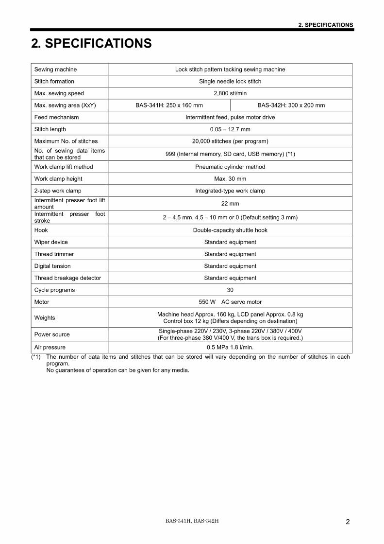
Sewing machine Lock stitch pattern tacking sewing machine
Stitch formation Single needle lock stitch
Max. sewing speed 2,800 sti/min
Max. sewing area (XxY) BAS-341H: 250 x 160 mm BAS-342H: 300 x 200 mm
Feed mechanism Intermittent feed, pulse motor drive
Stitch length 0.05 − 12.7 mm
Maximum No. of stitches 20,000 stitches (per program) No. of sewing data items that can be stored 999 (Internal memory, SD card, USB memory) (*1)
Work clamp lift method Pneumatic cylinder method
Work clamp height Max. 30 mm
2-step work clamp Integrated-type work clamp Intermittent presser foot lift amount 22 mm
Intermittent presser foot stroke 2 − 4.5 mm, 4.5 − 10 mm or 0 (Default setting 3 mm)
Hook Double-capacity shuttle hook
Wiper device Standard equipment
Thread trimmer Standard equipment
Digital tension Standard equipment
Thread breakage detector Standard equipment
Cycle programs 30
Motor 550 W AC servo motor
Weights Machine head Approx. 160 kg, LCD panel Approx. 0.8 kg Control box 12 kg (Differs depending on destination)
Power source Single-phase 220V / 230V, 3-phase 220V / 380V / 400V (For three-phase 380 V/400 V, the trans box is required.)
Air pressure 0.5 MPa 1.8 l/min. (*1) The number of data items and stitches that can be stored will vary depending on the number of stitches in each
program. No guarantees of operation can be given for any media.
3. INSTALLATION
3 BAS-341H, BAS-342H
3. INSTALLATION CAUTION
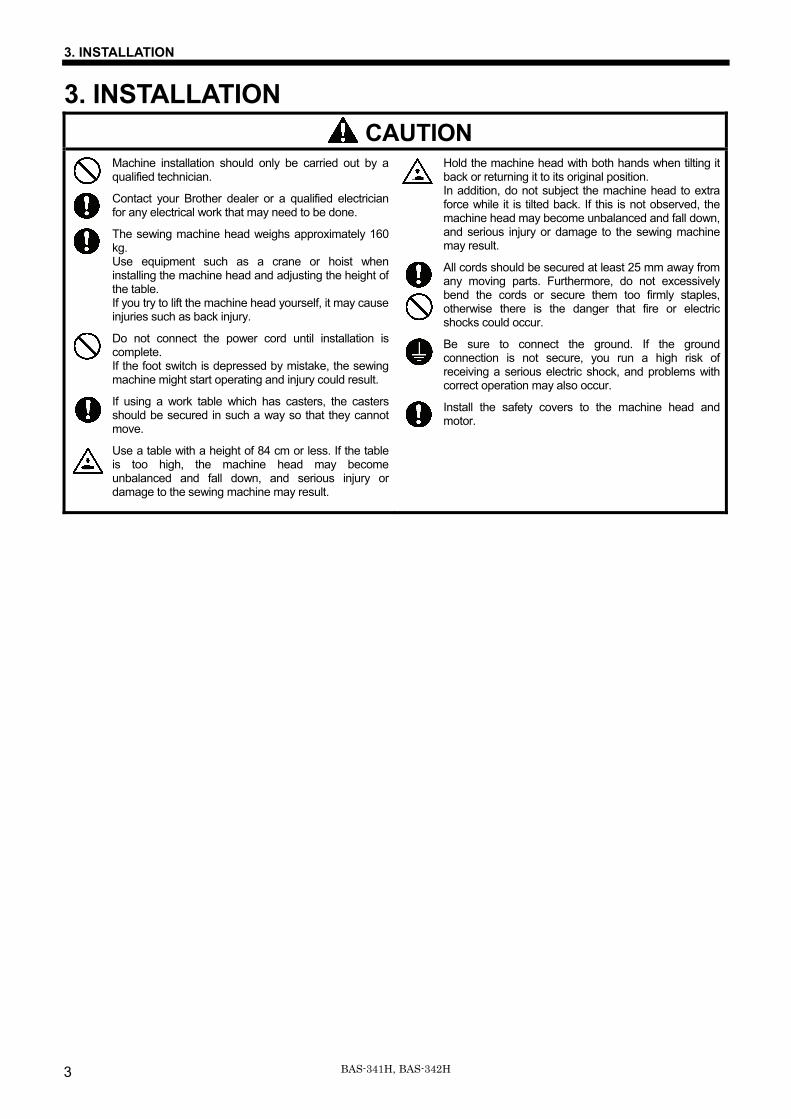
Machine installation should only be carried out by a qualified technician.
Contact your Brother dealer or a qualified electrician for any electrical work that may need to be done.
The sewing machine head weighs approximately 160 kg. Use equipment such as a crane or hoist when installing the machine head and adjusting the height of the table. If you try to lift the machine head yourself, it may cause injuries such as back injury.
Do not connect the power cord until installation is complete. If the foot switch is depressed by mistake, the sewing machine might start operating and injury could result.
If using a work table which has casters, the casters should be secured in such a way so that they cannot move.
Use a table with a height of 84 cm or less. If the table is too high, the machine head may become unbalanced and fall down, and serious injury or damage to the sewing machine may result.
Hold the machine head with both hands when tilting it back or returning it to its original position. In addition, do not subject the machine head to extra force while it is tilted back. If this is not observed, the machine head may become unbalanced and fall down, and serious injury or damage to the sewing machine may result.
All cords should be secured at least 25 mm away from any moving parts. Furthermore, do not excessively bend the cords or secure them too firmly staples, otherwise there is the danger that fire or electric shocks could occur.
Be sure to connect the ground. If the ground connection is not secure, you run a high risk of receiving a serious electric shock, and problems with correct operation may also occur.
Install the safety covers to the machine head and motor.
3. INSTALLATION
4BAS-341H, BAS-342H
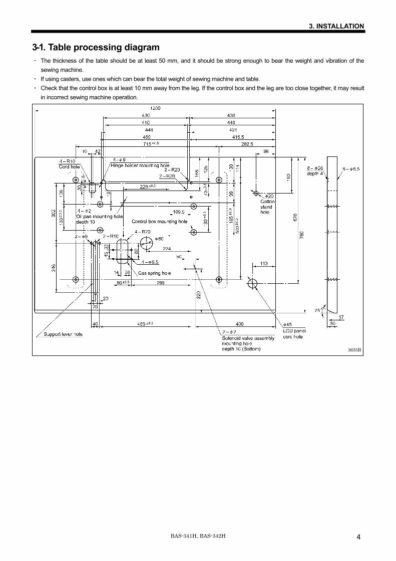
3-1. Table processing diagram ・ The thickness of the table should be at least 50 mm, and it should be strong enough to bear the weight and vibration of the
sewing machine. ・ If using casters, use ones which can bear the total weight of sewing machine and table. ・ Check that the control box is at least 10 mm away from the leg. If the control box and the leg are too close together, it may result
in incorrect sewing machine operation.
3635B
3. INSTALLATION
5 BAS-341H, BAS-342H
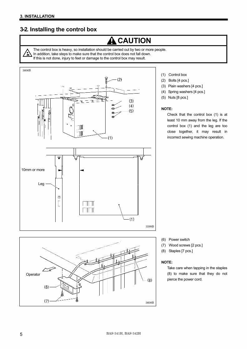
3-2. Installing the control box
CAUTION The control box is heavy, so installation should be carried out by two or more people. In addition, take steps to make sure that the control box does not fall down. If this is not done, injury to feet or damage to the control box may result.
(1) Control box (2) Bolts [4 pcs.] (3) Plain washers [4 pcs.] (4) Spring washers [4 pcs.] (5) Nuts [8 pcs.] NOTE: Check that the control box (1) is at
least 10 mm away from the leg. If the control box (1) and the leg are too close together, it may result in incorrect sewing machine operation.
(6) Power switch (7) Wood screws [2 pcs.] (8) Staples [7 pcs.] NOTE:
Take care when tapping in the staples (8) to make sure that they do not pierce the power cord.
Operator
3608B
3606B
3599B
10mm or more
Leg
3. INSTALLATION
6BAS-341H, BAS-342H
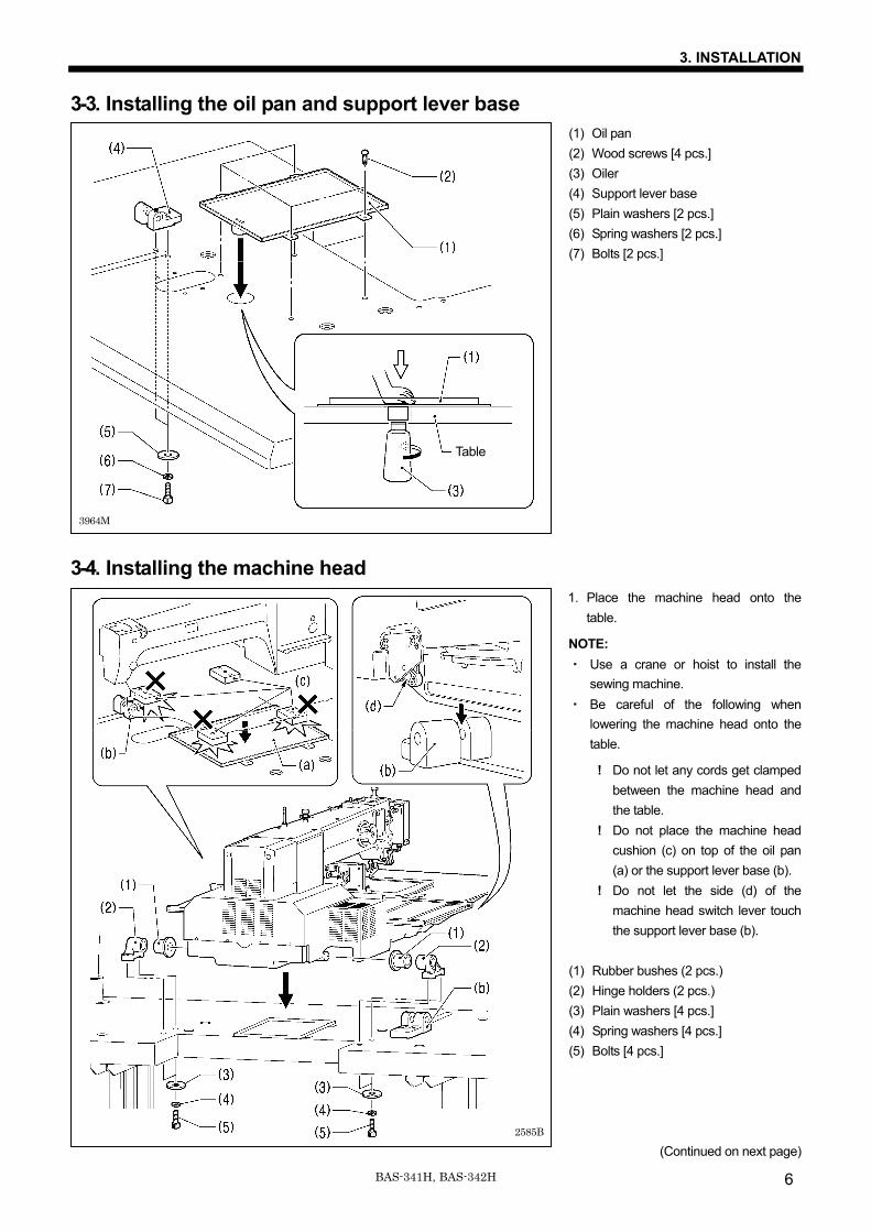
3-3. Installing the oil pan and support lever base (1) Oil pan (2) Wood screws [4 pcs.] (3) Oiler (4) Support lever base (5) Plain washers [2 pcs.] (6) Spring washers [2 pcs.] (7) Bolts [2 pcs.]
3-4. Installing the machine head 1. Place the machine head onto the
table.
NOTE: ・ Use a crane or hoist to install the
sewing machine. ・ Be careful of the following when
lowering the machine head onto the table.
! Do not let any cords get clamped between the machine head and the table.
! Do not place the machine head cushion (c) on top of the oil pan (a) or the support lever base (b).
! Do not let the side (d) of the machine head switch lever touch the support lever base (b).
(1) Rubber bushes (2 pcs.) (2) Hinge holders (2 pcs.) (3) Plain washers [4 pcs.] (4) Spring washers [4 pcs.] (5) Bolts [4 pcs.]
(Continued on next page) 2585B
3964M
Table
3. INSTALLATION
7 BAS-341H, BAS-342H
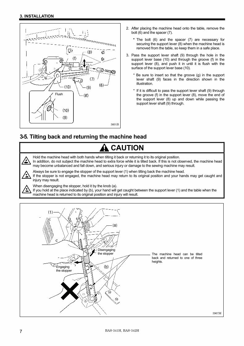
2. After placing the machine head onto the table, remove the bolt (6) and the spacer (7).
* The bolt (6) and the spacer (7) are necessary for securing the support lever (8) when the machine head is removed from the table, so keep them in a safe place.
3. Pass the support lever shaft (9) through the hole in the support lever base (10) and through the groove (f) in the support lever (8), and push it in until it is flush with the surface of the support lever base (10).
* Be sure to insert so that the groove (g) in the support lever shaft (9) faces in the direction shown in the illustration.
* If it is difficult to pass the support lever shaft (9) through the groove (f) in the support lever (8), move the end of the support lever (8) up and down while passing the support lever shaft (9) through.
3-5. Tilting back and returning the machine head
CAUTION Hold the machine head with both hands when tilting it back or returning it to its original position. In addition, do not subject the machine head to extra force while it is tilted back. If this is not observed, the machine head may become unbalanced and fall down, and serious injury or damage to the sewing machine may result. Always be sure to engage the stopper of the support lever (1) when tilting back the machine head. If the stopper is not engaged, the machine head may return to its original position and your hands may get caught and injury may result. When disengaging the stopper, hold it by the knob (a). If you hold at the place indicated by (b), your hand will get caught between the support lever (1) and the table when the machine head is returned to its original position and injury will result.
3967M
3601B
Flush
The machine head can be tilted back and returned to one of three heights.
Engaging the stopper
Disengaging the stopper
3. INSTALLATION
8BAS-341H, BAS-342H
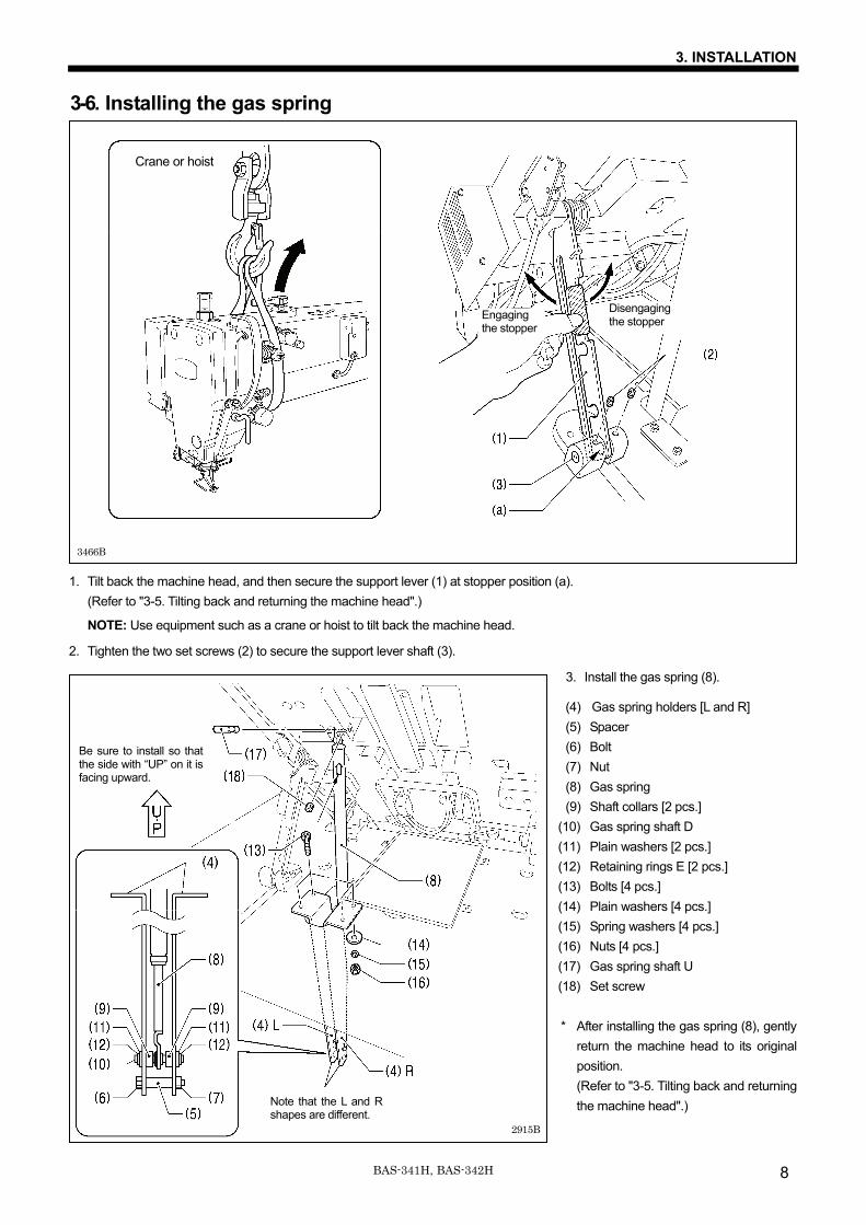
3-6. Installing the gas spring
1. Tilt back the machine head, and then secure the support lever (1) at stopper position (a). (Refer to "3-5. Tilting back and returning the machine head".)
NOTE: Use equipment such as a crane or hoist to tilt back the machine head.
2. Tighten the two set screws (2) to secure the support lever shaft (3).
3. Install the gas spring (8).
(4) Gas spring holders [L and R] (5) Spacer (6) Bolt (7) Nut (8) Gas spring (9) Shaft collars [2 pcs.]
(10) Gas spring shaft D (11) Plain washers [2 pcs.] (12) Retaining rings E [2 pcs.] (13) Bolts [4 pcs.] (14) Plain washers [4 pcs.] (15) Spring washers [4 pcs.] (16) Nuts [4 pcs.] (17) Gas spring shaft U (18) Set screw
* After installing the gas spring (8), gently
return the machine head to its original position. (Refer to "3-5. Tilting back and returning the machine head".)
Engaging the stopper
Disengaging the stopper
3466B
Crane or hoist
2915B
Note that the L and R shapes are different.
Be sure to install so that the side with “UP” on it is facing upward.
3. INSTALLATION
9 BAS-341H, BAS-342H
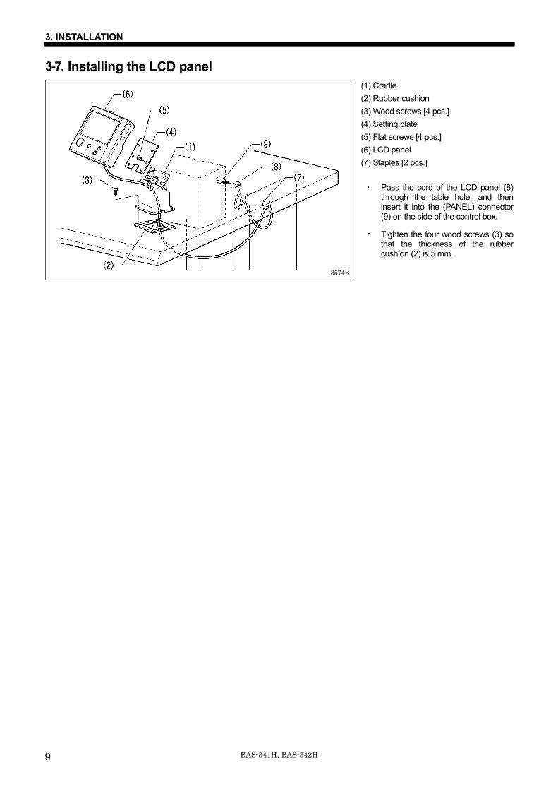
3-7. Installing the LCD panel (1) Cradle (2) Rubber cushion (3) Wood screws [4 pcs.] (4) Setting plate (5) Flat screws [4 pcs.] (6) LCD panel (7) Staples [2 pcs.]
・ Pass the cord of the LCD panel (8)
through the table hole, and then insert it into the (PANEL) connector (9) on the side of the control box.
・ Tighten the four wood screws (3) so that the thickness of the rubber cushion (2) is 5 mm.
3574B
3. INSTALLATION
10BAS-341H, BAS-342H
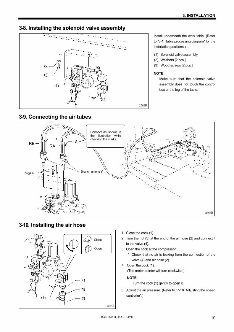
3-8. Installing the solenoid valve assembly Install underneath the work table. (Refer to "3-1. Table processing diagram" for the installation positions.)
(1) Solenoid valve assembly (2) Washers [2 pcs.] (3) Wood screws [2 pcs.]
NOTE: Make sure that the solenoid valve assembly does not touch the control box or the leg of the table.
3-9. Connecting the air tubes
3-10. Installing the air hose 1. Close the cock (1). 2. Turn the nut (3) at the end of the air hose (2) and connect it
to the valve (4). 3. Open the cock at the compressor.
* Check that no air is leaking from the connection of the valve (4) and air hose (2).
4. Open the cock (1). (The meter pointer will turn clockwise.)
NOTE: Turn the cock (1) gently to open it.
5. Adjust the air pressure. (Refer to "7-18. Adjusting the speed controller".)
2562B
Close
Open
2564B
Connect as shown in the illustration while checking the marks.
Plugs 4 Branch unions Y
2563B
3. INSTALLATION
11 BAS-341H, BAS-342H
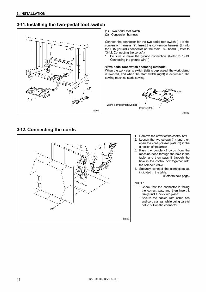
3-11. Installing the two-pedal foot switch (1) Two-pedal foot switch (2) Conversion harness Connect the connector for the two-pedal foot switch (1) to the conversion harness (2). Insert the conversion harness (2) into the P15 (PEDAL) connector on the main P.C. board. (Refer to "3-12. Connecting the cords".) * Be sure to make the ground connection. (Refer to “3-13.
Connecting the ground wire”.) <Two-pedal foot switch operating method> When the work clamp switch (left) is depressed, the work clamp is lowered, and when the start switch (right) is depressed, the sewing machine starts sewing.
3-12. Connecting the cords 1. Remove the cover of the control box. 2. Loosen the two screws (1), and then
open the cord presser plate (2) in the direction of the arrow.
3. Pass the bundle of cords from the machine head through the hole in the table, and then pass it through the hole in the control box together with the solenoid valve.
4. Securely connect the connectors as indicated in the table.
(Refer to next page) NOTE:
・ Check that the connector is facing the correct way, and then insert it firmly until it locks into place.
・ Secure the cables with cable ties and cord clamps, while being careful not to pull on the connector.
4923Q
Start switch Work clamp switch (2-step)
3530B
3568B
3. INSTALLATION
12BAS-341H, BAS-342H
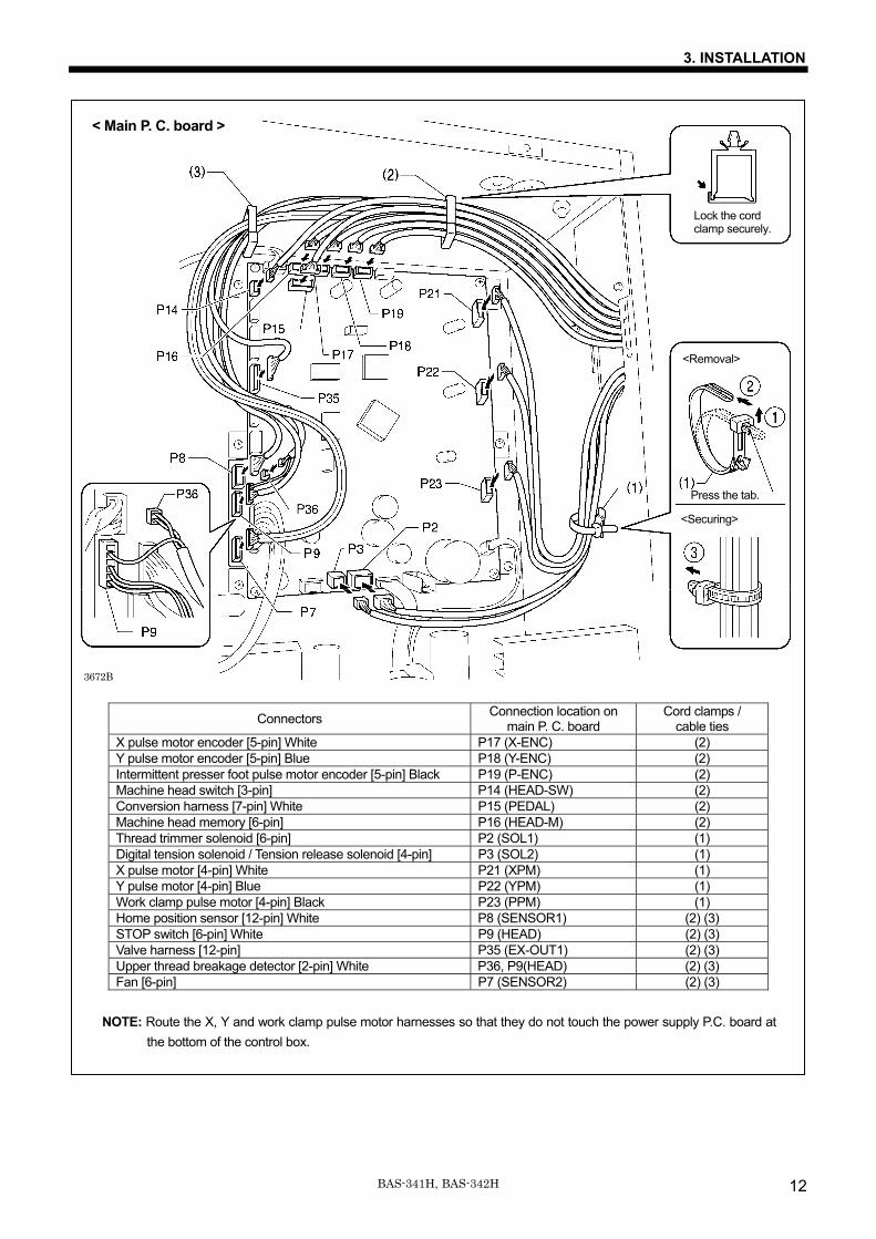
NOTE: Route the X, Y and work clamp pulse motor harnesses so that they do not touch the power supply P.C. board at the bottom of the control box.
Connectors Connection location on main P. C. board
Cord clamps / cable ties
X pulse motor encoder [5-pin] White P17 (X-ENC) (2) Y pulse motor encoder [5-pin] Blue P18 (Y-ENC) (2) Intermittent presser foot pulse motor encoder [5-pin] Black P19 (P-ENC) (2) Machine head switch [3-pin] P14 (HEAD-SW) (2) Conversion harness [7-pin] White P15 (PEDAL) (2) Machine head memory [6-pin] P16 (HEAD-M) (2) Thread trimmer solenoid [6-pin] P2 (SOL1) (1) Digital tension solenoid / Tension release solenoid [4-pin] P3 (SOL2) (1) X pulse motor [4-pin] White P21 (XPM) (1) Y pulse motor [4-pin] Blue P22 (YPM) (1) Work clamp pulse motor [4-pin] Black P23 (PPM) (1) Home position sensor [12-pin] White P8 (SENSOR1) (2) (3) STOP switch [6-pin] White P9 (HEAD) (2) (3) Valve harness [12-pin] P35 (EX-OUT1) (2) (3) Upper thread breakage detector [2-pin] White P36, P9(HEAD) (2) (3) Fan [6-pin] P7 (SENSOR2) (2) (3)
3672B
Lock the cord clamp securely.
<Removal>
Press the tab.
<Securing>
< Main P. C. board >
3. INSTALLATION
13 BAS-341H, BAS-342H
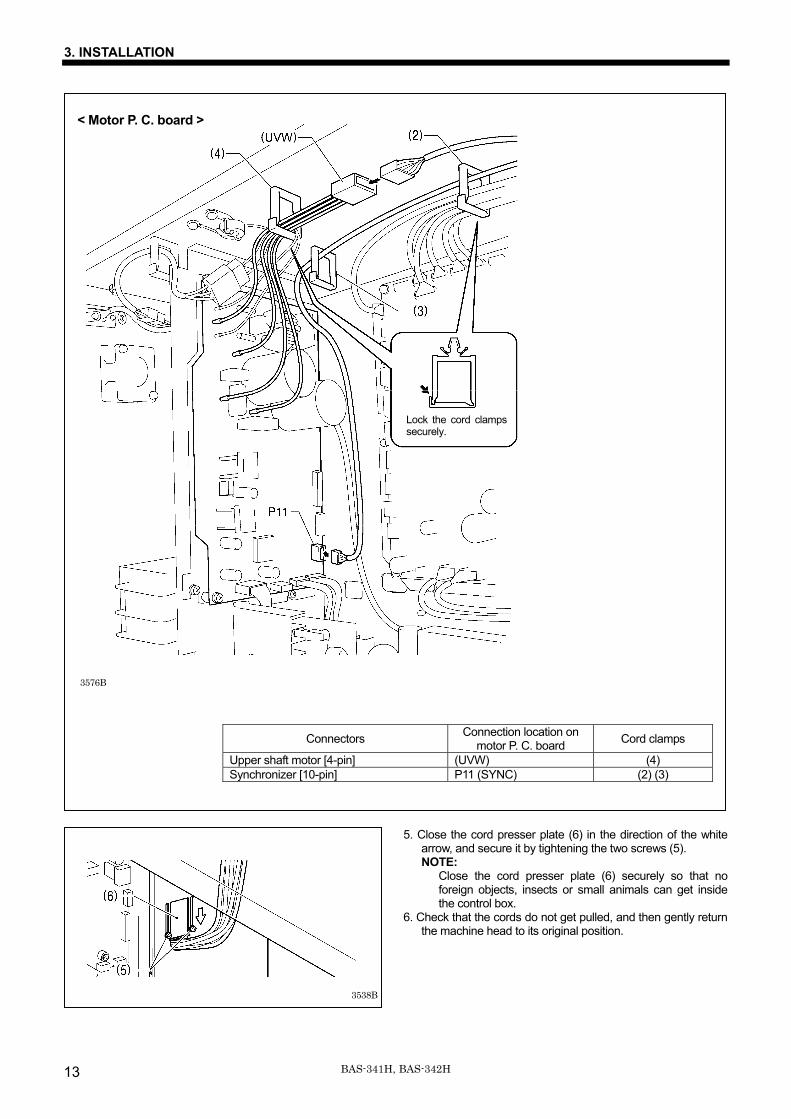
Connectors Connection location on motor P. C. board Cord clamps
Upper shaft motor [4-pin] (UVW) (4) Synchronizer [10-pin] P11 (SYNC) (2) (3)
5. Close the cord presser plate (6) in the direction of the white arrow, and secure it by tightening the two screws (5). NOTE:
Close the cord presser plate (6) securely so that no foreign objects, insects or small animals can get inside the control box.
6. Check that the cords do not get pulled, and then gently return the machine head to its original position.
3538B
< Motor P. C. board >
Lock the cord clamps securely.
3576B
3. INSTALLATION
14BAS-341H, BAS-342H
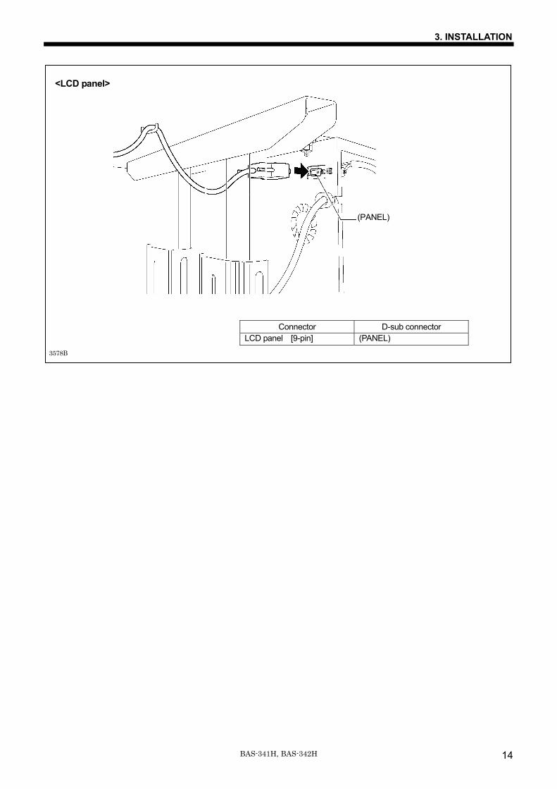
Connector D-sub connector LCD panel [9-pin] (PANEL)
<LCD panel>
3578B
(PANEL)
3. INSTALLATION
15 BAS-341H, BAS-342H
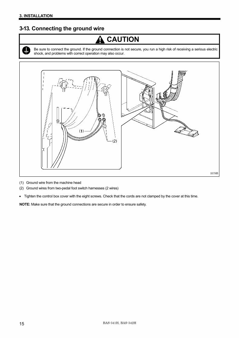
3-13. Connecting the ground wire
CAUTION Be sure to connect the ground. If the ground connection is not secure, you run a high risk of receiving a serious electric shock, and problems with correct operation may also occur.
(1) Ground wire from the machine head (2) Ground wires from two-pedal foot switch harnesses (2 wires)
• Tighten the control box cover with the eight screws. Check that the cords are not clamped by the cover at this time.
NOTE: Make sure that the ground connections are secure in order to ensure safety.
3579B
3. INSTALLATION
16BAS-341H, BAS-342H
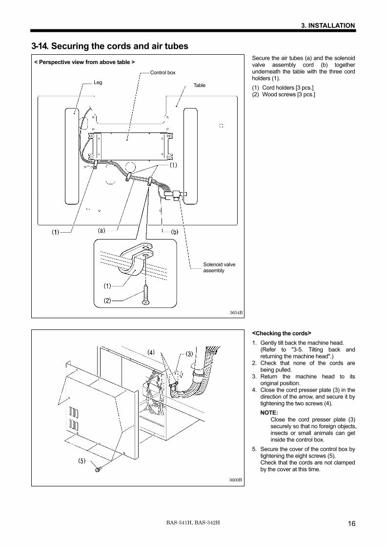
3-14. Securing the cords and air tubes Secure the air tubes (a) and the solenoid valve assembly cord (b) together underneath the table with the three cord holders (1). (1) Cord holders [3 pcs.] (2) Wood screws [3 pcs.] <Checking the cords> 1. Gently tilt back the machine head.
(Refer to "3-5. Tilting back and returning the machine head".)
2. Check that none of the cords are being pulled.
3. Return the machine head to its original position.
4. Close the cord presser plate (3) in the direction of the arrow, and secure it by tightening the two screws (4). NOTE:
Close the cord presser plate (3) securely so that no foreign objects, insects or small animals can get inside the control box.
5. Secure the cover of the control box by tightening the eight screws (5). Check that the cords are not clamped by the cover at this time.
3654B
Control box Table
Solenoid valve assembly
Leg
< Perspective view from above table >
3600B
3. INSTALLATION
17 BAS-341H, BAS-342H
3-15. Connecting the power cord
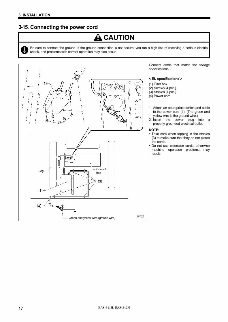
CAUTION Be sure to connect the ground. If the ground connection is not secure, you run a high risk of receiving a serious electric shock, and problems with correct operation may also occur.
Connect cords that match the voltage specifications. < EU specifications> (1) Filter box (2) Screws [4 pcs.] (3) Staples [4 pcs.] (4) Power cord 1. Attach an appropriate switch and cable
to the power cord (4). (The green and yellow wire is the ground wire.)
2. Insert the power plug into a properly-grounded electrical outlet.
NOTE: • Take care when tapping in the staples
(3) to make sure that they do not pierce the cords.
• Do not use extension cords, otherwise machine operation problems may result.
3673BGreen and yellow wire (ground wire)
Control box Leg
3. INSTALLATION
18BAS-341H, BAS-342H
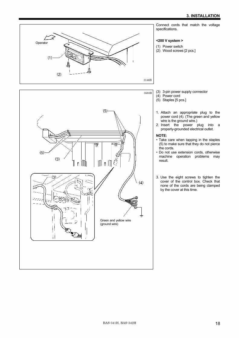
Connect cords that match the voltage specifications. <200 V system > (1) Power switch (2) Wood screws [2 pcs.]
(3) 3-pin power supply connector (4) Power cord (5) Staples [5 pcs.] 1. Attach an appropriate plug to the
power cord (4). (The green and yellow wire is the ground wire.)
2. Insert the power plug into a properly-grounded electrical outlet.
NOTE: • Take care when tapping in the staples
(5) to make sure that they do not pierce the cords.
• Do not use extension cords, otherwise machine operation problems may result.
3. Use the eight screws to tighten the
cover of the control box. Check that none of the cords are being clamped by the cover at this time.
Operator
3146B
3583B
Green and yellow wire (ground wire)
3. INSTALLATION
19 BAS-341H, BAS-342H
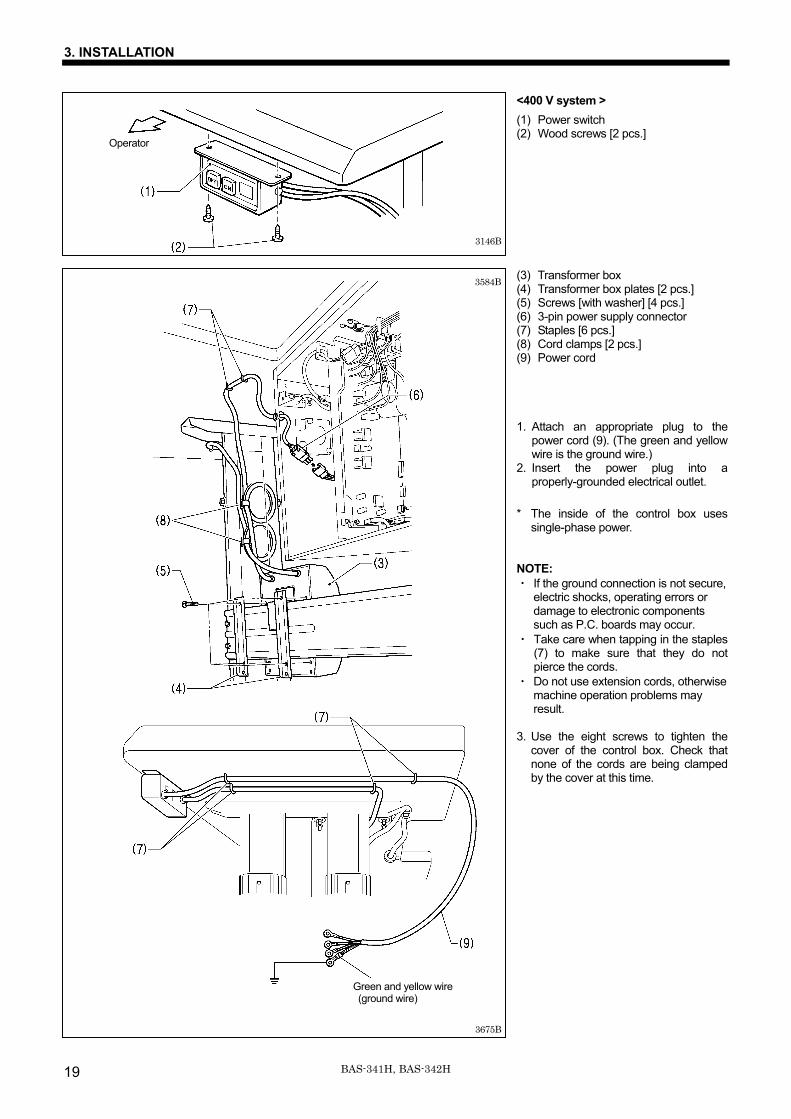
<400 V system > (1) Power switch (2) Wood screws [2 pcs.] (3) Transformer box (4) Transformer box plates [2 pcs.] (5) Screws [with washer] [4 pcs.] (6) 3-pin power supply connector (7) Staples [6 pcs.] (8) Cord clamps [2 pcs.] (9) Power cord 1. Attach an appropriate plug to the
power cord (9). (The green and yellow wire is the ground wire.)
2. Insert the power plug into a properly-grounded electrical outlet.
* The inside of the control box uses
single-phase power.
NOTE: ・ If the ground connection is not secure,
electric shocks, operating errors or damage to electronic components such as P.C. boards may occur.
・ Take care when tapping in the staples (7) to make sure that they do not pierce the cords.
・ Do not use extension cords, otherwise machine operation problems may result.
3. Use the eight screws to tighten the
cover of the control box. Check that none of the cords are being clamped by the cover at this time.
Green and yellow wire
(ground wire)
3146B
3584B
Operator
3675B
3. INSTALLATION
20BAS-341H, BAS-342H
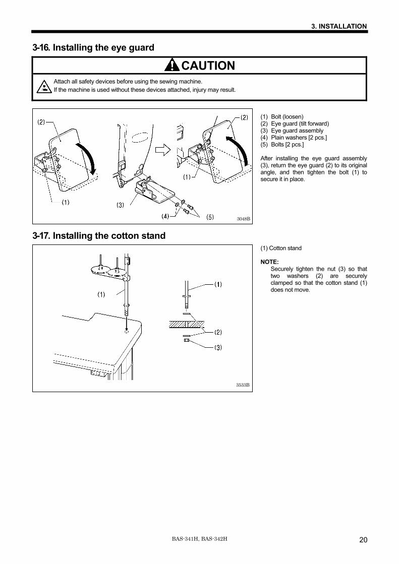
3-16. Installing the eye guard
CAUTION Attach all safety devices before using the sewing machine. If the machine is used without these devices attached, injury may result.
(1) Bolt (loosen) (2) Eye guard (tilt forward) (3) Eye guard assembly (4) Plain washers [2 pcs.] (5) Bolts [2 pcs.] After installing the eye guard assembly (3), return the eye guard (2) to its original angle, and then tighten the bolt (1) to secure it in place.
3-17. Installing the cotton stand (1) Cotton stand NOTE:
Securely tighten the nut (3) so that two washers (2) are securely clamped so that the cotton stand (1) does not move.
3533B
3048B
3. INSTALLATION
21 BAS-341H, BAS-342H
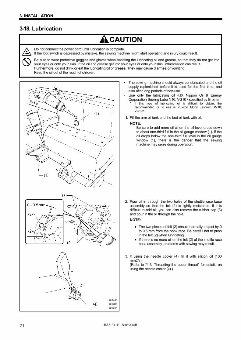
3-18. Lubrication
CAUTION Do not connect the power cord until lubrication is complete. If the foot switch is depressed by mistake, the sewing machine might start operating and injury could result.
Be sure to wear protective goggles and gloves when handling the lubricating oil and grease, so that they do not get into your eyes or onto your skin. If the oil and grease get into your eyes or onto your skin, inflammation can result. Furthermore, do not drink or eat the lubricating oil or grease. They may cause diarrhea or vomiting. Keep the oil out of the reach of children.
・ The sewing machine should always be lubricated and the oil supply replenished before it is used for the first time, and also after long periods of non-use.
・ Use only the lubricating oil <JX Nippon Oil & Energy Corporation Sewing Lube N10; VG10> specified by Brother. * If this type of lubricating oil is difficult to obtain, the
recommended oil to use is <Exxon Mobil Essotex SM10; VG10>.
1. Fill the arm oil tank and the bed oil tank with oil. NOTE:
Be sure to add more oil when the oil level drops down to about one-third full in the oil gauge window (1). If the oil drops below the one-third full level in the oil gauge window (1), there is the danger that the sewing machine may seize during operation.
2. Pour oil in through the two holes of the shuttle race base assembly so that the felt (2) is lightly moistened. If it is difficult to add oil, you can also remove the rubber cap (3) and pour in the oil through the hole. NOTE:
• The two pieces of felt (2) should normally project by 0 to 0.5 mm from the hook race. Be careful not to push in the felt (2) when lubricating.
• If there is no more oil on the felt (2) of the shuttle race base assembly, problems with sewing may result.
3. If using the needle cooler (4), fill it with silicon oil (100 mm2/s). (Refer to "4-3. Threading the upper thread" for details on using the needle cooler (4).)
3569B3531B3532B
3. INSTALLATION
22BAS-341H, BAS-342H
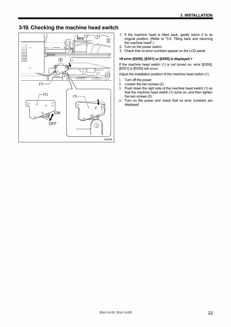
3-19. Checking the machine head switch 1. If the machine head is tilted back, gently return it to its
original position. (Refer to "3-5. Tilting back and returning the machine head".)
2. Turn on the power switch. 3. Check that no error numbers appear on the LCD panel.
<If error [E050], [E051] or [E055] is displayed > If the machine head switch (1) is not turned on, error [E050], [E051] or [E055] will occur. Adjust the installation position of the machine head switch (1). 1. Turn off the power. 2. Loosen the two screws (2). 3. Push down the right side of the machine head switch (1) so
that the machine head switch (1) turns on, and then tighten the two screws (2).
4. Turn on the power and check that no error numbers are displayed.
3989M
4. PREPARATION BEFORE SEWING
23 BAS-341H, BAS-342H
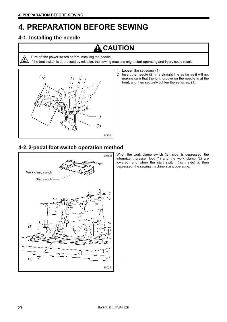
4. PREPARATION BEFORE SEWING 4-1. Installing the needle
CAUTION Turn off the power switch before installing the needle. If the foot switch is depressed by mistake, the sewing machine might start operating and injury could result.
1. Loosen the set screw (1). 2. Insert the needle (2) in a straight line as far as it will go,
making sure that the long groove on the needle is at the front, and then securely tighten the set screw (1).
4-2. 2-pedal foot switch operation method When the work clamp switch (left side) is depressed, the intermittent presser foot (1) and the work clamp (2) are lowered, and when the start switch (right side) is then depressed, the sewing machine starts operating.
.
3475B
Work clamp switch
Start switch
3991M
3502B
4. PREPARATION BEFORE SEWING
24BAS-341H, BAS-342H
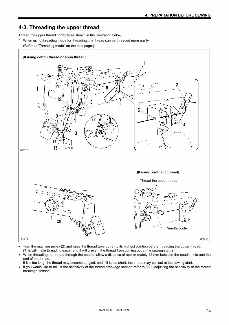
4-3. Threading the upper thread Thread the upper thread correctly as shown in the illustration below. * When using threading mode for threading, the thread can be threaded more easily.
(Refer to "Threading mode" on the next page.) • Turn the machine pulley (2) and raise the thread take-up (3) to its highest position before threading the upper thread.
(This will make threading easier and it will prevent the thread from coming out at the sewing start.) • When threading the thread through the needle, allow a distance of approximately 42 mm between the needle hole and the
end of the thread. If it is too long, the thread may become tangled, and if it is too short, the thread may pull out at the sewing start.
• If you would like to adjust the sensitivity of the thread breakage sensor, refer to "7-1. Adjusting the sensitivity of the thread breakage sensor”.
[If using cotton thread or spun thread]
3476B
3477B
[If using synthetic thread]
3586B
Thread the upper thread
Needle cooler
4. PREPARATION BEFORE SEWING
25 BAS-341H, BAS-342H
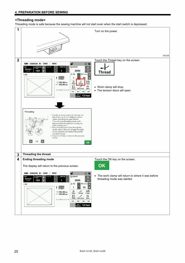
<Threading mode> Threading mode is safe because the sewing machine will not start even when the start switch is depressed.
1
Turn on the power.
2
Touch the Thread key on the screen.
• Work clamp will drop. • The tension discs will open.
3 Threading the thread.
4 Ending threading mode The display will return to the previous screen.
Touch the OK key on the screen.
• The work clamp will return to where it was before
threading mode was started.
3055B
4. PREPARATION BEFORE SEWING
26BAS-341H, BAS-342H
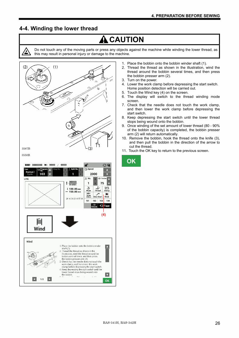
4-4. Winding the lower thread
CAUTION
Do not touch any of the moving parts or press any objects against the machine while winding the lower thread, as this may result in personal injury or damage to the machine.
1. Place the bobbin onto the bobbin winder shaft (1). 2. Thread the thread as shown in the illustration, wind the
thread around the bobbin several times, and then press the bobbin presser arm (2).
3. Turn on the power. 4. Lower the work clamp before depressing the start switch.
Home position detection will be carried out. 5. Touch the Wind key (4) on the screen. 6. The display will switch to the thread winding mode
screen. 7. Check that the needle does not touch the work clamp,
and then lower the work clamp before depressing the start switch.
8. Keep depressing the start switch until the lower thread stops being wound onto the bobbin.
9. Once winding of the set amount of lower thread (80 - 90% of the bobbin capacity) is completed, the bobbin presser arm (2) will return automatically.
10. Remove the bobbin, hook the thread onto the knife (3), and then pull the bobbin in the direction of the arrow to cut the thread.
11. Touch the OK key to return to the previous screen.
3550B
3587B
(4)
4. PREPARATION BEFORE SEWING
27 BAS-341H, BAS-342H
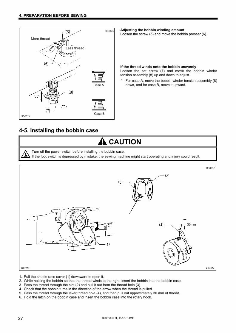
Adjusting the bobbin winding amount Loosen the screw (5) and move the bobbin presser (6). If the thread winds onto the bobbin unevenly Loosen the set screw (7) and move the bobbin winder tension assembly (8) up and down to adjust. * For case A, move the bobbin winder tension assembly (8)
down, and for case B, move it upward.
4-5. Installing the bobbin case
CAUTION Turn off the power switch before installing the bobbin case. If the foot switch is depressed by mistake, the sewing machine might start operating and injury could result.
1. Pull the shuttle race cover (1) downward to open it. 2. While holding the bobbin so that the thread winds to the right, insert the bobbin into the bobbin case. 3. Pass the thread through the slot (2) and pull it out from the thread hole (3). 4. Check that the bobbin turns in the direction of the arrow when the thread is pulled. 5. Pass the thread through the lever thread hole (4), and then pull out approximately 30 mm of thread. 6. Hold the latch on the bobbin case and insert the bobbin case into the rotary hook.
4002M
2534Q
2535Q
30mm
3566B
3567B
More thread
Less thread
Case B
Case A
4. PREPARATION BEFORE SEWING
28BAS-341H, BAS-342H
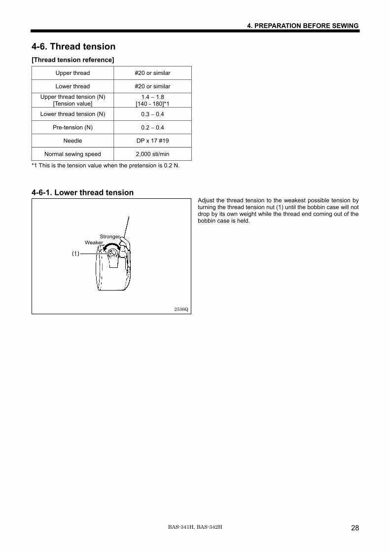
4-6. Thread tension [Thread tension reference]
Upper thread #20 or similar
Lower thread #20 or similar
Upper thread tension (N) [Tension value]
1.4 − 1.8 [140 - 180]*1
Lower thread tension (N) 0.3 − 0.4
Pre-tension (N) 0.2 − 0.4
Needle DP x 17 #19
Normal sewing speed 2,000 sti/min
*1 This is the tension value when the pretension is 0.2 N. 4-6-1. Lower thread tension
Adjust the thread tension to the weakest possible tension by turning the thread tension nut (1) until the bobbin case will not drop by its own weight while the thread end coming out of the bobbin case is held.
2536Q
StrongerWeaker
4. PREPARATION BEFORE SEWING
29 BAS-341H, BAS-342H
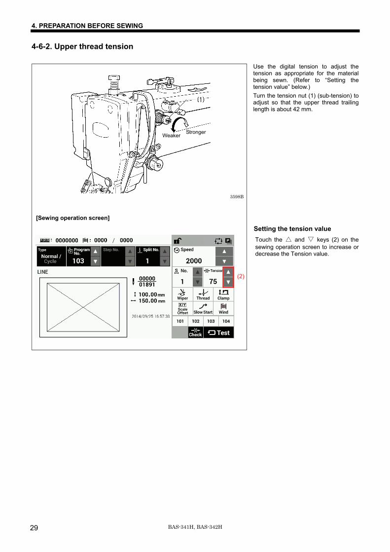
4-6-2. Upper thread tension
Use the digital tension to adjust the tension as appropriate for the material being sewn. (Refer to “Setting the tension value” below.) Turn the tension nut (1) (sub-tension) to adjust so that the upper thread trailing length is about 42 mm.
Setting the tension value Touch the △ and ▽ keys (2) on the sewing operation screen to increase or decrease the Tension value.
3598B
Weaker Stronger
[Sewing operation screen]
(2)
4. PREPARATION BEFORE SEWING
30BAS-341H, BAS-342H
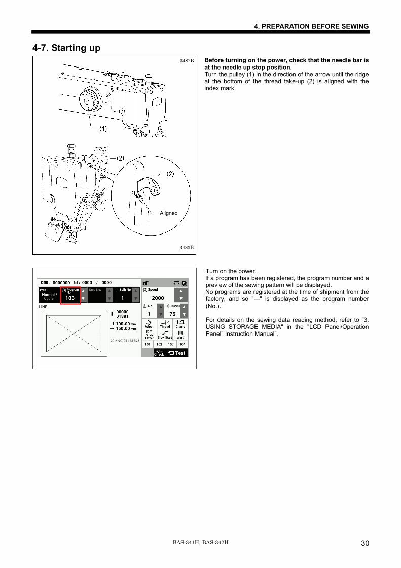
4-7. Starting up Before turning on the power, check that the needle bar is at the needle up stop position. Turn the pulley (1) in the direction of the arrow until the ridge at the bottom of the thread take-up (2) is aligned with the index mark.
Turn on the power. If a program has been registered, the program number and a preview of the sewing pattern will be displayed. No programs are registered at the time of shipment from the factory, and so "---" is displayed as the program number (No.). For details on the sewing data reading method, refer to "3. USING STORAGE MEDIA" in the "LCD Panel/Operation Panel" Instruction Manual".
3482B
3483B
Aligned
4. PREPARATION BEFORE SEWING
31 BAS-341H, BAS-342H
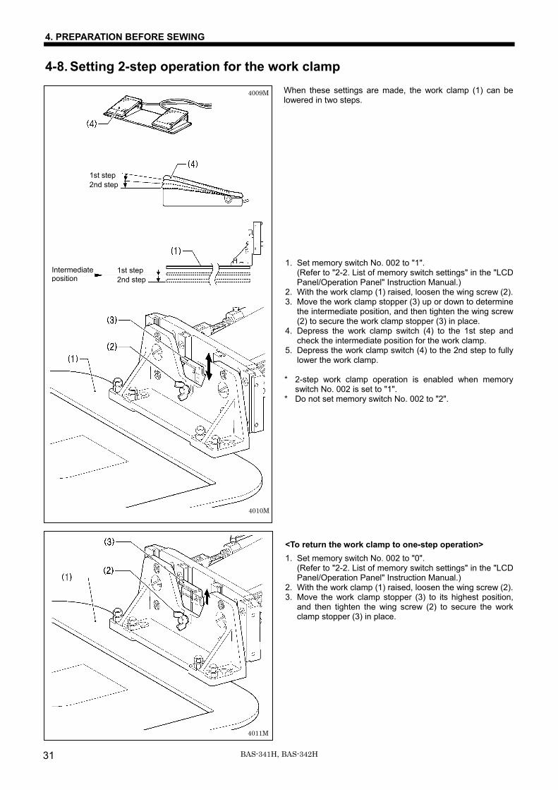
4-8. Setting 2-step operation for the work clamp When these settings are made, the work clamp (1) can be lowered in two steps. 1. Set memory switch No. 002 to "1".
(Refer to "2-2. List of memory switch settings" in the "LCD Panel/Operation Panel" Instruction Manual.)
2. With the work clamp (1) raised, loosen the wing screw (2). 3. Move the work clamp stopper (3) up or down to determine
the intermediate position, and then tighten the wing screw (2) to secure the work clamp stopper (3) in place.
4. Depress the work clamp switch (4) to the 1st step and check the intermediate position for the work clamp.
5. Depress the work clamp switch (4) to the 2nd step to fully lower the work clamp.
* 2-step work clamp operation is enabled when memory
switch No. 002 is set to "1". * Do not set memory switch No. 002 to "2". <To return the work clamp to one-step operation> 1. Set memory switch No. 002 to "0".
(Refer to "2-2. List of memory switch settings" in the "LCD Panel/Operation Panel" Instruction Manual.)
2. With the work clamp (1) raised, loosen the wing screw (2). 3. Move the work clamp stopper (3) to its highest position,
and then tighten the wing screw (2) to secure the work clamp stopper (3) in place.
1st step 2nd step
1st step 2nd step
4009M
4010M
4011M
Intermediate position
5. SEWING
32BAS-341H, BAS-342H
5. SEWING WARNING
Do not allow any liquids to get onto this sewing machine, otherwise fire, electric shocks or operating problems may occur. If any liquid gets inside the sewing machine (machine head or control box), immediately turn off the power and disconnect the power plug from the electrical outlet, and then contact the place of purchase or a qualified technician.
CAUTION Turn off the power switch at the following times. If the foot switch is depressed by mistake, the sewing machine might start operating and injury could result. • When replacing the bobbin and needle • When not using the machine and when leaving the machine unattended Do not touch any of the moving parts or press any objects against the machine while sewing, as this may result in personal injury or damage to the machine.
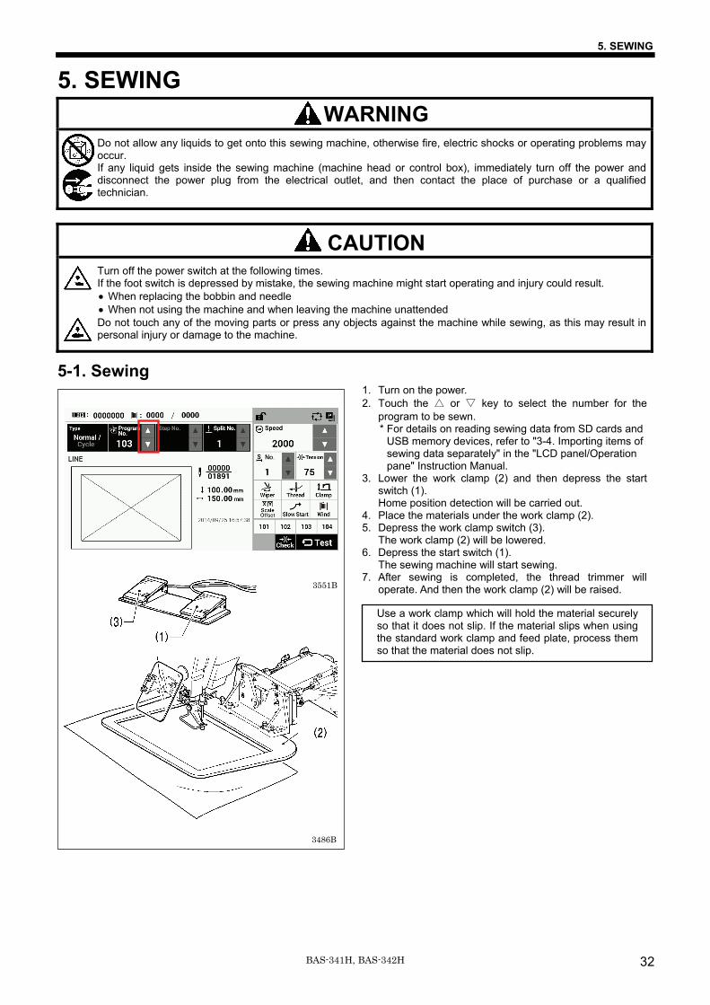
5-1. Sewing 1. Turn on the power. 2. Touch the △ or ▽ key to select the number for the
program to be sewn. * For details on reading sewing data from SD cards and
USB memory devices, refer to "3-4. Importing items of sewing data separately" in the "LCD panel/Operation pane" Instruction Manual.
3. Lower the work clamp (2) and then depress the start switch (1). Home position detection will be carried out.
4. Place the materials under the work clamp (2). 5. Depress the work clamp switch (3).
The work clamp (2) will be lowered. 6. Depress the start switch (1).
The sewing machine will start sewing. 7. After sewing is completed, the thread trimmer will
operate. And then the work clamp (2) will be raised.
Use a work clamp which will hold the material securely so that it does not slip. If the material slips when using the standard work clamp and feed plate, process them so that the material does not slip.
3551B
3486B
5. SEWING
33 BAS-341H, BAS-342H
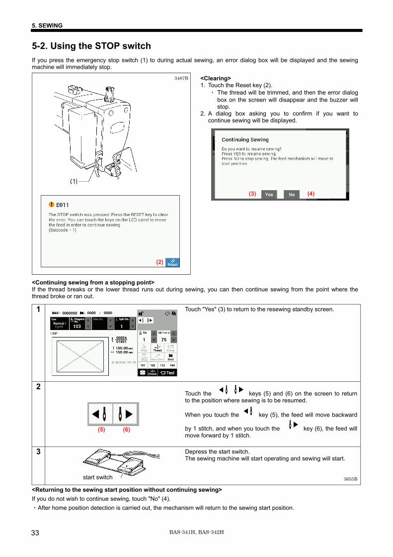
5-2. Using the STOP switch If you press the emergency stop switch (1) to during actual sewing, an error dialog box will be displayed and the sewing machine will immediately stop.
<Clearing> 1. Touch the Reset key (2).
・ The thread will be trimmed, and then the error dialog box on the screen will disappear and the buzzer will stop.
2. A dialog box asking you to confirm if you want to continue sewing will be displayed.
<Continuing sewing from a stopping point> If the thread breaks or the lower thread runs out during sewing, you can then continue sewing from the point where the thread broke or ran out.
1 Touch "Yes" (3) to return to the resewing standby screen.
2
Touch the keys (5) and (6) on the screen to return to the position where sewing is to be resumed.
When you touch the key (5), the feed will move backward
by 1 stitch, and when you touch the key (6), the feed will move forward by 1 stitch.
3 Depress the start switch. The sewing machine will start operating and sewing will start.
<Returning to the sewing start position without continuing sewing> If you do not wish to continue sewing, touch "No" (4). ・After home position detection is carried out, the mechanism will return to the sewing start position.
3655B
3487B
(3) (4)
(2)
(5) (6)
start switch
6. CLEANING
34BAS-341H, BAS-342H
6. CLEANING CAUTION
Turn off the power switch before carrying out cleaning. If the foot switch is depressed by mistake, the sewing machine might start operating and injury could result. Be sure to wear protective goggles and gloves when handling the lubricating oil and grease, so that they do not get into your eyes or onto your skin. If the oil and grease get into your eyes or onto your skin, inflammation can result. Furthermore, do not drink or eat the lubricating oil or grease. They may cause diarrhea or vomiting. Keep the oil out of the reach of children.
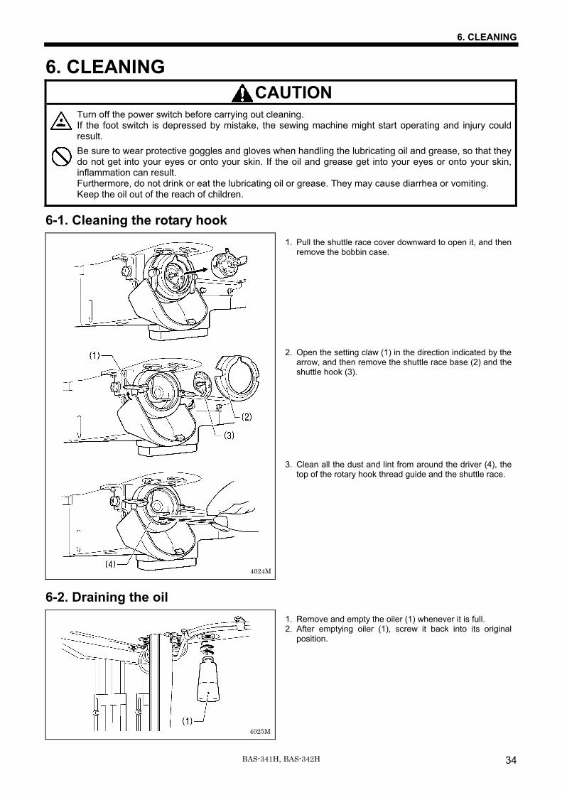
6-1. Cleaning the rotary hook 1. Pull the shuttle race cover downward to open it, and then
remove the bobbin case.
2. Open the setting claw (1) in the direction indicated by the arrow, and then remove the shuttle race base (2) and the shuttle hook (3).
3. Clean all the dust and lint from around the driver (4), the top of the rotary hook thread guide and the shuttle race.
6-2. Draining the oil
1. Remove and empty the oiler (1) whenever it is full. 2. After emptying oiler (1), screw it back into its original
position.
4025M
4024M
6. CLEANING
35 BAS-341H, BAS-342H
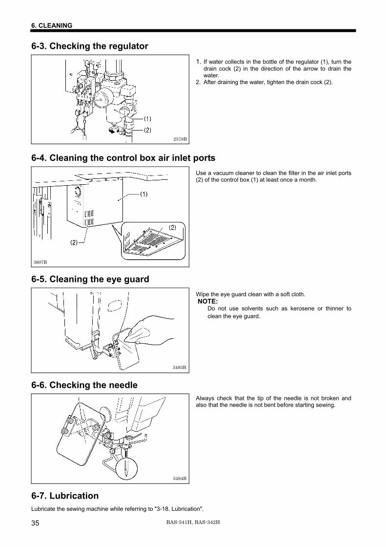
6-3. Checking the regulator
1. If water collects in the bottle of the regulator (1), turn the drain cock (2) in the direction of the arrow to drain the water.
2. After draining the water, tighten the drain cock (2).
6-4. Cleaning the control box air inlet ports
Use a vacuum cleaner to clean the filter in the air inlet ports (2) of the control box (1) at least once a month.
6-5. Cleaning the eye guard
Wipe the eye guard clean with a soft cloth. NOTE:
Do not use solvents such as kerosene or thinner to clean the eye guard.
6-6. Checking the needle
Always check that the tip of the needle is not broken and also that the needle is not bent before starting sewing.
6-7. Lubrication Lubricate the sewing machine while referring to "3-18. Lubrication".
3494B
2578B
3607B
3493B
7. STANDARD ADJUSTMENTS
36BAS-341H, BAS-342H
7. STANDARD ADJUSTMENTS CAUTION
Maintenance and inspection of the sewing machine should only be carried out by a qualified technician. Ask your Brother dealer or a qualified electrician to carry out any maintenance and inspection of the electrical system. Turn off the power switch and disconnect the power cord before carrying out the following operations. If the foot switch is depressed by mistake, the sewing achine might start operating and injury could result. ・ Inspection, adjustment and maintenance ・ Replacing consumable parts such as the rotary
hook Disconnect the air hoses from the air supply and wait for the needle on the pressure gauge to drop to "0" before carrying out inspection, adjustment and repair of any parts which use the pneumatic equipment. If the power switch and air need to be left on when carrying out some adjustment, be extremely careful to observe all safety precautions.
Hold the machine head with both hands when tilting it back or returning it to its original position. In addition, do not subject the machine head to extra force while it is tilted back. If this is not observed, the machine head may become unbalanced and fall down, and serious injury or damage to the sewing machine may result. Be sure to wear protective goggles and gloves when handling the lubricating oil and grease, so that they do not get into your eyes or onto your skin. If the oil and grease get into your eyes or onto your skin, inflammation can result. Furthermore, do not drink or eat the lubricating oil or grease. They may cause diarrhea or vomiting. Keep the oil out of the reach of children. If any safety devices have been removed, be absolutely sure to re-install them to their original positions and check that they operate correctly before using the machine.
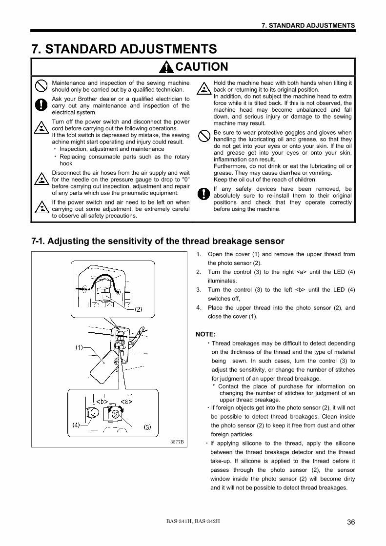
7-1. Adjusting the sensitivity of the thread breakage sensor 1. Open the cover (1) and remove the upper thread from
the photo sensor (2). 2. Turn the control (3) to the right <a> until the LED (4)
illuminates. 3. Turn the control (3) to the left <b> until the LED (4)
switches off, 4. Place the upper thread into the photo sensor (2), and
close the cover (1).
NOTE: ・Thread breakages may be difficult to detect depending
on the thickness of the thread and the type of material being sewn. In such cases, turn the control (3) to adjust the sensitivity, or change the number of stitches for judgment of an upper thread breakage.
* Contact the place of purchase for information on changing the number of stitches for judgment of an upper thread breakage.
・If foreign objects get into the photo sensor (2), it will not be possible to detect thread breakages. Clean inside the photo sensor (2) to keep it free from dust and other foreign particles.
・ If applying silicone to the thread, apply the silicone between the thread breakage detector and the thread take-up. If silicone is applied to the thread before it passes through the photo sensor (2), the sensor window inside the photo sensor (2) will become dirty and it will not be possible to detect thread breakages.
3577B
7. STANDARD ADJUSTMENTS
37 BAS-341H, BAS-342H
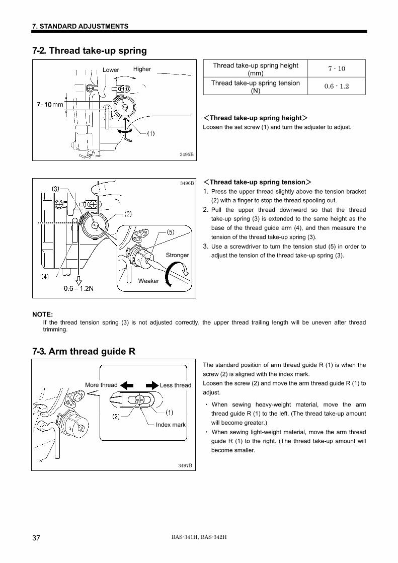
7-2. Thread take-up spring Thread take-up spring height
(mm) 7 - 10
Thread take-up spring tension (N)
0.6 - 1.2
<Thread take-up spring height> Loosen the set screw (1) and turn the adjuster to adjust. <Thread take-up spring tension> 1. Press the upper thread slightly above the tension bracket
(2) with a finger to stop the thread spooling out. 2. Pull the upper thread downward so that the thread
take-up spring (3) is extended to the same height as the base of the thread guide arm (4), and then measure the tension of the thread take-up spring (3).
3. Use a screwdriver to turn the tension stud (5) in order to adjust the tension of the thread take-up spring (3).
NOTE: If the thread tension spring (3) is not adjusted correctly, the upper thread trailing length will be uneven after thread trimming.
7-3. Arm thread guide R The standard position of arm thread guide R (1) is when the screw (2) is aligned with the index mark. Loosen the screw (2) and move the arm thread guide R (1) to adjust.
・ When sewing heavy-weight material, move the arm thread guide R (1) to the left. (The thread take-up amount will become greater.)
・ When sewing light-weight material, move the arm thread guide R (1) to the right. (The thread take-up amount will become smaller.
Weaker
Stronger
3496B
Lower Higher
3497B
More thread Less thread
Index mark
3495B
7. STANDARD ADJUSTMENTS
38BAS-341H, BAS-342H
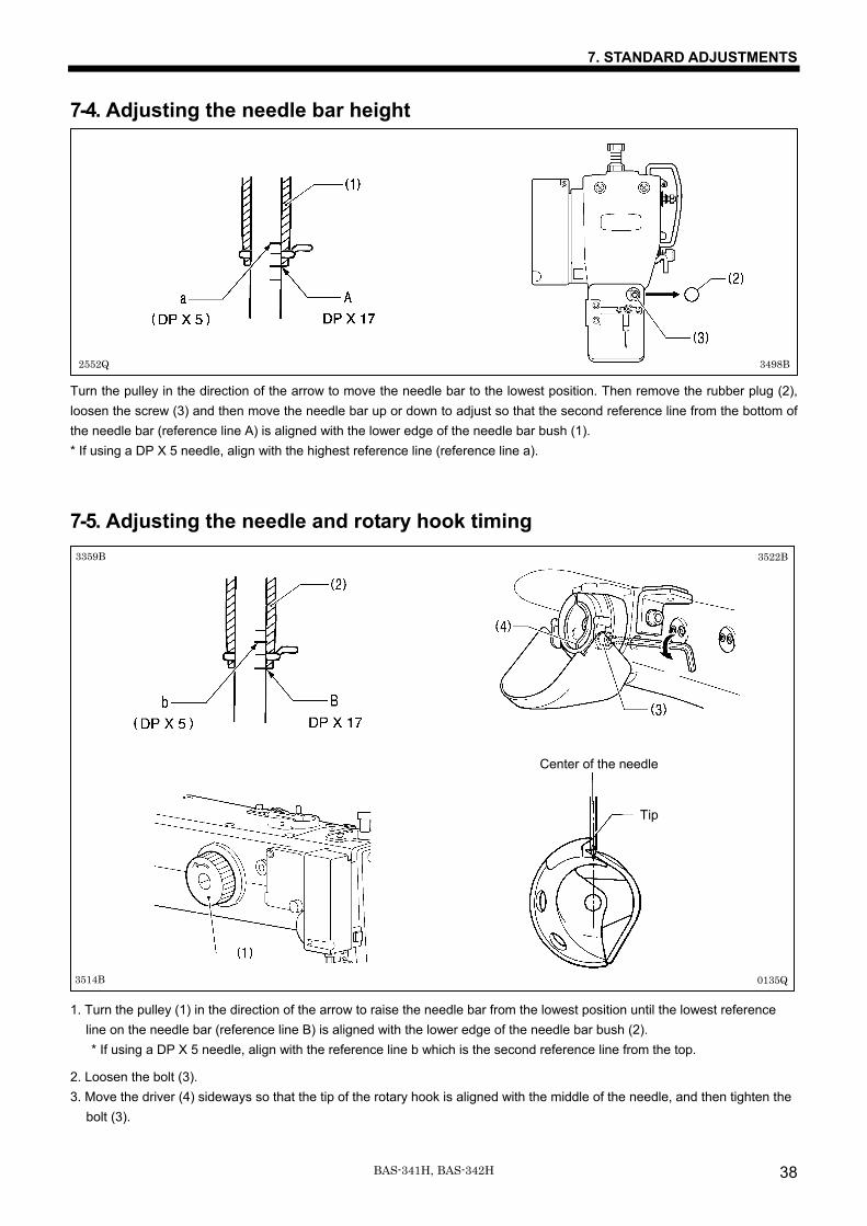
7-4. Adjusting the needle bar height
Turn the pulley in the direction of the arrow to move the needle bar to the lowest position. Then remove the rubber plug (2), loosen the screw (3) and then move the needle bar up or down to adjust so that the second reference line from the bottom of the needle bar (reference line A) is aligned with the lower edge of the needle bar bush (1). * If using a DP X 5 needle, align with the highest reference line (reference line a).
7-5. Adjusting the needle and rotary hook timing
1. Turn the pulley (1) in the direction of the arrow to raise the needle bar from the lowest position until the lowest reference line on the needle bar (reference line B) is aligned with the lower edge of the needle bar bush (2). * If using a DP X 5 needle, align with the reference line b which is the second reference line from the top.
2. Loosen the bolt (3). 3. Move the driver (4) sideways so that the tip of the rotary hook is aligned with the middle of the needle, and then tighten the
bolt (3).
2552Q 3498B
3359B 3522B
Center of the needle
Tip
3514B 0135Q
7. STANDARD ADJUSTMENTS
39 BAS-341H, BAS-342H
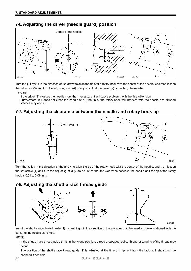
7-6. Adjusting the driver (needle guard) position Turn the pulley (1) in the direction of the arrow to align the tip of the rotary hook with the center of the needle, and then loosen the set screw (3) and turn the adjusting stud (4) to adjust so that the driver (2) is touching the needle.
NOTE: If the driver (2) crosses the needle more than necessary, it will cause problems with the thread tension. Furthermore, if it does not cross the needle at all, the tip of the rotary hook will interfere with the needle and skipped stitches may occur.
7-7. Adjusting the clearance between the needle and rotary hook tip Turn the pulley in the direction of the arrow to align the tip of the rotary hook with the center of the needle, and then loosen the set screw (1) and turn the adjusting stud (2) to adjust so that the clearance between the needle and the tip of the rotary hook is 0.01 to 0.08 mm.
7-8. Adjusting the shuttle race thread guide
Install the shuttle race thread guide (1) by pushing it in the direction of the arrow so that the needle groove is aligned with the center of the needle plate hole. NOTE:
If the shuttle race thread guide (1) is in the wrong position, thread breakages, soiled thread or tangling of the thread may occur. The position of the shuttle race thread guide (1) is adjusted at the time of shipment from the factory. It should not be changed if possible.
0.01 - 0.08mm
3574Q
0138Q 4035M
Center of the needle
Tip
0135Q 3515B 3516B 3514B
7. STANDARD ADJUSTMENTS
40BAS-341H, BAS-342H
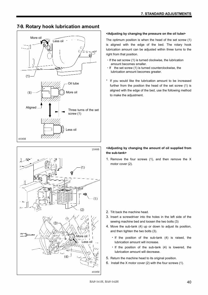
7-9. Rotary hook lubrication amount <Adjusting by changing the pressure on the oil tube>
The optimum position is when the head of the set screw (1) is aligned with the edge of the bed. The rotary hook lubrication amount can be adjusted within three turns to the right from that position.
・If the set screw (1) is turned clockwise, the lubrication amount becomes smaller. ・If the set screw (1) is turned counterclockwise, the lubrication amount becomes greater. * If you would like the lubrication amount to be increased
further from the position the head of the set screw (1) is aligned with the edge of the bed, use the following method to make the adjustment.
<Adjusting by changing the amount of oil supplied from the sub-tank>
1. Remove the four screws (1), and then remove the X motor cover (2).
2. Tilt back the machine head. 3. Insert a screwdriver into the holes in the left side of the
sewing machine bed and loosen the two bolts (3) 4. Move the sub-tank (4) up or down to adjust its position,
and then tighten the two bolts (3). ・ If the position of the sub-tank (4) is raised, the
lubrication amount will increase. ・ If the position of the sub-tank (4) is lowered, the
lubrication amount will decrease.
5. Return the machine head to its original position. 6. Install the X motor cover (2) with the four screws (1).
2589B
4038M
Less oil
More oil
4036M
Aligned
Oil tube
Three turns of the set screw (1)
More oil
Less oil
Less oilMore oil
7. STANDARD ADJUSTMENTS
41 BAS-341H, BAS-342H
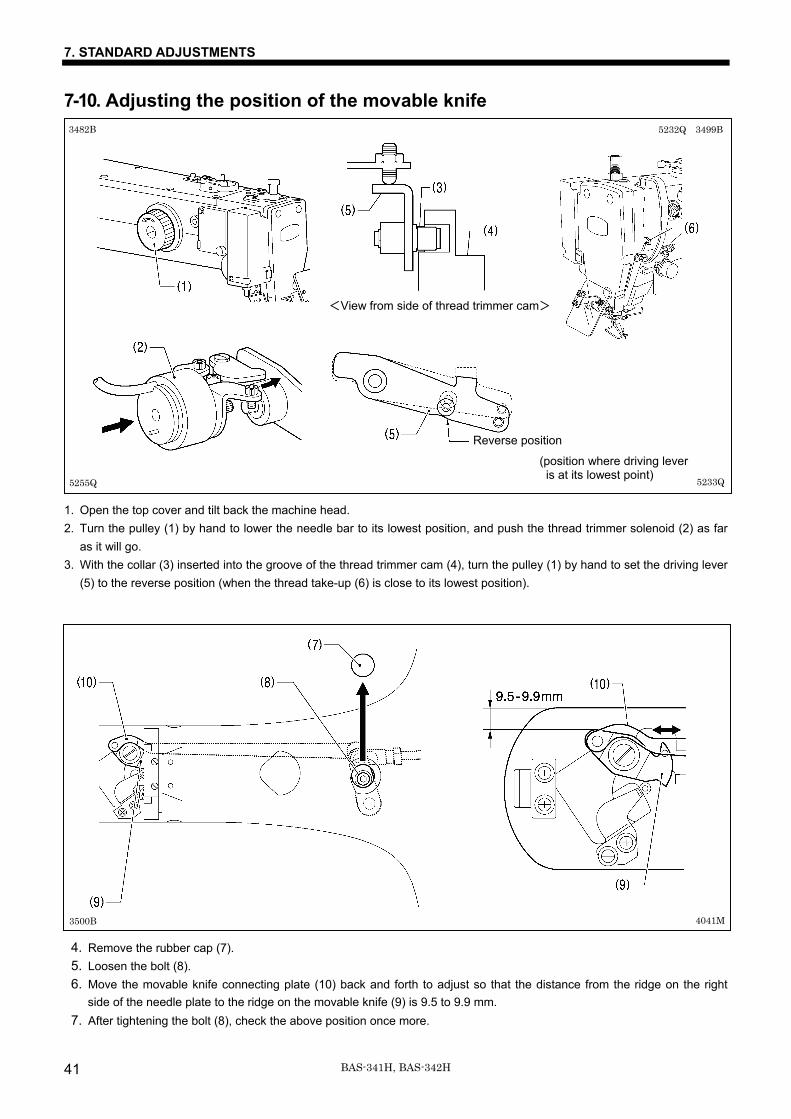
7-10. Adjusting the position of the movable knife 1. Open the top cover and tilt back the machine head. 2. Turn the pulley (1) by hand to lower the needle bar to its lowest position, and push the thread trimmer solenoid (2) as far
as it will go. 3. With the collar (3) inserted into the groove of the thread trimmer cam (4), turn the pulley (1) by hand to set the driving lever
(5) to the reverse position (when the thread take-up (6) is close to its lowest position).
4. Remove the rubber cap (7). 5. Loosen the bolt (8). 6. Move the movable knife connecting plate (10) back and forth to adjust so that the distance from the ridge on the right
side of the needle plate to the ridge on the movable knife (9) is 9.5 to 9.9 mm. 7. After tightening the bolt (8), check the above position once more.
<View from side of thread trimmer cam>
5255Q 5233Q
Reverse position
5232Q 3499B 3482B
3500B 4041M
(position where driving lever is at its lowest point)
7. STANDARD ADJUSTMENTS
42BAS-341H, BAS-342H
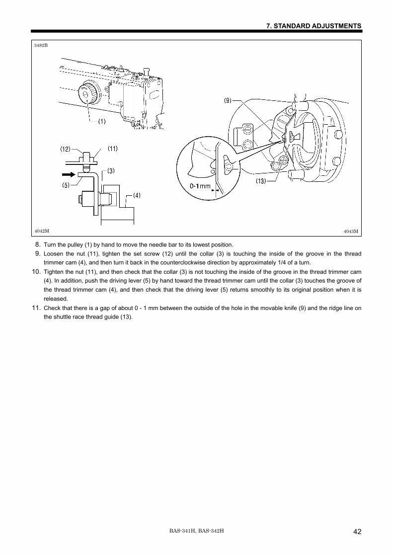
8. Turn the pulley (1) by hand to move the needle bar to its lowest position. 9. Loosen the nut (11), tighten the set screw (12) until the collar (3) is touching the inside of the groove in the thread
trimmer cam (4), and then turn it back in the counterclockwise direction by approximately 1/4 of a turn. 10. Tighten the nut (11), and then check that the collar (3) is not touching the inside of the groove in the thread trimmer cam
(4). In addition, push the driving lever (5) by hand toward the thread trimmer cam until the collar (3) touches the groove of the thread trimmer cam (4), and then check that the driving lever (5) returns smoothly to its original position when it is released.
11. Check that there is a gap of about 0 - 1 mm between the outside of the hole in the movable knife (9) and the ridge line on the shuttle race thread guide (13).
3482B
4042M 4043M
7. STANDARD ADJUSTMENTS
43 BAS-341H, BAS-342H
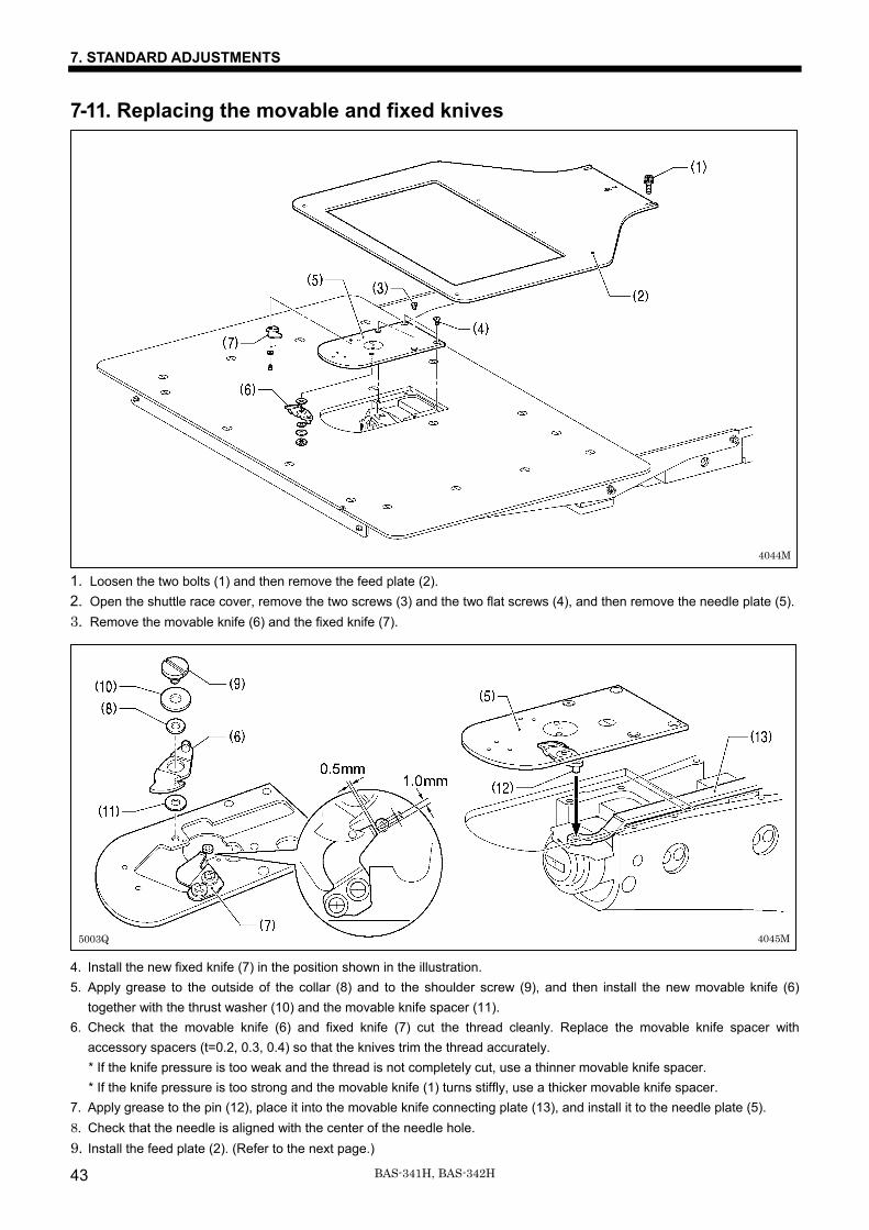
7-11. Replacing the movable and fixed knives
1. Loosen the two bolts (1) and then remove the feed plate (2). 2. Open the shuttle race cover, remove the two screws (3) and the two flat screws (4), and then remove the needle plate (5). 3. Remove the movable knife (6) and the fixed knife (7). 4. Install the new fixed knife (7) in the position shown in the illustration. 5. Apply grease to the outside of the collar (8) and to the shoulder screw (9), and then install the new movable knife (6)
together with the thrust washer (10) and the movable knife spacer (11). 6. Check that the movable knife (6) and fixed knife (7) cut the thread cleanly. Replace the movable knife spacer with
accessory spacers (t=0.2, 0.3, 0.4) so that the knives trim the thread accurately. * If the knife pressure is too weak and the thread is not completely cut, use a thinner movable knife spacer. * If the knife pressure is too strong and the movable knife (1) turns stiffly, use a thicker movable knife spacer.
7. Apply grease to the pin (12), place it into the movable knife connecting plate (13), and install it to the needle plate (5). 8. Check that the needle is aligned with the center of the needle hole. 9. Install the feed plate (2). (Refer to the next page.)
5003Q
4044M
4045M
7. STANDARD ADJUSTMENTS
44BAS-341H, BAS-342H
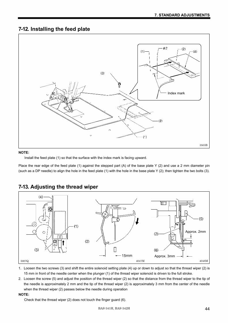
7-12. Installing the feed plate NOTE:
Install the feed plate (1) so that the surface with the index mark is facing upward.
Place the rear edge of the feed plate (1) against the stepped part (A) of the base plate Y (2) and use a 2 mm diameter pin (such as a DP needle) to align the hole in the feed plate (1) with the hole in the base plate Y (2); then tighten the two bolts (3).
7-13. Adjusting the thread wiper 1. Loosen the two screws (3) and shift the entire solenoid setting plate (4) up or down to adjust so that the thread wiper (2) is
15 mm in front of the needle center when the plunger (1) of the thread wiper solenoid is driven to the full stroke. 2. Loosen the screw (5) and adjust the position of the thread wiper (2) so that the distance from the thread wiper to the tip of
the needle is approximately 2 mm and the tip of the thread wiper (2) is approximately 3 mm from the center of the needle when the thread wiper (2) passes below the needle during operation
NOTE: Check that the thread wiper (2) does not touch the finger guard (6).
5007Q 4048MApprox. 3mm
Approx. 2mm
Index mark
3503B
4047M
7. STANDARD ADJUSTMENTS
45 BAS-341H, BAS-342H
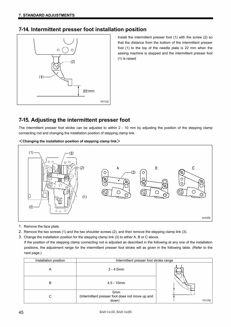
7-14. Intermittent presser foot installation position Install the intermittent presser foot (1) with the screw (2) so that the distance from the bottom of the intermittent presser foot (1) to the top of the needle plate is 22 mm when the sewing machine is stopped and the intermittent presser foot (1) is raised
7-15. Adjusting the intermittent presser foot The intermittent presser foot stroke can be adjusted to within 2 - 10 mm by adjusting the position of the stepping clamp connecting rod and changing the installation position of stepping clamp link.
<Changing the installation position of stepping clamp link> 1. Remove the face plate. 2. Remove the two screws (1) and the two shoulder screws (2), and then remove the stepping clamp link (3). 3. Change the installation position for the stepping clamp link (3) to either A, B or C above.
If the position of the stepping clamp connecting rod is adjusted as described in the following at any one of the installation positions, the adjustment range for the intermittent presser foot stroke will as given in the following table. (Refer to the next page.)
Installation position Intermittent presser foot stroke range
A 2 - 4.5mm
B 4.5 - 10mm
C 0mm
(Intermittent presser foot does not move up and down)
5012Q
5031Q
4049M
7. STANDARD ADJUSTMENTS
46BAS-341H, BAS-342H
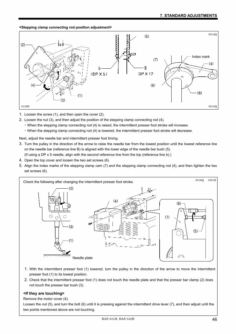
<Stepping clamp connecting rod position adjustment> 1. Loosen the screw (1), and then open the cover (2). 2. Loosen the nut (3), and then adjust the position of the stepping clamp connecting rod (4).
・When the stepping clamp connecting rod (4) is raised, the intermittent presser foot stroke will increase. ・When the stepping clamp connecting rod (4) is lowered, the intermittent presser foot stroke will decrease.
Next, adjust the needle bar and intermittent presser foot timing. 3. Turn the pulley in the direction of the arrow to raise the needle bar from the lowest position until the lowest reference line
on the needle bar (reference line B) is aligned with the lower edge of the needle bar bush (5). (If using a DP x 5 needle, align with the second reference line from the top (reference line b).)
4. Open the top cover and loosen the two set screws (6). 5. Align the index marks of the stepping clamp cam (7) and the stepping clamp connecting rod (4), and then tighten the two
set screws (6).
Check the following after changing the intermittent presser foot stroke. 1. With the intermittent presser foot (1) lowered, turn the pulley in the direction of the arrow to move the intermittent
presser foot (1) to its lowest position. 2. Check that the intermittent presser foot (1) does not touch the needle plate and that the presser bar clamp (2) does
not touch the presser bar bush (3).
<If they are touching> Remove the motor cover (4). Loosen the nut (5), and turn the bolt (6) until it is pressing against the intermittent drive lever (7), and then adjust until the two points mentioned above are not touching.
5015Q
5014Q
5016Q 3501B
Needle plate
Index mark
3138B
7. STANDARD ADJUSTMENTS
47 BAS-341H, BAS-342H
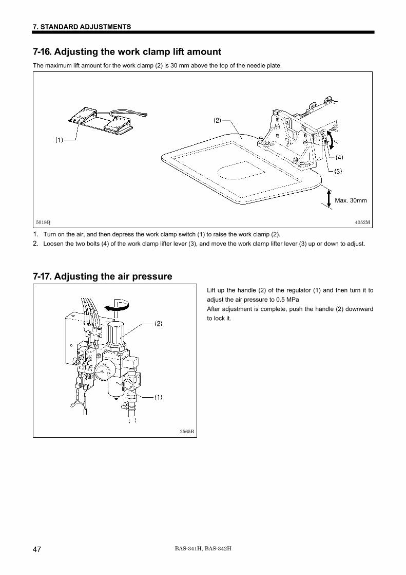
7-16. Adjusting the work clamp lift amount The maximum lift amount for the work clamp (2) is 30 mm above the top of the needle plate. 1. Turn on the air, and then depress the work clamp switch (1) to raise the work clamp (2). 2. Loosen the two bolts (4) of the work clamp lifter lever (3), and move the work clamp lifter lever (3) up or down to adjust.
7-17. Adjusting the air pressure Lift up the handle (2) of the regulator (1) and then turn it to adjust the air pressure to 0.5 MPa After adjustment is complete, push the handle (2) downward to lock it.
5018Q 4052M
Max. 30mm
2565B
7. STANDARD ADJUSTMENTS
48BAS-341H, BAS-342H
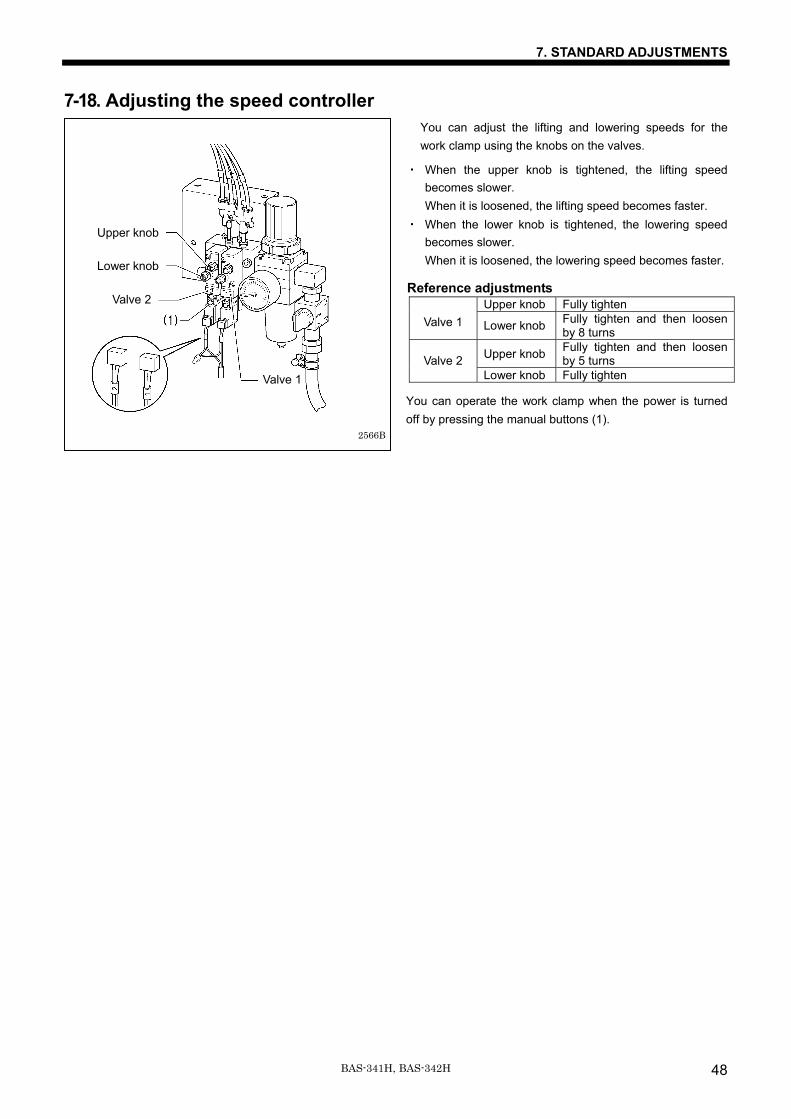
7-18. Adjusting the speed controller You can adjust the lifting and lowering speeds for the work clamp using the knobs on the valves.
・ When the upper knob is tightened, the lifting speed becomes slower. When it is loosened, the lifting speed becomes faster.
・ When the lower knob is tightened, the lowering speed becomes slower. When it is loosened, the lowering speed becomes faster.
Reference adjustments Upper knob Fully tighten
Valve 1 Lower knob Fully tighten and then loosen by 8 turns
Upper knob Fully tighten and then loosen by 5 turns
Valve 2
Lower knob Fully tighten
You can operate the work clamp when the power is turned off by pressing the manual buttons (1).
Upper knob
Lower knob
Valve 1
2566B
Valve 2
7. STANDARD ADJUSTMENTS
49 BAS-341H, BAS-342H
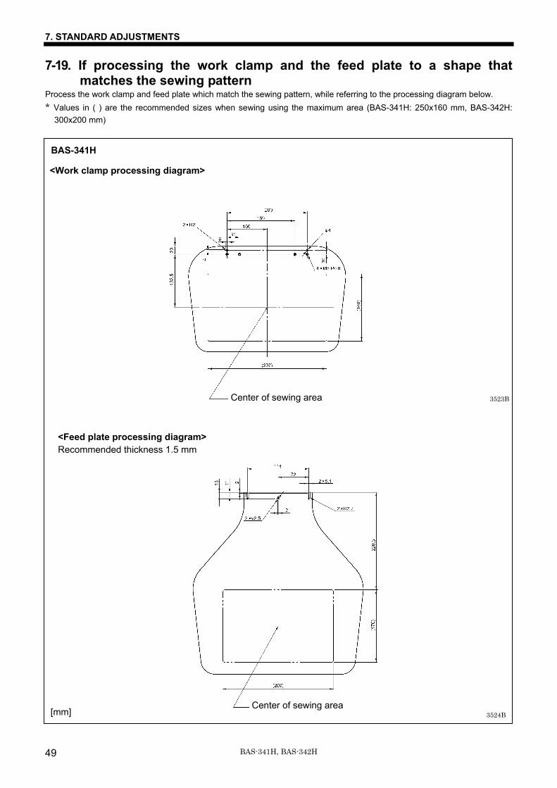
7-19. If processing the work clamp and the feed plate to a shape that matches the sewing pattern
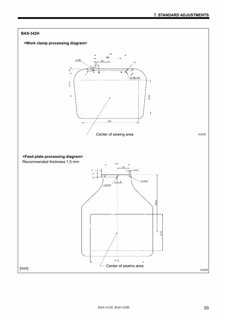
Process the work clamp and feed plate which match the sewing pattern, while referring to the processing diagram below. * Values in ( ) are the recommended sizes when sewing using the maximum area (BAS-341H: 250x160 mm, BAS-342H:
300x200 mm)
BAS-341H
<Work clamp processing diagram>
<Feed plate processing diagram> Recommended thickness 1.5 mm
3523B
3524B
Center of sewing area
Center of sewing area [mm]
7. STANDARD ADJUSTMENTS
50BAS-341H, BAS-342H
BAS-342H
<Work clamp processing diagram>
<Feed plate processing diagram> Recommended thickness 1.5 mm
3525B
3526B
Center of sewing area
Center of sewing area[mm]
8. LIST OF ERROR CODES
BAS-341H, BAS-342H51
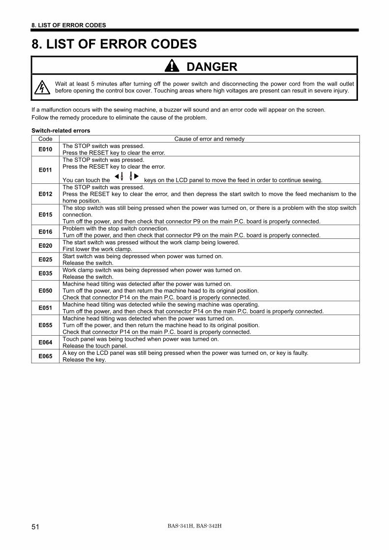
8. LIST OF ERROR CODES DANGER
Wait at least 5 minutes after turning off the power switch and disconnecting the power cord from the wall outlet before opening the control box cover. Touching areas where high voltages are present can result in severe injury.
If a malfunction occurs with the sewing machine, a buzzer will sound and an error code will appear on the screen. Follow the remedy procedure to eliminate the cause of the problem.
Switch-related errors Code Cause of error and remedy
E010 The STOP switch was pressed. Press the RESET key to clear the error.
E011 The STOP switch was pressed. Press the RESET key to clear the error.
You can touch the keys on the LCD panel to move the feed in order to continue sewing.
E012 The STOP switch was pressed. Press the RESET key to clear the error, and then depress the start switch to move the feed mechanism to the home position.
E015 The stop switch was still being pressed when the power was turned on, or there is a problem with the stop switch connection. Turn off the power, and then check that connector P9 on the main P.C. board is properly connected.
E016 Problem with the stop switch connection. Turn off the power, and then check that connector P9 on the main P.C. board is properly connected.
E020 The start switch was pressed without the work clamp being lowered. First lower the work clamp.
E025 Start switch was being depressed when power was turned on. Release the switch.
E035 Work clamp switch was being depressed when power was turned on. Release the switch.
E050 Machine head tilting was detected after the power was turned on. Turn off the power, and then return the machine head to its original position. Check that connector P14 on the main P.C. board is properly connected.
E051 Machine head tilting was detected while the sewing machine was operating. Turn off the power, and then check that connector P14 on the main P.C. board is properly connected.
E055 Machine head tilting was detected when the power was turned on. Turn off the power, and then return the machine head to its original position. Check that connector P14 on the main P.C. board is properly connected.
E064 Touch panel was being touched when power was turned on. Release the touch panel.
E065 A key on the LCD panel was still being pressed when the power was turned on, or key is faulty. Release the key.
8. LIST OF ERROR CODES
BAS-341H, BAS-342H 52
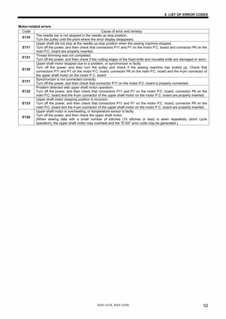
Motor-related errors Code Cause of error and remedy
E110 The needle bar is not stopped in the needle up stop position. Turn the pulley until the point where the error display disappears.
E111 Upper shaft did not stop at the needle up stop position when the sewing machine stopped. Turn off the power, and then check that connectors P11 and P1 on the motor P.C. board and connector P6 on the main P.C. board are properly inserted.
E121 Thread trimming was not completed. Turn off the power, and then check if the cutting edges of the fixed knife and movable knife are damaged or worn.
E130 Upper shaft motor stopped due to a problem, or synchronizer is faulty. Turn off the power, and then turn the pulley and check if the sewing machine has locked up. Check that connectors P11 and P1 on the motor P.C. board, connector P6 on the main P.C. board and the 4-pin connector of the upper shaft motor on the motor P.C. board
E131 Synchronizer is not connected correctly. Turn off the power, and then check that connector P11 on the motor P.C. board is properly connected.
E132 Problem detected with upper shaft motor operation. Turn off the power, and then check that connectors P11 and P1 on the motor P.C. board, connector P6 on the main P.C. board and the 4-pin connector of the upper shaft motor on the motor P.C. board are properly inserted.
E133 Upper shaft motor stopping position is incorrect. Turn off the power, and then check that connectors P11 and P1 on the motor P.C. board, connector P6 on the main P.C. board and the 4-pin connector of the upper shaft motor on the motor P.C. board are properly inserted.
E150 Upper shaft motor is overheating, or temperature sensor is faulty. Turn off the power, and then check the upper shaft motor. (When sewing data with a small number of stitches (15 stitches or less) is sewn repeatedly (short cycle operation), the upper shaft motor may overheat and the “E150” error code may be generated.)
8. LIST OF ERROR CODES
BAS-341H, BAS-342H53
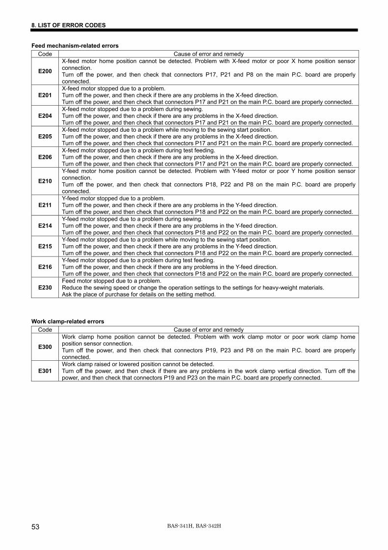
Feed mechanism-related errors Code Cause of error and remedy
E200 X-feed motor home position cannot be detected. Problem with X-feed motor or poor X home position sensor connection. Turn off the power, and then check that connectors P17, P21 and P8 on the main P.C. board are properly connected.
E201 X-feed motor stopped due to a problem. Turn off the power, and then check if there are any problems in the X-feed direction. Turn off the power, and then check that connectors P17 and P21 on the main P.C. board are properly connected.
E204 X-feed motor stopped due to a problem during sewing. Turn off the power, and then check if there are any problems in the X-feed direction. Turn off the power, and then check that connectors P17 and P21 on the main P.C. board are properly connected.
E205 X-feed motor stopped due to a problem while moving to the sewing start position. Turn off the power, and then check if there are any problems in the X-feed direction. Turn off the power, and then check that connectors P17 and P21 on the main P.C. board are properly connected.
E206 X-feed motor stopped due to a problem during test feeding. Turn off the power, and then check if there are any problems in the X-feed direction. Turn off the power, and then check that connectors P17 and P21 on the main P.C. board are properly connected.
E210 Y-feed motor home position cannot be detected. Problem with Y-feed motor or poor Y home position sensor connection. Turn off the power, and then check that connectors P18, P22 and P8 on the main P.C. board are properly connected.
E211 Y-feed motor stopped due to a problem. Turn off the power, and then check if there are any problems in the Y-feed direction. Turn off the power, and then check that connectors P18 and P22 on the main P.C. board are properly connected.
E214 Y-feed motor stopped due to a problem during sewing. Turn off the power, and then check if there are any problems in the Y-feed direction. Turn off the power, and then check that connectors P18 and P22 on the main P.C. board are properly connected.
E215 Y-feed motor stopped due to a problem while moving to the sewing start position. Turn off the power, and then check if there are any problems in the Y-feed direction. Turn off the power, and then check that connectors P18 and P22 on the main P.C. board are properly connected.
E216 Y-feed motor stopped due to a problem during test feeding. Turn off the power, and then check if there are any problems in the Y-feed direction. Turn off the power, and then check that connectors P18 and P22 on the main P.C. board are properly connected.
E230 Feed motor stopped due to a problem. Reduce the sewing speed or change the operation settings to the settings for heavy-weight materials. Ask the place of purchase for details on the setting method.
Work clamp-related errors Code Cause of error and remedy
E300 Work clamp home position cannot be detected. Problem with work clamp motor or poor work clamp home position sensor connection. Turn off the power, and then check that connectors P19, P23 and P8 on the main P.C. board are properly connected.
E301 Work clamp raised or lowered position cannot be detected. Turn off the power, and then check if there are any problems in the work clamp vertical direction. Turn off the power, and then check that connectors P19 and P23 on the main P.C. board are properly connected.
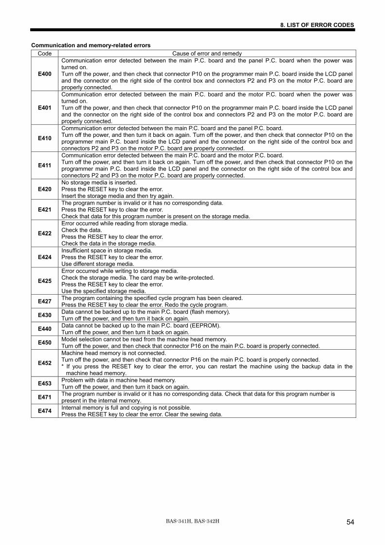
8. LIST OF ERROR CODES
BAS-341H, BAS-342H 54
Communication and memory-related errors Code Cause of error and remedy
E400
Communication error detected between the main P.C. board and the panel P.C. board when the power was turned on. Turn off the power, and then check that connector P10 on the programmer main P.C. board inside the LCD panel and the connector on the right side of the control box and connectors P2 and P3 on the motor P.C. board are properly connected.
E401
Communication error detected between the main P.C. board and the motor P.C. board when the power was turned on. Turn off the power, and then check that connector P10 on the programmer main P.C. board inside the LCD panel and the connector on the right side of the control box and connectors P2 and P3 on the motor P.C. board are properly connected.
E410 Communication error detected between the main P.C. board and the panel P.C. board. Turn off the power, and then turn it back on again. Turn off the power, and then check that connector P10 on the programmer main P.C. board inside the LCD panel and the connector on the right side of the control box and connectors P2 and P3 on the motor P.C. board are properly connected.
E411 Communication error detected between the main P.C. board and the motor P.C. board. Turn off the power, and then turn it back on again. Turn off the power, and then check that connector P10 on the programmer main P.C. board inside the LCD panel and the connector on the right side of the control box and connectors P2 and P3 on the motor P.C. board are properly connected.
E420 No storage media is inserted. Press the RESET key to clear the error. Insert the storage media and then try again.
E421 The program number is invalid or it has no corresponding data. Press the RESET key to clear the error. Check that data for this program number is present on the storage media.
E422 Error occurred while reading from storage media. Check the data. Press the RESET key to clear the error. Check the data in the storage media.
E424 Insufficient space in storage media. Press the RESET key to clear the error. Use different storage media.
E425 Error occurred while writing to storage media. Check the storage media. The card may be write-protected. Press the RESET key to clear the error. Use the specified storage media.
E427 The program containing the specified cycle program has been cleared. Press the RESET key to clear the error. Redo the cycle program.
E430 Data cannot be backed up to the main P.C. board (flash memory). Turn off the power, and then turn it back on again.
E440 Data cannot be backed up to the main P.C. board (EEPROM). Turn off the power, and then turn it back on again.
E450 Model selection cannot be read from the machine head memory. Turn off the power, and then check that connector P16 on the main P.C. board is properly connected.
E452 Machine head memory is not connected. Turn off the power, and then check that connector P16 on the main P.C. board is properly connected. * If you press the RESET key to clear the error, you can restart the machine using the backup data in the
machine head memory.
E453 Problem with data in machine head memory. Turn off the power, and then turn it back on again.
E471 The program number is invalid or it has no corresponding data. Check that data for this program number is present in the internal memory.
E474 Internal memory is full and copying is not possible. Press the RESET key to clear the error. Clear the sewing data.
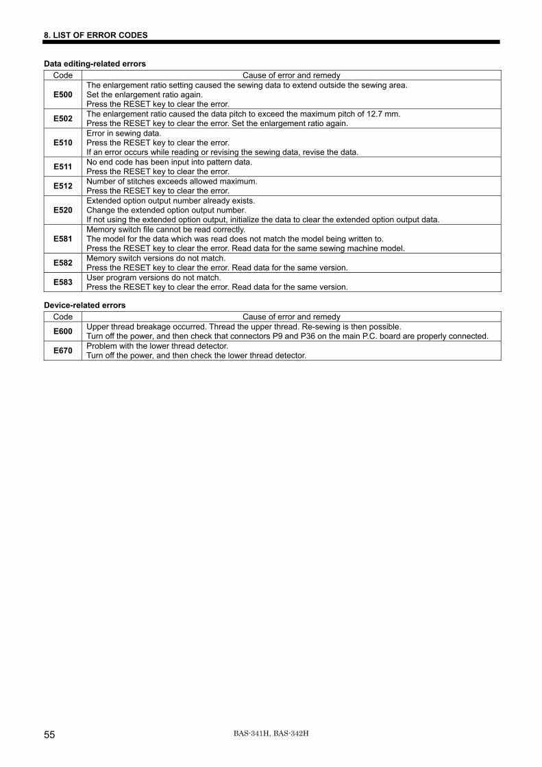
8. LIST OF ERROR CODES
BAS-341H, BAS-342H55
Data editing-related errors Code Cause of error and remedy
E500 The enlargement ratio setting caused the sewing data to extend outside the sewing area. Set the enlargement ratio again. Press the RESET key to clear the error.
E502 The enlargement ratio caused the data pitch to exceed the maximum pitch of 12.7 mm. Press the RESET key to clear the error. Set the enlargement ratio again.
E510 Error in sewing data. Press the RESET key to clear the error. If an error occurs while reading or revising the sewing data, revise the data.
E511 No end code has been input into pattern data. Press the RESET key to clear the error.
E512 Number of stitches exceeds allowed maximum. Press the RESET key to clear the error.
E520 Extended option output number already exists. Change the extended option output number. If not using the extended option output, initialize the data to clear the extended option output data.
E581 Memory switch file cannot be read correctly. The model for the data which was read does not match the model being written to. Press the RESET key to clear the error. Read data for the same sewing machine model.
E582 Memory switch versions do not match. Press the RESET key to clear the error. Read data for the same version.
E583 User program versions do not match. Press the RESET key to clear the error. Read data for the same version.
Device-related errors Code Cause of error and remedy
E600 Upper thread breakage occurred. Thread the upper thread. Re-sewing is then possible. Turn off the power, and then check that connectors P9 and P36 on the main P.C. board are properly connected.
E670 Problem with the lower thread detector. Turn off the power, and then check the lower thread detector.
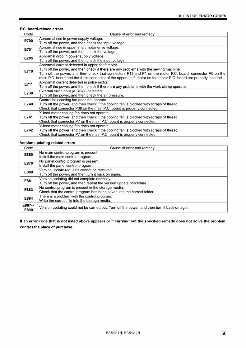
8. LIST OF ERROR CODES
BAS-341H, BAS-342H 56
P.C. board-related errors Code Cause of error and remedy
E700 Abnormal rise in power supply voltage. Turn off the power, and then check the input voltage.
E701 Abnormal rise in upper shaft motor drive voltage. Turn off the power, and then check the voltage.
E705 Abnormal drop in power supply voltage. Turn off the power, and then check the input voltage.
E710 Abnormal current detected in upper shaft motor. Turn off the power, and then check if there are any problems with the sewing machine. Turn off the power, and then check that connectors P11 and P1 on the motor P.C. board, connector P6 on the main P.C. board and the 4-pin connector of the upper shaft motor on the motor P.C. board are properly inserted.
E711 Abnormal current detected in pulse motor. Turn off the power, and then check if there are any problems with the work clamp operation.
E730 External error input (AIRSW) detected. Turn off the power, and then check the air pressure.
E740 Control box cooling fan does not operate. Turn off the power, and then check if the cooling fan is blocked with scraps of thread. Check that connector P38 on the main P.C. board is properly connected.
E741 X-feed motor cooling fan does not operate. Turn off the power, and then check if the cooling fan is blocked with scraps of thread. Check that connector P7 on the main P.C. board is properly connected.
E742 Y-feed motor cooling fan does not operate. Turn off the power, and then check if the cooling fan is blocked with scraps of thread. Check that connector P7 on the main P.C. board is properly connected.
Version updating-related errors Code Cause of error and remedy
E860 No main control program is present. Install the main control program.
E870 No panel control program is present. Install the panel control program.
E880 Version update requests cannot be received. Turn off the power, and then turn it back on again.
E881 Version updating did not complete normally. Turn off the power, and then repeat the version update procedure.
E883 No control program is present in the storage media. Check that the control program has been saved into the correct folder.
E884 There is a problem with the control program. Write the correct file into the storage media.
E887~E890 Version updating could not be carried out. Turn off the power, and then turn it back on again.
If an error code that is not listed above appears or if carrying out the specified remedy does not solve the problem, contact the place of purchase.
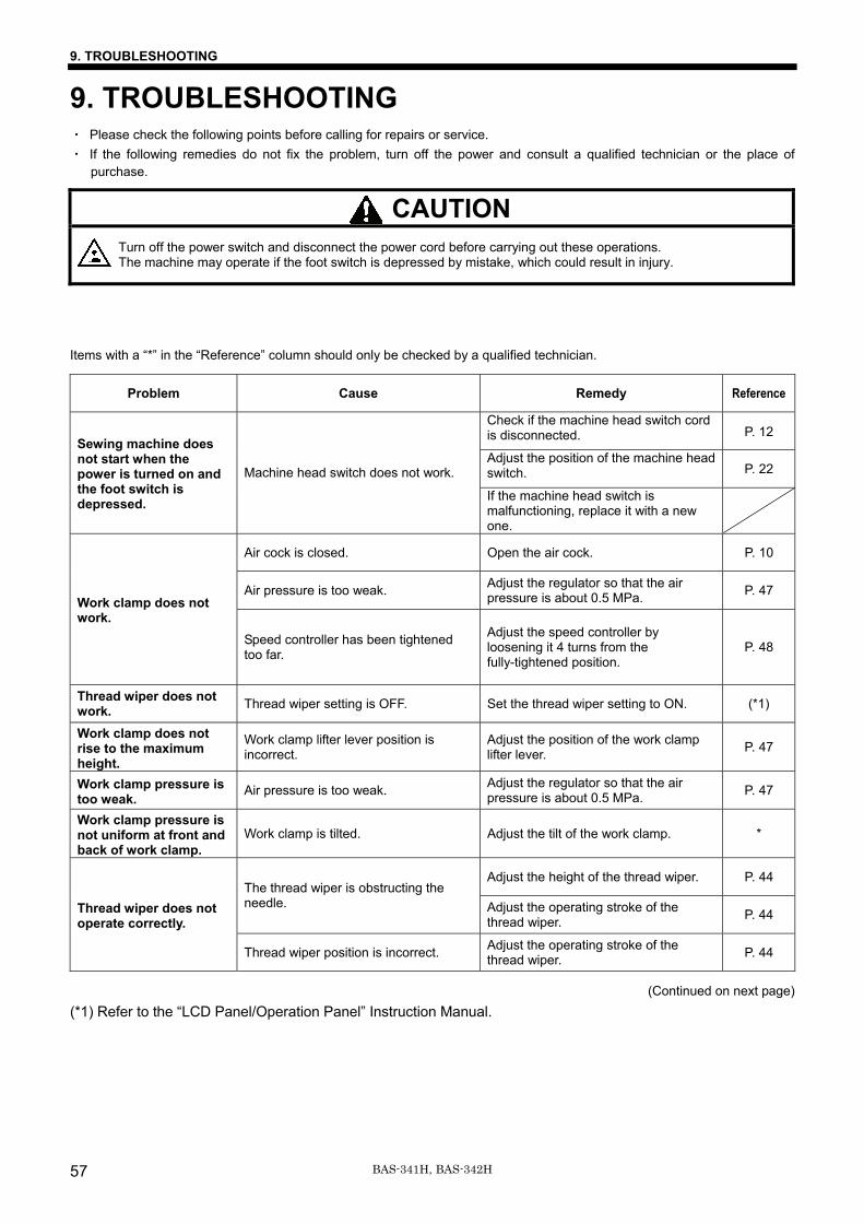
9. TROUBLESHOOTING
BAS-341H, BAS-342H57
9. TROUBLESHOOTING ・ Please check the following points before calling for repairs or service. ・ If the following remedies do not fix the problem, turn off the power and consult a qualified technician or the place of
purchase.
CAUTION Turn off the power switch and disconnect the power cord before carrying out these operations. The machine may operate if the foot switch is depressed by mistake, which could result in injury.
Items with a “*” in the “Reference” column should only be checked by a qualified technician.
Problem Cause Remedy Reference
Check if the machine head switch cord is disconnected. P. 12
Adjust the position of the machine head switch. P. 22
Sewing machine does not start when the power is turned on and the foot switch is depressed.
Machine head switch does not work.
If the machine head switch is malfunctioning, replace it with a new one.
Air cock is closed. Open the air cock. P. 10
Air pressure is too weak. Adjust the regulator so that the air pressure is about 0.5 MPa. P. 47
Work clamp does not work.
Speed controller has been tightened too far.
Adjust the speed controller by loosening it 4 turns from the fully-tightened position.
P. 48
Thread wiper does not work. Thread wiper setting is OFF. Set the thread wiper setting to ON. (*1)
Work clamp does not rise to the maximum height.
Work clamp lifter lever position is incorrect.
Adjust the position of the work clamp lifter lever. P. 47
Work clamp pressure is too weak. Air pressure is too weak. Adjust the regulator so that the air
pressure is about 0.5 MPa. P. 47
Work clamp pressure is not uniform at front and back of work clamp.
Work clamp is tilted. Adjust the tilt of the work clamp. *
Adjust the height of the thread wiper. P. 44 The thread wiper is obstructing the needle. Adjust the operating stroke of the
thread wiper. P. 44 Thread wiper does not operate correctly.
Thread wiper position is incorrect. Adjust the operating stroke of the thread wiper. P. 44
(Continued on next page) (*1) Refer to the “LCD Panel/Operation Panel” Instruction Manual.
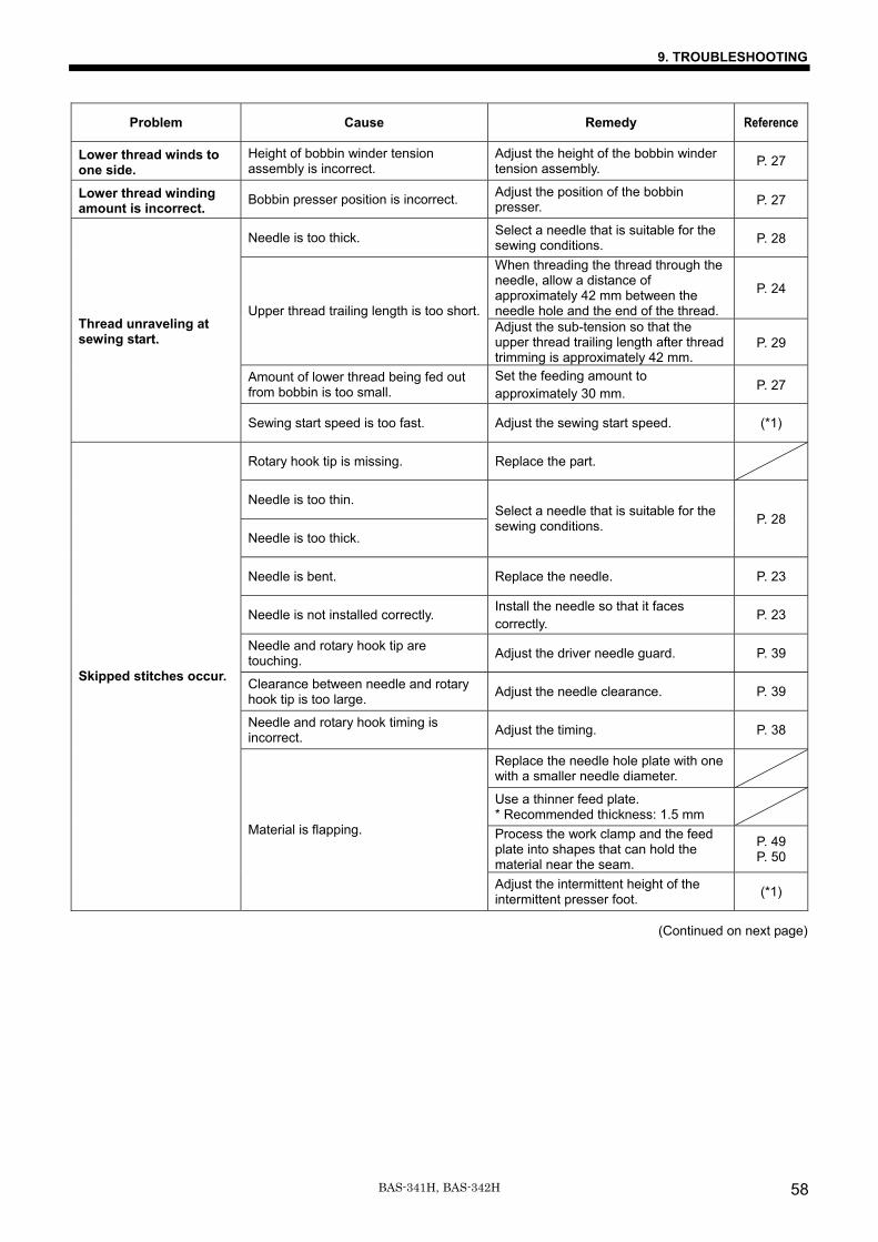
9. TROUBLESHOOTING
BAS-341H, BAS-342H 58
Problem Cause Remedy Reference
Lower thread winds to one side.
Height of bobbin winder tension assembly is incorrect.
Adjust the height of the bobbin winder tension assembly. P. 27
Lower thread winding amount is incorrect. Bobbin presser position is incorrect. Adjust the position of the bobbin
presser. P. 27
Needle is too thick. Select a needle that is suitable for the sewing conditions. P. 28
When threading the thread through the needle, allow a distance of approximately 42 mm between the needle hole and the end of the thread.
P. 24
Upper thread trailing length is too short.Adjust the sub-tension so that the upper thread trailing length after thread trimming is approximately 42 mm.
P. 29
Amount of lower thread being fed out from bobbin is too small.
Set the feeding amount to approximately 30 mm. P. 27
Thread unraveling at sewing start.
Sewing start speed is too fast. Adjust the sewing start speed. (*1)
Rotary hook tip is missing. Replace the part.
Needle is too thin.
Needle is too thick.
Select a needle that is suitable for the sewing conditions. P. 28
Needle is bent. Replace the needle. P. 23
Needle is not installed correctly. Install the needle so that it faces correctly.
P. 23
Needle and rotary hook tip are touching. Adjust the driver needle guard. P. 39
Clearance between needle and rotary hook tip is too large. Adjust the needle clearance. P. 39
Needle and rotary hook timing is incorrect. Adjust the timing. P. 38
Replace the needle hole plate with one with a smaller needle diameter.
Use a thinner feed plate. * Recommended thickness: 1.5 mm
Process the work clamp and the feed plate into shapes that can hold the material near the seam.
P. 49 P. 50
Skipped stitches occur.
Material is flapping.
Adjust the intermittent height of the intermittent presser foot. (*1)
(Continued on next page)
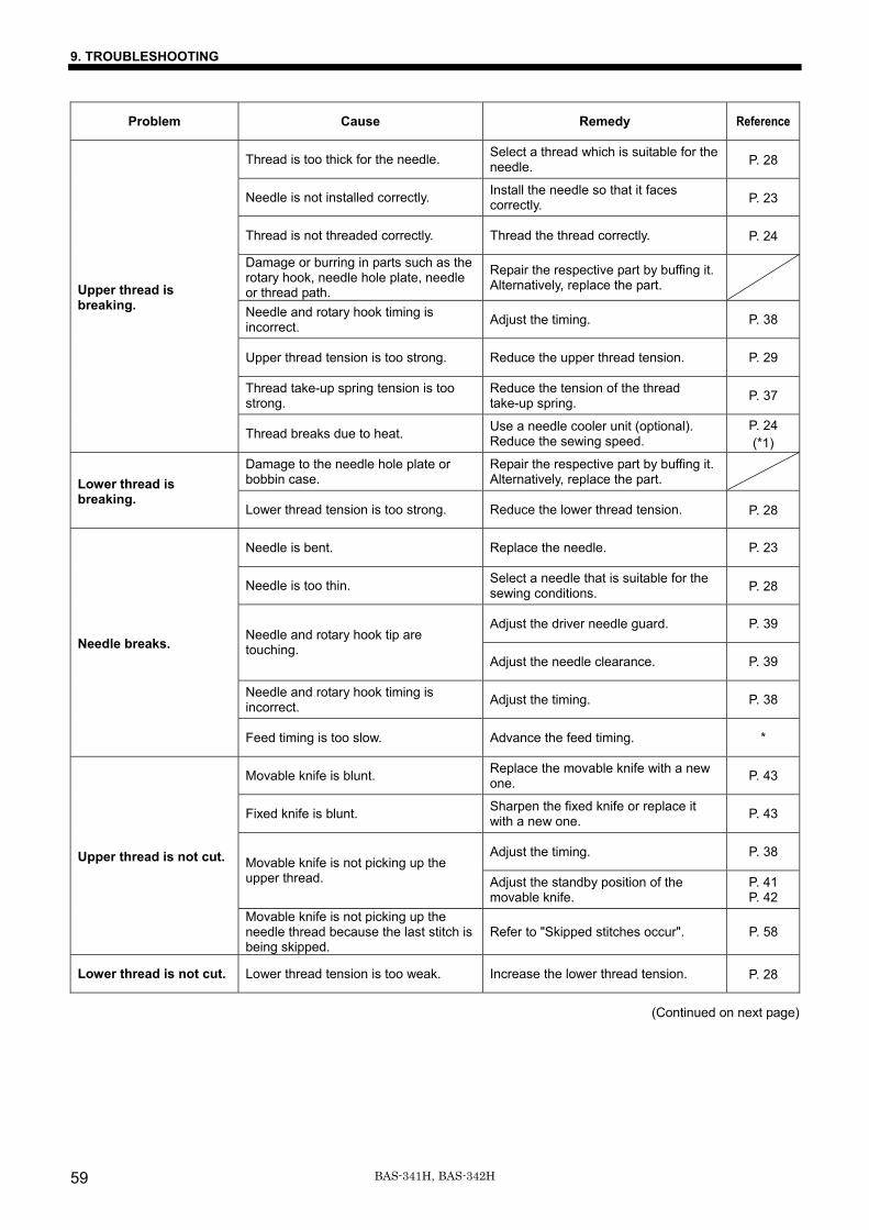
9. TROUBLESHOOTING
BAS-341H, BAS-342H59
Problem Cause Remedy Reference
Thread is too thick for the needle. Select a thread which is suitable for the needle. P. 28
Needle is not installed correctly. Install the needle so that it faces correctly. P. 23
Thread is not threaded correctly. Thread the thread correctly. P. 24
Damage or burring in parts such as the rotary hook, needle hole plate, needle or thread path.
Repair the respective part by buffing it. Alternatively, replace the part.
Needle and rotary hook timing is incorrect. Adjust the timing. P. 38
Upper thread tension is too strong. Reduce the upper thread tension. P. 29
Thread take-up spring tension is too strong.
Reduce the tension of the thread take-up spring. P. 37
Upper thread is breaking.
Thread breaks due to heat. Use a needle cooler unit (optional). Reduce the sewing speed.
P. 24 (*1)
Damage to the needle hole plate or bobbin case.
Repair the respective part by buffing it. Alternatively, replace the part.
Lower thread is breaking.
Lower thread tension is too strong. Reduce the lower thread tension. P. 28
Needle is bent. Replace the needle. P. 23
Needle is too thin. Select a needle that is suitable for the sewing conditions. P. 28
Adjust the driver needle guard. P. 39 Needle and rotary hook tip are touching.
Adjust the needle clearance. P. 39
Needle and rotary hook timing is incorrect. Adjust the timing. P. 38
Needle breaks.
Feed timing is too slow. Advance the feed timing. *
Movable knife is blunt. Replace the movable knife with a new one. P. 43
Fixed knife is blunt. Sharpen the fixed knife or replace it with a new one. P. 43
Adjust the timing. P. 38 Movable knife is not picking up the upper thread. Adjust the standby position of the
movable knife. P. 41 P. 42
Upper thread is not cut.
Movable knife is not picking up the needle thread because the last stitch is being skipped.
Refer to "Skipped stitches occur". P. 58
Lower thread is not cut. Lower thread tension is too weak. Increase the lower thread tension. P. 28
(Continued on next page)
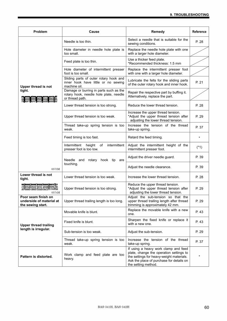
9. TROUBLESHOOTING
BAS-341H, BAS-342H 60
Problem Cause Remedy Reference
Needle is too thin. Select a needle that is suitable for the sewing conditions. P. 28
Hole diameter in needle hole plate is too small.
Replace the needle hole plate with one with a larger hole diameter.
Feed plate is too thin. Use a thicker feed plate. *Recommended thickness: 1.5 mm
Hole diameter of intermittent presser foot is too small.
Replace the intermittent presser foot with one with a larger hole diameter.
Sliding parts of outer rotary hook and inner hook have little or no sewing machine oil.
Lubricate the felts for the sliding parts of the outer rotary hook and inner hook. P. 21
Damage or burring in parts such as the rotary hook, needle hole plate, needle or thread path.
Repair the respective part by buffing it. Alternatively, replace the part.
Lower thread tension is too strong. Reduce the lower thread tension. P. 28
Upper thread tension is too weak. Increase the upper thread tension. *Adjust the upper thread tension after
adjusting the lower thread tension. P. 29
Thread take-up spring tension is too weak.
Increase the tension of the thread take-up spring. P. 37
Feed timing is too fast. Retard the feed timing. *
Intermittent height of intermittent presser foot is too low.
Adjust the intermittent height of the intermittent presser foot. (*1)
Adjust the driver needle guard. P. 39
Upper thread is not tight.
Needle and rotary hook tip are touching.
Adjust the needle clearance. P. 39
Lower thread tension is too weak. Increase the lower thread tension. P. 28 Lower thread is not tight.
Upper thread tension is too strong. Reduce the upper thread tension. *Adjust the upper thread tension after adjusting the lower thread tension.
P. 29
Poor seam finish on underside of material at the sewing start.
Upper thread trailing length is too long.Adjust the sub-tension so that the upper thread trailing length after thread trimming is approximately 42 mm.
P. 29
Movable knife is blunt. Replace the movable knife with a new one. P. 43
Fixed knife is blunt. Sharpen the fixed knife or replace it with a new one. P. 43
Sub-tension is too weak. Adjust the sub-tension. P. 29
Upper thread trailing length is irregular.
Thread take-up spring tension is too weak.
Increase the tension of the thread take-up spring. P. 37
Pattern is distorted. Work clamp and feed plate are too heavy.
If using a heavy work clamp and feed plate, change the operation settings to the settings for heavy-weight materials. Ask the place of purchase for details on the setting method.
*
0574M
0573M
INSTRUCTION MANUAL
© 2015 Brother Industries, Ltd. All Rights Reserved. This is the original instructions.
BAS-341H, BAS-342HI5081061B E2015.09. B (1)
* Please note that the contents of this manual may differ slightly from the actual product purchased as a result of product improvements.