basic shoremaster kit dock instruction
TRANSCRIPT

ShoreMaster Kit Dock Basic Assembly Instructions
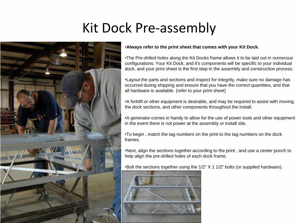
Kit Dock Pre-assembly•Always refer to the print sheet that comes with your Kit Dock.
•The Pre-drilled holes along the Kit Docks frame allows it to be laid out in numerous
configurations. Your Kit Dock, and it's components will be specific to your individual
dock, and your print sheet is the first step in the assembly and construction process.
•Layout the parts and sections and inspect for integrity, make sure no damage has
occurred during shipping and ensure that you have the correct quantities, and that
all hardware is available. (refer to your print sheet)
•A forklift or other equipment is desirable, and may be required to assist with moving
the dock sections, and other components throughout the install.
•A generator comes in handy to allow for the use of power tools and other equipment
in the event there is not power at the assembly or install site.
•To begin , match the tag numbers on the print to the tag numbers on the dock
frames.
•Next, align the sections together according to the print , and use a center punch to
help align the pre-drilled holes of each dock frame.
•Bolt the sections together using the 1/2" X 1 1/2" bolts (or supplied hardware).
Kit Dock Pre-assembly
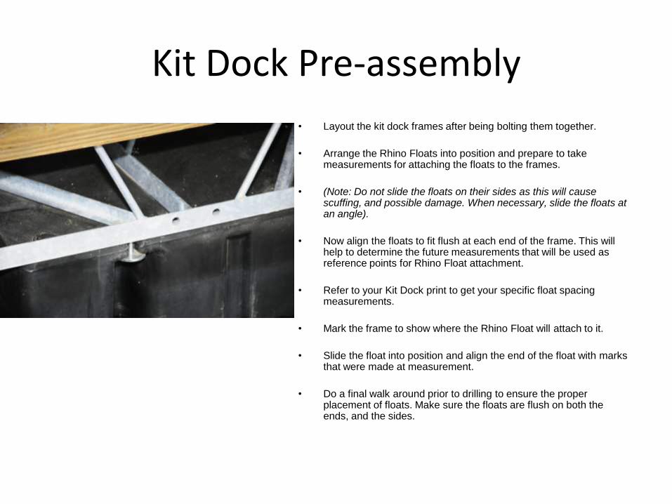
• Layout the kit dock frames after being bolting them together.
• Arrange the Rhino Floats into position and prepare to take measurements for attaching the floats to the frames.
• (Note: Do not slide the floats on their sides as this will cause scuffing, and possible damage. When necessary, slide the floats at an angle).
• Now align the floats to fit flush at each end of the frame. This will help to determine the future measurements that will be used as reference points for Rhino Float attachment.
• Refer to your Kit Dock print to get your specific float spacing measurements.
• Mark the frame to show where the Rhino Float will attach to it.
• Slide the float into position and align the end of the float with marks that were made at measurement.
• Do a final walk around prior to drilling to ensure the proper placement of floats. Make sure the floats are flush on both the ends, and the sides.
Kit Dock Pre-assembly
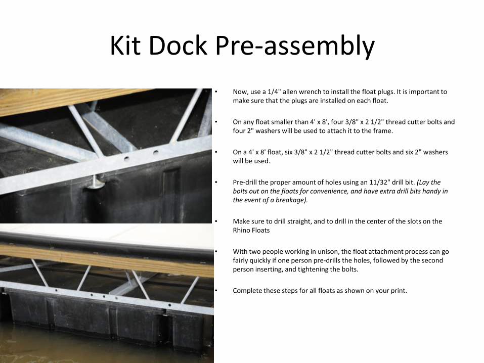
• Now, use a 1/4" allen wrench to install the float plugs. It is important to make sure that the plugs are installed on each float.
• On any float smaller than 4' x 8', four 3/8" x 2 1/2" thread cutter bolts and four 2" washers will be used to attach it to the frame.
• On a 4' x 8' float, six 3/8" x 2 1/2" thread cutter bolts and six 2" washers will be used.
• Pre-drill the proper amount of holes using an 11/32" drill bit. (Lay the bolts out on the floats for convenience, and have extra drill bits handy in the event of a breakage).
• Make sure to drill straight, and to drill in the center of the slots on the Rhino Floats
• With two people working in unison, the float attachment process can go fairly quickly if one person pre-drills the holes, followed by the second person inserting, and tightening the bolts.
• Complete these steps for all floats as shown on your print.

Kit Dock Pre-assembly
• Now attach the rub rail according to your print.
• Mark out the locations of the roofing columns according to your print.
• Measure and cut the rub rail as shown.
• Square off one end board, line the squared end on the line marked earlier, and mark the other end of the board (the beginning of the next column location) with the straight edge.
• Cut board.
• Note: the rub rail could now be attached or you could measure out the rest of the rub rail prior to attaching them.
• A 9/32" drill bit is used to pre-drill the rub rail and dock frame.
• 5/16" x 2 1/2" Torx flat head self tapping screws are used to attach the rub rail to the frame side.
• Rub rail should be 1 1/2" higher than the surface of the finger or dock section. Line up the ends to the marked lines (done earlier). Use a clamp or other tool to hold the rub rail in place.
• (Tip: Use a piece of scrap decking to check the rub rail for a level 1 1/2" height above the surface of the dock frame.)
• Drill hole using the 9/32" drill bit. Put the hole approximately 4" to 6" from the end of the rub rail. Check with a tape measure to ensure 1 1/2" height above the surface of the dock frame.
• Screw in the 5/16" x 2 1/2" Torx flat head self tapping screw. The screw head should be flush, or just below the surface of the rub rail.
• Check the backside of the rub rail to ensure it contacts the outside edge of the dock frame along the length of the rub rail.
• Install all rub rail as shown on your print.

Kit Dock Installation• Always refer to the print sheet that comes with your Kit Dock. The Pre-drilled holes along the Kit Docks frame
allows it to be laid out in numerous configurations. Your Kit Dock, and it's components will be specific to your individual dock, and your print sheet is the first step in the assembly and construction process.
• Layout the parts and sections and inspect for integrity, make sure no damage has occurred during shipping and ensure that you have the correct quantities, and that all hardware is available. (refer to your print sheet)
• A forklift or other equipment is desirable, and may be required to assist with moving the dock sections, and other components throughout the install.
• A generator comes in handy to allow for the use of power tools and other equipment in the event there is not power at the assembly or install site.
• Attach the ramp bracket to the main walk section at the shore side.
• Using a forklift, or by other means, install the finger section(s) into the water. Again, use a rope tied to one end to help position them into place and to allow them to be tied to sure for short periods of time if necessary. A cable should be used if the sections are to be left for longer periods, such as overnight.
• Refer to the print sheet of the dock layout to identify the "Tag" number of each dock section. This tag number will be shown on the print sheet in the same location as it relates to each dock frame or section, and also as it relates to each dock frames position during construction of the Kit Dock.
• Position the main walk section next to the finger section (make sure the tags on the frames are in the same location as shown on your prints).
• Align the pre drilled holes and next insert the proper hardware. Use a center hole punch can be used to help align the holes. Make sure all sections are flush.
• Start on the top of the frame and completely tighten this hardware first. After the top hardware has been completely tightened, the remaining hardware (bottom of the dock frame) can be inserted and tightened.
• Install and position the next finger into place along the main walk section (Left side finger shown). Again use a rope to help guide it into position.
• Then use a center hole punch to help align the pre-drilled . Again insert the hardware on the top of the frame first, and tighten it completely. Then tighten the remaining hardware.
Kit Dock Installation
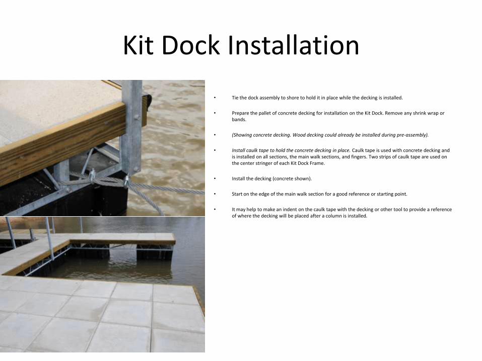
• Tie the dock assembly to shore to hold it in place while the decking is installed.
• Prepare the pallet of concrete decking for installation on the Kit Dock. Remove any shrink wrap or bands.
• (Showing concrete decking. Wood decking could already be installed during pre-assembly).
• Install caulk tape to hold the concrete decking in place. Caulk tape is used with concrete decking and is installed on all sections, the main walk sections, and fingers. Two strips of caulk tape are used on the center stringer of each Kit Dock Frame.
• Install the decking (concrete shown).
• Start on the edge of the main walk section for a good reference or starting point.
• It may help to make an indent on the caulk tape with the decking or other tool to provide a reference of where the decking will be placed after a column is installed.

Kit Dock InstallationStanding The Roofing Columns / Install Purlins
• Standing the column(s) with 2 1/2" x 3 1/2" column bolts. The columns will attach to the kit dock side rail. Tighten.
• It is very important to refer to the prints to find the correct column placement and location.
• The letters on the roofing purlins are placed on the same side of the purlins as the are shown on the print sheet, accordingly they should be laid out or installed the same way.
• Pre-drilled line up holes need to be on the top. They are the small holes.
• Position purlins by weaving in and out of the columns as shown. Then carry the purlins up the ladder (which is tied to the columns for safety and security), and put into position.
• Next use a center hole punch to help align the holes, and insert 1/2" x 3 1/2" column bolt. The bolts should be inserted from the inside with the nut facing outward (the same side as the lower lip of the purlin). This is mostly for appearance and continuity.
• Tighten bolts and nuts just until they begin to dimple the column. Any tighter than that could cause the column to be crushed.

Kit Dock InstallationInstall Roofing Panels
• Follow the procedures for stacking measuring and drilling pattern sheets for the roofing panels.
• Raise the pattern roof sheet into position (this is the top sheet off of the stack, this sheet is the only sheet that has been completely drilled yet, also called the pattern sheet).
• Align the edge of the sheet to the edge of the purlin, and also align the pre-drilled hole to the center hole on the purlin.
• Next double check that the outside edge of the sheet is in alignment with the purlin.
• Mark and drill the remaining roofing panels or sheets according to the pattern sheet that you created earlier.
• Screw the roofing screws through the roof and into the purlins to attach each sheet.
• Next get the roof capping and gable trim ready for installation by peeling off all plastic, and stacking neatly. Inspect each part as you peel it for damages, scratches, etc. Stack as gently as possible to reduce the chance of bending or scratching the trim.
• Lay out the roofing cap, and gable trim.
• Use the supplied roofing screws to attach the gable trim on top and screw the gable trim pieces underneath into the bottom lip of the purlins.
• When inserting screws, it helps to stay in line with the lap screws already installed on the roofing sheets, 2", 1', and 2' for the remainder.
• The gable trim overlaps each other to achieve the desired length.
• Start at the bottom and work your way up, that way the trim pieces will overlap correctly.
• Maneuver the lapped gable trim pieces into position, and secure with roofing screws.
• Try to align the screws that will secure the gable trim pieces with the lapped screws already installed on the roofing sheets. This will give a uniform appearance, and will assist with gable trim screw placement.
• Make sure that the gable trim is as straight and square as possible when viewed from the side.
• Attach the roof ridge cap.
• Line up the roof ridge cap so that it is flush with the edge of the gable trim (to just before the gable trim rolls, or bends downwards.
• Screw in with roofing screws at every other rib
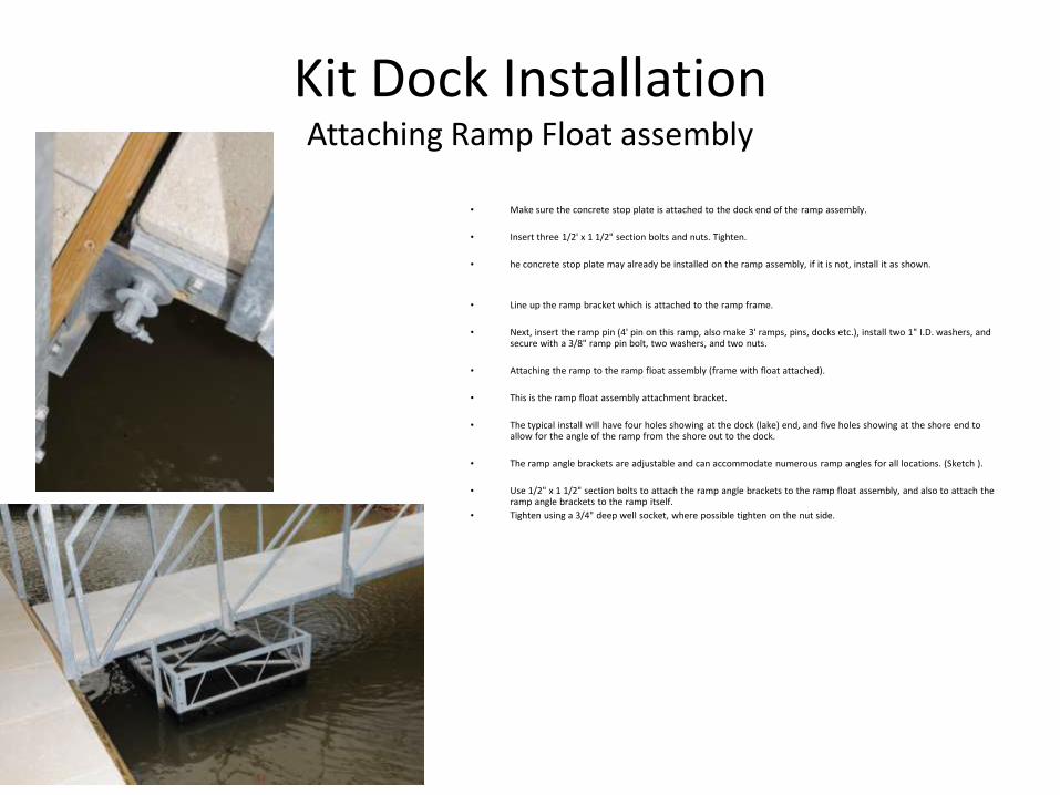
Kit Dock InstallationAttaching Ramp Float assembly
• Make sure the concrete stop plate is attached to the dock end of the ramp assembly.
• Insert three 1/2' x 1 1/2" section bolts and nuts. Tighten.
• he concrete stop plate may already be installed on the ramp assembly, if it is not, install it as shown.
• Line up the ramp bracket which is attached to the ramp frame.
• Next, insert the ramp pin (4' pin on this ramp, also make 3' ramps, pins, docks etc.), install two 1" I.D. washers, and secure with a 3/8" ramp pin bolt, two washers, and two nuts.
• Attaching the ramp to the ramp float assembly (frame with float attached).
• This is the ramp float assembly attachment bracket.
• The typical install will have four holes showing at the dock (lake) end, and five holes showing at the shore end to allow for the angle of the ramp from the shore out to the dock.
• The ramp angle brackets are adjustable and can accommodate numerous ramp angles for all locations. (Sketch ).
• Use 1/2" x 1 1/2" section bolts to attach the ramp angle brackets to the ramp float assembly, and also to attach the ramp angle brackets to the ramp itself.
• Tighten using a 3/4" deep well socket, where possible tighten on the nut side.

Kit Dock InstallationAttaching Ramp
• Position ramp frame in place to make it easy to slide the ramp bracket ears into the angle pieces on the ramp frame.
• nsert the ramp hinge pin through the holes on the ramp attachment bracket after the holes are aligned properly.
• It may help to move or shimmy the ramp, and or the dock assembly until a proper hole alignment is achieved.
• Once the holes are aligned, pound the hinge pin in with a sledge hammer to help get the pin through the holes.
• Place the 1" I.D. washer over the hinge pin end, and secure with a hinge pin bolt, two washers, and two nuts.

Kit Dock InstallationAttaching Anchor Cables,etc.
• Next, wrap the anchor cable around the anchor tube and secure with three 5/8" cable clamps.
• Leave approximately 6" to 8" between the clamps.
• Leave approximately 3' of cable after the last clamp, and wrap the cable around itself. Leaving three feet of cable will allow for any future adjustment to the anchor cable.
• repeat this process on the other side, or on the other anchor cable.
• Now the cables will be attached to shore using a wall mount anchor bracket system, a pour in pier to ramp bracket, or a bolt on pier to ramp bracket.
• Refer to your print and run the cable from the dock (at the cable anchor tube) back to shore (see prints).
• Next run the cable in an angle outward on each side of the ramp frame.
• The distance from the center line of the ramp frame out to the cable anchor system should be the same length as the ramp frame itself.
• For example; if the ramp frame is 28', the cable anchors should be spaced approximately 28' from either side of the center line of the ramp frame.
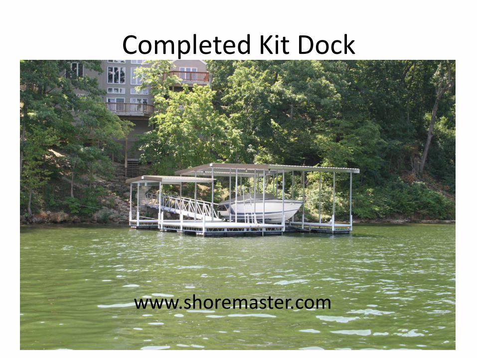
Completed Kit Dock
www.shoremaster.com