bc4 internal bearing rodless cylinder · 2017-10-06 · bc4_2 1.800.328.2174 bc4 band cylinder...
TRANSCRIPT
www.tolomatic.com BC4_1
BC4 INTERNAL BEARING RODLESS CYLINDER
CONTENTSFeatures . . . . . . . . . . . . . . . . . . . . . . . . BC4_2
Performance . . . . . . . . . . . . . . . . . . . . BC4_4
BC406 . . . . . . . . . . . . . . . . . . . . . . . . . . BC4_6
BC410 . . . . . . . . . . . . . . . . . . . . . . . . . . BC4_8
BC412 . . . . . . . . . . . . . . . . . . . . . . . . .BC4_10
BC415 . . . . . . . . . . . . . . . . . . . . . . . . .BC4_12
Long Carrier . . . . . . . . . . . . . . . . . . . .BC4_14
Auxiliary Carrier . . . . . . . . . . . . . . . .BC4_16
Single End Porting . . . . . . . . . . . . . .BC4_18
Foot Mount . . . . . . . . . . . . . . . . . . . . .BC4_19
Tube Supports . . . . . . . . . . . . . . . . . .BC4_20
Floating Mount . . . . . . . . . . . . . . . . .BC4_21
Switches . . . . . . . . . . . . . . . . . . . . . . .BC4_22
Shock Absorbers . . . . . . . . . . . . . . .BC4_24
Application Data Worksheet . . . . .BC4_26
Selection Guidelines . . . . . . . . . . . .BC4_27
Application Guidelines . . . . . . . . . .BC4_28
Service Parts . . . . . . . . . . . . . . . . . . .BC4_29
Ordering . . . . . . . . . . . . . . . . . . . . . . .BC4_30
BC4_2 1.800.328.2174
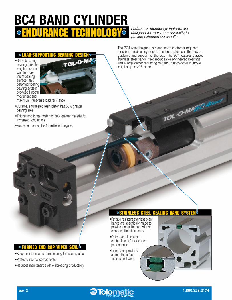
BC4 BAND CYLINDER
STAINLESS STEEL SEALING BAND SYSTEM • Fatigue resistant stainless steel
bands are specifically made to provide longer life and will not elongate, like elastomers
• Outer band keeps out contaminants for extended performance
• Inner band provides a smooth surface for less seal wear
FORMED END CAP WIPER SEAL• Keeps contaminants from entering the sealing area• Protects internal components • Reduces maintenance while increasing productivity
LOAD-SUPPORTING BEARING DESIGN• Self-lubricating
bearing runs the length of carrier web for max-imum bearing surface, this patented floating bearing system provides smooth move ment and maximum transverse load resistance
• Durable, engineered resin piston has 50% greater bearing area
• Thicker and longer web has 60% greater material for increased robustness
• Maximum bearing life for millions of cycles
Endurance Technology features are designed for maximum durability to provide extended service life.
The BC4 was designed in response to customer requests for a basic rodless cylinder for use in applications that have guidance and support for the load. The BC4 features durable stainless steel bands, field replaceable engineered bearings and a large carrier mounting pattern. Built-to-order in stroke lengths up to 206 inches.

www.tolomatic.com BC4_3
AUXILIARY CARRIER• Substantially higher load capacity• Substantially higher bending moment capacity
LONG CARRIER• Substantially higher My and Mz bending
moment capacity• Larger load bearing mounting surface
FLOATING MOUNT• Compensates for non-parallelism between
band cylinder and externally guided load
TUBE SUPPORT MOUNTS• Used for intermediate support
FOOT MOUNTS• For end mounting of band cylinder
SHOCK ABSORBERS• Smooth deceleration, higher productivity• Allows increased operating speed• Self-compensates for load or speed changes• Minimizes impact load to equipment• Adjustable position shocks available
SINGLE END PORTING• Simplifies air connections
SWITCHES• Available in Reed, Hall-effect and Triac • 15ft. cable with flying leads; available with
quick-disconnect couplers
OPTIONS
RIGID CLEAR-ANODIZED EXTRUDED ALUMINUM TUBE
• Stronger, stiffer tube retains tolerance specifications when chamber is pressurized
• Keeps sealing band in place for maximized air efficiency
• Tube supports are minimized • Solid structural support provides
durability and long life performance
ADJUSTABLE CUSHIONS• Adjustable cushions are standard,
not optional• Easy screw adjustment for end-of-
stroke deceleration• Protects actuator and load from
damage
TOLOMATIC … THE RODLESS CYLINDER LEADER
BC4_4 1.800.328.2174
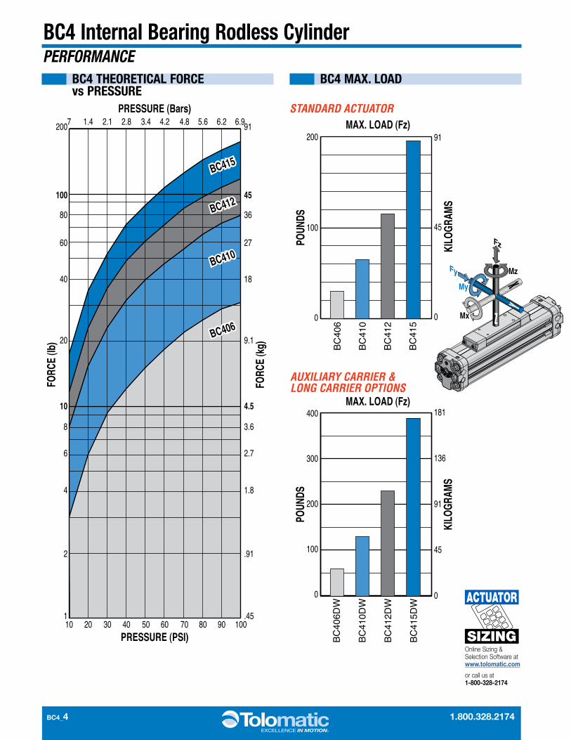
BC4 Internal Bearing Rodless CylinderPERFORMANCE
BC4 MAX. LOADBC4 THEORETICAL FORCE vs PRESSURE
200
100
80
60
40
20
10
8
6
4
2
1
91
45
36
27
18
9.1
4.5
3.6
2.7
1.8
.91
.4510 20 30 40 50 60 70 80 90 100
.7 1.4 2.1 2.8 3.4 4.2 4.8 5.6 6.2 6.9PRESSURE (Bars)
PRESSURE (PSI)
FORC
E (lb
)
FORC
E (k
g)
BC415
BC412
BC410
BC406
BC415
BC412
BC410
BC406
STANDARD ACTUATOR
AUXILIARY CARRIER & LONG CARRIER OPTIONS
BC
406
BC
410
BC
412
BC
415
MAX. LOAD (Fz)
POUN
DS
KILO
GRAM
S
91
45
00
100
200
BC
406D
W
BC
410D
W
BC
412D
W
BC
415D
WMAX. LOAD (Fz)
POUN
DS
KILO
GRAM
S
181
136
91
45
00
200
100
400
300
Online Sizing & Selection Software at www.tolomatic.com
or call us at 1-800-328-2174
SIZING
ACTUATOR
www.tolomatic.com BC4_5
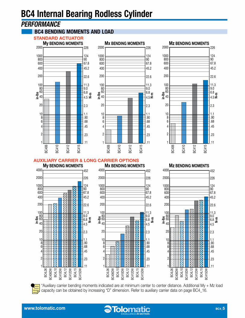
BC4 Internal Bearing Rodless CylinderPERFORMANCE
BC4 BENDING MOMENTS AND LOAD
2000
1000800600400
200
100806040
20
10864
2
1
226
1249067.845.2
22.6
11.39.06.84.5
2.3
1.1.90.68.45
.23
.11
in-lb
s
N-m
in-lb
s
N-m
in-lb
s
N-m
in-lb
s
N-m
in-lb
s
N-m
in-lb
s
N-m
226
1249067.845.2
22.6
11.39.06.84.5
2.3
1.1.90.68.45
.23
.11
BC40
6
BC41
0
BC41
2
BC41
5
BC4L
06
BC40
6DW
BC4L
10
BC41
0DW
BC4L
12
BC41
2DW
BC4L
15
BC41
5DW
BC4L
06
BC40
6DW
BC4L
10
BC41
0DW
BC4L
12
BC41
2DW
BC4L
15
BC41
5DW
BC4L
06
BC40
6DW
BC4L
10
BC41
0DW
BC4L
12
BC41
2DW
BC4L
15
BC41
5DW
2000
1000800600400
200
100806040
20
10864
2
1
BC40
6
BC41
0
BC41
2
BC41
5
My BENDING MOMENTS Mx BENDING MOMENTS226
1249067.845.2
22.6
11.39.06.84.5
2.3
1.1.90.68.45
.23
.11
2000
1000800600400
200
100806040
20
10864
2
1
BC40
6
BC41
0
BC41
2
BC41
5
Mz BENDING MOMENTS
My BENDING MOMENTS Mx BENDING MOMENTS Mz BENDING MOMENTS
2000
1000800600400
4000
200
100806040
20
10864
2
1
226
1249067.845.2
452
22.6
11.39.06.84.5
2.3
1.1.90.68.45
.23
.11
2000
1000800600400
4000
200
100806040
20
10864
2
1
226
1249067.845.2
452
22.6
11.39.06.84.5
2.3
1.1.90.68.45
.23
.11
2000
1000800600400
4000
200
100806040
20
10864
2
1
226
1249067.845.2
452
22.6
11.39.06.84.5
2.3
1.1.90.68.45
.23
.11
STANDARD ACTUATOR
AUXILIARY CARRIER & LONG CARRIER OPTIONS
*Auxiliary carrier bending moments indicated are at minimum center to center distance. Additional My + Mz load capacity can be obtained by increasing “D” dimension. Refer to auxiliary carrier data on page BC4_16.

BC4_6 1.800.328.2174
LOAD (lbs)
FINA
L VE
LOCI
TY (i
n/se
c)
FINA
L VE
LOCI
TY (m
eter
s/se
c)
2.52.3
2.0 1.81.5
1.31.0
.8
.5
.25.23 .20.18 .15.13
.10.08
.05
.03
10090 8070 6050
4030
20
10 98 765
43
2
1
12
34
56
78
910
2030
4050
6070
8090
100
.5
.9
1.4
1.8
2.7
3.2
3.6
4.1
4.5
9.1
13.6
18.1
22.7
27.2
31.7
36.3
40.8
45.4
2.3
LOAD (kg)33
30
27
24
21
18
15
12
9
6
3
0
Max Distance Between Supports (in) “L”
LOAD
WEI
GHT (
lbs)
14.9
13.6
12.2
10.9
9.5
8.2
6.8
5.4
4.1
2.7
1.4
0
LOAD
WEI
GHT (
kg)
0 6 12 18 24 30 4236 48 54 60 66 72
0 304.8
457.2
152.4 609.6
762.0
1066
.891
4.4
1219
.213
71.6
1524
1676
.418
28.8
Max Distance Between Supports (mm) “L”
Maximum Allowable Load
PRESSURE (PSI)
FORC
E (lb
s)
0
2.3
4.5
6.8
9.1
11.3
13.6
15.9
5
10
15
20
25
30
35
0
FORC
E (k
g)
.7 1.4
2.1
2.8
3.4
4.2
4.8
5.6
6.2 6.9
PRESSURE (bar)
10 20 30 40 50 60 70 80 90 100
BC406 Internal Bearing Rodless CylinderPERFORMANCE
THEORETICAL FORCE vs PRESSURE
CUSHION DATA
TUBE SUPPORT REQUIREMENTS
BC406
BC406 OPTIONS PageAuxiliary Carrier BC4_16
Floating Mount Bracket BC4_21Foot Mounts BC4_19Long Carrier BC4_14
Shock Absorbers BC4_24Switches BC4_22
Tube Supports BC4_20MORE INFORMATION Page
Application Guidelines BC4_28Cushion Needle Adjustment BC4_28
Ordering BC4_30Selection BC4_27
ORDER CODES
BC406 inch (U.S. Standard)
BC4M06 (metric with taper port)
LL
W

www.tolomatic.com BC4_7
BC406 Internal Bearing Rodless Cylinder
SPECIFICATIONS
DIMENSIONS
BC406 BENDING MOMENTS AND LOAD
ORDER CODE
BORE SIZE
MAX. BENDING MOMENT MAX. LOAD
My Mx Mz Fz
06 0.625 in 35 in-lbs 3.0 in-lbs 5.0 in-lbs 30.0 lbs
M06 16 mm 3.95 N-m 0.34 N-m 0.56 N-m 13.61 kg
BORE SIZEWEIGHT MAX. STROKE
LENGTH*MAX.
PRESSURETEMPERATURE
RANGEBASE PER UNIT OF STOKE
06 0.625 in 0.68 lb 0.063 lb/in 206 in 100 PSI 20° to 140° F
M06 16 mm 0.31 kg 0.028 kg/mm 5232 mm 6.895 bar -7° to 60° C
*For longer strokes, alternate materials, mounting and/or fasteners – consult Tolomatic
1.250[31.75mm]
.558[14.17mm]
1.180[29.97mm]
3.912[99.36mm]
.590[14.99mm]
.627[15.93mm]
#6-32 X .22 DP (4)[M3x0.5 X 6mm DP]
STROKE + 6.286[159.66mm]
#10-32 X .25 DP[M5X0.8 X 6mm DP]
OPP SIDE OF HEADSHOWN BELOW
#10-32 X .25 DP[M5X0.8 X 6mm DP]
.300[7.62mm]
.473[12.01mm]
.137[3.48mm]
.380[9.65mm]
.873[22.17mm]
.380[9.65mm]
#10-32 X .25 DP[M5x0.8 X 6mm DP]
.750[19.05mm]
.375[9.52mm]
.313[7.95mm]
3.143[79.83mm] STROKE
3.143[79.83mm]
1.741[44.22mm]
1.350[34.29mm]
.695[17.65mm]
.500[12.70mm]
.625[15.87mm]
.290[7.37mm]
.205[5.21mm]
.383[9.73mm]
1.080[27.43mm]
1.171[29.74mm]
.540[13.72mm]
#10-32 X .25 DP[M5x0.8 X 6mm DP]
.750[19.05mm]CENTERED
1.000[25.40mm] .583
[14.81mm]
.128[3.25mm].31
[7.9mm]
.31[7.9mm]
#6-32 X .25 DP (4)[M3X0.5 X 6mm DP]
.11[2.8mm]
6-32 Thru[M3 x .5 Thru]
OPTIONAL NUT
Dimensions in inches [brackets indicate dimensions in millimeters]
3D CAD AVAILABLE AT WWW.TOLOMATIC.COM
BC4_8 1.800.328.2174
LOAD (lbs)
FINA
L VE
LOCI
TY (i
n/se
c)
LOAD (kg)
FINA
L VE
LOCI
TY (m
eter
s/se
c)
2.52.32.0 1.8
1.51.3
1.0.7
.5
.25.23 .20.18
.15.13
.10.08
.05
.03
10090 8070 6050
4030
20
10 98 765
43
2
1
12
34
56
78
910
2030
4050
6070
8090
100
.5
.9
1.41.8 2.7
3.23.6
4.14.5
9.113
.618
.122
.727
.231
.736
.340
.845
.4
2.3
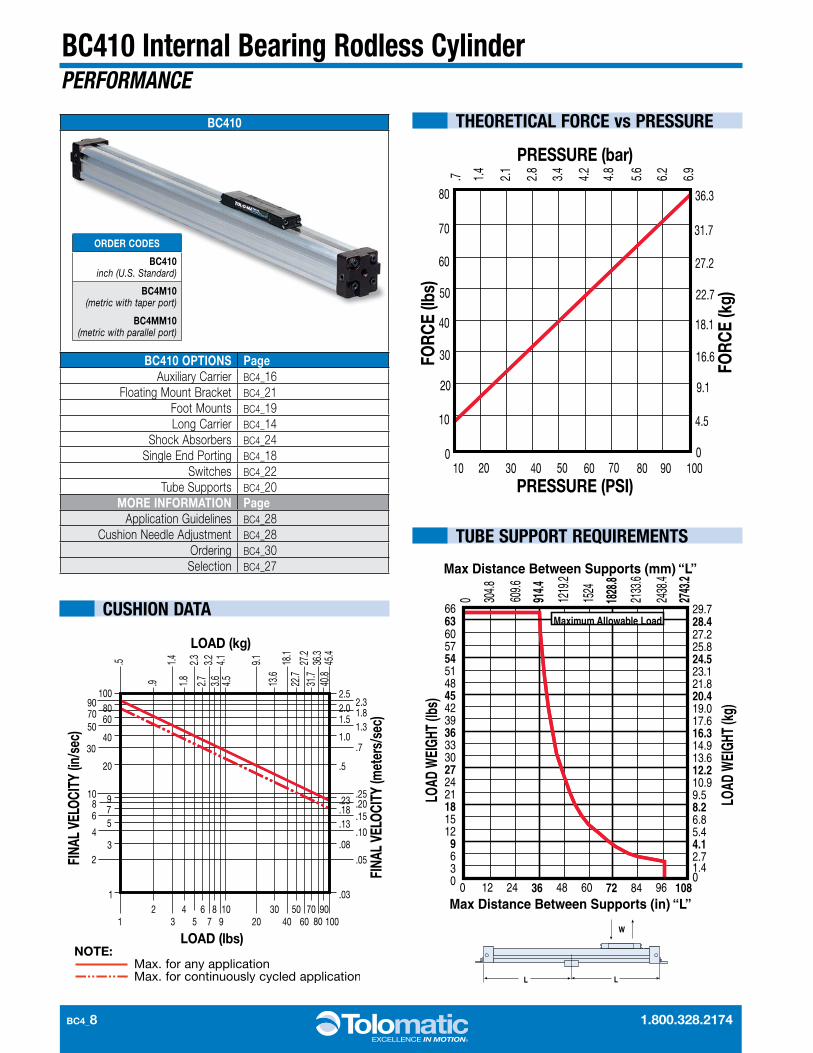
66 6360 57 54 51 48 45 42 39 36 33 30 27 24 21 18 15 12 9630
Max Distance Between Supports (in) “L”
LOAD
WEI
GHT
(lbs)
29.728.427.2 25.8 24.5 23.1 21.8 20.4 19.0 17.6 16.3 14.9 13.6 12.2 10.9 9.5 8.2 6.8 5.4 4.1 2.7 1.4 0
LOAD
WEI
GHT
(kg)
0 12 24 36 48 60 72 84 96 108
0 304.8
609.6
914.4
1219
.2
1524
1828
.8
2133
.6
2438
.4
2743
.2
Max Distance Between Supports (mm) “L”
Maximum Allowable Load
PRESSURE (PSI)
FORC
E (lb
s)0
10
20
30
40
50
60
70
80
0
4.5
9.1
16.6
18.1
22.7
27.2
31.7
36.3
FORC
E (k
g)
.7 1.4
2.1
2.8
3.4
4.2
4.8
5.6
6.2
6.9
PRESSURE (bar)
10 20 30 40 50 60 70 80 90 100
BC410 Internal Bearing Rodless CylinderPERFORMANCE
THEORETICAL FORCE vs PRESSURE
CUSHION DATA
TUBE SUPPORT REQUIREMENTS
LL
W
BC410
BC410 OPTIONS PageAuxiliary Carrier BC4_16
Floating Mount Bracket BC4_21Foot Mounts BC4_19Long Carrier BC4_14
Shock Absorbers BC4_24Single End Porting BC4_18
Switches BC4_22Tube Supports BC4_20
MORE INFORMATION PageApplication Guidelines BC4_28
Cushion Needle Adjustment BC4_28Ordering BC4_30Selection BC4_27
ORDER CODES
BC410 inch (U.S. Standard)
BC4M10 (metric with taper port)
BC4MM10 (metric with parallel port)

www.tolomatic.com BC4_9
BC410 Internal Bearing Rodless CylinderDIMENSIONS
BORE SIZEWEIGHT MAX. STROKE
LENGTH*MAX.
PRESS URETEMPERATURE
RANGEBASE PER UNIT OF STOKE
10 1.00 in 2.36 lbs 0.17 lbs/in 205 in 100 PSI 20° to 140° F
M(MM)10 25 mm 1.07 kg 0.0771 kg/mm 5207 mm 6.895 bar -7° to 60° C
*For longer strokes, alternate materials, mounting and/or fasteners – consult Tolomatic
STROKESTROKE + 7.88 (200.2)
0.90(22.9)
1/8 NPTF [3]
#10-24UNCx .30 DEEP [4]
10-24 UNCx .43
DEEP [4]
2.00 (50.8)1.00
(25.4)0.822
(20.88)0.41(10.4)
1.85(47.0)
0.92(23.4)
2.39(60.7)
2.01(51.1)
1.39(35.3)
0.999(25.4)
3.94 (100.1) 3.94 (100.1)
1.21(30.7)
1.10(27.9)
0.55(14.0)
1.10(27.9)
0.55(14.0)
0.71(18.0)
0.281(7.14)
1.10(27.9)
0.92(23.4)
0.55(14.0)
1/8 NPTF [3]
0.34(8.6)
5.03 (127.8)
0.34(8.6)
END PORTINGOPTIONAL SINGLE
1/8 NPTF [2]
0.23(5.8)
17 (2)1.74 (44.2)
1.76 (44.7)
0.88 (22.4)
1.25(31.8)
0.63(16.0)
0.55(14.0)
1.10(27.9) (M 1/8 BSPT [3])
(MM 1/8 BSPP [3])
(M 1/8 BSPT [3])(MM 1/8 BSPP [3]) (M 1/8 BSPT [3])
(MM 1/8 BSPP [3])
(M5 x 0.8 x 10 DP[4])
(M5 x 0.8 x 6 DP [4])
OT
L - O - M A TI C
0.25(6.4)
OPTIONALNUT FOR SLOTS 0.75
(19.1)
10-24 (M5-0.8) TAPPED HOLE THRU CENTERED ON 0.75 (19.1)
SPECIFICATIONSBC410 BENDING MOMENTS AND LOAD
ORDER CODE
BORE SIZE
MAX. BENDING MOMENT MAX. LOAD
My Mx Mz Fz
10 1.00 in 132 in-lbs 9 in-lbs 27.0 in-lbs 65 lbs
M(MM)10 25 mm 14.91 N-m 1.02 N-m 3.05 N-m 29.48 kg
Dimensions in inches (parenthesis indicate dimensions in millimeters)
3D CAD AVAILABLE AT WWW.TOLOMATIC.COM

BC4_10 1.800.328.2174
12
34
56
78
910
2030
4050
6070
8090100
2001
2
34
56
7 89
10
20
3040
5060 7080 90
100 2.52.3 2.01.8 1.51.3
1.0.8
.5
.3 .23
.20 .18
.15 .13
.10.08
.05
.03
.5
.91.
41.
812.
73.
23.
64.
14.
5
9.1
13.6
18.1
22.7
27.2
31.7
36.3
40.8
45.4
2.3
90.7
LOAD (lbs)
FINA
L VE
LOCI
TY (i
n/se
c)
LOAD (kg)
FINA
L VE
LOCI
TY (m
eter
s/se
c)
120
110
100
90
80
70
60
50
40
30
20
10
00 12 24 36 48 60 72 84 96
Maximum Allowable
Load
Max Distance Between Supports (in) “L”
Max Distance Between Supports (mm) “L”
304.8
609.6
914.4
1219
.2
1524
1828
.8
2133
.6
2438
.4
54.4
49.9
45.4
40.8
36.3
31.7
27.2
22.7
18.1
13.6
9.1
4.5
LOAD
WEI
GHT
(lbs)
LOAD
WEI
GHT
(kg)
10 20 30 40 50 60 70 80 90 1000
25
50
75
100
125
150
175
20090.7
79.4
68.0
56.7
45.4
34.0
22.7
11.3
0
.7 1.4
2.1
2.8
3.4
4.2
4.8
5.6
6.2
6.9
PRESSURE (PSI)
FORC
E (lb
s)
FORC
E (k
g)
PRESSURE (bar)
BC412 Internal Bearing Rodless CylinderPERFORMANCE
THEORETICAL FORCE vs PRESSURE
CUSHION DATA
TUBE SUPPORT REQUIREMENTS
BC412
BC412 OPTIONS PageAuxiliary Carrier BC4_16
Floating Mount Bracket BC4_21Foot Mounts BC4_19Long Carrier BC4_14
Shock Absorbers BC4_24Single End Porting BC4_18
Switches BC4_22Tube Supports BC4_20
MORE INFORMATION PageApplication Guidelines BC4_28
Cushion Needle Adjustment BC4_28Ordering BC4_30Selection BC4_27
ORDER CODES
BC412 inch (U.S. Standard)
BC4M12 (metric with taper port)
BC4MM12 (metric with parallel port)
LL
W
www.tolomatic.com BC4_11
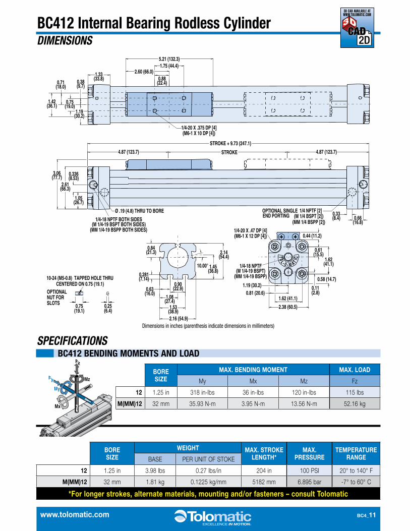
BC412 Internal Bearing Rodless CylinderDIMENSIONS
BORE SIZE
WEIGHT MAX. STROKE LENGTH*
MAX. PRESS URE
TEMPERATURE RANGEBASE PER UNIT OF STOKE
12 1.25 in 3.98 lbs 0.27 lbs/in 204 in 100 PSI 20° to 140° F
M(MM)12 32 mm 1.81 kg 0.1225 kg/mm 5182 mm 6.895 bar -7° to 60° C
*For longer strokes, alternate materials, mounting and/or fasteners – consult Tolomatic
L0T
0 A- M-
TI C
10.00°
2.16 (54.9)
1.08(27.4)
0.63(16.0)
1.53(38.9)
2.14(54.4)
0.84(21.3)
0.281(7.14)
1.45(36.8)
0.90(22.9)
1/4-20 X .375 DP [4](M6-1 X 10 DP [4])
0.75(19.0)
0.38(9.7)
5.21 (132.3)
2.60 (66.0)1.75 (44.4)
0.88(22.4)
1.33(33.8)
1.42(36.1)
0.71(18.0)
1.19(30.2)
4.87 (123.7)
1/4 NPTF [2](M 1/4 BSPT [2])
(MM 1/4 BSPP [2])1/4-18 NPTF BOTH SIDES(M 1/4-19 BSPT BOTH SIDES)
Ø .19 (4.8) THRU TO BORE
STROKE
STROKE + 9.73 (247.1)
4.87 (123.7)
0.33(8.4)
1.05(26.7)
0.336(8.53)
2.61(66.3)
0.66(16.8)
3.06(77.7)
1/4-20 X .47 DP [4](M6-1 X 12 DP [4]) 0.44 (11.2)
0.61(15.5)
1.62(41.1)
0.11(2.8)
0.58 (14.7)
2.38 (60.5)
1.62 (41.1)0.81 (20.6)
1.19 (30.2)
END PORTINGOPTIONAL SINGLE
(MM 1/4-19 BSPP BOTH SIDES)
1/4-18 NPTF(M 1/4-19 BSPT)
(MM 1/4-19 BSPP)
0.25(6.4)
OPTIONALNUT FOR SLOTS 0.75
(19.1)
10-24 (M5-0.8) TAPPED HOLE THRU CENTERED ON 0.75 (19.1)
SPECIFICATIONSBC412 BENDING MOMENTS AND LOAD
ORDER CODE
BORE SIZE
MAX. BENDING MOMENT MAX. LOAD
My Mx Mz Fz
12 1.25 in 318 in-lbs 36 in-lbs 120 in-lbs 115 lbs
M(MM)12 32 mm 35.93 N-m 3.95 N-m 13.56 N-m 52.16 kg
Dimensions in inches (parenthesis indicate dimensions in millimeters)
3D CAD AVAILABLE AT WWW.TOLOMATIC.COM
BC4_12 1.800.328.2174
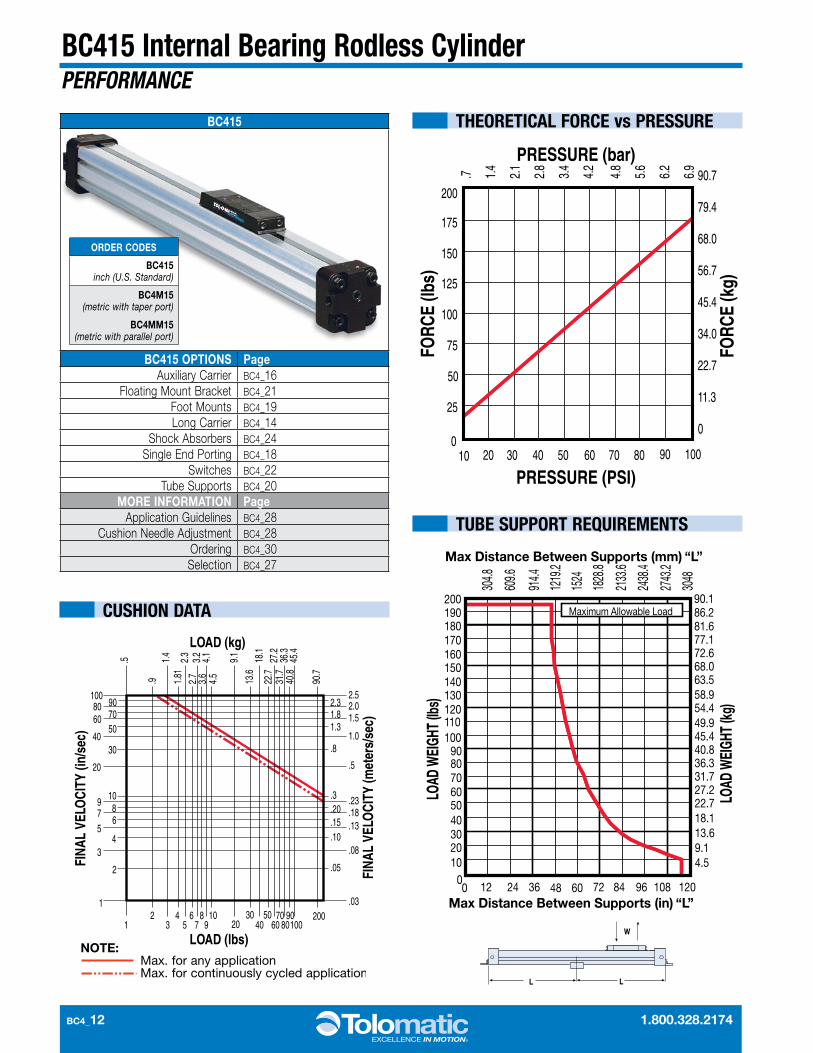
BC415 Internal Bearing Rodless CylinderPERFORMANCE
12
34
56
78
910
2030
4050
6070
8090100
2001
2
34
56
7 89
10
20
3040
5060 7080 90
100 2.52.3 2.01.8 1.51.3
1.0.8
.5
.3 .23
.20 .18
.15 .13
.10.08
.05
.03
.5
.91.
41.
812.
73.
23.
64.
14.
5
9.1
13.6
18.1
22.7
27.2
31.7
36.3
40.8
45.4
2.3
90.7
LOAD (lbs)
FINA
L VE
LOCI
TY (i
n/se
c)
LOAD (kg)
FINA
L VE
LOCI
TY (m
eter
s/se
c)
180190200
170160150140130120110100
908070605040302010
00 12 24 36 48 60 72 84 96 108 120
Maximum Allowable Load
Max Distance Between Supports (in) “L”
Max Distance Between Supports (mm) “L”
304.8
609.6
914.4
1219
.2
1524
1828
.8
2133
.6
2438
.4
2743
.2
3048
90.186.281.6 77.1 72.6 68.0 63.5 58.9 54.4 49.9 45.4 40.8 36.3 31.7 27.2 22.7 18.1 13.6 9.1 4.5
LOAD
WEI
GHT (
lbs)
LOAD
WEI
GHT (
kg)
10 20 30 40 50 60 70 80 90 1000
25
50
75
100
125
150
175
20090.7
79.4
68.0
56.7
45.4
34.0
22.7
11.3
0
.7 1.4
2.1
2.8
3.4
4.2
4.8
5.6
6.2
6.9
PRESSURE (PSI)
FORC
E (lb
s)
FORC
E (k
g)
PRESSURE (bar)
THEORETICAL FORCE vs PRESSURE
CUSHION DATA
TUBE SUPPORT REQUIREMENTS
BC415
BC415 OPTIONS PageAuxiliary Carrier BC4_16
Floating Mount Bracket BC4_21Foot Mounts BC4_19Long Carrier BC4_14
Shock Absorbers BC4_24Single End Porting BC4_18
Switches BC4_22Tube Supports BC4_20
MORE INFORMATION PageApplication Guidelines BC4_28
Cushion Needle Adjustment BC4_28Ordering BC4_30Selection BC4_27
ORDER CODES
BC415 inch (U.S. Standard)
BC4M15 (metric with taper port)
BC4MM15 (metric with parallel port)
LL
W
www.tolomatic.com BC4_13
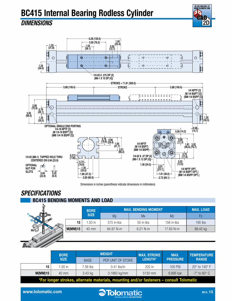
BC415 Internal Bearing Rodless CylinderDIMENSIONS
BORE SIZE
WEIGHT MAX. STROKE LENGTH*
MAX. PRESS URE
TEMPERATURE RANGEBASE PER UNIT OF STOKE
15 1.50 in 7.56 lbs 0.41 lbs/in 202 in 100 PSI 20° to 140° F
M(MM)15 40 mm 3.43 kg 0.1860 kg/mm 5130 mm 6.895 bar -7° to 60° C
*For longer strokes, alternate materials, mounting and/or fasteners – consult Tolomatic
1/4-18 NPTF [3](M 1/4-19 BSPT [3])
(MM 1/4-19 BSPP [3])
(M 1/4 BSPT [3])(MM 1/4 BSPP [3])
1/4 NPTF [3]5.88 (149.4)5.88 (149.4) STROKE
STROKE + 11.81 (300.0)
0.58(14.7)
1.20(30.5)
2.99(75.9)
1.20(30.5)
0.79(20.1)3.56
(90.4)
1.25(31.8)
1.34(34.0)
0.50(12.7)
1.00(25.4)1.50
(38.1)
3.00 (76.2)6.28 (159.5)
1/4-20 X .375 DP [4](M6-1 X 10 DP [4])
2.60 (66.0)1.86 (47.2)
0.74(18.8)
1.30(33.0)
2.61(66.3)
1.64(41.7)
0.78(19.8)
0.313(7.95)
0.96(24.4)
1.81 (46.0)2.72 (69.1)
0.91(23.1)
1.36 (34.5)
1/4 NPTF(M 1/4 BSPT)
(MM 1/4 BSPP)
1/4 NPTF OPT.(M 1/4 BSPT OPT.)
(MM 1/4 BSPP OPT.)
1/4-20 X .47 DP [4](M6-1 X 12 DP [4])
0.56 (14.2)
1.81(46.0)
3.02(76.7)
0.68(17.3)
0.53(13.5)
0.70(17.8)
OPTIONAL SINGLE END PORTING
L0T
0 A- M-
T I C
0.25(6.4)
OPTIONALNUT FOR SLOTS 0.94
(23.9)
1/4-20 (M6-1) TAPPED HOLE THRU CENTERED ON 0.94 (23.9)
SPECIFICATIONSBC415 BENDING MOMENTS AND LOAD
ORDER CODE
BORE SIZE
MAX. BENDING MOMENT MAX. LOAD
My Mx Mz Fz
15 1.50 in 575 in-lbs 55 in-lbs 156 in-lbs 195 lbs
M(MM)15 40 mm 64.97 N-m 6.21 N-m 17.63 N-m 88.45 kg
Dimensions in inches (parenthesis indicate dimensions in millimeters)
3D CAD AVAILABLE AT WWW.TOLOMATIC.COM
BC4_14 1.800.328.2174
ABC D
E (8)
STROKE + FG
BC4 Long Carrier - All Sizes
BC4L(Long Carrier)
BC4(Standard Carrier)
Long Carrier Option
ORDER CODE
L
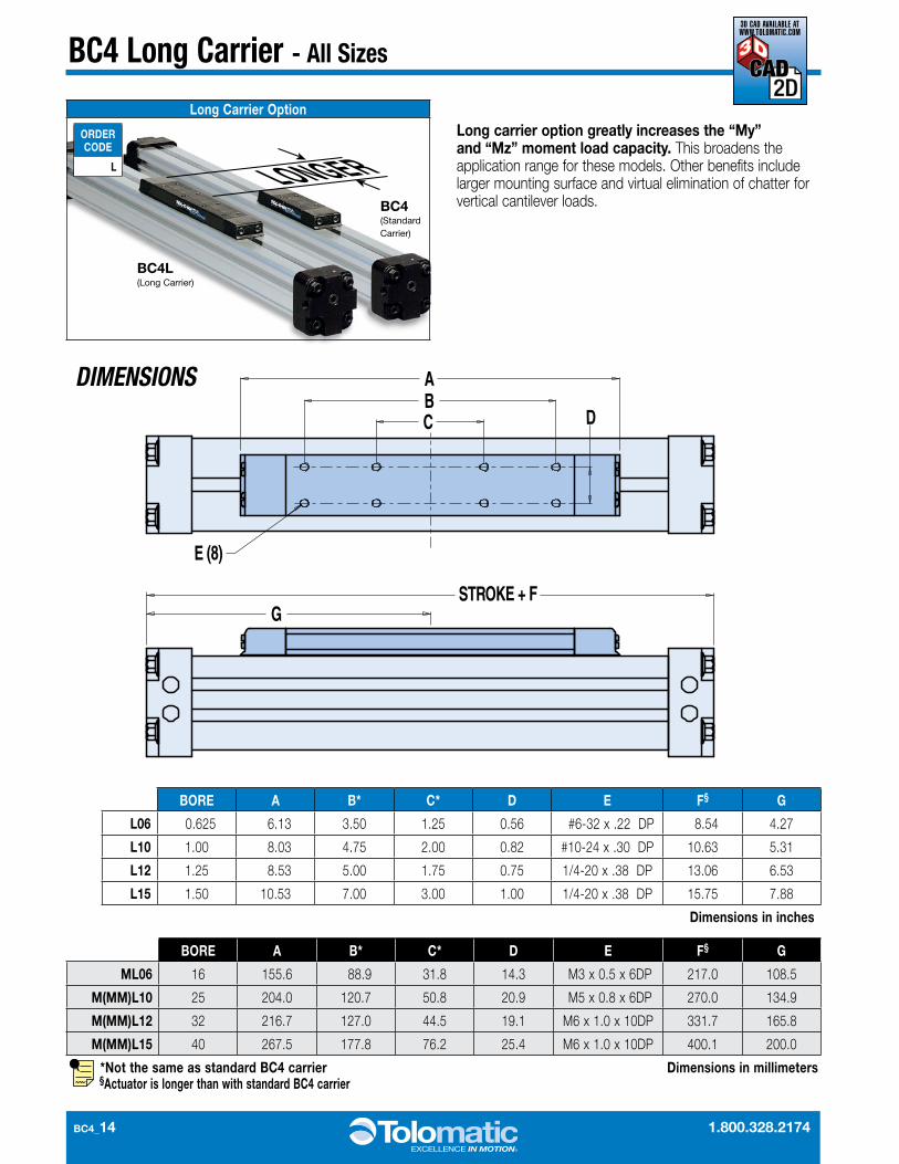
Long carrier option greatly increases the “My” and “Mz” moment load capacity. This broadens the application range for these models. Other benefits include larger mounting surface and virtual elimination of chatter for vertical cantilever loads.
BORE A B* C* D E F§ G
L06 0.625 6.13 3.50 1.25 0.56 #6-32 x .22 DP 8.54 4.27
L10 1.00 8.03 4.75 2.00 0.82 #10-24 x .30 DP 10.63 5.31
L12 1.25 8.53 5.00 1.75 0.75 1/4-20 x .38 DP 13.06 6.53
L15 1.50 10.53 7.00 3.00 1.00 1/4-20 x .38 DP 15.75 7.88
Dimensions in inches
BORE A B* C* D E F§ G
ML06 16 155.6 88.9 31.8 14.3 M3 x 0.5 x 6DP 217.0 108.5
M(MM)L10 25 204.0 120.7 50.8 20.9 M5 x 0.8 x 6DP 270.0 134.9
M(MM)L12 32 216.7 127.0 44.5 19.1 M6 x 1.0 x 10DP 331.7 165.8
M(MM)L15 40 267.5 177.8 76.2 25.4 M6 x 1.0 x 10DP 400.1 200.0
*Not the same as standard BC4 carrier §Actuator is longer than with standard BC4 carrier
Dimensions in millimeters
DIMENSIONS
3D CAD AVAILABLE AT WWW.TOLOMATIC.COM
www.tolomatic.com BC4_15
BC4 Long Carrier - All Sizes
PERFORMANCE
BORE SIZE
MAXIMUM BENDING MOMENT MAX. LOAD
My (Standard) My (Long) Mx† Mz (Standard) Mz (Long) Fz†
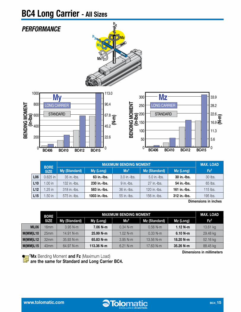
L06 0.625 in 35 in.-lbs. 63 in.-lbs. 3.0 in.-lbs. 5.0 in.-lbs. 30 in.-lbs. 30 lbs.
L10 1.00 in 132 in.-lbs. 230 in.-lbs. 9 in.-lbs. 27 in.-lbs. 54 in.-lbs. 65 lbs.
L12 1.25 in 318 in.-lbs. 583 in.-lbs. 36 in.-lbs. 120 in.-lbs. 161 in.-lbs. 115 lbs.
L15 1.50 in 575 in.-lbs. 1003 in.-lbs. 55 in.-lbs. 156 in.-lbs. 312 in.-lbs. 195 lbs.Dimensions in inches
BORE SIZE
MAXIMUM BENDING MOMENT MAX. LOAD
My (Standard) My (Long) Mx† Mz (Standard) Mz (Long) Fz†
ML06 16mm 3.95 N-m 7.06 N-m 0.34 N-m 0.56 N-m 1.12 N-m 13.61 kg
M(MM)L10 25mm 14.91 N-m 25.99 N-m 1.02 N-m 0.33 N-m 6.10 N-m 29.48 kg
M(MM)L12 32mm 35.93 N-m 65.83 N-m 3.95 N-m 13.56 N-m 18.20 N-m 52.16 kg
M(MM)L15 40mm 64.97 N-m 113.36 N-m 6.21 N-m 17.63 N-m 35.26 N-m 88.45 kg
†Mx Bending Moment and Fz (Maximum Load) are the same for Standard and Long Carrier BC4.
Dimensions in millimeters
0
200
400
600
800
1000
BC406 BC410 BC412 BC415
BC406 BC410 BC412 BC415
0
22.6
45.2
67.8
90.4
113.0
0
50
100
150
200
250
300
0
5.6
11.3
16.9
22.6
28.2
33.9
BEND
ING
MO
MEN
T (in
-lbs)
(N-m
)
BEND
ING
MO
MEN
T (in
-lbs)
(N-m
)
Mz
MyLONG CARRIER
STANDARD
LONG CARRIER
STANDARD
0
200
400
600
800
1000
BC406 BC410 BC412 BC415
BC406 BC410 BC412 BC415
0
22.6
45.2
67.8
90.4
113.0
0
50
100
150
200
250
300
0
5.6
11.3
16.9
22.6
28.2
33.9
BEND
ING
MO
MEN
T (in
-lbs)
(N-m
)
BEND
ING
MO
MEN
T (in
-lbs)
(N-m
)
Mz
MyLONG CARRIER
STANDARD
LONG CARRIER
STANDARD
BC4_16 1.800.328.2174
BC4 Auxiliary Carrier - All Sizes
AUXILIARY CARRIER
ORDER CODE
DW (Auxiliary Carrier with piston)
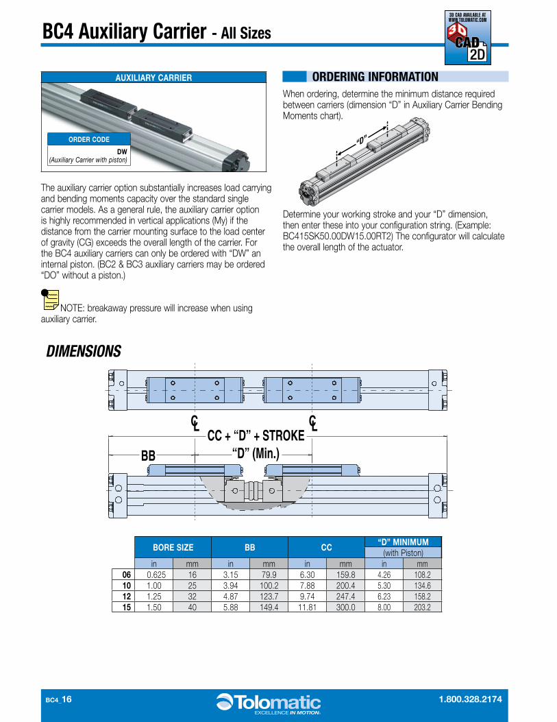
The auxiliary carrier option substantially increases load carrying and bending moments capacity over the standard single carrier models. As a general rule, the auxiliary carrier option is highly recommended in vertical applications (My) if the distance from the carrier mounting surface to the load center of gravity (CG) exceeds the overall length of the carrier. For the BC4 auxiliary carriers can only be ordered with “DW” an internal piston. (BC2 & BC3 auxiliary carriers may be ordered “DO” without a piston.)
NOTE: breakaway pressure will increase when using auxiliary carrier.
When ordering, determine the minimum distance required between carriers (dimension “D” in Auxiliary Carrier Bending Moments chart).
Determine your working stroke and your “D” dimension, then enter these into your configuration string. (Example: BC415SK50.00DW15.00RT2) The configurator will calculate the overall length of the actuator.
ORDERING INFORMATION
BORE SIZE BB CC “D” MINIMUM (with Piston)
in mm in mm in mm in mm06 0.625 16 3.15 79.9 6.30 159.8 4.26 108.210 1.00 25 3.94 100.2 7.88 200.4 5.30 134.612 1.25 32 4.87 123.7 9.74 247.4 6.23 158.215 1.50 40 5.88 149.4 11.81 300.0 8.00 203.2
C
BB “D” (Min.)CC + “D” + STROKE
L CL
DIMENSIONS
3D CAD AVAILABLE AT WWW.TOLOMATIC.COM
www.tolomatic.com BC4_17
BC4 Auxiliary Carrier - All SizesPERFORMANCE
BENDING MOMENTS
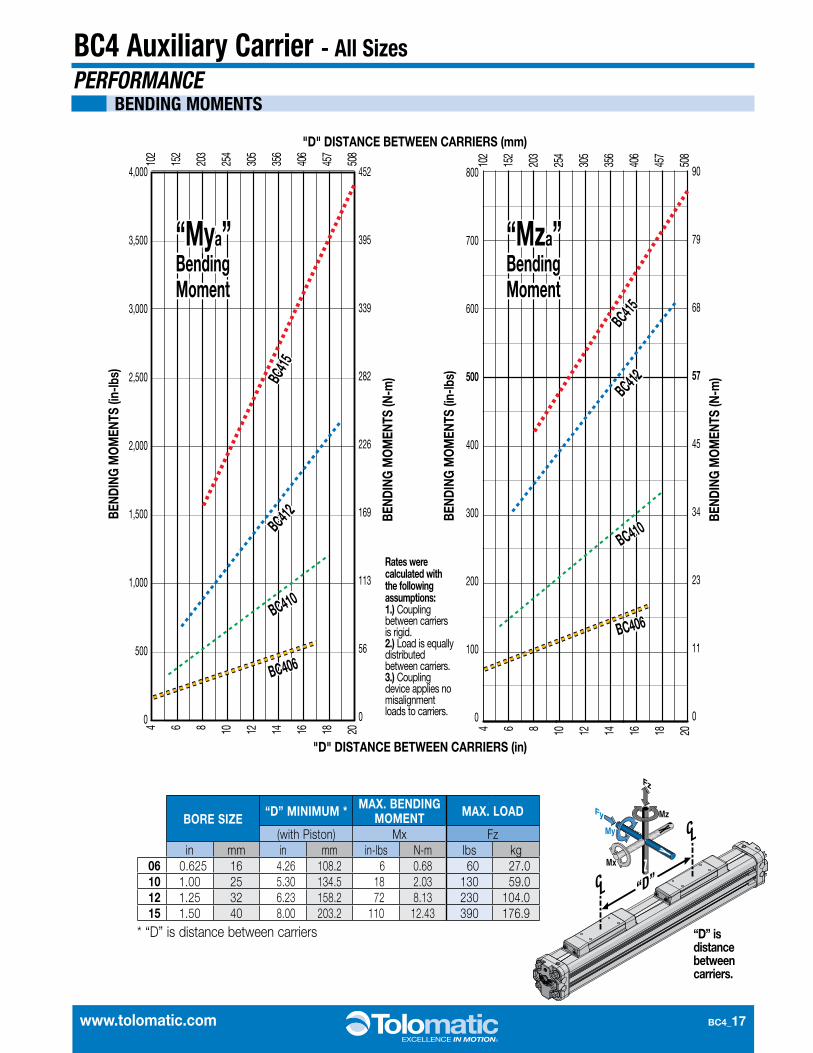
BORE SIZE “D” MINIMUM * MAX. BENDING MOMENT MAX. LOAD
(with Piston) Mx Fzin mm in mm in-lbs N-m lbs kg
06 0.625 16 4.26 108.2 6 0.68 60 27.010 1.00 25 5.30 134.5 18 2.03 130 59.012 1.25 32 6.23 158.2 72 8.13 230 104.015 1.50 40 8.00 203.2 110 12.43 390 176.9
* “D” is distance between carriers
"D" DISTANCE BETWEEN CARRIERS (mm)
"D" DISTANCE BETWEEN CARRIERS (in)
BEND
ING
MO
MEN
TS (i
n-lb
s)
BEND
ING
MO
MEN
TS (N
-m)
BEND
ING
MO
MEN
TS (N
-m)
4 6 8 10 12 14 16 18 20 4 6 8 10 12 14 16 18 20
102
152
203
254
305
356
406
457
508
102
152
203
254
305
356
406
457
508
4,000
3,500
3,000
2,500
2,000
1,500
1,000
500
0
452
395
339
282
226
169
113
56
0
BEND
ING
MO
MEN
TS (i
n-lb
s)
800
700
600
500
400
300
200
100
0
90
79
68
57
45
34
23
11
0
“Mya” Bending Moment
“Mza” Bending Moment
“Mya” Bending Moment
“Mza” Bending Moment
BC415
BC412
BC410
BC406
BC415BC412
BC410
BC406
BC415
BC412
BC410
BC406
BC415BC412
BC410
BC406
Rates were calculated with the following assumptions:1.) Coupling between carriers is rigid. 2.) Load is equally distributed between carriers. 3.) Coupling device applies no misalignment loads to carriers.
“D” is distance between carriers.

BC4_18 1.800.328.2174
BC4 Single End Porting - 10, 12, 15 Sizes
AIR FLOW DIAGRAMS
NOTE: Standard porting may be field converted to ported from left or ported from right. For complete instructions refer to parts sheet.
Single End Porting
ORDER CODE
HD
Main Port
Cross Port Ported From Right Side
PluggedOpen
Pipe Plug inserted
Pipe Plugremoved
Main Port
Cross Port
PISTON
Main Port
Cross Port
Main Port
Cross PortStandard Porting
(cross ports not functional)
Ported From Left Side
Pipe Plugremoved
Pipe Plug inserted
Main Port
Cross Port
Main Port
Cross Port
PISTON
PISTON
SINGLE END PORTING ALLOWS THE GREATEST FLEXIBILITY IN AIR HOOK UP.
This option allows you to run air lines to just one end of the BC4, simplifying air hook up. The Single End Porting option for the BC410 is factory installed on the right side.
Not available for 06 (5/8" bore).
www.tolomatic.com BC4_19
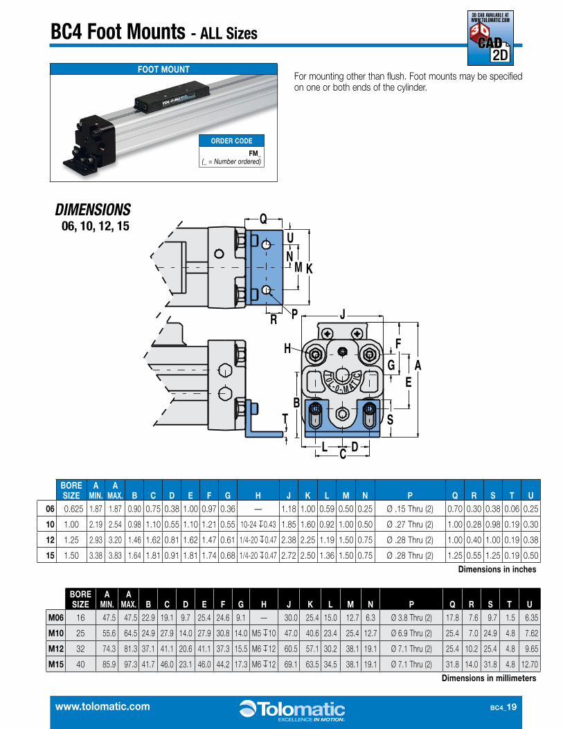
BC4 Foot Mounts - ALL Sizes
DIMENSIONS
For mounting other than flush. Foot mounts may be specified on one or both ends of the cylinder.
BORE SIZE
A MIN.
A MAX. B C D E F G H J K L M N P Q R S T U
06 0.625 1.87 1.87 0.90 0.75 0.38 1.00 0.97 0.36 — 1.18 1.00 0.59 0.50 0.25 Ø .15 Thru (2) 0.70 0.30 0.38 0.06 0.25
10 1.00 2.19 2.54 0.98 1.10 0.55 1.10 1.21 0.55 10-24 0.43 1.85 1.60 0.92 1.00 0.50 Ø .27 Thru (2) 1.00 0.28 0.98 0.19 0.30
12 1.25 2.93 3.20 1.46 1.62 0.81 1.62 1.47 0.61 1/4-20 0.47 2.38 2.25 1.19 1.50 0.75 Ø .28 Thru (2) 1.00 0.40 1.00 0.19 0.38
15 1.50 3.38 3.83 1.64 1.81 0.91 1.81 1.74 0.68 1/4-20 0.47 2.72 2.50 1.36 1.50 0.75 Ø .28 Thru (2) 1.25 0.55 1.25 0.19 0.50
Dimensions in inches
BORE SIZE
A MIN.
A MAX. B C D E F G H J K L M N P Q R S T U
M06 16 47.5 47.5 22.9 19.1 9.7 25.4 24.6 9.1 — 30.0 25.4 15.0 12.7 6.3 Ø 3.8 Thru (2) 17.8 7.6 9.7 1.5 6.35
M10 25 55.6 64.5 24.9 27.9 14.0 27.9 30.8 14.0 M5 10 47.0 40.6 23.4 25.4 12.7 Ø 6.9 Thru (2) 25.4 7.0 24.9 4.8 7.62
M12 32 74.3 81.3 37.1 41.1 20.6 41.1 37.3 15.5 M6 12 60.5 57.1 30.2 38.1 19.1 Ø 7.1 Thru (2) 25.4 10.2 25.4 4.8 9.65
M15 40 85.9 97.3 41.7 46.0 23.1 46.0 44.2 17.3 M6 12 69.1 63.5 34.5 38.1 19.1 Ø 7.1 Thru (2) 31.8 14.0 31.8 4.8 12.70
Dimensions in millimeters
FOOT MOUNT
ORDER CODE
FM_ (_ = Number ordered)
06, 10, 12, 15 H
JC
D
AEG
BS T
F
P
Q
R
KM
NL
L0T
0 A- M-
TI C
UN
M K
P
H
R
Q
L C
J
D
TB
G
S
EA
F
3D CAD AVAILABLE AT WWW.TOLOMATIC.COM
BC4_20 1.800.328.2174
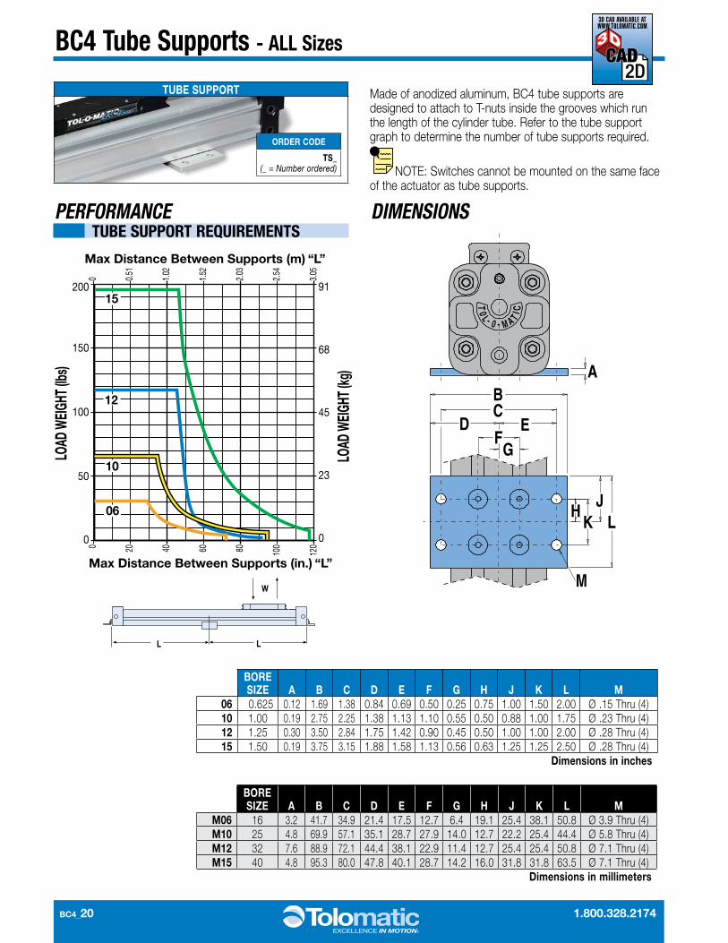
BC4 Tube Supports - ALL Sizes
PERFORMANCE DIMENSIONS
Made of anodized aluminum, BC4 tube supports are designed to attach to T-nuts inside the grooves which run the length of the cylinder tube. Refer to the tube support graph to determine the number of tube supports required.
NOTE: Switches cannot be mounted on the same face of the actuator as tube supports.
BORE SIZE A B C D E F G H J K L M
06 0.625 0.12 1.69 1.38 0.84 0.69 0.50 0.25 0.75 1.00 1.50 2.00 Ø .15 Thru (4)10 1.00 0.19 2.75 2.25 1.38 1.13 1.10 0.55 0.50 0.88 1.00 1.75 Ø .23 Thru (4)12 1.25 0.30 3.50 2.84 1.75 1.42 0.90 0.45 0.50 1.00 1.00 2.00 Ø .28 Thru (4)15 1.50 0.19 3.75 3.15 1.88 1.58 1.13 0.56 0.63 1.25 1.25 2.50 Ø .28 Thru (4)
Dimensions in inches
BORE SIZE A B C D E F G H J K L M
M06 16 3.2 41.7 34.9 21.4 17.5 12.7 6.4 19.1 25.4 38.1 50.8 Ø 3.9 Thru (4)M10 25 4.8 69.9 57.1 35.1 28.7 27.9 14.0 12.7 22.2 25.4 44.4 Ø 5.8 Thru (4)M12 32 7.6 88.9 72.1 44.4 38.1 22.9 11.4 12.7 25.4 25.4 50.8 Ø 7.1 Thru (4)M15 40 4.8 95.3 80.0 47.8 40.1 28.7 14.2 16.0 31.8 31.8 63.5 Ø 7.1 Thru (4)
Dimensions in millimeters
TUBE SUPPORT
ORDER CODE
TS_ (_ = Number ordered)
0
50
100
150
20015
12
10
06
0 20 40 60 80 100
120
0 0.51
1.02
1.52
2.03
2.54
3.05
91
68
45
23
0
Max Distance Between Supports (in.) “L”
Max Distance Between Supports (m) “L”
LOAD
WEI
GHT (
lbs)
LOAD
WEI
GHT (
kg)
TUBE SUPPORT REQUIREMENTSL0
T
0 A- M-
TI C
ABC
D EF
G
JH
K
M
L
LL
W
3D CAD AVAILABLE AT WWW.TOLOMATIC.COM

www.tolomatic.com BC4_21
BC4 Floating Mount Bracket - ALL Sizes
DIMENSIONS
For applications where a BC4 band cylinder is moving a load that is externally guided and supported. An externally guided load, not parallel to the BC4 band cylinder may result in cylinder binding. The floating mount bracket compensates for nonparallelism between the cylinder and the external guide.
(Floating mount brackets are not to be used in conjunction with shock absorbers)
FLOATING MOUNT BRACKET
ORDER CODE
FL
06, 10, 12, 15
F GH
E
AB
DC
MAX. HEIGHT JK
LNM P
øR S
TL0T
0- M A-
T I C
T
SØR
KLN
MP
HGF
EB
C D
A
JMAX. HEIGHT
Please Note: For Dimension “E”BC406 and BC410 use 2 center holesBC412 and BC415 use 4 corner holes
BORE SIZE A B C D E F G H J K L M N P ØR S T
06 0.625 0.90 0.50 0.25 0.45 Ø .17 Thru (2) — 0.63 — 0.33 1.27 0.81 0.18 0.63 0.38 0.25 0.72 2.1810 1.00 1.26 0.63 0.32 0.63 Ø .22 Thru (2) — 0.82 — 0.33 1.64 1.00 0.18 0.82 0.56 0.38 1.01 3.0412 1.25 1.50 0.75 0.37 0.75 Ø .28 Thru (4) 0.50 1.09 1.00 0.44 2.18 1.50 0.41 1.09 0.99 0.44 1.49 4.1015 1.50 1.50 0.75 0.38 0.75 Ø .28 Thru (4) 0.63 1.24 1.25 0.52 2.48 1.63 0.39 1.24 0.99 0.44 1.56 4.62
Dimensions in inches
BORE SIZE A B C D E F G H J K L M N P ØR S T
M06 16 22.9 12.7 6.4 11.5 Ø 4.3 Thru (2) — 16.1 — 8.3 32.2 20.7 4.6 16.0 9.7 6.4 18.3 55.4M10 25 32.0 16.0 8.0 16.0 Ø 5.3 Thru (2) — 20.8 — 8.3 41.7 25.4 4.6 20.8 14.2 9.7 25.7 77.2M12 32 38.1 19.0 9.4 19.0 Ø 7.1 Thru (4) 12.7 27.7 25.4 11.2 55.4 38.1 10.4 27.7 25.1 11.2 37.8 104.1M15 40 38.1 19.0 9.7 19.0 Ø 7.1 Thru (4) 16.0 31.5 31.8 13.2 63.0 41.4 9.9 31.5 25.1 11.2 39.6 117.3
Dimensions in millimeters
3D CAD AVAILABLE AT WWW.TOLOMATIC.COM
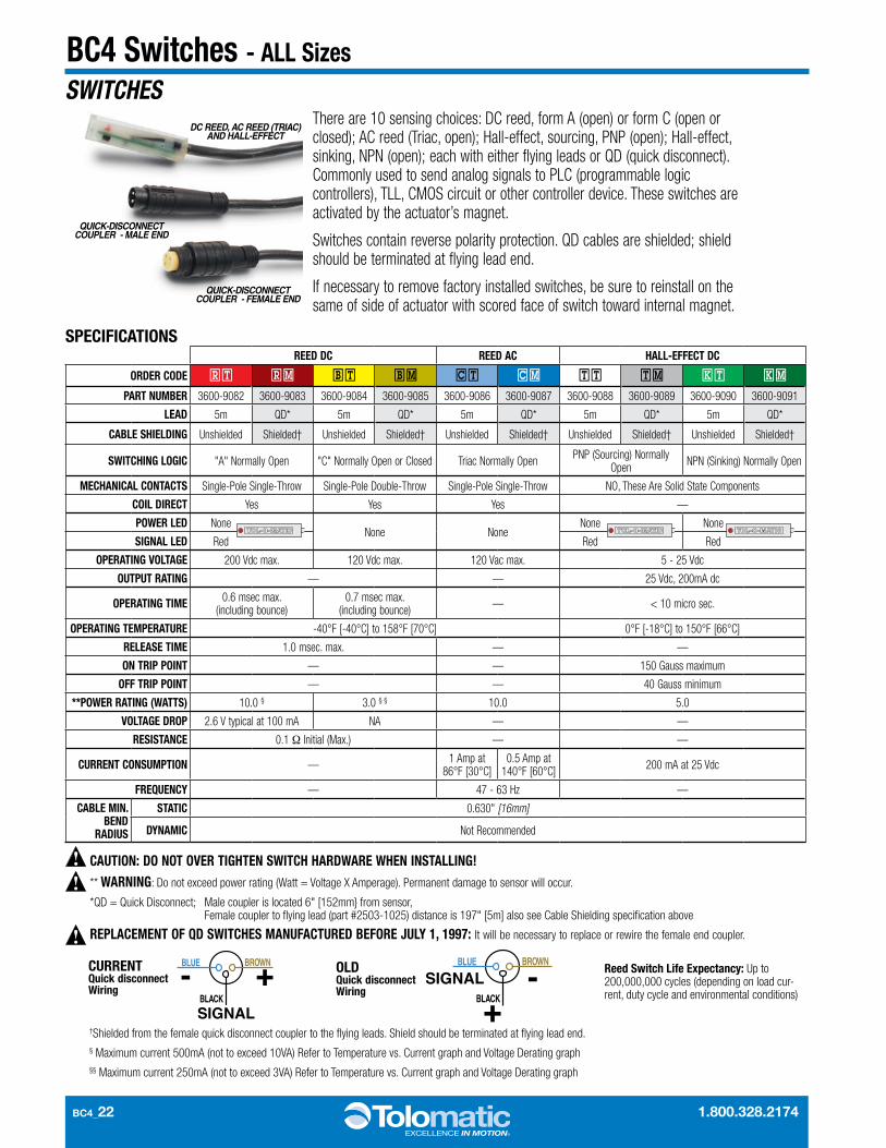
BC4_22 1.800.328.2174
SWITCHESThere are 10 sensing choices: DC reed, form A (open) or form C (open or closed); AC reed (Triac, open); Hall-effect, sourcing, PNP (open); Hall-effect, sinking, NPN (open); each with either flying leads or QD (quick disconnect). Commonly used to send analog signals to PLC (programmable logic controllers), TLL, CMOS circuit or other controller device. These switches are activated by the actuator’s magnet.
Switches contain reverse polarity protection. QD cables are shielded; shield should be terminated at flying lead end.
If necessary to remove factory installed switches, be sure to reinstall on the same of side of actuator with scored face of switch toward internal magnet.
** WARNING: Do not exceed power rating (Watt = Voltage X Amperage). Permanent damage to sensor will occur.
*QD = Quick Disconnect; Male coupler is located 6" [152mm} from sensor, Female coupler to fl ying lead (part #2503-1025) distance is 197" [5m] also see Cable Shielding specifi cation above
REPLACEMENT OF QD SWITCHES MANUFACTURED BEFORE JULY 1, 1997: It will be necessary to replace or rewire the female end coupler.
CAUTION: DO NOT OVER TIGHTEN SWITCH HARDWARE WHEN INSTALLING!
CURRENTQuick disconnect Wiring
BROWN
BLACK
BLUE
+-SIGNAL
OLDQuick disconnect Wiring
BROWN
BLACK
BLUE
+-SIGNAL
†Shielded from the female quick disconnect coupler to the fl ying leads. Shield should be terminated at fl ying lead end.§ Maximum current 500mA (not to exceed 10VA) Refer to Temperature vs. Current graph and Voltage Derating graph§§ Maximum current 250mA (not to exceed 3VA) Refer to Temperature vs. Current graph and Voltage Derating graph
Reed Switch Life Expectancy: Up to 200,000,000 cycles (depending on load cur-rent, duty cycle and environmental conditions)
DC REED, AC REED (TRIAC) AND HALL-EFFECT
QUICK-DISCONNECT COUPLER - MALE END
QUICK-DISCONNECT COUPLER - FEMALE END
SPECIFICATIONSREED DC REED AC HALL-EFFECT DC
ORDER CODE RT RM BT BM CT CM TT TM KT KM
PART NUMBER 3600-9082 3600-9083 3600-9084 3600-9085 3600-9086 3600-9087 3600-9088 3600-9089 3600-9090 3600-9091
LEAD 5m QD* 5m QD* 5m QD* 5m QD* 5m QD*
CABLE SHIELDING Unshielded Shielded† Unshielded Shielded† Unshielded Shielded† Unshielded Shielded† Unshielded Shielded†
SWITCHING LOGIC "A" Normally Open "C" Normally Open or Closed Triac Normally Open PNP (Sourcing) Normally Open NPN (Sinking) Normally Open
MECHANICAL CONTACTS Single-Pole Single-Throw Single-Pole Double-Throw Single-Pole Single-Throw NO, These Are Solid State Components
COIL DIRECT Yes Yes Yes —
POWER LED NoneNone None
None None
SIGNAL LED Red Red Red
OPERATING VOLTAGE 200 Vdc max. 120 Vdc max. 120 Vac max. 5 - 25 Vdc
OUTPUT RATING — — 25 Vdc, 200mA dc
OPERATING TIME 0.6 msec max. (including bounce)
0.7 msec max. (including bounce) — < 10 micro sec.
OPERATING TEMPERATURE -40°F [-40°C] to 158°F [70°C] 0°F [-18°C] to 150°F [66°C]
RELEASE TIME 1.0 msec. max. — —
ON TRIP POINT — — 150 Gauss maximum
OFF TRIP POINT — — 40 Gauss minimum
**POWER RATING (WATTS) 10.0 § 3.0 § § 10.0 5.0
VOLTAGE DROP 2.6 V typical at 100 mA NA — —
RESISTANCE 0.1 Ω Initial (Max.) — —
CURRENT CONSUMPTION — 1 Amp at 86°F [30°C]
0.5 Amp at 140°F [60°C] 200 mA at 25 Vdc
FREQUENCY — 47 - 63 Hz —
CABLE MIN. BEND
RADIUS
STATIC 0.630" [16mm]
DYNAMIC Not Recommended
BC4 Switches - ALL Sizes

www.tolomatic.com BC4_23
PERFORMANCE
THE NOTCHED FACE OF THE SWITCH INDICATES THE SENSING SURFACE AND MUST FACE TOWARD THE MAGNET.
THE NOTCHED GROOVE IN THE ACTUATOR INDICATES THE GROOVE TO INSTALL THE SWITCH. CONTACT TOLOMATIC IF SWITCHES ARE REQUIRED ON ANOTHER SIDE OF ACTUATOR.
0
50
100
150
200
0 100 200 300 400 500
VOLT
AGE
A.C.
or D
.C.
CURRENT D.C (mA)
REED FORM A
REED FORM C
TEMP. vs CURRENT, DC REED VOLTAGE DERATING, DC REEDTEMP. vs CURRENT, AC REED
0
100
200
300
400
500
600
0 20 40 60 80 100 120 140 160
LOAD
CUR
RENT
(mA)
OPERATING TEMPERATURE ( F)
REED FORM C
REED FORM A
0
200
400
600
800
1000
0 20 40 60 80 100 120 140 160
LOAD
CUR
ENT
(mA)
OPERATING TEMPERATURE ( F)
TRIAC
RT & RM DC REED, FORM A
BT & BM DC REED, FORM C
CT & CM AC REED, TRIAC
TT & TM HALL-EFFECT, SOURCING, PNP KT & KM HALL-EFFECT, SINKING, NPN
REEDSWITCH
LOAD
BROWN
BLUE(-)(-)
(+)(+)
REEDSWITCHLOAD
BROWN
BLUE(-)(-)
(+)(+)
OR
AC COM
LOAD
INPUT
TRIACSWITCH
120VacMax.
MOV
BROWNBLUE
REEDSWITCH
COMMONNORMALLY CLOSED
NORMALLY OPEN
BROWNBLACKBLUE
HALL-EFFECTSOURCING
SWITCHBLACK
LOAD
BROWN
BLUE (-)
(+)
(-)
(+)
HALL-EFFECTSINKINGSWITCH
BROWN
BLACK
BLUE (-)
(+)
(-)
(+)
LOAD
WIRING DIAGRAMS INSTALLATION INFORMATION
BC4 Switches - ALL Sizes
BC406BC4M(M)06
BC410BC4M(M)10
BC412BC4M(M)12
DE
A
C
A A
B CC
SENSINGSURFACE
SENSINGSURFACE
SENSINGSURFACE
SIZE BORE A B C D E
06 0 .625 0 .39 0 .55 0 .84 0 .50 1 .25
10 1 .000 0 .22 - 1 .47 0 .50 1 .25
12 1 .250 0 .23 - 1 .66 0 .50 1 .25
15 1 .500 0 .16 - 1 .98 0 .50 1 .25
Dimensions in inches
SIZE BORE A B C D E
M06 12 9.91 13.97 21.34 12.70 31.75
M10 25 5.59 - 37.34 12.70 31.75
M12 32 5.84 - 42.16 12.70 31.75
M15 40 4.06 - 50.29 12.70 31.75
Dimensions in millimeters
DIMENSIONS
Some actuators may require switch mounting on a specific side of the assembly. Call Tolomatic for details.
BC4_24 1.800.328.2174
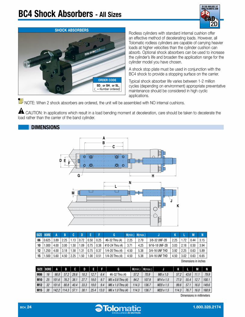
SIZE BORE A B C D E F G H(min .) H(max .) J K L M N06 0 .625 3 .89 2 .25 1 .13 0 .72 0 .50 0 .25 #6-32 Thru (4) 2 .25 2 .79 3/8-32 UNF-2B 2 .25 1 .72 0 .44 3 .15
10 1 .000 4 .00 3 .00 1 .50 1 .09 0 .75 0 .38 #10-24 Thru (4) 3 .71 4 .25 9/16-18 UNF-2B 3 .03 2 .18 0 .50 3 .94
12 1 .250 4 .00 3 .18 1 .58 1 .31 0 .75 0 .37 1/4-20 Thru (4) 4 .50 5 .38 3/4-16 UNF THD 3 .92 2 .25 0 .63 5 .89
15 1 .500 5 .60 4 .50 2 .25 1 .50 1 .00 0 .51 1/4-20 Thru (4) 4 .50 5 .38 3/4-16 UNF THD 4 .50 3 .02 0 .63 6 .65
Dimensions in inches
SIZE BORE A B C D E F G H(min .) H(max .) J K L M NM06 16 98.8 57.2 28.6 18.3 12.7 6.4 #6-32 Thru (4) 57.2 70.9 M8 x 1.0 57.2 43.6 11.1 79.9
M10 25 101.6 76.2 38.1 27.7 19.0 9.7 M5 x 0.8 Thru (4) 94.2 107.9 M14 x 1.5 77.0 55.4 12.7 100.1
M12 32 101.6 80.8 40.4 33.3 19.0 9.4 M6 x 1.0 Thru (4) 114.3 136.7 M20 x 1.5 99.6 57.1 16.0 149.6
M15 38 142.2 114.3 57.1 38.1 25.4 13.0 M6 x 1.0 Thru (4) 114.3 136.7 M20 x 1.5 114.3 76.7 16.0 168.9
Dimensions in millimeters
BC4 Shock Absorbers - All Sizes
Rodless cylinders with standard internal cushion offer an effective method of decelerating loads. However, all Tolomatic rodless cylinders are capable of carrying heavier loads at higher velocities than the cylinder cushion can absorb. Optional shock absorbers can be used to increase the cylinder’s life and broaden the application range for the cylinder model you have chosen.
A shock stop plate must be used in conjunction with the BC4 shock to provide a stopping surface on the carrier.
Typical shock absorber life varies between 1-2 million cycles (depending on environment) appropriate preventative maintenance should be consid ered in high cyclic applications.
NOTE: When 2 shock absorbers are ordered, the unit will be assembled with NO internal cushions.
CAUTION: In applications which result in a load bending moment at deceleration, care should be taken to decelerate the load rather than the carrier of the band cylinder.
SHOCK ABSORBERS
ORDER CODE
SD_ or SH_ or SL_ (_ = Number ordered)
DIMENSIONS
AB
C
D EF
G H
N
JK
L
M
3D CAD AVAILABLE AT WWW.TOLOMATIC.COM
www.tolomatic.com BC4_25
BC4 Shock Absorbers - All Sizes - PERFORMANCE
LOAD (lbs)FI
NAL
VELO
CITY
(in/
sec)
FINA
L VE
LOCI
TY (m
eter
s/se
c)
2.52.3
2.01.8
1.51.3
1.0.8
.5
.25.23 .20.18 .15.13
.10.08
.05
.03
100908070
6050
4030
20
10 98 76
54
3
2
1
12
34
56
78
910
2030
4050
6070
8090
100
.5
.9
1.4
1.8
2.7
3.2
3.6
4.1
4.5
9.1
13.6
18.1
22.7
27.2
31.7
36.3
40.8
45.4
2.3
LOAD (kg)
LOAD (lbs)
FINA
L VE
LOCI
TY (i
n/se
c)
FINA
L VE
LOCI
TY (m
eter
s/se
c)
2.52.3
2.0 1.81.5
1.31.0
.8
.5
.25.23 .20.18 .15.13
.10.08
.05
.03
10090 8070 6050
4030
20
10 98 765
43
2
1
12
34
56
78
910
2030
4050
6070
8090
100
.5
.9
1.4
1.8
2.7
3.2
3.6
4.1
4.5
9.1
13.6
18.1
22.7
27.2
31.7
36.3
40.8
45.4
2.3
LOAD (kg)
12
34
56
78
910
2030
4050
6070
8090
100200
1
23
45
67 89 10
2030
4050
60 7080 90100
200
LOAD (lbs)
FINA
L VE
LOCI
TY (i
n/se
c)
FINA
L VE
LOCI
TY (m
eter
s/se
c)2.52.3 2.01.8 1.51.3
1.0.8
.5
.3 .23
.20 .18
.15 .13
.10.08
.05
.03
.5
.91.
41.
82.
73.
23.
64.
14.
5
9.1
13.6
18.1
22.7
27.2
31.7
36.3
40.8
45.4
2.3
LOAD (kg)
90.7
5.1
12
34
56
78
910
2030
4050
6070
8090
100200
1
23
45
67 89 10
2030
4050
60 7080 90100
200
LOAD (lbs)
2.52.3 2.01.8 1.51.3
1.0.8
.5
.25.23.20 .18.15 .13
.10.08
.05
.03
.5
.91.
41.
82.
73.
23.
64.
14.
5
9.1
13.6
18.1
22.7
27.2
31.7
36.3
40.8
45.4
2.3
LOAD (kg)
90.7
5.1
FINA
L VE
LOCI
TY (i
n/se
c)
FINA
L VE
LOCI
TY (m
eter
s/se
c)
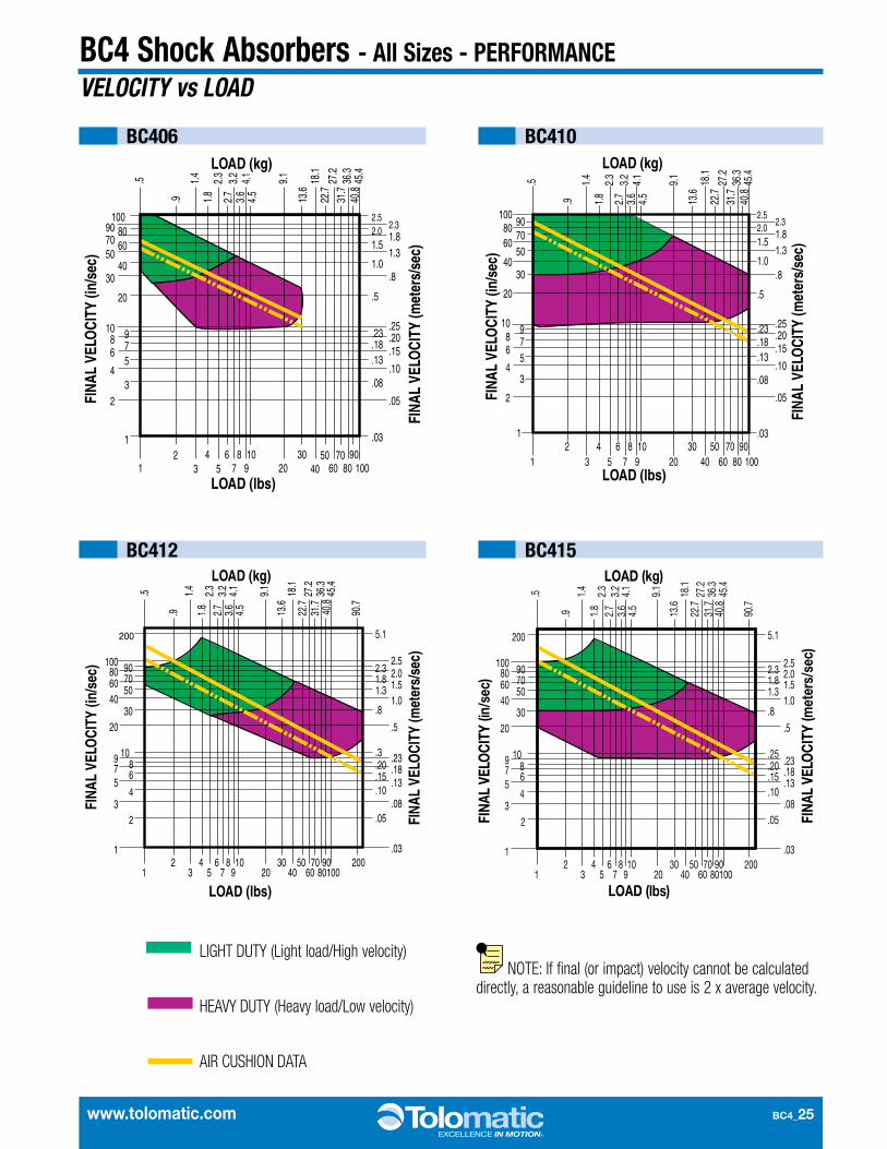
LIGHT DUTY (Light load/High velocity)
HEAVY DUTY (Heavy load/Low velocity)
AIR CUSHION DATA
NOTE: If final (or impact) velocity cannot be calculated directly, a reasonable guideline to use is 2 x average velocity.
VELOCITY vs LOAD
BC406
BC412
BC410
BC415

BC4_26 1.800.328.2174
Application Data Worksheet
STROKE LENGTH _____________ inch (SK ) millimeters
(U.S. Standard) (Metric)
AVAILABLE AIR PRESSURE _____ PSI bar
(U.S. Standard) (Metric)
REQUIRED THRUST FORCE _____ lbf N
(U.S. Standard) (Metric)
LOAD ______________________ lb kg
(U.S. Standard) (Metric)
LOAD CENTER OF dx ______GRAVITY DISTANCE dy ______TO CARRIER CENTER dz ______
inch millimeters(U.S. Standard) (Metric)
ORIENTATION
FRONT VIEWβ
Lz
XZ
SIDE VIEW
α
Lz
YZ
ACTUATORACTUATORCARRIER
CARRIER
CENTER OF GRAVITYdz
dYdx
CENTER OF GRAVITY
dzd Y
dxACTUATORACTUATOR
CARRIERCARRIER
ACTUATORACTUATOR
CARRIERCARRIER
CENTER OF GRAVITY
dyd Zdyd Z
dx
dx
CENTER OF GRAVITY
CARR
IER AC
TUAT
ORCA
RRIE
R ACTU
ATOR
dzdzd Y
FORCES APPLIED Fz ______TO CARRIER Fy ______
lbf N(U.S. Standard) (Metric)
BENDING MOMENTS Mx ______APPLIED TO CARRIER My ______
in-lbs N-m Mz ______(U.S. Standard) (Metric)
FINAL VELOCITY _____________ in/sec mm/sec
(U.S. Standard) (Metric)
MOVE TIME sec. _____________
NO. OF CYCLES _____________ per minute per hour
Horizontal Side Horizontal Down
Vertical Angled α __________ β ____________
Fax (1-763-478-8080) or call Tolomatic (1-800-328-2174) with the above information. We will provide any assistance needed to determine the proper actuator.
OTHER ISSUES: (i.e. Environment, Temperature, Contamination, etc.)
Contact information:Online Sizing & Selection Software at www.tolomatic.com
or call us at 1-800-328-2174
SIZING
ACTUATOR
www.tolomatic.com BC4_27
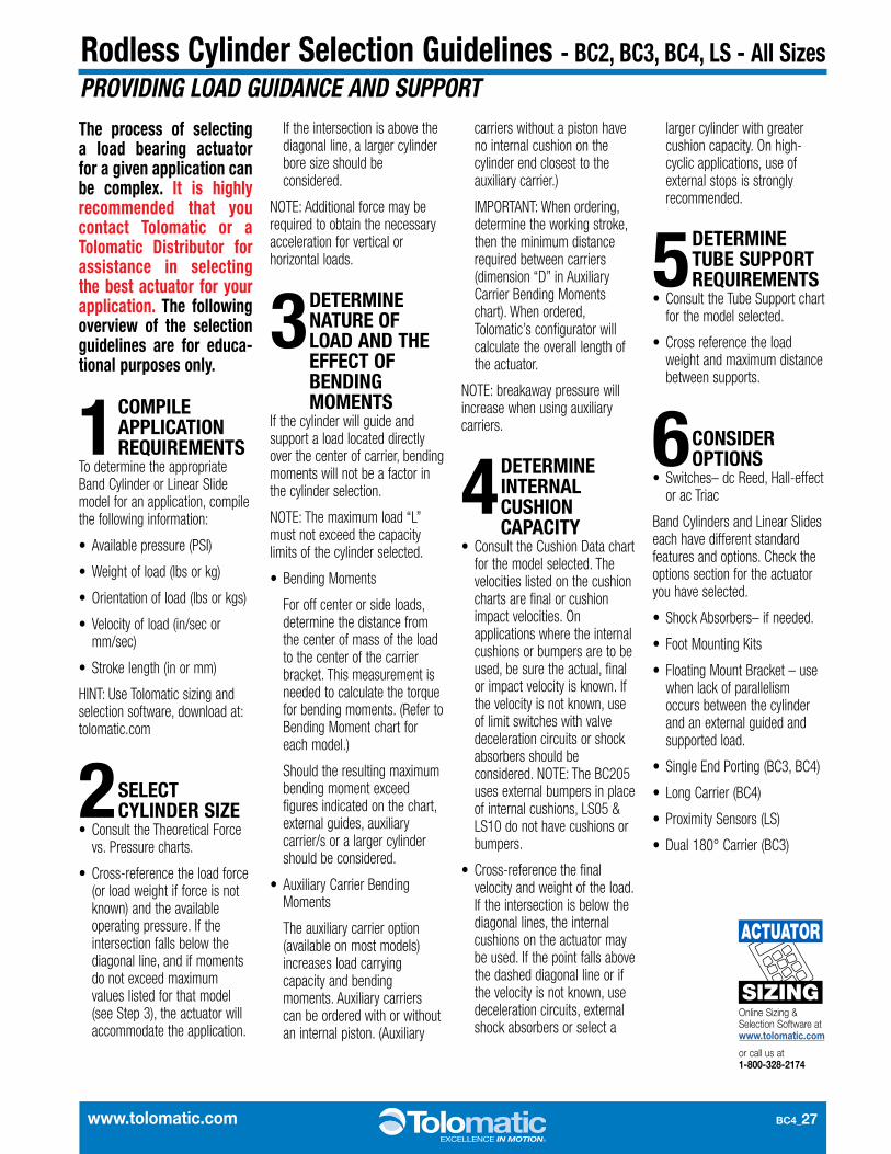
Rodless Cylinder Selection Guidelines - BC2, BC3, BC4, LS - All SizesPROVIDING LOAD GUIDANCE AND SUPPORTThe process of selecting a load bearing actuator for a given application can be complex. It is highly recommended that you contact Tolomatic or a Tolomatic Distributor for assistance in selecting the best actuator for your application. The following overview of the selection guidelines are for educa-tional purposes only.
1 COMPILE APPLICATION REQUIREMENTS
To determine the appropriate Band Cylinder or Linear Slide model for an application, compile the following information:
• Available pressure (PSI)
• Weight of load (lbs or kg)
• Orientation of load (lbs or kgs)
• Velocity of load (in/sec or mm/sec)
• Stroke length (in or mm)
HINT: Use Tolomatic sizing and selection software, download at: tolomatic.com
2 SELECT CYLINDER SIZE
• Consult the Theoretical Force vs. Pressure charts.
• Cross-reference the load force (or load weight if force is not known) and the available operating pressure. If the intersection falls below the diagonal line, and if moments do not exceed maximum values listed for that model (see Step 3), the actuator will accommodate the application.
If the intersection is above the diagonal line, a larger cylinder bore size should be considered.
NOTE: Additional force may be required to obtain the necessary acceleration for vertical or horizontal loads.
3 DETERMINE NATURE OF LOAD AND THE EFFECT OF BENDING MOMENTS
If the cylinder will guide and support a load located directly over the center of carrier, bending moments will not be a factor in the cylinder selection.
NOTE: The maximum load “L” must not exceed the capacity limits of the cylinder selected.
• Bending Moments
For off center or side loads, determine the distance from the center of mass of the load to the center of the carrier bracket. This measurement is needed to calculate the torque for bending moments. (Refer to Bend ing Moment chart for each model.)
Should the resulting maximum bending moment exceed figures indicated on the chart, external guides, auxiliary carrier/s or a larger cylinder should be considered.
• Auxiliary Carrier Bending Moments
The auxiliary carrier option (available on most models) increases load carrying capacity and bending moments. Auxiliary carriers can be ordered with or without an internal piston. (Auxiliary
carriers without a piston have no internal cushion on the cylinder end closest to the auxiliary carrier.)
IMPORTANT: When ordering, determine the working stroke, then the minimum distance required between carriers (dimension “D” in Auxiliary Carrier Bending Mom ents chart). When ordered, Tolomatic’s configurator will calculate the overall length of the actuator.
NOTE: breakaway pressure will increase when using auxiliary carriers.
4 DETERMINE INTERNAL CUSHION CAPACITY
• Consult the Cushion Data chart for the model selected. The velocities listed on the cushion charts are final or cushion impact velocities. On applications where the internal cushions or bumpers are to be used, be sure the actual, final or impact velocity is known. If the velocity is not known, use of limit switches with valve deceleration circuits or shock absorbers should be considered. NOTE: The BC205 uses external bumpers in place of internal cushions, LS05 & LS10 do not have cushions or bumpers.
• Cross-reference the final velocity and weight of the load. If the intersection is below the diagonal lines, the internal cushions on the actuator may be used. If the point falls above the dashed diagonal line or if the velocity is not known, use deceleration circuits, external shock absorbers or select a
larger cylinder with greater cushion capacity. On high-cyclic applications, use of external stops is strongly recommended.
5 DETERMINE TUBE SUPPORT REQUIREMENTS
• Consult the Tube Support chart for the model selected.
• Cross reference the load weight and maximum distance between supports.
6 CONSIDER OPTIONS
• Switches– dc Reed, Hall-effect or ac Triac
Band Cylinders and Linear Slides each have different standard features and options. Check the options section for the actuator you have selected.
• Shock Absorbers– if needed.
• Foot Mounting Kits
• Floating Mount Bracket – use when lack of parallelism occurs between the cylinder and an external guided and supported load.
• Single End Porting (BC3, BC4)
• Long Carrier (BC4)
• Proximity Sensors (LS)
• Dual 180° Carrier (BC3)
Online Sizing & Selection Software at www.tolomatic.com
or call us at 1-800-328-2174
SIZING
ACTUATOR

BC4_28 1.800.328.2174
Application Guidelines
The following conditional statements are intended as general guidelines for use of Tolomatic actuators. Since all applications have their own specific operating requirements, consult Tolomatic, Inc. or your local Tolomatic distributor if an application is unconventional or if questions arise regarding the selection process.
CUSHION NEEDLE ADJUSTMENT (BC2, BC3, BC4, CC, SA, DP, TC ONLY)
Adjust the cushion needles in the cylinder heads carefully to obtain a smooth, hesitation free deceleration for your particular application. If there are questions on proper adjustment, please consult Tolomatic, Inc.
LUBRICATION GUIDELINESAll Tolomatic actuators (except Cable Cylinders) are prelubricated at the factory. To ensure maximum actuator life, the following guidelines should be followed.
• Filtration
We recommend the use of dry, filtered air in our products. “Filtered air” means a level of 10 Micron or less. “Dry” means air should be free of appreciable amounts of moisture. Regular maintenance of installed
filters will generally keep excess moisture in check.
• External Lubricators (optional)
The factory prelubrication of Tolomatic actuators will provide optimal performance without the use of external lubrication. However, external lubricators can further extend service life of pneumatic actuators if the supply is kept constant.
Oil lubricators, (mist or drop) should supply a minimum of 1 drop per 20 standard cubic feet per minute to the
cylinder. As a rule of thumb, double that rate if water in the system is suspected. Demanding conditions may require more lubricant.
If lubricators are used, we recommend a non-detergent, 20cP @ 140˚F 10-weight lubricant. Optimum conditions for standard cylinder operation are +32˚ to +150˚F (+0˚ to 65.5˚C).
NOTE: Use of external lubricators may wash away the factory installed lubrication. External lubricants must be maintained in a constant supply or the results will be a dry actuator prone to premature wear.
• Sanitary Environments
Oil mist lubricators must dispense “Food Grade” lubricants to the air supply. Use fluids with ORAL LD50 toxicity ratings of 35 or higher such as Multitherm® PG-1 or equivalent. Demanding conditions can require a review of the application.
Velocity calculations for all rodless cylinders need to differentiate between final velocity and average velocity. For example: Stroking a 100-inch BC3 model in one second yields an average velocity of 100 inches per second. To properly determine the inertial forces for cushioning, it is important to know the
final (or impact) velocity. Rodless cylinders accelerate and decelerate at each end of the stroke. Therefore this acceleration must be considered (see diagram).
If final (or impact) velocity cannot be calculated directly, a reasonable guideline is to use 2 x average velocity.
FINAL VELOCITY CALCULATION
VELO
CITY
Start Time End
Final (impact)
Average
www.tolomatic.com BC4_29
BC4 Service Parts Ordering - ALL Sizes
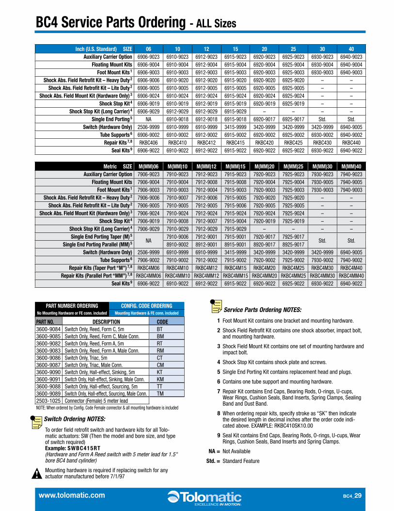
Service Parts Ordering NOTES:
1 Foot Mount Kit contains one bracket and mounting hardware .
2 Shock Field Retrofit Kit contains one shock absorber, impact bolt, and mounting hardware .
3 Shock Field Mount Kit contains one set of mounting hardware and impact bolt .
4 Shock Stop Kit contains shock plate and screws .
5 Single End Porting Kit contains replacement head and plugs .
6 Contains one tube support and mounting hardware .
7 Repair Kit contains End Caps, Bearing Rods, O-rings, U-cups, Wear Rings, Cushion Seals, Band Inserts, Spring Clamps, Sealing Band and Dust Band .
8 When ordering repair kits, specify stroke as “SK” then indicate the desired length in decimal inches after the order code indi-cated above . EXAMPLE: RKBC410SK10 .00
9 Seal Kit contains End Caps, Bearing Rods, O-rings, U-cups, Wear Rings, Cushion Seals, Band Inserts and Spring Clamps .
NA = Not Available
Std. = Standard Feature
Switch Ordering NOTES:
To order field retrofit switch and hardware kits for all Tolo-matic actuators: SW (Then the model and bore size, and type of switch required)Example: SWBC415RT (Hardware and Form A Reed switch with 5 meter lead for 1.5" bore BC4 band cylinder)
Mounting hardware is required if replacing switch for any actuator manufactured before 7/1/97
PART NUMBER ORDERING CONFIG. CODE ORDERINGNo Mounting Hardware or FE conn. included Mounting Hardware & FE conn. included
PART NO. DESCRIPTION CODE3600-9084 Switch Only, Reed, Form C, 5m BT3600-9085 Switch Only, Reed, Form C, Male Conn . BM3600-9082 Switch Only, Reed, Form A, 5m RT3600-9083 Switch Only, Reed, Form A, Male Conn . RM3600-9086 Switch Only, Triac, 5m CT3600-9087 Switch Only, Triac, Male Conn . CM3600-9090 Switch Only, Hall-effect, Sinking, 5m KT3600-9091 Switch Only, Hall-effect, Sinking, Male Conn . KM3600-9088 Switch Only, Hall-effect, Sourcing, 5m TT3600-9089 Switch Only, Hall-effect, Sourcing, Male Conn . TM2503-1025 Connector (Female) 5 meter leadNOTE: When ordered by Config . Code Female connector & all mounting hardware is included
Inch (U.S. Standard) SIZE 06 10 12 15 20 25 30 40Auxiliary Carrier Option 6906-9023 6910-9023 6912-9023 6915-9023 6920-9023 6925-9023 6930-9023 6940-9023
Floating Mount Kits 6906-9004 6910-9004 6912-9004 6915-9004 6920-9004 6925-9004 6930-9004 6940-9004Foot Mount Kits 1 6906-9003 6910-9003 6912-9003 6915-9003 6920-9003 6925-9003 6930-9003 6940-9003
Shock Abs. Field Retrofit Kit – Heavy Duty 2 6906-9006 6910-9020 6912-9020 6915-9020 6920-9020 6925-9020 – –Shock Abs. Field Retrofit Kit – Lite Duty 2 6906-9005 6910-9005 6912-9005 6915-9005 6920-9005 6925-9005 – –
Shock Abs. Field Mount Kit (Hardware Only) 3 6906-9024 6910-9024 6912-9024 6915-9024 6920-9024 6925-9024 – –Shock Stop Kit 4 6906-9019 6910-9019 6912-9019 6915-9019 6920-9019 6925-9019 – –
Shock Stop Kit (Long Carrier) 4 6906-9029 6912-9029 6912-9029 6915-9029 – – – –Single End Porting 5 NA 6910-9018 6912-9018 6915-9018 6920-9017 6925-9017 Std . Std .
Switch (Hardware Only) 2506-9999 6910-9999 6910-9999 3415-9999 3420-9999 3420-9999 3420-9999 6940-9005Tube Supports 6 6906-9002 6910-9002 6912-9002 6915-9002 6920-9002 6925-9002 6930-9002 6940-9002
Repair Kits 7, 8 RKBC406 RKBC410 RKBC412 RKBC415 RKBC420 RKBC425 RKBC430 RKBC440Seal Kits 9 6906-9022 6910-9022 6912-9022 6915-9022 6920-9022 6925-9022 6930-9022 6940-9022
Metric SIZE M(MM)06 M(MM)10 M(MM)12 M(MM)15 M(MM)20 M(MM)25 M(MM)30 M(MM)40Auxiliary Carrier Option 7906-9023 7910-9023 7912-9023 7915-9023 7920-9023 7925-9023 7930-9023 7940-9023
Floating Mount Kits 7906-9004 7910-9004 7912-9008 7915-9008 7920-9004 7925-9004 7930-9005 7940-9005Foot Mount Kits 1 7906-9003 7910-9003 7912-9004 7915-9003 7920-9003 7925-9003 7930-9003 7940-9003
Shock Abs. Field Retrofit Kit – Heavy Duty 2 7906-9006 7910-9007 7912-9006 7915-9005 7920-9020 7925-9020 – –Shock Abs. Field Retrofit Kit – Lite Duty 2 7906-9005 7910-9005 7912-9005 7915-9006 7920-9005 7925-9005 – –
Shock Abs. Field Mount Kit (Hardware Only) 3 7906-9024 7910-9024 7912-9024 7915-9024 7920-9024 7925-9024 – –Shock Stop Kit 4 7906-9019 7910-9008 7912-9007 7915-9004 7920-9019 7925-9019 – –
Shock Stop Kit (Long Carrier) 4 7906-9029 7910-9029 7912-9029 7915-9029 – – – –Single End Porting Taper (M) 5
NA7910-9006 7912-9001 7915-9001 7920-9017 7925-9017
Std . Std .Single End Porting Parallel (MM) 5 8910-9002 8912-9001 8915-9001 8920-9017 8925-9017
Switch (Hardware Only) 2506-9999 6910-9999 6910-9999 3415-9999 3420-9999 3420-9999 3420-9999 6940-9005Tube Supports 6 7906-9002 7910-9002 7912-9002 7915-9002 7920-9002 7925-9002 7930-9002 7940-9002
Repair Kits (Taper Port “M”) 7, 8 RKBC4M06 RKBC4M10 RKBC4M12 RKBC4M15 RKBC4M20 RKBC4M25 RKBC4M30 RKBC4M40Repair Kits (Parallel Port “MM”) 7, 8 RKBC4MM06 RKBC4MM10 RKBC4MM12 RKBC4MM15 RKBC4MM20 RKBC4MM25 RKBC4MM30 RKBC4MM40
Seal Kits 9 6906-9022 6910-9022 6912-9022 6915-9022 6920-9022 6925-9022 6930-9022 6940-9022
BC4_30 1.800.328.2174
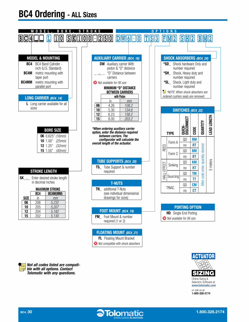
BC4 Ordering - ALL Sizes
TUBE SUPPORTS (BC4_20)
TS_ Tube Support & number required
LONG CARRIER (BC4_14)
L Long carrier available for all sizes
T-NUTS TN_ additional T-Nuts
(see individual dimensional drawings for sizes)
FOOT MOUNT (BC4_19)
FM_ Foot Mount & number required (1 or 2)
PORTING OPTION HD Single End Porting Not available for 06 size
SHOCK ABSORBERS (BC4_24)
*SD_ Shock hardware Only and number required
*SH_ Shock, Heavy duty and number required
*SL_ Shock, Light duty and number required
*NOTE: When shock absorbers are ordered cushion seals are removed.
FLOATING MOUNT (BC4_21)
FL Floating Mount Bracket Not compatible with shock absorbers
Not all codes listed are compati-ble with all options. Contact Tolomatic with any questions.
M O D E L , B O R E , S T R O K E O P T I O N S
MODEL & MOUNTINGBC4 BC4 Band Cylinder -
inch (U.S. Standard)BC4M metric mounting with
taper portBC4MM metric mounting with
parallel port
STROKE LENGTHSK _ _._ _ Enter desired stroke length
in decimal inches
MAXIMUM STROKE
SIZEBC4 BC4M(MM)in mm
06 206 5,23210 205 5,20712 204 5,18215 202 5,130
BORE SIZE06 0.625” (16mm)10 1.00” (25mm)12 1.25” (32mm)15 1.50” (40mm)
BC4__ L 10 SK100.250 DW6.0 TS3 FM2 SH2 BM2
AUXILIARY CARRIER (BC4_16)
DW Auxiliary carrier With piston & “D” distance
_ _._ _ “D” Distance between carriers
Not available for 06 size
MINIMUM “D” DISTANCE BETWEEN CARRIERS
with Pistonin mm
06 4.26 108.210 5.30 134.612 6.23 158.215 8.00 203.2
*When ordering auxiliary carrier option, enter the distance required
between carriers. The configurator will calculate the
overall length of the actuator.
SWITCHES (BC4_22)
TYPE QUIC
K-DI
SCON
NECT
CODE
QUAN
TITY
LEAD
LEN
GTH
REED
Form AQD RM
Afte
r cod
e en
ter q
uant
ity d
esire
d
5 m
eter
s
no RT
Form CQD BMno BT
HALL
-EFF
ECT
SinkingQD KMno KT
SourcingQD TMno TT
TRIACQD CMno CT
Online Sizing & Selection Software at www.tolomatic.com
or call us at 1-800-328-2174
SIZING
ACTUATOR