behavior of long prestressed pavement slabs and design ... · behavior of long prestressed pavement...
TRANSCRIPT
TECHNICAL REPORT ST AND ARO TIT LE PAC E I. A.p.rt N •. 2. Go".m ... ettl Ace ... ;." N ••
FHWA/TX-87/71+401-3
•• Till •• "d Subtitl.
BEHAVIOR OF LONG PRESTRESSED PAVEMENT SLABS AND DESIGN METHODOLOGY
7. Autho,1 .)
Alberto Mendoza Diaz, Ned H. Burns, and B. Frank McCullough 9. P.rforminll 0., .... lotion H_ .... d Add •• "
Center for Transportation Research The University of Texas at Austin Austin, Texas 78712-1075
S. R.po,I Dol.
September 1986 6. P.rfor ... i", 0"0"'101,.,, Cod.
8. P.,lor ... i"1I Or,o", lolion R.port No.
Research Report 401-3
10. Won. Unil No.
11. Cont,oct 0' G,ant No.
Research Study 3-8-84-401
h1-;:-::-:-'--:---:;--"'7":~-:-:--:----------------~ 13. Typ. of A.po,t ond P.riod Co".r.d 12. Spon.ot'", A, ... cl' H_. ""d Add ....
Texas State Department of Highways and Public Transportation; Transportation Planning Division
P.O. Box 505 1 Austin, Texas 78763-5051 IS. Suppl ....... I.,1' Hal ••
Interim
U. S,. .. a.,in, A,.ncy C.d.
Study conducted in cooperation with the U. S. Department of Transportation, Federal Highway Administration. Research Study Title: "Prestressed Concrete Pavement Design-Design and Construction of Overlay Applications ll
16. Abat.act The work plan for the design of the McLennan County prestressed concrete pavement
(PCP) overlay consisted of three distinct aspects: (a) a thorough review of the available literature on design of PCP to determine the variables that are relevant to the design of slab length, joint details, thickness and prestress level in the longitudinal and transverse directions, (b) development of models and procedures for accurately predicting the effect of these variables on the elements of the PCP structure, and (c) development of a PCP design based on (a) and (b) to implement in the project. The design of the PCP slabs was also to include recommendations with regard to adequate time of slab placement and application of prestress forces.
The completion of aspects (a) through (c) led to the study of the effect of environfactors on PCP slabs. Environmental variables producing movements, stresses and deflections in the slabs are: (1) changes of temperature and moisture content of the pavement; (2) curling produced by temperature differentials from top to bottom of slabs; and (3) warping produced by top to bottom moisture differentials.
The main objective of this study is to present the development of a model to predict the behavior of long PCP slabs and incorporate the predictions from the model into a design procedure. In this study, the derivation of a model for friction considering its inelastic nature is presented. The working scheme of computer program PSCPl which incorporates the major findings from this study is also shown. The information generated by the program can be used for designing thickness, prestress level and slab length of the PCP. To check the reliability of themodels inside PSCPl, a comparison of predicted responses from the model is made against responses observed at the McLennan County PCP overlay. A scheme for a design methodology based on design charts and predictions from computer program PSCPl is finally presented. 17. K.y Wotds
concrete, overlay, prestressed concrete pavement (PCP), posttensioning, environmental factors, friction, elasticity, temperature change, curling, warping, regression analysis, design methodology
No restrictions. This document is available to the public through the National Technical Information Service, Springfield, Virginia 22161.
19. Security CI ... if. (.f this ,.,..,.,
Unclassified
2ID. Security CI ... ". (of thl' II ... )
Unc1ass ified
21. No •• f p.... 22. P,lc.
302
Fomt DOT F 1700.7 , .... »
\
BEHAVIOR OF LONG PRESTRESSED PAVEMENT SLABS AND DESIGN METHODOLOGY
by
Alberto Mendoza Diaz Ned H. Burns
B. Frank McCullough
Research Report 401-3
Prestressed Concrete Pavement DesignDesign and Construction of Overlay Applications
Research Project 3-8-84-401
conducted for
Texas State Department of Highways and Public Transportation
in cooperation with the U.S. Department of Transportation
Federal Highway Administration
by the
Center for Transportation Research Bureau of Engineering Research
The University of Texas at Austin
September 1986

The contents of this report reflect the views of the authors. who are responsible for
the facts and the accuracy of the data presented herein. The contents do not necessarily reflect
the official views or policies of the Federal Highway Administration. This report does not
constitute a standard. specification, or regulation.
Ii
PREFACE
Research Report 401-3, "Behavior of Long Prestressed Pavement Slabs and Design
Methodology," is the third report for Research Project 401, "Prestressed Concrete Pavement
Design - Design and Construction of Overlay Applications," which is being conducted at the
Center for Transportation Research (CTR), The University of Texas at Austin, as part of the
Cooperative Highway Research Program sponsored by the Texas State Department of Highways
and Public Transportation (SDHPT) and the Federal Highway Administration (FHWA).
The purpose of this report is to present the development of a model to predict the
behavior of long prestressed concrete pavement (PCP) slabs and incorporate the predictions
from the model into a design procedure. This is accomplished by making, first, a review of the
important variables affecting PCP behavior. Then, a model for predicting the stresses in the
slab due to subbase frictional resistance is derived. The model derived considers the inelastic
nature of the slab-subbase friction forces. The working scheme of computer program PSCP1,
which incorporates the major findings from this study, is also described. A comparison of
predicted responses from computer program PSCP1 against observed responses at the
McLennan County PCP overlay is shown. Finally, some of the possible applications of
computer program PSCP1 in connection with the design of several PCP structural elements
are described.
The authors are indebted to all members of the CTR staff and professors of the Civil and
Mechanical Engineering Departments who participated in the development of this study.
Thanks are extended to Lyn Gabbert and Rachel Hinshaw for preparing the drafts of the
manuscript. Special acknowledgement is made to the Texas State Department of Highways and
Public Transportation personnel for their cooperation, in particular Mr. James L. Brown and
Jerry Daleiden (D-8).
September 1986
iii
Alberto Mendoza Diaz
Ned H. Burns
B. Frank McCullough

!!!!!!!!!!!!!!!!!!!"#$%!&'()!*)&+',)%!'-!$-.)-.$/-'++0!1+'-2!&'()!$-!.#)!/*$($-'+3!
44!5"6!7$1*'*0!8$($.$9'.$/-!")':!
UST OF REPORTS
Report No. 401-1, "Very Early Post-tensioning of Prestressed Concrete Pavements,"
by J. Scott O'Brien, Ned H. Burns, and B. Frank McCullough, presents the results of tests
performed to determine the very early post-tensioning capacity of prestressed concrete
pavement slabs, and gives recommendations for a post-tensioning schedule within the first 24
hours after casting.
Report No. 401-2, "New Concepts in Prestressed Concrete Pavement," by Neil. D.
Cable, Ned H. Burns and B. Frank McCullough, presents the following: (a) a review of the
available literature to ascertain the current state of the art of prestressed concrete pavement;
(b) a critical evaluation of the design, construction, and performance of several FHWA
sponsored prestressed concrete pavement projects which were constructed during the 1970s;
and (c) several new prestressed concrete pavement concepts which were developed based on
(a) and (b).
Report No. 401-3, "Behavior of Long Prestressed Pavement Slabs and Design
Methodology," by Alberto Mendoza Diaz, Ned H. Burns, and B. Frank McCullough, presents the
development of a model to predict the behavior of long prestressed concrete pavement (PCP)
slabs and incorporate the predictions from the model into a design procedure.
v

!!!!!!!!!!!!!!!!!!!"#$%!&'()!*)&+',)%!'-!$-.)-.$/-'++0!1+'-2!&'()!$-!.#)!/*$($-'+3!
44!5"6!7$1*'*0!8$($.$9'.$/-!")':!

ABSTRACT
The work plan for the design of the McLennan County prestressed concrete pavement
(PCP) overlay consisted of three distinct aspects: (a) a thorough review of the available
literature on design of PCP to determine the variables that are relevant to the design of slab
length. joint details. thickness and prestress level in the longitudinal and transverse
directions. (b) development of models and procedures for accurately predicting the effect of
these variables on the elements of the PCP structure. and (c) development of a PCP design
based on (a) and (b) to implement in the project. The design of the PCP slabs was also to
include recommendations with regard to adequate time of slab placement and application of
prestress forces.
The completion of aspects (a) through (c) led to the study of the effect of
environmental factors on PCP slabs. Environmental variables producing movements. stresses
and deflections in the slabs are:
( 1 ) Changes of temperature and moisture content of the pavement.
( 2 ) Curling produced by temperature differentials from top to bottom of slabs.
( 3 ) Warping produced by top to bottom moisture differentials.
The main objective of this study is to present the development of a model to predict the
behavior of long PCP slabs and incorporate the predictions from the model into a design
procedure. In this study, the derivation of a model for friction considering its inelastic nature
is presented. The working scheme of computer program PSCP1 which incorporates the major
findings from this study is also shown. The information generated by the program can be used
for designing thickness, prestress level and slab length of the PCP. To check the reliability of
the models inside PSCP1, a comparison of predicted responses from the model is made against
responses observed at the McLennan County PCP overlay. A scheme for a design methodology
based on design charts and predictions from computer program PSCP1 is finally presented.
vii

KEYWORDS: Concrete, overlay, prestressed concrete pavement (PCP), posttensioning,
environmental factors, friction, elasticity, inelasticity, temperature change,
temperature reversal, curling, warping, stress, deformation, deflection,
movement, computer program, regression analysis, design methodology.
viii

SUMMARY
The main objective of this study was to present the development of a model to predict
the behavior of long Prestressed Concrete Pavement (PCP) slabs and incorporate the
predictions from the model into a design procedure. In this study, the derivation of a model for
friction considering its inelastic nature is presented. The working scheme of computer
program PSCP1 which incorporates the major findings from this study is also shown. The
information generated by the program can be used for designing thickness, prestress level and
slab length of the PCP. To check the reliability of the models inside PSCP1, a comparison of
predicted responses from the model is made against responses observed at the McLennan
County PCP overlay. A scheme for a design methodology based on design charts and predictions
from computer program PSCP1 is finally presented.
The study indicated that an elastic design of PCP slabs is not sufficient inasmuch as this
method is not sensitive to wheel load repetitions. A fatigue analysis is particularly
indispensable for deSigning pavements of highly trafficked facilities.
The friction forces under rigid pavements resemble elastic forces for small
displacements (less than a maximum of 0.02 inch). However, for displacements of a higher
magnitude, like those experienced by the long PCP slabs, for daily temperature cycles, the
frictional resistance is substantially inelastic. In this case, reversals of slab movement
result in reversals of the direction of the friction forces under the slab and changes in the
nature of the concrete stresses (tensile to compressive or vice versa).
It is recommended that the design procedure for PCP should be improved by including
the beneficial effect of certain environmental factors in resisting wheel loads, e.g., the
permanent moisture differential through the slab depth. This permanent moisture differential
causes the precompression due to the prestress to concentrate at the bottom of the pavement.
The present state of the technology does not allow the designer to incorporate the effects of this
factor in the design with sufficient reliability.
Criteria should be developed for evaluating long~term (20 years or more)
performance of in~service PCP as related to wheel load repetitions and allowable stresses to
use in design.
ix

!!!!!!!!!!!!!!!!!!!"#$%!&'()!*)&+',)%!'-!$-.)-.$/-'++0!1+'-2!&'()!$-!.#)!/*$($-'+3!
44!5"6!7$1*'*0!8$($.$9'.$/-!")':!

IMPLEMENTATION STATEMENT
This document is intended to represent a progression of thought regarding the behavior
of long PCP slabs.
It is recommended that the programs and design techniques developed in this study be
implemented on the procedures currently in use by the Texas State Department of Highways
and Public Transportation for the design of rigid pavements and overlays.
xi

!!!!!!!!!!!!!!!!!!!"#$%!&'()!*)&+',)%!'-!$-.)-.$/-'++0!1+'-2!&'()!$-!.#)!/*$($-'+3!
44!5"6!7$1*'*0!8$($.$9'.$/-!")':!
TABLE OF CONTENTS
PREFACE................................................................................................................................. iii
UST OF REPORTS................................................... .......................... ...... ............ ...... .............. v
ABSTRACT............................................................................................................................... vii
SUMMARy............................................................................................................................... ix
IMPLEMENTATION STATEMENT ...... .......... ............................. ........... ......... ....... ..................... xi
CHAPTER 1. INTRODUCTION
OVERVIEW OF PRESTRESSED PAVEMENTS .......... ............................ .......................... 1
Definition ....................................................................................................... 1
Advantages ........................ .......................................... .......... ...... ...... .............. 1
Types of Prestressed Pavements .............................................. .............. ....... 2
History of Prestressed Pavement .............. ................ ...... .............................. 3
CTR RESEARCH PROJECTS ON ~P ............................... ........................ .... ................. 5
OBJECTIVES OF THE STUDy........................................................................................ 5
SCOPE OF THE STUDy............. .......... .................... .... ...... ................ .. ...... .................... 7
CHAPTER 2. FACTORS TO CONSIDER IN THE DESIGN OF PCP STRUCTURAL ELEMENTS
SLAB LE:NGTH ... ., ............. '" ...... "' ................... 4O ............ "' ..................... " ................................................................................................................ ".... .... 9
Factors Affecting Joint Movements................................................................ 9
The Effect of the Frictional Resistance ....... ................. ...................... ........... 1 0
Effect of the Prestressing Technique ............................................................. 1 2
JOINT DESiGN....................... ...................................................................................... 1 5
EFFECT OF ENVIRONMENTAL CHANGES ON THE PAVEMENT STRUCTURE .............. .... 1 8
Friction Restraint Stresses ........................................................................... 1 8
Stresses Due to Temperature Gradient.......................................................... 21
Stresses Due to Moisture Differential........................................................... 21
Variations of the Prestress LeveL....................... .......................................... 22
xiii
Distribution of Prestress .............................................................................. 22
THICKNESS AND LEVEL OF PRESTRESS .... ................ ........................................ ......... 23
Wheel Load Stresses..... ............... ............ ... .................. ...... .................. .......... 24
Allowable Concrete Flexural Stress .............................................................. 24
Prestress Force in the Longitudinal Direction.............................................. 24
Analysis in the Transverse Direction............................................................ 26
Fatigue Considerations ................................................................................... 26
PRESTRESSING STEEL................................................................................................ 26
SUMMARy................................................................................................................... 27
CHAPTER 3. NATURE OF THE FRICTIONAL RESISTANCE UNDER RIGID PAVEMENTS
THE FRICTION FORCE ..................... .... ...... ................ .......... ........ ........ .......... ........ ...... 29
FEATURES OF SLAB FRICTIONAL RESISTANCE... ............... ............... .......................... 3 1
Goldbeck ............................. .......... .. ........................................................ ...... .. 3 1
Timms ............................................................................................................ 32
Other Field Tests............................................................................................ 32
HYSTERETIC BEHAVIOR ........ .......... .................... ..... ....... .......................... .................. 34
NATURE OF THE FRICTIONAL RESISTANCE UNDER RIGID PAVEMENTS ....... .............. 39
Modeling of Friction Forces ........... ................ .......................................... ...... 39
SUMMARy................................................................................................................... 51
CHAPTER 4. PROBLEM STATEMENT AND MODEL FOR FRICTION
PROBLEM STATEMENT. .......................................................... ................ ............ .... .... 53
General Assumptions............................................... ....... ......... ................ ....... 56
FRICTION MODEL........................................................................................................ 57
Assumptions of the Model................... .................. ................ ....... ........... ........ 60
Submodel for Contraction and Expansion........................................... ........ .... 61
Submodel for Movement Reversal Intervals ................................................. 66
Simulation of Consecutive Cycles .................................................................. 75
xiv
LENGTH CHANGES DUE TO SEASONAl CYCLES AND OTHER La.JG TERM EFFECTS...... 76
Solution for Reinforced and Cracked Pavements ......... .................... .............. 79
SUMMARy................................................................................................................... 79
CHAPTER 5. MODEUNG THE EFFECT OF PRESTRESS FORCES
MODEUNG THE PRESTRESS APPUCATION EFFECT AT THE INITIAL
PREDICTION PERIOD ............................ ...... ...... ............ .............. ............ .............. ...... 82
Stress Profile Diagrams ........ .............................. ...................................... .... 85
Behavior Assuming Elastic Friction Forces .................................................. 92
Key Assumption.............................................................................................. 92
LONG TERM PREDICTION OF PAVEMENT RESPONSES ........................ .................... .... 93
Long Term Changes of the Prestress Level.................................................... 93
Compatibility Relationship Between Concrete and Steel Deformations ........ 95
Simulation of the Sequence of Friction Restraint Stresses for
Analysis Periods Occurring a Long Time Since the Setting Time ............ ...... 1 00
SUMMARy ................................................................................................................... 102
CHAPTER 6. DESCRIPTION OFCOMPlITER PROGRAM PCP1 ................................................. 103
INTRODl..J(;TION TO PCP1 .......... ...... .................. ....... ..... .......... ...... ...... .................. ...... 1 03
PROGRN.t1 OPERA ~.... .................. .. .................................................. ............ .......... 1 0 4
PROGRAM INPUT DATA ............................................................................................... 108
Problem Identification Input Variable .......................................................... 109
Problem Definition Variables...................................................... ....... ........... 1 09
Concrete Properties Characteristics............................................. ................ 1 09
Age Versus Compressive Strength Relationship .... ........................................ 11 0
Slab Versus Base Friction Curve (U-Z Relationship) .................................. 111
Properties of Slab Support........................... ................................................. 11 2
Steel Properties.......................................................... ........................... ........ 11 2
xv
Sequence of Temperature Data for Initial Period .......................................... 114
Sequence of Post-tensioning Applications During Initial Period.................. 11 5
Temperature Data for Subsequent Periods.. ...... ............................................ 11 5
PSCP1 OUTPLJT DESCRIPTION ..... ................ .............................................................. 11 5
SUMMARy................................................................................................................... 116
CHAPTER 7. COMPARISON OF PREDICTIONS FROM PCP1 WITH DATA COLLECTED FROM THE McLENNAN COUNTY OVERLAY CHACO)
PROJECT BACKGROUND.............................................................................................. 11 7
REGRESSION ANALYSIS OF THE JOINT WIDTH DATA.................................................. 1 20
COMPARISON OF RECORDED CYCLES OF MOVEMENT VERSUS
PREDICTED MOVEMENTS FROM COMPLJTER PROGRAM PCP1..................... .............. 1 27
SUMMARy................................................................................................................... 133
CHAPTER 8. APPUCATION OF COMPUTER PROGRAM PSCP1 AND DESIGN METHODOLOGY
DESIGN METHODOLOGy ............................................................................................... 139
Stage 1 of Design Methodology....................... ............ .................... .......... ...... 1 39
Stage 2 of Design Methodology............................... ................ ........................ 1 52
EXAMPLE PROBLEM. ........ ........................ ................ .......... .......... ............. ................. 1 57
Stage 1 of Design Methodology....... ............ .......... ....... ............... .................... 1 57
Stage 2 of Design Methodology..... ................ ........ ...... .......... ............ .............. 1 65
CHAPTER 9. SUMMARY, CONCLUSIONS AND RECOMMENDATIONS
SUMMARY AND CONCLUSiONS.................................................................................... 1 69
RECOMMENDATIONS FOR FURTHER RESEARCH ............ ......... ..... ........... ........... ...... ... 1 72
REFEREl"llCES .......................................... ........................ .................. ...................... ................ 1 75
xvi
APPENDICES
Appendix A. Predictive Models of Concrete Modulus of Elasticity and Shrinkage
and Estimation of Curling and Warping Deflection and Stresses....... 1 81
Appendix B. User Manual for Computer Program PSCP1 ..................................... 189
Appendix C. Codification of Data and Output from Computer Program PSCP1 for
the Design Example Presented in Chapter B...................................... 1 99
Appendix D. Listing of Computer Program PSCP1 ................................................ 255
Appendix E. Joint Opening Data Used in the Regression Analysis in Chapter 7
for Evaluating Concrete Thermal Coefficient and Ultimate Creep
and Shrinkage Strains...................... ............ ...... ...... ........ ............ ...... 281
xvii
CHAPTER 1. INTRODUCTION
This chapter provides a background on prestressed concrete pavements (PCP), the
development of Project 401 at the Center for Transportation Research (CTR), and the scope
and objectives of this study. The information is presented in the following sections: (1) an
overview of prestressed pavements, (2) background of CTR Research Projects on PCP, (3)
the objectives; and (4) the scope of this study.
OVERVIEW OF PRESTRESSED PAVEMENTS
Definition
The proposed report of ACI Committee 325 (Ref 1) defines prestressed concrete
pavement as follows:
"Prestressed concrete p,avements are those which compressive forces
have been introduced on the concrete sections during construction, for the
purpose of preventing or decreasing tensile stresses in the concrete during
service."
Advantages
Some advantages of prestressed pavements over other more conventional types of
reinforced pavements include the following (Ref 43):
(1) Important savings in materials are obtained. Stresses in rigid pavements are
mainly produced by the combined effect of wheel loads, warping, thermal curling, and
frictional drag produced by thermal contraction. The thickness of conventional reinforced
pavements is deSigned based on the maximum flexural stress produced by wheel loads, which
should not exceed the concrete flexural strength. For this reason, conventional pavements
must be relatively thick to resist flexural tension failure. Additional demands on the tensile
strength of the pavement due to friction stresses, warping, and curling are met by
RR401-3/01 1
2
constructing short slabs.
In prestressed pavements. advantage is taken of the fact that concrete is much stronger
in compression than in tension. Therefore. precompression is introduced in the pavement to
reduce the tension levels. Research on prestressed concrete for pavements has also shown that
moisture gradients through the pavement cross section produce a highly favorable prestress
distribution with higher precompression at the bottom of the slabs (Ref 2). This higher
precompression in the bottom is cumulative with the inherent flexural strength of the
concrete. to produce an increase in stress range in the flexural zone. These factors altogether
make it possible, using prestressing, to design a thinner pavement with a consequent reduction
in the amount of concrete and reinforcing steel.
(2) Improyed performance. The thickness of conventional reinforced pavements is
designed with little regard for crack prevention and with sufficient bulk to perform during the
design period. In order to reduce tensile stresses caused by friction. warping. and curling and
to minimize cracking. joints are constructed relatively close together.
With prestressed pavements, the amount of cracking is minimized by the prestress.
Then, longer slabs can be built and the number of transverse joints is reduced. The reduction
of cracking and the number of joints. which are major causes of distress and failure of the
rigid pavements, result in a pavement with high potential for providing a low-maintenance.
improved-performance and longer-lasting roadway than conventional concrete pavements.
(3) Increased load carrying capacity. The remarkable increase in load resistance
demonstrated by prestressed pavements on load tests (Ref 3), supported with results from
actual highway and airport projects (Ref 4).has attracted attention. This increase in load
resistance is explained, to a great extent. by the highly favorable prestress distribution
obtained as a result of the naturally existing moisture differentials between the top and the
bottom of the pavement slabs (Ref 2).
(4) Improyed protection to the supporting layers. The elimination of a large
percentage of transverse joints and the reduction of cracking in the road surface results in
reduction of moisture and generally better protection of the road foundation.
Types of Prestressed pavements
Past prestressed projects have included two types of slabs: continuous and separate. In
the continuous type the stress is applied by using hydraulic jacks between abutments and the
RR401-3/01

3
slabs to be stressed, or between the slabs themselves. Therefore, the slabs are continuous in
the sense that expansion joints are not provided. The use of jacks results in gaps that are
subsequently filled. Pavements constructed under this system are also referred to as post
stressed pavements. With the individual type of slabs, the prestress is applied in each slab
independently of the other slabs. The stressing is accomplished through the use of high tensile
strength cables post-tensioned after the concrete has hardened. The post-tensioning
operations can be conveniently done at the slab ends in short gaps left between the long
prestressed elements. Subsequently, the gaps are filled with a short filler slab, providing a
separate joint at each end of the filler slab. The construction of a nearly one-mile-Iong
experimental highway section in Texas indicates that the post-tensioning of cables can be
conveniently done at the center of the slabs in jacking pockets (Ref 4).
With either type of slab, continuous or individual, the pavement may be
prestressed in the longitudinal direction only or in both directions. In the individual type,
cables for prestressing have been used in a variety of patterns: longitudinal, transverse, and
at angles with respect to the center line. The use of transverse prestressing is very important
to resisting applied wheel loads, preventing longitudinal pavement cracking. and separating
separately placed pavement strips. The use of prestress in both directions is very convenient
in highway pavements though conventional reinforcement may be sufficient in the transverse
direction. Airport pavements are typically prestressed in both directions because the traffic
load stresses are of the same general magnitude in both directions.
Several concepts have been recently introduced by Cable. Burns, et al (Ref 5)
regarding the use of prefabricated structural components for PCP. One of the most interesting
concepts consists of using a precast joint panel along with slip-forming of the remainder of
the slab, similarly to a conventional rigid pavement. The precast joint panel would allow the
complicated and critical pavement end sections to be mass produced in a closely controlled
factory environment.
History of Prestressed pavement
The concept of prestressed pavement originated in Europe over 40 years ago, where it
found applications in airfields and highways. Prestressed pavements have been investigated in
England and France since 1943 (Ref 6). Before 1960, nearly 60 prestressed projects were
built, most of them conSisting of experimental sections. These projects completed a total of
RR401·3/01

4
13 miles of prestressed pavement in highways and 20 miles in airports (Ref 7). One highway
and six airport pavements were built in the United States. Slab lengths ranged from 170 ft to
700 ft with an average of 400 ft. The prestressing technique included the continuous and the
individual types of slab. Longitudinally applied prestress in individual slabs ranged from 190
to over 700 psi. Transverse prestress was used in one-half of the highway and on all airport
projects. It ranged from 0 to over 400 psi in the various slabs. The pavement thicknesses
averaged 5 3/4 in. for highways and 6 1/2 in. for airports. During the 1960's, very few
prestressed pavements were built in the U.S. whereas in Europe, in contrast, substantial
mileages of prestressed runways and taxiways were placed and gave excellent performance.
Until the 1960's, achieving a relatively high magnitude of prestress was difficult and
expensive. which discouraged the widespread construction of PCP in highways. Design
methods were mainly of an empirical nature.
Since the 1960's. several hardware developments and construction practices have
favored the use of PCP in the United States. Among these developments are:
(1 ) The use of plastic-encased. grease-protected. high strength 7-wire strands in
structural prestressing.
( 2 ) The use of combined bearings and strand chucks. which permits easy placement
of the post-tensioned strand anchors that firmly grip the strand.
(3) The development of low-friction mediums for treatments for use between the
subgrade and the pavement that have allowed the slabs to be constructed in
lengths up to 800 ft, thus diminishing the prestress reductions due to
frictional resistance. Double layers of thin plastic membranes have resulted in
friction coefficients of less than 0.2 although these values are difficult to obtain
in normal construction.
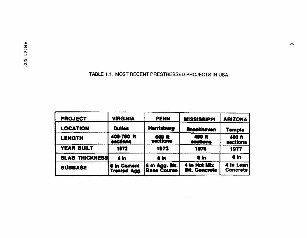
During the 1970's, new ideas were incorporated on several experimental projects
conducted in the USA. These projects include a service road at the Dulles International Airport
in Virginia (Ref 8) and three full-scale highway projects in Pennsylvania (Ref 9).
Mississippi (Ref 10). and Arizona (Ref 11). Table 1.1 summarizes some of the features of
these demonstration programs.
The Portland Cement Association in 1983 developed a computer program called PCP as
described in the report FHWAlRD-82/091 (Ref 58) which differs from the program
RR401-3/01

5
described in the present study in several respects. The program developed herein is called
PSCP1 to avoid confusion with the PCA program. The research report FHWNRD-82/169
describes the performance of prestressed pavements in as observed in four states (Ref 59).
CTR RESEARCH PROJECTS ON PCP
In order to investigate the potential of prestressed pavements, the Texas State
Department of Highways and Public Transportation (SDHPT) and the Federal Highway
Administration (FHWA) sponsored the planning and design of two prestressed overlay
projects, of one mile each, on Interstate Highway 35 in Cooke and McLennan Counties, Texas.
The projects were conducted by the Center for Transportation Research of The University of
Texas at Austin and were designated Projects 555 and 556, respectively. The work plan for
both demonstration projects consisted of four distinct phases: (1) design, {2} construction,
{3} monitoring, and (4) reporting. The design step was to encompass the latest procedures in
pavement design and technology. Project 556 in Daleiden County was constructed between
September and November 1985, whereas the construction of Project 555 was cancelled due
to cost; it was considered that it might not provide additional valuable information given its
similarity with Project 556.
The development of a design manual for PCP is also being conducted at the CTR under
401. The design manual is to be developed from design recommendations proposed in the
literature complemented with the experience gained from the McLennan County Project.
OBJECTIVES OF THE STUDY
The primary objective of this study is to develop several aspects of a rational design
procedure for prestressed pavements. The achievement of this study objective requires the
following tasks:
(1 ) Review the available literature on design of PCP to determine the variables that
are relevant to the design of slab length, joint details, thickness, and prestress
level in longitudinal and transverse directions.
RR401-3/01
J] J] ~ o .....
I
(,.) ...... o .....
(J')
TABLE 1.1. MOST RECENT PRESTRESSED PROJECTS IN USA
PROJECT VIRGINIA PENN MISSISSIPPI ARIZONA
LOCATION DulIN ............ IIroeIchaven Temple
L.NGTH ~!IO It .=:. 410ft 400ft •• DII •• uctlona
YEAR BUILT 1172 11n 1.,. 1177
SLAB THtCKNES8 lin lin lin 81n
SUBBASE lin Celnent 6In~ ... 41n Hot IIIx 41n Le.n Tr.ted A •• a... .. RConcn .. Concrete
7
( 2 ) Develop a computer program for accurately predicting the effects of several
environmental factors on the pavement structure.
( 3 ) Develop a rational approach for determining the transverse joint spacing.
( 4) Develop methods for accurately predicting the post-tensioning stress level at
midlength of the slabs.
( 5 ) Develop design procedures which accurately reflect the relationship between
level of longitudinal prestress and required pavement thickness.
( 6 ) Develop recommendations with regard to time of placement and application of
prestress forces.
( 7) Develop a procedure for determining the required level of transverse
prestress.
Objectives 3, 4, 5, and 6 represent applications of the computer program. Objective 7
is a particular case of Objective 5 since the design of the transverse prestress follows the
same principles as the design of the prestress in the longitudinal direction. The difference is
that the frictional resistance is almost negligible in the transverse direction, thus resulting
in a slight modification of the design criteria.
SCOPE OF THE STUDY
The design procedure presented in this study considers only the individual type of slabs
in which the amount of prestress, except for the effects of subgrade friction, remains
nearly constant since expansion is permitted at the joints. In the continuous type of slabs.
which require the use of jacks and abutments at the ends, after the jack gaps are filled the
slabs cannot expand freely and so the stresses vary with moisture and temperature changes.
The result is that it is difficult to predict the amount of initial prestressing necessary to
produce the desired residual stress in the concrete.
To achieve the goals of this study, the various chapters described below are presented.
Chapter 2 presents a detailed description of the important variables affecting the
deSign aspects covered in this study.
Chapter 3 presents a discussion of the frictional resistance under rigid pavements that
allows subsequent development of mathematical models.
RR401-3/01

8
The development of a model that predicts the generation of friction stresses under the
temperature variations of the thermal daily cycle is discussed in Chapter 4.
In Chapter 5, some theoretical aspects dealing with the effect of the prestress force on
the stress condition and movements of the slab are presented. Shrinkage, creep, and strand
relaxation, which are the sources of long term prestress loss, are discussed.
Chapter 6 is devoted to describing the primary features of computer program PSCP1,
the meaning of all data, and the input variables, and interpretation of the program output.
Chapter 7 presents a comparison of predictions from PSCP1 against field data recorded
at the McLennan County Project.
Several applications of the computer program in connection with the design variables
considered in this study are discussed in Chapter 8.
Chapter 9 provides a summary of the main accomplishments of this research, and the
conclusions stemming from this study, and makes recommendations ·for improvements of the
design methods by including other relevant effects.
RR401-3/01

CHAPTER 2. FACTORS TO CONSIDER IN THE DESIGN OF pcp STRUCTURAL ELEMENTS
This chapter presents a brief description of the factors that affect the following
elements of a PCP structure: slab length, pavement joints, prestress level, concrete
thickness, and prestressing steel. If the variables affecting these elements can be correlated
in all possible combinations of their magnitude, duration, and coincidence of occurrence, it
would be possible to predict their effects upon the pavement elements and produce an ideal
design. First, the factors affecting slab length are described; then, the effect of environmental
changes is discussed as they are relevant to the design of thickness and prestress forces.
SLAB LENGTH
Slab length is a function of several variables including expected joint width, prestress
applied at the ends of the slabs, subgrade friction restraint, and the desired minimum
prestress for the midlength location. However, the governing criterion for selecting the
length of PCP slabs is maximum joint width. The joints should not open under extreme
conditions more than four inches. If wider joint openings are allowed, a traffic hazard may
arise and a problem with the riding quality. Also, the seals may be damaged and eventually
pulled out of the jOints.
Factors Affecting Joint Movements
The factors that affect the longitudinal movements of the long PCP slabs are
( 1 ) Temperature Changes. These can be dassified as
( a) daily temperature variations, and
( b) seasonal temperature variations.
RR401-3/02 9

10
( 2 ) MQisture Changes. These cQnsist Qf
( a) concrete shrinkage, and
( b ) swelling produced by the change in moisture CQntent in the concrete
between seaSQns of the year (winter as related to spring).
( 3 ) Slab contractiQns produced by the application of prestress forces. These
include
(a) elastic shortening, and
( b) concrete creep under sustained load.
To accomplish the objectives of the study, a procedure to compute joint movements at any time
must be developed. In this study, all factors contributing to joint movements are included
except concrete swelling, which is a time dependent variable difficult to evaluate. Research by
Friberg on prestressed concrete for pavements indicates that the amount of seasonal swelling
is independent of the amount of prestress and is not less than 100 microstrains (Ref 2).
However, seasonal swelling varies with atmospheric conditions, such as humidity and rainfall,
and may also depend on the underlying SQiI type as well as capillary action and the depth of
the water table. Further research Is required in this area. Meanwhile, since swelling
represents reduction of the joint width, its exclusion provides some degree of conservatism
when slab length is selected.
The Effect of the Frictional Resistance
The joint movements of PCP are the result of slab length changes. Length changes of
PCP slabs may occur restrained and unrestrained by the friction. Long prestressed and
conventionally reinforced pavements have been explored in this respect in recent years.
Excellent data on movements have been obtained. In a 1312·foot prestressed pavement in
Germany (Ref 12), it was observed that the central portion of the pavement was fully
restrained by the friction for daily temperature changes, as illustrated in Fig 2.1. Cashell and
Benham (Ref 13) report daily temperature changes restrained by the friction in a 1310-foot
continuously reinforced pavement (CRCP), but not for seasonal temperature changes as shown
RR401-3/02

lJ lJ .c:.. o .....
I
(.oJ ...... o N
c ~ -c
CD E CD > 0 :E
ct 1312' (400m)
~~OOOOO7
\ \ 's .3 .. •
I '7 •
.2 I Daily Change in i
.1 Length for 20Of. I •
0 0 1 2 3 4 5 6 6 5 4 3 2 1 0
Distance from Ends, 100's ft
Fig 2.1. Restrained temperature expansion in 1312-feet prestressed slab in Viernheim, Germany, for a 20°F temperature increase from 5:45 AM to 5:25 PM (Ref 12).
6 5 4 3 2 1 0
E E -c CD E CD > 0 :E

12
in Fig 2.2. The daily movements of the CRCP were smaller than for the prestressed slabs due
to the internal relief provided by the cracks of the CRCP. The large and even movements due to
seasonal influences in the CRCP corresponded closely to contraction or expansion without
frictional resistance.
Summarizing. the slab movements can be classified with respect to the frictional
resistance as follows:
( 1 ) Movements partially restrained by the friction. This category includes the
movements produced by the daily temperature changes.
(2) Movements unrestrained by the friction. These movements include concrete
swelling, shrinkage and creep, and
(3 ) A third classifjcation type is reQuired for elastic shortening which is
diminished by the frictjon when the prestress force ;s applied. but which
affects the full slab length shortly after prestressing (8ef 43). These
movements are, in essence, temporarily restrained movements.
Effect Qf the prestressing TechniQye
In connection with maximum joint opening, the selection of prestressing technique and
type of joint plays an important role. The slabs may be prestressed in short gaps left between
the slabs, from 6 to 8 feet long, or in blockouts or stressing pockets at the center which are
filled with concrete after the prestress force has been applied.
Gap Slabs. If the stressing is done in the gaps, the gaps should be left open for some
time period to permit most of the progressive length changes to occur, including elastic
shortening, shrinkage, and creep, and then filled with a concrete filler slab. Therefore. the
use of gap slabs has the advantage that the increase in width of the joints after placement of the
gap concrete is reduced and generally longer slabs can be constructed.
Gap slabs may be constructed in double and single joint configurations. The double
joint configuration consists usually of a reinforced slab with two joints, one at each end of the
gap slab, as shown in Fig 2.3 (Refs 23 and 60). Since the gap slab is not prestressed, it
should be thicker than the PCP. This configuration has the advantage of having less movement
at each joint, approximately half the movement of a single joint. The main disadvantage is
R8401-3/02
:D :D .,.. o ..... , (.) ...... o N
Seasonal Change in Length for 45- F: Seasonal for 450f'---,.
. c -.s:::. ...
C) c 4D ..J -as J: .s:::. 0 as w c .-... c 4D E 4D > 0
:::E
. 7
.6
.5
.4
.3
.2
.1
< Actual
~
Daily Change in Length for
200f'
<t I • I • 1310'
~' ~/ <§S/ ./ /
/
o I , :::=r- .. _ .... _J.b_adn ... -+_ ... -.......,.-= «
01234566543210
Distance from Ends, 100's ft
Fig 2.2. Restrained daily expansion and unrestrained seasonal movement for 1310-foot-long CRCP (Ref 13). ~
w
:0 :0 .t>o ......
I
W -o I\)
~ Active Joint ... _
Active Joint ....,.~
Gap Slab
/
",
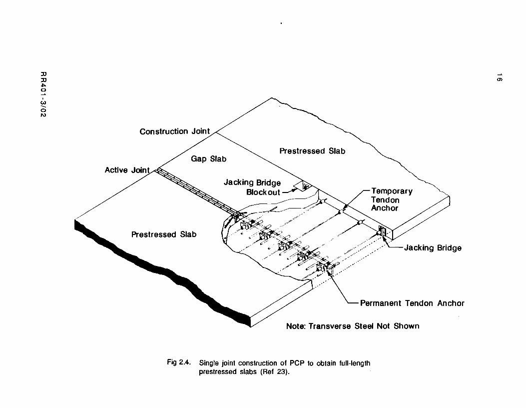
Fig 2.3. Double joint prestressed pavement construction. Reinforced gap slab placed after final post-tensioning of main prestressed slabs (Ref 23).
.t>-
15
economics. Since joints are first cost items which require periodic maintenance. both the
initial and long term costs associated with a gap slab arrangement having two joints are
greater than for a design requiring only a single joint.
Single joint configurations can be obtained for gap slabs if the tendon forces applied to
the prestressed slabs are transferred later to permanent anchors in the gap slabs at the joints
(see Fig 2.4). The stress transfer process requires special jacks and tensioning provisions at
the joint. Since the gap slab is prestressed. it requires less steel. The single joint
configuration results in fewer joints but the joints will open approximately twice as much as
a single joint with the double joint configuration. For this reason, its use is limited to
relatively short slab lengths and concretes with low thermal coefficients.
The Construction Technology Laboratories of the Portland Cement Association (Ref 23)
have proposed several designs for double and single joint gap slab arrangements. Two of these
are shown in Figs 2.3 and 2.4.
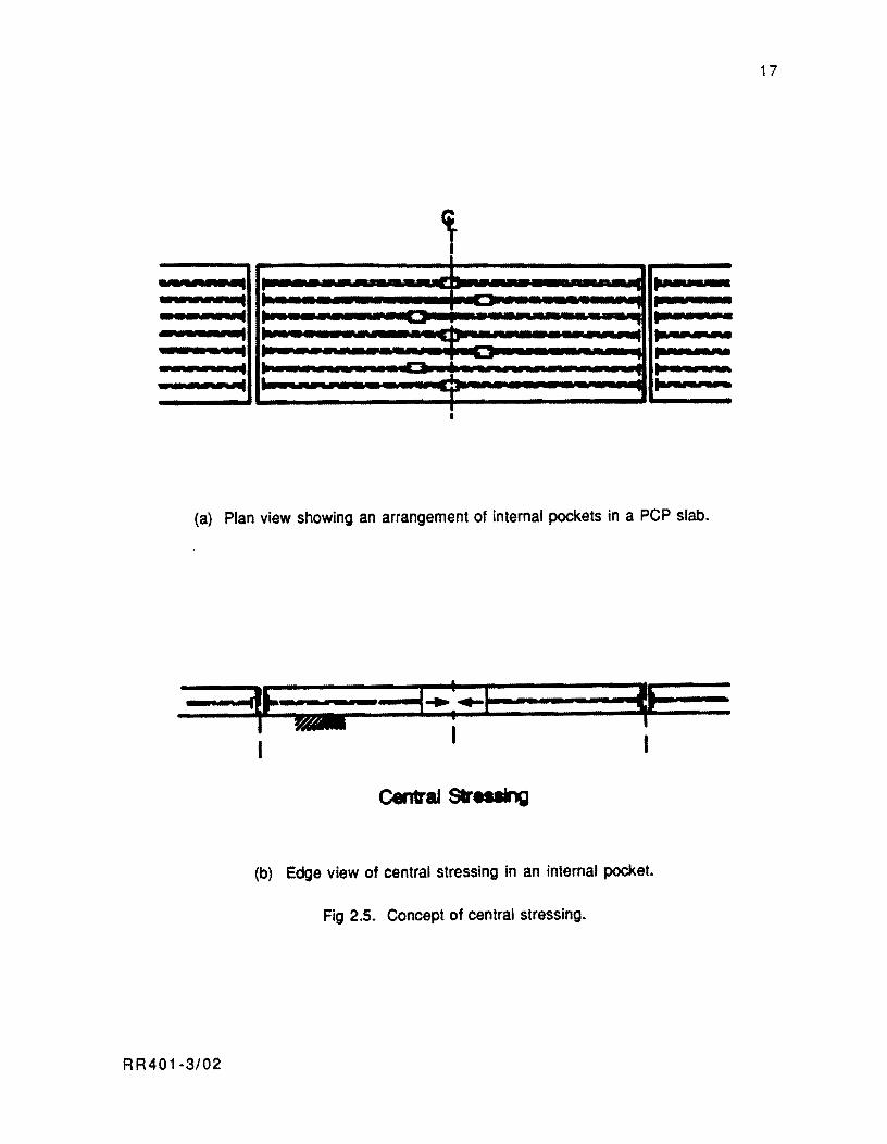
Central Stressing. Since poor gap slab performance (Le., warping. curling. rocking.
etc.) has been observed on several experimental prestressed projects. one of the objectives of
Project 401 was to find another method of post-tensioning which would eliminate gap slabs.
The most promising alternative was central stressing. Central stressing is a procedure in
which the strands are stressed in internal pockets. The concept is illustrated in Fig 2.5. For
a series of different schemes of central stressing the reader is referred to a series of field
tests conducted near Valley View, Texas. by the staff of CTR Project 401 (Ref 34). The main
disadvantage of central stressing in terms of joint openings is that the final joint width will
include all the elastic shortening, shrinkage. and creep; therefore. its use is suited to shorter
slabs than those that may be obtained if gap slabs are used. This does not mean that central
stressing will bring about a larger number of joints than when gap slabs are used since gap
slabs require two consecutive joints for each long PCP slab.
JOINT DESIGN
The joint width plays an essential role in the design of the joints of prestressed
pavement slabs. The joints of prestressed pavements experience openings which are
comparable to the openings of bridge joints. Therefore. the design of the joint should follow
the majority of the ACI Committee 504 recommendations (Ref 14). The use of dowels is
R R401-3/02
JJ JJ ~ o ......
I
t.) ....... o N
Prestressed Slab
Prestressed Slab
,.. .-/
Temporary Tendon Anchor
--Jacking Bridge
Permanent Tendon Anchor
Note: Transverse Steel Not Shown
Fig 2.4. Single joint construction of PCP to obtain full-length prestressed slabs (Ref 23).
m
17
q~
..... ... ....... it • ............. - .....-.. ........... - ..... ....
........ ·1 --~ .............. ........... ...-------............. I .. ~
.. ... .. ........... .... !"'" ....., ~ ...
(a) Plan view showing an arrangement of internal pockets in a PCP slab.
____ ... _·_~:: ... --,-.. 3--:-1 -==1 I
(b) Edge view of central stressing in an internal pocket.
Fig 2.5. Concept of central stressing.
RR401·3/02
18
essential for load transfer across the joints and to prevent excessive deflections of the thin
PCP slabs under heavy weight traffic. Mendoza et al (Ref 4) and Cable et al (Ref 5) presented
a review of joint details used with previous PCP projects in the USA, along with the design
details for the Texas Project. Also the PCA report FHWAlRD-821090 "Prestressed Concrete
Pavement, Volume 1, Joint Design," (June 1983) is another source of reference for this
subject.
EFFECT OF ENVIRONMENTAL CHANGES ON THE PAVEMENT STRUCTURE
Environmental variables cause time dependent variations in the net prestress level
longitudinally and vertically in a PCP. Factors producing stresses are
(1 ) Temperature and moisture stresses due to subbase friction resistance.
(2) Restrained curling produced by temperature differentials from top to bottom of
the slabs.
(3) Restrained warping produced by top to bottom moisture differential.
After the prestress forces are applied, long term slab movements may cause significant
variations of the prestress level.
Friction Restraint Stresses
As was said earlier, friction restraint stresses are produced in the slab as a result of
the daily temperature change movements. Research at the Bureau of Public Roads (Ref 18)
established that the frictional resistance is not constant, but increases with slab movement,
rapidly at first and then at a decreasing rate with increase in movement until a maximum
value is reached. This maximum value corresponds to the force required to produce free
sliding (Ref 19) For pavement slabs, the magnitude of the movements produced by a daily
temperature cycle depends on the location along the slab length. The movements normally
vary from a maximum at the edge to a minimum at the center. Therefore, the maximum
friction forces develop at the ends and decrease toward the center. Concrete stresses which
are the result of the accumulation of friction forces grow from the end toward the center. Fig
RR401-3/02
19
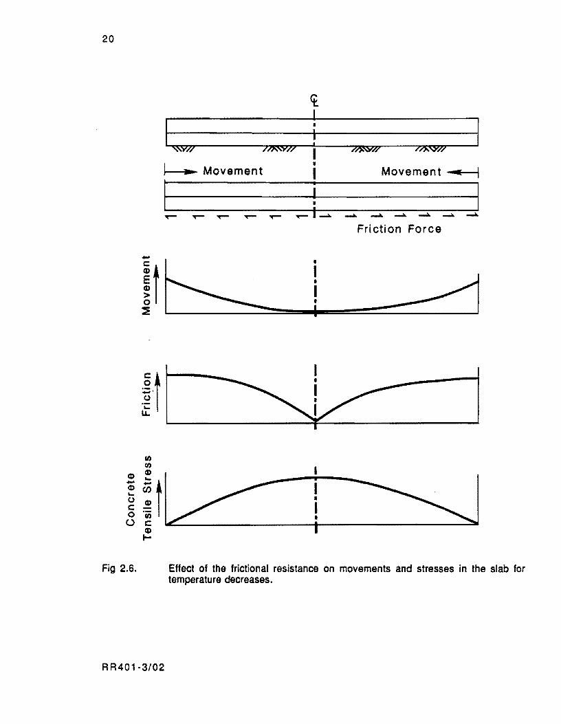
2.6 shows the profiles of movements, friction forces. and concrete stresses which are
characteristics of temperature related movements.
Studies by Friberg and Stott (Refs 20 and 21) clearly show the inelastic nature of the
friction forces developing beneath long pavement slabs. Reversals of movements result in
reversals of friction forces and corresponding concrete stresses. Characteristically, in a
daily cycle, two movement and friction resistance reversals take place. a few degrees after the
maximum and minimum slabs temperatures occur. Tensile stresses. as shown in Fig 2.6,
develop several hours after the afternoon peak, and compressive stresses with opposite
profiles than the ones shown in Fig 2.6 develop after the morning minimum temperature. The
magnitude of the friction restraint stresses depends primarily on the concrete coefficients of
contraction and expansion, the concrete modulus of elasticity, and the friction force versus
movement relationship. The tensile stresses are the most important since they result in two
unfavorable conditions for the PCP:
( 1 ) Before application of prestress forces, the tensile stresses produced on long
slabs, especially during the first night if constructed at high temperatures.
may cause premature cracking of the slabs. For this reason, the recommended
practice is to apply an initial amount of prestress during the first night to keep
tensile stresses below the concrete tensile strength and avoid first night
cracking.
( 2 ) After the application of prestress forces, the friction forces arising with
temperature drops diminish the prestress applied at the ends to a specific level.
After the application of a certain amount of force, the stress level at any section
is the super position of the external prestress force on the profile of friction
restraint stresses due to daily temperature changes. The final stresses on the
concrete are the mirror image of the friction restraint stresses before the
prestress force is superimposed. Therefore, it is at the center of the slabs that
the frictional restraint reduces the effectiveness of the external prestress
more when the temperature drops.
RR401-3/02
20
.~ t -' (J ... LL.
(I) (I)
CD CD - it CD ... (J
c: 0 U c:
CD I-
Fig 2.6.
~v/I 7/XW// I • ]--....; ........ Movement I Movement..... I
Friction Force
I • I •
Effect of the frictional resistance on movements and stresses in the slab for temperature decreases.
RR401-3/02
21
Stresses Due to Temperature Gradient
The curling of panel corners due to fluctuating air temperature and the resulting
temperature differential was measured at the AASHO Road Test (Ref 17). However, the
occurrence of curling deflections has been recognized since 1935 when Teller and Sutherland
(Ref 18) measured the deflections at pavement corners, ends, and edges caused by
temperature gradients from top to bottom. Curling occurs because concrete is a relatively
slow conductor of heat, and a temperature differential is created by the lag in time required
for heat to transfer through the slab. In a typical daily cycle, a pavement slab will curl
downward during the day, creating tensile stresses in the bottom, and upward during the night,
leading to bottom compressive stresses. These stresses are larger in the slab interior, where
the deflections are fully restrained. Also, curling stresses may be larger during the summer
months, when air temperature fluctuations are greater.
Stresses Due to Moisture Differential
An important characteristic of concrete pavement evolves from the fact that water
evaporates freely from the top surface of the pavement while the bottom surface remains
almost saturated. This effect was observed by Friberg in tests with short pavement slabs at
Rolla (Ref 2). In these experiments, the slabs showed bottom portions near full saturation,
whereas the top portions were at a lower moisture content most of the time. In PCP slabs, this
effect is magnified since the movement of water from the bottom upwards is particularly
restricted by the membrane sheets on which these slabs are cast (Ref 24). This moisture
differential tends to induce warping deformations which are fully restrained by the slab
weight in the inner zone of the longer PCP slabs. The warping restraint stresses away from
the slab end produce compressive stresses at the bottom, introducing a beneficial factor for
the pavement in resisting wheel loads. Although values of moisture differential stresses have
been recognized at different concrete ages and climatological seasons and design
recommendations have been developed in this regard, these values are not used generally.
Moisture differential depends on local environmental conditions, thus becoming difficult to
quantify with any degree of reliability. For these reasons, designers do not normally consider
warping stresses in the deSign.
RR401-3/02
22
Variations of the prestress Level
The prestress stresses may fluctuate around some average stress based on initial total
elongation of the strands, adjusted for long term concrete length changes and steel stress
relaxation. The long term slab movements, which occur without frictional resistance, produce
the most significant length variations of the PCP slabs. Therefore, long term slab movements
affect the elongation of the strands and the fluctuations of the prestress force. Seasonal
temperature variations, shrinkage and creep occurring after application of the post
tensioning force are then the time dependent variables to consider in this case.
Although relaxation of the prestressing steel and the friction between the tendons and
their conduits are not environmental variables, they are also factors affecting the prestress
level. Steel strand relaxation is a time dependent effect usually greater at the slab ends where
the steel stress is higher. The strand friction effects, which cause prestress losses usually
referred to as wobble losses. Regardless of the location of initial post-tensioning, the strand
friction will not be noticeable in pavement slabs after the first few years (Ref 1). In this
study an tnitial tension plus the close spacing of chairs assures that very little wobble was
possible in the tendons. Wobble losses can be minimized by keeping the conduit as straight as
possible during construction of the PCP.
Distribution of prestress
It was noted previously that warping and bottom compressive stresses are the result of
moisture differentials between tops and bottoms of PCP slabs. In addition, the difference in
moisture results in variations through the slab thickness of the modulus of elasticity and
creep of concrete. As a result of these variations, which are time dependent, the
precompression applied on the PCP slabs concentrates at the bottom of the pavement. This
important characteristic of PCP is rarely considered in the design. Sargious and Ghali (Ref
25) present a method of analysis to calculate the distribution of concrete stresses considering
moisture effects. However, the use of this method is limited to the knowledge of certain time
dependent parameters related to the concrete properties, such as shrinkage and creep
gradients. which are not available in the literature and which can be obtained only by site
measurements or field research on actual pavements. The favorable effect of the restrained
R R40 1-3/02
23
warping and the distribution of prestress through the pavement depth will be overlooked in
this study considering that, if ignored. an additional safety factor in the design is provided.
THICKNESS AND LEVEL OF PRESTRESS
The selection of pavement thickness and the amount of prestressing steel are variables
which have to be defined jointly. Sargious proposes the following fundamental equation for
designing the thickness and prestress of PCP based on stresses in the elastic range (Refs 15
and 16):
ft + fp = fc + w + fF + fl (2.1 )
where
fc+w = restraint stress due to temperature and moisture gradient, i.e.,
curling and warping;
fF = restraint stress due to friction;
fl = flexural stress due to imposed load;
ft = allowable concrete flexural stress; and
fp = compression due to prestress.
The use of this equation is found particularly suitable by most designers for its Simplicity and
because prestressing assures the concrete elastic behavior by raising the stress level against
cracking. This equation permits solutions for allowable loads, thickness and level of
pavement compressive stress. The prestress levels defined from this equation should be
compensated for losses due to shrinkage, creep, relaxation, friction between the conduit and
the tendon, seating losses and elastic shortening. For prestressed pavements with long joint
spacings and concomitant extensive elongation of the steel tendons. the losses due to seating and
elastic shortening are insignificant and may be ignored.
Curling, warping, and friction restraint stresses in Eq 2.1 have already been
discussed. Wheel load stresses, allowable concrete flexural stress, and prestress forces are
discussed in the following sections.
R R401·3/02

24
Wheel Load Stresses
Load stresses in the pavement can be calculated by using the well-known Westergaard
equations (Ref 27). one of the computer codes to predict stresses from plate theory (Ref 28),
multi-layered elastic theory (Ref 29). or any of the more recently developed finite element
programs (Ref 30). The advantage of multi-layered elastic theory and finite element
programs is that they can analyze the PCP slabs as a system of layers rather than relying on
an adjusted "kIt value as required when using the Westergaard equations or the plate theory
programs. In the design of PCP for highways, edge loading is the most critical load placement
for pavements without concrete shoulders, and interior loading may be considered for
pavements in which the PCP extends to the shoulder areas. The critical load for interstate
highways may be the maximum allowable 20-kip equivalent single axle load. The critical
stress location is the slab midlength where tensile wheel load stresses and environmental
stresses are additive.
Allowable Concrete Flexural Stress
The allowable concrete flexural stress in the concrete is the flexural strength divided
by a safety factor. Efforts by Klieger (Ref 17) indicate that flexural strength increases
rapidly during the first 28 days at which time it reaches 70 percent of its maximum. The
maximum strength is reached at approximately 3 months to 1 year. depending on the type of
cement used. The 28-day value is suggested for design and can be obtained from the well
known flexural strength test (Ref 26). With respect to safety factors, Report 3 of ACI
Committee 325 (Ref 1) suggests 1.5 and 2.0 as reasonable values for secondary and primary
highways respectively. The use of statistical data and the application of reliability concepts
and confidence levels is another alternative for defining safety factors for design (Ref 47).
prestress Force in the Longitudinal pirection
In the process of designing thickness and longitudinal prestress force. Eq 2.1 must be
solved for the location where. for a certain time of day and season, environmental stresses
RR401-3/02
25
combined with wheel load stresses result in a critical condition. In highway PCP slabs, the
typical conditions to check for design of longitudinal prestress are:
( 1 ) The slab midlength where the prestressed force superimposed on the profile of
tensile frictional stresses gives the minimum posHensioning level. The
critical season to check may be the summer when the fluctuations of air
temperature are larger. However, this depends on the climatological conditions
of the location of the section being designed. The critical time of the day may be
between 6 AM and 8 AM when the tensile friction stresses are near their
maximum value with a minimum of curling restraint stresses (Ref 31). Also,
because the top surface of the pavement is relatively wet at this time of the day,
the warping restraint stresses provide the least precompression at the bottom
of the slab.
( 2 ) The slab midlength where the maximum tensile stress at the bottom of the slab
due to traffic combined with the curling restraint stresses with a minimum of
friction restraint stresses create a critical condition between 4 PM and 6 PM
during the summer, when the fluctuations of air temperature produce higher
curling stresses (Ref 31).
Other criteria that must be satisfied for the elastic design of PCP in the longitudinal
direction are:
( 1 ) The post-tensioning force at the slab ends should not exceed an allowable
maximum to avoid damage to the concrete near the anchor zone.
(2) The selected thickness of the PCP should result in lower deflections than 0.03
inch to avoid exceeding the capacity of the supporting layer and causing a
problem of permanent deformation and creation of voids beneath the pavement
under heavy truck traffic (Ref 1). However. this is not a problem with PCP
used for overlays of existing rigid pavements given the adequate supporting
conditions provided by the existing pavement.
RR401-3/02

26
Analysis in the Transyerse Direction
In the transverse direction. the frictional resistance is minimum and the condition that
should be checked for the design of the transverse prestress is the tensile stress at the bottom
of the slab due to traffic combined with the curling restraint stress that creates a critical
condition between 2 PM and 4 PM during the summer (Ref 31).
fatigue Considerations
The argument usually advocated by many researchers of PCP (Refs 15, 16 and 44) to
recommend an elastic procedure to design thickness and prestress level over a fatigue
approach is that. since PCP is designed for no cracking, the net tensile stress due to wheel
loads over the precompression produced by the prestress is relatively small. Hence, it is
argued that fatigue is not a major factor in the design. In this study, it will be considered that
an elastic approach does not suffice to design PCP slabs, as such a method is not sensitive to
wheel load repetitions. Moreover, although the magnitude of the wheel load stresses over the
precompression of the prestress is relatively low, their cumulative effect may cause an
eventual fatigue failure. A design example presented in Chapter 8 of this report will support
clearly this· aspect. finally, it is worth noting that the most innovative design procedures
[revised AASHTO method (Ref 47), PCA method of deSign (Ref 57), etc.] are fatigue oriented.
PRESTRESSING STEEL
for PCP, it is common to use plastic·encased, grease protected. 270-K grade. 7-wire
strands with 0.6--inch nominal diameter. The use of low relaxation strands is advisable. The
tendons are normally tensioned to an allowable stress of 80 percent of the ultimate strength
of the strand and then released back to about 70 percent at the stressing end after the
anchoring is finished. The tendons should be stressed from both ends if gap slabs are used to
make more efficient use of the strand. for the same reason, in the case of central streSSing.
nearly equal forces should be applied on both strand segments to each side of the pocket.
Therefore, the pocket should be as close as possible to the center of the slab.
R R401·3/02
27
SUMMARY
In this chapter. a description of the important variables affecting PCP behavior and
several of the design aspects covered in this study have been presented.
The selection of slab length in prestressed pavements is governed by the maximum
joint width. The factors that affect joint width are the slab movements due to temperature
changes (daily and seasonal). concrete moisture changes (shrinkage and swelling), and
contraction induced by the effect of prestress forces (elastic shortening and creep). These
movements can be classified as short-term movements (due to daily temperature changes) and
long-term movements (due to seasonal temperature variations. concrete swelling. shrinkage
and creep). The short-term movements are restrained by the friction. The subbase friction
forces and corresponding slab stresses arise exclusively from these movements. The long
term movements occur unrestrained by the friction and. since their magnitude is fairly
substantial in the long term, the variations of the prestress level are primarily due to the
accumulation of these movements.
The design of thickness and prestress level is based on the prediction of slab stresses.
The following factors produce stresses in the slab: (1) subbase friction, (2) temperature
gradients through the pavement depth, (3) wheel loads, and (4) the precompression produced
by the prestress. Though usually an elastic approach considering these factors is proposed for
the thickness and prestress level design of PCP, this method is not sufficient for it is not
sensitive to the repetition of wheel load stresses. A fatigue approach is then indispensable for
design considering these variables.
R R401-3/02

!!!!!!!!!!!!!!!!!!!"#$%!&'()!*)&+',)%!'-!$-.)-.$/-'++0!1+'-2!&'()!$-!.#)!/*$($-'+3!
44!5"6!7$1*'*0!8$($.$9'.$/-!")':!

CHAPTER 3. NATURE OF THE FRICTIONAL RESISTANCE UNDER RIGID PAVEMENTS
The contraction and expansion movements of short pavement slabs during the daily
temperature cycles are not significantly reduced by the frictional resistance. However, in
long pavement slabs with fully restrained central portions, the magnitude of the concrete
friction restraint stresses is significant. The importance of these stresses in the design of
PCP slabs was raised in Chapter 2. In this chapter. a comprehensive discussion is made on the
nature of the frictional resistance. A good understanding of this phenomenon is essential for
developing mathematical models to simulate the behavior of long PCP slabs.
THE FRICTION FORCE
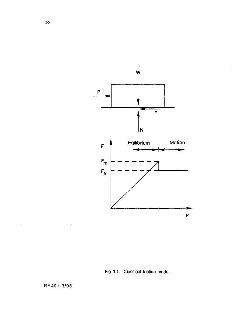
In classical mechanics, the friction force is defined as the tangential force that develops
when two surfaces which are in contact tend to move with respect to each other. The nature of
the friction force is not completely known; however, it is assumed to be produced by two
factors: (1) molecular attraction and the nature of the surfaces in contact and (2) the
irregularities between the surfaces in contact. In a block model, as shown in Fig 3.1, if a
horizontal force is applied on the block, the friction force that develops before the block
experiences any movement is called static friction force. The friction coefficient
corresponding to the maximum static friction force is named static coefficient of friction. The
friction force that develops after the maximum static friction force, Fm, is exceeded and the
block slides is named the kinetic friction force, Fk.
The friction coefficient that corresponds to the kinetic friction force is named kinetic
friction coefficient, and it is lower than the static friction coefficient. Relevant properties of
these coefficients are: (1) both coefficients are independent of the normal force. (2) both
coefficients depend on the nature of the surfaces in contact and the exact condition of the
surfaces, and (3) both coefficients are independent of the area of the surfaces in contact.
RR401-3/03 29
30
w
p -
L F
Eqilibrium Motion F ..... ... ,- ... Fm
Fk
p
Fig 3.1. Classical friction model.
RR401 ~3/03
31
FEATURES OF SLAB FRICTIONAL RESISTANCE
Studies have been conducted since 1924 to study the nature of the frictional resistance
under rigid pavement. Some of the features observed during field tests are presented below.
Goldbeck
Studies conducted in 1924 by the US Bureau of Public Roads (Ref 32) gave the first
relevant ideas on the nature of the frictional resistance offered by different materials to
horizontal movements of concrete pavement slabs. The following important conclusions may
be drawn from these studies:
( 1 ) If a pushing force is exerted on a pavement slab cast under a certain base
material, the irregularities between the surfaces in contact act as a grip for the
slab when it tends to move. This grip makes shear stresses develop at the
surface of the base material and tend to elastically deform it when the slab tends
to move. More roughness in the base results in more grip for the slab with a
consequent increase of the amount of base material pushed by the slab and,
therefore, of the frictional resistance.
( 2 ) The frictional resistance may be greatly reduced in concrete pavements if more
slippage of the slab is allowed by the elimination of ridges and depreSsion in the
base or if a sand layer is introduced between the base and the pavement.
( 3 ) Secondary observations to the interest of this research, though relevant indeed,
are that the frictional resistance is considerable lower when base materials are
tested under saturated conditions. This is due to the fact that the water acts as
. a lubricant, which permits the slabs to slip easier, and because moisture
content affects the consistency of most base materials.
After the studies conducted by Goldbeck, a thick layer of sand was introduced under
highway pavement slabs. However, in prestressed pavements, the slabs are relatively thin and
tend to experience large deformations at edges and joints of the pavement under wheel loads.
These deformations may cause voids beneath the pavement and pumping may eventually arise
RR401-3/03
32
and become a serious problem. This has led highway engineers to study other types of friction
relieving materials.
Timms
Relevant results pertaining to the behavior of friction are reported by Timms (Ref
33). His study. conducted by the US Bureau of Public Roads in 1963. consisted of pushing
concrete slabs cast on different types of materials. The following conclusions are important :
( 1 ) The friction coefficient is greater when the slabs are pushed initially and
decreases for the average of subsequent movements. Figure 3.2 shows this
condition for the materials tested.
( 2) On release of the thrusting force, the slab tends to return slightly to its
original pOSition. This sUght return. very small indeed, is a semi-elastic
recovery of the base material being tested. This particular feature is also
reported by Friberg in tests with 1 DO-foot long slabs (Ref 20).
(3) From Fig 3.2, it is evident that the lowest coefficients of friction are obtained
with double layers of polyethylene sheeting. followed by slabs placed on sand
bases, granular bases, plastic clays, and emulsified and asphalt sheet layers, in
that order consecutively.
Other Fjeld Tests
The results from other field tests that evaluate the properties of particular materials
are reported in the literature. Two of these tests are cited herein.
Saudi Arabia Tests. The apron zone of the King Fahd International Airport (KFIA) in
Dhahran, Saudi Arabia, was designed by Austin Research Engineers (Ref 31). The severe
climatological conditions in Dhahran, where large daily temperature changes are
characteristic, required that the merits of different base types be carefully assessed to avoid
premature cracking of the pavement. Concrete cylinders 22.5 inches diameter and 16 inches
deep were cast and pushed over the following materials:
RR401-3/03
s-EET ASPHALT
EMULSIFIED ASPHALT
PlASTIC SOIL
~ LAYER
o 1
First Movement
Average Subsequent Movements
2 CClEFFK)ENTOF~
3
Fig 3.2. Summary of friction coefficients obtain by Timms (Ref 33).
RR401-3/03
33
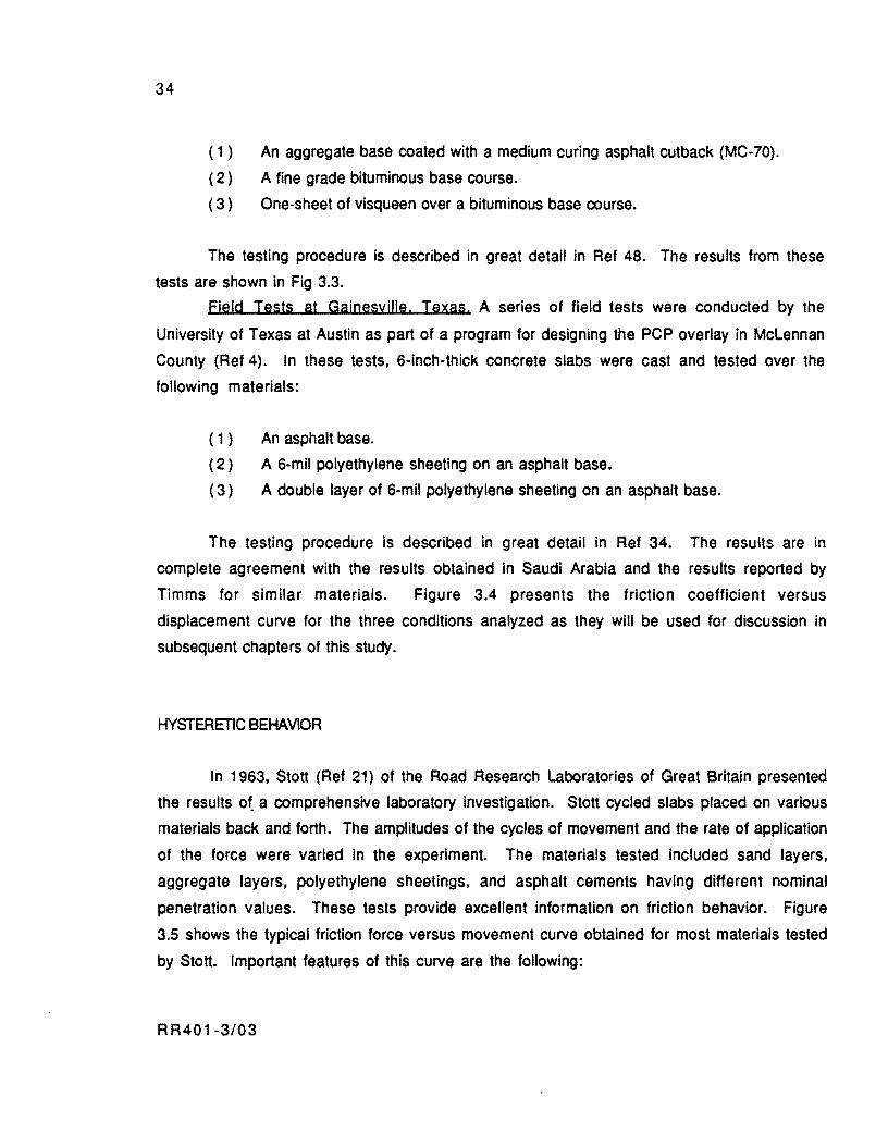
34
( 1 ) An aggregate base coated with a medium curing asphalt cutback (MC-70).
( 2 ) A fine grade bituminous base course.
( 3) One-sheet of visqueen over a bituminous base course.
The testing procedure is described in great detail in Ref 48. The results from these
tests are shown in Fig 3.3.
Fjeld Tests at Gainesville. Texas. A series of field tests were conducted by the
University of Texas at Austin as part of a program for designing the PCP overlay in McLennan
County (Ref 4). In these tests. 6-inch-thick concrete slabs were cast and tested over the
following materials:
( 1 ) An asphalt base.
(2) A 6-mil polyethylene sheeting on an asphalt base.
(3) A double layer of 6-mil polyethylene sheeting on an asphalt base.
The testing procedure is described in great detail in Ref 34. The results are in
complete agreement with the results obtained in Saudi Arabia and the results reported by
Timms for similar materials. Figure 3.4 presents the friction coefficient versus
displacement curve for the three conditions analyzed as they will be used for discussion in
subsequent chapters of this study.
HYSTERETIC BEHAVIOR
In 1963, Stott (Ref 21) of the Road Research Laboratories of Great Britain presented
the results ota comprehensive laboratory investigation. Stott cycled slabs placed on various
materials back and forth. The amplitudes of the cycles of movement and the rate of application
of the force were varied in the experiment. The materials tested included sand layers,
aggregate layers, polyethylene sheetings, and asphalt cements having different nominal
penetration values. These tests provide excellent information on friction behavior. Figure
3.5 shows the typical friction force versus movement curve obtained for most materials tested
by Stott. Important features of this curve are the following:
R R40 1-3/03
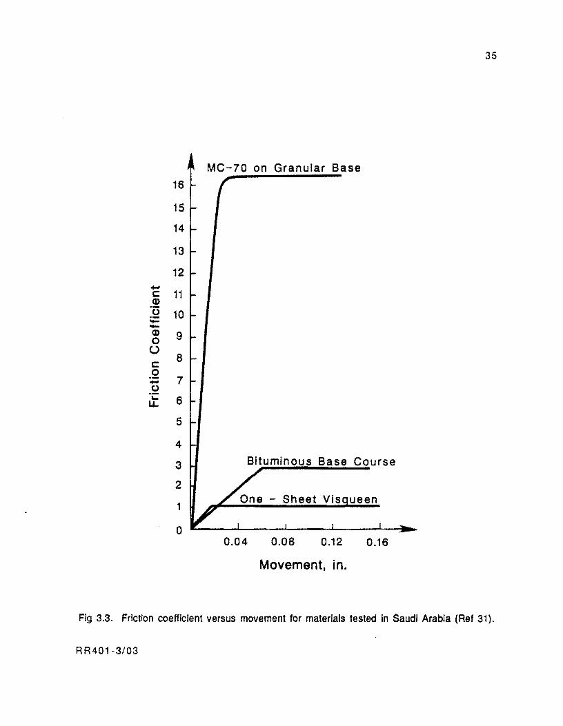
35
MC-70 on Granular Base
16
15
14
13
12 -c: 11 Q) .-0 10 ;;:: -Q) 9 0
U 8 c:
0 .- 7 -0 .-... 6 I.L
5
4
3 Bituminous Base Course
2
1
0 0.04 0.08 0.12 0.16
Movement, in.
Fig 3.3. Friction coefficient versus movement for materials tested in Saudi Arabia (Ref 31).
RR401-3/03
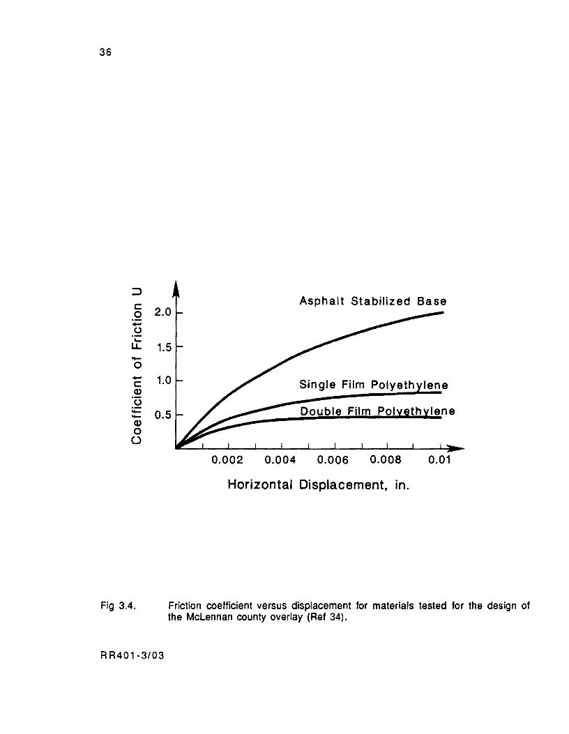
36
::::> c: 0 .... 0 ....
LL -0 .... c: Q)
0 .---Q)
0 0
Fig 3.4.
Asphalt Stabilized Base 2.0
1.5
1.0 Single Film Polyeth lene
0.5 Doubl Film Pol
0.002 0.004 0.006 0.008 0.01
Horizontal Displacement, in.
Friction coefficient versus displacement for materials tested for the design of the McLennan county overlay (Ref 34).
RR401-3/03
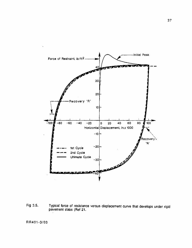
37
____ --Initial Peak Force of Restraint, Ib/ft2 --_.""'"
30
20
r----irtl--Recovery "R"
10
-100 -80 -60 -40 -20 0
Fig 3.5.
R R401·3/03
Horizontal Displacement. in.x 1000
1st Cycle
- - - 2nd Cycle Ultimate Cycle
-10
-20
R.C~ "R"
Typical force of resistance versus displacement curve that develops under rigid pavement slabs (Ref 21.
38
( 1 ) First, the force exhibits a rise until it reaches an initial peak. The friction
force that develops along this part of the curve is similar to the classical static
friction force. The peak observed in the curve is equivalent to the static
friction force from which the static friction coefficient is defined. In this zone
of the curve, most materials show a quasi-elastic behavior. If the force that
produces the movement is gradually released, the slab tends to return to its
original position as the friction force drops to zero.
( 2 ) The friction force that develops after the initial peak is similar to the kinetic
friction force of the block model in Fig 3.1. Uke the kinetic friction force, this
force remains practically constant after sliding, if further displacement of the
slab occurs. The displacements that occur after sliding are non-recoverable
when the pushing force is removed.
(3) The backward movement "R" observed in Fig 3.5 when the pushing force is
removed is a quasi-elastic recovery of the material underneath.
( 4 ) The consecutive application of cycles of displacement produces hysterectic
curves. During these cycles, the initial peak is not observed again and it is not
possible to establish a boundary between static and kinetic friction forces.
However, the resistance force resembles the static friction (with quasi-elastic
properties) in the zone where the curve is more vertical and looks like the
kinetic friction force where the curve becomes flatter. In this zone of the
curve, the slab is sliding and the movements are non-recoverable after
removal of the external force.
( 5 ) During the first few cycles of displacement. the maximum force of resistance
that develops in each cycle decreases slightly, but at the end it reaches a steady
condition. This friction force versus movement curve is probably the one that
would be encountered in practice under rigid pavements.
( 6 ) An observation irrelevant to this study though important from the standpoint of
material behavior is that asphalt cement sticks to the bottom face of the slab
and the resistance force that develops is due to viscous shear through the depth
of the material. For this reason, it is independent of slab weight and dependent
on: (a) grade, (b) thickness, (c) temperature of the bituminous layer, and (d)
rate of movement of the slab.
RR401-3/03

39
NATURE OF THE FRICTIONAL RESISTANCE UNDER RIGID PAVEMENTS
The review of tests presented above clearly shows that the relationship between
friction forces developing beneath long pavement slabs and horizontal displacements is
substantially inelastic.
The resistance force versus movement curve for most base materials placed under road
slabs is defined by two factors: (1) the elastic properties of the material beneath the slab, and
(2) the condition of the sliding plane and the nature of the materials at the interface. The first
defines the slope of the curve before sliding, and the second the maximum or kinetic friction
force obtained after the slab slides. Figure 3.6 shows the zones of the curve for each factor.
The interaction of the factors mentioned above is illustrated conceptually in Fig 3.7. If
the material beneath the slab is infinitely rigid and does not experience deformations due to
friction related shear at the interface, the force versus movement curve may look as
illustrated in Fig 3.7(a). This case may correspond to the ideal case of the block of Fig 3.1 in
which the "initial" peak has not been drawn because it disappears after a few cycles of
displacement. Figure 3.7(b), in turn, shows the curves for two materials having different
elastic properties (shear stiffnesses). The sliding plane for the case depicted in Fig 3.7(b) is
assumed to have characteristics similar to the one in Fig 3.7(a). The kinetic friction forces Fk are the same in both cases, but the point of sliding is different. Finally, Fig 3.7(c) shows
the effect of having two different sliding plane textures for the same base material. This is the
case for the rough sliding plane furnished by granular bases with and without a sand layer
provided on top of the granular base. This may also be the case for slabs cast on bituminous
materials with and without layers of polyethylene sheeting provided at the interface.
Modeling of Friction Forces
The purpose of the previous discussion is to indicate that the friction forces may be
considered elastic if sliding does not occur along the slab length. This is the case for plain
concrete and conventional reinforced concrete pavements which are typically shorter than 40
feet These slabs develop maximum movements below 0.03 inch under a normal daily cycle and
the frictional resistance that builds up is defined by the quasi-elastic properties of the base
material.
RR401-3/03
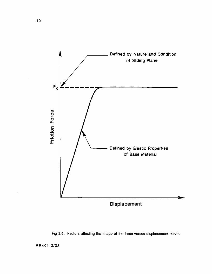
40
Q)
o r... o LL
c: .2 -o .-r... LL
".--___ Defined by Nature and Condition
of Sliding Plane
Defined by Elastic Properties of Base Material
Displacement
Fig 3.6. Factors affecting the shape of the force versus displacement curve.
RR401-3/03
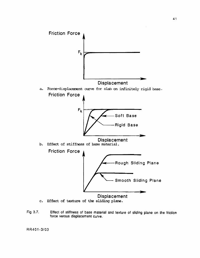
Fig 3.7.
Friction Force
Fk ~.-------------------
Displacement a. Force-displac::enEnt curve for slab on infinitely rigid base.
Friction Force
~~-Soft Base
'---Rigid Base
Displacement b. Effect of stiffness of base material.
Friction Force
~"---Rough Sliding Plane
Smooth Sliding Plane
Displacement c. Effect of texture of the sliding plane.
41
Effect of stiffness of base material and texture of sliding plane on the friction force versus displacement curve.
RR401-3/03
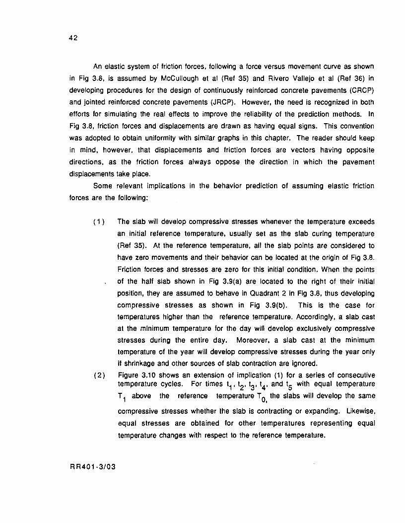
42
An elastic system of friction forces, following a force versus movement curve as shown
in Fig 3.8, is assumed by McCullough et al (Ref 35) and Rivero Vallejo et al (Ref 36) in
developing procedures for the design of continuously reinforced concrete pavements (CRCP)
and jointed reinforced concrete pavements (JRCP). However, the need is recognized in both
efforts for simulating the real effects to improve the reliability of the prediction methods. In
Fig 3.8, friction forces and displacements are drawn as having equal signs. This convention
was adopted to obtain uniformity with similar graphs in this chapter. The reader should keep
in mind, however, that displacements and friction forces are vectors having opposite
directions. as the friction forces always oppose the direction in which the pavement
displacements take place.
Some relevant implications in the behavior prediction of assuming elastic friction
forces are the following:
( 1 ) The slab will develop compressive stresses whenever the temperature exceeds
an initial reference temperature, usually set as the slab curing temperature
(Ref 35). At the reference temperature, all the slab points are considered to
have zero movements and their behavior can be located at the origin of Fig 3.8.
Friction forces and stresses are zero for this initial condition. When the points
of the half slab shown in Fig 3.9(a) are located to the right of their initial
poSition, they are assumed to behave in Quadrant 2 in Fig 3.8, thus developing
compressive stresses as shown in Fig 3.9(b). This is the case for
temperatures higher than the reference temperature. Accordingly, a slab cast
at the minimum temperature for the day will develop exclusively compressive
stresses during the entire day. Moreover, a slab cast at the minimum
temperature of the year will develop compressive stresses during the year only
if shrinkage and other sources of slab contraction are ignored.
(2) Figure 3.10 shows an extension of implication (1) for a series of consecutive temperature cycles. For times t1, t2, t3, t4, and t5 with equal temperature
RR401-3/03
T 1 above the reference temperature TO, the slabs will develop the same
compressive stresses whether the slab is contracting or expanding. Likewise,
equal stresses are obtained for other temperatures representing equal
temperature changes with respect to the reference temperature.
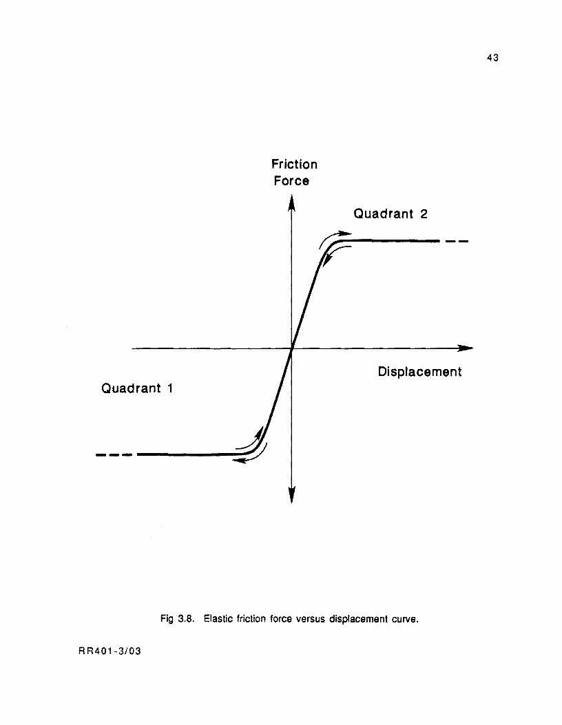
Quadrant 1
----------
Friction Force
Quadrant 2
r----
Displacement
Fig 3.B. Elastic friction force versus displacement curve.
R R401-3/03
43
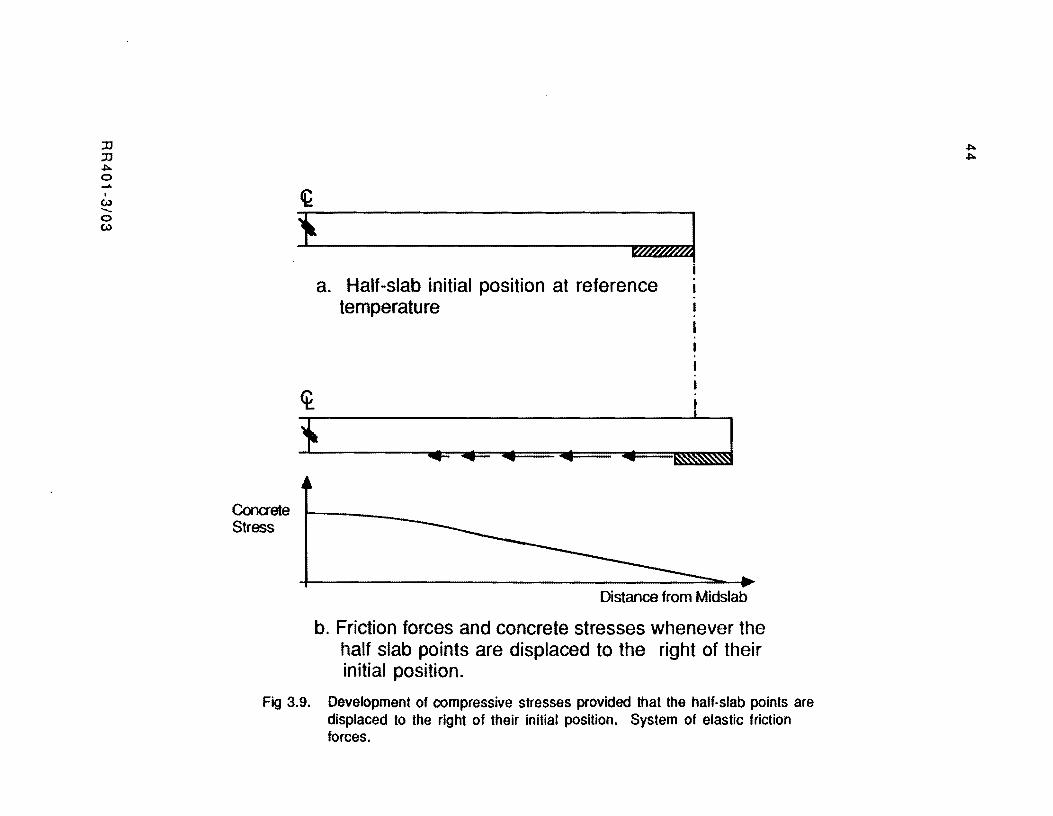
:IJ :IJ ~ o ..Jo. . (.oJ ........ o (.oJ
Conaete Stress
~ } .. _ .. _ .. _.. . ----::J
~
i a. Half-slab initial position at reference i
temperature
} -J .. 'iiII=" .... .. I&.~~ --~ ~~
Distance from Midslab
b. Friction forces and concrete stresses whenever the half slab points are displaced to the right of their initial position.
Fig 3.9. Development of compressive stresses provided that the half-slab points are displaced to the right of their initial position. System of elastic friction forces.
~ ~
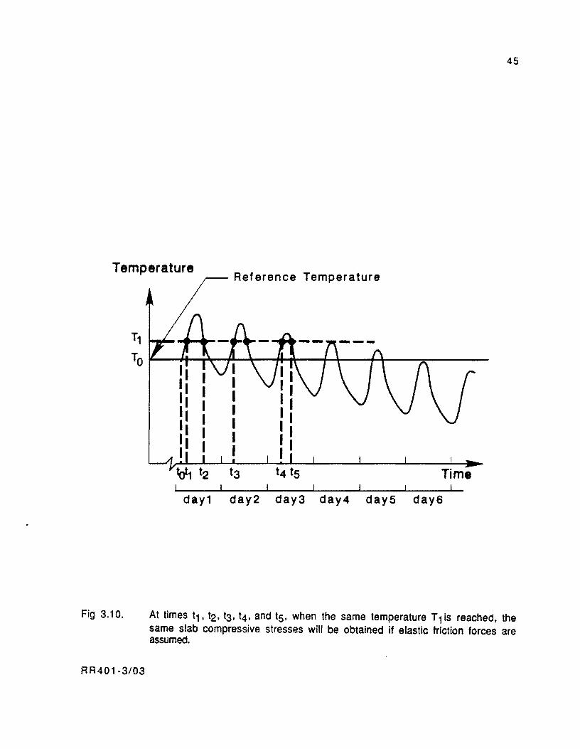
45
Temperature Reference Temperature
Fig 3.10.
T1
TO~--~~~L-~~~--~~--~~--~-------
day1 day2 day3 day4 dayS day6
At times t 1 • t2. t3, t4, and t5. when the same temperature T 1 is reached. the same slab compressive stresses will be obtained if elastic friction forces are assumed.
RR401-3/03
46
( 3 ) Shrinkage and other sources of long term longitudinal movement do not occur
without frictional resistance but accumulate on a daily rate basis, resulting
eventually in the maximum friction forces and concrete restraint stresses.
This mechanism is illustrated in Fig 3.11. If the slab starts contracting from
the maximum temperature of the day, point A in Fig 3.11 moves from its initial position, ZAO, to position ZA 1 after the maximum contraction of the day. The
part of the movement ZA1 due to the temperature drop is ZAT1 whereas the rest
of it is produced by shrinkage and other sources of long term contraction. If the temperature increases to the maximum again, point A moves to position Z A2
following the same path along the curve. The point does not return to its initial position ZAO because a small portion of long term movement has occurred. If
long term movements did not occur, point A would move between positions ZAO
and Z A 1 indefinitely.
However, the accumulation of shrinkage, etc., along with the movements
due to the daily thermal cycle results in shifts of point A along the curve between positions ZAn-1 and ZAn several days after the start of this process.
Thus, point A reaches the maximum or kinetic friction force Fk. This concept
was demonstrated for a single point; however, a similar behavior would be
observed for the rest of the slab points if elastic friction forces are assumed.
For the case of the long PCP slabs, a substantial portion of the slab works in the sliding
range due to movements produced by the daily cycle. The inelasticity of the frictional
resistance and the significant sliding of the slab points make reversals of temperature,
producing reversals of movements exceeding 0.01 to 0.02 inch, result in reversals of
frictional resistance. This is particularly true if friction reducing materials are used beneath
the slab.
The following are the implications from assuming an inelastic system of friction
forces beneath the slab:
RR401-3/03
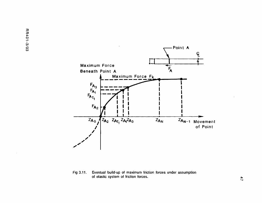
JJ JJ .... o .... . (.0) "-o (.0)
Maximum Force
Beneath Point A
:-. S; Point A It
: .. 1 t ......-fA
Maximum Force Fk ---------- ~ . FA3 FAl
FATl
FA2
ZAN
I I I I I I I
ZAN-l Movement of Point
Fig 3.11. Eventual build-up of maximum friction forces under assumption of elastic system of friction forces. ....
......
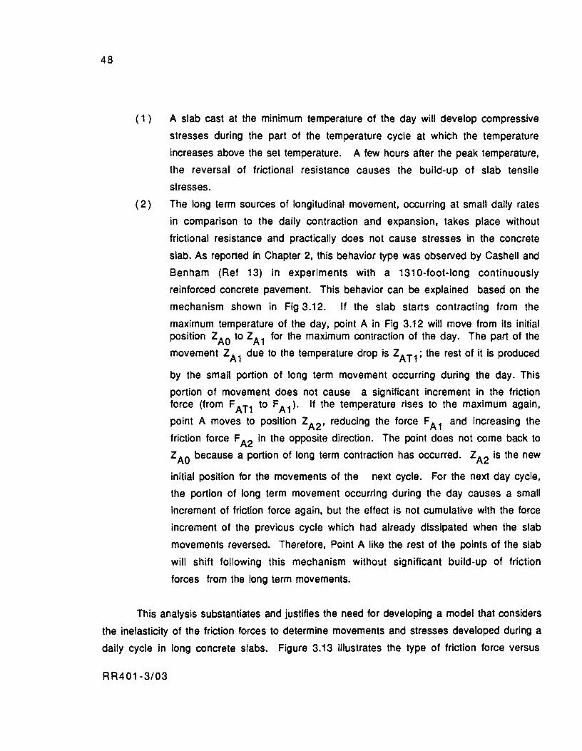
48
( 1 ) A slab cast at the minimum temperature of the day will develop compressive
stresses during the part of the temperature cycle at which the temperature
increases above the set temperature. A few hours after the peak temperature,
the reversal of frictional resistance causes the build-up of slab tensile
stresses.
(2) The long term sources of longitudinal movement, occurring at small daily rates
in comparison to the daily contraction and expansion, takes place without
frictional resistance and practically does not cause stresses in the concrete
slab. As reported in Chapter 2, this behavior type was observed by Cashell and
Benham (Ref 13) in experiments with a 1310-foot-long continuously
reinforced concrete pavement. This behavior can be explained based on the
mechanism shown in Fig 3.12. If the slab starts contracting from the
maximum temperature of the day. point A in Fig 3.12 will move from its initial position ZAO to ZA 1 for the maximum contraction of the day. The part of the
movement ZA1 due to the temperature drop is ZAT1; the rest of it is produced
by the small portion of long term movement occurring during the day. This
portion of movement does not cause a significant increment in the friction force (from F AT1 to FA 1)' If the temperature rises to the maximum again.
point A moves to position ZA2' reducing the force FA 1 and increasing the
friction force F A2 in the opposite direction. The point does not come back to
Z AO because a portion of long term contraction has occurred. ZA2 is the new
initial position for the movements of the next cycle. For the next day cycle,
the portion of long term movement occurring during the day causes a small
increment of friction force again, but the effect is not cumulative with the force
increment of the previous cycle which had already dissipated when the slab
movements reversed. Therefore, Point A like the rest of the points of the slab
will shift following this mechanism without significant build-up of friction
forces from the long term movements.
This analysis substantiates and justifies the need for developing a model that considers
the inelasticity of the friction forces to determine movements and stresses developed during a
daily cycle in long concrete slabs. Figure 3.13 illustrates the type of friction force versus
RR401-3/03
JJ JJ ~ o ..... . (.\) --o (.\)
Friction Force Ben.ath Point A----,.
FAl FAll
p~n:A2 r [J I }
FA
Fig 3.12. Shifting of point A without frictional resistance for long-term movements if an inelastic system of friction forces is assumed. ~
to
50
Friction Force
-------.... -----
Displacement
- - -1--------
Fig 3.13. Friction force versus displacement curve assumed in this study.
RR401-3/03
51
movement curve assumed in this study. Since the elastic recovery that takes place when the
forces inducing slab movements are removed is typically small for most materials used under
rigid slabs, this can be neglected. A slightly conservative prediction of movements and
stresses would then be obtained.
SUMMARY
In this chapter is a comprehensive discussion of the nature of the frictional resistance
under rigid pavements. From a review of field and laboratory tests. it is observed that the
frictional resistance is substantially inelastic with long slabs. The friction forces have, then,
to be modeled elastically in the case of the long slabs of PCP, for a substantial portion of the
slab works within the sliding zone for the movements of the daily thermal cycle. For the short
slabs of the jointed pavements the friction forces can be modeled as elastic forces, as the slab
movements due to the daily temperature variations do not exceed the sliding movement (near
0.02 in.).
It inelastic friction forces are assumed, reversals of slab movement result in
reversals of the direction of the friction forces. Accordingly, a slab cast at the minimum
temperature of the day will develop compressive stresses only during the part of the day when
the temperature increases. A few hours after reaching the peak temperature, the slab
movement reversal causes a friction force reversal and the build-up of tensile stresses in the
slab. This behavior type cannot be predicted if the friction forces are modeled elastically.
Another relevant implication of assuming inelastic friction forces is that the long term
sources of longitudinal movement (shrinkage, creep, etc.), occurring at small daily rates (as
opposed to the contraction and expansion movements of the daily cycle, which are fairly
substantial) occur practically without frictional resistance and do not cause concrete stresses.
This behavior could not be predicted if the friction forces were assumed to be elastic. If
elastic friction forces are assumed, the long term movements. usually representing
contractions, accumulate on a daily rate basis resulting in an eventual build-up of maximum
friction forces and slab stresses.
R R401-3/03

!!!!!!!!!!!!!!!!!!!"#$%!&'()!*)&+',)%!'-!$-.)-.$/-'++0!1+'-2!&'()!$-!.#)!/*$($-'+3!
44!5"6!7$1*'*0!8$($.$9'.$/-!")':!
CHAPTER 4. PROBLEM STATEMENT AND MODEL FOR FRICTION
Due to its nature, the prediction of movements and stresses as a function of time for a
PCP slab is a highly complex problem. However, it is greatly simplified by assuming that the
slab will remain uncracked during its entire life. As indicated in Chapter 2, PCP slabs are
designed elastically for non-cracking, an assumption carried throughout this study.
The inelastic modeling of friction forces requires a time incremental approach to be
adopted for predicting pavement responses during daily temperature cycles occurring at
specific periods of the pavement life. A time incremental approach is required, because the
state of stresses and deformations in the slab at a specific time is dependent on the slab
condition during the previous time increment.
The fundamental phenomenon to model in this research is stated in the following
section.
PROBLEM STATEMENT
Environmental factors are assumed in this study to start to affect the pavement
structure at the setting hour. The setting hour is defined herein as the reference time from
which the concrete can be considered to have gained enough plasticity to act as a semi.rigid
body. McCullough, Abou·Ayyash et al (Ref 35) assume that this reference time takes place
five hours after slab casting, in the design of continuously reinforced concrete pavements
(CRCP). This study develops a procedure for predicting the state of deformations and stresses
in the structure due to environmental factors (temperature, moisture, etc.) and prestress
forces at specific periods after the setting time.
A scheme illustrating the scope of the problem and the variables considered in this analysis is presented in Fig 4.1. Temperature changes and shrinkage Zc tend to cause slab
movements after the setting time (to) which induce friction forces and related stresses.
Curling deformations and stresses start occurring at time to as a result of vertical gradients
through the pavement depth. Concrete modulus of elasticity, Ec' is a time dependent property
which starts building at the setting time to' Elastic shortening, creep, and strand relaxation
start affecting the pavement structure after the first amount of prestress force P 1 is applied,
and they increase in magnitude with additional increments of (he prestress force P 2' P 3' etc.
RR401-3/04 53
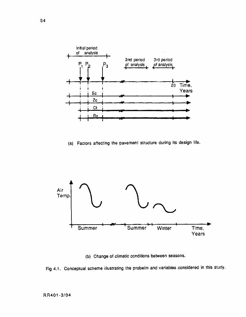
54
ln~ial period
+ of analysis
+
~1 2nd period 3rd period
r ff analysis. f' analYSis:
+ 'IIfII'- T'" 20 Ime,
Ee Years + sM' t ... J Ze
." r • ... J Ct .. SF ... +
R~ III ..
(a) Factors affecting the pavement structure during its design life.
Air Temp.
Summer Summer Winter
(b) Change of climatic conditions between seasons.
Time, Years
Fig 4.1. Conceptual scheme illustrating the probelm and variables considered in this study.
R R401 -3/04

55
The magnitudes of movements, stresses and deformations vary depending on prevailing
climatological conditions. The variation of climatological conditions is represented in Fig
4.1 (b) by shifts and changes in the shape of air temperature cycles between seasons.
Simulations of three periods has been found to be particularly important for the design
of the pavement elements considered in this study:
( 1 ) From slab setting until all post-tensioning stages have been completed -- The
simulation of this initial period permits one to analyze the movement and
stress mechanism during the first hours of life of the PCP, including the effects
of the application of prestress forces.
( 2 ) A 24-hour interval during the PCP design life when most prestress losses have
occurred and at the season when the fluctuations of ambient temperature are
largest (commonly the summer) -- The analysis of this period allows one to
obtain the critical stress combination produced by the factors considered in
this study. This critical combination is essential in the design of the PCP
thickness and prestress level.
(3) A 24-hour interval during the PCP design life when the effects of the time
dependent variables (shrinkage, creep, relaxation, etc.) have mostly occurred
-The analysis of this period allows evaluation of maximum joint opening and
minimum prestress level after losses. These variables are relevant for
deSigning slab length, pavement joints, and strand spacing.
The periods of analysis considered herein are illustrated in Figs 4.1 (a) and 4.1 (b).
Estimates of the following aspects, as a function of time, are required for each period:
( 1 ) Friction stresses and prestress. Only friction stresses if prestress forces are
not applied by the time of analysis.
(2) Cumulative slab movements since the setting time, and
( 3 ) Curling deformations and stresses.
RR401-3/04

56
General Assumptions
In order to solve the problem stated previously, several assumptions which simplify
the analysis but do not invalidate the model are necessary. The following premises will be
assumed then:
( 1 ) For the initial period of predictions. after prestress forces are applied, the
slab movements occur unrestrained by the prestress. Likewise, movements
occurring during this period do not cause significant variations of the
prestress level. This assumption permits exclusion from the analYSis of a
compatibility relationship between concrete and steel deformations. Prestress
forces are assumed to be applied instantaneously, thus only temporarily
affecting the friction forces, and then they remain constant until the end of the
analysis period. The validity of this assumption is discussed later in
Chapter 5.
( 2 ) For the second and subsequent periods of predictions, it is assumed that friction
forces develop as a result of the movements due to daily temperature changes
and independently of prestress forces and long term movements. Likewise, the
prestress level is assumed to be significantly affected by long term movements
but unaffected by daily slab movements. If the development of friction forces
and the prestress level variations are assumed to occur independently. both
mechanisms can be modeled separately and the slab responses superimposed for
computation of final movements and stresses. This assumption is valid several
hours after the prestress force is applied. Immediately after post-tensioning,
the sequence of friction force development due to temperature changes is
temporarily perturbated by the sudden contraction produced by the external
prestress force. In this time interval, an independence of occurrence cannot be
assumed.
( 3) For all analysis periods, curling stresses occur independently of other
mechanisms causing stresses in the structure. Then, responses from a curling
model can be superimposed to the responses from other models for computation
of final movements and stresses.
RR401-3/04
57
The assumptions stated above permit the analysis of pavement behavior through three
independent models: a model for friction, a curling model and a model, to account for the time
dependence of the prestress level. The primary contribution of this study is modeling the
friction mechanism assuming inelastic forces. The model for curling was adopted from the
literature (Ref 42) and implemented in this approach. The remainder of this chapter is
devoted to presenting the principles of the friction model.
FRICTION MODEL
In a temperature daily cycle, rigid pavement slabs experience two reversals of
movement. These reversals occur at the maximum and minimum temperatures of the cycle.
Away from these maximum or minimum temperatures, temperature changes cause contraction
or expansion movements and tensile or compressive stresses along the slab length. After the
afternoon peak movement reversal, the slab shortens as the concrete temperature steadily
decreases. A profile of tensile stresses due to frictional restraint is presented in Fig 4.2. A
similar situation, in the opposite direction, with compressive stresses rather than tenSile,
occurs after the morning minimum temperature reversal. In both cases, the slab segments
closer to the ends (Zone 3 in Fig 4.2) are the ones that accumulate lower restraint stresses.
The central portion (Zone 1) is typically fully restrained in long slabs and, therefore,
develops a constant stress. The first submodel for the thermal cycle should simulate exclusive
contraction or expansion movements and stresses developing along the entire slab.
The inelastic nature of the frictional resistance causes the movement reversals taking
place at the peak or the trough of the thermal cycle to also result in reversals of frictional
resistance. Likewise, these reversals of frictional resistance cause slab reversals of concrete
stress. The movement direction changes occur first near the slab ends where the friction
restraint stresses accumulated up to the peak or the trough are lower. During this transition
stage, the slab develops tensile and compressive stresses at the same time in different
locations. The dashed line in Fig 4.3 illustrates the stress condition at the morning minimum
temperature, and the continuous line the condition after the temperature has increased a few
degrees above the minimum. It is possible to complete the cycle of movement and stress
predictions if a second submodel simulates the mechanism during these movement reversal
intervals.
RR401·3/04
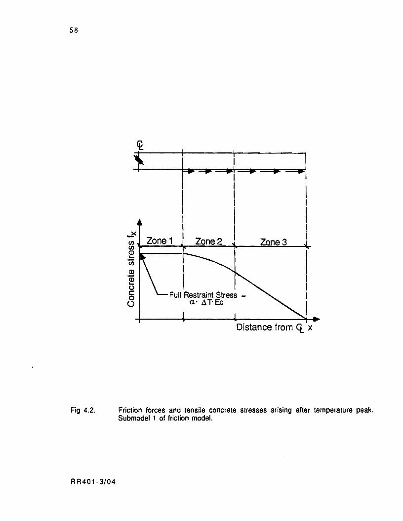
58
Fig 4.2.
R R401-3/04
$ F~-.~=+---.~ I I
I I I I . I , I . I ! I
~ I. i (/) Zone 2 (/)
~ Ir----........ ~
1n jB ~ o § Full Restraint Stress = Q (x. 6T'Ec
Distance from ct x
Friction forces and tensile concrete stresses arising after temperature peak. Submodel 1 of friction model.
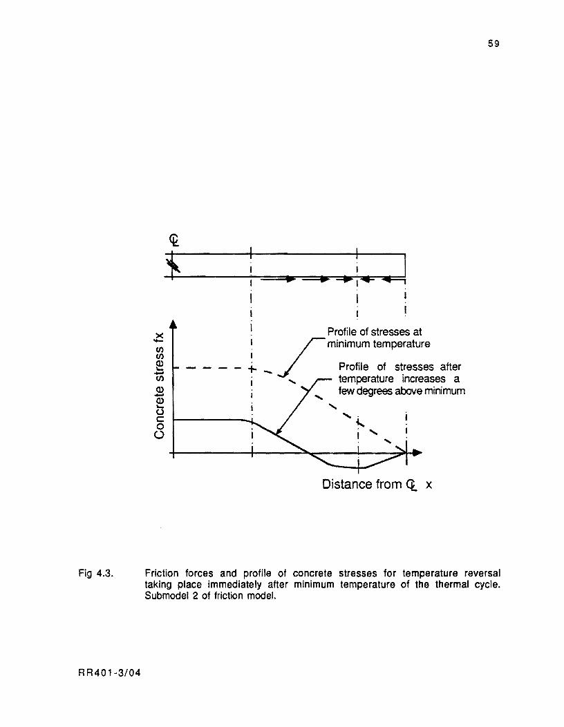
Fig 4.3.
R R40 1-3/04
x -(/) (/)
~ -(/) <l> -e (.) c: o
Q
Profile of stresses at r minimum temperature
+ _ ./ Profile of stresses after ...... temperature increases a
few degrees above minimum
......
" ......
Distance from <t x
59
Friction forces and profile of concrete stresses for temperature reversal taking place immediately after minimum temperature of the thermal cycle. Submodel 2 of friction model.

60
Assumptions of the Model
The following assumptions are made in the derivation presented herein:
( 1 ) Concrete is a homogeneous, linearly elastic material. The slab is a solid body
without discontinuities, such as cracking.
(2) The frictional resistance produced by dowels, tie bars, and lanes adjacent to the
slab longitudinal movements is neglected.
( 3 ) The friction coefficient versus displacement relationship which caracterizes
the frictional resistance under the slabs is of the type shown in Fig 3.13 in
Chapter 3.
( 4 ) The temperature variations considered in this analysis are those occurring at
the slab mid-depth. The friction stresses that develop will be considered as
evenly distributed on the cross section. As a result of this assumption, a one
dimensional analysis of an axial structural member is applicable.
(5) The redistribution of the slab weight due to curling and warping that affects the
friction forces developing beneath the slab is neglected.
( 6 ). The effect of concrete creep before application of prestress forces is also
neglected.
(7) Symmetry of conditions with respect to the geometric center of the slabs is
assumed. Therefore, the analySiS will be limited to the half slab length with
the geometric center being fixed.
( 8) The origin for slab length X in the longitudinal direction is at the midslab.
Friction forces are positive in the positive X direction. Movements in the
positive X direction are also positive. Friction forces and movements are
always of oppOSite signs. Tensile stresses in the concrete are positive. Mid
depth temperature changes are positive if they represent temperature
increments at a given time, with respect to an earlier time considered.
RR401-3/04

61
Submodel for Contraction and Expansion
The well-known finite difference technique will be applied for solution of the problem
stated herein. Therefore. it is necessary that the slab be divided into small elements for
analysis.
In order to facilitate the reader's understanding of this derivation, an initial stressless
condition will be assumed. Then, for a temperature change AT with respect to the reference
temperature, all the slab elements tend to experience the same unit deformation eX'" a • AT
in the X direction (see Fig 4.4), where ex is the concrete coefficient of thermal contraction and
expansion.
In the sequence of the occurrence of thermal cycles, an initial stressless condtion
may be assumed only for movements and stresses occurring between the setting time and the
first temperature reversal. For temperature changes after temperature reversals, the slab
elements start reversing the movement from an initial stress condition which is different for
each slab element. In this case, the elements tend to experience different unit deformations eX' Therefore, it is required that the principles presented herein be extended to cover this
situation. A detailed discussion of this aspect is provided in subsequent sections of this
chapter. If a temperature change AT occurs with respect to the setting temperature To (Fig 4.4
exemplifies a temperature drop), an element of length dX located a distance X from the
midslab, as shown in Fig 4.4(a), tends to develop a strain equal to (X • AT. Part of this strain
may be restrained by the frictional resistance, and the remainder of it occurs as a unit
deformation. The part of the strain restrained by the friction produces a stress in the
concrete. Hence, friction forces develop beneath the slab to balance the stress or force in the
concrete. The equilibrium of forces in the slab segment to the right of the element considered
can be written as
RR401-3/04
lJ2
F X = J u x • 'Y. 0 • dx X
(4.1 )
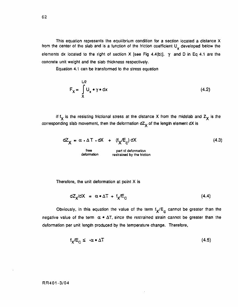
62
This equation represents the equilibrium condition for a section located a distance X from the center of the slab and is a function of the friction coefficient Ux developed below the
elements dx located to the right of section X [see Fig 4.4(b)]. 'Y and D in Eq 4.1 are the
concrete unit weight and the slab thickness respectively.
Equation 4.1 can be transformed to the stress equation
(4.2)
If fX is the resisting frictional stress at the distance X from the midslab and Zx is the
corresponding slab movement, then the deformation dZX of the length element dX is
free deformation
part of deformation restrained by the friction
Therefore, the unit deformation at point X is
(4.3)
(4.4)
Obviously, in this equation the value of the term fX/Ec cannot be greater than the
negative value of the term a. ll. T, since the restrained strain cannot be greater than the
deformation per unit length produced by the temperature change. Therefore,
(4.5)
RR401-3/04
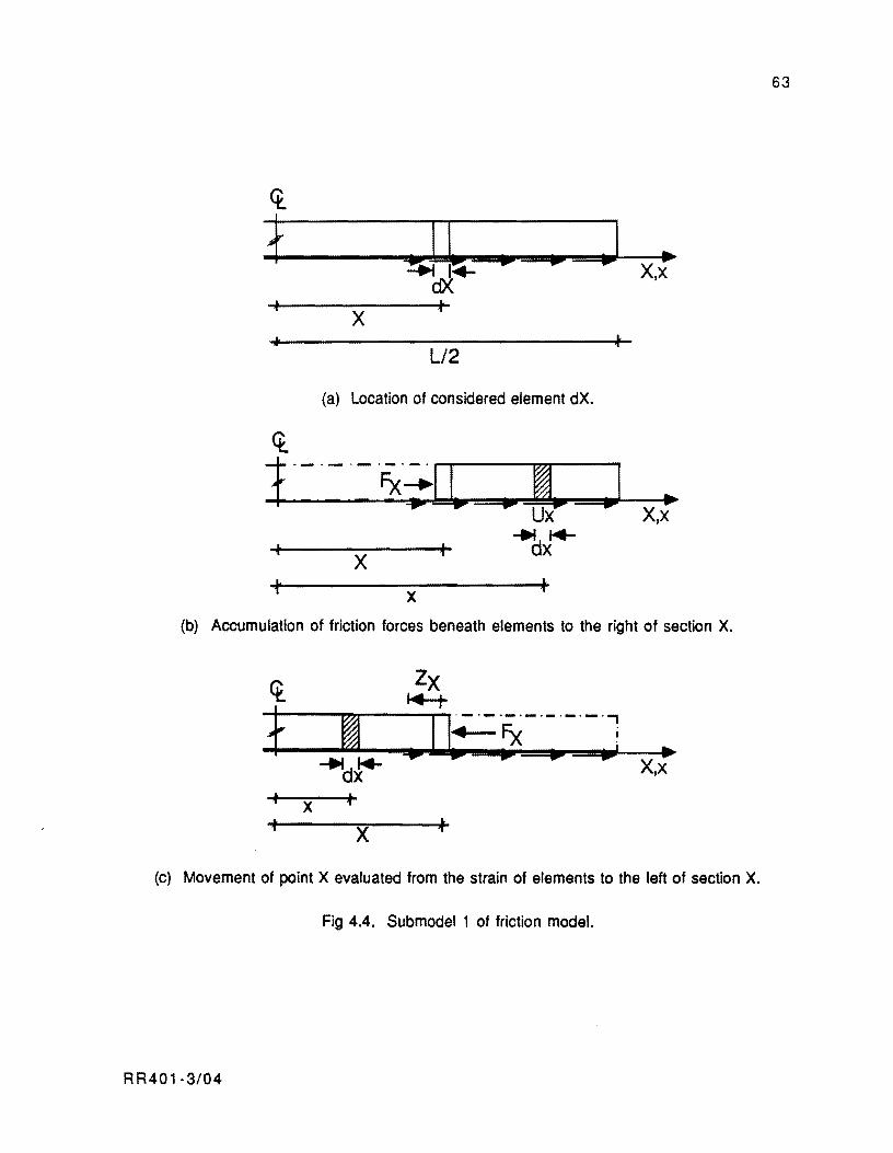
63
<t
+ II .. .. .1 ... "'e-i I~ X,X
dX +
X ~'
.. '" L/2
(a) Location of considered element dX.
.1 ... X,X
X t x
(b) Accumulation of friction forces beneath elements to the right of section X.
ct Zx I-4-t
t ~ ... 1
.-~-,.-.-.-.-.-.,
+-Fx i '.. .. .. .; ... -"''d~ X,X
• X t t
X ~
(c) Movement of point X evaluated from the strain of elements to the left of section X.
Fig 4.4. Submodel 1 of friction model.
RR401-3/04
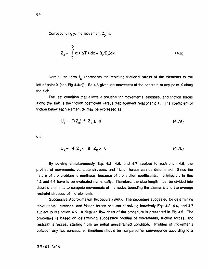
64
Correspondingly, the movement Zx is:
x Zx = J a.. ~T. dx + (f/Ec)dx
o (4.6)
Herein, the term fX represents the resisting frictional stress of the elements to the
left of point X [see Fig 4.4(c)]. Eq 4.6 gives the movement of the concrete at any point X along
the slab.
The last condition that allows a solution for movements, stresses, and friction forces
along the slab is the friction coefficient versus displacement relationship F. The coefficient of
friction below each element dx may be expressed as
(4.7a)
or,
(4.7b)
By solving simultaneously Eqs 4.2, 4.6, and 4.7 subject to restriction 4.5. the
profiles of movements, concrete stresses. and friction forces can be determined. Since the
nature of the problem is nonlinear, because of the friction coefficients, the integrals in Eqs
4.2 and 4.6 have to be evaluated numerically. Therefore, the slab length must be divided into
discrete elements to compute movements of the nodes bounding the elements and the average
restraint stresses of the elements.
Successive APllroxjmatjon procedure (SAP>' The procedure suggested for determining
movements. stresses, and friction forces consists of solving iteratively Eqs 4.2, 4.6, and 4.7
subject to restriction 4.5. A detailed flow chart of the procedure is presented in Fig 4.5. The
procedure is based on determining successive profiles of movements, friction forces. and
restraint stresses. starting from an initial unrestrained condition. Profiles of movements
between any two consecutive iterations should be compared for convergence according to a
R R40 1-3/04
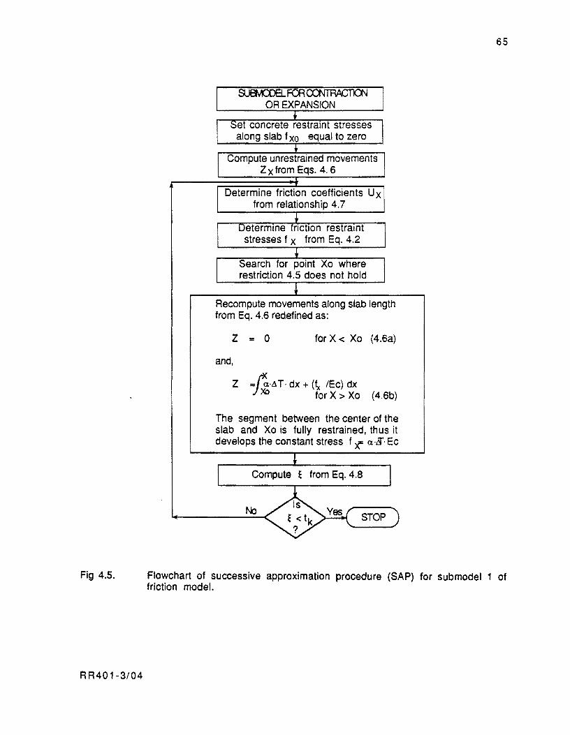
Fig 4.5.
RR401-3/04
65
r SUEfvCOELFai~
OR EXPANSION i-
f -Set concrete restraint stresses
I along slab f xo equal to zero t
f Compute unrestrained movements I
Z x from Eqs. 4. 6
I Determine friction coefficients U x from relationship 4.7
.. I
Determme friction restraint
I stresses f x from Eq. 4.2 ..
r Search for point Xo where
I restriction 4.5 does not hold
~ Recompute movements along slab length from Eq. 4.6 redefined as:
Z ". 0 for X < Xo (4.6a)
and,
Z -IJ:'AT. dx + (fx IEc) dx Xc for X> Xo (4.6b)
The segment between the center of the slab and Xo is fully restrained, thus it develops the constant stress f';(' (X·Li· Ec
~
r Compute E from Eq. 4.8 I No ~ ~ < tk es \. STOP
?
Flowchart of successive approximation procedure (SAP) for sub model 1 of friction model.
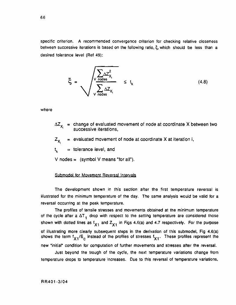
66
specific criterion. A recommended convergence criterion for checking relative closeness
between successive iterations is based on the following ratio, ~,which should be less than a
desired tolerance level (Ref 49):
where
"'" tJ.Z2 L.J x· v nodes I
(4.8)
= change of evaluated movement of node at coordinate X between two successive iterations,
= evaluated movement of node at coordinate X at iteration i,
= tolerance level, and
V nodes = (symbol V means "for all").
Submodel for Moyement Reversal Intervals
The development shown in this section after the first temperature reversal is
illustrated for the minimum temperature of the day. The same analysis would be valid for a
reversal occurring at the peak temperature.
The profiles of tensile stresses and movements obtained at the minimum temperature of the cycle after a .6. T 1 drop with respect to the setting temperature are considered those
shown with dotted lines as fX1 and ZX1 in Figs 4.6(a} and 4.7 respectively. For the purpose
of illustrating more clearly subsequent steps in the derivation of this submodel, Fig 4.6(a) shows the term fX1/Ec instead of the profiles of stresses fX1 ' These profiles represent the
new "initial" condition for computation of further movements and stresses after the reversal.
Just beyond the trough of the cycle, the next temperature variations change from
temperature drops to temperature increases. Due to this reversal of temperature variations,
R R401-3/04
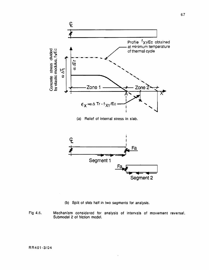
Fig 4.6.
RR401·3/04
Profile f X1/Ec obtained
.. _._._0._,._ ...... /
at minimum temperature of thermal cycle
'- "
b ..... ~ "
t5 " ".
'. ',' '.
-I---Zone 1 Zone 2'~
(a) Relief of internal stress in slab.
<t I I
~1--------------~~Fa
+ -.----.=-' Segment 1
, ......
(b) Split of slab half in two segments for analysis.
67
Mechanism considered for analysis of intervals of movement reversal. Submodel 2 of friction model.
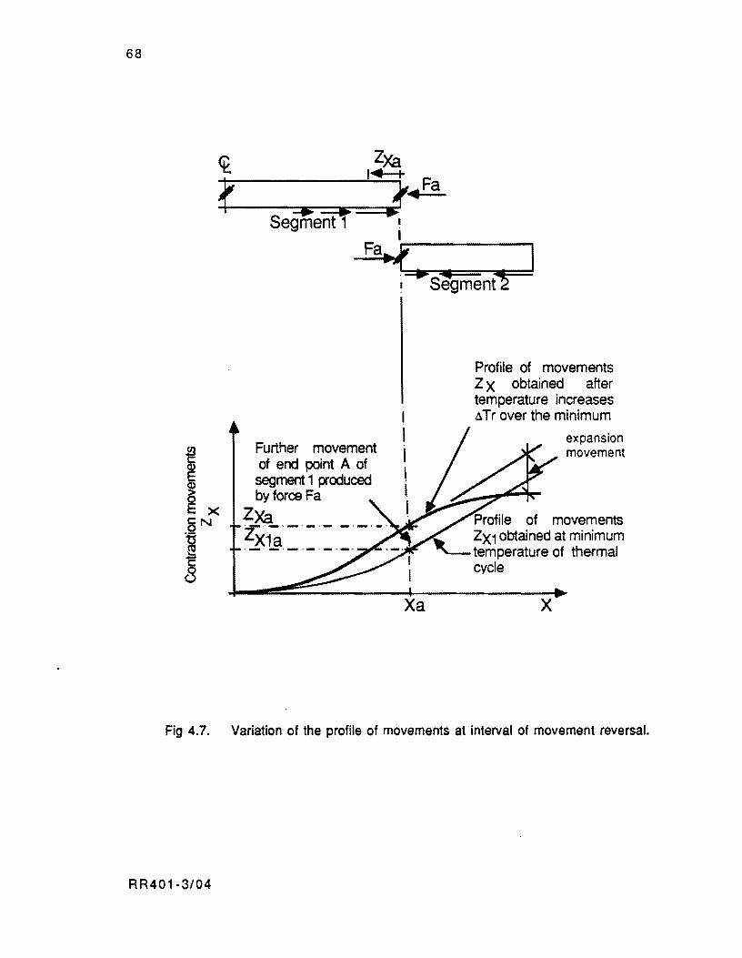
68
Further movement of end point A of segment 1 produced by force Fa
ZXa ZX1~·-·---·-·-,--_._._._._.
Xa
Profile of movements Z X obtained after temperature increases aTr over the minimum
expansion movement
Profile of movements ZX1 obtained at minimum temperature of thermal cycle
x
Fig 4.7. Variation of the profile of movements at interval of movement reversal.
R R401·3/04
69
the elements of the slab are assumed to relieve the restraint stresses first. and then to
experience expansion deformations. The elements that first experience the movement
reversal are those at the slab ends with lower restraint stresses accumulated from the
contraction stage. This situation is illustrated in Fig 4.6(a). Following a temperature increase equal to .1 T r with respect to the minimum, the elements to the left of point A [Zone 1
in Fig 4.6(a)] relieve part of the tensile stress fX1 accumulated up to the trough. The part of
restraint strain relieved by these elements is equal to ex. .1 T r [see Fig 4.6(a)]. The
elements to the right of point A (Zone 2) relieve totally the restraint stress fX 1 and then tend
to develop the expansion unit deformation EX • (ex • .1 T r • fX 1/EC) [dashed line in Fig
4.6(a)]. Following the friction force versus movements curve in Fig 3.13 in Chapter 3, the
elements to the right of point A (Zone 2) start developing friction forces in the opposite
direction as soon as they reverse movement.
For the purpose of modeling this transition stage, the half slab should be analyzed by
dividing it in two segments. Segment 1 in Fig 4.6(b) is to be analyzed subject to the net temperature change (.1 T 1 +.1 T r) from the setting temperature plus the internal force Fa
acting at the end of the segment. .1 T 1 representing a temperature drop is negative in this
derivation. The force Fa is the internal reaction that segment 2 communicates to segment 1
when it tends to expand. This reaction force allows the equilibrium of segment 2. If the effect of the internal force Fa on segment 1 is neglected, the elements of segment 1 should relieve the
tensile stress without experiencing further movements with respect to the "initial" position ZX1' This situation arises as a result of neglecting the elastic recovery in the typical friction
force versus displacement curve. However, the internal force Fa shifts the movement profile
of segment 1 from ZX1 to Zx. as illustrated in Fig 4.7.
Segment 2 should be analyzed considering that its elements tend to develop the
expansion unit deformation:
(4.9)
The analysis of both segments should follow the principles of submodel 1 based on Eqs
4.1 through 4.7. However. some of the expressions should be modified slightly. For segment
RR401·3/04

70
1, the stress equation Eq 4.2 should include the internal force Fa acting at the end of the
segment:
x
fx = F i D + J Ux • 'Y • dx o
Equation 4.6 should be restated as:
x
Zx = J a. • (~T1 + ~Tr) dx + (fx'Ee) dx o
(4.10)
(4.11 )
For segment 2. the movement of the end point A of segment 1 due to the internal force F a [term (Zxa - ZX1 a) in Eq 4.13 below] plus the expansion movements experienced by
segment 2 (integral in Eq 4.13) should be added to the initial contraction movement Zx 1 to
obtain the net movement Zx with respect to the zero movement condition at the setting time
(reference time). Therefore. Eq 4.6 should be redefined as
where
and,
R R401·3/04
X
Zxr = (Zxa - ZX1) + J ex dx + (flEe) dx Xa
(4.12)
(4.13)
expansion strain of the elements between point A and the point X
considered within segment 2 (defined by Eq 4.9).
71
fx = concrete stress of the points between point A and point X,
Zxa = movement of end point A of segment 1 evaluated from Eq 4.11
(see Fjg 4.7),
ZX1a = "initial" contraction movement of end point A of segment 1 (see Fig
4.7), and
ZXr = expansion reversal experienced by the points of segment 2 starting
from the initial contraction ZX1 (see Fig 4.7).
The term fx in Eq 4.13 should be evaluated from the following expression:
l/2
fx = f Uxr • '1 • dx x
(4.14)
where the friction coefficients Uxr should be determined from relationship 4.7 as a function
of the reversal Zxr:
(4.1Sa)
or,
(4.1Sb)
Iteratlye Solution. Due to the nature of the development presented above, a numerical
iterative technique ideal to solve for movements, stresses and friction forces along the slab. First, for the specific amount of temperature reversal ~ T r' the coordinate Xa which defines
the length of each segment should be defined. The iterative procedure starts at this point and
consists of applying the successive iterative procedure (SAP) proposed for submodel 1
consecutively on both segments. When applying SAP to the solution of each segment, the
mathematical expressions corresponding to each segment should be substituted as indicated
above. In order to facilitates the reader's understanding of the procedure, a flow chart of the
solution scheme is presented in Fig 4.8. By applying SAP on segment 2, an estimate of the
R R401-3/04
72
reaction force Fa should be obtained, which if input immediately Into the SAP procedure for
segment 1 allows an estimate of the movement ZXa of point A to be determined. A consecutive
sequence of applications of SAP to segments 2 and 1 completes one iteration. The last estimate of ZXa in any iteration permits to recompute Fa by applying SAP on segment 1 again. In each
iteration, the profiles of movement Zx of the slab half (which is the profile of movements of
both segments put together) should tend to converge. The same convergence criterion as for
the first submodel is applicable to this submodel. Profiles of movements, friction
coefficients, and stresses along the slab are obtained after convergence is reached.
Incremental Approach and First Temperature Cycle
It is obvious that the solution for a complete temperature daily cycle can be achieved
by combining the solutions presented earlier for the part of contraction and expansion and for
the intervals of movement reversal.
Following a time incremental approach, the application of submodel 1 permits solution
for the first temperature variations, at specific time increments (2-hour increments in
Computer Program PSCP1 to be described later), starting at the setting hour if the predicted cycle is the first cycle. The volumetric strains Ex to be input in the procedure should be
determined with respect to the setting temperature for the first time increment and, then,
increased or decreased (depending on the nature of the temperature change) with respect to
the temperature of the last time increment considered.
After the first temperature reversal, part 2 of the model is applicable. The initial
conditions for stresses and movements in this case are those obtained by the time of the
reversal. This part of the model continues to apply for the next time increments until the
movement reversal interval is completed and the stresses in the slab become of one nature
again, either tensile or compressive. Then, the first submodel is applicable again. However, the term EX = (ex .• .1T r - fX1 /Ec)' which is variable for each element, should replace the
constant term a • T in Eqs 4.3 to 4.6 of the first submodel.
Fig 4.9(a) illustrates the shape of the profiles obtained for a daily temperature cycle
every four hours, in a 240-ft. slab, for a setting hour around 8 AM, near the minimum
temperature of the cycle. These profiles were obtained from computer program PSCP1,
whose main features will be addressed in Chapter 6, for a daily temperature variation of 35°F
R R401-3/04
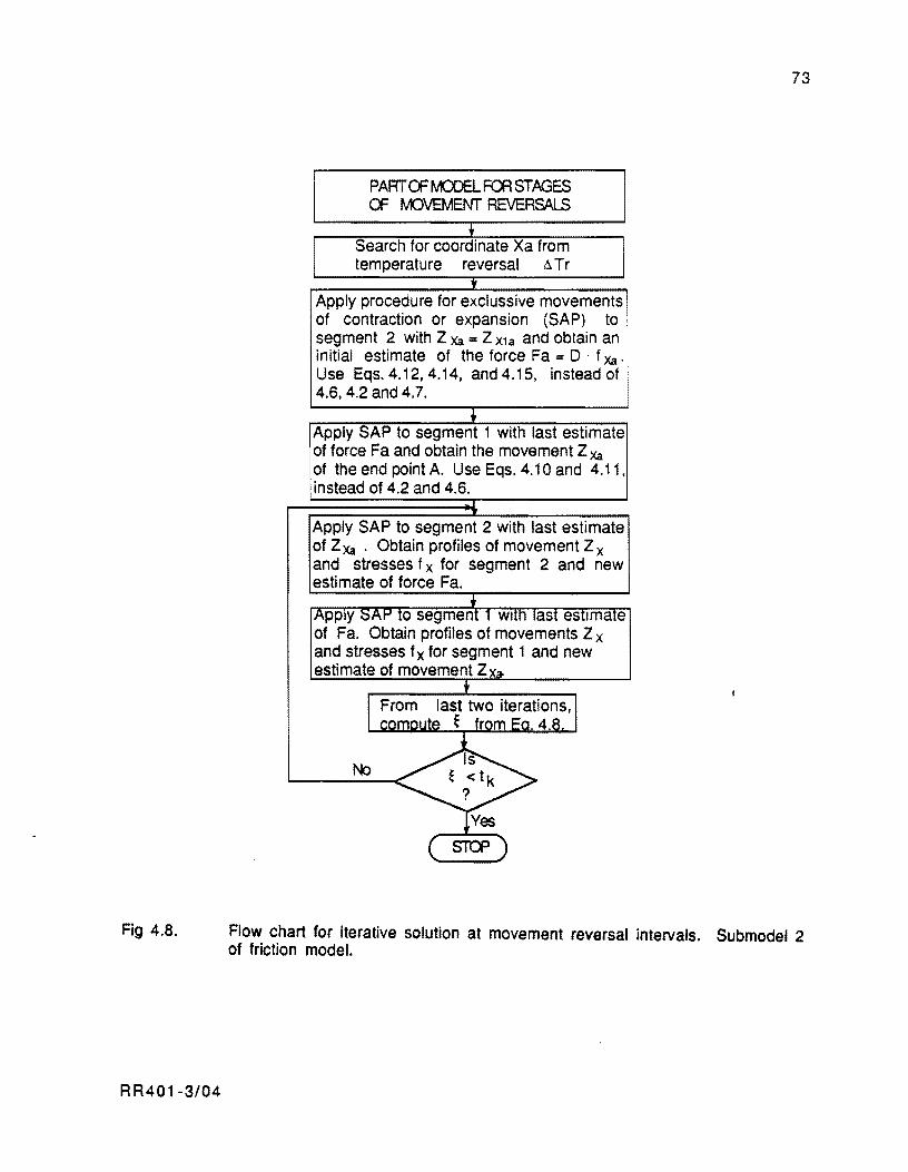
Fig 4.8.
RR401-3/04
PART OF MCOEL ~ STAGES OF MJVEMENT REVERSALS
Search for coordinate Xa from temperature reversal .:l Tr
Apply procedure for exclussive movements of contraction or expansion (SAP) to segment 2 with Z Xa = Z X1a and obtain an initial estimate of the force Fa = D . f Xa. Use Eqs. 4.12, 4.14, and 4.15, instead of 4.6,4.2 and 4.7.
Apply SAP to segment 1 with last estimate of force Fa and obtain the movement Z Xa
of the end point A. Use Eqs. 4.10 and 4.11, instead of 4.2 and 4.6.
Apply SAP to segment 2 with last estimate of Z Xa • Obtain profiles of movement Z x and stresses f x for segment 2 and new estimate of force Fa.
73
Flow chart for iterative solution at movement reversal intervals. Submodel 2 of friction model.
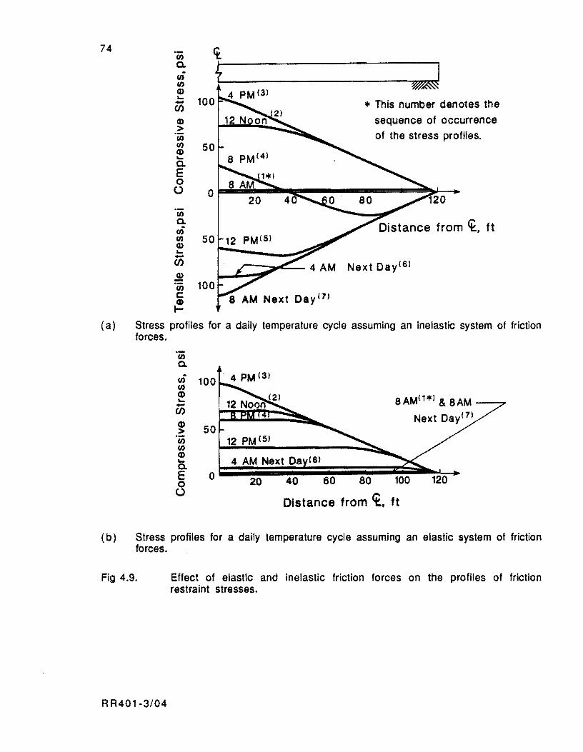
74 .- ct en Co
+ ;J . en en Q) ....
100 - * This number denotes the CI:J Q) sequence of occurrence > en of the stress profiles. en 50 Q) .... Co E 0
(..) 0 20
en Co en en 50 12 PM(S) Q) .... -CI:J Next DaylS) ~ 100 en c Day (7)
~ (a) Stress profiles for a daily temperature cycle assuming an inelastic system Of friction
forces . . -en Co
",; 100 4 PM (3)
en Q)
8AM(1*' & 8AM .... -CI:J Q)
50 > en 12 PM (5) en Q)
4 AM Next Da (6) .... Co E 0 20 40 60 80 100 120 0
(..)
Distance from ct., ft
( b) Stress profiles for a daily temperature cycle assuming an elastic system of friction forces.
Fig 4.9.
R R401-3/04
Effect of elastic and inelastic friction forces on the profiles of friction restraint stresses.
75
and the friction coefficient versus displacement curve presented in Fig 3.4 for a single
polyethylene sheeting layer.
Figure 4.9(b) illustrates the sequence of profiles that are obtained if the friction
forces beneath the slab are conSidered elastic. These profiles were obtained from computer
program JRCP3 (Ref 36). In this case, since the setting temperature is around the minimum
temperature of the day and the friction forces are assumed as elastic, the pavement develops
only compressive stresses during the entire cycle.
Simulation of Consecutive Cycles
The simulation of consecutive cycles can be achieved following the principles described
earlier as applicable after the first temperature reversal of the first temperature cycle. The position reached by the slab elements at a specific reversal ZXi and the restrained strain of
the elements fXi/Ec represents the initial condition for computation of further movements and
stresses after the reversal. After reversal i, the slab has to go through a relieving process of
the restrained strains first that can be modeled with submodel 2. Once this stage is completed,
submodel 1 is applicable until the next reversal occurs. Then, submodel 2 can be applied
again for the subsequent cycle.
As indicated in earlier sections of this chapter, the unit deformations ex which the slab
elements tend to experience after a reversal should be determined with respect to the initial
condition defined at the reversal. The unit deformations eXi of the elements after reversal
should. then, be determined as follows:
where
...
~T. "" n
RR401-3/04
(4.16)
unit deformation an element dx located a distance X from midslab tends
to develop after the reversal i,
magnitude of temperature change with respect to peak or through
temperature at reversal i, restrained strain of element dX reached at reversal i.
76
The unit deformations EXi from Eq 4.16 are the unit deformations that should be input
into submodels 2 and 1 consecutively for analyzing the cycle after reversal i. The position
reached by the slab elements at the end of this cycle and the restrained strains of the elements
represent the initial condition for computation of movements and stresses at the subsequent
cycle, after reversal i+ 1.
Figure 4.10 and 4.11 show consecutive cycles of movement and stress determined
from computer program PSCP1. PSCP1 works based on the principles described earlier.
Both figures were developed for 440·ft. slabs placed on a single layer of polyethylene
sheeting, for a 35°F daily temperature variation.
Figure 4.10 depicts the trend of movement of end and quarter points of the slab. The
increase in amplitude of the cycles is a result of the increase of the concrete elastic modulus
with time. PSCP1 takes into account this effect. From Eq 4.16, it is obvious that such an
effect may be expected inasmuch as increments of elastic modulus result in increments of the unit deformation EX of the elements. Appendix A describes the procedure adopted from the
literature (Aef 35) for evaluating concrete elastic modulus as a function of time.
In Fig 4.11, the effect of the increase of elastic modulus with time is apparent in the
first cycle of stresses. It can also be observed that a steady state condition is reached in
subsequent cycles. In Fig 4.11, the effect of the setting hour on the concrete stresses
developing during the first hours is evident too. Since the slab is set at 10 AM (early morning
casting), compressive stresses develop during the first hours. However, tensile stresses
start building up after the reversal of the afternoon peak (4 PM).
LENGTH CI-W'JGES DUE TO SEASONAL CYCLES AND OTHER LONG TERM EFFECTS
Length changes due to seasonal cycles, whether caused by the slow normal changes in
moisture content, creep, or other sources of long term movement occur over many days with
relative minute daily movements. To integrate the effect of these factors into the analytical
procedure described earlier requires not only the addition of the corresponding strains taking
place during the each specific time increment to the strains produced by the temperature variations (a • 6T or a • 6T
r). The magnitude of these strains is so small in comparison
with the daily contraction and expansion strains due to temperature that the cumulative length
A A401·3/04
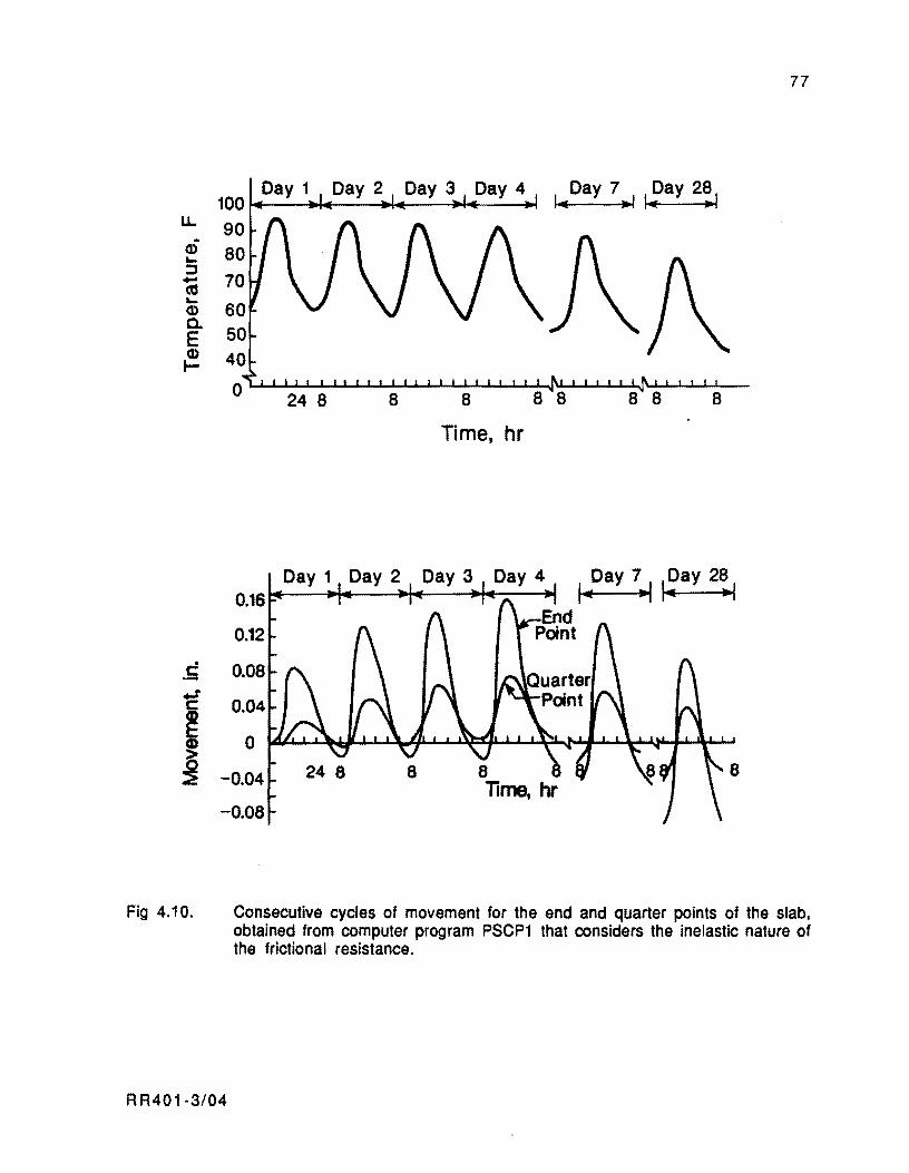
LL.. ~
(J) ... ::::J -as ... (J) c. E (J) ....
.S
Fig 4.10.
77
100~--~.---~.---~~--~
90
24 8 8 8 8 8
Time, hr
Consecutive cycles of movement for the end and quarter points of the slab, obtained from computer program PSCP1 that considers the inelastic nature of the frictional resistance.
RR401·3/04
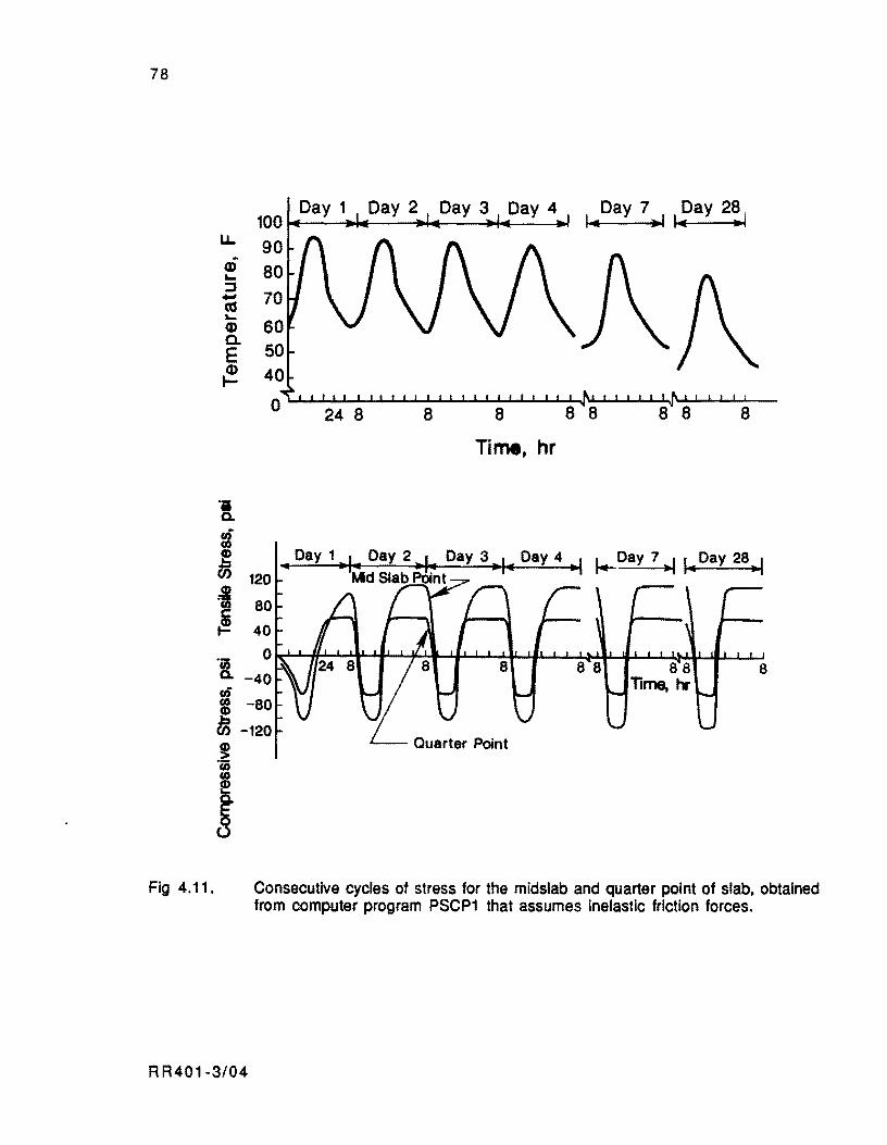
78
Fig 4.11.
u. Q) .... ::J ... as .... Q) a. E Q) I-
!. :-~ =! ~
'8, -40 tIi ~ -80
DJ -120
I
24 8 8 8
Time, hr
Day 7 Day 281 I.. .! I... ..
8
.. Day 1 .. , It Day 2 .. 1• Day 3 .. 1 .. Day 4 ---I J+..-Day 7 .,11 .. Day 28 .. 1 Md Slab Point
8
Consecutive cycles of stress for the midslab and quarter point of slab. obtained from computer program PSCP1 that assumes inelastic friction forces.
RR401-3/04
79
changes occur without frictional resistance in this procedure that incorporates the
inelasticity of the friction forces. This may be evidenced from Figs 4.10 and 4.11. The shift
of the movement cycles in Fig 4.10 for the 7th and 28th days toward the negative zone of the
graph, which respresents contraction movements, is a result of accumulated shrinkage.
However, the friction stress cycles in Fig 4.11 develop from the daily temperature changes
with disregard to cumulative shrinkage and, for the most part, are practically the same from
one day to another. The model used inside PSCP1 for evaluating shrinkage strains as a
function of time is the one proposed by Hansen and Mattock in Ref 39. The mathematical
expression is given in Appendix A. The model for creep is discussed in Chapter 5, which deals
with the prestress forces related effects.
Solution for Rejnforced and Cracked pavements
Although the solution for friction stresses and restrained movements was derived for
plain concrete slabs, it can also be used for uncracked pavements with conventional
reinforcement. Before the slabs develop any cracking, the effect of conventional bonded
reinforcement on the movements and stresses of the slab is almost negligible.
For cracked pavements, the solution for stresses is not valid because, when the
pavement cracks, there is a redistribution of the friction related stresses from the concrete to
the steel at the cracks. Away from the cracks, the friction stresses are restored to the
concrete again through bonding forces between the concrete and the steel. However, the
solution for movements is still valid if a reduced elastic modulus is introduced in the analysis
to account for the effect of the transverse cracking on the pavement.
SUMMARY
The problem to be solved in this research to model the behavior of PCP slabs has been
defined in this chapter. The numerical solution involves the important factors and is in a
form that provides complete information, in terms of displacements and stresses, useful in
the design of PCP slabs. The slab should be analyzed in, at least, three time periods:
RR401-3/04

80
( 1 ) From the analysis of an initial period. the mechanism of movements and
stresses during the pavement first hours can be studied. including the effect of
application of prestress forces. The information generated for this period is
essential for assessing time of casting and time and amount of prestress to
apply at given stages to minimize problems with premature cracking of the
slabs.
( 2 ) From the second period, representing a summer day at the end of the pavement
design life, the critical stress combination of friction and curling stresses can
be determined. This information is necessary in the design of thickness and
prestress level of the slabs.
(3) From a final period, representing a winter day at the end of the pavement
design life, the. maximum joint opening can be evaluated. This term is
essential for designing the length of the PCP slabs.
The derivation of a model for longitudinal movements restrained by the friction,
considering the inelastic nature of these forces, is also presented in this chapter.
This model is composed of two submode[s:
( 1 ) The first submodel, to simulate the contraction or expansion of the slabs away
from maximum or minimum temperatures of the thermal cycle.
(2) The second submodel, to simulate the stress relief mechanism and reversal of
movements of the slabs. immediately after maximum or minimum
temperatures of the thermal cycle.
The friction model derived in this chapter is innovative and. at the same time. more
realistic than previously developed friction models.
RR401·3/04
slabs:
CHAPTER 5. MODEUNG THE EFFECT OF PRESTRESS FORCES
In the preceding chapter. three periods of analysis were outlined for the design of PCP
( 1 ) An initial period for studying the stresses in the pavement during the first
hours after the setting hour.
(2) A second period for obtaining the critical stress combination, required to
design the thickness and prestress level of the slabs.
(3) A final period for designing maximum jOint opening and minimum level of
prestress.
For the first prediction period, the stress cycles developing from consecutive
temperature cycles start replicating a short time after the setting hour. This fact was typified
in Chapter 4 with predictions from Computer Program PSCP1. The time required for the
concrete to gain substantial strength is also the time required for the stresses to reach the
stability condition. This stability condition is broken when prestress forces are applied. The
unsteady condition thus obtained is of a transient nature for the steady state is shortly
reestablished inasmuch as slab movements continue to occur as a result of daily temperature
changes regardless of the prestress force. To determine the time dependence of movements and
stresses during this transient stage is the problem considered in the first part of this chapter.
For periods of prediction subsequent to the initial period. the assumption will be made
that the analysis interval takes place sometime after the completion of prestressing. Since the
frictional forces occur independently of the prestress. it is valid to superimpose the prestress
level on the profiles of friction restraint stresses developed during the study interval.
Therefore. the subject in the second part of this chapter is to quantify the losses occurring up
to the beginning of the analysis period considered. and then define the remaining prestress
level to superimpose throughout the period. Additional discussion will also be provided
regarding computation of friction stresses and restrained movements for these periods.
RR401-3/05 81
82
MODEUNG THE PRESTRESS APPLICATION EFFECT AT THE INITIAL PREDICTION PERIOD
Modeling the behavior of long PCP slabs assuming inelastic friction forces has to be
handled with a time incremental approach. The effect of prestress forces can be included in
this approach by applying the principle of superposition. Figure 5.1 (a) and (b) illustrate
that if segment A8 is in equilibrium, the concrete stresses should be equal to the
superposition of stresses due to the two external forces: friction and prestress. Whether the
stresses generated by the friction decrease or increase the precompression depends on the
direction in which the friction forces develop as a result of the slab movements. This aspect is
demonstrated in Fig 5.1 (a) and (b). In this context, the friction forces may arise as a result
of two movement types:
(1 ) Temperature induced movement.
( 2 ) The contraction movement produced at prestress force applications.
The effect of post-tensioning on PCP slabs can be modeled if. in the progression of
movements and stresses due to temperature changes, the contraction produced by the prestress
can be included. This contraction affects the friction forces which will react by opposing the
prestress contraction movement. The final stresses in the pavement can be readily determined
by superimposing the stress caused by the friction forces thus obtained on the precompression
due to the prestress. To induce in the slab elements a contraction strain EX == Afc/Ec creates a slab
contraction and corresponding friction forces (Ref 50). The term Afc/Ec is composed of the
concrete stress Afc due to the prestress in the numerator and the concrete elastic modulus Ec
at the time of prestressing in the denominator. The contraction strain should be introduced at the time increment when the prestress force inducing the concrete stress change afc is
applied. As an example. consider the sequence of temperature shown in Fig 5.2, for the first
120 hours after setting of a 440-foot slab placed on a single polyethylene film. A
concrete coefficient of contraction and expansion of 5x10⁻⁶ inch/inch-oF is assumed in
this example. The slab is cured at 12 AM and post-tensioned 36 hours later. A total prestress
of 215 ksi is applied to 0.6-inch seven-wire strands (0.26 inch2) spaced 24 inches center to center. This force results in a concrete stress Afc of 322 pSi. for a 6-inch-thick PCP slab.
Assuming that the concrete elastic modulus Ec after 36 hours is 2,400,000 psi. the
RR401-3/05

83
-+i 1+ J
n ax L
x
L/2 FX= f xUx·'Y·O·dx + Fs
(a) The friction forces reduce the concrete precompression when the slab contracts.
n
l·-·-·-x-~~·-~~ 4
n x
L/2 FX= I XUX''Y·O·dX + Fs
(b) The friction forces increase the concrete precompression when the slab expands.
Fig 5.1. Superposition of stresses produced by friction and prestress.
RR401-3/05
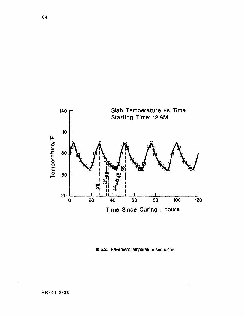
84
140
110 u. o
0; "-
.a 80 «J "-(I) a. E ~ 50
Slab Temperature vs Time Starting Time: 12 AM
20 ~----~~~~~~~----~----~------o 20 60 80 100 120
Time Since Curing, hours
Fig 5.2. Pavement temperature sequence.
R R401·3/05
85
contraction strain EX to be induced in the slab after 36 hours is equal to flfC/EC = 0.0001323
inch/inch. The effect of the sudden contraction can be noticed on the diagram of slab and
movement versus time in Fig 5.3 by a downward shift in the trend of movements. This graph
was obtained with computer program PSCP1.
The time required for the movement to stabilize after the contraction is nearly 12
hours following post-tensioning, as shown in Fig 5.3. After 12 hours, the movements become
the "mirror-image" of the corresponding movement in a graph in which the contraction effect
is not included. Given that the magnitude of the slab movements is dependent on the concrete
volumetric strains, the slab length. and the base restraining characteristics, this stabilizing
time would be greater for longer slabs cast on bases offering a higher resistance to the slab's
longitudinal movements. For slabs on friction reducing membranes, the stability condition is
reestablished in the next temperature cycle after the prestress force is applied.
Stress profile Diagrams
The approach adopted herein for simulating the effect of prestress application can be
explained by analyzing the sequence of stress profiles along the slab between Hours 28 and 52.
Fig 5.2 shows that a peak temperature is reached 28 hours after the setting hour. The stress
profile obtained from the setting time up to this hour using a simulation with Computer
Program PSCP1 is shown in Fig 5.4. Subsequent temperature drops after the peak values
causes slabs contraction and the profiles to shift upwards, toward the tensile stress zone as
shown for Hours 30, 32, and 34 in Fig 5.4. Since the entire slab is in tension by Hour 34.
the friction force vectors beneath the slab should oppose the movement. i.e., that from the
slab center toward the slab ends.
The contraction produced by the prestress at Hour 36 develops the maximum friction
coefficients beneath the slab (0.96 for single film polyethylene according to Fig 3.4).
Therefore, the maximum attainable friction forces are obtained beneath each point of the slab.
Since this represents a constant force per unit length, it follows immediatelly that the
stress profile due to friction must be a straight line, as shown in Fig 5.4 for Hour 36. The slope of this line is defined by the maximum friction coeffiCient, Umax' and the concrete unit
weight, y. according to the following relationship:
R R401-3/05
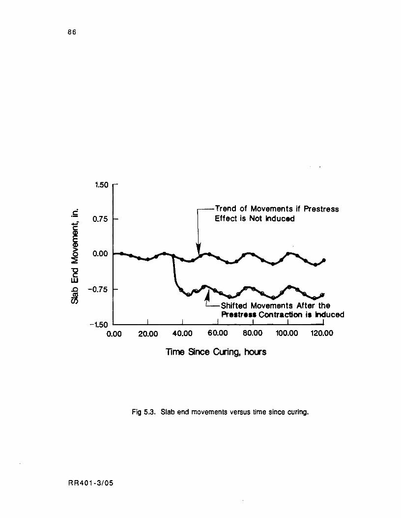
86
.~
1.50
0.75 Trend of Movements if Prestress Effect is Not Induced
! 0.00 r ............ J..".,.,.- __ ~ __
'E w .0 -0.75
~ LShifted Movements After the Pr •• tr ••• Contraction i. Induced -1.50 L-__ ~ ________ "'-__ '-"" __ """"' __ _
0.00 20.00 40.00 60.00 80.00 100.00 120.00
lime Since elling. hol.I's
Fig 5.3. Slab end movements versus time since curing.
RR401-3/05
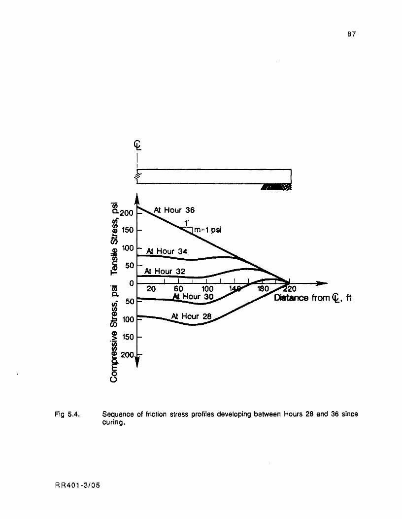
Fig 5.4.
RR401·3/05
~ I
'CiS a.
I
o 50~----~~~~ UJ
i .~ 150 ~ ~200
8
87
L
Sequence of friction stress profiles developing between Hours 28 and 36 since curing.
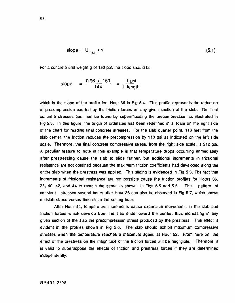
88
slope = Umax • Y
For a concrete unit weight g ot 150 pct, the slope should be
slope 0.96 x 150
= 144 = 1 psi
ft length
(5.1 )
which is the slope of the profile for Hour 36 in Fig 5.4. This profile represents the reduction
of precompression exerted by the friction forces on any given section of the slab. The final
concrete stresses can then be found by superimposing the precompression as illustrated in
Fig 5.5. In this figure, the origin of ordinates has been redefined in a scale on the right side
of the chart for reading final concrete stresses. For the slab quarter point, 110 feet from the
slab center, the friction reduces the precompression by 110 psi as indicated on the left side
scale. Therefore, the final concrete compressive stress, from the right side scale, is 212 psi.
A peculiar feature to note in this example is that temperature drops occurring immediately
after prestressing cause the slab to slide farther, but additional increments in frictional
resistance are not obtained because the maximum friction coefficients had developed along the
entire slab when the prestress was applied. This sliding is evidenced in Fig 5.3. The fact that
increments of frictional resistance are not possible cause the friction profiles for Hours 36,
38, 40, 42, and 44 to remain the same as shown in Figs 5.5 and 5.6. This pattern of
constant stresses several hours after Hour 36 can also be observed in Fig 5.7, which shows
midslab stress versus time since the setting hour.
After Hour 44, temperature increments cause expansion movements in the slab and
friction forces which develop from the slab ends toward the center, thus increasing in any
given section of the slab the precompression stress produced by the prestress. This effect is
evident in the profiles shown in Fig 5.6. The slab should exhibit maximum compressive
stresses when the temperature reaches a maximum again, at Hour 52. From here on, the
effect of the prestress on the magnitude of the friction forces will be negligible. Therefore, it
is valid to superimpose the effects of friction and prestress forces if they are determined
independently.
RR401-3/05
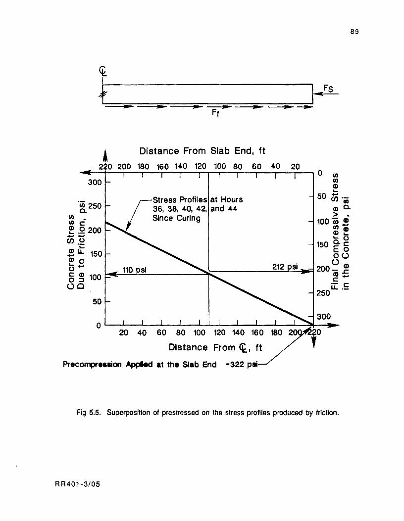
<k I
, Distance From Slab End, ft
220 200 180 160 140 120 100 80 60 40 20 ~~~--~~--~--~--~~--~--~--~~--~O 0
300 o Q) ....
Stress Profiles at Hours 50 en 'iii .~ 250 36, 38, 40, 42, and 44 Q) 0.
~ C Since Curing 100 ,~ i ~ ,2200 = ! -- .... 0 (J) .g 150 ~ 5 ! u.. 150 0 U Q)o UQ) 0- ~~~~~~' ________ ~~~ _________ 2_1_2~~_'~200~~ 5 ~ 100 c: -UC ~E
50
120 140 160
Distance From <k., ft
Precompreuion AppIed at the Stab End -322 psi
250
300
Fig 5.5. Superposition of prestressed on the stress profiles produced by friction.
RR401-3/05
89
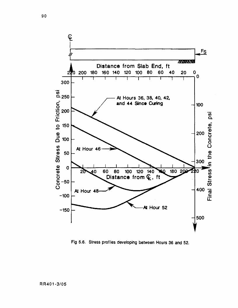
90
~ I I
+ _J--FS Distance from Slab End, ft
180 160 140 120 100 80 60 40 0 --~--~~--~--~--~--~~--~--~--r-~O 300
en 0.250 .. c: o += 200 (J
u: o 150 -
At Hours 36, 38, 40, 42, and 44 Since Cl.I'ing
-150 L=-................ _ ...... ---
Fig 5.6. Stress profiles developing between Hours 36 and 52.
100
en a. oj -Q)
200 "(J c: o U Q)
..c: -
R R401-3/05
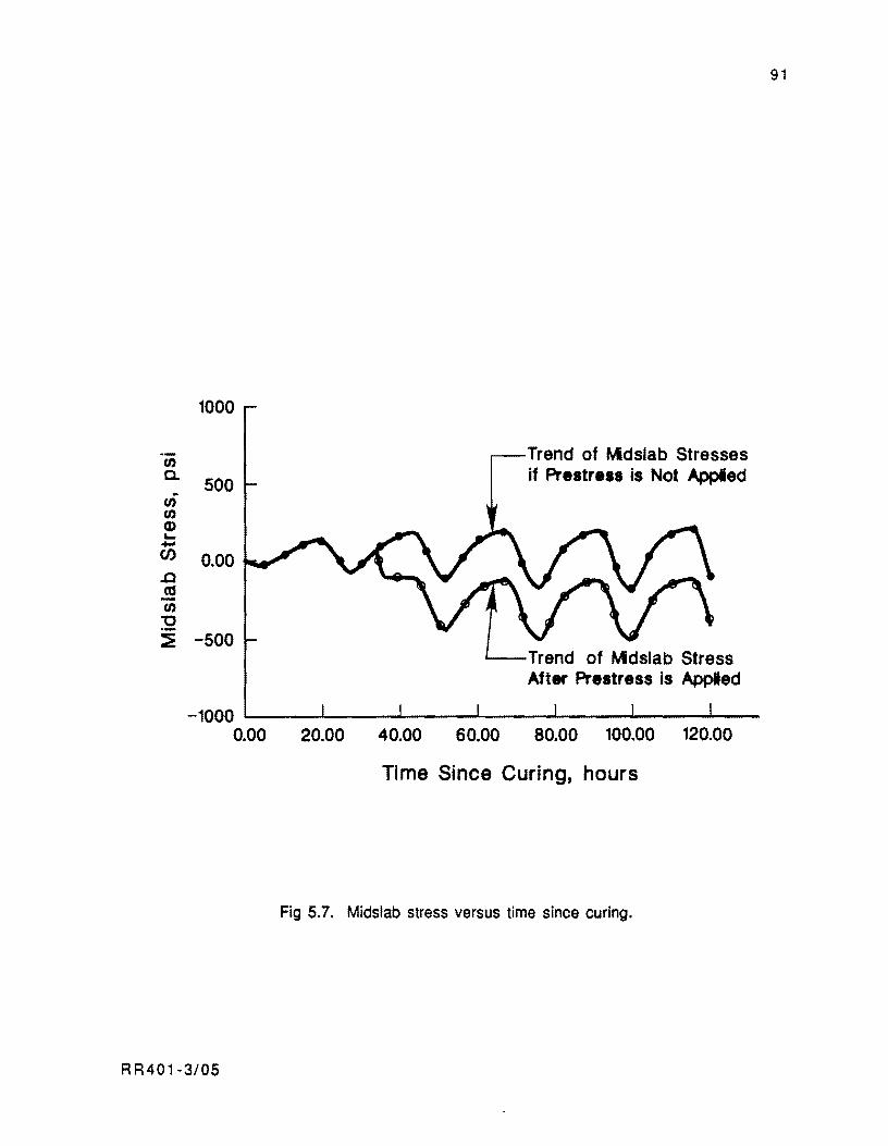
-U) U) Q) .... -(/)
..0
.! U)
32
1000
500
0.00
:E -500
Trend of Mdslab Stresses if Prestress is Not AppIed
'---Trend of Mdslab Stress After Prestress is Applied
-1000 ~----~----~----~----~----~----~~--0.00 20.00 40.00 60.00 80.00 100.00 120.00
Time Since Curing, hours
Fig S.7. Midslab stress versus time since curing.
R R401-3/0S
91

92
The effect of the prestress is to shift the friction profiles an equal amount to the
precompression being applied at the slab ends. The final stresses in the concrete will be the
"mirror-image" of the friction profiles. Likewise, the friction forces will develop primarily
as a result of the daily temperature related movements, thus practically unrestrained by the prestressing steel. This is true because the axial stiffness of the concrete plate (Ec • AdL) is
normally many time greater than the axia.! stiffness of the strands (Es • AJL).
Behavior Assuming Elastic Frjction Forces
If the friction forces were modeled elastically, the prestress force would produce a
thrusting slab movement toward the center with respect to its initial position at the reference
time (setting hour). Hence, most of the slab would work in the sliding range with maximum
friction forces opposing the contraction movement. The daily slab expansion would not suffice
to remove the slab from the sliding zone since the prestress contraction is fairly substantial,
as may be evidenced in Fig 5.3 for the slab end point. During the daily cycle, most of the slab
points would oscillate within the sliding zone, similarly to the response shown for point A (between positions ZAn and Z An-1) in Fig 3.11 in Chapter 3. Since movements within this
zone do not result in changes of the frictional force, the stress profile for Hour 36 in Fig 5.6
would be constantly and indefinitely predicted for all subsequent hours after post-tensioning.
To design a PCP slab considering that the maximum friction forces along the entire slab always
oppose the effect of the prestress is very unrealistic and may lead to very conservative
designs.
Key Assumption
A major assumption in this derivation and inside the Computer Program PSCP1 is that
the prestress applied at the slab ends remains constant during the periods of prediction. This
assumption is valid Since short-term maximum movements, as may be observed for average
conditions in Fig 5.3, fall in the range of the 0.06 inches per 100 feet of slab length.
Movements in this order of magnitude result in negligible variations of the strand's elongation.
The long term slab end movements, on the other hand, may generate as much as 0.5 inch of
contraction per 100 feet of slab length (Ref 4). The necessity to include this effect on the
RR401-3/05

93
prestress level is then evident. This will be the matter of issue in subsequent sections of this
chapter.
LONG TERM PREDICTION OF PAVEMENT RESPONSES
Unlike the initial prediction period required in the design of PCP slabs, the
intermediate and final periods take place long after the setting time. The following
considerations for predicting behavior during these periods arise therefrom:
(1 ) The compatibility relationship between concrete and steel deformations that
governs the average prestress acting on the slab during the period considered
should be derived. This will permit one to evaluate the prestress level after
losses to the friction stresses arising during the period.
(2) The time incremental scheme adopted in this study requires that, for predicting
slab responses during a time period, a simulation of the development of
movements and stresses due to environmental factors. shrinkage. creep. etc.
should be followed starting from the setting hour. By following this simulation,
the initial condition for movements and stresses at the beginning of the period
considered can be obtained. This initial condition is required to determine
further movements and stresses during the period itself. However, it is not
feasible to run a simulation starting from the setting hour for analysis periods
occurring a long time after setting.
Both aspects will be discussed in subsequent sections consecutively.
Long Term Changes of the prestress Leyel
Time dependent variations of the prestress level are produced by slab longitudinal
movements due to seasonal temperature changes, concrete shrinkage and creep, plus
relaxation of the prestressing steel. Evaluations of seasonal temperature related movements
are not a problem per se because the concrete strains during this period are equal to the
temperature change between seasons multiplied by the concrete thermal coefficient of
RR401·3/05
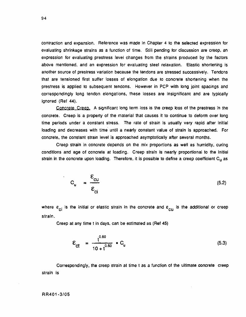
94
contraction and expansion. Reference was made in Chapter 4 to the selected expression for
evaluating shrinkage strains as a function of time. Still pending for discussion are creep. an
expression for evaluating prestress level changes from the strains produced by the factors
above mentioned, and an expression for evaluating steel relaxation. Elastic shortening is
another source of prestress variation because the tendons are stressed successively. Tendons
that are tensioned first suffer losses of elongation due to concrete shortening when the
prestress is applied to subsequent tendons. However in PCP with long joint spacings and
correspondingly long tendon elongations. these losses are insignificant and are typically
ignored (Ref 44).
Concrete Creep. A significant long term loss is the creep loss of the prestress in the
concrete. Creep is a property of the material that causes it to continue to deform over long
time periods under a constant stress. The rate of strain is usually very rapid after initial
loading and decreases with time until a nearly constant value of strain is approached. For
concrete, the constant strain level is approached asymptotically after several months.
Creep strain in concrete depends on the mix proportions as well as humidity. curing
conditions and age of concrete at loading. Creep strain is nearly proportional to the initial
strain in the concrete upon loading. Therefore, it is possible to define a creep coefficient Cu as
= (5.2)
where Eci is the initial or elastic strain in the concrete and Ecu is the additional or creep
strain.
Creep at any time t in days, can be estimated as (Ref 45)
= to.so
.c 10+to.so u
(5.3)
Correspondingly. the creep strain at time t as a function of the ultimate concrete creep
strain is
RR401-3/05
95
= to.GO
--~ .... -10 + to.so (5.4)
Compatibility Relatjonship Between Concrete and Steel Deformations
In this section, the pavement is considered as a material composed of concrete and steel
whose behavior is unaffected by the friction produced by the base material. Relative
movements between concrete and steel are assumed to occur freely. Therefore, the equations
derived herein hold strictly true for the case of unbonded tendons. However, from a practical
standpoint. the solutions are also valid for bonded tendons since the effect of bonding is insignificant before the slabs experience cracking. The initial average stress fci is considered
to be applied in the concrete immediately after prestressing. This is the stress in the
concrete after deduction of the losses due to friction between the tendons and their ducts,
elastic shortening, and anchor set, if any. To satisfy the internal equilibrium of forces between the concrete and steel, an initial tensile stress equal to fsi is considered to be applied
in the steel. If the concrete experiences a unit expansion deformation equal to Ec' the compressive
stress in the concrete will increase under the restraint of the prestress force, with a
corresponding increase of the steel tensile stress. If the concrete were unrestrained by the prestress force. the slab would experience the end movement Ze:
z = e .U2 e c
where L is the slab length. This condition is illustrated in Fig 5.8(a).
(5.5)
In the presence of the restraining force, both materials will experience the same end
movement as shown in Fig S.8(b). Hence, the respective variations of the concrete and steel 6F c and 6F s according to the sign convention adopted in Chapter 4 are
RR401-3/05
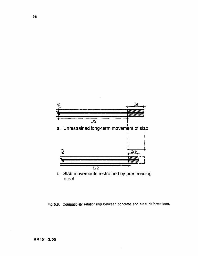
96
+·-----------L'-2----------+t I a. Unrestrained long-term movem~nt of slab
I I . I I . . I I I .. , 4. Zre ..
~-----------------------~~~-, I
t===================~~-~ Ll2
b. Slab movements restrained by prestressing steel
Fig 5.B. Compatibility relationship between concrete and steel deformations.
RR401-3/05
and
liFs =
where
Ec = concrete modulus of elasticity,
Es = steel modulus of elasticity,
Ze = unrestrained end movement,
Zre = actual end movement,
Ac = transverse area of concrete slab,
As = reinforcing steel area.
Equating both terms as follows,
6F =.6F c s
and substituting the end movements by the corresponding strains,
where
RR401·3/05
(e - e )/p = e • n c cr cr
= =
reinforcement percentage,
unrestrained concrete strain,
97
(5.6)
(5.7)
(5.8)
(5.9)

98
= actual concrete strain,
= ratio of steel to concrete elastic moduli.
Solving for the actual strain Ecr'
Ccr = (5.10)
Therefore, the movement ZXr of a point located a distance X from midslab is
C • X c =
1 + pn (5.11 )
Likewise, the changes in concrete and steel stresses, ilfc and ilfs' with respect to the initial
values fci and fsi' respectively, are
(5.12)
and
(5.13)
Substituting Eq 5.10 into relationships 5.12 and 5.13,
= - (5.14) 1 + 1/pn
RR401-3/05
99
and
= (5.15)
For the sake of clarification, the development shown above was presented for the generic concrete strain f
c' In this form, the strains produced by seasonal temperature
variations, shrinkage, and creep occurring from post-tensioning until the time of analysis
should be included.
Steel Relaxation. A significant amount of prestress loss is due to the relaxation
exhibited by the steel strands. Steel relaxation is defined as the loss in steel stress when it is
held at a constant strain level. Equation 5.16 provides a reasonable estimate of the steel
relaxation after t hours of stress (Ref 46):
where
fpt f . pi
t f . yl
1 _ log t fpt = 10 (
fpi ) fyi - 0.55 fpi
=
= -
prestress level in the steel after t hours,
initial prestress level in the steel,
time in hours after initial prestressing, and steel yield stress.
(5.16)
This equation is commonly used by deSigners of PCP slabs (Refs 44 and 46) and, therefore,
the expression was adopted for this study.
RR401-3/05

100
Simulation of the SeQuence of Friction Restraint Stresses for Analysis Periods
Occurring a Long Time Since the Setting Time
Given the impossibility of running a simulation since the setting hour for analysis
periods occurs a long time after setting, a technique to circumvent this limitation should be
devised. If the period of analysis takes place several hours following the setting time when
substantial shrinkage and creep have occurred and if, in addition, it occurs in a different
season than when the pavement was cured, then, the volumetric strains due to these factors, to
input into the incremental approach adopted in this study for the first time increment. would
be fairly substantial. If the simulation is started from an initial stressless condition and this
initial strain is input into the incremental procedure as the volumetric strain of the first
time increment, then unrealistically high predictions of restraint stresses would be obtained
for the first time increments. Likewise, the movements during these increments would be
significantly restrained by the friction. For subsequent increments, the effect of this large
initial volumetric strain would tend to dissipate, as illustrated in Fig 5.9 for midslab
stresses and end movements of a 440·fo01-l0ng slab. These figures were derived from
Computer Program PSCP1, for the friction coefficient vs. displacement curves shown in Fig
3.4 in Chapter 3, for a single polyethylene layer and an asphalt treated base. It may be
observed in Fig 5.9 that if a 24·hour period, starting at 8 AM, is simulated twice, even for
the case of the treated base representing very critical restraining conditions, the trends of
movements and stresses stabilize for the second 24-hour round of predictions. For the second
24-hour period, shrinkage, creep and seasonal temperature changes are not affected by the
frictional resistance and the friction restraint stresses develop exclusively from the daily
temperature variations of the corresponding season. This is the technique used in computer
program PSCP1 for determining friction stresses for 24-hour periods of analYSis following
the initial period. PSCP1 determines the prestress losses up to the beginning of the period
considered and deducts it from the initially specified prestress level. Then, it superimposes
this reduced prestress Jevel on the cycle of friction stresses obtained as described above. This
detail of the program operation is further discussed in the next chapter.
88401-3/05
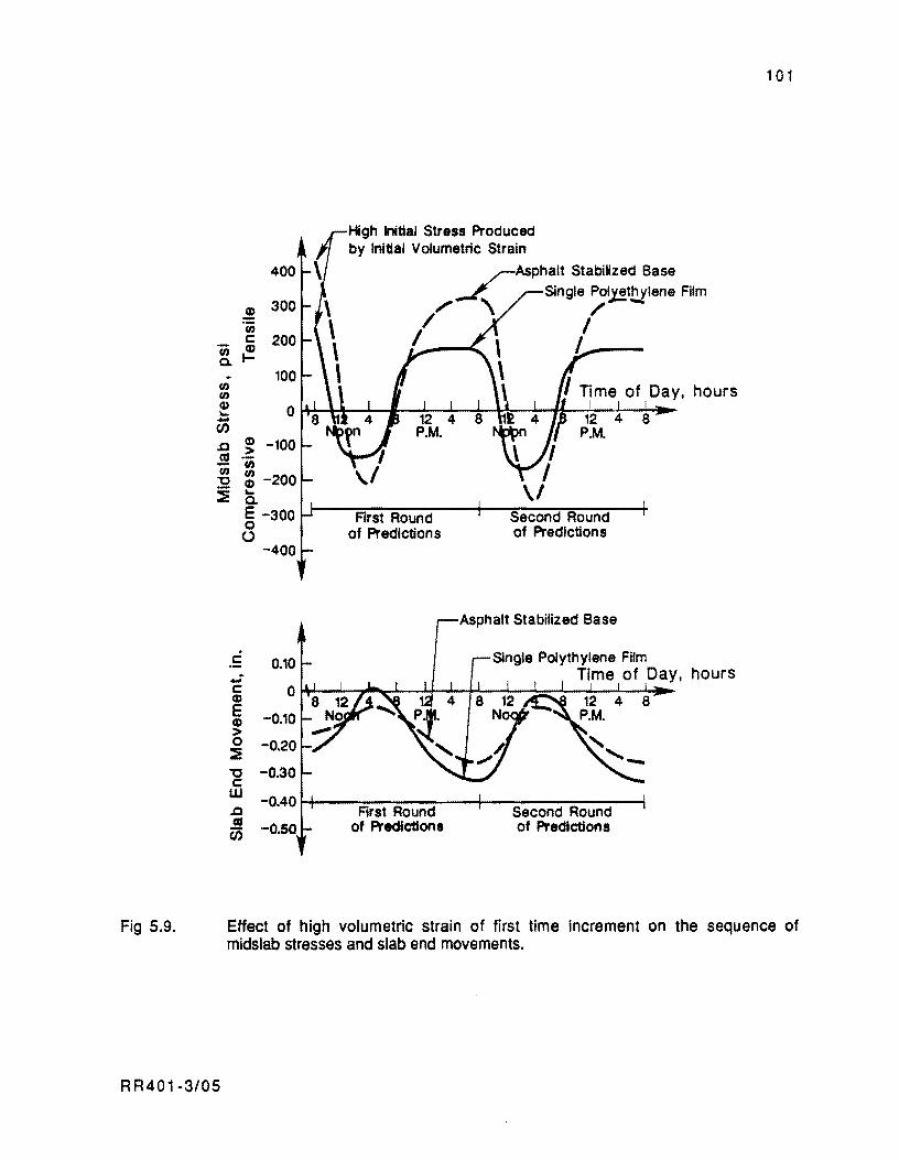
Fig 5.9.
400
,! 300 U)
c 200 'iii (I)
a. I-
- 100 U) U) Q)
0 .... -en .0
(I) -100 > ~ 'iii U) U) "0 (I) -200 :i ....
a. E -300 0 ()
-400
c 0.10 .: c 0 (I)
E -0.10 (I) > 0 -0.20 :! "0 -0.30 c W ..c -0.40 as -O.SO CiS
High Initial Stress Produced by Initial Volumetric Strain
.rAsphalt Stabilized Base .-I':.. Single Po~thylene Film
", \ / -/ I
/ I'~-
First Round of Prediction s
First Round of Predictions
Second Round of Predictions
Asphalt Stabilized Base
Single Polythylene Film Time of Day, hours
Second Round of Predictions
8
101
Effect of high volumetric strain of first time increment on the sequence of midslab stresses and slab end movements.
R R401-3/05
102
SUMMARY
In this chapter, the effect of the variables associated with the application of prestress
forces has been incorporated in the modeling of PCP behavior.
For the initial period of predictions considered in this study, the effect of prestress
force applications on the sequence of movements and stresses due to other factors is introduced
by applying the contraction produced by the post-tensioning in the time increment when the
prestress force is applied. Thus, the prestress compression is superimposed onto the friction
restraint stresses due to the contraction. It has been shown that, shortly after post
tensioning, the effect of the prestress is to shift the cycle of friction stresses due to daily
temperature changes an amount equal to the precompression applied at the slab ends. Such
prediction of behavior could not be obtained if elastic friction forces were assumed beneath the
slab.
For prediction periods after the initial period. the equations for determining the
prestress losses up to the beginning of such periods have been established. The superposition
of the prestress level after losses on the cycle of friction restraint stresses is valid, since the
friction forces are assumed to develop independently of the prestress during these periods.
RR401-3/05
CHAPTER 6. DESCRIPTION OF COMPUTER PROGRAM PCP1
Program PCP1 is the first program developed for studying the mechanistic behavior of
PCP slabs considering the inelastic nature of the slab base friction forces. This chapter is
intended to provide a brief discussion on the use and operation of the program, as well as a
description of the data, and input variables and an interpretation of the program output. The
program is written in FORTRAN 77 so that it may be easily adapted to any computer system.
The compile time for the program is less than 6 seconds. The storage requirement for the
program presently is 66500 locations.
The cost per run for PCP1 depends on the characteristics of the problem analyzed. I.e.,
the nature of the friction versus movement relationship, the variation of concrete strength
with time. the number of periods of analysiS specified per run, and the number of
temperatures input for the initial period at 2-hour intervals. However, the execution time
depends primarily on the number of iterations to achieve convergence, for a specified
tolerance level, in the loop for determining friction restraint stresses. The number of
iterations is particularly dependent on the slab length and the number of elements into which
the slab is divided for analysis. A typical run of 3 periods for a 240-foot divided in 50
elements would take approximately 8 seconds to run. This figure represents a very favorable
indicator of the program's efficiency.
INTRODUCTION TO PCP1
The primary objective of the PCP1 Computer Program is to provide engineers with a
design tool for PCP slabs. Since PCPs are designed for zero cracks, the slabs are considered by
the program as solid plates without discontinuities. The capabilities of PCP1 permit analysis
of the effect of time and different environmental conditions on the slab responses and the
prestress magnitude.
The approach inside PCP1 consists of simulating deflections, movements, and stresses
occurring in the slab during an initial analysis period at 2·hour intervals; and for two or
more subsequent 24-hour periods, also in 2-hour intervals. The predictions for the initial
period start from the setting hour, which is specified by the user, and continues through the
number of temperatures input by the user. In addition to the setting hour, the ~Iab middepth
RR401-3/06 103
104
temperature should also be supplied by the user. Curing temperature and curing hour are
used by PCP1 as reference values for computing daily and seasonal temperature variations and
other time dependent variables, Le., concrete strength, shrinkage, etc. For analysis periods
different from the initial period. the prediction intervals are started at the specified number
of days after curing. The analysis interval for this case extends for almost 24 hours, from 8
AM until 6 AM the next morning. The user should input temperature data consisting of slab
middepth temperatures and top to bottom temperature differentials for twelve two-hour time
increments.
The approach inside PCP1 of predicting slab responses at specific periods allows
flexibility in the use of the program for design. The user is permitted to search for the most
critical condition for the design element considered. This program's flexibility is
demonstrated for the reader in a design example shown in Chapter 8.
PROORAfv1 OPERATIO'J
The PCP1 Computer Program contains the main program, PCP, and seven subroutine
subprograms. Within PCP1, the main program is followed by the subprograms, arranged in
order of execution, as follows: TITLE, FREST, ITER, TIDEVAR, FRIC, COMP, and CURL.
The main program,PCP, performs a series of tasks by organizing the operation of the
subprograms according to the flow diagram shown in Fig 6.1. The different subroutines and
procedures shown in this figure are subsequently explained.
First, PCP reads the problem's general data. For convenience and help in identifying
input errors, the program makes an echo-print of the data at the beginning of the run. The
general data are categorized in the following types: problem identification, problem
definition, concrete properties, concrete compressive strength versus age relationship,
friction coefficient versus displacement relationship, stiffness of the slab support, and
properties of the prestressing steel.
After reading these general data, PCP reads the temperature data for the initial period.
These data includes curing hour and curing temperature, the sequence of slab middepth
temperatures, top to bottom temperature differentials, and time and amount of prestress
applied at each post-tensioning stage. The program's input data are discussed in more detail
in subsequent sections of this chapter.
R R401-3/06
RR401-3/06
Compute profiles of movement and friction restraint stresses from friction submodel 1
Redefine new imtial condition after reversal i for movements and stresses: Z xi & f xi Ec
ubroutlr,e FAEST
Compute profiles of movement and friction restraint stresses from friction submodel 2
ubroutlne FAEST
Print profiles of slab stresses. movements and vertical deflections
A
105
(continued)
Fig 6.1. General flow diagram of computer program PCP1.
106
RR401-3/06
Read temperature data for nod considered
Assume initial stressless condition
Determine prestress level after losses for period considered
Compute stress to beggining of period
Fig 6.1. (continued)
Redefine new initial condition after
reversal i for movements tf . Z xi & f xllEc
107
After reading the data for the initial period, PCP proceeds to determine the sequence of
pavement responses for this period, at 2·hour intervals, starting from the curing hour. For
each time increment, PCP calls subroutine TIDEVAR for getting estimates of concrete elastic
modulus, shrinkage, and radius of relative stiffness of the slab. TIDEVAR, in turn, makes use
of subroutine COMP for obtaining estimates of concrete compressive strength as a function of
time. Subsequently, PCP computes the strain increment in the longitudinal direction due to
temperature, shrinkage, and prestress force application, for the time increment considered.
Then, PCP determines if the strain increment results in a reversal of movements with
respect to the movements experienced by the slab in the previous time increment.
The next major step involves the estimation of the profiles of longitudinal movement
and stress of the slab points, from the friction submodels described in Chapter 4. Submodel 1
is applied if the slab is contracting or expanding (away from maximum or minimum
temperatures of the period) and stresses of one nature develop along the entire slab, either
tensile or compressive. Submodel 2 is applied if the slab is reversing movements near
maximum or minimum temperatures and tensile and compressive stresses develop at the same
time in different locations along the slab length.
For estimating movement and friction stress profiles, PCP resorts to subroutines
FREST and ITER to handle the iterative procedures. Once longitudinal movements and friction
stresses have been estimated, if prestress forces are applied by the time of analysis, PCP
superimposes the corresponding precompression to the friction stress profiles.
The PCP program then calls subroutine CURL to determine curling deflections and
stresses from the temperature differential of the time increment analyzed. The expressions in
subroutine CURL for estimating curling deflections and stresses are those obtained by
Westergaard solving the curvature differential equation of a slab with an infinite edge and
extending infinitely in the direction perpendicular to the edge (Ref 42). The differential
equation and its solution are presented in Appendix A. Finally, PCP prints, for the time
increment considered, the profiles of longitudinal movements, friction coefficients, concrete
stresses produced by friction and prestress, and vertical curling deflections and stresses.
This sequence is repeated consecutively by PCP for all time increments of the initial period.
Once the analysis of all time increments of the initial period is completed, PCP starts
reading the data for the next time period. First, PCP reads the number of days since curing
when this analysis period starts. Then, it reads the sequence of twelve middepth temperatures
and temperature differentials for 'the 24 -hour period.
R R401·3/06
108
Immediately, for the total prestress specified in the initial period, PCP calls
subroutine TIDEVAR for computing estimates of steel relaxation, concrete creep, and
shrinkage occurring since the last time of prestress force was applied, until the beginning of
this period. These estimates are subsequently used for computing prestress losses and the
prestress level of the strands, after losses, for the period analyzed.
Next, PCP superimposes on the friction restraint stresses thus obtained the level of
prestress, after losses, effective during this period. Finally, as for the initial period, PCP
calls subroutine CURL for determining the curling stresses and deflections for the
temperature differentials of this period. Then, the program reports sequentially, for each
time increment analyzed, the profiles of longitudinal movement along the slab, friction
coefficient, concrete stresses produced by friction and prestress, and curling deflections and
stresses. This same procedure is repeated for all subsequent periods to be investigated. The
user should input for each period the time since curing when the period starts and the
sequence of temperature data. When the program attempts to read the time since curing of a
new period, after solving for all the desired periods, and finds a blank card, PCP assumes that
the run of all periods is complete and execution is terminated.
A complete listing of computer program PCP1 is included in Appendix D.
PROGRAM INPUT DATA
The format used for inputting data into the program is arranged as conveniently as
possible. The input data may be categorized into ten different types: problem identification,
problem definition, concrete properties, concrete compressive strength versus age
relationship, friction coefficient versus displacement relationship, k-value of slab support,
steel properties, sequence of temperature data for initial period, time and amount of prestress
applied in each post-tensioning stage during the initial period, and sequence of temperature
data for subsequent periods. The format for inputting data into the program is included in
Appendix B. The codification of an example problem presented in Chapter 8 is included in
Appendix C.
The input variables for each data category are as follows.
R R40 1 -3/06
109
Problem Identification Input Variable
VECT081 contains alphanumeric information to identify the problem, i.e., project
location, date, user's name, etc.
Problem Definition Varjables
.Q..1.. defines the pavement slab length in feet. This value is in the range of 10 to 40 feet
for conventional jointed pavements (JCP or J8CP) and from 100 to 800 feet for prestressed
concrete slabs (PCP).
Jl defines the thickness in inches of the concrete slab. PCP thicknesses range from 6
inches for highway pavements up to 8 inches for airport pavements. likewise, this value is
in the range of 8 to 14 inches for jointed reinforced pavements.
til.l..O. represents the number of elements to which the slab is divided for analysis in the
longitudinal direction. A relatively large number of elements should be specified so that the
program algorithm may converge to a reasonable tolerance level. The integer number of 2-
foot-long elements fitting into the slab length is an adequate rule of thumb for selecting the
value of this parameter.
NMAX identifies the maximum number of iterations to prevent excessive computation
in those problems in which the program finds difficulty in converging within the desired
tolerance level. Most PCP problems should close to a reasonable tolerance within 50
iterations. However. the program efficiency permits up to 100 iterations to be specified
without a significant increase in the CPU time for a given run.
I..QL. refers to the relative closure tolerance within consecutive iterations and should be
expressed in percent. If it is unreasonably small, closure may be difficult to achieve. For
most PCP slab problems. a value of one percent is satisfactory.
Concrete Properties Characteristjcs
ALTOT is the variable representing the concrete thermal coefficient (inch/inch-OF).
The value of this parameter is primarily dependent on the coarse aggregate type and moisture
content of the concrete. The literature reports, for saturated concrete, minimum values for
this term in the order of 3 x 10⁻⁶ inch/inch-oF for limestone aggregate concrete and
88401-3/06
110
6 x 10- 6 inch/inch-o F for silicious aggregate concrete (Ref 51). For summer dry
conditions, thermal coefficients may be in the order of 4 x 10⁻⁶ inch/inch-oF for limestone
and 7 x 10⁻⁶ inch/inch-oF for silicious aggregate concrete. The fluctuations of joint width
expected between PCP slabs are governed, to a great extent, by the concrete thermal
coefficient.
ZTQT defines the final or total value of concrete drying shrinkage strain. Values of
final shrinkage for ordinary concretes are generally within the range of 0.0002 to 0.0007
inch/inch, depending on initial water content, ambient temperature and humidity conditions,
and the nature of the aggregate (Ref 51). Highly absorptive aggregates, such as some
sandstones and slates, result in shrinkage values twice those obtained with less absorptive
materials such as granites and some limestones. For the purpose of design, shrinkage strain
may be assumed to be about 0.0002 to 0.0004 for the concrete mixes usually used in highway
and airport PCP.
~ is the concrete unit weight (in pcf). Typical values of this parameter for normal
weight concrete ranges between 140 and 150 pct.
f..B. is the variable which defines concrete's Poisson's Ratio. For most portland cement
concretes, the value of this variable normally ranges between 0.20 and 0.25 with a value of
0.20 being cammon. A default value of 0.20 is assumed by the program if this term is not
input by the user.
CREEP represents the ultimate creep coefficient. Creep magnitude in portland cement
concrete varies with gradation of concrete aggregate, particle shape, aggregate type, cement
content, water-cement ratio, concrete density, curing, age at loading, load intensity, etc. An
ultimate creep coefficient between 2.3 and 2.5 is suggested for computing creep associated
strains of PCP slabs (Ref 51). A default value of 2.35 is assumed by the program in case this
term is not provided by the user.
Age Versus Compressive Strength Relationship
KK. AGEU(I). and CQMP(I) are the variables containing the age versus compressive
strength relationship of concrete. KK represents the total number of points supplied for the
relationship. CQMP(I) is the compressive strength, in psi, of point I at the corresponding age
AGEU(I).
R R401 -3/06
111
This relationship can be determined from compressive strength tests performed on
cylindrical specimens at different ages according to the procedures described in ASTM C39
or AASHTO T22, T140 (Refs 26 and 56). If the complete relationship cannot be determined
from tests, PCPl can generate it from recommendations given by the US Bureau of
Reclamation. In this case, KK should be specified into PCPl as 1, and into AGEU(I) as 28 days,
and COMP(l) should contain the 28th day compressive strength as obtained from the standard
cylinder tests.
Slab Versus Base Frictjon Curve (U-Z Relationship)
Ml. ZU(I). and UU(I) are the variables representing the friction coefficient versus
displacement relationship. Ml represents the number of points supplied to describe the
relationship. ZU(I) is the displacement in inches of the Ith point. and UU(I> is the
corresponding friction coefficient. Three types of friction relationships can be input into the
program: a straight line, an exponential curve. and a multi-linear curve. The desired
relationship is specified by the control variable Ml, in which. a value of one, two or greater
than two, indicates that the curve is a straight line or an exponential or multi-linear
relationship, respectively. In the case of a straight line. only one point is required to define
the curve. This is the point where sliding occurs. In the case of an exponential curve, the
program uses a function of the following form:
where
Z
U
a
1 3
U = Umax (Z/a)
=
maximum friction coefficient,
movement of a given point of the slab.
friction coefficient corresponding to movement Z. and
movement at sliding point.
(6.1 )
The maximum friction cC'efficient and the movement at sliding are, then, the variables
to input in this case. If exponential or multi-linear curves are used, the first point to input
R R401-3/06
112
should contain the origin: ZU(1) = 0 and UU(1) = O. Otherwise, the program prints an error
message and the execution is aborted. In case an exponential function is specified (M1=2), the
first point should contain the origin and the second the movement for which sliding occurs and
the maximum friction coefficient.
Finally, regardless of the curve type used for specifying the slab base friction
properties, the mirror image of the curve is used for movements reversing direction, with
the origin redefined where the reversing movement starts occurring. This implies that only
one portion of the curve has to be supplied; the remainder is generated by the program.
Figure 6.2 shows the curve types considered by PCP1.
properties of Slab Support
.5K is the variable that defines the modulus of reaction on top of the supporting layer of
the slab, in psi per inch of deflection (psi/inch). The determination of this variable can be
done from in-place loading tests on the representative supporting layer or from correlation
with other field tests or laboratory tests on the supporting base material.
Normally, rigid pavements are provided with one or two base layers of well compacted
granular material between the roadbed soil and the rigid pavement. It is costly and sometimes
impossible to run plate loading tests on these materials as the loads required to obtain a given
deflection on the top layer may be extremely high. To circumvent this difficulty, a method for
obtaining the modulus of reaction on top of the upper base layer (composite k-value) has been
proposed by Elkins and McCullough (Ref 52), for the design of continuously reinforced
concrete pavements (CRCP). The composite k-value can be estimated from the modulus of
subgrade reaction, obtained from plate loading tests on the roadbed soil and corrected to
account for the effect of as many layers as provided between the subgrade and the slab. This
procedure is recommended as a practical method for defining the value of this parameter.
Steel properties
s..s. defines the strand spacing in inches. If the program reads a value of zero for this
variable, it assumes that steel properties are not required for the problem considered.
Likewise, the program assumes that data will not be provided for the category type in which
the sequence of post-tensioning applications for the initial period is specified.
RR401-3/06
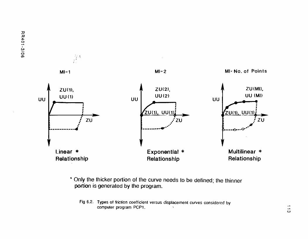
:D :D
"'" o ...... •
U) """o en
UU
MI=1
ZU(1),
UU (1)
. / ~.
• • • • • • • • : ZU • • • ••••••••••••• -4
Linear * Relationship
UU
MI=2
ZU(2), UU (2)
• • • • - - --., UU(1)f :JIll
. ......... .-.. /ZU • p •
Exponential * Relationship
UU
MI; No. of Points
ZU (MD, UU(MI)
• • • • ZU1l1_J)U(1)~ ...
.: ZU .JII •
•••• t()a: •• Ot* ..
Multilinear * Relationship
* Only the thicker portion of the curve needs to be defined; the thinner portion is generated by the program.
Fig 6.2. Types of friction coefficient versus displacement curves considered by computer program PCP1.
w
114
.s..A. represents the nominal area of the tendons in inch2. The tendons commonly
specified in PCP are 7·wire strands with 0.6 inch nominal diameter and a nominal area of
0.216 inch2. From this value and the strand spacing, PSCP1 computes the percent
reinforcement the steel represents of the pavement cross section.
EEY. is the steel yield stress in ksi. A default value of 230 ksi. which is typical of high
strength steel, is assumed by PSCP1 if a value for this term is not provided by the user.
E.S. is the steel elastic modulus in psi. Values between 25 x 106 and 28 x 106 psi
are typical of high strength steel working in the elastic range. PSCP1 assumes a default value
of 28 x 106 psi if a value is not supplied for this parameter.
~ defines the steel thermal coefficient. A value of 5 x 10.6 is recommended for
use in design. This value is assumed as the default by PSCP1 in case a value is not supplied for
this term.
SeQuence of Temperature Data for Initial Period
NPEB defines the number of pairs of slab middepth temperatures and top to bottom
temperature differentials provided at 2-hour intervals. for the initial period.
C U 8 H represents the setting hour in the scale of 0 to 24 hours from which PSCP1
starts the predictions for the initial period of analysis. The program uses this variable as the
reference time for evaluating time dependent parameters.
CUBTEMP is the variable defining the slab mid depth temperature of the setting hour in
degrees Fahrenheit. The program uses this value to determine temperature variations for the
time increments of the initial and subsequent periods of analysis.
ADT(I) and TDIF(I) are the variables containing the Ith pair of slab middepth
temperatures and top to bottom temperature differentials, in degrees Fahrenheit. occurring
2xl hours after the setting hour. Temperature differentials should be positive if the
temperature is higher at the top than at the bottom of the pavement. One card should be
codified per,ii8i~ of temperature data.
Values for these variables can be obtained from temperature records of existing
concrete pavements in the same climatic zone and with physical characteristics similar to
those of the one being designed. One of the predictive models of pavement temperatures
based on the theory of heat conduction through semi-infinite masses can also be used for
88401-3/06
115
defining these parameters. A model of such nature is presented by Uddin, Nazarian, et al in
Ref 41.
SeQuence of Post-tensioning Applications During Initial Period
These variables should be provided only if steel properties were specified earlier in
the corresponding data category.
f:!a represents the number of stages in which the total post-tensioning force will be
completed.
IAGE and pSm represent the time since setting, in hours, and the partial amount of
prestress per strand PS(I), in ksi, completed at post-tensioning stage I. One card containing
these variables should be codified for each stage of post-tensioning application.
Temperature Data for SubseQuent periods
J.IQA is the variable indicating the number of days elapsed since setting to the beginning
of the period considered. This variable is also used as a switch for the program to stop
execution when PSCP1 has completed the analysis of the time increments of all desired periods
of analysis. Hence, a blank card after the last temperature data input of the last period should
be used to specify that the program execution is to be terminated.
ADT(I) and TDIF(I) are the variables containing the 12 pairs of middepth and top to
bottom temperature differentials. in degrees Fahrenheit, for the 24-hour cycle of the given
period. The program assumes that the first data pair corresponds to 8 AM, the second to 10
AM, the third to 12 AM, and so on, until 6 AM of the next morning. One card should be codified
per pair of temperature data input.
,r:---
PSCP1 OUTa1r DESCRIPTION --.
The output of the PSCP1 Computer Program basically consists of two parts: (1) an
echo print of the general data and (2) a report of the profiles of longitudinal movements,
friction coefficients, prestress plus friction restraint stresses, curling stresses, and
deflections at the bottom of the slab, from midslab to the slab ends. This information is
RR401-3/06

116
reported for all 2·hour increments of all periods of analysis requested by the user. A
complete printout from PSCP1 corresponding to an example problem shown in Chapter 8 is
presented in Appendix C. Pavement responses are generated for three periods of analysis in
this example.
SUMMARY
A description of the main features of Computer Program PSCP1 has been presented in
this chapter. and some of the assumptions considered inside the program have been
emphasized. The cost per run of the program depends on the characteristics of the problem
analyzed. i.e .• the nature of the friction versus movement relationship. the variation of
concrete strength with time, the number of periods of analysis specified per run and the
number of temperatures input for the initial period of predictions at 2-hour intervals.
However, the execution time and related cost depend primarily on the number of elements in
which the slab is divided for analysis. A detailed description of the program variables, and
input data and an interpretation of the output have also been presented in this chapter. A
complete listing of Computer Program PSCP1 is included in Appendix D. The format for
inputting data into the program is included in Appendix B. The codification and run of an
example problem are shown in Appendix C.
R R401-3/06

CHAPTER 7. COMPARISON OF PREDICTIONS FROM PCP1 WITH DATA COLLECTED FROM THE McLENNAN COUNlY OVERLAY ~ACO)
Equally as important as the development of a model and mathematical techniques for
analyzing a problem is the comparison of predictions from the model with real world data. In
the first part of this chapter, some background information on the McLennan County Project.
located 15 miles north of Waco, is given as is a description of the instrumentation program for
monitoring the section. In the second part of this chapter, a statistical analysis is performed on
a set of joint openings recorded at different pavement ages and temperatures. Estimates are
obtained from this analysis of the following concrete properties:
(1 ) thermal coefficient of contraction and expansion,
( 2) ultimate shrinkage strain, and
(3) ultimate creep strain.
This analysis will permit an evaluation of the accuracy of the models inside PCP1 for
predicting long term slab movements.
Since the main contribution of this study is the incorporation of the inelastic effect of
the friction, the third part of this chapter is devoted to comparing measured and computed
longitudinal movements during temperature cycles in which consecutive cycles of slab
movements are observed. Moreover, the in-service slab base friction properties of the Waco
pavement can be inferred by comparing recorded cycles of movements at Waco with predictions
from Computer Program PCP1.
PROJECT BACKGROLI\ID
The experimental prestressed concrete overlay in Waco is located on southbound IH-35
between staiiOlls 696+00 and 749+00. Between 17 September and 20 November 1985,
eighteen 240-foot and fourteen 440-foot PCP slabs were cast. The arrangement of the slabs in
each of the southbound lanes of IH-35 and the locations of the test sections are presented in
Fig 7.1. The original pavement consisted of a 12-inch jointed concrete pavement 38 feet
width. The jointed pavement was sealed and overlaid with approximately 2 inches of asphalt
concrete pavement (ACP); subsequently a single polyethylene layer and 6-inch-thick PCP
R R40 1-3/07 117
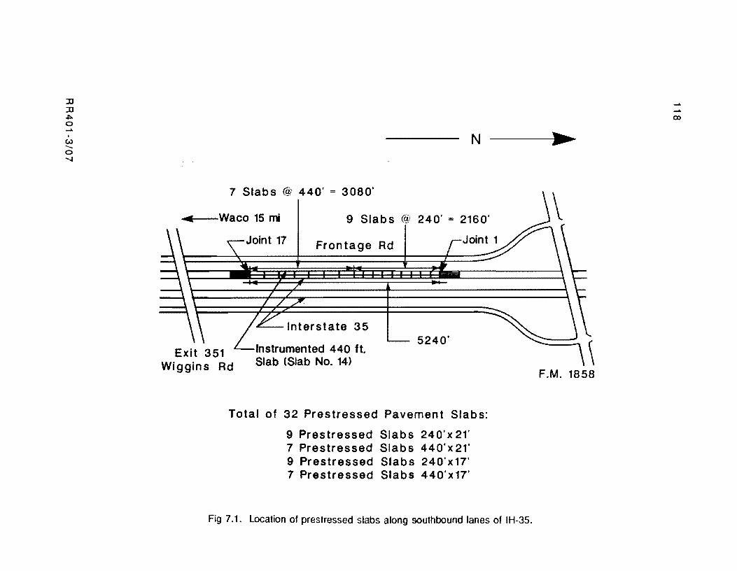
:D :D .I:>-0 .....
I
W ....... 0 .......
N
7 Slabs @ 440' = 3080'
... Waco 15 mi 9 Slabs @ 240' = 2160'
Exit 351 Wiggins Rd
Frontage Rd
£---Interstate 35
Instrumented 440 ft. Slab (Slab No. 14)
5240'
Total of 32 Prestressed Pavement Slabs:
9 Prestressed Slabs 240'x 21' 7 Prestressed Slabs 440'x21' 9 Prestressed Slabs 240'x17' 7 Prestressed Slabs 440' x 17'
Fig 7.1. Location of prestressed slabs along southbound lanes of IH-3S.
..... ..... (X)
•
F.M. 1858
11 9
slabs were placed on top. The slabs were posttensioned by applying the prestress in pockets
near midslab. This technique of central stressing was introduced for the first time with PCP in
the McLennan County Project. This technique eliminated the use of gaps between adjacent
prestressed slabs for the post-tensioning operations. Another innovation in PCP for highways
introduced in the McLennan County overlay was the use of prestress in the transverse direction.
The need of transverse prestress has been recognized in the past since commonly in-service
PCP projects have developed longitudinal cracking (Refs 10 and 11). In addition, the
transverse prestress in the Waco Project would keep the longitudinal joint closed as the tendons
of the transverse prestress would be continuous into adjacent slabs accross the longitudinal
joint. The PCP overlay in Waco was opened to traffic in December 1985. The design and
construction of the overlay is reported by Mendoza, McCullough, et al in Ref 4.
Since construction of the Waco Project, the pavement has been continuously
instrumented and monitored. An instrumentation plan for the pavement is presented in Ref 4,
and the testing program and the set of recorded data are reported by Maffei, Burns, et aHRef
53). In general. the instrumentation scheme implemented in Waco consisted of short term
instrumentation and long term instrumentation. In turn, the short term instrumentation
consisted of continuous recordings that necessitated the use of an electronic data acquisition
system. Voltage signals from thermocoples and displacement transducers were recorded by the
data acquisition device over several daily temperature cycles. Thermocouples were used to
monitor both ambient and concrete temperatures. Slab movements were monitored using
displacement transducers mounted along the pavement edge.
Most of the long term measurements consisted of mechanical measurements of joint
width at all transverse joints. These measurements were taken between reference marks on
each side of the joints using calipers and extensometers. A record of joint width accross all
jOints with time and temperature constituted the best source of information for evaluating the
concrete properties relevant to this study. For this evaluation, a regression analysis was
performed on the jOint openings. A description of the analysis, the data setup, and the
conclusions from the analysis are presented in the following section.
R R40 1 ·3/07
120
REGRESSION ANALYSIS OF THE JOINT WIDTH DATA
Regression analysis is a powerful statistical tool for identifying relationships among
variables. The relationship is formed through an equation relating a dependent or response
variable to more than one independent or explanatory variable.
The main purpose of the analysis shown herein is to determine the values of concrete
thermal coefficient and ultimate shrinkage and creep strains and to evaluate the reliability of
the models inside PCP1 for predicting long term movements. The data set used in this analysis
corresponds to the joints of the inside lane slabs which were constructed first, in the direction
north to south. The joint openings were recorded between 20 September and 10 December,
1985. Hence, inherent in the movements are shrinkage and creep deformations which for the
most part occur during the first three months of the pavement for normal concrete mixes, such
as the one used in Waco.
The pavement joints were numbered sequentially from 1 to 17 from north to south.
Number 1 was assigned to the joint on the section north end and 17 to the section south end. The
joint openings used in this analysis are reported following the nomenclature in Appendix E. As
may be evidenced from Fig 7.1, the movements of Joint 1 result from the movements of one
240-foot slab. The movements of Joints 2 to 9 result from the contraction and expansion of two
240-foot slabs. The movements of Joint 10 are the result of the movements of a 240-foot slab
and a 440-foot slab. Joints 11 to 16 move as a result of contraction and expansion of
contiguous 440-foot slabs. Finally, the movements of Joint 17 result from the movements of
one 440-foot slab.
The combined data set used in this analysis is comprised of 51 points. The data set is
reported in Appendix E. Figure 7.2 shows a plot of change in joint opening from the initial
width shown by the joints at a reference date, versus the temperature change from the
temperature at the reference date. The date at which the first opening was taken for a given
joint was defined as the reference date for the joint. Generally, the first opening reading for
each joint was taken within the first 48 hours after
construction of contiguous slabs when the final prestress had been applied on both slabs. In Fig
7.2, it is apparent that there is a trend to decreasing joint width with temperature increments.
This tendency is obviously more significant in joints between 440-foot slabs than in joints
between 240-foot slabs. The effect of time is included in this figure.
RR401-3/07
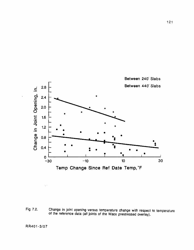
. c:
.. C> c: .-c: (1)
0. o -c: '0 -;)
c: (1)
C> c: as
2.8
2.4
2.0
1.6
1.2
0.8
.c: () 0.4
• • • • • - •
• • • • •
+
+ +
• • • I
., ·t
• •
•
•
Between 240' Slabs
Between 440' Slabs
• • • -• • •
121
o L-______ ~ ____ ~ ____ ~ ____ ~ ______ ~ __ ~ -30 -10 10 30
Fig 7.2.
RR401-3/07
Temp Change Since Ref Date Temp, OF
Change in joint opening versus temperature change with respect to temperature of the reference data (all joints of the Waco prestressed overlay).
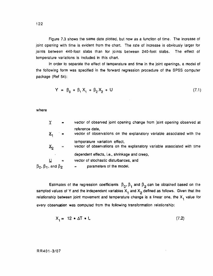
122
Figure 7.3 shows the same data plotted, but now as a function of time. The increase of
joint opening with time is evident from the chart. The rate of increase is obviously larger for
joints between 440-foot slabs than for joints between 240-foot slabs. The effect of
temperature variations is included in this chart.
In order to separate the effect of temperature and time in the joint openings, a model of
the following form was specified in the forward regression procedure of the SPSS computer
package (Ref 54):
where
y =
X1 =
~
.u = ~O' ~1' and ~2
(7.1 )
vector of observed joint opening change from joint opening observed at
reference date, vector of observations on the explanatory variable associated with the
temperature variation effect, vector of observations on the explanatory variable associated with time
dependent effects, Le., shrinkage and creep,
vector of stochastic disturbances, and
parameters of the model.
Estimates of the regression coefficients ~O' ~1 and ~2 can be obtained based on the
sampled values of Y and the independent variables X1 and X2 defined as follows. Given that the
relationship between joint movement and temperature change is a linear one, the X1 value for
every obseNation was computed from the following transformation relationship:
X1 = 12. ~T • L (7.2)
R R401-3/07
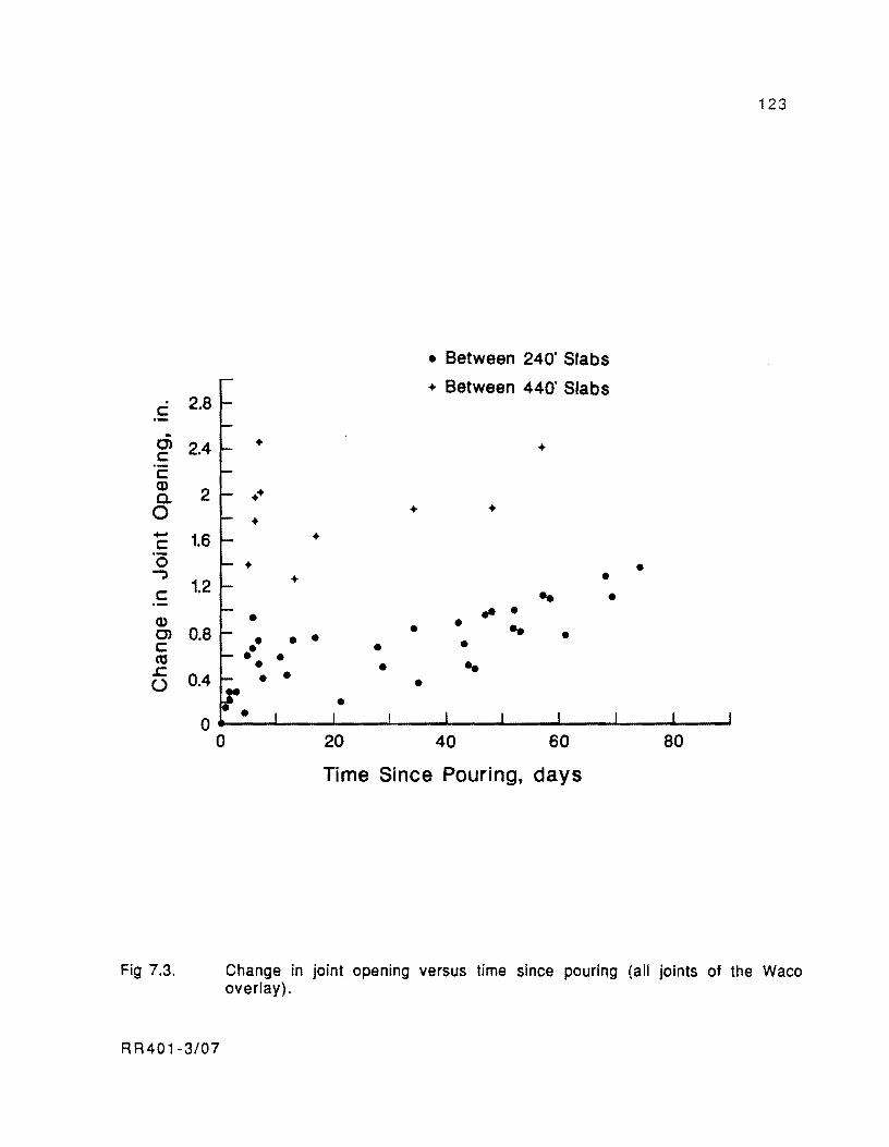
c: 2.8
. (J) 2.4 c: .-c: Q)
2 a.. 0 - 1.6 c: 0 -;)
c: 1.2
Q) (J) 0.8 c: Cd .c 0.4 ()
0 0
Fig 7.3.
RR401-3/07
123
• Between 240' Slabs
+ Between 440' Slabs
+ +
++ + +
+ +
+ • + • .. • .. • • • • .. • • • • • •• • • • • • • • • •
20 40 60 80
Time Since Pouring, days
Change in jOint opening versus time since pouring (all joints of the Waco overlay).

124
where
ilT OIl temperature change, in degrees Fahrenheit, with respect to the reference
temperature of the joint,
L = summation of slab halves at both sides of the joint considered, in feet.
The transformation relationship for the explanatory variable X2
, associated with time
dependent effects, should have the form of the equations for evaluating creep and shrinkage,
shown in Chapter 5 and Appendix A, respectively. After attempting a regression equation with a
transformation function similar to the one shown for shrinkage. a better result was obtained
with an expression similar to the one for creep:
where
L
t = =
= 12 • L 10
to.50 + 1
as defined before, and
time since reference date, in days.
The estimated equation using SPSS is
Y 0.02355 ·4.22 x 10-6 X + 6.291174 X 10⁻⁴
X = 1 2
RR401-3/07
(7.3)
(7.4)
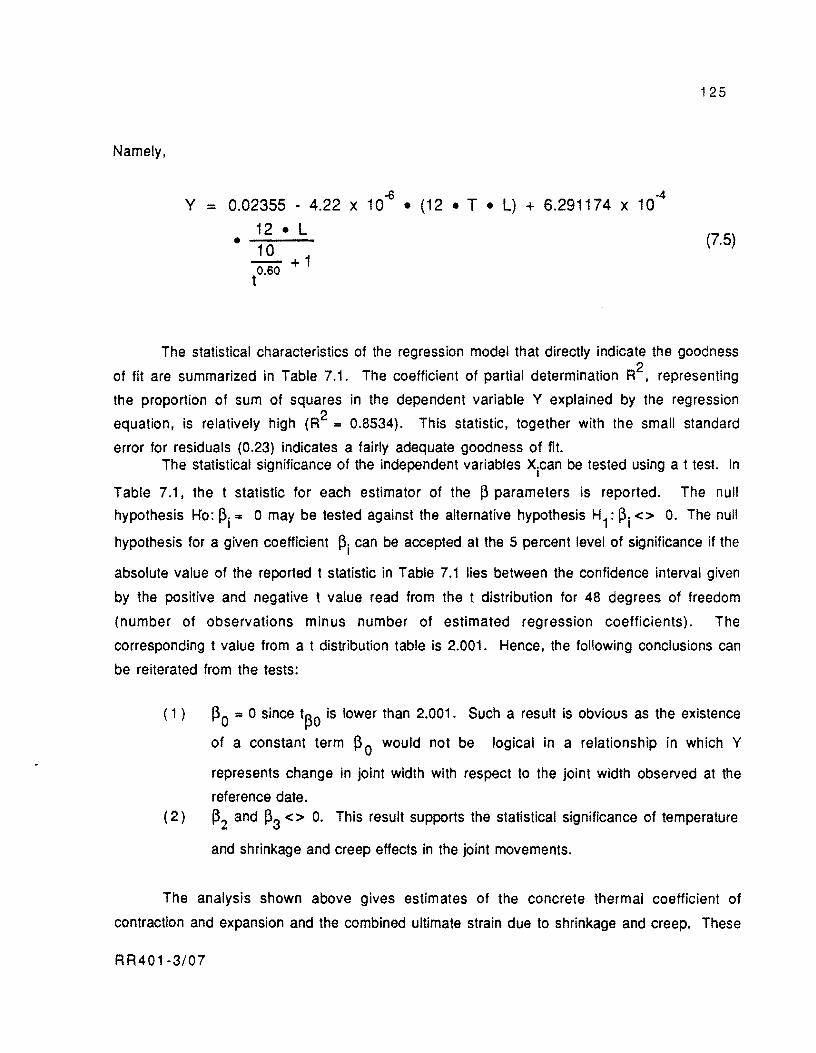
Namely,
~ 4 Y = 0.02355 - 4.22 x 10 • (12 • T • L) + 6.291174 x 10
• 12 • L 10
to.60 + 1
125
(7.5)
The statistical characteristics of the regression model that directly indicate the goodness
of fit are summarized in Table 7.1. The coefficient of partial determination R2, representing
the proportion of sum of squares in the dependent variable Y explained by the regression
equation, is relatively high (R2 = 0.8534). This statistic, together with the small standard
error for residuals (0.23) indicates a fairly adequate goodness of fit. The statistical significance of the independent variables xican be tested using a t test. In
Table 7.1, the t statistic for each estimator of the ~ parameters is reported. The null
hypothesis Ko: ~i'" 0 may be tested against the alternative hypothesis H1: ~i <> O. The null
hypothesis for a given coefficient ~i can be accepted at the 5 percent level of significance if the
absolute value of the reported t statistic in Table 7.1 lies between the confidence interval given
by the positive and negative t value read from the t distribution for 48 degrees of freedom
(number of observations minus number of estimated regression coefficients). The
corresponding t value from a t distribution table is 2.001. Hence, the following conclusions can
be reiterated from the tests:
( 1 ) ~O = 0 since t~o is lower than 2.001. Such a result is obvious as the existence
of a constant term ~ 0 would not be logical in a relationship in which Y
represents change in joint width with respect to the joint width observed at the
reference date. (2) ~2 and ~3 <> O. This result supports the statistical significance of temperature
and shrinkage and creep effects in the joint movements.
The analysis shown above gives estimates of the concrete thermal coefficient of
contraction and expansion and the combined ultimate strain due to shrinkage and creep. These
RR401-3/07

126
terms are the parameters ~1 and ~2 in model 7.1, respectively. A thermal coefficient of
4.22 x 10⁻⁶ inch/inch.oF is fairly normal for the limestone river gravel aggregate concrete
used for the McLennan County overlay. An ultimate strain for the combined effect of shrinkage
and creep of 6.2911 x 10.4 inch/inch is also very reasonable as the ultimate strain of
each separated factor should be in the order of 3 x 10⁻⁴ inch/inch as indicated in the
description of the PCP1 Computer Program input variables in Chapter 6.
Final observations regarding the analysis shown above are the following:
( 1 ) It was not possible to obtain separate estimates of ultimate shrinkage and creep
strains as the observations started being recorded after the total prestress had
been applied. The effect of shrinkage and creep is, therefore, combined in the
recorded joint widths. If some readings had been taken before prestress forces
were applied in the slab, the effect of creep would not be included in some of the
data. In this case, by contrasting joint widths before and after creep strains had
occurred. it would have been possible to make a separate evaluation of these
. parameters. (2) When regression model 7.1 was run defining the term X2 similarly to the
RR401-3/07
shrinkage model shown in Appendix A, the R2 statistic of the regression decreased to 0.825 from the 0.8534 obtained for the term X2 defined in a form
similar to the creep equation (Eq 7.3). Likewise, the standard error of the residuals increased from 0.23 to 0.281. The term X2 was defined in this case
for each observation as follows:
=
where
12 • L
26eo.360
---+ 1 t
Land t are as defined earlier, and
o slab thickness in inches.
(7.6)
127
This shows that the creep model represents the collected data more faithfully than the
shrinkage model. However, the statistics indicating goodness of fit are fairly adequate in both
cases (high R2 and low standard errors). Hence, it can be concluded that the shrinkage and
creep models are fairly reliable. Graphical evidence of this is provided in Fig 7.4 in which the
data points, after removing the temperature effect, are plotted together with the estimated term for ~2 • X2 in Eq 7.5. From this chart, it is evident that the creep model inside PCP1 would
provide reasonable predictions of time dependent movements of the joints. The same conclusion
is valid for the shrinkage model.
COMPARISON OF RECORDED CYCLES OF MOVEMENT VERSUS PREDICTED MOVEMENTS FROM COMPUTER PROGRAM PCP1
In this part of the analysis, joint movements measured over several daily temperature
cycles are compared with the corresponding predictions from Computer Program PCP1. The
recorded movements were obtained from 48-hour sessions of electronic instrumentation
installed in a 440-foot slab at Waco. Data for the 240-foot slabs are reported by Maffei,
Burns, et al (Ref 53) and their analysis may lead to conclusions very similar to those obtained
herein.
The third 440-foot outside lane slab from south to north (slab No. 14 in Fig 7.1) was
instrumented in February and April 1986, two and four months respectively after being
constructed. During the first session of readings, thermocouples were placed in the outside lane
shoulder, one embeded in the concrete at middepth and the other in the shade outside the slab.
The locations of the thermocouples along the slab length are illustrated in the sketch at the top of
Fig 7.5. Figure 7.5. shows plotted ambient and concrete temperatures (in OF) versus hour of
the day. Slab movements were measured (at the same times as temperatures) through
displacement transducers mounted along the pavement edge in two locations: the slab end and 55
feet from the end toward the center. The transducers' locations are illustrated in the diagram at
the top of Fig 7.6. In this figure, the trend of recorded movements versus the time of the day is
shown. Two facts are relevant from a joint analysis of Figs 7.5 and 7.6:
( 1 ) The maximum temperature rise for the first cycle occurs between 8 AM and 4
PM. The slab middepth temperature increases from 59.5 of up to 69.5 of or
a temperature increase of nearly 10°F in Fig 7.5. Between these hours, the
R R40 1-3/07
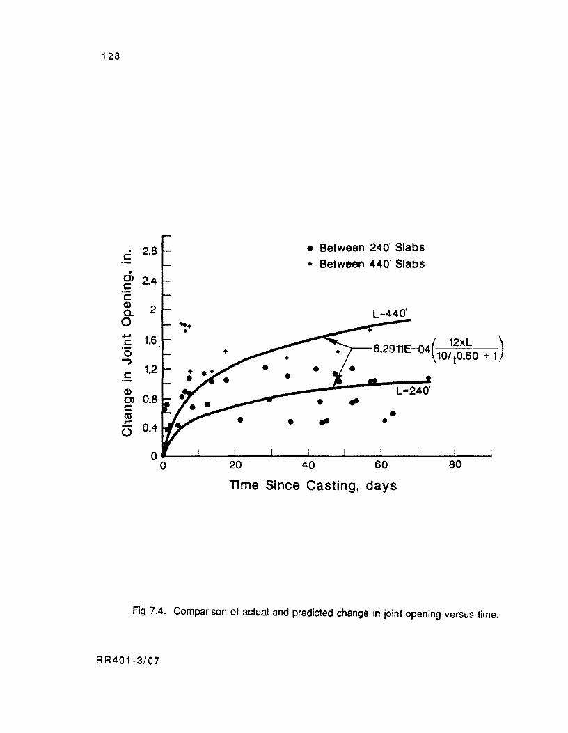
128
. 2.8 c: ~
CJ) 2.4 c: .-c: Q)
2 a. 0 - 1.6 c: '0 ..., c: 1.2
Q) 0.8 CJ)
c: ttl .c 0.4 U
°
..... + +
+
°
• Between 240' Slabs
+ Between 440' Slabs
L=440'
( 12xL )
6.2911E-04 101 to.60 + 1
• • fII
• •
20 40
• •
L=240'
Time Since Casting, days
Fig 7.4. Comparison of actual and predicted change in joint opening versus time.
R R40 1-3/07
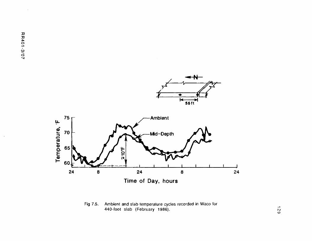
:IJ :IJ ,f:>. o .... w ...... o ......
75.-LL
~ 70 ::::J ... as ~
~ 65 E Q)
I- 60
24
,.....-----. 55ft
~Ambient
8 24 8
Time of Day, hours
Fig 7.5. Ambient and slab temperature cycles recorded in Waco for 440-foot slab (February 1986).
24
I'\)
to
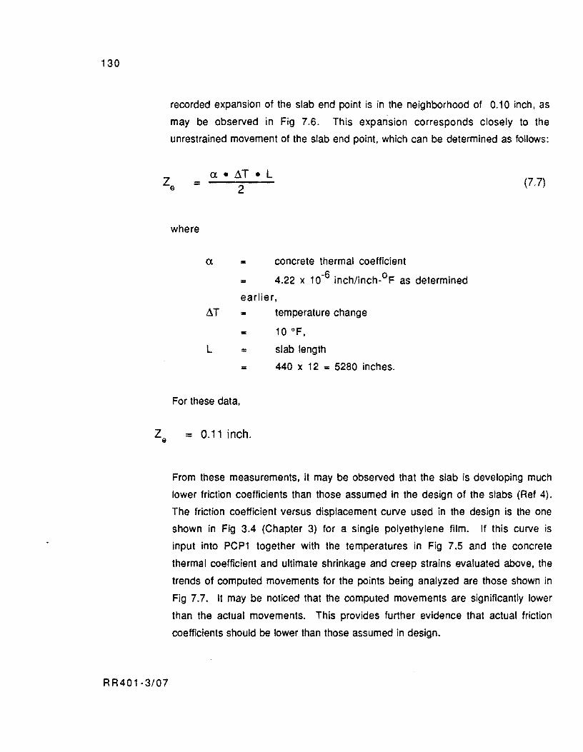
130
recorded expansion of the slab end point is in the neighborhood of 0.10 inch, as
may be observed in Fig 7.6. This expansion corresponds closely to the
unrestrained movement of the slab end point, which can be determined as follows:
=
where
a • 6T • L 2
= concrete thermal coefficient
= 4.22 x 10⁻⁶ inch/inch-oF as determined
earlier,
6 T = temperature change
= 10°F,
L = slab length
= 440 x 12 = 5280 inches.
For these data,
(7.7)
Ze = 0.11 inch.
RR401-3/07
From these measurements, it may be observed that the slab is developing much
lower friction coefficients than those assumed in the design of the slabs (Ref 4).
The friction coefficient versus displacement curve used in the design is the one
shown in Fig 3.4 (Chapter 3) for a single polyethylene film. If this curve is
input into PCP1 together with the temperatures in Fig 7.5 and the concrete
thermaJ coefficient and ultimate shrinkage and creep strains evaluated above, the
trends of computed movements for the points being analyzed are those shown in
Fig 7.7. It may be noticed that the computed movements are significantly lower
than the actual movements. This provldes further evidence that actual friction
coefficients should be lower than those assumed in design.
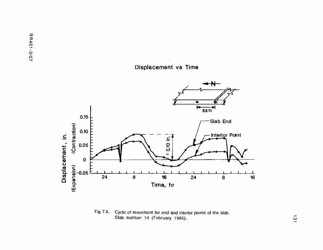
:D :D .,.. a ...... w -a ...."
-5 ~ • 0
c as .... -c ..... 0 c U CD E CD o as
0.15
0.10
0.05
a
Displacement vs Time
/ 1,. ....-N
t- ~ IT 55ft
Slab End
Interior Point ......
B-en
c o ·us -0.05 I...C --L--1-JL-.L-.....I.--'---L---I_.L.-...L-.......L..--L.---L-JL...-..I...-....I.-......I---L.---'-_'--..I...-......
c 24 8 16 24 8 16 as C e- Time, hr w
Fig 7.6. Cycle of movement for end and interior points of the slab. Slab number 14 (February 1986). w
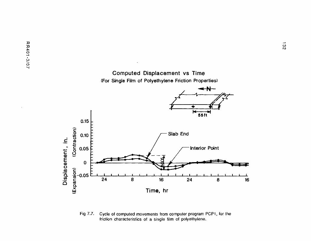
::0 ::0 ~ o ...... w ....... o -...j
-c: o ~ o c: co ... -c:
- 0 c 0 CD E CD o as c:
Computed Displacement vs Time (For Single Film of Polyethylene Friction Properties)
---N
(L.~ ~ 14
55ft ....
0.15
0.10
0.05 Interior Point
o
Ci U)
(:) .~ -0.05 L· --L-2..14---1l---L.-L--LS---l_L-..L-...I.16........JL-L-..L-2...J.4-L-.L-......I.-....L---L.--L.--I.-I-co a.
S 16
)(
w Time, hr
Fig 7.7. Cycle of computed movements from computer program PCP1, for the friction characteristics of a single film of polyethylene.
..... w f\)
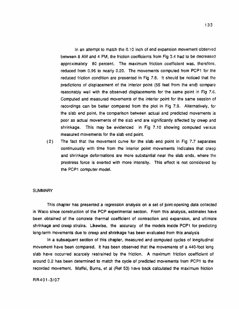
133
In an attempt to match the 0.10 inch of end expansion movement observed
between 8 AM and 4 PM, the friction coefficients from Fig 3.4 had to be decreased
approximately 80 percent. The maximum friction coefficient was, therefore,
reduced from 0.96 to nearly 0.20. The movements computed from PCP1 for the
reduced friction condition are presented in Fig 7.8. It should be noticed that the
predictions of displacement of the interior point (55 feet from the end) compare
reasonably well with the observed displacements for the same point in Fig 7.6.
Computed and measured movements of the interior point for the same session of
recordings can be better compared from the plot in Fig 7.9. Alternatively, for
the slab end pOint, the comparison between actual and predicted movements is
poor as actual movements of the slab end are significantly affected by creep and
shrinkage. This may be evidenced in Fig 7.10 showing computed versus
measured movements for the slab end point.
(2) The fact that the movement curve for the slab end point in Fig 7.7 separates
SUMMARY
. continuously with time from the interior point movements indicates that creep
and shrinkage deformations are more substantial near the slab ends, where the
prestress force is exerted with more intensity. This effect is not considered by
the PCP1 computer model.
This chapter has presented a regression analysis on a set of joint-opening data collected
in Waco since construction of the PCP experimental section. From this analysis, estimates have
been obtained of the concrete thermal coefficient of contraction and expansion, and ultimate
shrinkage and creep strains. Likewise, the accuracy of the models inside PCP1 for predicting
long-term movements due to creep and shrinkage has been evaluated from this analysis
In a subsequent section of this chapter, measured and computed cycles of longitudinal
movement have been compared. It has been observed that the movements of a 440-foot long
slab have occurred scarcely restrained by the friction. A maximum friction coefficient of
around 0.2 has been determined to match the cycle of predicted movements from PCP1 to the
recorded movement. Maffei, Burns, et al (Ref 53) have back calculated the maximum friction
RR401-3/07
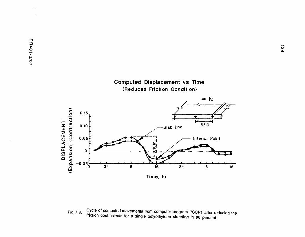
:::JJ :::JJ :,:.. 0 ......
I
W -... 0 .......
r::: 0.15 0 -I- 0
Z as 0.10 a..
W -~ r::: w 0 0.05 00
<C ...J r::: Q.. 0 0 U) U)
0 r::: as Q. -0.05 )( 0 24 W
Computed Displacement vs Time (Reduced Friction Condition)
----N / 1- ~
~.6 Slab End
14 'PI 55ft
Interior POint
8 16 24 8 16
Tim., hr
F' 7 8 Cycle of computed movements from computer program PSCP1 after reducing the Ig .. friction coeffficients for a single polyethylene sheeting in 80 percent.
...... w :,:..

Fig 7.9.
z I w...;_ \ l: c
u...: • >7, c L
o ~g !:::J9 .~ .
M(-;";'""'j , .' ! v.; ,
. . =~------~------~--------~-------T--------' : -ll. :s -0.0'3-0.01 0.03 O. 25
MEASLREG MC~EMENT (I N)
135
Computed movements from PSCP1 versus measured movements at Waco for Slab quarter point.
RR401-3/07
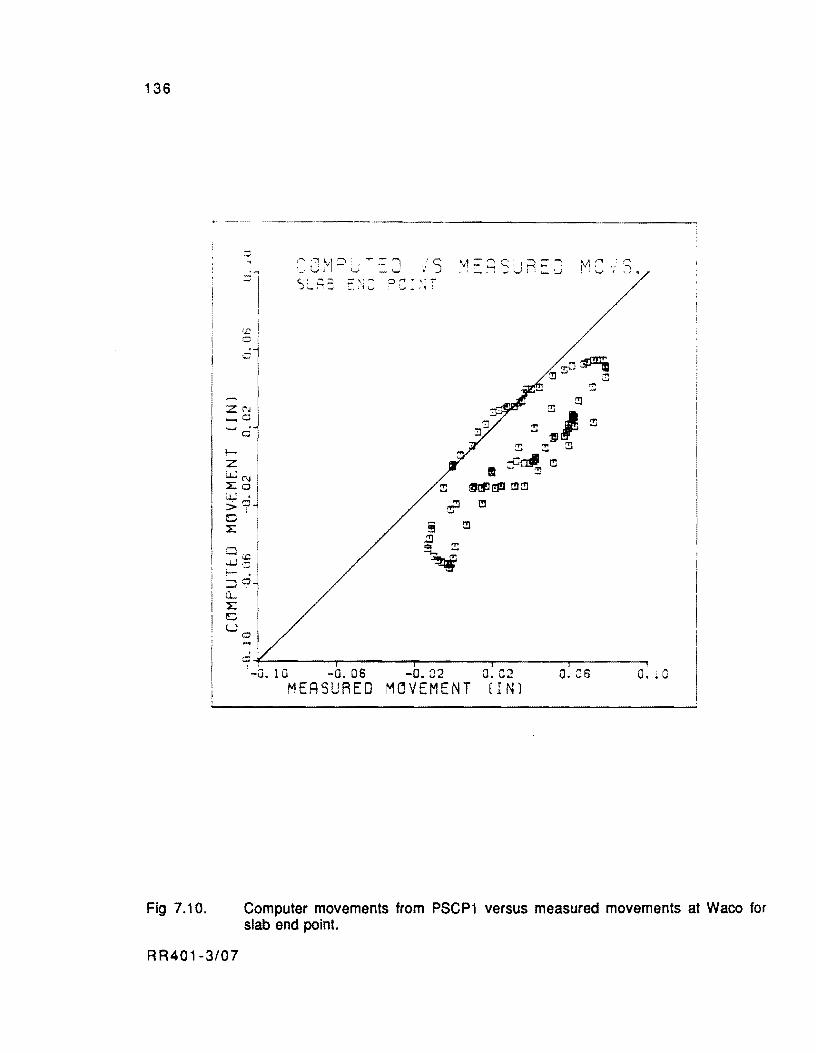
136
Fig 7.10.
o
Z ("J _0
-ci
IZ ~
4~ lJj.
, >7 o 4 I Cl:.£: w.:::; I- • -0 -' ,
CL' 4 ~ u
::1
',1 = r c: : I ~ C -: • I ~.i -' W : : '- ~ M"" .,.., I ,',:',
• '-" I ........ (I
? :' .. \; -: '..J4o ,1 .
:!I
~ :1 ~ ::!:: :!: !!l
II :9~ I!l
~ :3ttJ I!J!J [!]:!I
'!? [!]
§ [!]
~ ~ ~
O~-------r------~--------T-------~------~ l -G. 10 -0. 06 -0. 02 O. 02 O. C6 o. 10
MEASURED MOVEMENT (I N)
Computer movements from PSCP1 versus measured movements at Waco for slab end point.
RR401-3/07
137
coefficient under the slabs at Waco from a record of slab displacements taken when the slabs
were post-tensioned. They derived a maximum friction coefficient of between 0.45 and 0.5.
These figures indicate that, for the same base type and friction reducing membrane, the lowest
friction forces develop for the cyclic movements of the daily thermal cycle. A much higher
frictional resistance takes place when the slabs are post-tentioned. In both cases, the friction
forces are lower than those developing under slabs tested for the first time for noncyclic
movements. The experiments conducted in Gainsville, from which the curves in Fig 3.4
(Chapter 3) were obtained, were run for noncyclic movements of the test slabs. These friction
coefficients are, then, higher than those under the actual PCP slabs in Waco. The design of the
Waco PCP, which was based on the results from the Gainsville tests, is thus conservative.
R R401-3/07

!!!!!!!!!!!!!!!!!!!"#$%!&'()!*)&+',)%!'-!$-.)-.$/-'++0!1+'-2!&'()!$-!.#)!/*$($-'+3!
44!5"6!7$1*'*0!8$($.$9'.$/-!")':!

CHAPTER 8. APPUCATION OF COMPUTER PROGRAM PSCP1 AND DESIGN METHODOLOGY
The purpose of this chapter is to discuss several of the possible applications of
computer program PSCP1 in connection with the design parameters considered in this study.
Hence, a scheme for a design methodology is presented in the first part of this chapter. This
methodology primarily considers the design of PCP slabs for overlay applications as this is
the primary objective of CTR Research Project 401. In the second part of this chapter, a
complete design example is developed.
DESIGN METHODOLOGY
The design methodology proposed herein embraces two basic stages. In the first stage,
the thickness, length, prestress level, amount of prestress losses, and strand spacing of PCP
slabs are defined. Particularly important in this stage is the analysis of the slab stresses
developing dtlring time periods close to the end of the design life when most prestress losses
have occurred and the pavement experiences minimum levels of prestress. Equally important
in this stage is the prediction of total joint opening for these final time periods.
The second stage deals with the development of a rational strategy for application of the
prestress level defined in the first stage. The study of the stresses occurring during an initial
time period is primarily innportant in this stage.
Stage 1 of pesign Methodology
Based on the design principles described in Chapter 2, the steps that may be used in
this stage of the design methodology can be summarized as follows:
Step 1. Define an initial thickness and prestress level to cover the fatigue
requirements of the section. This aspect is generally ignored by past design procedures though
its importance is fundamental, as addressed in Chapter 2. The use of Figs 8.1, 8.2, 8.3, and
8.4 is proposed in this study to obtain initial estimates of these parameters. These charts are
solutions for PC P overlays cast over 8 to 12 inch concrete pavements respectively (jointed or
CRCP). Figures 8.1 and 8.2 consider an existing pavement with an elastic modulus of 1
million psi by the time of overlay. In Figs 8.3 and 8.4. the original pavement is considered as
RR401·3/08 139
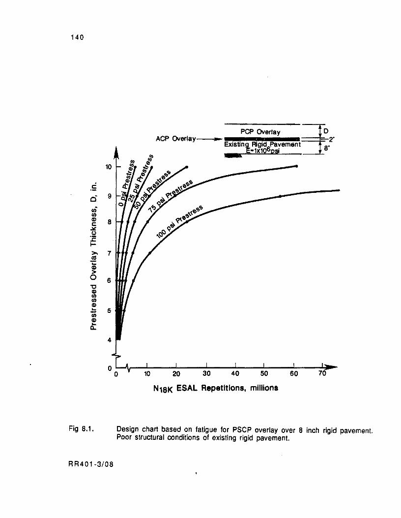
140
. . 5 ci .. en en <D c:
::tt! ()
:E I-
>-.! ... <D > 0 "tJ <D en en <D ... -en <D ... Il..
Fig 8.1.
PCP Overlay ~ ACP Overlay'---tl .... - 2'
Existin~ Rlgig:Pa~ement. 8-.5·1X1~pSl
10
9
8
7
6
5
o ~~r-~----~----~----~--~----~--~~~ o N18K ESAL Repetitions, millions
Design chart based on fatigue for PSCP overlay over 8 inch rigid pavement. Poor structural conditions of existing rigid pavement.
R R401-3/08
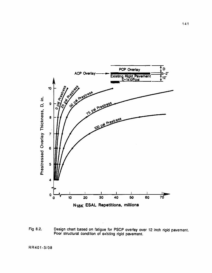
10
. . ~ ci 9 .
(I) (I) Q) 8 c:
.:JJ:. (J
.r::. I->- 7 a:I i: (I)
> 0 6 "0 Q) (I) (I) Q) ... 5 -(I)
CD ... 0..
4
Fig B.2.
RR401-3/0B
141
PCP Overlay ~ ACP Overlay---II ........ Existing Rigid Pavem.nt 12~·
E-1x1Q6ps!
20
N18K ESAL Repetitions. millions
Design chart based on fatigue for PSCP overlay over 12 inch rigid pavement. Poor structural condition of existing rigid pavement.
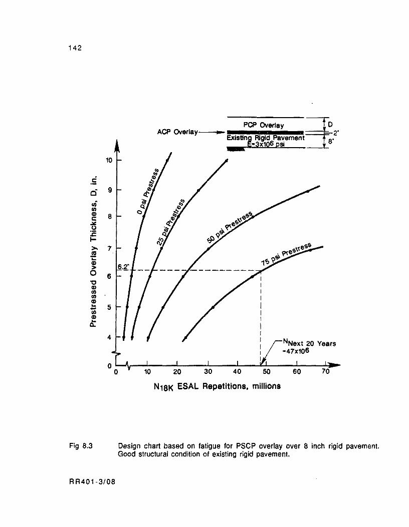
142
.5
rh U) CD c: ~ u :E I->.! "-CD > o '0 CD U) U)
CD .... -U) CD
Q:
Fig 8.3
10
9
8
7
6
5
4
RR401-3/08
6.2·
PCP Overlay ~ ACP Overlay-__._- 2· Existing Rigid Pa~ement 8.
§-3x10⁶ pSI
N18K ESAL Repetitions, millions
NNext 20 Years -47x106
Design chart based on fatigue for PSCP overlay over 8 inch rigid pavement. Good structural condition of existing rigid pavement.
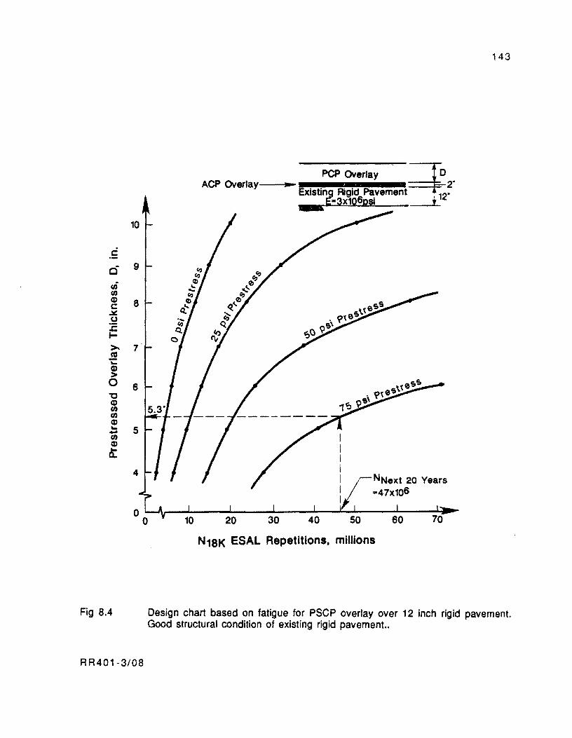
c .-0 ur (1.1 Q) c: ~ u :c I-
>-co 'i: Q) > 0 "C Q) (1.1 til Q) .. -(1.1 Q) .. a..
Fig 8.4
143
PCP Overlay ~ ACP Overlay'----il .. - 2"
ExistinJJ Rigid Pavement I 12" ~-3X10⁶psi ,
10
9 0,0,
.... 0 r;-
8 .... 0 \t
eSS ~ " . ~teS Q.~
9S\
<t' -roO 7
6
5
4 NNext 20 Years -47x106
o ~~---~--~~--~~--~--~~----~----~~ o N18K ESAL Repetitions, millions
Design chart based on fatigue for PSCP overlay over 12 inch rigid pavement. Good structural condition of existing rigid pavement..
R R401-3/08
144
having an elastic modulus of 3 million psi. Most rigid pavements should exhibit elastic moduli
within this range by the time a major rehabilitation is needed. Methods for evaluating the
elastic properties of in-service rigid pavements, prior to overlaying, are discussed in Ref 4.
The solutions in Figs 8.1 to 8.4 assume that a 2-inch ACP layer is provided between the old
pavement and the prestressed overlay. The use of this layer is essential to patch and seal the
old pavement, provide a uniform support for the overlay, and avoid the risk that cracking of
the old pavement may propagate to the PCP. Full slip at the interface between the PCP and the
ACP was assumed in the development of these charts for this is the effect produced by the
introduction of friction relieving interlayers at the interface. These charts cover the
thickness range of most existing Texas pavements. Overlays in design conditions intermediate
to those considered by Figs 8.1 to 8.4 can be designed by interpolation between the results of
designs from these charts.
The procedure followed to develop the design charts in Figs 8.1 to 8.4 is presented in
great detail in Ref 4. It consisted of the application of multi-layered elastic theory to
determine the stress levels produced by a standard 18-kip ESAL at the bottom of overlays of
different thicknesses. Then, the stress levels thus obtained were reduced by imposing
different slab prestress levels. These reduced stresses were subsequently input into a fatigue
relationship for jointed pavements to obtain the curves in each figure.
Step 2. Assume an initial slab length which,in the designer's judgement, may result in
final joint openings of less than 4 inches for the overlay site environmental conditions.
Lengths commonly used vary between 200 and 500 ft. The chart in Fig 8.5 may be used to get
an initial estimate of this parameter. This chart was used in the selection of the slab lengths
of the McLennan County overlay. It was developed from slab end movements recorded in the
Virginia, Arizona and Mississippi Projects (Refs 8, 10, and 11). The development of this
chart is documented by Mendoza, McCullough, and Burns in Ref 4.
In a subsequent step in this procedure, the length assumed in this step will be checked
with the more accurate predictions from computer program PSCP1.
Step 3. As mentioned in Chapter 2, the tensile stress at the bottom of the pavement due
to traffic loads is an input to the elastic design of PCP slabs. To estimate this stress. Figs 8.6,
8.7, 8.8 and 8.9 can be used. These figures were obtained by running BISAR (Ref 55) on the
model presented at the top of each figure. BISAR was selected for developing these charts
because it allows for specifying a variable amount of slip at the interface between the PCP and
the ACP. Full slip at the interface was assumed in these charts to include the effect of using
R R401-3/08
:0 :0 ~ o ...... , CtJ
--o Q)
. c
.. CJ) c .-C tD C-O ... c '0 .., as ... o I-
Maximum Allowable 41. _________________________ _
3 2.3 in.
2 Slab Length = 240ft
1
o IC .n
o 100 200 250 300 350 400 450 500
Slab Length, ft
Fig 8.5. Expected jOint opening versus slab length from slab end movements recorded in the Virginia. Arizona, and Mississippi projects (Refs 8, 10, and 11). ~
01
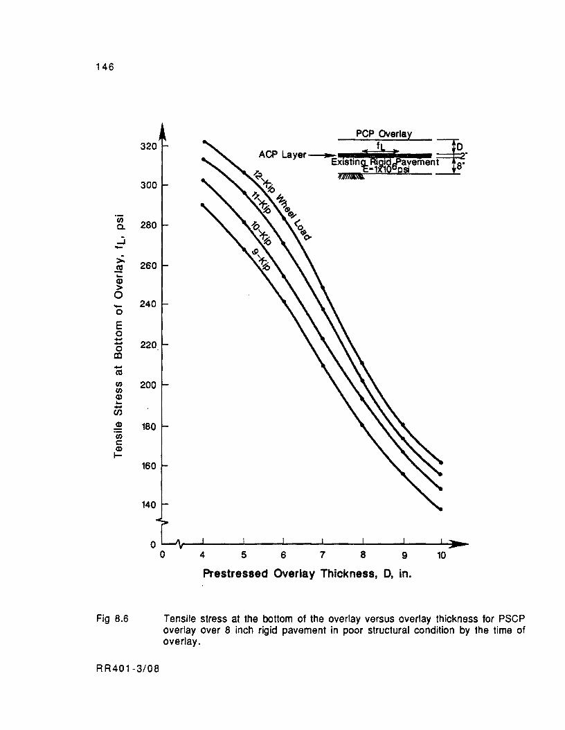
146
320
300
rn 280 c.
..,.j ->- 260 .!!! "-CD > 0 - 240 0
E 0 .... .... 220 0
CO .... as rn 200 rn CD "-....
(f)
.! 180 rn c: CD I-
160
140
o
Fig 8.6
R R40 1-3/08
o 4 5 6 7 8 9 10
Prestressed Overlay Thickness, D, in.
Tensile stress at the bottom of the overlay versus overlay thickness for PSCP overlay over 8 inch rigid pavement in poor structural condition by the time of overlay.
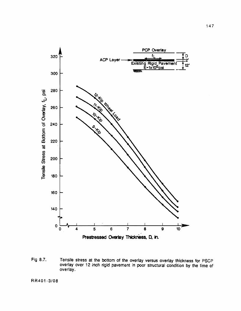
320
300
"Cij 280 Co ..,:, ->. 260 ~
~ - 240 0
E 0 -S 220
lU (/J (/J
! 200 en ~ "Cij r.: ~ 180
160
140
Fig 8.7.
RR401-3/08
147
PCP ~erlay 3D
ACP Layer__._ • t 2" Existing Rigid Pavement 12"
E-1x10~psi
Prestressed Overlay Thic:k1iess, D, in.
Tensile stress at the bottom of the overlay versus overlay thickness for PSCP overlay over 12 inch rigid pavement in poor structural condition by the time of overlay.
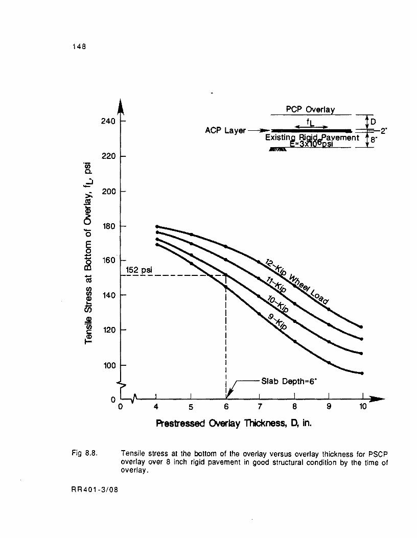
148
240
220 'c;; 0-
..:. ->. 200 ~
! 180 -0
E 0 -~ 160
ca f/) f/) 140 Q) .... 05 .m 'c;; 120
~
100
Fig 8.8,
RR401-3/08
4 5
R'estressed CNerlay Thickness, 0, in.
Tensile stress at the bottom of the overlay versus overlay thickness for PSCP overlay over 8 inch rigid pavement in good structural condition by the time of overlay,
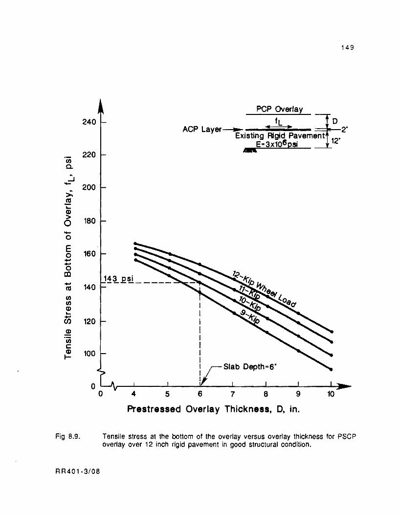
240
220 (/)
a. .. ...J - 200 .. >-~ ~
Q) > 180 0 -0
E 160 0 --0 to - 140 a:s (/) (/) Q) ~ -(/) 120 Q) .-(/) c: Q) 100 t-
Fig 8.9.
RR401-3/08
149
pcp Overlay
ACP Layer .. ..)II 2" fL ~ Existing Rigid Pavement 12"
E=3x10⁶Qsi --
5 7 8
Prestressed Overlay Thickness, 0, in.
Tensile stress at the bottom of the overlay versus overlay thickness for PSCP overlay over 12 inch rigid pavement in good structural condition.

150
friction relieving materials at the interface. Interpolation can. be used in design for conditions
intermediate to those considered by these charts. For conditions outside the range of these
charts, the wheel load stresses can be calculated using one of the computer codes to predict
stresses from multilayered elastic theory (Refs 29 and 55), preferably BISAR (Ref 55), or
any of the finite element computer programs (Ref 30).
Step 4. In this step, the allowable flexural stress, which is another input variable of
the elastic design procedure for PCP slabs, should be determined from the concrete flexural
strength information. First, the 28-day concrete flexural strength should be estimated. An
estimate of this parameter can be obtained from numerous flexural tests on beams using third
point loading, according to ASTM C78 (Ref 26). The tests should be performed on trial
batches of concrete using the aggregate and cement for mix designs expected to be used in the
project.
The allowable flexural stress can be determined by dividing the 28-day flexural
strength by a safety factor. ACI Committee 325 (Ref 1) suggests the use of values between 1.5
and 2.0 as safety factors for secondary and primary highways, respectively.
Step 5. For the problem considered, complete the set of design inputs for computer
program PSCP1, as described in Chapter 6, in the section on the description of the program
input data.
A sequence of post-tensioning forces applied at certain hours after curing should be
assumed initially for the initial period. Whether these forces can avoid the formation of
premature cracks in the slab or whether they can be withstood by the concrete without causing
anchor zone failure is the design aspect covered in stage 2 of this methodology. Temporary
estimates of these parameters should be defined in this step and checked later in stage 2.
Step 6. Determine the strand spacing for which the elastic design criterion is met (Eq
2.1 in Chapter 2). The elastic design equation should be established for the stresses
developing at the bottom of the slab at midlength on a summer day near the end of the overlay
design Hfe. The detrimental effect of all factors considered in this study is additive for this
condition. A summer day should be analyzed because the largest environmental stresses (due
to friction and curling) develop during summer days as the fluctuations of air temperatures
are generally the largest of the year. Likewise, a day near the end of the overlay design life
should be considered because it is when the prestress level is minimum, as almost al\
prestress losses have occurred.
RR401-3/08
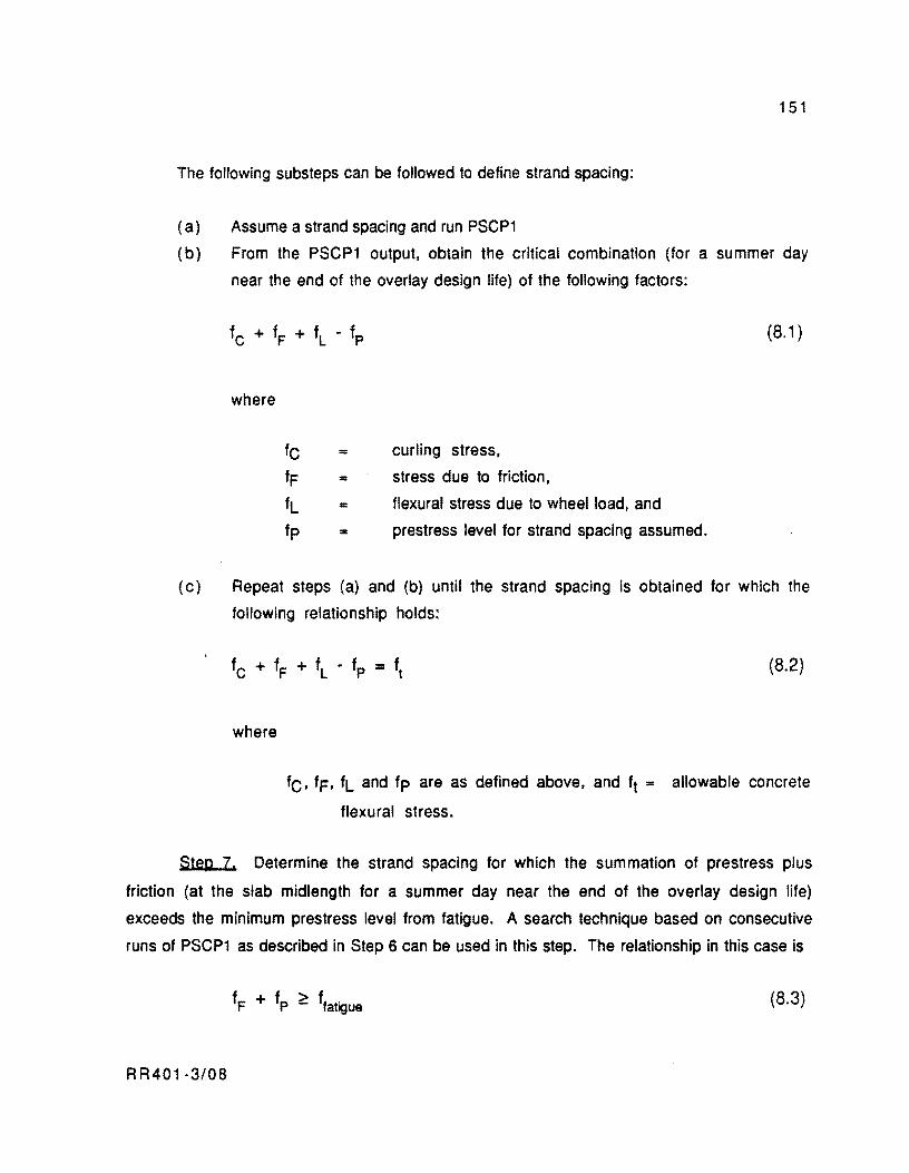
151
The following substeps can be followed to define strand spacing:
( a) Assume a strand spacing and run PSCP1
(b) From the PSCP1 output. obtain the critical combination (for a summer day
near the end of the overlay design life) of the following factors:
(8.1 )
where
fC = curling stress,
fF = stress due to friction.
fL - flexural stress due to wheel load, and
fp ... prestress level for strand spacing assumed.
(c) Repeat steps (a) and (b) until the strand spacing is obtained for which the
following relationship holds:
where
(8.2)
fC, fF' fL and fp are as defined above, and ft = allowable concrete
flexural stress.
Step 7. Determine the strand spacing for which the summation of prestress plus
friction (at the slab midlength for a summer day near the end of the overlay design life)
exceeds the minimum prestress level from fatigue. A search technique based on consecutive
runs of PSCP1 as described in Step 6 can be used in this step. The relationship in this case is
(8.3)
RR401·3/0B
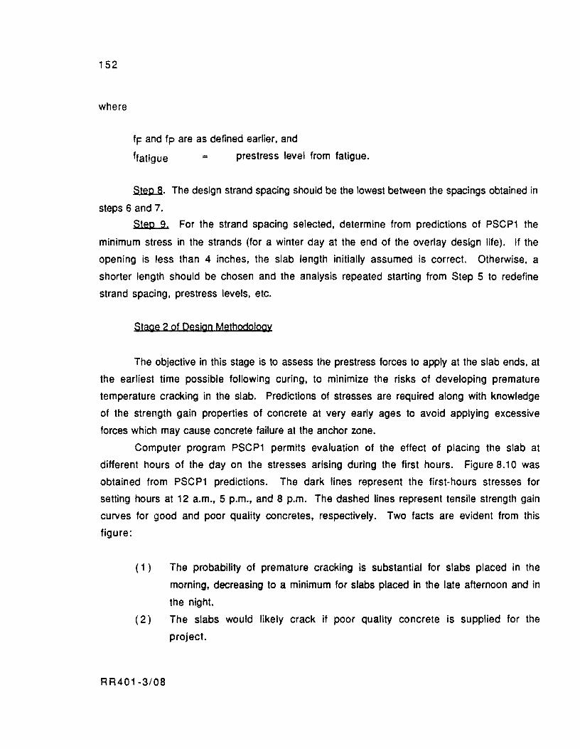
152
where
fF and fp are as defined earlier, and
ffatigue = prestress level from fatigue.
Step 8. The design strand spacing should be the lowest between the spacings obtained in
steps 6 and 7.
Step 9. For the strand spacing selected, determine from predictions of PSCP1 the
minimum stress in the strands (for a winter day at the end of the overlay design life). If the
opening is less than 4 inches, the slab length initially assumed is correct. Otherwise. a
shorter length should be chosen and the analysis repeated starting from Step 5 to redefine
strand spacing, prestress levels, etc.
Stage 2 of Design Methodology
The objective in this stage is to assess the prestress forces to apply at the slab ends, at
the earliest time possible following curing, to minimize the risks of developing premature
temperature cracking in the slab. Predictions of stresses are required along with knowledge
of the strength gain properties of concrete at very early ages to avoid applying excessive
forces which may cause concrete failure at the anchor zone.
Computer program PSCP1 permits evaluation of the effect of placing the slab at
different hours of the day on the stresses ariSing during the first hours. Figure 8.10 was
obtained from PSCP1 predictions. The dark lines represent the first-hours stresses for
setting hours at 12 a.m., 5 p.m., and 8 p.m. The dashed lines represent tensile strength gain
curves for good and poor quality concretes, respectively. Two facts are evident from this
figure:
( 1 ) The probability of premature cracking is substantial for slabs placed in the
morning. decreasing to a minimum for slabs placed in the late afternoon and in
the night.
( 2) The slabs would likely crack if poor quality concrete is supplied for the
project.
RR401-3/08

153
In this study, it will be considered that the total prestress will be completed in two
stages (initial and final). Likewise, it will be considered that, independently of the setting
hour, all slabs will be post-tensioned initially as soon as they get enough strength to withstand
10 kips at the anchor zone. To apply a force in the neighborhood of 10 kips at the initial stage
has been common of previous US prestress projects (Ref 4). The aspects to define herein are
then
( 1 ) Time of application of initial prestress,
(2) Whether or not 10 kips of initial prestress is sufficient to avoid temperature
cracking in the slab, and
( 3 ) Time of application of final prestress.
The following steps can be used to define these aspects.
Step 1. Determine from Fig 8.11 the compressive strength required in the concrete
that allows a 10-kip load at the anchor. This figure was determined from tests reported by
O'Brien, Burns, and McCullough (Ref 22) on the capacity of the anchorage zone for very early
post-tensioning. Given its empirical nature, the use of this chart is limited to applications
similar to those of the study conducted by O'Brien, et at
( 1 ) Concrete compressive strengths between 0 and 2000 psi,
( 2 ) Slab thicknesses of 6 to 8 inches,
( 3 ) Strand spacings of 12 and 24 inches,
( 4 ) 0.6-inch-diameter mono-strand flat anchors with 16.19 and 21 square inches
in area.
Interpolation or extrapolation for conditions different than these is possible, but the
designer should be careful to be sure that the tests verify adequate safety.
Step 2. Determine the compressive strength versus age relationship of concrete at
very early ages. This relationship can be derived from compressive strength tests performed
on cylindrical specimens at different ages according to ASTM C 39 or AASHTO T22, T140 test
specifications (Refs 26 and 56). As for the flexural strength, the compressive strength
should be evaluated by performing the tests on small trial batches of concrete using the
aggregate and cement for mix designs anticipated to be used in the project.
RR401-3/08
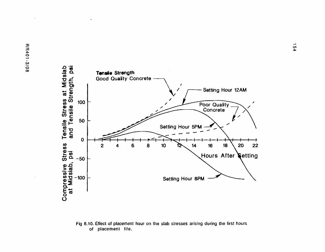
::IJ ::IJ ~ o .....
I
(..) ....... o (X)
.0 .•
.!9a. rn _ "OJ::. .--::::Eo
c: -cu as .... -Strength
T.,..I11_ Hty Concrete \ ' Good Qua ~I
r--_ Setting Hour 12AM
/ rn(J) rn cu..!!
100 Poor Quality --......... / - Concrete 7 ... ") / ..... --rn (J)c:
G)G) =1-rn"O C:c: ~as rn rn G)..... rn
50
o
,.
2 4 6 8
Cii a. -50 After -G).o
>as ·iii "iii rn "0 -100 cu·- Setting Hour 8PM .... ::::E a. eoas o
Fig 8.10. Effect of placement hour on the slab stresses arising during the first hours of placement life.
22
...... <.n ~
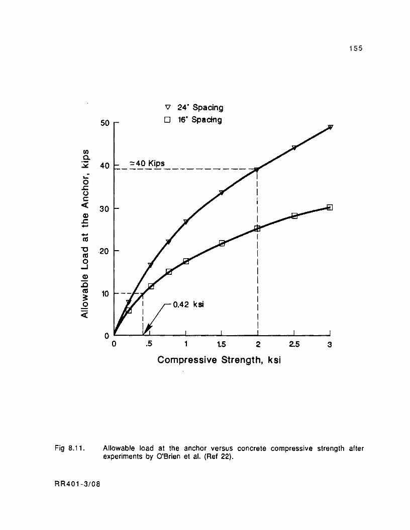
tJ)
a.
50
.::i:. 40 ~ ....
o .c: (J c:: « CD .c: ..... ..... ca
30
"020 ca o ...J CD .a ca ~ o «
10
" 24- Spacing o 16- Spacing
o ~--~~----~------~----~----~~--~ o .5 1 1.5 2 2.5 3
Compressive Strength, ksi
155
Fig 8.11. Allowable load at the anchor versus concrete compressive strength after experiments by O'Brien et al. (Ref 22).
RR401-3/08
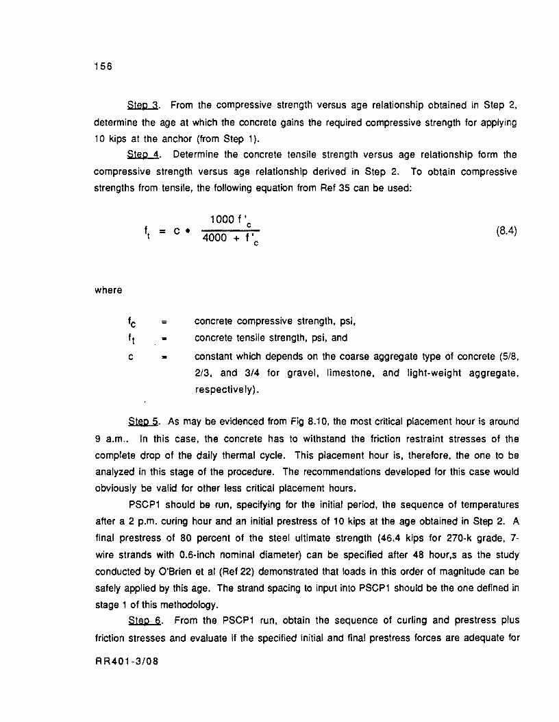
156
Step 3. From the compressive strength versus age relationship obtained in Step 2,
determine the age at which the concrete gains the required compressive strength for applying
10 kips at the anchor (from Step 1).
Step 4. Determine the concrete tensile strength versus age relationship form the
compressive strength versus age relationship derived in Step 2. To obtain compressive
strengths from tensile, the following equation from Ref 35 can be used:
where
fc = f t = c =
1000 f IC
4000 + f'c
concrete compressive strength, psi,
concrete tensile strength, pSi, and
(804)
constant which depends on the coarse aggregate type of concrete (5/8,
213. and 3/4 for gravel, limestone. and light-weight aggregate.
respectively) .
Step 5. As may be evidenced from Fig 8.10, the most critical placement hour is around
9 a.m.. In this case, the concrete has to withstand the friction restraint stresses of the
complete drop of the daily thermal cycle. This placement hour is, therefore, the one to be
analyzed in this stage of the procedure. The recommendations developed for this case would
obviously be valid for other less critical placement hours.
PSCP1 should be run, specifying for the initial period, the sequence of temperatures
after a 2 p.m. curing hour and an initial prestress of 10 kips at the age obtained in Step 2. A
final prestress of 80 percent of the steel ultimate strength (46.4 kips for 270-k grade, 7-
wire strands with 0.6·inch nominal diameter) can be specified after 48 hour,s as the study
conducted by O'Brien et al (Ref 22) demonstrated that loads in this order of magnitude can be
safely applied by this age. The strand spacing to input into PSCP1 should be the one defined in
stage 1 of this methodology.
Step 6. From the PSCP1 run, obtain the sequence of curling and prestress plus
friction stresses and evaluate if the specified initial and final prestress forces are adequate for
RR401·3/08
157
eliminating the chances of developing premature cracking. If not, the 10-kip initial
prestress may be increased and the procedure repeated starting from Step 3 of this stage.
EXAMPLE PROBLEM
An example design problem using the concepts and procedures presented in this chapter
is shown in this section.
Stage 1 of Desjgn Methodology
Step 1. Design a PCP overlay to be placed in a two-lane rural interstate highway. The
existing pavement is a 10-inch CRCP 38-feet wide. The design traffic to be carried by the
facility for a design life of 20 years is 52 x 106 18-kip ESAL. The total traffic in the design
lane can be obtained by modifying the design traffic of the two-lane facility with a lane
distribution factor of 0.9 as recommended by Elkins and McCullough (Ref 52) for CRCP
design. Namely,
N18-k ESAL = 52 x 106
x 0.9 = 47 x 106
A design elastic modulus for the existing pavement was back-calculated from a set of
deflection basins measured with the Dynaflect. (For details on this evaluation procedure. the
reader should consult Ref 4). A concrete elastic modulus of 3 x 10⁶ psi was obtained from
this evaluation.
Interpolating between the thickness values in Figs 8.3 and 8.4 for a 75-psi prestress
level:
Existing Pavement Thickness, Inches
8 10 12
6.2 5.8 5.3
RR401·3/08
158
Therefore, a slab thickness of 6 inches and a midslab prestress level of 75 psi are
initially assumed.
Step 2. Selecting a length of PCP slabs between expansion joints of 240-feet, an
expected total joint opening of 2.3 inches is read from Fig 8.5. This opening is lower than the
4-inch maximum allowed.
Step 3. The elastic design of the slabs is to be performed for the maximum 20-kip
single axle load allowed in interstate highways. The axle consists of two 10-kip loads spaced
72 inches from center to center of loads. The tensile stress at the bottom of the overlay can be
obtained by interpolation between the stress values from Figs 8.8 and 8.9:
Existing Pavement Thickness, Inches
8 10 12
152 148 143
Therefore, a wheel load stress fL = 148 psi is obtained.
Step 4. A 28-day flexural strength of 730 psi was obtained from flexural tests on
beams. For the rural facility with high traffic considered, a safety factor of 2.00 is assumed.
Correspondingly, the allowable concrete flexural stress is
ft = 730/2.00 = 365 psi
Step 5. The information presented in Table 8.1 is available for the problem
considered. The friction coefficient versus displacement curve assumed herein correspond to a
single polyethylene film. A slab placed early in the morning of a summer day and cured at
2:00 p.m .• approximately at the maximum temperature of the day. is to be analyzed. The
curing temperature is 90°F. If prestress forces are required, the strands should be stressed
initially to a stress of 46.2 psi {10 kips per strand}. The codification of these data. to input
into PSCP1, is given in the first part of Appendix C.
Step 6. The stresses obtained from PSCP1 for summer and winter days near the end of
the pavement design life (20 years = 7300 days) are given in Table 8.2. The stresses at
R R401-3/08
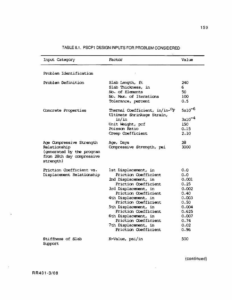
TABLE 8.1. PSCP1 DESIGN INPUTS FOR PROBLEM CONSIDERED
Input category
Problem Identification
Problem Definition
Cbncrete Properties
Age Canpressi ve Strength Relationship (generatEd by the program f~ 28th day oampressive strength)
Friction Coefficient vs. Displacement Relationship
Stiffness of Slab Supp:::>rt
RR401-3/08
Factor
Slab Umgth, ft Slab 'Ihickness, in No. of Elements No. Max. of Iterations 'Iblerance, percent
Thermal Coefficient, in/in-or Ultimate Shrinkage Strain,
in/in Unit 'height, pef FbisSCJ1. Ratio Creep Coefficient
Age, Days Canpressi ve Strength, 'psi
1st Displacement, in Friction Coefficient
2nd Displacement, in Friction Coefficient
3rd Displacement, in Friction Coefficient
4th Displacement, in Friction Coefficient
5th Displacement, in Friction Coefficient
6th Displacement, in Friction Coefficient
7th Displacement, in Friction Coefficient
K-Value, psi/in
Value
240 6 50 100 0.5
5xlO-6
3xlO-4
150 0.15 2.10
28 3000
0.0 0.0 0.001 0.25 0.002 0.40 0.003 0.50 0.004 0.625 0.007 0.74 0.02 0.96
500
159
( continued)
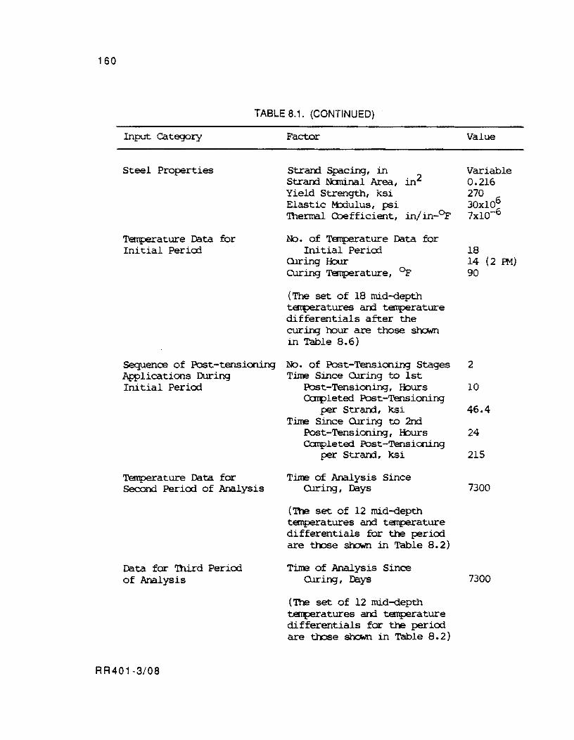
160
TABLE 8.1. (CONTINUED)
Input category
Steel Pro:perties
Temperature D.::ita for Initial Peric:rl
Sequence of Post-tensioning Applications During Initial Period
Temperature D.::ita for Second Period of Analysis
D.::ita for nrlrd Period of Analysis
RR401-3/08
Factor
Strarrl Spacing, in Strarrl. N:::m.inal Area, Yield Strength, ksi Elastic M:xiulus, psi Thermal COefficient,
. 2 ill
in/in-O:F
No. of Temperature D.::ita for Initial Peric:rl
QJring !:bur curing TEmperature, O:F
(The set of 18 mid-depth temperatures and temperature differentials after the cur ing hour are those sh.<::x-m in Table 8.6)
No. of Post-Tensioning Stages Time Since OJring to 1st
Post-Tensioning, Iburs Conpleted Post-Tensioning
per Strarrl., ksi Time Since QJring to 2nd
Post-Tensioning, Iburs Cc:nplete::i Post-Tensioning
per Strarrl., ksi
Time of Analysis Since OJring, D.::iys
('Ibe set of 12 mid-depth temperatures and temperature differentials for the period are t:l'n3e sb:::1N.n in Table 8. 2)
Time of Analysis Since OJring, Days
('Ibe set of 12 mid-depth temperatures arrl temperature differentials for the period are t:l'n3e shown in Table 8.2)
Value
Variable 0.216 270 30Xl06
6 7xl0-
18 14 (2 R1) 90
2
10
46.4
24
215
7300
7300
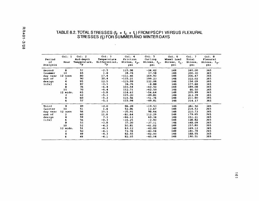
::D ::D TABLE 8.2. TOTAL STRESSES (l + fc + ~) FROM PSCP1 VERSUS FLEXURAL .Iloo 0 STRESSES (ft ) FOR UMMER ND WINTER DAYS ...... . Ul -0 OJ
Col. 1 Col. 2 Col. 3 Col. 4 Col. 5 Col. 6 Col. 7 Col. 8 Period Hid-depth Temperature Friction Curling Wheel Load Total Flexural
of Hour Temperature, Differential, Stres8~ f F , Stress~ f C ' Stress~ f L, Stress, Stress. fT' Analysis of of PSl PSl PSl psi psi
Second 8 57 -2.5 115.98 -24.42 148 240.00 365 (summer 10 65 1.8 34.76 17.58 148 200.30 365 day near 12 noon 80 17.4 -111.46 169.93 148 206.47 365 end of 2 90 20.4 -115.21 199.23 148 232.02 365 design 4 95 12.5 -115.99 122.08 148 154.09 365 1 ife) 6 87 -0.5 34.76 -4.88 148 177 .88 365
8 78 -6.4 103.54 -62.50 148 189.08 365 10 70 -6.4 112.71 -62.50 148 85.50 365
12 midn. 65 -5.8 114.63 -54.64 148 205.99 365 2 62 -5.1 115.20 -49.81 148 213.39 365 4 60 -5.3 115.56 -51.76 148 211.80 365 6 57 -5.1 115.98 -49.81 148 214.17 365
Third 8 49 -2.0 86.28 -19.53 148 281.50 365 (winter 10 51 1.4 52.86 13.67 148 214.53 365 day near 12 noon 56 10.1 -35.91 98.64 148 210.73 365 end of 2 60 11.6 -81.64 113.29 148 179.65 365 design 4 59 7.1 -66.13 69.34 148 151.21 365 life) 6 56 -0.3 -16.25 -2.93 148 128.82 365
8 53 -3.8 37.20 -37.11 148 148.09 365 10 52 -4.2 50.81 -41.02 148 157.80 365
12 midn. 51 -4.3 63.12 -42.00 148 169.12 365 2 50 -4.1 73.78 -40.04 148 181.74 365 4 49 -4.3 82.55 -42.00 148 188.55 365 6 49 -4.1 82.55 -40.04 148 190.51 365
0'>
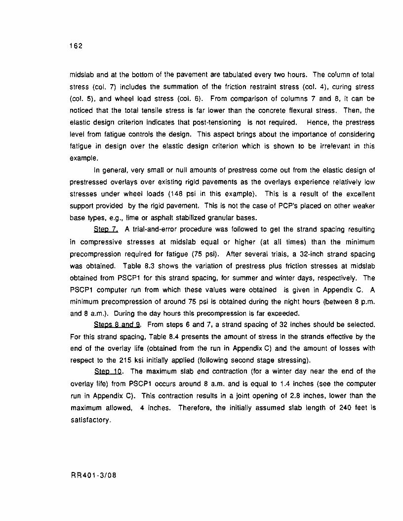
162
midslab and at the bottom of the pavement are tabulated every two hours. The column of total
stress (col. 7) includes the summation of the friction restraint stress (col. 4), curing stress
(col. 5), and wheel load stress (col. 6). From comparison of columns 7 and 8, it can be
noticed that the total tensile stress is far lower than the concrete flexural stress. Then, the
elastic design criterion indicates that post-tensioning is not required. Hence, the prestress
level from fatigue controls the design. This aspect brings about the importance of considering
fatigue in design over the elastic design criterion which is shown to be irrelevant in this
example.
In general, very small or null amounts of prestress come out from the elastic design of
prestressed overlays over existing rigid pavements as the overlays experience relatively low
stresses under wheel loads (148 psi in this example). This is a result of the excellent
support provided by the rigid pavement. This is not the case of PCP's placed on other weaker
base types, e.g., lime or asphalt stabilized granular bases.
Step 7. A trial-and-error procedure was followed to get the strand spaCing resulting
in compressive stresses at midslab equal or higher (at all times) than the minimum
precompression required for fatigue (75 psi). After several trials, a 32-inch strand spacing
was obtained. Table 8.3 shows the variation of prestress plus friction stresses at midslab
obtained from PSCP1 for this strand spacing, for summer and winter days, respectively. The
PSCP1 computer run from which these values were obtained is given in Appendix C. A
minimum precompression of around 75 psi is obtained during the night hours (between 8 p.m.
and 8 a.m.). During the day hours this precompression is far exceeded.
Steps 8 and 9. From steps 6 and 7, a strand spacing of 32 inches should be selected.
For this strand spacing, Table 8.4 presents the amount of stress in the strands effective by the
end of the overlay life (obtained from the run in Appendix C) and the amount of losses with
respect to the 215 ksi initially applied (following second stage stressing).
Step 10. The maximum slab end contraction (for a winter day near the end of the
overlay life) from PSCP1 occurs around 8 a.m. and is equal to 1.4 inches (see the computer
run in Appendix C). This contraction results in a joint opening of 2.8 inches, lower than the
maximum allowed, 4 inches. Therefore, the initially assumed slab length of 240 feet is
satisfactory.
RR401·3/08
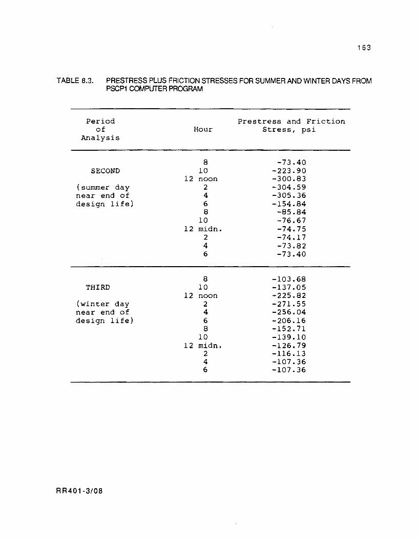
163
TABLE 8.3. PRESTRESS PLUS FRICTION STRESSES FOR SUMMER AND WINTER DAYS FROM PSCP1COMPUTERPROGRAM
Period Prestress and Friction of Hour Stress, psi
Analysis
8 -73.40 SECOND 10 -223.90
12 noon -300.83 (summer day 2 -304.59 near end of 4 -305.36 design life) 6 -154.84
8 -85.84 10 -76.67
12 midn. -74.75 2 -74.17 4 -73.82 6 -73.40
8 -103.68 THIRD 10 -137.05
12 noon -225.82 (winter day 2 -271.55 near end of 4 -256.04 design life) 6 -206.16
8 -152.71 10 -139.10
12 midn. -126.79 2 -116.13 4 -107.36 6 -107.36
RR401-3/08
164
TABLE 8.4. FINAL STRESS IN STRANDS FROM COMPUTER PROGRAM PSCP1 AND COMPUTATION OF PERCENT LOSSES WITH RESPECT TO INITIAL STRAND STRESS
Period Stress in Loss With Percent of Strands, Respect to Losses
Analysis ksi Initial 215 Ksi, ( % ) Ksi
SECOND (summer day 168.3 46.7 21.7 near end of design life)
THIRD (winter day 168.8 46.2 21.4 near end of design life)
R R40 1-3/08
165
Stage 2 of Design Methodology
Step 1. From Fig 8.11, a 420-psi compressive strength is required for an allowable
load at the anchor of 10 kips.
Step 2. The concrete compressive strength versus age relationship in Table 8.5 is
available for design.
Step 3. The age at which concrete gains a 420-psi compressive strength can be
obtained interpolating between the ages for 300 psi and 580 psi in Table 8.5. The concrete
gains 420 psi after approximately 10 hours.
Step 4. The tensile strength values corresponding to the compressive strength versus
age relationship from Step 2 are reported in Table 8.5.
Steps 5 and 6. Table 8.6 shows the sequence of prestress plus friction and curling
stresses, at midslab, obtained from PSCP1 for a setting hour at 2:00 p.m., specifying 10 kips
after 10 hours and 46.4 kips after 24 hours since slab setting. These values were obtained
for the initial period of the PSCP1 computer run included in Appendix C. A total of 46.4 kips
was specified after 24 hours because, from Table 8.5, the concrete gains 2000 psi after 24
hours. For this strength, Fig 8.11 indicates that almost 40 kips can be allowed at the anchor
for a 24-inch strand spacing. It is considered, then, that the concrete can withstand safely
46.4 kips for the 32-inch strand spacing defined in stage 1 of this example. The column of
total stress in Table 8.6 corresponds to the sum of the columns of prestress plus friction
stresses and the column of curling stresses.
From a comparison of the columns of total stress and tensile strength in Table 8.6, it is
apparent the high chance of cracking is during the first 10 hours since curing. However,
after applying the initial prestress (12:00 midnight). the tensile strength decreases far
below the tensile strength. The tensile strength, on the other hand, keeps on increasing until
the concrete attains strength levels at which cracking occurrence may be fairly unlikely.
An alternative that may reduce the chance of cracking during the first 10 hours would
be to reduce the initial post-tensioning development force below 10 kips and apply it sooner.
However, 10 kips is considered as a reasonable minimum that is desirable for a prestressing
stage, given the labor time and cost involved in post-tensioning operations (Ref 4).
Therefore, 10 kips at the slab ends after 10 hours and 46.4 after 24 hours is a viable post
tensioning strategy.
R R401-3/08
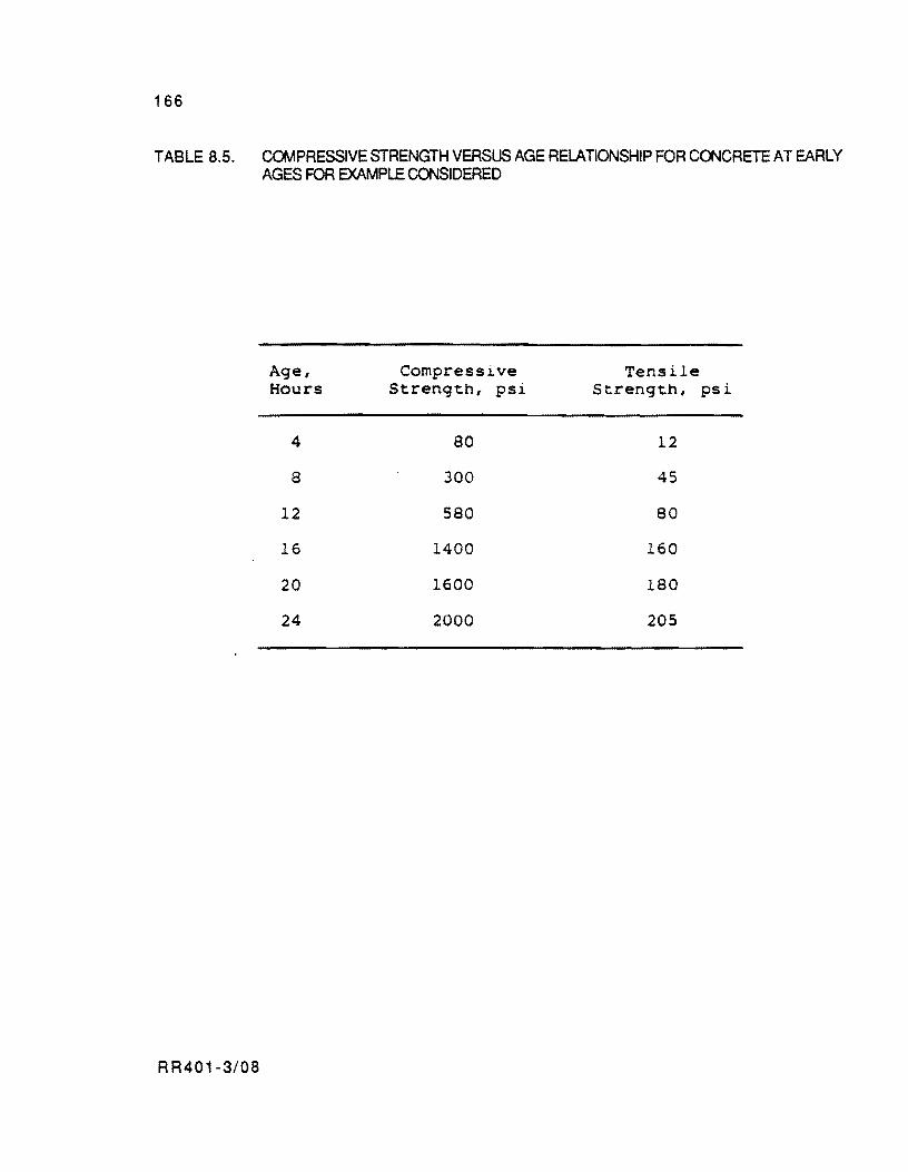
166
TABLE 8.5. COMPRESSIVE STRENGTH VERSUS AGE RELATIONSHIP FOR COOCRETE AT EARLY AGES FOR EXAMPLE COOSIDERED
Age, Compressive Tensile Hours Strength, psi Strength, psi
4 80 12
8 300 45
12 580 80
16 1400 160
20 1600 180
24 2000 205
RR401-3/08
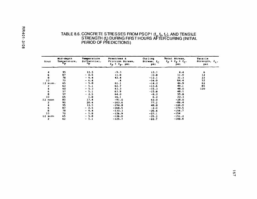
:0 :0 -1:00 o ..... . t.) -. o <XI
Hour
4 6 8
10 12 mldn.
2 4 6 8
10 12 noon
2 4 6 8
10 12 midn
2
TABLE 8.6. CONCRETE STRESSES FROM PSCP1 (f~e fd. AND TENSILE STRENGTH (fJ DURING FIRST HOURS At-I ER CURING (INITIAL PERIOD OF PHEDICTIONS)
Mid-depth ,. ..... r.ture Pr •• tr... " CurlinCj Tot.l Str ••• , T.nsil. Temgerature, Diff.rntial, Friction Stre.e. Str ••• , . fC fp + fF + fc' Strength,
I" OF fp + fF' pei pel. pal. pai
95 12.5 -9.3 13.7 4.4 6 87 - 0.5 U.8 -0.8 11.0 12 78 - 6.4 43.4 -12.1 31.3 23 70 - 6.4 .4 -14.0 64.4 52 65 - 5.8 61.1 -14.2 46.9 63 62 - 5.1 62.7 -13.6 49.1 85 60 - 5.3 63.3 -15.3 48.0 120 57 - 5.1 63.9 -15.8 48.1 57 - 2.5 64.0 -8.2 55.8 65 1.8 16.1 6.2 22.3 80 17.4 -91.0 63.0 -28.0 90 20.4 -163.6 77.2 -86.4 95 12.5 -194.8 48.8 -146.0 87 - 0.5 -168.5 -2.0 -170.5 78 - 6.4 -130.3 -26.4 -156.7 70 - 5.8 -126.9 -27.1 -154 65 - 5.8 -126.0 -25.2 -151.2 62 - 5.1 -125.7 -22.7 -148.4
ft,
..... CD ".J

!!!!!!!!!!!!!!!!!!!"#$%!&'()!*)&+',)%!'-!$-.)-.$/-'++0!1+'-2!&'()!$-!.#)!/*$($-'+3!
44!5"6!7$1*'*0!8$($.$9'.$/-!")':!
CHAPTER 9. SUMMARY, CONCLUSIONS AND RECOMMENDATIONS
This chapter presents a summary of findings and conclusions resulting from this study
of modeling the behavior of PCP slabs to incorporate the model into a design procedure. As the
results presented herein are based on a small sample of data, they must not be considered as
universal, but indicative of the expected behavior that must be checked for each project until
enough data becomes available to verify the model. Recommendations for further research are
also provided as possible extensions of the design methodology presented.
SUMMARY AND CONCLUSIONS
In Chapter 2, a detailed description of the important variables affecting PCP behavior
and the design factors covered in this study are presented. These are the relevant statements
in this chapter:
( 1 ) The movements of PCP slabs can be classified as short-term and long-term
movements. Short-term movements, i.e., those due to daily temperature
changes occur restrained by the friction. Therefore, slab stresses due to
friction develop almost exclusively as a result of these movements. Long-term
movements, i.e., those produced by concrete swelling, shrinkage, creep, and
seasonal temperature changes, occur unrestrained by the friction. Therefore,
concrete stresses due to friction are not caused by these movements. However,
since their magnitude is fairly significant in the long term, the variations of
the prestress level are primarily a result of the accumulation of these
movements.
Slab elastic shortening due to prestress forces occurs under frictional
resistance when the prestress forces are applied. However, the effect of the
friction dissipates shortly after prestressing. These movements can be
considered, therefore, as temporarily restrained by the friction.
(2) An elastic design of PCP slabs is not sufficient inasmuch as this method is not
sensitive to wheel load repetitions, A fatigue analysis is particularly
indispensable for designing pavements of highly trafficked facilities.
RR401-3/09 169
170
In Chapter 3, there is a discussion of the nature of the friction forces developing under
rigid slabs. Important conclusions derived in this chapter are the following:
( 1 ) The friction forces under rigid pavements resemble elastic forces for small
displacements (less than a maximum of 0.02 inch). However, for
displacements of a higher magnitude, like those experienced by the long PCP
slabs, for daily temperature cycles, the frictional resistance is substantially
inelastic. In this case, the model indicates that reversals of slab movement
result in reversals of the direction of the friction forces under the slab and
changes in the nature of the concrete stresses (tensile to compressive or vice
versa).
(2) The inelastic nature of the friction forces explains why the slab short-term
movements (due to daily temperature changes) occur restrained by the friction
whereas long-term movements occur unrestrained. This behavior cannot be
explained if the friction forces are considered as elastic. Elastic friction forces
have been assumed in the past in the design of CRCP and ,,'RCP slabs.
In Chapter 4, the problem to be solved in this research for modeling the behavior of
PCP slabs was established. The problem was stated in a form such that its solution may
provide the most complete information for the design of PCP slabs. In this chapter, the
derivation of a model for friction considering its inelastic nature is also presented. Such a
model permits a better simulation of PCP behavior than if the friction forces were considered
to be elastic, as is typically assumed in the design of JRCP and CRCP.
In Chapter 5, a series of considerations were made for incorporation in modeling PCP
behavior, considering the effects of the variables associated with the application of prestress
forces. Likewise, it was shown that a few hours after post-tensioning, the effect of the
prestress is to shift the cycle of stresses ariSing from daily temperature changes an amount
equal to the precompression being applied at the slab ends. The final stresses become, then,
the mirror-image of the stresses that would develop if prestress forces were not applied.
A description of the main features of computer program PSCP1 and some of the
assumptions considered inside the program are provided in Chapter 6. A detailed description
of input variables and an interpretation of the program output is also presented.
RR401-3/09
171
In Chapter 7, several concrete properties (thermal coefficient of contraction and
expansion, and ultimate shrinkage and creep strains) were evaluated following a regression
analysis on a set of jOint openings recorded since construction of the Waco prestressed
overlay. The evaluation of these parameters validated the accuracy of the predictive models
for creep and shrinkage inside PSCP1. The creep model was more reliable than the model for
shrinkage; however. both of them showed to be fairly accurate. Subsequently in this chapter,
measured and computed cycles of longitudinal displacements for a 440 foot slab were
compared. The slab experienced movements scarcely restrained by the friction.
In this testing computer program PSCP1 proved to be an excellent tool for back
calculating the frictional restraining properties of existing bases under rigid pavements.
from observed cycles of movement. A maximum friction coefficient of around 0.2 was
determined to match the cycle of computed movements from PSCP1 to the cycle of observed
movements. This value, together with the curve in Fig 3.4 for a single layer of polyethylene,
and a back-calculated value between 0.45 and 0.5 obtained by Maffei, Burns. and McCullough
(Ref 53) (from a record of displacements experienced by the slabs at the time of post
tensioning) justify the following conclusions:
(1 ) The lowest friction coefficients under rigid slabs are observed for the cyclic
movements of the thermal cycle (0.2 for the base condition of the Waco
overlay),
(2) Higher friction coefficients are obtained when the slabs are post-tensioned
(0.45 to 0.50 for the Waco overlay), and
( 3 ) The highest friction coefficients develop beneath slabs tested for the first time
under non-cyclic conditions (0.96 for a single polyethylene layer. from the
pushoff tests on small concrete slabs in Gainesville (Ref 34).
Several of the possible applications of computer program PSCP1 in connection with the
design parameters considered in this study were described in Chapter 8. A scheme for a design
methodology was presented in the first part of this chapter. In the first stage of this
methodology. the thickness, length, prestress level. amount of prestress losses, and strand
spacing of PCP slabs may be defined. The second stage is a rational strategy for applying the
prestress forces so as to reduce the chance that the slabs may develop premature temperature
RR401-3/09

172
contraction cracking. The second part of this chapter presents a complete design example. The
need of performing a fatigue design for PCP slabs is apparent from this example.
RECOMMENDATIONS FOR FURTHER RESEARCH
Several recommendations for further research along with possible extensions of the
concepts developed in this study are presented below:
(1 ) The design procedure for PCP should be improved by including the beneficial
effect of certain environmental factors in resisting wheel loads, e.g., the
permanent moisture differential through the slab depth. This permanent
moisture differential causes the precompression due to the prestress to
concentrate at the bottom of the pavement. The present state of the technology
does not allow the designer to incorporate the effects of this factor in the design
with sufficient reliability.
(2) A further study on the merits of different bases and interlayer materials in
reducing the frictional resistance should be conducted. The variations in
frictional coefficients on frozen and non-frozen bases with age and climatologic
conditions should be researched.
(3) Little is known with respect to the fatigue versus stress level relationship of
prestressed concrete pavements. The charts presented in Chapter 8 to account
for the fatigue aspect were derived from a fatigue relationship for JRC
pavements, reducing the wheel load stresses an equal amount to the
precompression due to the prestress. Accordingly, the use of these charts in
the design may lead to uncertainties in two aspects: (1) the failure mechanism
for PCP's may be substantially different from the failure mechanism for
JRCP's and (2) inputting in a fatigue relationship the wheel load stresses
reduced by the precompression due to prestress implies that both of them occur
dynamically. However, the prestress is a static effect rather than a repetitive
stress. Extensive laboratory testing is required to clear out these dubious
matters.
RR401-3/09

173
( 4) A close monitoring of behavior of the Waco PCP joints is particularly
recommended for the development of an improved and more reliable joint detail.
(5) Criteria should be developed for evaluating long-term (20 years or more)
performance of in-service PCP as related to wheel load repetitions and
allowable stresses to use in design.
RR401-3/09

!!!!!!!!!!!!!!!!!!!"#$%!&'()!*)&+',)%!'-!$-.)-.$/-'++0!1+'-2!&'()!$-!.#)!/*$($-'+3!
44!5"6!7$1*'*0!8$($.$9'.$/-!")':!

REFERENCES
1. ACI Committee 325, "Recommended Practice for Design of Concrete Pavements
Prestressed with Post-tensioned Steel Tendons," Proposed Report for
Committee Consideration, October 30, 1979.
2. Friberg, B. F., "Investigation of Prestressed Concrete for Pavements," HRB Bulletin
m. Highway Research Board, 1962.
3. Netter. M., "The Prestressed Concrete Runway at Orly," Annales de I'lnstitut Technique
du Batiment et deus Travaux Publics (Paris), No.5, January 1948.
4. Mendoza-Diaz, A., B. F. McCullough, and Ned H. Burns, "DeSign of the Texas
Prestressed Concrete Pavement Overlays in Cooke and McLennan County and
Construction of the McLennan County Project," Research Report 556-1, Center
for Transportation Research, The University of Texas at. Austin, February
1986.
5. Cable, N. D., Ned H. Burns, and B. F. McCullough, "New Concepts in Prestressed
Pavements," Research Report 401-2, Center for Transportation Research, The
University of Texas at Austin.
6. Melville, Philip L., "Review of French and British Procedures in the Design of
Prestressed Pavements," HRB Bullet;n 179, Highway Research Board, May
1958.
7. ACI Committee 325, Subcommittee VI, "Prestressed Pavement. A World View of Its
Status," ACI Journal, proceedings, Vol 30, No.8, February 1959.
8. Friberg, B. F., and T. J. Pasko, "Prestressed Concrete Highway Pavement at Dulles
International Airport. Research Program Report to 100 Days," FHWA
RD/PP/17-1, August 1973.
9. Brunner, R. J. t "Prestressed Pavement Demonstration Project," TRB Record 535,
Transportation Research Board, 1975.
10. Albritton, G., "Prestressed Concrete Pavement Near Brookhaven, Mississippi,"
Mississippi Department of Transportation, 1976.
11. Morris, G. R., and H. C. Emergy, "The Design and Construction of Arizona's Prestressed
Concrete Pavement," Arizona Department of Transportation, October 1977.
12. Weil, G., "Der Verschiebewiderstand von Betonfahrbahnplatten," Betonstein Jahrbuch,
Bauverlag GMBH, Wiesbaden, 1960.
RR401-3/RR 175
176
13. Cashell, H. D., and S. W. Benham, "Experiments with Continuous Reinforcement in
Concrete Pavements," proceedings, Highway Research Board, Vol 29, 1949.
14. ACI Committee 504, Joint Sealants, "Guide to Joint Sealants for Concrete Structures,"
ACI Journal, June 1977.
15. Sargious, M., and S. K. Wang, "Economical Design of Prestressed Concrete Pavements,"
Journal of the prestressed Concrete Institute, Vol 16, No.4, July/August
1971.
16. Sargious, M., and S. K. Wang, "Design of Prestressed Concrete Airfield Pavements
Under Dual and Dual-Tandem Wheel Loadings, Journal of the prestressed
Concrete Institute, Vol 16, No.6, November/December 1971.
17. "The AASHO Road Test, Report 5, Pavement ResearCh," Special Report 61 E, Highway
Research Board, Washington, D. C., 1962.
18. Teller, L. W., and E. C., Sutherland, "The Structural Design of Concrete Pavements,"
Public Road Administration, Reprints from Public Roads; Part I, October
1935; Part II, November 1935; Part III, December 1935; Part IV,
September/October 1936; Part V, April/May/June 1943.
19. Kelley, E. F., "Application of the Results of Research to the Structural Design of
Concrete Pavements," Public Roads, August 1939.
20. Frit>erg, B. F., "Frictional Resistance Under Concrete Pavements and Restraint
Stresses in Long Reinforced Slabs," proceedings, Highway Research Board, Vol
33, 1954.
21. Stott, J. P., "Tests on Materials for Use as Sliding Layers Under Concrete Road Slabs,"
Civil Engineering. 56, 1961.
22. O'Brien, J. S., N. H. Burns, and B. F. McCullough, "Very Early Post-tenSioning of
Prestressed Concrete Pavements," Research Report 401-1, Center for
Transportation Research, The University of Texas at Austin, July 1985.
23. Nussbaum, P. J., S. D. Tayabji, and A. T. Ciolko, "Prestressed Pavement Joint Designs,"
Transportation Research Record 888, Transportation Research Board,
Washington, D. C., 1982.
24. Friberg, B. F., "Prestressed Pavements, Theory into Practice," proceedings,
RR401-3/RR
International Conference on Concrete Pavement Design, Purdue University,
February 15-17, 1977.
177
25. Sargious, M., and A. Ghali, "Stresses in Prestressed and Non-Prestressed Pavements
and Slabs on Grade," ACI Journal, Proceedings, February 1986.
26. ASTM Test Procedures, 1982 Annual Book of Standards.
27. Westergaard, H. M., "Stresses in Concrete Pavements Computed by Theoretical
Analysis," Public Roads, Vol 7, No.2, April 1926.
28. Steltzer, C. Fred, Jr., and W. B. Hudson, "A Direct Computer Solution for Plates and
Pavement Slabs (DSLAB5)," Research Report 56-9, Center for Highway
Research, The University of Texas at Austin, October 1967.
29. Ahlborn, G., ELSYM5 3/72-3, Elastic Layered System with One to Ten Normal
Identical Circular Uniform Loads," Unpublished Computer Application,
Institute of Transportation and Traffic Engineering, University of California at
Berkeley, 1972.
30. Wilson, E. L., "SOLID SAP, A static Analysis Program for Three ,Dimensional Solid
Structures," Structural Engineering Laboratory. University of California at
Berkeley, 1971.
31 . McCullough, B. F., and A. Mendoza, "Report on a Mechanistic Analysis of the PCC Aprons
at King Fahd International Airport, Kingdom of Saudi Arabia," Austin Research
Engineers, October 1985.
32. Goldbeck, A. T., "Friction Tests of Concrete on Various Subbases; Public Roads 5, July
1924.
33. Timms, A. G., "Evaluating Subgrade Friction Reducing Mediums for Rigid Pavements,"
Highway Research Record 60. Highway Research Board, Washington, D. C.,
1963.
34. Mendoza, A., "Repetition of Friction Tests on the Test Slabs Constructed Near Valley
View, Texas, for the Design of the Prestressed Highway Project in Cooke
County," Technical Memorandum 401-20, Center for Transportation Research,
The University of Texas at Austin, 1984.
35. McCullough, B. F., A., Abou-Ayyash, W. B. Hudson, and J. P. Randall, "Design of
Continuously Reinforced Concrete Pavements for Highways," NCHRP 1-15,
Center for Transportation Research, The University of Texas at Austin, 1975.
36. Rivero-Vallejo, F., and B. F. McCullough, "Drying Shrinkage and Temperature Drop
Stresses in Jointed Reinforced Concrete Pavements," Research Report 177·1,
RR401-3/RR
178
Center for Transportation Research, The University of Texas at Austin, August
1975.
37. "American Concrete Institute Standards," 1966.
38. Concrete Manual, Seventh Edition, United States Department of the Interior, Bureau of
Reclamation, Denver, Colorado, 1966.
39. Hansen, T. C., and A. H. Mattock, "Influence of Size and Shape of Member on the
Shrinkage and Creep of Concrete," Journal of the American Concrete Institute,
proceedings, Vol 63, No.2, February 1966.
40. Barber, E. S., "Calculation of Maximum Pavement Temperatures from Weather
Reports," HRB Bulletin 168, Highway Research Board, Washington, D. C.,
1957.
41. Uddin, W., S. Nazarian, W. R. Hudson, A. H. Meyer, and K. H. Stokoe II, "Investigation
into Dynaflect Deflections in Relation to LocationlTemperature Parameters and
Insitu Material Characterization of Rigid Pavements," Research Report 256-6,
Center for Transportation Research, The University of Texas at Austin,
December 1983.
42. Westergaard, H. M., "Analysis of Stresses in Concrete Roads Caused by Variations of
Temperature, public Roads, May 1927.
43. ACI Committee 325, "Proposed DeSign for Experimental Prestressed Pavement Slab,
and Restrained Temperature Movements in Long Slabs," ACI Journal,
proceedings, Vol 64, No.4, April 1968.
44. Barenberg, E. J., "Fundamentals of Prestressed Pavement Design," paper presented at
the Annual Meeting of the ACI, Chicago, III .• October 1985.
45. "Designing for Effects of Creep, Shrinkage and Temperature in Concrete Structures,"
ACI Special publicatjon Sg-27, ACI Journal, 1971.
46. Nilson, A. H., Desjgn of prestressed Concrete, John Wiley & Sons, 1978.
47. "Revised AASHTO Guide for Design of Pavement Structures," prepared for National
Cooperative Highway Research Program and AASHTO Joint Task Force, ARE,
Inc., 1986.
48. Ware, K. R., "EPIA Friction Test Results, Arabian Bechtel Company, Ltd., January
1982," ARE, Inc., August 1984.
49. Greenberg, M. D., Foundations of Applied Mathematics, Prentice-Hall, Inc., N. J.,
1978.
RR401-3/RR
179
50. Przemieniecki, J. S., Theory of Structural Analysis, McGraw-Hili, Inc., New York,
1968.
51. Neville, A. M., properties of Concrete, Pitman Publishing Limited, London, 1978.
52. McCullough, B. F., and G. E. Elkins, CRC pavement Design Manual, ARE, Inc., October
1979.
53. Maffei, J., Ned H. Burns, and B. Frank McCullough, "Instrumentation for Monitoring
PCP Behavior," Research Report 401-4, Center for Transportation Research,
The University of Texas at Austin, September 1986.
54. Nie, H. H. C. H. Hull, J. G. Jenkins, K. Steinbrenner, and D. H. Bent, SPSS Statistical
package for the Social Sciences, McGraw-Hili, Inc., New York, 2nd Edition,
1975.
55. BISAR User's Manual, Shell Research, Koninklijke/She" Laboratorium, Amsterdam,
July 1972.
56. "Standard Specifications for Transportation Materials and Methods of Sampling and
Testing," AASHTO, 12th Edition, Part II, Methods of Sampling and Testing,
September 1982.
57. "Thickness Design for Concrete Highway and Street Pavements," Portland Cement
Asssociation, Skokie, Illinois, 1984.
58. "Prestressed Pavement, Vol. 2, Thickness DeSign," FHWAlRD-82/091, Final Report;
June 1983.
59. "Prestressed Pavement Performance in Four States - A Panel Report," FHWAlRD-
821169, Final Report; September 1983.
60. "Prestressed Pavement, Vol. 1, Joint DeSign," FHWAlRD-82/090, Final Report; June
1983.
RR401-3/RR

!!!!!!!!!!!!!!!!!!!"#$%!&'()!*)&+',)%!'-!$-.)-.$/-'++0!1+'-2!&'()!$-!.#)!/*$($-'+3!
44!5"6!7$1*'*0!8$($.$9'.$/-!")':!

APPENDIX A
PREDICTIVE MODELS OF CONCRETE MODUWS OF ElASTICITY AND
SHRINKAGE AND ESTIMATION OF CURUNG AND WARPING
DEFLECTIONS AND STRESSES

!!!!!!!!!!!!!!!!!!!"#$%!&'()!*)&+',)%!'-!$-.)-.$/-'++0!1+'-2!&'()!$-!.#)!/*$($-'+3!
44!5"6!7$1*'*0!8$($.$9'.$/-!")':!
APPENDIX A. PREDUCTIVE MODELS OF CONCRETE MODULUS OF ELASTICITY AND SHRINKAGE AND ESTIMATION OF CURLING AND WARPING DEFLECTIONS AND STRESSES
Estimates of concrete modulus of elastricity and shrinkage as a function of time are
needed in the approach presented in this study for predicting PCP behavior. The first section
of this appendix will describe the models adopted from the literature for evaluating these
concrete properties. The second section will present the Westergaard solution of deflections
and stresses due to temperature and moisture gradients from top to bottom of the slabs.
CONCRETE PROPERTIES
Modulus of elasticity and shrinkage are the time dependent cpncrete properties
discussed in this section.
Modulus of Elasticity
If the compressive strength-time relationship is known. the modulus of elasticity can
be computed from the following relationship specified by the ACI (Ref 37):
where
Ec 'Y f 'c
---modulus of elasticity of concrete, psi
unit weight of concrete, pef,
compressive strength, psi.
(A. 1 )
If the compressive strength as a function of time is not known. the predictoin of
modulus of elasticity is still possible. Figure A.1 shows approximate typical values of the
percentage of the 28-day compressive strength for various intermediate ages tested by the US
Bureau of Reclamation (Ref 38). The only information required in this case is the
RR401-3/AA 183

184
compressive strength at 28 days. Users should find a typical plot of data shown in Fig A.1
which may be representative of the material user intends to use.
Concrete Shrinkage
Hansen and Mattock (Ref 39) suggest the following expression:
(A.2)
where
M = 26 eO.36(V/S)
V = volume of the member in inches,
S = exposed surface area in inches.
t = time in days after concrete is set.
Zt = drying shrinkage strain at time t.
zt = final value of shrinkage strain.
In the case of pavement slabs. where drying occurs from the top surface, the ratio of
volume to surface area is the thickness of the concrete slab.
Therefore,
VIS = pavement thickness D in inches.
CURUNG AND WARPING RESTRAINT STRESSES
Deflections and stresses for temperature and moisture gradients from top to bottom of
slabs may be determined using the principles of beams on elastic foundation. Westergaard
(Ref 42) presents the solution for a slab with an infinite edge and extending infinitely in the
X direction, perpendicularly to its edge.
RR401-3/AA
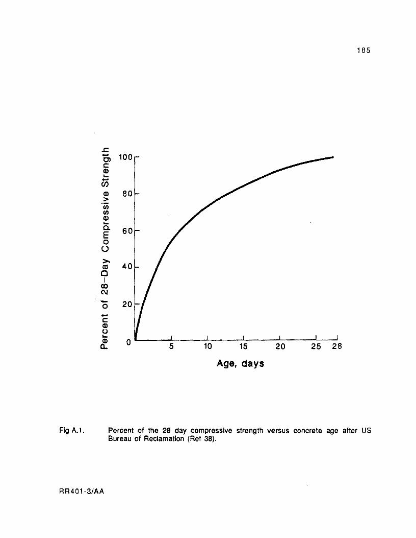
Fig A.1.
185
.I::. - 100 C) c: Q) "--(f)
Q) 80 > Ul Ul Q) "-Cl. 60 E 0 u >-
40 as C I
CO C\J - 20 0 -c: Q) (.) "-CD 0 5 10 15 20 25 28 0..
Age, days
Percent of the 28 day compressive strength versus concrete age after US Bureau of Reclamation (Ref 38).
RR401-3/AA

186
Assumptions
( 1 ) The vertical reaction to any section is directly proportional to the deflection Y,
the proporionality constant k being the modulus of subgrade reaction.
( 2) Zero deflection is at the position of rest on the level subgrade from the initial
deflection w/k, w being the weight of the slab.
( 3 ) Concrete is a homogeneous, linearly elastic material.
(4) Temperature or moisture differentials from top to bottom producing upward
deflections are negative.
( 5 ) Upward deflections are positive.
(6) Tensile stresses are positive.
( 7) The origin of coordinates X is taken at the midslab.
General Equations
Assuming that the temperature is ~TD degrees higher at the top of the pavement than at
the bottom, the curvature of the middle plane of the pavement in the X direction is
=
where
tJ. ,.
v ==
Mx "" DandEc ==
2 12 (1 - v ) Mx
E • 03
c
concrete thermal coefficient of contraction and expansion,
Poisson's ratio of concrete,
bending moment in x direction per unit width, and
as defined above.
The equilibrium of any small element of the slab requires that,
RR401-3/AA
(A.3)

where
= -K· Y
Solutions
Combining Eqs A.3 and A.4 and introducing the radius of relative stiffness, I
4 dY
14 .., + Y = 0 dX
1= 2 1 12 (1 - v ) k
187
(A.4)
(A.S)
(A6)
At the edge X = U2, where L is the slab length, the bending moment Mx and the
vertical shear dMx/dX must be O. Therefore, the following solutions are correct for
deflections:
Y = Y 8..fi • COS (
~ -X ) -(t;) __ -= + 1t e 1 • ..fi 4
(A. 7)
where Ye is the deflection at the edge:
RR401·3/AA
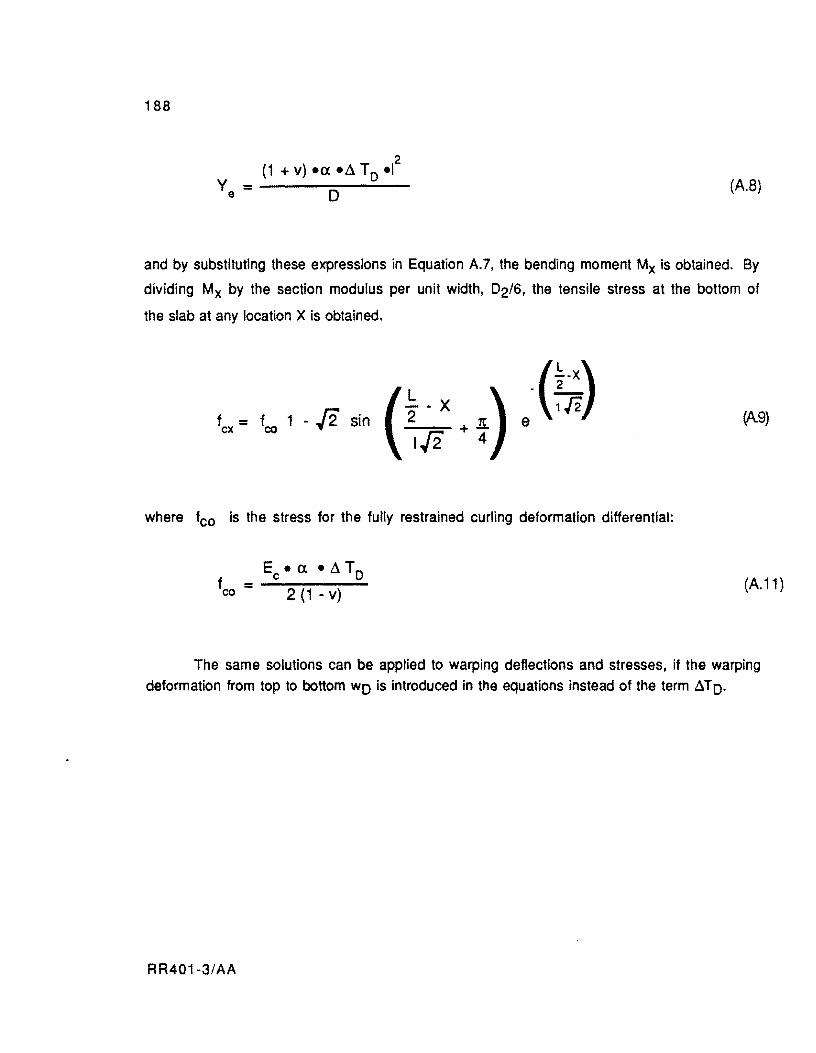
188
2 (1 + v) -ex -~ TO -I
D (A.8)
and by substituting these expressions in Equation A.7, the bending moment Mx is obtained. By
dividing Mx by the section modulus per unit width, 02/6, the tensile stress at the bottom of
the slab at any location X is obtained.
( ~.x ) -(~) _-==- + K e 1/2 4
(A9)
where fco is the stress for the fully restrained curling deformation differential:
Ec - ex - ~ To f =-----co 2 (1 - v)
(A.11 )
The same solutions can be applied to warping deflections and stresses, if the warping
deformation from top to bottom wo is introduced in the equations instead of the term ~TO.
RR401-3/AA

APPENDIXB
USER MANUAL FOR COMPUTER PROGRAM PSCP1

!!!!!!!!!!!!!!!!!!!"#$%!&'()!*)&+',)%!'-!$-.)-.$/-'++0!1+'-2!&'()!$-!.#)!/*$($-'+3!
44!5"6!7$1*'*0!8$($.$9'.$/-!")':!

APPENDIX B. USER MANUAL FOR COMPUTER PROGRAM PSCP1
This appendix provides the necessary input data instructions for operating the PSCP1
program. The user should refer to Chapter 6 for criteria on the selection of appropriate
values for the data. The specification of a run should consist of one alphanumeric card with a
description of the problem. followed by cards defining the problem. concrete properties.
concrete compressive strength-age curve, slab-base friction relationship, k-value of slab
support, steel properties. concrete temperature data for initial period, time and amount of
prestress applied at each post-tensioning stage (at initial period). and temperature data for
subsequent periods. The following pages provide a guide for data input. It should be noted that
"real" variables can be placed anywhere in the available field but must be punched with a
decimal point. Integer numbers, on the other hand, should be right justified in their field and
punched without the decimal point. Alphanumeric variables allow the use of any combination
of numbers and/or letters in an available field.
RR401-3/BB 191
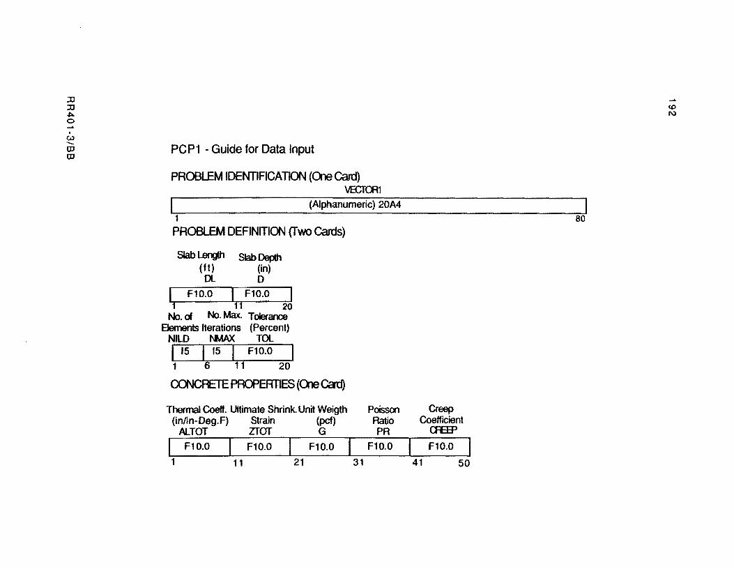
:JJ :JJ
""" o ..... . c.u --OJ OJ
PCP1 - Guide for Data Input
PROBLEM IDENTIFICATION (CXle Card) \IECl'CR1
I (Alphanumeric) 20A4 ---~----- I 1 00
PROBLEM DEFINITION (fwo Cards)
Slab Length Slab Depth (ft) (in) Dl 0
~1().OJ F10.0~ 11 20
No. cl No. Max. Tolerance Elements Iterations (Percent)
NILD I\t,,1A)( TOI.. I 15 I 15 I F10.0 I 1 6 11 20
CO'JCRETE PROPERTIES (<Ale Card)
Thermal Coeff. Ultimate Shrink. Unit Weigth Poisson Creep (inlin-Deg.F) Strain (pcf) Ratio Coefficient
ALTOT ZTOT G PR <H:EP
I F10.0 F10.0 F10.0 F10.0 F10.0
1 11 21 31 41 50
..... 1'.0 N
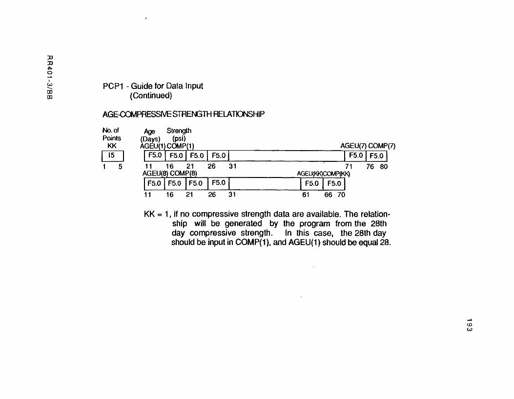
)J )J ~ o ......
I
VJ -... OJ OJ
PCP1 - Guide for Data Input (Continued)
AGE-CClv1PRESSIVE STREf+.6TH RELATJCX\ISHIP
No. of Points
KK
~ 1 S
Iq:J Strength (Days) (psi) AGEU(1,COMP(1) AGEU(7) COMP(7) I FS.O FS.O I FS.O I FS.O I I FS.O I FS.O I 11 16 21 26 31 71 76 80
AGEU(8) COMP(8) AGEU(I<K)CC.MP(KK)
I FS.O I FS.O I FS.O I FS.O I I FS.O I FS.O I 11 16 21 26 31 61 66 70
KK = 1, if no compressive strength data are available. The relationship will be generated by the program from the 28th day compressive strength. In this case, the 28th day should be input in COMP(1), and AGEU(1) should be equal 28.
<D VJ
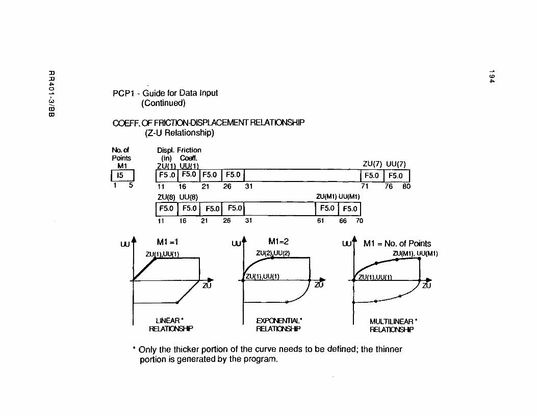
::0 ::0 ~ o ..... . w --In In
PCP1 - Guide for Data Input (Continued)
ca=FF. a= FRICTKJN-OISPlACEMENT RELATIONSHIP (Z-U Relationship)
No. of Points
M1
DO 1 5
Oispl. Friction (in) Coeff.
ZU(1) UU(1) ZU(7) UU(7)
I FS .0 I FS.O I FS.O I FS.O I I FS.O I FS.O I 11 16 21 26 31 71 76 80 ZU(8) UU(8) ZU(M1) UU(M1)
I FS.O I FS.O I FS.O I FS.O I I FS.O I FS.O I 11 16 21 26 31 61 66 70
w M1 =1 w M1=2 M1 = No. of Points
LINEAR· RElATk:f\S-F
zu
E><P<l'EN1lAL. * RElA~
ZU(M1), UU(M1) .. ,
MULTILINEAR * RElATO\ISHP
zu
... Only the thicker portion of the curve needs to be defined; the thinner portion is generated by the program.
..... CD ~
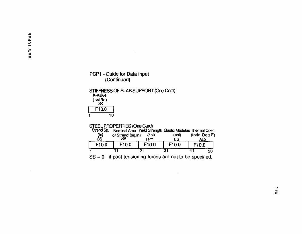
:0 :0 J:>. o ....... . (.) --OJ OJ
PCP1 - Guide for Data Input (Continued)
STIFFNESS OF SLAB SUPPORT (One Cad) K-Value (psi/in)
SK
[ F1D.O I 1 10
STEEL PROPERTIES (One Cad) Strand Sp. NomilaI Area Yield Strength Elastic Modulus Thermal Coeff.
(in) of Strand (sq.in) (ksi) (psi) (in/in-Deg.F) ss SA FPY ES_ALS
I F10.0 I F10.0 I F10.0 [flo. 0 F10.0 1 11 21 31 41 50
SS = 0, if post-tensioning forces are not to be specified.
....... <0 01
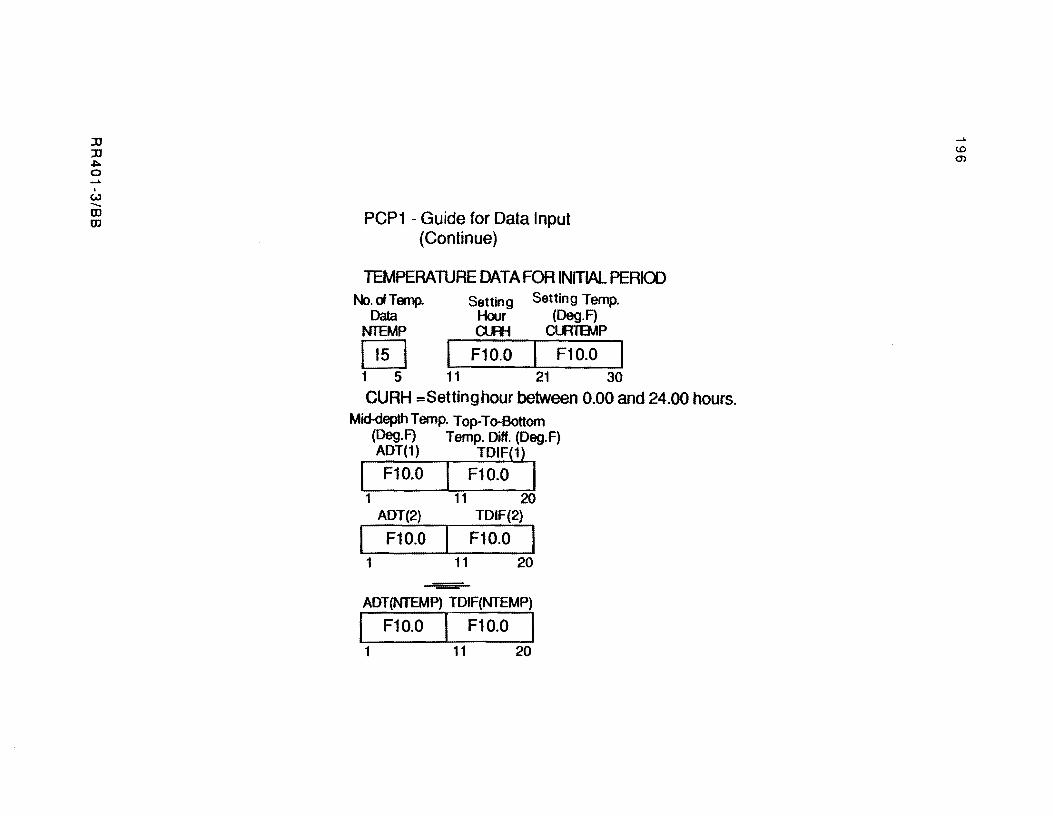
:lJ :lJ .".. o ....... . UJ ...... m m PCP1 - Guide for Data Input
(Continue)
TEMPERAlURE DATA FOR INITIAl PERIOO No. of Temp. Setting Setting Temp.
Data Hour (Deg.F) NTEMP OJI-I Cl.JTIBAP
~ F10.0 I F10.0 1 5 11 21 30
CURH = Setting hour between 0.00 and 24.00 hours. Mid-depth Temp. Top-To-Bottom
(Deg.F) Temp. Diff. (Deg.F) ADT(1) TDIF(1)
I F10.0 I F10.0 I 1 11 20
ADT(2) TDIF(2)
F10.0 I F10.0 I 1 11 20
ADT(NTEMP) TDIF(NTEMP)
I F10.0 I F10.0 I 1 11 20
....... (0
Cf)
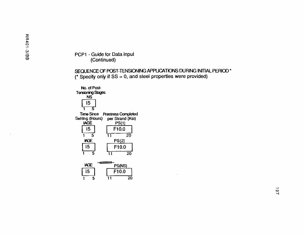
lJ lJ
"'" o , w ....... w w
PCP1 - Guide for Data Input (Continued)
SEOOENCE OF POST-TENSIONING APPUCATJONS DURING INITIAL PERIOD * (* Specify only if SS = 0, and steel properties were provided)
No. of Post· Tensioring Stages
NS
~ Tune Since Prestress Completed
Setting (Hours) per Strand (Ksi) IAGE PS(l)
[@J I F10.0 I 1 5 11 20 W?E PS(2)
@] F10.0 I 1 5 11 20
W?E
[@] PS(NS)
I F10.0 I 1 5 11 20
CD
'""'"
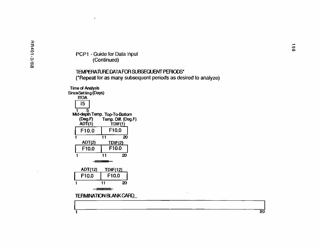
:0 :0 ~ o .......
I
Ul --OJ OJ
PCP1 - Guide for Data Input (Continued)
lEMPERAlURE DATAFOO SUBSEQUENT PERICD3* (*Repeat for as many subsequent periods as desired to analyze)
Time of Analysis SinceSetting (Days)
rrOA
~ 1 5
Mid-depth Temp. Top-To-Bottom (Deg.F) Temp. Diff. (Deg.F) ADT(1) TDIF(1)
I F10.0 F10.0 I 1 11 20
ADT(2) TDIF(2)
F10.0 F10.0 I 1 11 20
TERMINATICX'J BlANK CAAO ...
J 1 80
....... CO Q)

APPENDIXC.
CODIFICATION OF DATA AND OUTPUT FROM COMPUTER PROGRAM PCP1 FOR
THE DESIGN EXAMPLE PRESENTED IN CHAPTER 8

!!!!!!!!!!!!!!!!!!!"#$%!&'()!*)&+',)%!'-!$-.)-.$/-'++0!1+'-2!&'()!$-!.#)!/*$($-'+3!
44!5"6!7$1*'*0!8$($.$9'.$/-!")':!
I
... .. c o
= 0
~
2
~ q
~
! c \!
"" .. z ~
RR401-2/CC
:i
·
::!
· I
..
a
· · II
i
"
..
·
-.
·
\AI
:c
s III ,. -y
" II
UI
'" -. ~
"T l-'I -. ,
""[
""'ii" • "Y ~ .. --",
"T
ll. . a ~ .. '" .. , \
::r 'iii .. :t' It
-q .,
• -· " ,., 'lIo
· t\
::to ".-
· Q ... .. ~
· .-et • 4)
'" ~ · a
... II>
· Q II'l
ft ft ... ~ · N a
"" '" · " N IA " - ~ . · a
II> N
· Q -. ~
III '. - 0 . ft
-6 · II'l -"" " . " .. IA " .. -. · " 'OJ W .. ...
-", - • • - - ...
1&
"
Ii
I"
If
,-II
•
Iii
.,..
.. ,f '0
· a ~ · 0 .. ..
-1\ I-.. -. .. -1ft
Ii
.. · .
..... c '" .,
II
.. -... .. .. ~ .... e If
.:l . . . Ii
. -N co • .. Uo · • .. - ..
Cl . --... · . . . . . . . '" III III "" a
41\ .. ... .. 0,3 -
201
202
, 0 ~ ·
!;
I · k
... t Go
::: l!
· III
"" ... ~ :; C 0
.. •
liI III
.. • 0 · Ii :!! 0 u
0 111 ·
jl I-
i I iii
- .
l! II
- -- U\ ::t "" 16 IA 6 .. m - ;::r . U\ . .~ . . U ., '" ... -a ill 6. .. .& It A .a - .N
• - - tl - I I I I • ::I ~ , " g
'--- -. z 2 ..
~ b .. a -c ~-~ - N 0 - -'II . . In . . . . . . ; f' l' LJ! a. 6 11\ ,.. A\ n If ." ,.. r-~ - 1J1 11\ .to .a - "'"
. 4.\ .... ... ~ ..... U\ -
RR401-3/CC
203
I i
t=F Ii
:;
I - " ... ~
&! l! ~
"l s=-t= I-
... I~ 0- j c
Q
. -. iii 1I
,. • Q 11 I; l!! Q ..,
; I~
/I
§ I-
lO III
.. ..
.. 1\
. . :to :t' IJI 11\ !P ,... Q - .n - () ... • .. . . . · . . . ~ . . .... a ... 'C • ... I~ I. iJI lJ\ tJ . () ... .. - "" - • • • , t I • - - -- !!
z 0 ;:
a .. .., Col it; - . · . . . . . 1ft . . . ...
1I U\ () (', Il1o I'" ~ .rI. la w () .... ... a- - -s a ~ - 'Ii " <!- (!" .. " .... .. -s "" 11\ 'IF III ll\ ... -
RR401-3/CC
204
I · ~
~
I · . -... '" ~
e i!
.. I"
... ... ; I· .. 0
~ I-
i! I ill
,. l1li
0 · III l!! 0 v
~ I ~
· I"
.-
~ i -..
~ N
, ;: N
i-- r-- •
f-- I-~- ;;;;;;-~
t\\ " 11\ - In ---;-
~.:; . . . . .
--"'-~
iII\ ::!> ;:t .::t ~ ~ ,... • • I ~ - --_.- . -- - 1--. - - f-- ~
-- -. -- -Z 0 c-- - - - ~, -. ;::
I~ ... _. _ .. --~- --. I--v
.;: ~- - . ---;- .... - --;:: J-t-
. . -~ -,. z : C\ tl ... -%-~ IA ... IA • -:.- -
RR401-3/CC

:Xl :Xl ~ a ..... , CAl -o o
............ cCtCC ........... 11 ........ , .... eeeeeee .............. 111 .... .... ce .... .. .. 1111 .... .... t:e .... .., 11 .............. CC .. ............ 11 ............ te .. .......... 11 ... cct:ceec .. .. 11111111 .... eecee .. .. 11111111
••••••••••••••••••••••••••••••••••••••••••••••••••••••• • • • aMaL'SIS Of .. llSIILSSlO tONellll .. a.l"lN1S • • CONSIOlIIN& IH[ INlLaSIIt: • • .aIURL Of 1HL SLaB-Ba~l flleilOM feat:lS • • •• lRSION ., tLBRual' ., •• , • • • • ClN.LI fOM I.a.S .. OliaIIOM IlSlalCH • • IHl UNI'lRS.I' Of Illas al aUSI.N • • • •••••••••••••••••••••••••••••••••••••••••••••••••••••••
N a VI
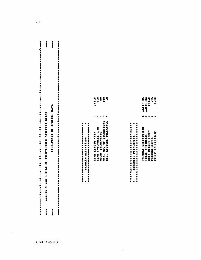
206
• • • • t • • I • • • • • • -r • • I • • • • • I I I I • • • • I I
• I • • • • I I I I • • • • I t • • • I I • • I I
• •••• A .".,.A. T •• A •• ......... . .., ... I I •• • I 1ft .-.-A &'II • C &'II ..... • .. • •• I c I A" • IS I • • • 0 • • • ~ • t c c • II II II II II II II II .. II
~ a I • 0 .- • • • • 0.., I .. .., I • • • .'" • • • I • '" I • • o. • • • .- • • • .. -. • • • • .. ~ • • • • •• • • • I .., 0 I • • - c.- • • .., .. -I » I • • ... 0.~ • • .. 101. • • • • • • • ........ 0 • • 1.1 ... 1.1 .., • .. • • • • 101.0.-'" • 0. .. "' .. ... I ... I • •• .IIJ'-- • .- . IoI.C-O", I 0 f I • ::.. .- .. .., • ... ~ . ..... • ~ • • -. I:· ... il • •• * ••.• • , • • •• "'"a • a. -::1: •• I 0 • • -. "''''1.1 0 • .... l.Ialol • .-I .., I: I • •• a- • '0 • ... 1:_ 0 • • w • • .... ""'z-::. ... • g. ~0.-.'"
• • .., • • .... .... .'" • •• c ::ao t 0 I • .... ... • L. c. "'L I ... I • o. .HD 0 •• • • ••• IIIt ...
• II: • • • ... • •• • .... .. --- .... • .. • • c. .... 0 .... • -. zga:l. I t • ..,. 0111t.E. • .... "'-~LU I !i I .. •• • • • • • • I: • ~: • • • • I a I • •• • ::.. I III I • ... • U • • ... • • • .. • • lilt • • • • • I ... I • • • • I ~ I .. • • • • • • • • • • 0 • • • • • I • I • • • • • • I C I • • • '" • I ... I I .., I • ... • • ... • • • I I .. I • • • • • I I I I • • • • .. • I I I I I I I I • • • •
RR401-3/CC
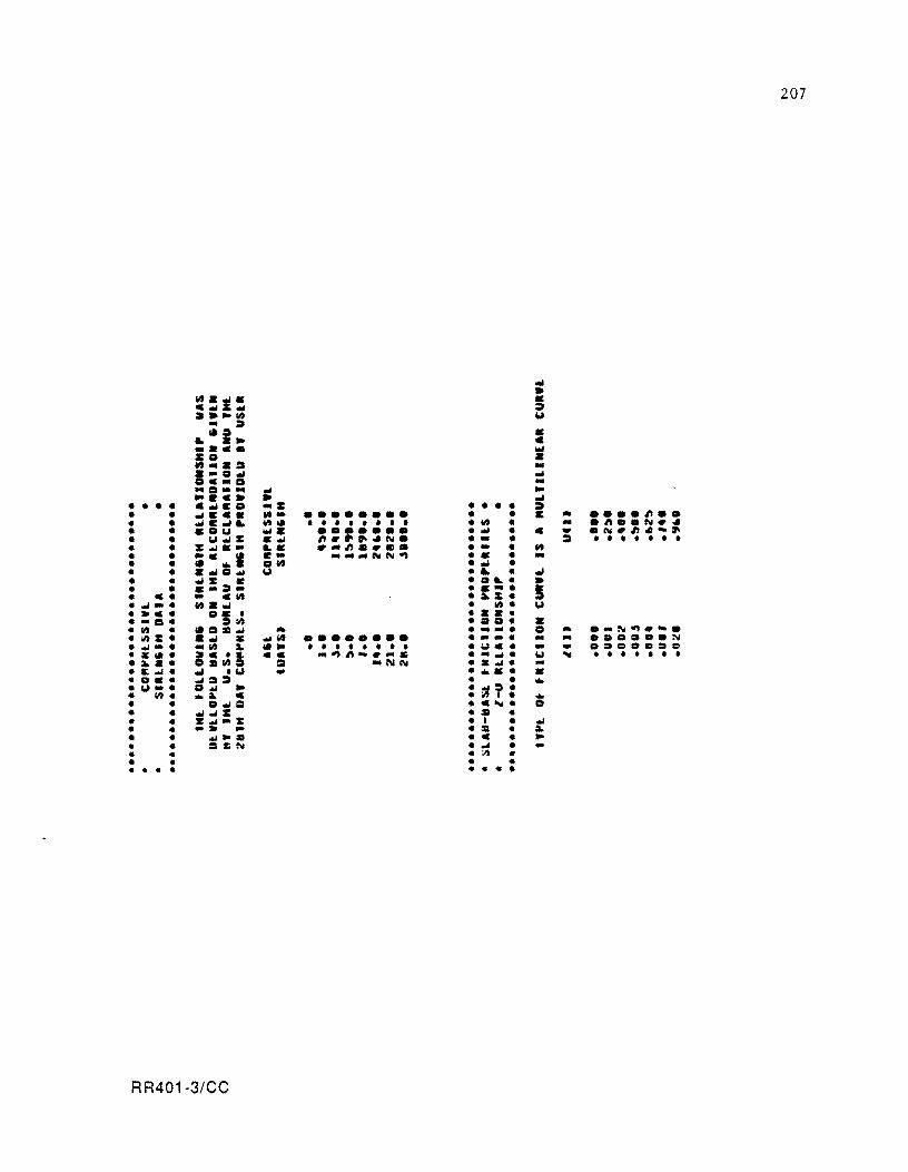
207
... • 1It·1· • c ...... :II a.""1It w
• :II 1I:a • &. .... • •••• ...
2:0 • tIt •• :a .. • -0 ... ... Oc.O • -0-- ... ... .... c • • ..J
• • • • .... CO .2: • • • • :II • • ... C •• !It- •••••••• • • C • .... "' .. • ... C..J&. .. III • • • • • • I • • lit • .. ."' •• N •• • .01.1 .... ••••••• • ... • • .. .1\1."' .... ,. • "" ... :1: .... "'''''".1\1. • • • ::::» I • • I I • I
• :1: .... - I.. . -"., .. .,. • - • .. • ""c I C-• __ 1\11'\1"11 • • • • • II ... o lit • ... • • .... 0 ... "" • &. • ..J
• "':1: • • DI. • • • c-:II- • c· • I c. - C!lt • a.z. • ... -. ...... • lit • 1.1 • C. O! • • • • • • ... c=t. tot • DO • • • !It • 1Ic=t .... • • .- • 0 • .... :\1"11 .....
• ;nz· .... • ... 1It •••••••• • -- • - - ••• ca •• N • ..,-. • 1It :a- lii'" I • • • • • • • • wc. - ... ..D .... • 1:111· I C'" cc ... ..,,,., ......... • ...... 1.1 ~ • • • • • • • • a. •• lIlIta :a -NI\I • . ..,. -• .. ..,. ..J .w ... • ••• • • ac. ..,a:ll • • ... • ""-. 0.., ... • ~T: • lit. .a- C • • • • o..,c=t • C~. c=t • • .., ... :1: • • • • • z..,-1I: • I • .oj
• • -at ... • :II • :a. • • .., .... • C • ... • • • SoN • ... • -• • • ;./I • • • • • • • • • • • • •
RR401-3/CC
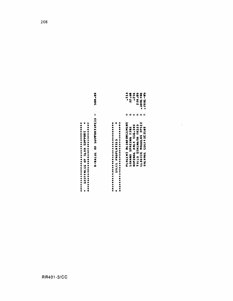
208
• "' • .0=.'" • ........ = • .. '1'\1 •• I
• '1'\1 ' • .M.M • .., ..... '" 1'\1 •• ......
• • II II II II " II II
... ... • • • -. • • • .. ... • • .. • • • .. ..... • • ... • • .M ....... IIt· • • .. • • c .... IIt ... • -• K • • ~ ... ..... ~ • .: • 0 • • -. ... a. ... ...
0 • t • • • lit 1It-. :I. • • • 0 ..... :::1 ... .. • ::I • :I) • ... -.M • ::I • :I) • ~ • ....... ::1 .. lit • • ... • --'.M.::I~ • .. • -• ~C • .M=;I :II • = • •• ... e.lE;.! 01 • • .M' :I) -.M • .M • :a. • ' .. .M1It-..M :I) • ::I • ;I' .:::101 _e
• .oJ • •• ..... :::1-1: .. • e • :I. • ;.!C"oJlltZ c:I • • • • ZZI:.MeoJ .. I • .oJ • .M-:::I ... oJ: :I). • .. ... • ..:I) .... ~-:I) • • .oJ • ., .. • -• • •• • lit • .. ... . • ..
• .. .. • • • .... .. .. • ... .. .. .. lit· • • • • .. .. .. .. .. • .. .. • .. .. .. . .. • ..
RR401·3/CC
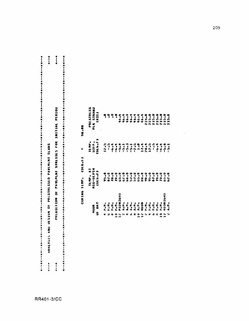
209
• • • • I I I I 1 I I I • • • • • • I I I I • • • • 1 I I I • • • • I I I I
• • • • I I I I • • • • I I 1 I
• = • 111= • '" • III. I ... I .... e ... I • I ..... •••••••••••••••••• • loW • ,..,..C/I • • • • • • • • • • • • • • • • • • • It. • CIICIIar: 44oQ444oQI'II'II'II'I.tI.tII'I I I loW - ............................. I
"'" I •• eld\H\! (\; 1\0 :'\I (\;
• e • • It. .... • ... • • It. I ... I • I ... I • • • • ... • ... I ... 1 • • .... • III '" a. ... • 1'I1'1 •• c ... ~ ... l'Ic •• I'II'1 •• c ... • :1:1 ... 1: ... • • • • • • • • • • • • • • • • • • 1 e II ........... (\;1 441'11'11'11'1(\; ....... (\;1 441'11'1 1 ..I 11'1 -== ... I I I 1 1 I 1 ... (\; ... 1 I .. I • III .... -• IIJ I .. IIJ ... 1 I! .... ... • .... • • • It .. II
I .... III .... .. = ...:: • e - ... e_ ... • L • • a. ... •••••••••••••••• D. 1
"'" I ..... • • • • • • • • • • • • • • • • • • • I = ~ 1 • a. =101 I'I"'CDI'I~D"''''I'IDDI'I''':I:IDI'I(\;
• .... • It. C I .... .... ~~444.t11'1~= ............. 44 • IIJ .. • c ....== I IIJ C I .... ---I .... L I C • :I: • • .. .to. • .. I IIJ CI I • - -I "'" I ... :: :: • :I: • • • OIl .. • a. CI • ::I ... ... I ... I Col ... • • • •• • • • • • z • • • • • z • I ... - I IKe 1tItI:It:lI:E~EE:lEItItItC:lE
• 0 Col • == • • • .... I • • I • :::I • I • I I .. • • ... • :::I ~a.~a.Eccccca~.a.a.a.cc
I Z ::I I z: ... I :t;
"'" I :I "';IQ ::O~N .. ..II:a ::O~ ~ .. 4 ;t'D~ :'Ii
• .. ~ • ... - ..... ...... • ;II a. • I ... I I ::I I • • • :I • I Z I , ., I
• • • Il • I .. I I :Il I • ... • • ..I • I C I I Z I • c • • • I I I I • • • • • • I I I I I I I I • • • •
RR401-3/CC
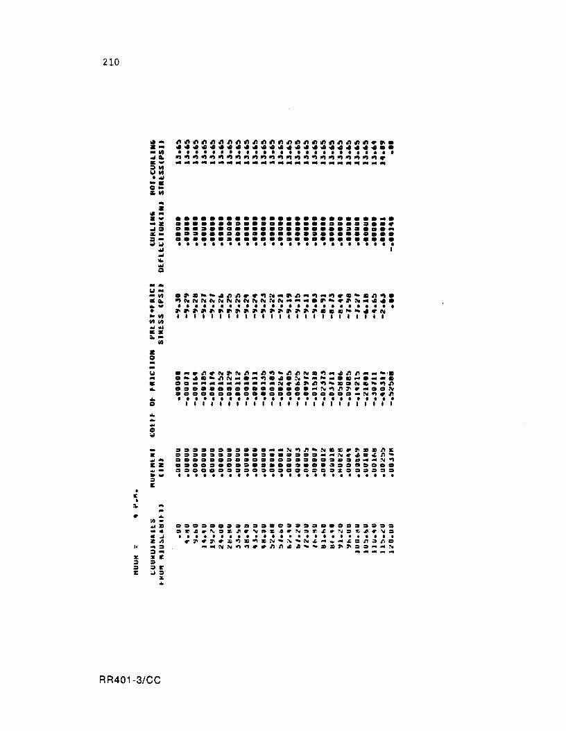
210
" ... . --.. ..... .... :» .. 101 .. ·wI .... 0'" e ..
... • " ... .... -. ... :::11 X-:»---wi ... ... ...
Q -... 101--III ... ....... • ..... lit III ... otJ •• a.-
III
:I: 0 --101 ... • ... ... 0
... ... ... 0 --II: ...... ez .... -..... ::I e
• I: • a. ... • ..
:/I ... ... ZI ... · ... Z;;)
Ii -:I :I ...
31: S I! ::I • • .t' % oJ.
S ..
RR401-3/CC
............................ ......................... ~ •••••••••••••••••••••••••• •••••••••••••••••••••••••• •••••••••••••••••••••••••• • • • • • • • • • • • • • • • • • • • • • • • • • • •
.... ~ .n ~ I'll .. I'll .n ... I'J ., ... .n .n N D ., ... 4 .n .n ........ 'II .-411 ... .nN ....... .,1I4.~ ............ II ......... .
..- ....................... N~4 .. .n., ..... NII ... .,.n ••••• O •• O.O •••• O ... N.,.n~~ ..... N ..o ...... O .............. N.,~.n • • • • • • • • • • • • • • • • • • • • • • • • • • """.", •••• ,1,,1,111,1
................. N.,.n ... NDZI.~ZlD.nZl ..................... N.4 •• .n ...
.......................... N~ •••••••••••••••••••••••••• ~ ••••••••••••••• = •• z •••••• • • • • • • • • • • • • • • • • • • • • • • ••••
•••••• = ••••• = ••••••••••••• .~~.'.~~.N.~~.N.r.~.~.~~.~ . • ••••••••••••••••••••••••• • ~.~.ZI~D.,DN ... ~ ... N •• _- •• .n.r.. _ ... NN.,., •• .nn~~ ...... DZI~~ •• _.N
1IIIIIIt'-'." ....

• C • ~
.;;,
I'
:a-::;)
::I l:
~ ... z ... -~ ... '" .... :::::I~ ~~ ."" -::.: 0-;g~ ...
z ~ ... zw ... z ~o .... :::::1-
-~ "" ... ... "" Q
-... ~ ... ... ~ . '" ... -• -~ ~I/S ....... ::.: . . -Z o ...
010 010 .. :;) w
lIS
------------------------.. ------------------------.. • • • • • • • • • • • • • • • • • • • • • • • • • • 111'111111111111111111111
......................... -•••••••••••••••••••••••••• •••••••••••••••••••••••••• •••••••••••••••••••••••••• •••••••••••••••••••••••••• • • • • • • • • • • • • • • • • • • • • • • • • • •
~~ •••••• ~~~N .... C.-~.~.N~C~ • C ••• CC ••• C •••• --.~~~ •• ~~N • • • • • • • • • • • • • • • • • • • • • • • • • • • ........................................................... ~-~~ ...............................................................
. .. ~.N~.~.~.~.~ .... -.-~~ ...... N~ .• ~ ..... ~----C~~N.~N •. ~.-.-~ ................... N.-~ ..... -~ ... -•. •••••••••• = ••• = .... N.-_~~~~~ •••••••••••• = ............. N~~. • • • • • • • • • • • • • • • • • • • • • • • • • • I I • 1
.~ ... -. ____ . ____ ~_~~~~_~~4 Z •••••••••••• = .......... ~~ .. ... ~A ........................... N £Z •••••••••••••••••••••••••• ~ ..... = ••• = •• c.= ••••••••• ~ •••• » - •••••••••••••••••••••••••• • I I I I I I I I I r
... "-
;,/I -~ ~ = • • • • • • • = • • • • • :> • • ..== • • • • • .. '" I" ,£l • !I.I:o :II ,£l • ~ :0 ." .D r :'\l :0 :c. .D r '" :0 '1", .l: • '" , ... ~ • • • • • • • • • • • • • • • • • • • • • • • • • • Z ~l <If' :I' .:- .. ;. ~ . ~~~ ... :-. .. ~.t.: ... ... " := .~ Q ., • -:::\ ...... N ~ ... .... r.n /) .Ii • ..... I: :&. ,. ,. • . ... ... :\I :::\ ...... ... ... x I: • ::I ... ;.J :I
X ...
RR401-3/CC
211
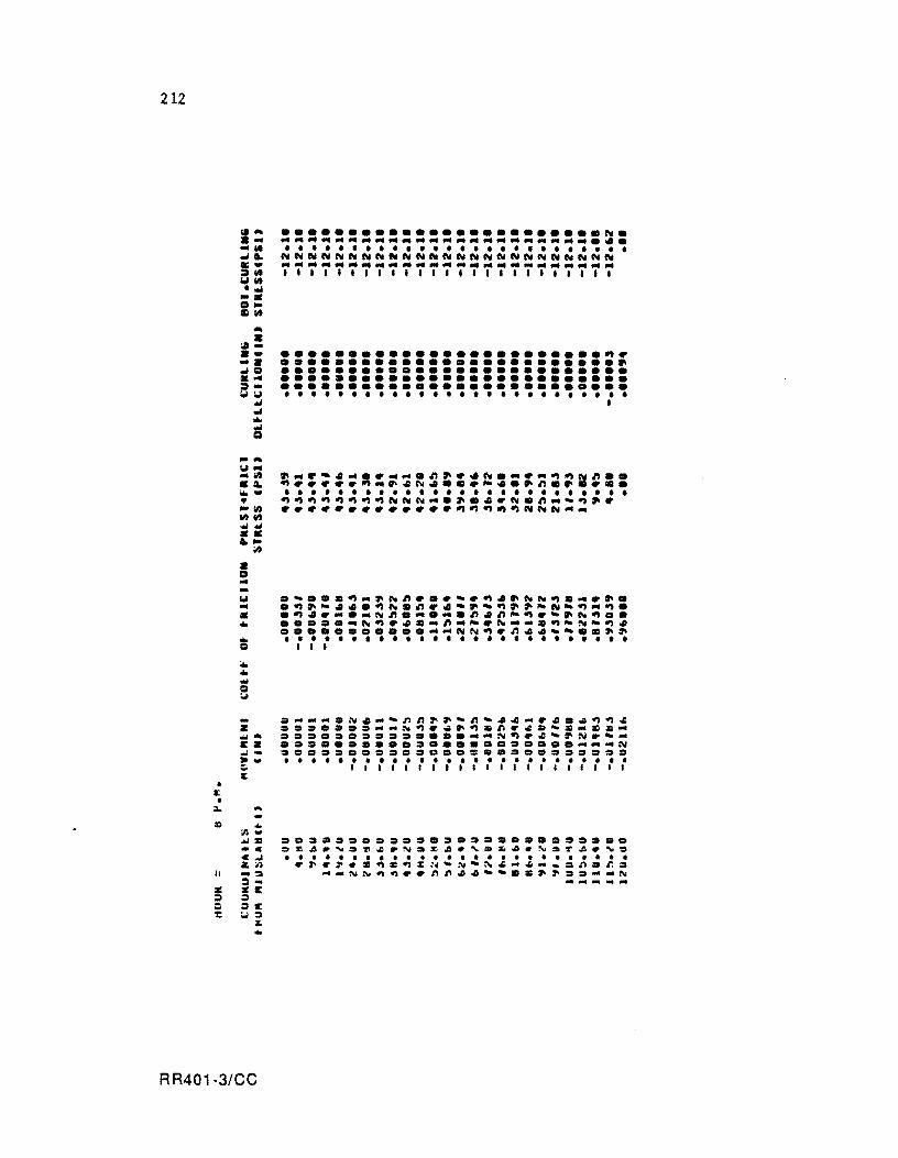
212
• I: •
... • .... ... ... .Ie;) ... :=»-"'''' ,oJ
,oJ ... !l -... "' . ... 1It
• a. ..... • -lit lit lit ,oJ,oJ -.. -• Q .. -'" .. -...
-Z
;II
... -EZ .,/ .. ~-It
. ...
II
... ;II ... M: -C C..l Z;II .. ~ ~ .. SE = =-= :.0=
:II;
•
RR401-3/CC
•••••••••••••••••••••••• N • •••••••••••••••••••••••••• • • • • • • • • • • • • • • • • • • • • • • • • • • NNNNNNNNNNNNNNNNNNNNNNNNN ••••••••••••••••••••••••• 1II111 II1111I1111111111I1
........................ ~~ •••••••••••••••••••••••••• •••••••••••••••••••••••••• •••••••••••••••••••••••••• •••••••••••••••••••••••••• • • • • • • • • • • • • • • • • • • • • • • • • • • I
•• ~- ••• ~ ....... ~.~.N •• ~·~~N~ •• ~~~~~~~ ••• N ••• ~ •••• ~ ••• ~ •• • • • • • • • • • • • • • • • • • • • • • • • • • • ~~~~~~~~NNN ........ N.~ ... -~.~ ~~~~~~~~~~~~~~~~~~NNN ....
==.= ••• 0= ••••••••••••••••• oz~.~~~~.~.~~.,.~~.~.r~.~.
• • • • • • • • • • • ••••••••••••••• .~.~.~~~~~~-N-~~-~-_.n.n.
--NN~~.~nn~~--.~.~ .. --N ... ... ~ .. -
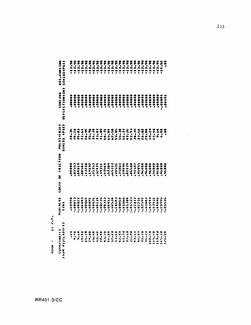
• a. •
.... 101-... lIt .'" ...... • -III 111111 ~.w lIClIC ",.
• • ... •
lit
•••••••••••••••••••••••••• •••••••••••••••••••••••••• •••••••••••••••••••••••••• •••••••••••••••••••••••••• •••••••••••••••••••••••••• • • • • • • • • • • • • • • • • • • • • • • • • • • I
101 .~~ .• N~._~~_ ... ~ .•• ~n ••••••• ... .~ ....... ~n-n~ .... ~~~- •• n ••••••• • .n.nN ... _._~~~~ •• N~n •••••••• ... • ..... ~~nN~--n.~CN~-~~~~~~~~ ....... _N~~.~~--~ .. ~~~~~~~~~ ... . . . . . . . . . . . . . . . . . . . . . . . . . . Q
... ... ... B · .~~~ .... ~.~~N.~=~.~~~N~~-~~~ 2 .-N.~~N-~_ ... ~C~~.~- ... ~ •• ~.~_ ~- ==.= •• - ... N~.n~.=~~.N~ •• ~.~~ E2 ••• = ••• = •• = ......... - ... NN~~~ •• ~ ~- ~.== •••• ==.== ••••••••• I:I.c. · .., ......................... . .. 1I111111111111111I1111111 It
:L. ...
"
... ~_Xl -41 41..1 Z W# -':I ':1-:Ell: ;l ::II:' UD
z: ..
RR401-3/CC
= ••••••••••••••••• == :;rA.~.Z~.N.»~.~.~A.~
• • • • • • • • • • • • • • • • • • • • ~~.~~~~~~4N~N~N~_._ -_NN~~ •• ~~~~ __ Z~~
1:1 .., • ., ,. ••• DO 'L.r.. .... • • • • • or>C .' . :;:;- ... '" -... -...
213
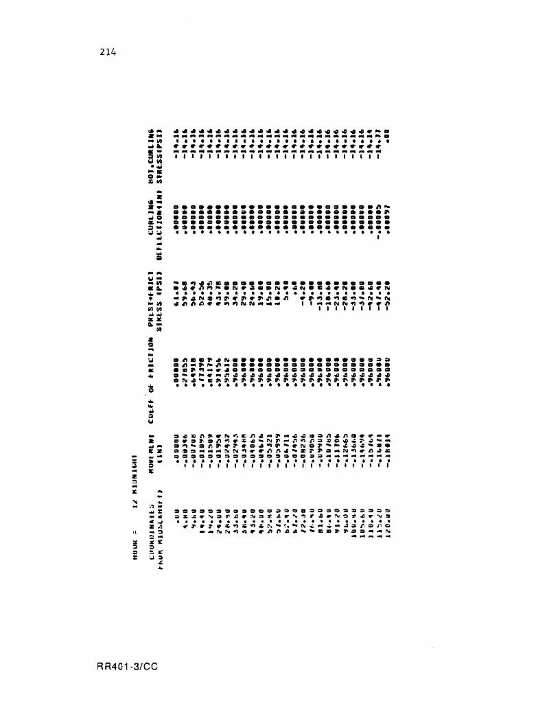
214
la-a-.... 14 ... a.. ... =14 Willi .... -. 1:1-~1111 -• .... a • ..... ..11:1 a .... =-W:.I ... ... ... ...
CI .-W" _l1li • a.. w..-• .", IIiIIIII ...... aa a..-
'" • 1:1 .... -., -• .. .. 1:1
... w.. ... :::I W
-a ... -E • .....
:: •• ;II :::I ... E Z ::I ... It ... N ...
~1 • .... :: _c .... • .11
" ::I
= ... 5 ¥ I:
= ; I: :: ;.I = ~ ...
RR401·3/CC
....................... ~~. ------------------------~ . • • • • • • • • • • • • • • • • • • • • • • • • • • ~~~~~~~~~~~~~~~~~~~~~~~~~ .... _----_ ...... _--------1111111111111111111111111
........................ ~~ ......................... ~ •••••••••••••••••••••••••• •••••••••••••••••••••••••• •••••••••••••••••••••••••• • • • • • • • • • • • • • • • • • • • • • • • • • • 1
.~~n~~~~En ... ~ ....... n~n.~~ .... e .. ~.n~.~~-N~-n~n.~e._~~- ..
.~-.r.~.~ ... ~~-.N.~-~~.--» . .......... ~~~.~~n.-z~~ ... ~~.n.~ ••••••••••••••• e ................... . • ••••••••••••••••••••••••• Illtlllllllllllllllllllll
•••• === ••••• ===.=.=.====~= =~~.~.~~.~=~~r~~r •• ~~~~.~s • ••••••••••••••••••••••••• ~~.~.~~~~~~-~-~~ ... ~-.=n.~ .
.... N~~~ •• n~ •• --cc~~== •. N ...............
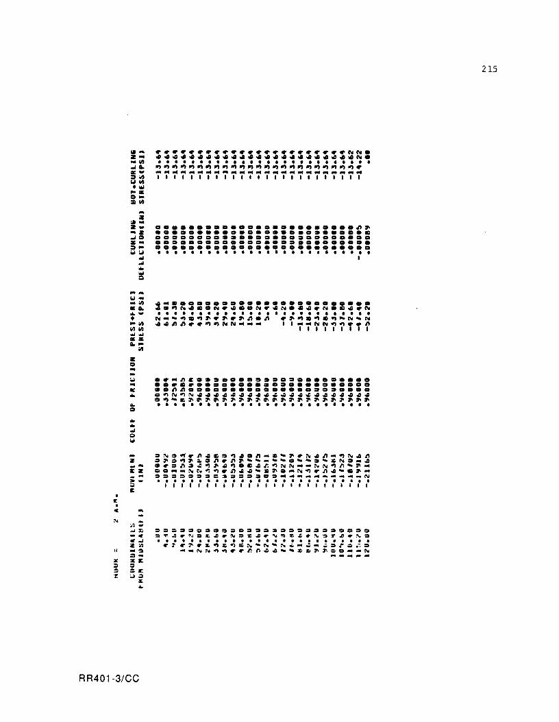
,.-Z ... ... In ...ta. c-::::lin ""'In .\I00I ...
1:1 ... ::Din
... Z
;.t. z_ .... ...tl:l c-::::I" ""' ..
wi ...t .. ... Q
...... ""' ... _In .a. .. -• -In In In ......
--a.-III
z 1:1 • l,J ... c .. ... 1:1 .. .. ...t 1:1 l,J
.. z ....... cz .... :110 ... :I I:
• It •
C .. :\I ... • 1 ,., ... :r:. -. flit ... Z :n
II -~ :I-;II: XI: ::. ::I :I :.: 1: U:I
% ...
RR401-3/CC
........................ ~~ •••••••••••••• O ••••• O •••• C •••••• 0 •••••••••••• 0 •••••• •• 0 •• 0 •••••••••••••••••••• ••••••• 0 •• 0.0 ••• 0 ••••••••• • • • • • • • • • • • • • • • • • • • • • • • • • •
1
~~=~.~~~=~~=n_z~~.:\I~~"~N~~ ~~=~~~=~.n~-~ .. --.--=-ZN=_~ 0.=n=~~~4~.Z~r.~~N"'''NN~n~~ .. =O __ NN~~.~~~_Z~ .... N~.n~_C~'" :I======C~~==.D="'_"" __ ""''''_N • ••••••••••••••••••••••••• 1I1I111111111111111111111
==:====D==.===~O==.==='D=O =~~.N=£~.:\I=~~.~~Z~.N=r~.N= I ••••••••••••••••••••••••• • ~.~.~~~~ZN-N~N_"~ .. ~=rg~D
-"'NN~~ •• nn~~~-==~~:._ ... N ................
215
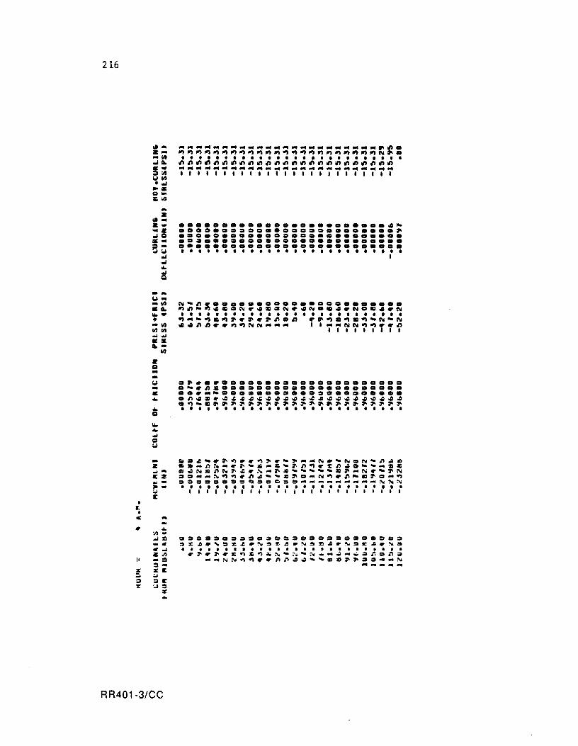
216
• .. •
-OIl
101--1/2 CA. ...... • -1/2 1/2111 .0/ .... c. A.-
II! Q --101 -• ... .. Q
1/2
........................• ~ ......................... ~ •••••••••••••••••••••••••• •••••••••••••••••••••••••• •••••••••••••••••••••••••• • • • • • • • • • • • • • • • • • • • • • • • • • • I
- .• ~_.~~ .. ~~._~ __ N._N.N_~~~ 2 •• _~~_.~_~_~~~~~.zn •. ___ .Z ~- .~N.nN~~.~-~.-----.~-N.-~N E2 .. __ ~~~~~~-_.~._N~.~~.~._~ ~_ ~~~.~D==~=oc.e_~~" _____ ~~N · - ......................... . :;.I 1111I1111111I111111111111 E
c ...
~ ... " .. ..ol%l -c C..ol 2;,11 -::I = ... Z:E :;.I :IE :.1::1
:r: ...
••••••••• a.o ••••••••••• o •• .~~.'.~~.N.~~.N.%l •. '.E~.~. • • • • • • • • • • • • • • • • • • • • • • • • • • .~~~.c~~~~~-~-~ __ ~ ... ~=~.n=
_ ... NN~~ •• ftft~.~_~.~~ .. ~_N .............. flIIIt
RR401-3/CC
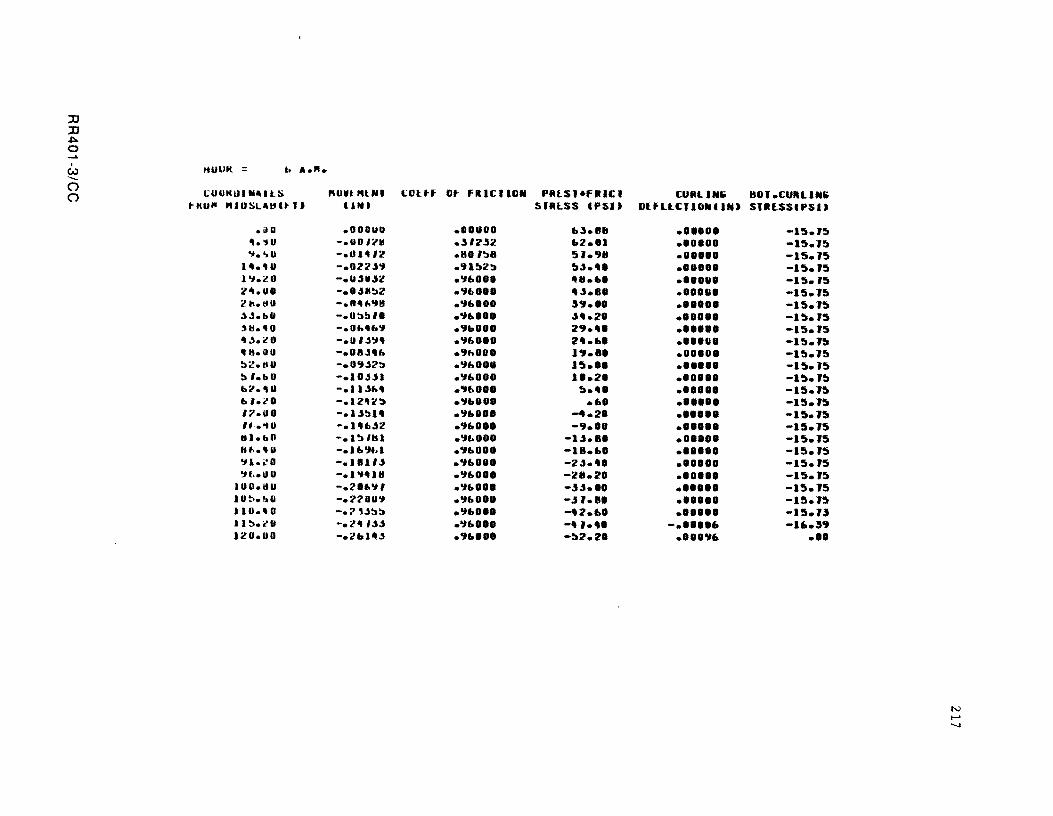
:0 :0 ~ a ..... .
ttUUK = b A.". c.J
---() !;OUMUIIIi"llS Plun "IN' t;Ol.tf ()
t-ItUlil 'UUSL"IHt-' J UN)
• .,0 .OOUUU ".,U -.UO'''II '1.'>0 -.u 1 "'2
1".4 U -.022"'1 1 '.I.i! 0 -.u"o.t:/' :/'''.UO -.0.t6:'Z la..tcD -.n" .... " ,).Sabll -.U3~'0 ~tI •• o -.01.""'1 ,,~. i! 0 -.u'""" • It. II U - •• 8"'" ~2.IHI -.0'1"2::» :, '.bO -.1'''''1 b ... "U -.11"1.' b, • .,. -.IZ"ll!J 11.0. -.l"~" ,,· ... U -.I ... .tZ III.bO -.I:,nu Ii ... '"~ -.1 "'11>1 ..,1.i.'0 -.1 BlI" ..,t .• o u -.1""18
lUO.IIU -.20 .. ..,' I U~.!oO -.2'2'OU'I 110.40 -.2 ""33 11~."U - ..... U" 1:/,0.00 -.lbl""
Ot Fill C II(lN PMlS'.FItICI SfMlSS IP51J
.IOUIO &;'.1111
.;"2;'2 &2.01
.80 ':'B ~l.911
.9 1 !)2:» ~.t.'" • ..,& •• 1 "11.&0 .'1 .. 0.1 .. .t ••• .'1"'00 " ... ,. .'1"'00 "4.2' .'IbOO' 29 .... .'1.,00. 2".&' .'IhOIO J.,. B' .'1hOOU J~." . ..,,, ... 1'.2' . .,,, ... !) .... .'1bO.O .&. .'1"1" -4.2' .9"." -9.'0 .'1"0 •• -I.t •• ' • .,"0.0 -IB.&' .'1"010 -2.t •• ' .'1"'" -211.2. .'1"'" -".t.1I .'1" •• U -.tl.8' .'1&0'0 -l1li2'.&' .'1"0" -',.l1li' .9"'0' -!)2'.2'
CURLIN .. 80l.CURLlN6 DlfLLCIIONIINJ SIItESSIPSIJ
••• 00. -I~.l~ .00000 -I!t.l:» .0 ••• 0 -I~.l~ •• U.O. -l~.l~ .'.0 •• -l~.l~ .,',&1, -I~.l!!l ..... , -l~.l~
.'0'" -l!!l.l~ ..... , -I~.l~ •••• u. -l!!l.l~ .0 •• 0' -l!!l.l!!l .'U'" -I !!I. I !!I .,., .. -1!!I.l!!l ." .. , -I~.l!!l ... ,., -15.1~ ., .... -1!!I.l~
•••••• -15.15 ••• 0 •• -1~.15 •••• 0. -15.15 .0.'., -15.15 .'0'" -15.1:» ., ... , -15.15 .0 •••• -15.1~
.'0'" -1~.JJ
-.""6 -16.59 •• 00.,6 .00
N ...... -...j
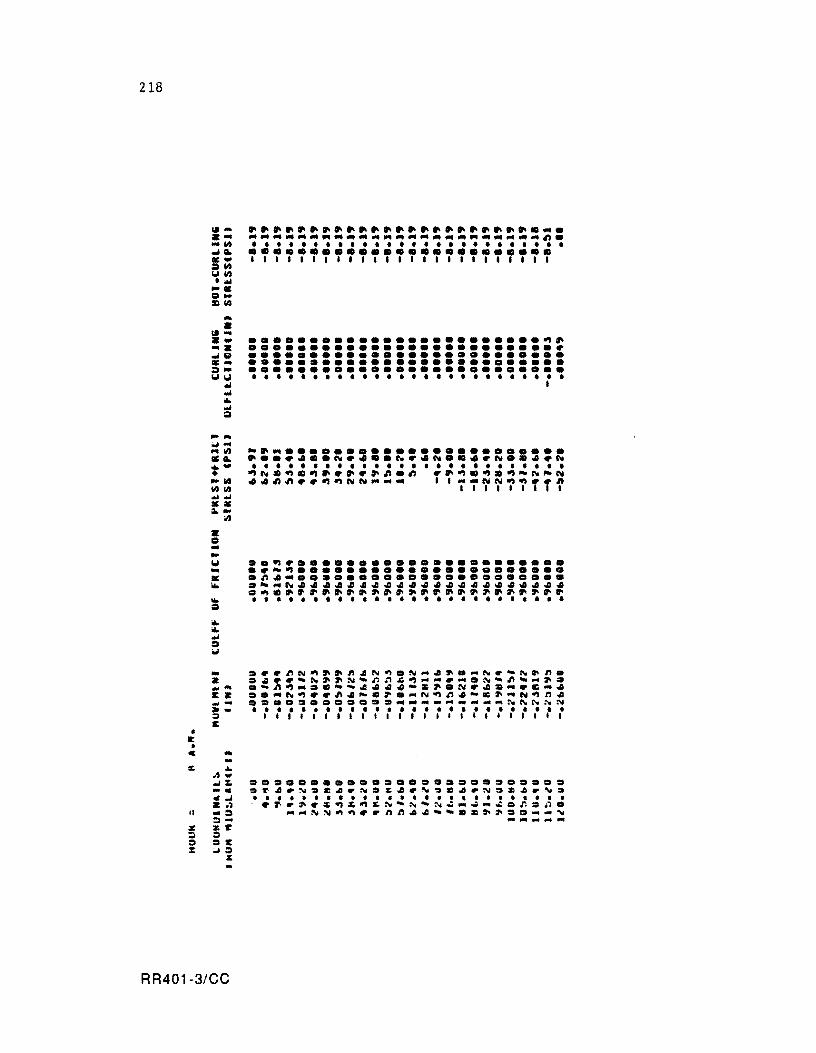
218
• E •
... • ~ ... .... .... .. &I .... ;:,ww
.t .. lot. .. Q
..... ;",I... 1/) ... ...... • -1/1 1/)1/) ...... :1:. ~-
• = ... -w ... I£: ..
:/I
........................ ~~ ......................... ~ •••••••••••••••••••••••••• •••••••••••••••••••••••••• •••••••••••••••••••••••••• • • • • • • • • • • • • • • • • • • • • • • • • • • I
.. ~ •• ~N~~~~~N~.N ... ~~ .... Nr'N~~. Z .~~~'~~~N.~~~~ ... - ..... N.~ .... ~. ~_ .~n~ .... C-~44~~-&~.N~4& ... ~C ... 4 EZ ..... N~~~~4~.~ .... N~n4~c~ ... N~~4 ._ •••• ~ .......... ________ ~N~~N
~ - ......................... . ::l III111I111I1I111111111111 C
C ...
/I
... "'w ... :. •• .,...1 Z ., -= =:11:1:
= :IE ;.J= %
........... ~ ........ ~.~ .. . ~r.~.~~~~.N~:4.N~C~.N~Z4.N~
• • • • • • • • • • • • • • • • • • • • • • • • • • ~~.~rc~C~C~-~·N~ ... ~ ..... r..~. _ ... NN~~~.nn~4'·.c~~~. __ ~ ---- ...
RR401-3/CC
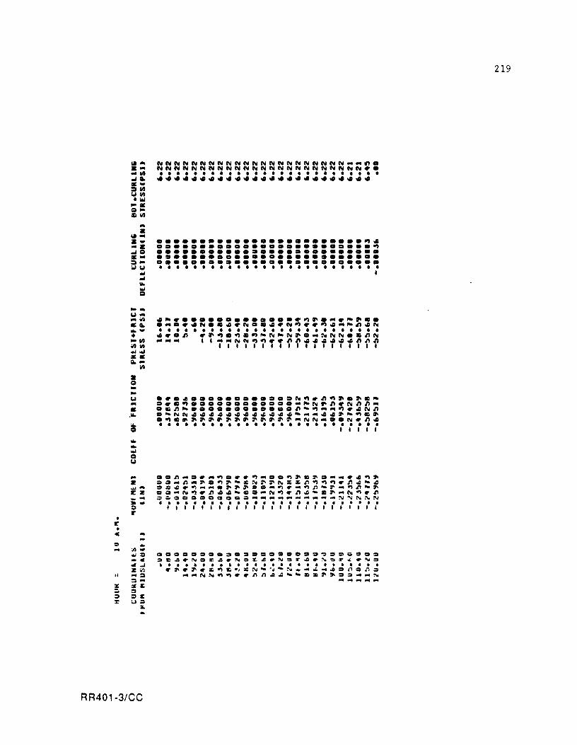
• IE' •
u.'" .... ... IIt .... . -::Jill 1.1111 '10.1 ... 0-=111 ... • u. ... . -... .. 0 .... ::J..,1.1 ..,
J 110.
I!S -... 1.1'" ... ." ... ...... • -III "'Ill ........ •• .... • g --.., .. • ,110.
"" g
... ... .... o 1.1
III
NNNNNNNNNNNNNNNNNNNNNN __ ~. NNNNNNNNNNNNNNNNNNNNNNNN~ • • • • • • • • • • • • • • • • • • • • • • • • • • • •••••••••••••••••••••••••
........................ ~ . ......................... ~ •••••••••••••••••••••••••• •••••••••••••••••••••••••• •••••••••••••••••••••••••• • • • • • • • • • • • • • • • • • • • • • • • • • • I
- •• ~-.~-~.~~~ ..... ~~=~ ......... ~~ · ..... ~ ... ~.~~-C~~~~~~~~~~~~~-~ ~ ..... ~.~ ....... ~~~ ..... ~ .... ~~-~ ... ~~-~ EZ ..... N~.~ •• - ..... N~.~~-=~ ... N~.~ ~. =~~CO=CQOOQ ___ "~ __ ~_~~~N~N » - •••••••••••••••••••••••••• :> 11111'11'1'11111111111111 r
C ...
I:' ...
Ii
... :11-.... = _c .. ..I Z:II ... :> ::I'" se ::I =e U:::I
l:. ..
RR401-3/CC
• •••••••••••••••••• ~.I:'~ ••• .~~.N.C~.ND~~.NS~~.~~r~.NS
• • • • • • • • • • • • • • • • • • • • • • • • • • .. " • "I' ., z. ., &. .~ 2: N ..... ~ ,... :\t ........ '" _ toO ::t J1 = .. '") = ...... NN~~~~nn~~--==~~ ........ N .................
219
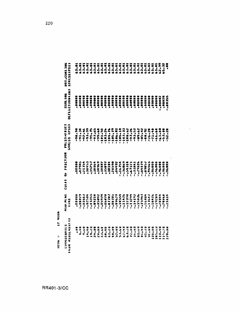
220
2 :::. :::. 11
~ -II
f ."
~ :r
!oI'" •• ... 1It ..... ... ~1It YII) ..... .... = ... :Gil)
... • !oI" ... -. ... = ... :t ... yy
.... ... ... !
...... "" .. -II) ... ..... + "'11) 11)11) ........ •• .. -• = ... ... y ... • ... ... =
:1'1
..................................................................... ~N • ....................... ~~ . • • • • • • • • • • • • • • • • • • • • • • • • • • ~~~~~~~~~~~~~~~~~~~~~~~N~ •••••••••••••••••••••••••
••••••••••••••••••••••• NC~ •••••••••••••••••••••••• N~ ......................... ~ •••••••••••••••••••••••••• •••••••••••••••••••••••••• • • • • • • • • • • • • • • • • • • • • • • • • • • I I
- .~~~nmN~.~n~~4.~N4~~-4~~.~ • .N4.n ... ~~~ •• ~n~~~~~~.~~.C4 ... .... • ~~r.~N.~.~~~n~~N-.~Z~~N •• ~ ~ • ..... N~~nn~~.~ .... N~~r.n~-.~ ..... _~ OQ~O ••• Q •••• ___________ N~~
~ ~ ......................... . ~ I I I I I I I I I I I I I I I I I I I I I I I I I E
... .. :1'1-... :1 -.. . ~ 2:1'1 -:I :I-'ZI: = :IE :oJ:::'
;oJ; ...
•••••••••••••••••••••••••• .EA.~ •• A.N •• A.~.~A.~~~~.~. • • • • • • • • • • • • • • • • •••••••••• .~.~.~~Z~CN-~-N£ ... ~ ... _.r.:::.~. __ NN~~ •• nnA~--.C~~.:::._ ... N -- ...... ....
RR401-3/CC
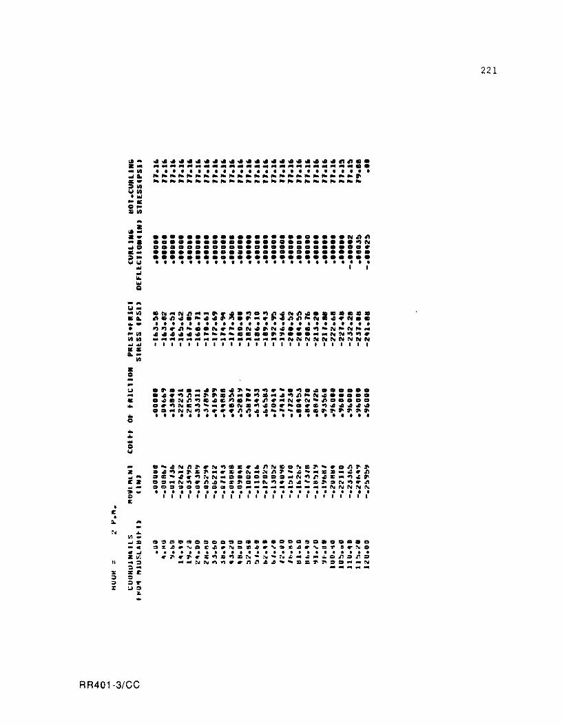
• II: •
III'" . --lit .. &, •• = lit Col lit ..... •• Q. :gilt
... • 111-
lII.... .. Q .... =""'Col .. .. ... ....
Q
..... w-~ C&, .... • .1/:1 1/:1 lit ....... •• &, ...
• Q ... lit
~~~~~~~~~~~~~~~~~ .. ~~.~~ .. ------------------------.. • • • • • • • • • • • • • • • • • • • • • • • • • • ~~~~~-~--~--~~~-~~--~---~ -~------~-------~-~--~---
••••••••••••••••••••••• Nn~ •••••••••••••••••••••••• ~N •••••••••••••••••••••••••• •••••••••••••••••••••••••• •••••••••••••••••••••••••• • • • • • • • • • • • • • • • • • • • • • • • • • • I I
w .~._._~~.~~-~~.-.~.~ •••••• ... .~.~n .... ~Cn_.~C ... ~~n-N~ ••••• • .~.Nn~C~C~.~.n .... N.N-n ••••• • •• ~~C~- ..... NC~~ •• - •• C~~~~~ •
..... NN~~ ••• n~~.--- .. C~~~~~~ • • • • • • • • • • • • • • • • • • • • • • • • • • • Q
... a-~Nft •• ~~.C •• n~.D~.~- •• n~~ Z a~~ ... ~&~_ ••• N_Nn~-4- ... Ca ..... n ~ ... aC-~.~~N .... aa •••• _N~n~C_~.~ ez ..... N~.n~-C~D ... N~.ft~- •• ~N~.n ~- .=.~= •• a~== ...... _ ... _ ... __ ...... NNNN~ ,. ......................... . ;I I I , I I I , I I , , I I , I , , , , , , , I , I It
:.. ...
II
... 1Il.oJ. -. • .oJ ZIr. ... ::1 ::I'" .e ::I ::Ir :..1::1
:I...
RR401-3/CC
••••••• DDD •••••••••••••••• ~%~.~D~ •• N •• ~.~.~~.'.~a.ND • • • • • • • • • • • • • • • • • • • • • • • • • • .~.~.&~a~.~·~·N~-~" ... =n.r..
...... NN~~ •• nn.~--.c~~::I ....... N ...............
221
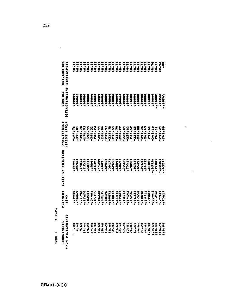
222
• L •
-Col--III .... 110"'" • -III 111111 ........ ... ... • • --Col -• ""
IIJ
••••••••••••••••••••••• NN~ •••••••••••••••••••••••• N • ••••••••••••••••••••••••• N •••••••••••••••••••••••••• •••••••••••••••••••••••••• • • • • • • • • • • • • • • • • • • • • • • • • • • I ,
._N.-•.. ~.~~.N.~-N_~N .• ~~~
.e_~~.N~N.N~.NN_N~~._~N .• _
.~e~-~~N.~-.~.~~N~ .. -.-.~N ••• ~.~ •• ~N~N~CN~~-~~. ___ ~~ •• _N~~ ••• ~~ ••• ___ •••••• N~. • • • • • • • • • • • • • • • • • • • • • • • • • • . I I I I
· .~N.-~~C~.N~.~~N.~.C_~~C._ • .~.~ •• _~_N~ __ ~_.~~~.~~~.~_ M- .~-.r..~N __ .... __ N~.~-~.N .• EZ •• _N~.~._C~._N~.~.-~ •• N~.~ _- ••••••••••• _______ ~ __ NNNNN
» - •••••••••••••••••••••••••• • 1111I11111111111111111111 E
.. ...
II
.. ;I)-... = _c ...... 2111 -::I ::I'" • a; Q .E :..I.
;1:. ..
•••••••••••••••••••••••••• .~ •• N.r •• N.r •• ~.~ •• N.~ •• N. • • • • • • • • • • • • • • • • • • • • • • • • • • .~.~.~~~~.N-N~~.-._~.r..~.
--NN~~ .. ~~ .• --==~~ •• -_N .................
RR401-3/CC
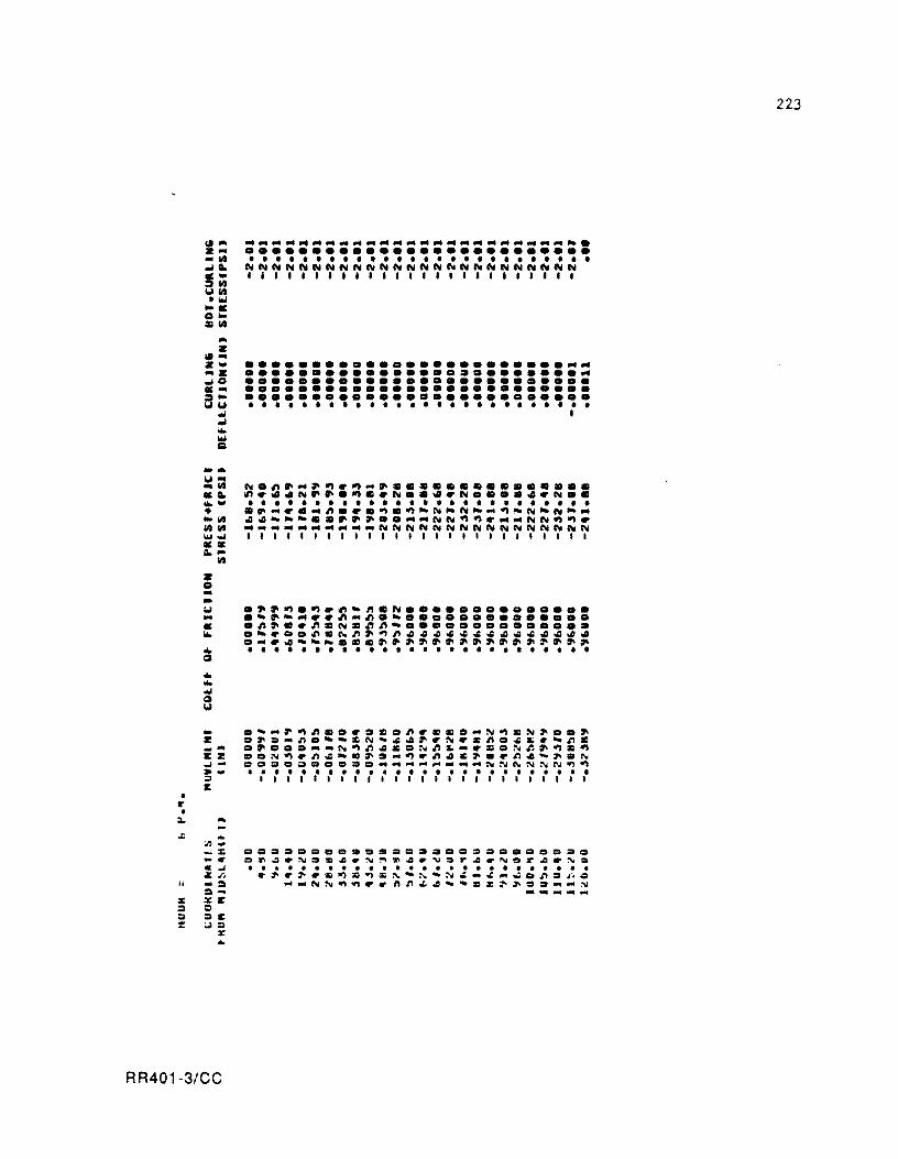
• .. • ;.
or;
II
% :I :I :::
... z
"'z ... -z _0 .... a~ ... ... ...
10loi Q
.-1.1-_III .... ...... • _III 111111 ........ -....
III
Z o -... 1.1 ... • ... ... CI
... ... ... CI 1.1
....•................... -. •••••••••••••••••••••••••• • • • • • • • • • • • • • • • • • • • • • • • • • • NNNNNNNNNNNNNNNNNNNNNNNNN , .. , , .. , .. ,." ..... , .. , ..
•••••••••••••••••••••••••• •••••••••••••••••••••••••• •••••••••••••••••••••••••• •••••••••••••••••••••••••• •••••••••••••••••••••••••• • • • • • • • • • • • • • • • • • • • • • • • • • • •
- .'-~~nzo~.zon~~z._~~~~~oo~ z D~=-n.'-:r:;N'~~~'N~:r:;n •• c.-n:r:; ~ ... D~ •• D--N~n~~DNn~-'~DNr.~~~~ cz D.N~'n~-z~ .... ~.n~&~.'n~-~.N oJ .... =D.~ ••••• ___ ...... ___ NNNNNN~~ » - •••••••••••••••••••••••••• :;:I 11111111.1",1"', ••• , •• 1 C
...
... ;n ... ... :r:; -. CoJ z. .. ... :1 :1-%1:' :I :Ie :..1::1
:II: ..
•• D •••••• DDD •••••••••••••• a~~.~D~~.~~~~.~Dr~.~er~.~a
• ••••••••••••••••••••••••• .~.~'~~D~D~-~'N~_~~~on.~ •
... _NN~~ •• nn~~'~ZC~~.2 ...... ~ -........ ...
RR401-3/CC
223
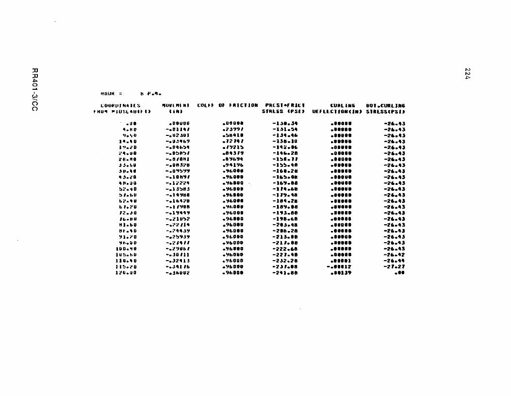
:n N
:n N
~ .J:'-
0 ...... I ItUUN = tt ...... w --0 \,;OUlW' NIlIlS "OVUUNI COlft Ut flUCIION PItt:.SI.fRU.:: I t:UItLINIi tiOl.CURLUIIi 0
t HU" "lUSLIIUU I' Uf., SIItl5S CPSI J U£fLLCIIUNCINJ SIR[SSCPSIJ
.110 .OOUUO .0008' -1.1 •• "" •••••• -2 .... " II." 0 -.0 ... , .2.t991 -IU.5 .. •••••• -2 •• '" 'J.o,. -.U2.s.1 .~II'I' -I" ...... •••••• -2 .... "
111.'0 -.11",41>9 .1214 , -U8.1O •••••• -2 .... .., .-'.20 -.O.,,~, • I"21~ -I'~.' • ., .... -2 .... .., "'41.UO -.O!J"~I ... "" -1 ••• 2. • ••••• -2 .... .., ~tI."O -.01'''1 .8'16" -1~'.1' •••••• -2 .... .., Jj.bU -.OtUOI''' ."'1'1. -I~~.'. • ••••• -2 .... .., J II.' 0 -.O'l!J"I9 .9".8. -16 •• 2. •••••• -2 .... .., , .t.lO -.101t." .96 ••• -l.~.'. • ••••• -26 ... ..,
"".illI -.10:'22" • '1 ... 0. -I.' ••• • ••••• -2 .... .., ~ ... i' -.I.s!JII.s .'1foOOI -114.611 •••••• -2 .... .., ~1.bU -.1'''1110 .91>.1. -I".'. •••••• -26 ... .., 1»l!'.4. -.11>"01''' .'1".8. -1 ••• 2. • ••••• -2 .... .., b ,.?U -.""1111 .'1" •• 0 -1.'1.'8 •••••• -26."3 '2.dO -.1.,4"9 • .,foO.O -1"".88 •••••• -2 .... .1 Ib.IfU -.llU~2 .9"". -I' •••• • ••••• -26 ... .., 1t1.e.0 -.~2Il' .'160" -;11.1 ••• • ••••• -26."3 IH·.'O - .... 4.""1 .'1"0'. -2' •• 2. ..0 ••• -2 .... .., "I1.i'0 -.2!J'IJ9 .,e.'IU -213.'. • ••••• -26."" .,11-.110 -.'2 "'" .'11>00' -21 .... •••••• -26.''''
lUO.'tU -.2"1 .... , • .,1> ••• -222.6 • •••••• -2 .... 3 IU!:l.hO - • .so III • "IbOOI -221.' • •••••• -1!' •• 42 110.' 0 -."2"ll • "1600' -2"2.2. .... 11 -26 ..... II !:I.?O -.",41 II> ."11>00' -2.1 , ••• - •• '112 -21.21 IlII.IID - • .sl>UU~ • 9b'.' -2'1 ••• •• 11..,9 •••
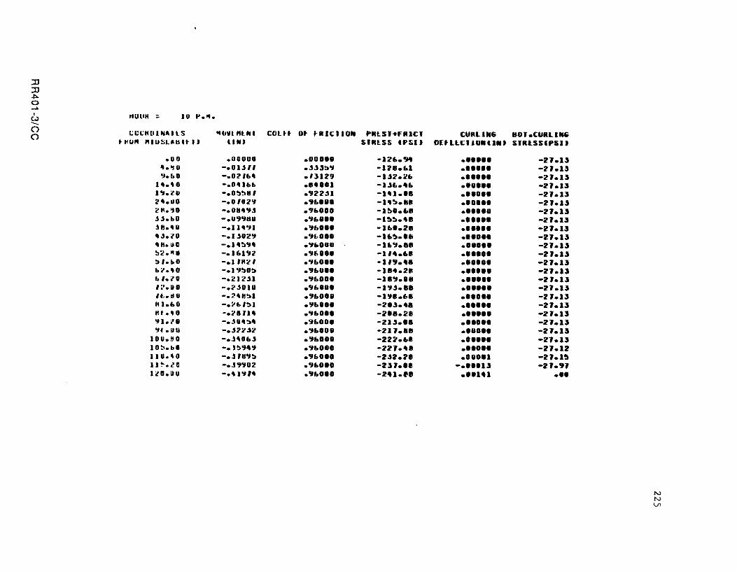
JJ JJ ~ a ..... . "UlIH ~ IU t'.". W ........ () c.:CCHlI1N_llS .. OWl "lNI COltt ()
~HU" "IUSL.b'~I) UfO
.00 .OOOUO
'.'1' -.01"" ";I.t.. -.Ol' ...
I •••• -.0 'IM, 1"I.l' -.O~~'U
l'.IIO -.0102'1 211.':10 -.0 .. ".,,, J".I>O -.U".,III J8.1II0 -.II.OJI " ".l 0 -.1"02':1
""."0 -.I'!!:I"I" !:l2."U -.161'12 :".1>0 -.1 '":t' 1>2.'0 -.1"~03 b '.lO -.212.s1 ':'.11 -.2"011 If, • ., , -.7.4831 81 .... 0 -.:-LI'!JI lit •• O ·.28 J1. 'I1.i'0 - • .s , ":10' 'If.UU -."22.s2 IOU.~O -•. H'"'' 10~.bO -.'!:l"" 110.'0 -• .s JII"I'!J 11 ~ .. ! 0 -.J"'J02 IlI.IO -.41'114
ot fRICllON PRlSI.fRICI SiflESS lPsn
.00.01 -12".CJ4
.""33'1 -1211."1
.'3129 -1.52.o.!"
... 4 •• 1 -1.5 .......
.922"1 -IAU.'" • 9 .. 181 -1'3 ••• .9" •• 0 -1!!:I'.68 .'1 .. 8 •• -I~!!:I.'"
.OJ .. '.' -1 .... 28
.OJl> ••• -U,~.'. • OJ"'OO -16., .... .'161" -1, •• 6. • ., ..... 1 -119 ••• • '1 .. 0" -1 .. 4.2. . ., ...... -111., •• 11
.'1"'.' -1"1.5."0
.9 .... 1 -I" ..... • ., ... 10. -2'.5.'. . ., ...... -2'8.2. • 96 ••• -21.5.' • • ., ... 01 -211.8 .. • ., .... 1 -222.68 ."1 ..... -221.'8 .9 ..... , -2"2.211 .9 ... 0 •• -231.'8 .9 ..... -241.11
CURLIN6 (lOI.CURLIN6 O[tlL~IIU.II.J SIR~SSCPSIJ
•••••• -:1l.13 •••••• -21.13 •••••• -21.1.1 •• 1 ••• -2J.U •••••• -2J.I.I •••••• -2J.l.1 ••••• 8 -2J.l.1
• ••••• -2J.l.1
•••••• -2J.U
• ••••• -21.1.1 •••••• -2J.I.I
•••••• -2J.I.I •••••• -2J.l.1
•••••• -2J.13
• ••••• -21.1.1 •••••• -21.1.1
•••••• -21.1.1
•••••• -21.1.1
• ••••• -21.1'
•••••• -2J.I.I .'8." -21.1.1
•••••• -2J.U
•••••• -21.12 •• 10.1 -2J.15
-."n3 -2J.9J ."1.1 •••
N N VI
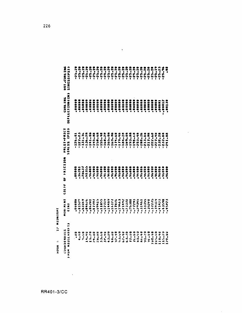
226
~-.... ..... ..... .-:114 1.114 . ., •• c:I. =14 ... • ..... . -....
... c:I .... :1-1.11.1 ... ... ... .,
Q
--1.1-... 14 ... ...... • ... 1414 ........ • ¥ a.-
;12
• c:I ... -1.1 ... • ... ... c:I
... ... ... g w
-z ...... EZ --:: .. -;II :I It
Z =-E ... :\I ... ... ;12 ...
.... : _c c~ Z~
" -0 =--:r:: .x.C !) :I !:) :II: :: :..1:1
:L ...
RR401-3/CC
......................• ~~ . ~~~~~~~~~~~~NNNNNNNNNN ... ~ •• • • • • • • • • • • • • • • • • • • • • • • • • • • ~~~~~~~~~~~~~~~~~~~~~A~~~ N~~NNN~NNNNN~~N~N~~~NN~N~ 1"" •••••• ' •••• '1 •••• 111
....................... -~ . ........................... ~ ............................ •••••••••••••••••••••••••• •••••••••••••••••••••••••• • • • • • • • • • • • • • • • • • • • • • • • • • • I
.~~4 ... ~~~~~~~~~~.~~-~cn~~.~
.~.~.~-~ .... ~~~~~.~~ .. ~-~-~~~
.~.4N~~.-~_»~~~~~~~~NN~~n~ . -~~4-~ ... ~~ .. -~-~n-~-~n~~-~n •••••• ~ ...... - __ ... N~~~N~~~~~ ••• • ••••••••••••••••••••••••• 111111111"111'1"111'11'
• ••••••••••••••••••••••• = • ~~~.:\IO~~.N3~~.~O»~.~O~~.~~
• • • • • • • • • • • • • • • • •••••••••• .~.~.~~~~:r::~~~~Nw ....... _.no~C __ NN~~~.~n44-~~Z~~.= __ N ,... -_ .....
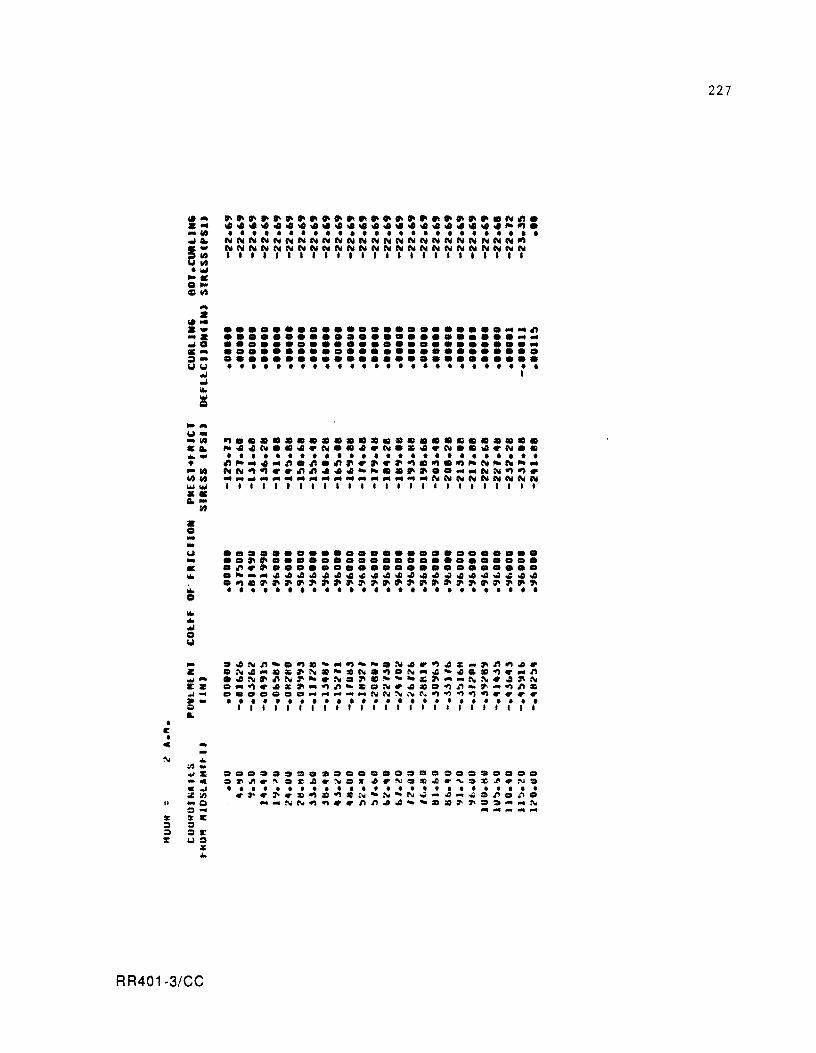
• I: •
... • \(f" ... -Z .0 &-=-101101 -• ... ~
....... 101-
-'" &Ao ..... • -CIt CIt CIt ...,1Ii •• Ao-
Z o -.. "" .. • ..
CIt
~~~~~~~~ •••••••• ~ •••••• N~ • ....................... ~~. • • • • • • • • • • • • • • • • • • • • • • • • • • NNNNNNNNNNNNNNNNNNNNNNNN~ NNNNNNNNNNNNNNNNNNNNNNNNN """ ••• 1,1,1.",1"""
........................... ~ ............................ ........................... •••••••••••••••••••••••••• •••••••••••••••••••••••••• • • • • • • • • • • • • • • • • • • • • • • • • • • I
• ••••••••••••••••••••••••• .. ~ •...................... .~ .•...................... .~-.~~~~~~~~ ...... ~ .. ~~~ .. .~ .. ~~ .. ~~.~ ............. . • • • • • • • • • • • • • • • • • • • • • • • • • •
_ .. ~~~.~.-.~~~.N.r~~~_.~~.r Z .~~ .• ~.~.~~N.~.N.~-~.~~ .. ~ * ..... ~.~N.~.N .• ~--~~.·~N~.~.N I:Z •• ~ •• c._~~_ .. ~r ... ~~_.~~~. ~_ e •• e •• e _____ NN~~~~~~~~rrrr · - ......................... . Q 1111111111111111111111111 L
C ...
II
.. "'..,. ·c c~ il'.iII ... a 0-!irE Q QI: UO
¥
""
RR401-3/CC
•••••••••••••••••••••••••• ~~~r~.~.r~=~~r~ •• ~r~ •• ~rN. • ••••••••••••••••••••••••• r.r.r.~»~ZN-~-N~~~~ •• ~.~.
-_NN~~rr~~.~ __ .» •• =._~~ .......... -
227
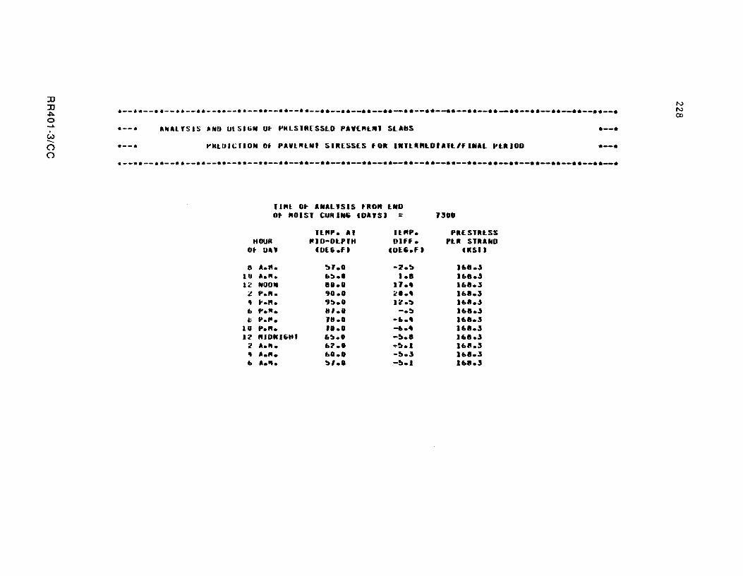
::IJ ::IJ ~ o ..... . U)
---o o
.--•• --•. -- .. --•• --.• --•. --•• --•• --•• --•• __ •• __ •• __ •• __ •• --•• --e.--•• -_ •• __ •• __ •• __ •• __ •• __ •• __ •
.--. ANAl'SIS liND ut SUiN Of f'KLSlItESSLD PAtOIL'" SLABS .--.
.--e ~KLOI~IIUN Ot PAVt"LNI SIRESSES tOR 1"'tl"LDIAlt/fl"Al I'tRIOO .--. e--.• --•• --•• --•• --•• --•• --•• --•• --•• --•• --•• --•• --•• --•• --•• --•• --•• --•• --•• --•• --•• -_ •• __ •• __ •
II"t 0. ANALYSIS tRO" tNO Ot "015' CURIN~ COAYS' = J300
It"P. AI IU'P. PRE SlRtSS "OUR IUD-DLPI" Dlff. PtR SlRAfilU
Ot DAY (DUhf) (UE~.F , USI)
8 A.ft. '!tl.O -2.'!t I .... .s lU a .... I.:'.' I.a U ••• .s 12 NOON 81.1 IJ •• 16 •• 3
2 ... ". '11.1 2 ••• 1 ••• 3 " ".N_ '1!».1 Il.'!t I .... .s I. ".". 111.1 -.'!t 1 .... 3 tJ P .... 18.0 -.... 1 .... 3
lU P .... 11.1 -.... 1 .... 3 12 "10"16"' 6~.' -!l.a U ••• .s
2 A .... L?I .,.!l.1 11011.3 " A .... .0.0 -!l • .s l.a.3 • A .... '!tl.1 -!l.1 168.3
N N co
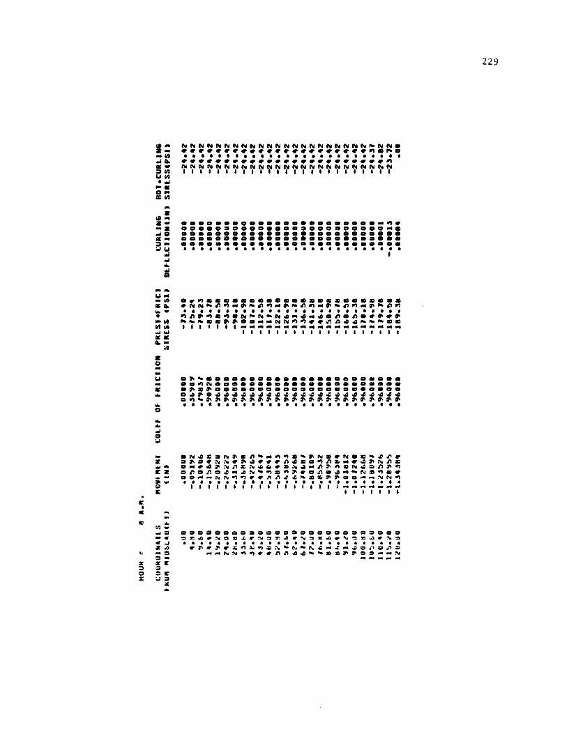
II: • C
II:
It
s ::I CI ::
• • ., ... . -... ..l0 ... ="'Cot ..
..l ... at _.
Cot • .. ;II ... ... -• -0 00 ""w •• .. -• o • -
",
~~NN~N~~N~~~~~~~~N~~~~~~~ • ...................... ".~. • • • • • • • • • • • • • • • • • • • • • • • • • • ........................ " ~~~~~~~~~~~~~~~~~~~~~~~~~ 1111.1111.11'1111111111' I
........................ ~ . •••••••••••••••••••••••••• •••••••••••••••••••••••••• •••••••••••••••••••••••••• •••••••••••••••••••••• 0 ••• • • • • • • • • • • • • • • • • • • • • • • • • • • I
.. " ...................... . . ~~~~" .. ~~" .. ~~" .. ~~".~~~" • • • • • • • • • • • • • • • • • • • • • • • • • • "~.~.~.~~~-~4.4.4.~.~ ..••• ~~- ••••••.. ~~"" •• ~~44~-~ •• 1111111 ...................................... ...
I I I I I I I I I I I I I I I I I I I
Cot .~- ••••••••••••••••••••••• .. .."~ ..................... . • •••••••••••••••••••••••••• ... .~~.~~4~~~~~~~~~~~~~~~~~~4 ."-.~.~~.~~~~~~~.~~~~~~~ ..
... . . . . . . . . . . . . . . . . . . . . . . . . . . o ... ... ..l o ;..\
_ .~~£.N~cn- ... "~.-~N •• ~ •• -~~. Z CI.D.~~ •• ~ ••• n~ •• "n~ •• ~.~nc ...,- ..... 4~~nc~~ ••• ~~.n~".~~Dn~" EZ .~.n.~ ... ~~-"."~ .. n.~ ... -~." .. • - ••• ~~N"~ •• nn~~_.~~~ •• _~~N~ » - •••••••••••••••••••••••••• g I I I I I I I I I I I I I I I I I I ~_~ ..... _. I: I I , , I I I
... 11\1-.... = -c fI:.J Z,I) ... 0 o sa: o o I!' UCI
:.: ...
.CI.D •••• CI •••• ClCI ••• ClCI •• = •••
.~~.N.».rN.r.~rN~»~.'~Z~.N=
• ••••••••••••••••••••••••• . ~.~._~~~.~-N-~~ ... ~_~.~.nD ... _NN~~ •• nn~~ __ .»~~ •• _ ... N ......... _ ...
229
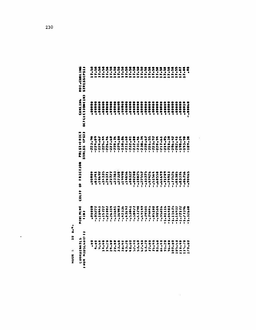
230
• E •
~- ...................... ~- .. a· ~~~~~~~~~~~~~~~~~~~~~~~ ••• _0 ••••••••••••••••••••••••••
~~ ------------------------.- ------------------------.:tilt ~0 ."'" •• D_ Cllt -a ;/I. a- •••••••••••••••••••••••••• ·a •••••••••••••••••••••••• -. ~D •••••••••••••••••••••••••• •• •••••••••••••••••••••••••• .:a~ •••••••••••••••••••••••••• ~ ~ ......................... .
"'" I ~ ... "'" c:a
~-~ ... _lit .~
... -• .. 0 00 ........ •• ~ .. • D • -~ ... • •
o
_ .N_N~~_~~~_~.~_~.~~.~~NN •• & .~~N._~~~~~~~~.~~D ....... ~~~~ . ........ • N~~.~.~~.D~~ ... ~~.~~ ... ~.~-~. 1:& .n.n_._.N-~.~~~~~.n_ ..... N~N w'" •• __ NN~~ •• n~~~~~~~~D. __ N~~ · - ......................... . !OJ 111111111111111111 .................. -I: 11I1I1I
C ....
:s ... - 11.1-.... :1: ... . ~ .i/) II ... :a :a ... iii: 1Ii:':: ::I Q :;, ::I.:: :: :.J:;'
:II: ...
•••••••••••••••••••••••••• .v •• N.m •• ~.E •• NO~ •• N.C~.~ • • • • • • • • ••••••••••••••••••• ~~.~~~~~~~N~N~N .... _ .... o~.ro ...... NN~~ •• ~~ •• ~~c.~~o ....... ~ ... ........ ....
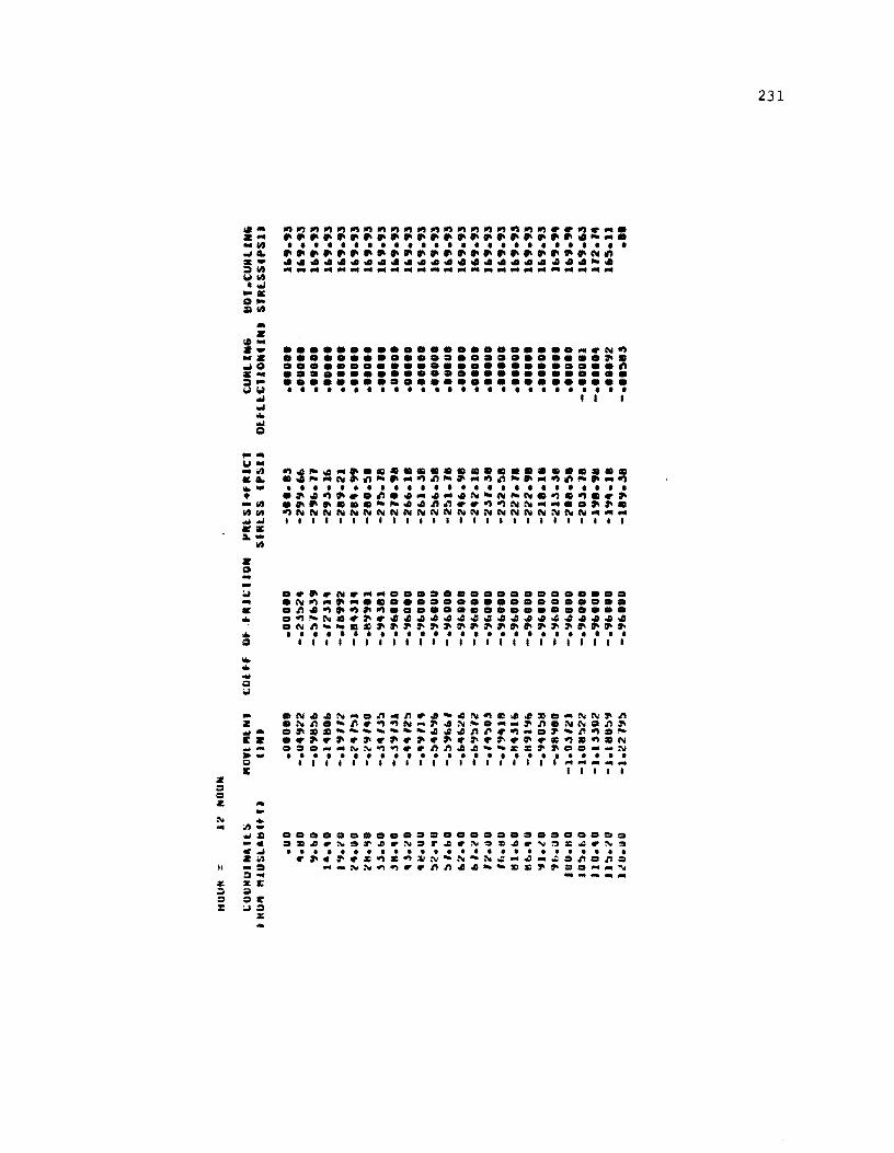
z = Q
_. u-~ C~ ~w • -~ ~~ ~~ C&
~-~
Z _
"
• ~. ~. -c C~ Z~ •• =SC ~
=~ ~=
%
•
•••••••••••••••••••••••• N~ ........................ ~ . ......................... ~ •••••••••••••••••••••••••• •••••••••••••••••••••••••• • • • • • • • • • • • • • • • • • • • • • • • • • • I I I
..•. N.-- ...••............. . N~_._.C ................. . • n4~.~~~ •••••••••••••••••• a~~N •• ~.444444444444444444 aN~~_ •• ~~~~~~ •• ~~ ••• ~~ •• ~~ • • • • • • • • • • • • • • • • • • • • • • • • • • 1,." •• ,1'1","11'1"",
aa.a.OO.Do •• a •••• a.o.aoa •• . ~~.~.r~.N.r~.N.~~.~~~~.~. • • • • • • • • • • • • • • • • • • • • • • • • • • .~.~ •• ~=~~~~N~N~-4_~.nan. __ ~~~~ •• nn.4 __ •• ~~ •• __ ~
-.~--
231
HOUM = it t' ....
I;UOkUINUlS .. uVl"UIl tH6" "lU~L.lln n UN.
• 110 .OOOUO ".ISO -.0 .... 0 '1.LU -.U"2"1
I •••• -.I.i"~ , 1':t.i!'U -.1111,," ..... Ou -.1.i"jl'j /t1l.HI -.jl80.i. ".i.bU -."2 Ij, "11. III U -.-',.,,:, 4".orO -."21~1
48.UU -.'LII~l
:':.".tI. -.~1~4,s
:, ,.fa. -.~b22~
"2 •• U -."089" fa,.tU - ... ~!)" ,
'2.'" -.'U"" ",.1:1. -. '.ftl" II.fa. -.,.,"U:» 11 .... 0 -.8"':f"fa .,1.itO -."e!»4" ',It,.UO -.':f-'U .. 4
100.110 -."'''U1 JII~."U -1.0lD". l1U •• 0 -1.Ob!»"~ 11 ~ .... -1.118.., lilO.UU -hl~'.i'
COlft Of tRlctlON PlllS'.f 'Uti S'"lSS CPSI.
.00000 -.5'''.~' -.,s.111 -.t07.1I1 -.,""'., -2".1" -.I~II':' -2' .... ~ - .,,s.51' -2".111 -.9L'" -211~. 3e -.9LI •• -2 ••• ~e -.'1 .. 1 •• ' -2''!I.'' -.9L.I. -2' •• '1 -.9" •• ' -2 ••• 1. -. ., .. , .. -2.1 • .5. -.9L ••• -2:. •• ~. - • .,L." -2'!11. II -.' .... 0 -2 ••• 98 -.'''0 •• -2.2.1. -. .., ..... -2.t1.311 -.9".'0 -2.52.~t
-.':fL"O -22'." - • ., .... 0 -222." -.9b"0 -2111.18 -• .., ... 8. -21.5.311 -.9LO •• -2'1.~" -.'1 .. 1 •• -2 • .t." -.':fLO.' -1'''.'1 -.9"'.0 -1'4.111 -.':fL'" -11'.3"
CURtl.G ltOI.CURUN .. DEflLCIIOIU IN' SIRESSIPSI.
•••• 0 • 1".23 ••• U •• 1".23 •••••• 1".23 • ••••• 1".2.5 •••••• 1".2.5
•••••• 1".23
•••••• 1".23 .1 •••• 1".2'3
•••••• 1".23 ...... 1".2",
• ••••• 1".23 ••••• 0 1".2.5
•••••• 1".23
•••••• 1".23 .0 •••• 1".23
•••••• 1".23 • ••••• 1".23
•••••• 1".2'"
•••••• 1".23
•••••• 1".23 •• 0 ••• 1".2 ..
•••••• 1'9.2 .. - •••• 01 1'8.1111 - •••• O~ 2'2.~2 •• 11 ... 1'!13.~1 -........ .00
N W N
IiOUH = 4 ... ".
(;OOMttINallS "OWl "un COlff OF fRiCIiON ttlO" "IU!;L_ttU·I' urn
• UO .OOOUU .00.00 4.!l0 -.0"'11 -." .. OJO, " ... U -.o.,oo~ -.,.,8.s.
1 ••• 0 -.1":''' , -.'100J2' 1"1.10 -.1110 ... -.'1 ... 0. "'.UO -.Z2 .. ll - ..... 00. il 11.11 U -.ZI1 .. '1 - • ., .. 00. ) l. bU -.ll'll - • ., .. 00. -'H •• O -.-'b2"~ -.""000 • l.ilO -.'011:''' - ..... 00. .8.UO -.':'414l - • ., .. 00. ~".1t0 -.'''''~'1 - ..... 00. !J ,. b U -.:"''1' - • ., .. 000 b .... O -.~'101" - • ., .. 00. b'.IO -.b.s:'?l - • ., .. 00. ,,,,.u 0 -."11010 - • ., .. 000 Ib."O -.'''''''0 -.""000 IH.bO -. 't.'1"0 -.'1"000 11 .... 0 -.III"~'1 -.'1"'00 '11.1.'0 -.II~'''!J -." .. 000 .,L.UU -.'101''1 -.""'00
1UU.IIU - .... :.IU -.'1"0.0 IU~."O -.'18"'. - • ., .. 000 1IU •• O -1.0"1"., -.'1 ... 0. 11~.i.'0 -I.U ,.:,. -.'1"000 1Z0.UO -1.11 Ill., - • ., .. 000
PRlSI4fltlCI CURLIN6 SlItlSS CPSU DULLCIIONUN'
-3.:'.3 .. ••• 000 -3.3.:'2 .00000 -2"".:''' .0110110 -2., •• .,8 .OUOOO -2.,0.18 •• 00 •• -28:'. "8 •• 000. -2110.!t1l •• 000. -21:'.'8 • 00.00 -2' •• 0J1I •• UO •• -2 ..... 1. ••• 00. -2"1.311 • 0000. -2:. ... :.8 ••• 0 •• -2:'1.18 •••• 00 -2 .... 1J8 •••• 0. -2.2.111 •• 0 ••• -2.s'.38 • 0 •••• -2.s2.:'8 ••• 00. -221.111 • UUOO' -222."~ • 0 •• " -218.111 •••• 0. -213.38 •• 0.0. -2' •• :'. ••• 00. -20.s.'11 • ••••• -198.'111 - ••••• 3 -1'14.111 •• '0 .... -111'1.311 - •••• 1.,
BOI.CURLlN6 SUESSCPSI)
122.0. 122 ••• 122 ••• 122 ••• 122.0. 122.0. 122 ••• 122 ••• 122 ••• 122.' • 122 ••• 122 ••• 122 ••• 122 ••• 122 ••• 122 ••• 122.' • 122 ••• 122 ••• 122 ••• 122 ••• 122 ••• 121 ••• 124.09 11 ••• 1
.0.
N W W
234
~
a ~-z- •••••••••••••••••••••••• ~~ _a .0 ••••• 0 •••••••• 0 •••• 0.0._ ~o •••••••••••••••••••••••••• . - ......................... . ~ ............•........•..... ~ ~ ......................... . ~ I ~ ~
! -~--~ r4N_~~.~~~.~~N~_~N~_.~~N •• • ~ •• -~N-~ •• -~~N •• N~.-~r~~~.~ ~w •••••••••••••••••••••••••• • r •• ~N_~. __ •• _ •• N. __ r.N ••• ~ .~ ~~~~~~ ••••• r.r~~~~ ••• -- •••
"~ -------------------------~.w I I I I I I I I I I I I I I I I I • I I I I I I I I •• ~-~
• ~~ . _c c~ z~
-~ ~st ~ DC ~o
& •
•• O.OOODODDD.OODOD •• ODOD.D • r~r'D~~.ND~~.N~~~.~De~.~. • • • • • • • • • • • • • • • • • • • • • • • • • • r~r~r=~~~=~-N-N._~_~D~O~O __ NN~~rr~~.~-_ •• ~~DO __ N
--"--
• I: •
.... .... "'111 ..... .... :1111 WIO .... -. D_ :Dill
... • .... .... .... .... .... :I. WW ... ... ..
! .... W... ;It ."" .... • _10 10111 .;.1.;.1 11: • ... • D ... • .., ... II: •
... ..
.;.I o W
10
.. ...
II
z ::I :s ::
............................ " . ~~~~~~~~~~~~~~~~~~~~~~"~~ . • • • • • • • • • • • • • • • • • • • • • • • • • • NNNNNNNNNNNNNNNNNNNNNNN" • ... ., ••....... .,., .... ., .... ., III 1111111'1 IIII IIII
••••••••••••••••••••••• N •• ........................ " ... ••••••••••••••••••••••••• N •••••••••••••••••••••••••• •••••••••••••••••••••••••• • • • • • • • • • • • • • • • • • • • • • • • • • • I
:~~~:==:~::~:~~~=,=~~=:~~~ • • • • • • • • • • • • • • • • • • • • • • • • • • ~ ••• "- ..... "-N .......... ~.~ ••••• ............. NN"" •• ~~ •• --~ •• I I I I I ........................................................ ...
I t I I I I I I I I I I I I I I I I I I
•••••••••••••••••••••••••• • C~.~ •• 4.N.C~.'.C~.N.C~.~. • ••••••••••••••••••••••••• • ~.~._"C~CN-~-~ __ ~_4.r..r. __ NN~~ •• na~~ __ CC.~ •• __ ~
...... ---
235
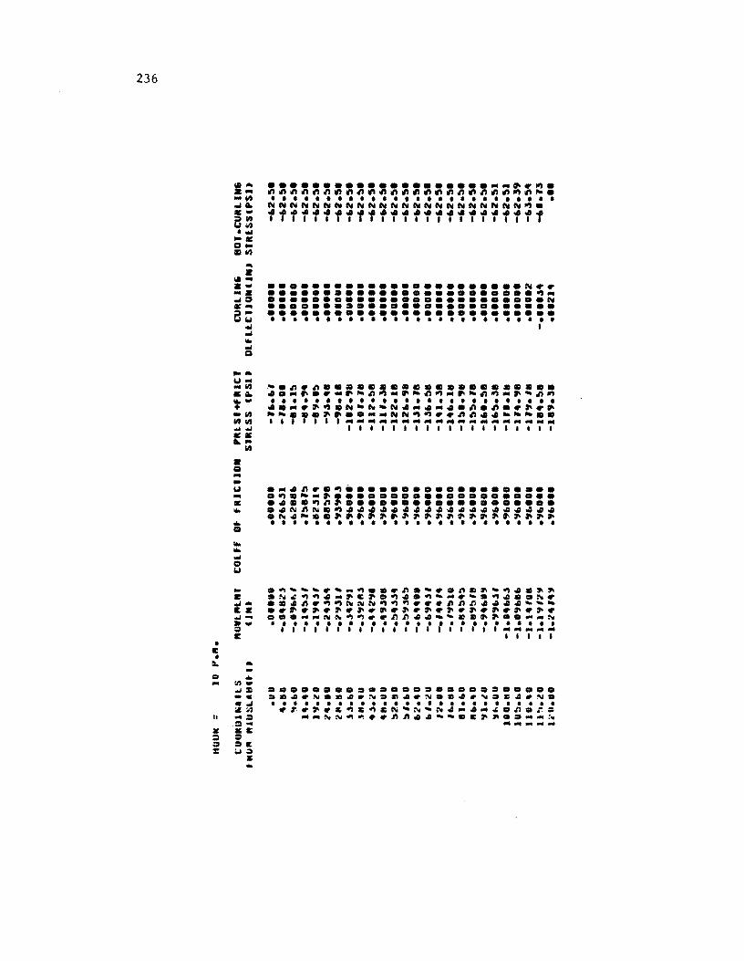
236
• I: •
... a
\la-a ~" c-e:::
001 ~ ... "" Q
...... .., ... -"" &a. ~• .. "" ""til ...,.., c • ...... • " ... .. .., -c ...
til
:t. ...
III ... .... tII_ ...,=
-c ..... "'., II ... :1 :I ..
Z .1: :I :I :I :lit :: ;.1:'1
a: ...
.......................... ~.~. ~~~~~~~~~~~~~~~~~~~~~~~~-. • • • • • • • • • • • • • • • • • • • • • • • • • • NNNNNNNNNNNNNNNNNNNNNNN~ • ••••••••••••••••••••••••• ••••••••• 1 •••••••••••••••
••••••••••••••••••••••• N •• ........................ ~ ... ••••••••••••••••••••••••• N •••••••••••••••••••••••••• •••••••••••••••••••••••••• • • • • • • • • • • • • • • • • • • • • • • • • • • •
•••••••••••••••••••••••••• .. ~.N .. ~.~.~4.N.e4.~.E~.~. • ••••••••••••••••••••••••• .~.~.~~I:~C~-~-~4-4 ... ~.n.r=
-_~N~~ .. ~~.4--.C~~ ........ ~ -..... ...
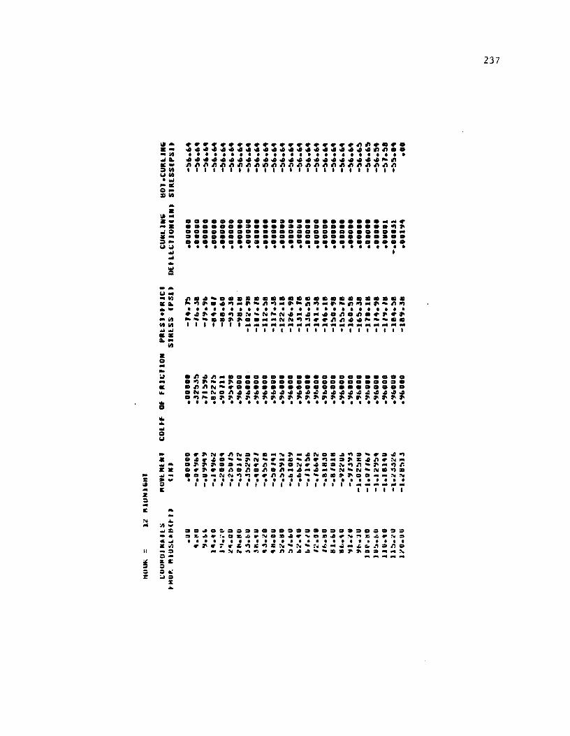
-z: III .. Z :. ... E
... • III" a • ...
~:t ... ~ .. ~ ...
"'" ... .. ~
-... ~ ... .. ~ 11:110. •• • _lit lit lit ..t..t 11:. 110._
• g ... .. u ... IE ...
... a
lit
...... ell! ..t.... g ..
... .. :It ... ..t:l:: -... C..l .. :It -~ :::s-& .. :. :::sa: ;..)::1
% ..
~~~~~~~~~~~~~~~~~ ... ~~ .... ...................... ~~ .. • • • • • • • • • • • • • • • • • • • • • • • • • • ....................... ~~ ~~~~~~~nn~~nnnnnn~n~~~~~n lllll •••• llllllllll.lllll
•••••••••••••••••••••••••• ........................ ~~ •••••••••••••••••••••••••• •••••••••••••••••••••••••• •••••••••••••••••••••••••• • • • • • • • • • • • • • • • • • • • • • • • • • • l
n.4- •••••••••••••••••••••• -~~ •• ~ ... ~-n~.~~~~-~~~~.~-n~ • • • • • • • • • • • • • • • • • • • • • • • • • • ~4~~.~.~~N-N.·4· •• ~.~.~~.~ --- •• ~ ••••• NN~~~~~n •• ___ •• I l I I I I I .................... .
I1I11I1I11111111111
.r~Nr~N.~ .... ~~ .. 4ND.4~.-r.4~ D4r4D--~N-~ .... ~n~~ .... ~.4~r~_ .~~ ..... Nr~~~.Nr4 •• N~~-.-~r. • r.~.~.~.~.~.4 •• -~N-N-N.~. .= ... NN~~~.~~44-~ •• ~~ .... _NN • ••••••••••••••••••••••••• 1 I I 1 1 I 1 I I 1 I 1 I I I 1 I I 1 ... --- ......
Illll,
•• ~=~ •••••••••••••••••••• = ~~~.~.&~.N •• 4r~ •• 4.~~Z~.N~ • • • • • • • • • • • • • • • • • • • • • • • • • • r.r~r.~C~.N-N-N~ ... ~_~~~.n=
--NN~~rrnn44-- •• ~ ........ N ..............
237
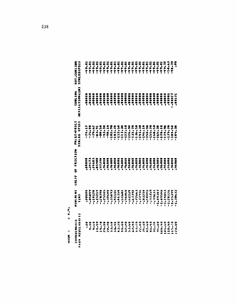
238
• ... •
lit ... a .. .. lit ..... .... ;:'1It Wilt .... -. CIllO :lilt
... a ....
a ... .... ... 0 .... ;:,w,", ... ... ...
l! .... W" ... 1It ... ... -• -lit lit lit ~"" CC ... • CI .. ... W .. • ... ... CI
... ... ... CI W
-
lit
• ....... It • -Ow :I I:
c ...
II
... 1It_ "". _c C ... Z:.1 ... ~ :tSI: = :r :.1:1
..s. ...
......................... -... ........................ ~............................ •••••••••••••••••••••••••• •••••••••••••••••••••••••• • ••••••••••••••••••••••••• I
-.N ........................ . .... 4~~~ ... ~-~~ ... ~-~~ .. ~-~~ .. ~-~~ • • • • • • • • • • • • • • • • • • • • • • • • • • .~~~.~.N-N-N4 ... 4 ... 4.~.~ •• ~.~ --- •• ~~ ........ NN~~ •• ~~44--- •• I I I I I I I ...................................................... ...
II1III1111111111111
.~~ ...................... . . -.. ~ .......•..•.....•.... • ... 4~~ ••••••••••••••••••••• ••• ~~~44444~44~4~4~~44~~~4 .~-.~~~~~~pp~~~~~~~~~~~~~~ • • • • • • • • • • • • • • • • • • • • • • • • • •
.~.~.n.~~.N •• N~4.n~~-.~~~N •• N ..... &~ ... n.~N~4~-~n~.&nN~-
..... N~~~& ... ~~ .... ~4~N.-.~~.-~~ • ~.~.~.~ ... ~ ... 4N-N-~.~~.~ •• n. ........ NN~~ •• n~~~--.~~~ .. -NN~ • • • • • • • • • • • • • • • • • • • • • • • • • • I I I I I I I I I I I I I I I I I I I ............... ...
I I I I I I
••• c ••••••••••••••• : •••••• ~r~.'.z~.N.L~.~=~4.~sr~.~.
• ••••••••••••••••••••••••• .~.~.C~.~~N-N'N~~~ ... ~.n.n. -_NN~~ •• ~n~~ __ c.~~ ........ N .............
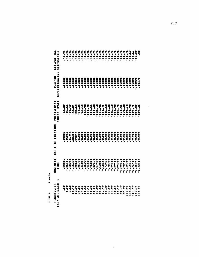
• ~
•
-~--~ SL ~• ~w WW M~ sa L-
• o --~ -S ~
-Z
w
~A
c • ;: = E
c -• ~~= _c
~~ Z~
-~ ~ac = =r u= ~
•
•••••••••••••••••••••• -N ••
______________________ •• N.
• • • • • • • • • • • • • • • • • • • • • • • • • • --- ____________________ N.
~~~~~~~~~~~~~~~~~~~~~~~~~ 1111I111111111I1I11111111
••••••••••••••••••••••• _m • •••••••••••••••••••••••• N_ :::::::::::::::::::::1:::: •••••••••••••••••••••••••• • • • • • • • • • • • • • • • • • • • • • • • • • • I
... --~N~.--N .. ~~_~n-.~ •• _N •• ~~-~~~---~-.~~~.~N~.Nnc_
.-~~~-.~~.-.c-.~-.--.--.-
.~.~.~-.-.~-Nc~m.~ .. n .• -.N •• __ NN~~r.n~ •• -_zc~ •• __ ~N~ • • • • • • • • • • • • • • • • • t • • • • • • t • 1 I I I I I I I I I I I I I I I I 1 ............... __
I I I I I I I
••••••••••••••••• 0 •••• 0 ••• .C.r~ .. ~.N •••• N .... N.~~.N. • • • • • • • • • • • • • • • • • • • • • • t • • • .~.~ .. ~.~c~-~-~w-.- .. ~.~. __ ~N~~ •• nn •• -·.~~~ •• _~~
~.---
239
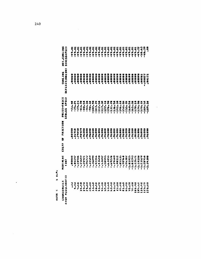
240
• II: •
... • l.a-.-z .jO . -a:
"" .j ... ~
...... 101--II) .Q. ... -• "'1/11 11)1/11
""'''"' •• Q.-
• • -... ... -• ...
1/11
C ...
II
:... C/I." ""':II -~ c""' z:n -0 =::I:1r. :I =Ir. :.1:1
:&. ...
....................... -~••••••• • •••••••••••••••• N~ ......................... -•••••••••••••••••••••••••• •••••••••••••••••••••••••• • • • • • • • • • • • • • • • • • • • • • • • • • • 1
.~~ .............. ~ ..... ~ .. ~NN~~~-~~~~-~~~~_~~~~_~~~~
• • • • • • • • • • • • • • • • • • • • • • • • • • ~~~~.~.N~N~N._._ .. ~.~.~~~~ - __ •• ~~ •• __ NN~~~~~~ •• ~~_ •• I 1111 II __________________ _
111111111111111.111
~'~ ••• == •••• D.~ ••• ~ ••• =.=~ ~Z4.~.~4.~.e4.~.~4.~.~~.N. • • • • • • • • • • • • • • • • • • • • • • • • • • ~~~~.~~:II~~N-N'~_-w_ .. ~.r.. __ NN~~ •• ~~~4-- •• ~~~D __ N ............

241
• • • I I I I I I • • • • I I • • I I • • I I • • I I ::I • Q • .. I • I ~
• a. • 14::1 • • 14. I ... I ~C'" I C I .... ............. • • • ..... 14 • • • • • • • • • • • • • .. • 1414 • ••• e.e ..... c. I 110 I ... • • ••••••••••• I .... I •• ~~~~~~~~~~~ ... • ~ • • a. ... • .. • • a. I C I .., I ... I .. • Q • • ~ • I C I ... I • I • '11. • 14 ... • a. 110 • •• ~.~.,eN.., ... .,~ • • - • 11;11011 • • • • • • • • • • • • I C • I QII ~- ... N_ .... ""I.., ••••• I ... ... I • ... == I ... ... I I I I I I • 14 • ~ • • • • ... I ... Q I CI4 I • • I Q .. • ... • .c • C 14 • IIoQ
• ... ... I • • • 14 I 14 ... : • C 14 • -II c .... • L ~ • 14. a. ... • •• 0 •• 00 •• 0. I II: I .. - .... • • • • • • • • • • • • • • = I .... LOCO ,,~ •• ".4.,N ... O"" • ... 14 • CQ Elooi .",It • .tI.tIItIl.tl.tl •• • 14 • ."" ... ::IQ I 14 • I C ....... I ~ • • E • :II: ~ ... 14 • .. • Q ...
• 14 oW :II -• ~ • .... ::/: • • c C 10 • L ::\0, ..... .. I .Q .. • •• t • • • •• • • • I
\?s ... :ll!C CCQCI:CCC=.IEC • Q iQ • • Q • • • • ... t • • • CCZ::\o,L::\o,La.I:CCC
I • • :a:: ...
• loll :II = C::::aNN •• C::::aNN ... • ... - ~ ... ... ... • :1'1
• ... :.I I : .. • = • :II ... I .. • I c ,. • • 14 I .. I :1'1 • ... • ... • C
• II! I • c • • • • I
• I • • • • • • • • • I
• I • I • • • •
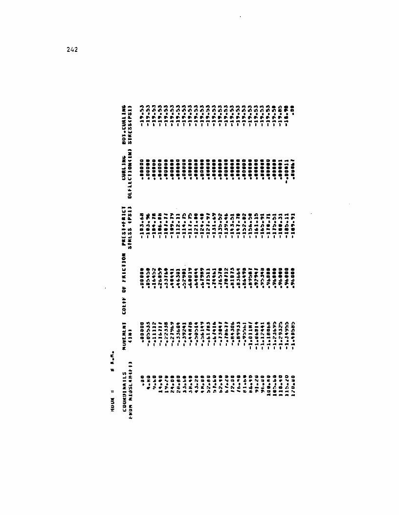
242
• E •
~U_ -~ .~ .• -~ ~~ ~~ •• ~-
• Q --U -• • • Q
• • ~ • U
~
C -
• ~~: -c C~ Z~
-~ ~. ~C ~ ~E u.
& •
....................... --~ •••••••••••••••••••••••••• •••••••••••••••••••••••••• •••••••••••••••••••••••••• •••••••••••••••••••••••••• • • • • • • • • • • • • • • • • • • • • • • • • • • •
:_::=t:~c::~~~#~=~~~;=~~=. • • • • • • • • • • • • • • • • • • • • • • • • • • ~~ .• -.N.--.--~~~-N.-~.~.n. ...... -__ NNN~~~ .. ~n •• ~~ ••• --------------------------1II1I1I1I1I1I1111111I III ••
•••••••••••••••••••••••••• .Z~.~ •• ~rN •••• N.~.rN.E.rN. • • • • • • • • • • • • • • • • • • • • • • • • • • .~.~.~~~~&N-N-N~~._~.~.~.
__ NN~~.r~~ •• --~=~~ .. __ N -.---
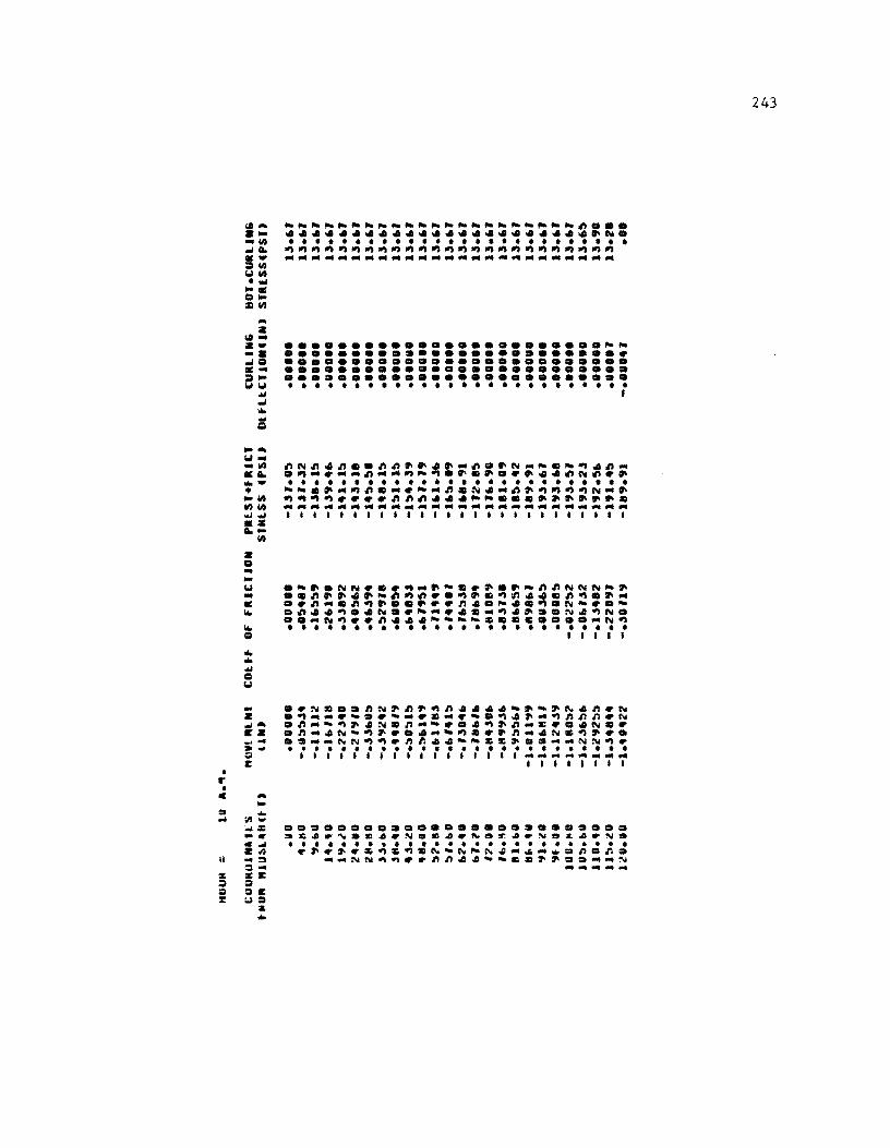
• r •
... Z
IotZ--. .I • ce-e:
"'" .I ... .w
= ~ ... W .. _ 1t.I
ceL . -• -en It.Ien ..J..J ce:.: Len z o --
~~~~~~~~~~~~~~~~~~~~~~~ ... ........................ N. • • • • • • • • • • • • • • • • • • • • • • • • • • ~~~~~~~~~~~~~~~~~~~~~~~~~
-------------------------
........................ ~~ ••••••••• a ••••••••••••••• ~ •••••••••••••••••••••••••• •••••••••••••••••••••••••• •••••••••••••••••••••••••• • • • • • • • • • • • • • • • • • • • • • • • • • • I
~N~.~ •• ~~ •••• _~ •• N .. ~._~.~ _ .~ .. ~--~ .. -~~~ ••••• ~ ••• ~N~~. • • • • • • • • • • • • • • • • • • • • • • • • • • -- .... ~~.-~--~.N.-~.~~~~N-. ~~~~~~~~~~~ ... ~~ ......... . --- ....... ---.- ... --------111111111111111111111111 ••
W .-•. NN~.~~_.- ..••• _~~NNN_. .. ..~ .... -~~~~.~ .. ~~ ... ~~ .... ce .~~_.~~ •••• ~~~ •• _ •• ~.N_~._ ~ .~ •• ~ •• N.~~-~ •• "~ •••• N.~N •
•• _N~~~~ ••• -- __ z •• C •••• "N~ ~ . . . . . . . . . . . . . . . . . . . . . . . . . . • I 1 I I 1 ... ... "'" • w
c ... -... 1/1-.. :c -. .... z.n -~ 0-xc = oc uo
:I; ...
•••••••• a ••••••••••••••••• ~z •• '.m •• N~c •• ~Sr. •• ND~ •• N. • ••••••••••••••••••••••••• ..~ •• z~z~.~-~~~~ .. ~ .... n.r.. __ NN~~~.r.n •• --c.~ •• D .. _N -----
243
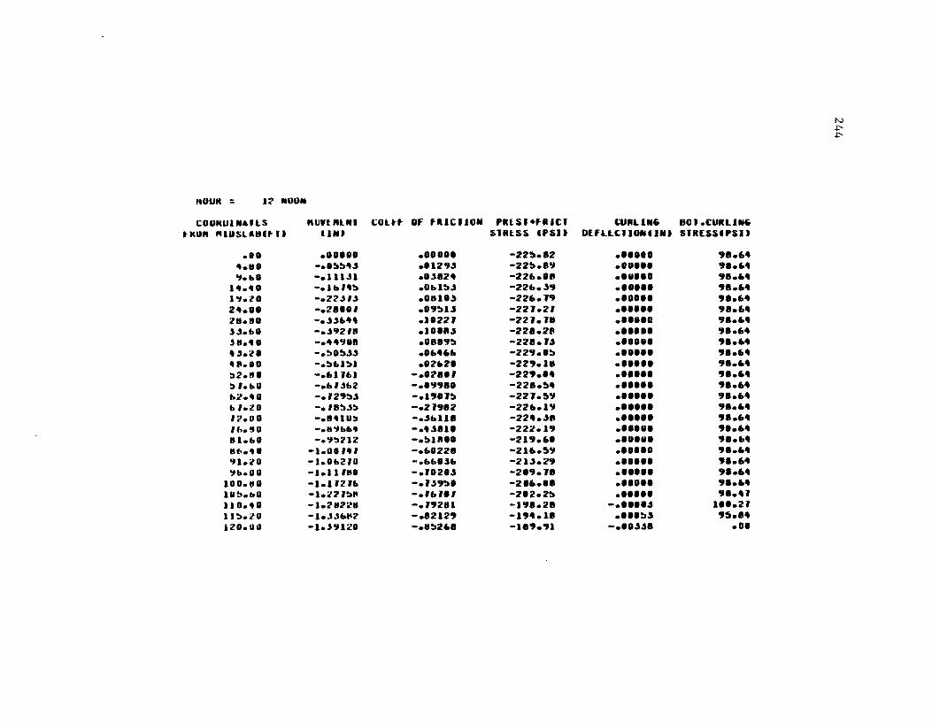
HOUR = 1:1' NOOIII
COUKU.N.,IlS "UnftlNI tHO" "IPSLAHltIJ U."
• 1. •••••• .. It. -.. ~~ .. " "I.b. -.III.n
1 ••• 0 - ..... ,.!t 1..,.lO -.22-".t 2 •••• -.2".' 211.11. - • .t.t .... , .t .... - • .t92' .. ,a.4. -.""J.' • "'.l' -.~.~".t 4".11. -.~"I!tl :::.2.8. -.61 J"I :::. , ... u - ... ,j .. 2 "2.4. -.'2"~.t .... ll -.,a!J"':» '2.DO -.11410:' ,".50 -... ., ..... III .... - • .,:'212 lito ••• -1.00,., 91.l0 -1.0"2ID ~b.U. -1.1.,ttl
100.8. -1.1l2'" IU~.b. -I.:.!'Z '!tl' 1l0.'0 -1.2IZ21 11~.lO -Ie"'''' ...... I ZO.llI. -1.'9120
COlt. OF fRICIION PRlSI·fRICI SnlSS Ifsn
•••••• -22~.e2
..129" -22~.89
•• .se2 .. -22 ..... .1 .. 1!t" -22".39 •• al.'" -22 •• J9 •• 9~1.s -22J.21 • 1'22' -22J.J8 .1 ••• " -22'.211 •• a89~ -22'.U ........ -22".'!t •• 2"2. -229.18
-.'2 •• ' -229 .... - •• 998. -22e.~ .. -.19'J~ -22J.')9 -.2J912 -226.19 -." ... ue -22".". -.'''11' -222.19 -.~u, •• -219 •• ' - .... 22. -216.')9 -...... "' .. -21".29 -.'.2." -2 • .,.Je -.J"'9~. -2.6 ••• -., .. ,., -2'2.2~ -.19281 -1'!Ie.2' -.82129 -19".11 -.8~2.' -189 • .,1
CURLIN .. BOI.CURUN .. OEfLLCIIONIINJ SIRESSIPSIJ
•••••• 98.6 .. •• U ••• 9 .....
• ••••• ge.6 ..
•••••• 98 •• " •••••• 98 ....
•••••• 9 •• 6 ..
•••••• 9 •• 6.
•••••• '!I8.6 .. •• 1 ••• 9 •• 6 ..
•••••• 9 .....
• ••••• 9 .....
•••••• 9 •• 6 ..
•••••• ge.6 ..
•••••• 98.6"
•••••• 9 •• 6 ..
•••••• ge.6 ..
•••••• 9 •• 6 ..
• ••••• 9 •• 6 .. ...... 9 •• 6 ..
•••••• 9 •• 6 .. .... u. 9 •• 6 ..
• ••••• 9 .....
• ••••• , .... J -..... " 1".2' •••• !t.5 9') .... -... "". • ••
I\..)
.p.
.p.
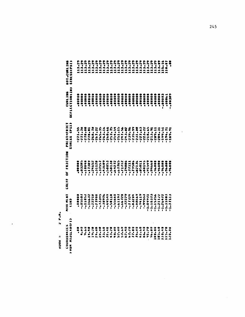
• E •
_. ~-~ .~
~• -~ ~W ~~ •• ~-
• o
--~ -• ~ ~
~
~~~~.~ .. ~.~~ ..... ~~~.~ .. ~. ~NNNNN~NN~N~NN~NN~NN~~ •••• • • • • • • • • • • • • • • • • • • • • • • • • • • ~~~~~~~~~~~~~~~~~~~~~~~~ . ••••••••••••••••••••••••• •••••••••••••••••••••••••
....................... ~.~ •••••••••••••••••••••••••• ......................... ~ •••••••••••••••••••••••••• •••••••••••••••••••••••••• • • • • • • • • • • • • • • • • • • • • • • • • • • I I
- .-·~~mn.~ •. -.~ .. ~~~-~.N~~~ Z •• n~-.~-._.~NNN •• _n._nN •• ~ M •• n •• N5~~n-.--N.N.-n~~--.~. EZ .n •• N-~ ••• n_.N-~ •• ~ •• n_. __ _ - ••• _N~~~.nn.~ __ .~~~. __ NN~~ » ~ •••••••••••••••••••••••••• ;:;, I I I I I I I I I I I I I I I I I 1 ______ ...
E 11111"
~ -~
~~ . -. . ~ . ~ -~ =.E = .E ~=
¥ •
•• = ••••••••••• = ••••••••••• • 5 •• ~.5 •• ~.~ •• ~.~ •• ~.e •• ~. • • • • • • • • • • • • • • • • • • • • • • • • • • . ~.~.~~~~.~-N-N.~._ .. n.n • __ NN~~ .. nn •• __ c.~~ •• ~_~
~-~--
245
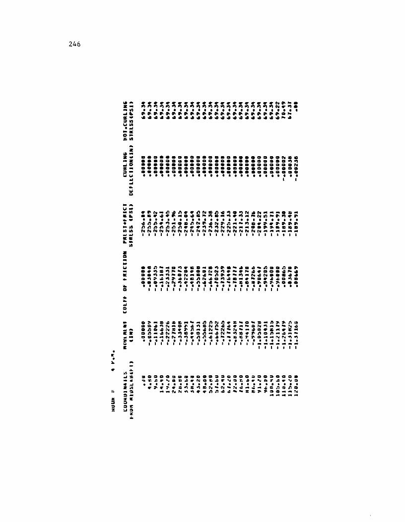
246
... z .... z ... ... z
... 0 ..... :» .. 1011.1
-' ... ... ~ -... 1.1'" .. ~ .. ~ ......
• • ;It ~;It ... .., .... L-
= .. ... 1.1 .. .. ...
;It
~~~~~~~~~~~~~~~~~~~~~~~~~: • • • • • • • • • • • • • • • • • • • • • • • • • • ........................ ~ ....................... ~ .
....................... ~ .. ........................ ~~ ......................... ~ •••••••••••••••••••••••••• •••••••••••••••••••••••••• • • • • • • • • • • • • • • • • • • • • • • • • • • I I
..n~ •• ~ ••••• ~ •• ~ •• ~~~ •• n •• .. ~.~~~ .... ~N~.-.~ •....• ~ •
..~ ... ~~.N· •• -~ •• ·~·N.N •••••
.~ •• ~ •• ~.~N •• ~ ....... - ••• ~.~ • • ..... NN~ •• ~ •• ~-.~::c ••••••••• • • • • • • • • • • • • • • • • • • • • • • • • • • III111I11I111111111111
- .~ ...... ::c .. • ... ~ftNn .. ::c ....... ft~.~. Z ••• ~N ..... ~~~.Nn ........ -.N~ .... --N • ...... • n •• N::c ... n .... N·N·N· ....... ::c .... ::c ... a::Z .~ ..... N~~ ... O~ .... N-~ .... n.n ........ -._ .D ...... NN~~ .. ~n.A-·m::c~ ........ NN~~ • • •••••••••••••••••••••••••• Q 111111111111111111 .................. ... a:: I I I I I I I
• If • ~ ... .. ...
;1)
-'::I: .... c-' Z;;,
Ii .... ~ ~ ..
z sa:: :» :> :> :>a:: :z: 101:>
:II: ...
•••••••••••••••••••••••••• ~~~ .. ~.m~ .. N.~~ .. ~.~ •• ~.r.~ .. ~ • • ••••••••••••••••••••••••• ..... ~ .. ~~::c~.N·N-N .... ~ ... *Qn:>n.
....... NN~~ •• nn •••• Z ............ N ... ......... ...
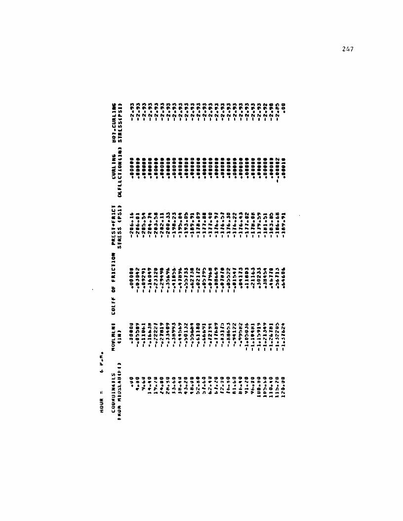
• I: •
... • 101'" a-a ... ea ... ::» • ~c". ... ...
I0Io
~ .... c". ... ... 44 .11. I0I0-• _44 4444
""'''''' •• 1.-
Z Q ... -u ... • I0Io
* I0Io I0Io ... ea c".
44
•••••••••••••••••••••••• N. ............................ •••••••••••••••••••••••••• •••••••••••••••••••••••••• •••••••••••••••••••••••••• • • • • • • • • • • • • • • • • • • • • • • • • • • I
.... ~~ •• ~~~~ ... ~ •• --.N~Ns~ ... n •• .... n~n ... ~N •• ~ •• ~~~~N~ •• nn •• ~ • • • • • • • • • • • • • • • • • • • • • • • • • • •• n~~N •• ~~~.~- ••••• -.~ ... ~.~ ••••••• ~~~.-~~----~-~- •• cc NNNNNNN ............................................ ... 11111111111111111111111111
- CI~ ... &-.~~~~~ ..... ~n~NN .... ~~_n. • •• ~~N .... ~.~ •• ~~.-nN&~&"' ••• N ....... ~ •• Ne.~n ............... ~ ... n ••• ~~N. c •• n .... N~~ ••• ~ .... N-~e.~n.n .... N_ ~_ O= ...... ~N~~.nn •• __ c.~~O ...... ~N~~ »- •••••••••••••••••••••••••• :I 111111111111111111 .................. ... It 11IIII1
::10. ...
II
C ~ CI :z:
.. In.. ::III -c .... z:n -0 0-s:1: CI :II: uo
C ..
•• ~ ••• CI.5 •••• CI •••••••••••• ~z •• ~.~ •• ~~z •• ~~~ •• ~Dm •• N. • • • • • • • • • • • • • • • • • • • • • • •••• .~~~.~~=~.N-N-N~"~_~.n.no
~ ... ~N~~ •• nn •• --c.~~ ..... ~~ .. - ...... ...
247
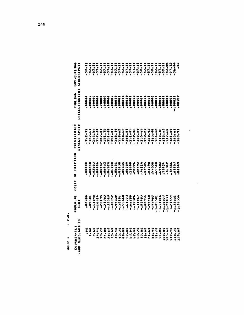
248
• c •
... a
\oil .. a- .......................... ~ .a •••••••••••••••••••••••• NN ~~ ......................... .. c ••••••••••••••••••••••••••• ~- ......................... . ~ ~ ......................... .
a o .. -
~ I ~ ... ... CI
~ •• ~~NN ..... ~~.4N.~ ••• ~.N~·. .. .~ •• ~~N •• ~~ •• N~ ... ~~ •• N .. ~ •• • •• ~ .••• ~4 •.• ~N.-~.~n~.~.~. ... ..N.~~4~~~.~ ... ~.~ .. ~~.~~ .... .............. NN~.nn~ ••• • •• ... . . . . . . . . . . . . . . . . . . . . . . . . . . o 111111111
_ ... ~.~N~N.N.·.~-~r.N ... -~ ... r • ... _~.~n~ .• ~.~~.~~ .... N~.~~ ~ ... ~~ .... -~~n_.N-~ •• ~.~n.n.n2n ca .~ ... N·~ ••• ~ ... N.~C.~~ ... N-~. ~~ .... _~N~~.~r. •• --c.~~ ... _N~~~ · - ......................... . ::I 1111111111111111.1 .................. ... E 1II1111
~ ...
II
~ :1)~= -c C..l 41:1) -:::I ::: ... lirE :::I C.: U:!
x ..
•••••••••••••••••••••••••• .~ •• N •••• N.S •• ~DC •• ND ••• N. • • • • • • • • • • • • • • • • • • • • • • • • • • .~.~ .. ~.~.N-N-~ ......... nQn.
... -NN~~ •• ~~.4-- ••• ~ •• - ... N .... .... _--
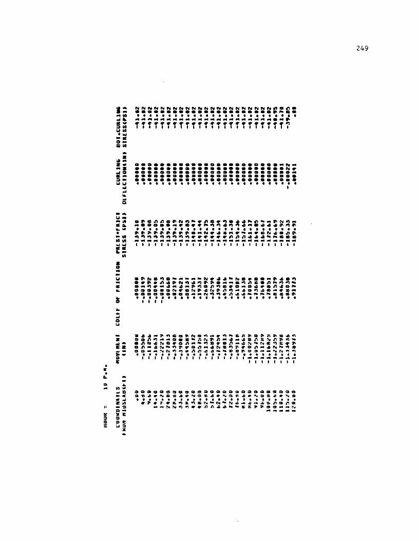
• E •
ca .. .... ... 11.1 ... ;.. .... :')11.1 UII.I 'W ... 0_ 11111.1 .. • ca ... .... ....
... 0 .... :,) .. UU
wi ... 16. .. Q ....
U .. ... :It .~ 16.-• "11.1 11.111.1 ""'.., •• ;.. .. • o .. .. U ... • 16.
~ 16. • .... o \J
11.1
NNNNNNNNNNNNNNNNNNNNNN~.~. ...................... ~~ .. • • • • • • • • • • • • • • • • • • • • • • • • • • ...................................................................... ~ ........................ ~ 1,111'1111111111'1111'111
.......................... N ... •••••••••••••••••••••••• N • ............................ •••••••••••••••••••••••••• •••••••••••••••••••••••••• • • • • • • • • • • • • • • • • • • • • • • • • • • I
• ~.nn.~N~~.n •• ~.44~n- ... ~N~ ... ............... ~~~4~~ ...... 44~~~ • • • • • • • • • • • • • • • • • • • • • • • • • • ~~~~~~~~~ .... N ....... - ..... N4.n~ ~~~~~~~~~ •••••• nnn.44-~ ••• .............................................................................. I1111111111111111111111111
.~N.~.-.- ... -N.44-N •••• "'~~.~ •••• n.~N~.~~~ ........ ~n •• n~~~-• ... ~ .... 4 ... 4 ... ~~.n~ .......... n4.~ •••••• N •• N~.N~n~~4.~~ .... ... ............... N~~.n.~-~_- ••• ~ • • • • • • • • • • • • • • • • • • • • • • • • • • I 1 I I
- .4~.~~ •• ~N.~ .... ~-.~~.~~~.~~ 2 •• n~~ •••• -~N~n ... 4~~.n~~n~~wI- .n •• N ••• n ... -~ ••• n~~N-N.~ •• ~ E •• n"'~~-~~ •• n"'4N.~~ •• n"'~N-~ • • _ •• ~.NN~~.~~~~ __ •• ~=a._NN~~ _. . ........................ . = 11111.11111111111 ............. ... II: I 1 I 1 I 1 1 I
;.. -II
a: :I = :x::
-"" 1/)"" .... :D _c ...... 2;1) ... :11 = ... :II: = =1: :.1=
:II: ...
•••••••••••••••••••••••••• • Z~.~ •• ~.N.z~.N.~~.~a~~.~a • ••••••••••••••••••••••••• .~.~ •• ~.~CIIN-N-N~.~~~~n.n. __ NN~~ •• ~~~~ __ cc~~ ..... _N ... ....... _-
249
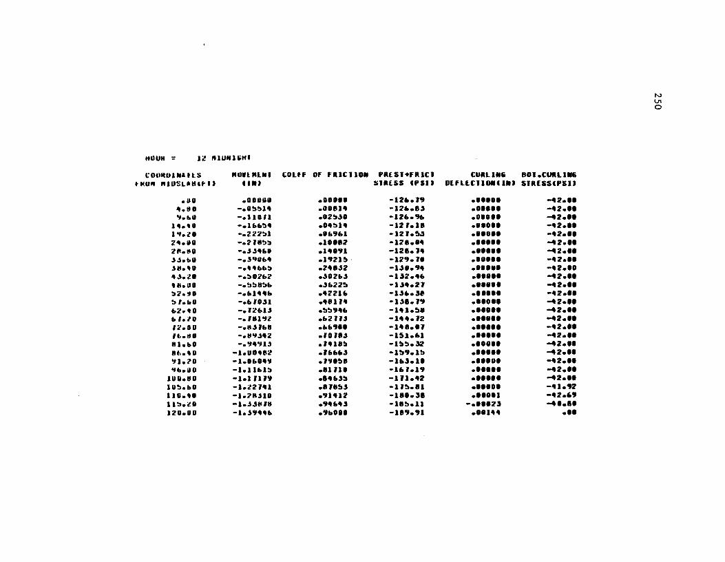
HOUM = 12 ,nU'UIJHJ
c: OtuUH ... It S "OIll"UIl COltf OF FUClIO .. t 1(01'1 "JIlSL.ltU It U .. ,
• 111 • GIOOO .GOO •• 4.BO -.I!)!)I' .0181' ".100 -.IIGI1 •• 2!)".
I •• t' -.I .. "!). •• '!)14 • 4f.l. -.222!J1 .'''''''1 24 •• G -.218!J:' • I ••• Z 21'.lIU - • .5.,,'''' .140OJI oS"".bU -.""V,,4 .1'921~ . llt.t. -....... :. .2 •• .,,2 • .".l' -.:'.2 .. 2 .".2 .. " til. III -.!J:'B!J" • ""22:' :'2. !I I -........ •• 221 " !J'.bO -."'."1 .'811' "Z.'O -.12 .. 1.5 • !)!), ...
",./V -.'BI.,2 ."21'" 12.00 -.lI.", .. 8 ..... " .. ,t..ttl -.lIIJ""'Z .10 ,." 81.". -."'''1' .,.18:' III>.tl -1.00'82 ., ...... " '1 •• 10 -1.1".'" .n.5. IJ ... If 0 -1.1161!» • Bln.
lOlI.lfO -1.lll ,., ..... ,,~ 10~.&. -1.22'41 •• Je:'J 118 ••• -],1''''18 • "I.IZ Il!J.l' -1.oS"II" ." .... " 120.00 - •• "9 .... ." ... ID
PR[SI+fRIt:1 ~"f.5S CPSI J
-12".'OJ -12".11" -12 ........ -12'.1. -12'.~.s -12 •••• -12 •• )II
-12OJ. " -I"'.OJ' -1"2 .... -."4.2' -1" ... .1.
-I" •• '" - .. 1.:'. - .... '2 -..... , -151."1 -1:'!).32 -1~".1!)
- ... .1.11 -1 .. 1.1" -Ill.'! -II:' ••• -1 ••• .1 • -IB!).1I -1 • ., • .,1
t:URLI .... BOI.t:URLI" OlfLlt:IIOICIN. SIRfISCPSI.
•••• 1 • -42 •••
•••••• -.2 ••• .1 ••• ' -42 •••
• ••••• -42." . .. , .. -.2 •••
•••••• -42 •••
•••••• -42 ••• .'U'" -42 •••
•••••• -'!.IO
•••••• -42 •••
•••••• -4! •••
•••••• -.2 •••
•••••• -42 •••
.'10" -42 •••
•••••• -42 •••
•••••• -.2 •••
•••••• -42 •••
•••••• -42 •••
•••••• -42 ••• ....... -.! •••
• ••••• -42 ••• ...... -4!."
•••••• -'1.'12 ••••• 1 -42.6'
- •••• Z.1 -4 •••• • "1" • ••
N 1Il o
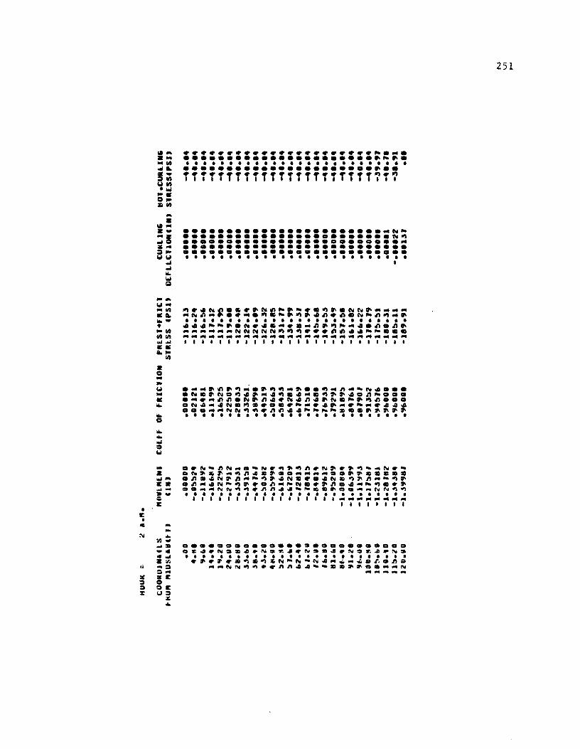
-... U'" ... w .:ct. "' ... • _III lIS lIS .... "" 11:': ct.,..
a o ... -U ... .: ...
lIS
...................... ~ ... ......................• ~ .. • • • • • • • • • • • • • • • • • • • • • • • • • • ••••••••••••••••••••••••• ···T·T···TTT·TTTT·T·TT~·~ III I III I I I .11
•••••••••••••••••••••••• N•••••••••••••••••••••••• N~ •••••••••••••••••••••••••• •••••••••••••••••••••••••• •••••••••••••••••••••••••• • • • • • • • • • • • • • • • • • • • • • • • • • • •
~ •• N~.~ •• N~~.- •• ~ •• NN ....... .N~ .•••.• ~.-.~ •• ~.~.N~~~ .• • • • • • • • • • • • • • • • • • • • • • • • • • • ••• -- •• N •• ~ ...... ~.~~ ••• ~.~. .................. NNNNN~~~ ••• ~~ •• -~ ••• .................................................................... 111111111111111'1111111111
... ..N-~N .... -N.~~~n.N~.~~, ... N.• .N~~~"'~~ •• ~ •• "'''''''''' •••••• SI •• ...... • ~ •• N.~"'-~~.N •••• N.~~n ... -~. Ea .~"'.N-~ ••• ~"'~N •• ~~ •• "'_~ ••• ~- O ....... NN~~.nn •• -_ ........ _NN~~ · - ......................... . ~ 1111.1111 •• 111111 ..................... ... E 1111111I • E • . ...
:1.1 ... :1'1'" ...lSI -c .... • :IIi .1 _ ~
::\ ... :Ie iKE ::; 0 ::; OE z: u::;
" ...
•••••••••••••••••••••••••• .C •• N •••• N.~ •• N2 ••• N.~~.N. • • • • • • • • • • • • • • • • • • • • • • • • • • • ~.~ •• ~.~~N-N-N .... _ ... _.~.~ •
...... NN~~ •• ~~ •• --.SI~ ......... N ... .... ~ .. ....
251
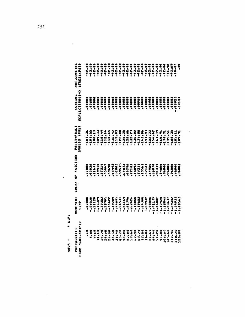
252
• c •
... • "" a .. ... .. g ... a~ ... .. ~
! ..... "' .. .. 11'.1 ... ..... • .. tit tit 11'.1 ... "" •• .... • o .. • '" .. • .... ~ o
11'.1
c ...
II
... (1').... :. _c . .,., z:n -:l =.c = =11: ~:a • ...
•••••• • •• • •••••••••••• N~ •• •••••••••••••••••••••••••• • • • • • • • • • • • • • • • • • • • • • • • • • • NNNNNNNNNNNNNNNNNNNNNN .. N. TTTTTTTTTTTTTTTTTTTTTTTTT
......................... ~ . •••••••••••••••••••••••• N • •••••••••••••••••••••••••• •••••••••••••••••••••••••• •••••••••••••••••••••••••• • • • • • • • • • • • • • • • • • • • • • • • • • • I
. ~~~~.~N~.~.-N .. -NN~--- .... · "~ ........... N.N ••• ~N.-.-~"_~ • • • • • • • • • • • • • • • • • • • • • • • • • • --.~.N .• ~N~.N.~~-N ... ~.~.~~ ........ _._NNN~~~ •• ~~ •• __ •••
._-----------------------.,111111111111111111111111
.• ~ .•......••.......... ~.D
.m~.~.~~.~.m~.~:a~~.N.&~.~:a
• ••••••••••••••••••••••••• .~.~.&~.~&N-N-N~-~.~.n.n. ~~NN~~ •. nn~~--.c~~.:a-.N ...... -...
• II: •
... • r.I~ •• -. .10 a~. ww ..
.I .. .. Q ....
w~
-~ a .. .... • -~ ~...,
101 .. aa a.-
• o --f.) -a i/o, .. o i/o, i/o, .. o I.l
~
...................... ~.~ . .........•............• ~ .. • • • • • • • • • • • • • • • • • • • • • • • • • • ••••••••••••••••••••••••• ····TT····TTTTT·····TT~T~ 1.11 •• 11 1.1'1 t •
....................... ~~........................ ~~ ......................... ~ ................ ~ ........ . •••••••••••••••••••••••••• • • • • • • • • • • • • • • • • • • • • • • • • • • I
.~~~ ••• ~~.~.-N •• -NN.~~~~~~ ~~~~.~~ ... ~.~ .... N.~.-~~~. • • • • • • • • • • • • • • • • • • • • • • • • • • -- ••• N ••• ~~.N •• ~~~.~~.n.~. •••• ~~~~~~~N~~~ •• ~~ •• -- ••• ~~~~~~~~~~~~~~~~~~~~~~~~~~ 11111111111111I11111111111
- •••• ~.N •• _ ••• nN.N •• N~.N~~. • .~NNn.Nn.~.~N~ •• ~n-.N.-a~. ~ .... ~~-~ •• N.n~- ••• ~.n~ •••• ~~n cz .n~.N-~ •••• --~ ••• n"'.N.~ ••• ~~ •• "'_NN~~.~n •• --z •••• __ NN~. •• • ••••••••••••••••••••••••• ;;> I I I I I I I I I I I I I I I I 1 ... - ............... ... C II11I111
C ... .. 1/) • .... :. _c c...J • ;1) ... ~ 0'" XII: :.lI :.lI1: :.I:.lI
X ..
...... ;. ............. ;. .... . ~z •• N.e •• N •••• N~ ••• N.Z •• N. • ••••••••••••••••••••••••• •••••• ~.~.N-N-N._ ...... n.n •
...... NN~~ •• ~~ •• --.& .......... N ~- ... ... ..
253
254
• • • • • • • • • • • • • • I
• • I
• • • I • • • • • • • • • • • • • • I I
C • • Cit I ., • • I I • • 110 I I
0 • • I , • • CiI , I • • • .., I I • • I I • • I I

APPENDIX 0
USTING OF COMPUTER PROGRAM PSCP1

!!!!!!!!!!!!!!!!!!!"#$%!&'()!*)&+',)%!'-!$-.)-.$/-'++0!1+'-2!&'()!$-!.#)!/*$($-'+3!
44!5"6!7$1*'*0!8$($.$9'.$/-!")':!
RR401-3/DD
e
PROGRA~ PCPl(lNPUT,OUtPUt,PlOt,tIP(~:INPUT,TAPt~:OUtPUt,TIPE7:PlOt
U
e ecceeeceecccececccececcccceccececcccccCCCCCCCCCCCCCCCcccccccccccceccc c e c C e e c. e c e c e e c e c c. c
PROGRAM PCPl - A~ALYSIS OF PRlSTRESSED CONCRETE PAWE'ENTS CONSIC~RI~G THC INELASTIC NATURl Of THE SlAe-BASE fRICTION fORCES, fESRUARY .98t.
T~IS PROGRIM WAS DEWElOPE~ ~Y ALBERTO MENDOZA AT THE C(Nt(~ FOP. tRANSPORTATION RlSEARCH, THE UNIVE~SITY Of TElAS AT AUSTIN, IN RES[ARCH PP.OJECT 401. 'DESIGN AN~ CONSTRUCTION or PRL~TRlSS[V CONCRETE PAV[~ENT~ fDA OVeRLAY APPLICATIONS', CONQUCTED IN COOPERATIO~ wItH THE TElAS STATr DEPART"l~t or HIGHWAY! ANO PUBLIC TRANSPORTATION, ANO THt FEDERAL HI'~AY AO"IN1~lR'TrON. DOCUMENTATION REL'TtD to THE DEVELOPMlN1 AND APPlleATrnN Of 1HIS PROGRIM IS PRESENTED IN CTR RtPORT NO. 4DI-7, 8T ILbERTO MENDOZA, a. ~RA~K MCCULLOUGH AND NtD H. BURNS
T~IS PROGRIM DOEs NOT CO~STITUTE A STANDARD OR POLICY OF t~£ Tt.aS SOHP1. ANT USER SHOULC ICCtPT RESPONtIWILITY FOR THE ACCURICY OF THl IN~UTS IND VILIOITY OF THr RESULTS.
c ecccccecccccccccccccccccccecccccccccccceccccccccceeccceeccccccceccccec e '
C
DI"~HSION VLCTOR1(20)>,VECTOR2(2U>>,ARR[(24' OI~L~SlO~ AG(8»,PCTe(8"PCTT(S) DI~[NSIOH CURH()"P(IDO)
c eccccccecccccccceCCCCCCCCCCCctCCCCCCCCCCCCCCCCCCCCCCCCcccccccccccccc C c C C C C C C C c e e c e C C C C C C C C
LIST OF VAAIABLES
INPUT WARIAeLrS:
VECTORI: ALPHANUMeRIC I_FORMATION TO IDENTIFY THE PR08LEM SLAe LENGTH (fT) Dl :
o : SLAB THICKNESS (IN) NILO : NO. OF INCREMrNTS tONSIDEREO BY THC PR05RAM FOR ANALYSIS
OF SlAB HALF N ....
TOL ALTOT
lTOT G
PR CA£[P
ilK
: MIXIMUM NO. OF ITCRATIONS : RELATive CLOSURC TOLERANcr CPtRCENT) : CONCRETE THERNAL COEFfICIENT OF CONTRACTION OR EXPANSION
elM/IN-Dca.F) = fiNAL SHRINKAGE STRIIN (IN/IN' : CONCRtTE UNIT VEIGHT (PCF) : CONCRETE POISSON RITIO = CONCRETE CACEP COEFFICIENT = NO. Of POINTS IN CO"'R[SSIVE STRENGTH VS AGE
RELATIONSHIP PAOVIDEO BY USCR AGEUIl,: IGE IN DAYS FOR POINT I OF RELATIONSHIP
COMPRESSIV' STRENGTH fOR POINT I OF ReLATIONSHIP CO"'(I):
257
258
:'1> 51 5~ ;)t;
b~
01 c< .. 3 ~.
1>':. bf, 01 ~fl ,,9 H! 71 1:! 7:' 7_ 7~ 7f: 11 11> 79 80 81 82 8l 8" 8~
8~
81 .It II 8'" 'Hoi 91 92 9l .jOt
95 9b 97 91)
9'3 100 101 10::: lC3 10. 10!l 101> 107 I as 10'3 110 111 112
RR401·3/DD
c C , C C t t C C t C C C C C C C C C C C
c c c C C C C C C C C C C C C c;
"1 = NO OF POINTS IN THl fRICTION COEFFICIENT V~ DISPLACEMENT
lV(I. UU(J,
SK S5 SA
RELATIONSHIP = 01SPLACE~(Nl IN INtHES FO' POTNT I OF RELITIONSklP = FRICTION COEFFICIENT fOR POINT I ~, RELATIONSHIP ~ K-VILU( O~ TOP OF SLAB SUPPO~TINC LAYER «PSI lIN) = STRA~~ SPACING (I~) = NOMlhAL AR~A OF THE STRANDS «SG.IN) = STEEL YIELD STRESS (KSI) : STEEL ELASTIC MODULUS (PSI) = STEEL THERNAL COrFFICIENT (PSI'
FPf ES
ALS NPER = PAIRS OF SLA~ MID-DEPTH TEMPERATURES AND TOP-TO-801TO~
TEMPERATURE DIFFERENTIALS PROVIOEe A1 2-HOUR INTERVALS CURH = CURING HOUR «Ih THL SCALE OF C TO 2- HOUR~)
CU~'L"P= SLAR MID-DEPTH TEMPERATURL A' THE CURIN& HOUR CDE~.f) AOIII): MID-DEPTH T£MPERAT~RE FOR DATA PAIR I (DE6.F)
TOIFII'= TOP-TO-80TTOM SLAB TrMPERATURE DIFfERENTIAL FOR DATA PUR I IOEG.f)
NS = NUM~ER OF POST-TENSIONING S'AGES IAGE : TIME SINce CURING TO COMPL(TIO~ OF POST-TtNSIONING
STAGE I «HOURS) PSCI' = AMOU~l OF PHrSTR[SS COMPLETED PER STRANO AT POST
T(NSIONI~G STaGE I IKSJ) ITOA = NUMe(R OF OAY~ SI~(C CURING TO 8EGlhNING OF PERIoe
or AhALYSIS CON~JOrREu
OTH~R VARJA~LES:
FPA = 'U.lIlMUM usn
TeNSILE STRESS ALLO~ED BY ACI IN STEEL TENOON~
SFF = INCR£MENT OF CO~CRlTE STRAIN ISINcr APPLle.TION OF LAST POST-TENSIONING FORCE' THAT RESULT! IN A CHANGE of Tke PRESTRess LEVEL IN THE STRANDS (IN/IN)
ELONG = CHANGE IN THe STR(SS IN TH! STRINDS our TO THE CONCRETE STRAIN INCREMENt SFf IISI'
RLLA. = LO~S IN THC STRESS IN THE STRANOS DUE TO STEEL RELAXATION usn
PRFINAl= TOTAL PRFSTR[SS IN THE STRlNOS AFTER Losses (KSl' SFINAL = PkrsTR~SS LEVEL IN THE CON(k£T[ AfTER LOSStS (PSI)
c eeeccecccccccccccceeccecccececccecccccceeccccccCCCccccecccccccccccc c C
c
COM"ON/~lOCKI/DT(10.25).T"IOCI0.25' COMMON/bLOCK2/IK.A5EUC20'.COMP(20' CO"MON/blOCkl/Ml.lU(20).UU(~O' CONMON/tilOCK4/1R.IW COMMON/~lOCK5/KI.CURTEMP,A5CI00'.ADTII00'.TOIFCI00'.pP(100' eOMMON/8lCCa6/G.COMPF.ALTOT.ZTOT.CRl£P.'R.Sk.SL eOMNoN/tLOCk7/DL.NILO.NTEMP.TOL.NMAX COMMoN/BloeKI/AL.£L.ZZ.SA.SS.PS(lO'.A'EP(10) CO"MON/~LOCk9/".ZC200'.Uf200) eOMMON/8LOCk10111C200,.XC200"fX(200'.STF1(200J COMMON/tiLOCKll/e.H.R COMMO./6LOCk12/TOACIOJ COMMON/BLOCK13/CPf.CPM.IZF.RELA.,fPY
C INITIALIZE VARIABLES fOR HEADIN'S, COMPRESSIVE STlr.5TH VS
II ~ II ~ II:' 1h 111 111" II ';j 12t 12. In 1~~
1~" 12: Ilb 121 128 12" DO Ul 13~ 1.!~
1~· 13:, 131:> 1! 1 Ill> lJ'l
"'0 lU 14;' H:l I,,, I"! IH 1 '17 HI>
1"" I !'IO 1 !'I 1 1 :. .. If>~
I!>" 1!'1~ l!>b 157 l!'lS 15S 1 .. C. 161 1&Z 1b3 11>4 u.~
IE.(; lbl he H,'j
RR401-3/DD
c c
c
c c C
c
t C C C C
c c c c c
100CI
1 020
Jc.JO
1031
103.< c c c
1052
lObO
1010
1080
108£0
t C
AGE ~CLATIONSHIP AND INPUT/OUIPUT PARAlltT[RS
DAIA AkR(IZ"."H.--.1 DATA A&f/D •• l •• 3 •• ~ •• T •• l, •• 21 •• 2e.1 OAIA PC1C/O •• I!> •• 38 •• 53 •• &3.,82 •• 9" •• 100.1 ••••••••••••••••••••••••••••••••••••••••••••••••••• lR=o!i 11/=06 • ••••••••••••••••••••••••••••••••••••••••••••••••••
PIUNl lllLE
Cr.:'L n lLE
INPUT ANO CCHO-PRINI OF GENERAL cATA
••••••••••••••••••••• • • • R[AD INPUI DATA • .. .. •••••••••••••••••••••
PMOGRA" A~D PkOBL[M ID[~TIFICAII0~
REAOClk.IOOO'VtClORl FORMI. TC 20'" WRlllflw.l020)ARRE FOR"AT(IHl.~e/),TIT.24.") I/AIY[Cl •• 1030'ARR(Cl'.VECTOkI •• kktel' FORMATC/.TIT.''' •••• ZCA4 •••• L4' I/RlllClw.lu31)ARR(el).Aq~£Cl'
FORMA T(/,l1 7. A",3l1t. ·lCHO-Pf. HIT OF GEN[RAl OA TA'. 3U. A4' w~Jl[elw.1032'ARRt FORMATe/.TIT,2"A.,III,
R£AO PROblCM DefINITION
· Rr.aeI~.10"C'OL.O FORMAT(E.FIIJ.O' R£ADCl~.lO~O'~llO,NMAA.TOl FOR~AT(21~.rI0.O'
Will TE ClW.1O!l2' FORMATelll,IHO.33X,33CIHe') 1oI.I1EClIi,10601 FORMATtJ4 •• '. PRObLEM DEflhlTlON WRIHCh.l010J FORM'IC3"X.~~CIH." WRITEII •• IDIO'Dl,O FORMATCIHO,45A.25HSLAB LEIGTH eFT'
• 46X,25HSlAB IHICKNCSS (IN' WRIlEClw.ID66,N1Lj,NMA.,TOL FORMAT(46X,25HNO.OF INCREMENTS
• 4'X,25HMAX. NO. OF ITERATIONS • 4'X.25HREL. CLOSURE TOLERAWCE
TOl=TOl/IDO.
READ COhCREIE PROPERTIES
• 'J
=,FlO.ll =,FIO.1 ,
=,1101 =,1101 =,FlD.llllJ
259
260
170 111 11: 113 11~
115 11i. 171 178 11';
11'C al 18" 1!\~
1 B~ IB~ I fit:, 181 188 18<;; l'J!) l'H I <;z 1'1! 1 ';11\
lC;~
1'10 191 l'e 1'''' 200 201 :02 20 2C4 Ho; 200 201 <'Of' 209 210 211 21<! 213 214 215 2lL 217 2111 219 220 221 222 223 22'1 225 226
RR401-3/DD
c
I o 'HI
Ii 10
c C C
1120
1121
1122
C t C
11.30
1131
11l~ C C C C
IUD
1200
• • • •
R(ID(1~,1040'ILTOT,lTOT,G.'R,CR(EP IF(CRLlP.[Q.0.0'CR[[P=2.35 IF(PR.r'.0.G'P~=0.15 WRIlE O.,1l'52' wAI H.(lIt,1090) FOR"I'(~41,.. CO~CR[T[ PROPERTIes WRI It (l. ,I 070) WRIT[(IIt,lI10'ALTOT,ITO",,~R,CRt£P FOR"ITC1HO,4S',2SHTH[R~IL COEFFICIE~T
4~.,2SMTOTAL SHRINKIGE '161,25HUHIT WEI'HT CPCF' 4~I,2SHPOISSON 'ITIC '161,25~CR(~P COEFFICIENT
.' , =,£10.31 :,EIO.31 =,FIO.II =,F'10.21 ::.,FI0.211"
INPut AG(-CO"PRESSIVE SlRENGTH RELlTIONSHIP
RCIO( IR,1l2DUlK,UGCU( J) ,COMP' 1",1::1 ,7)
F'OR"ITC15,~I,l'1F5.0' WRIl H 1 .. 1121) F'OR"II(IHl,~(/" lolA I H( 1Io,ID~21 W~l Huw,1122' FOII"".53I,' • CO~PHS~IV( .'1
• 331,' • STRCIiiGt" OITA .,» W"I1Ul",1070) If(kK.&l.I'GC TC 1200
RlLITIO~~MIP IS NOT CSlR-~UPPLl(O
IF(AG[U(I'.EQ~2£.'GO 10 1135 WR1TEClW,l1Jt:i' ItRlTtClW,l1lU FORMATCIIII,lhO,281"LRROR,STRENGTH VALUE PROVIDED IS NOT FO~ 28TH
• Cl'., F~R"ltCJZI,'... [IECUTIOh 180Rt£0 •••• , GO TO 2&00 ICl=1I
A6!-CO"P~E~SIVt STRENGTH RELATIONSHIP DE.ElOPEn FROM 28TH OAT CO"PRESSIV~ STRENiTH SUPPLIED BT USER
WRITE ClIlt11'1H FORMATCIHC,ll.,'THE FOllOWINi STRtNiTH RELATIONSHIP MAS'I
• 371,'DE.ELOPEO BlstD ON THE R~'OM"ENOATION GIVEN'I • 371,'eT THE u.S. 8UREAU OF RCClA"ATION AND THE'I • 3Th'ZITH DAY COM'RU. StRENGTH PROVIDED B' USER"
COM'CI':CO"PU, CO"PF'=CO'"1) 00 n~D 1::.1,1 AGEU« I' ::1:;£ (I' COMPel,::.tG"P«8)·PCT'«I"IOO. CONTlNut GO TO 1%10 tONTINUl IFCC'GtUel).EG.O.J.AND.etDMPCl'.EG.O."GO TO 120. MRlHUIt,120U
232 ~JJ
23'1 ~J:>
2lt. 2!1 2'11 2)':
2- C ~U ,.~
243 ~~~ 24::> :!HZ"1 2 .. e 2.'" 250 251 2~2 2:,l 25" .5:-2:>(;; 251 ,511 2:>'> 20'J
21'..1 2ri. ~ 2bJ 21>4 2E.5 2500 261 268 ;:1>9 nc 211 212 2n ... h 215 21t 211 278 21'1 280 281 282 2!1)
RR401·3/DD
WRI H.Cl\ •• l1)J) 1202 FO~MAT("",lHO.281,'ERROR.THE AGE-STRENGTH RELATIONSHIP DO(S MOT
.8(~1~ .1TM (0.0.0.0.') GO TO 2000
1204 (O/lltll11l)( IF(KK.GT.7)~rAOCIR.1206)(AGrUCI •• C~PCI).I=~.kl('
1206 FO~MA1CCIOI.14fS.0)) KL:.I(K
C C R~LATIOhSHIP IS USER-SUPPLIED C AG~-CO"~RESSIV~ STRCNGTH RELATIONSHIP IS USER-SUPPLIED C
WRI TE. C 1.,12301 1230 fORMA111HO,)8X.'TH[ COMPRESSIVE STR(IiI&T~-A&r RELATIONSHIP"
• 391,'AS SU~PLIEO BY USER IS:" 00 1217 1=2,1(1( IFIAGtuCJ).LT.28.)GO TO 1277 SlOPE:ICOMPCI)-COMPll-l')'C'GfU«I)-AGEuCI-l)) COMPF=CU~P«I-l)·SLOPE·C?8.-AGlUCI-l»)
';;0 TO 12110 1211 CO"lTJNUf
COMPF =COMP «KI( ) 1280 COllllJNUL
WRITECI.,1290)IA&rU(I),COMPII).I=I.KL) 12~O FOR~ITtlHO.4LK,' AGr COMPQlSS1V["
• 46)(,'(OAYS) STRENGTH'" • C461.f5.1.':1X.F~.1))
c C IMPUT COCfFIClrlllT OF FRICTION-ulSPLACt"CNT RtLITIONSHJP C
129b
1300 C C C
1320 C C C
RlAJ'IR.IJ~Q)~,C1UCt).UUCI),J=l,7)
IFI"1.bT.7)RCAOCIR.120~)ClU(I"UUCJ),l:8.Ml) w~rH.nW,1(J::'2)
IIIRlTE U •• 12'H' FOR"ATC!~.,'. SLAb-SASl FRICTION PROPERtIES •• ,
• )41... l-U RElATlOMSHIP •• ) WRITElh.1070) IF(Ml.(Y.l)GO TO 1300 IF'"l.&[.Z)GO TO 1~20 WRITCCIw,1296) WRITECIW,113U FORMATClHO,281.'ERAOR,TYPE OF fMICTION CURVE INPUt NOT IOENTIFIEO'
.) GO TO 2000 COUUIU£
RELAtiONSHIP IS LINtAR
ZU(2):ZUCl ) UUC2J:UUU) lun )=0. UUCl )=0. GO TO 1330 CONTINUE
RELAtIONSHIP IS EXPONENTIAL OR MULTILINEAR
261
262
28_ 295 l8b 21>7 l&1! 23'1 2 'HI 2<;1 2'12 293 2~_
2~~
2'11. len (9~
279 300 301 30:' Ju3 30_ 3Q!i 30f. 301 3011 .lOr, ::10 311 312 .H3 JH 31':. l·tf., 311 318 319 320 321 3.< 323 314 3'<5 3ZE; 3:17 321.' 32'i 330 331 332 333 334 335 33t 337 338 339 .HO
RR401-3/DD
1322
lJ30
1140
13~0
1360
t C C
143~
t C C C
1100
IFCCZUC1'.EG.O.I.ANO.CUUCII.£G.0."GO TO 1330 IiRII£.I1I/91322' IiRIH(JI,r,l1l1' FO~MA'IIIII.IHD.28X,'ERROR,TH( l-U RELATIONSHIP DO(S N01 eE~IN WIT
-N (0.0.0.0' I,. 60 TO 2000 COlolIINliE IFCM1.[Q.l'WRITECIW,11.0',UC2"UUC2' FOkMA"lHO,36X,'T'P[ OF fRICTION CURVe IS A STRAIGHT LINE'II
• 31.,'MOVtMCNT IT SLICING =',21,F6.31 - 11X,'MAXIMUM COEFFICltNT OF 'RICTION=',2I,F6.1' JFCM1.EG.2'WRtTEClli,11~0'ZUC2',UUC2' F~RMATllHO,361.'T'P, OF FRICTION CURVE IS AN EIPONENTIAL CURVt'll
- 111,'MOVEMEN1 AT SLJOING =',21,".31 • 31X,'M'XIMUM COEFFICIENT OF FRICTION=',2X,'6.3'
IFCM1.GT.2'WRIT[llW,1360'CIUCI',UUCI',I=I,Ml) FO~MAT(lHO,3'1.'J'Pl OF fRICTION CURVr IS A MUlTILINEAR CURVE'II
-,41X,' lCI' UCl"'1(46X,F6.3,8X,'6.3'J
INPUT PROPC~Tlts OF SLIH SUPPORT
IIkI TE' 110,1121' Wr.ITC(J",10~2' IIRIHU",1!!42' FORMATe33x,'. STIFFh~SS OF SLAB SUPPO~T ." WR 1 T£ (J 11010 lCIJ RCADe Ik,104Q'SK IiRITE(J",l~44)SK
FOk"lT'lHO,4~X,2~~K-VllU£ OF SUPPOR1CPCIJ =,rlO.Z)
~['~ STLEl PROPERlItS
R[AO(I~,1040,ss,s.,rp"(S.'LS IF(SS.LQ.O.)GO TO 143~ WRITE(h.JO~2)
111\1 l[Ch,H15) fORMAT(33X,' - STtEl PROPERTlts IIRJTEU .. ,101Q) SPT:SA·l0C./lSS-0) wkITE'I~.J42a'SPT,ss,SA,rp,.£s,ILS FDRMAT(lHO,4~X,2'HPERC£NT RlINFORCE"ENT
• 461,2~HSTRIN~ SPACING CIN' + 46X,~'HhO~1~ll AREA fse.lN) • '6X,2~H'ltlC STRENGTH CKSl) - 461,25HClAS11C MODULUS CPSI'-- 461,25HTHER"lL COEFFICIENT
FPA =0 .94 .rp, COMTINUE
. " =,FlO.31 =,FlO .21 =,fl0.31 =,FI0.21 :,[10.3/ :,tlO.3/,
INPUT CONCRETE TEMPCRAtURES FOR FIRST PCRIOD 'NO tIME 'ND '"OUIT OF PRESTRESS FOR EACH POST-lENSIOaING STAGE
WRIT£CIw,1020"RR£ WRI'ECI~,1030"RREC1,,'£CTOR1.'RR£Cl' WRIT[CJ~.170D"RRECl).'RR[Cl' FORMATC/TIJ,A4.19X.'PREDIC110a or PA'E"ENT STRESSES fOR lalTIAL PC
lRIOO'.191.'.'
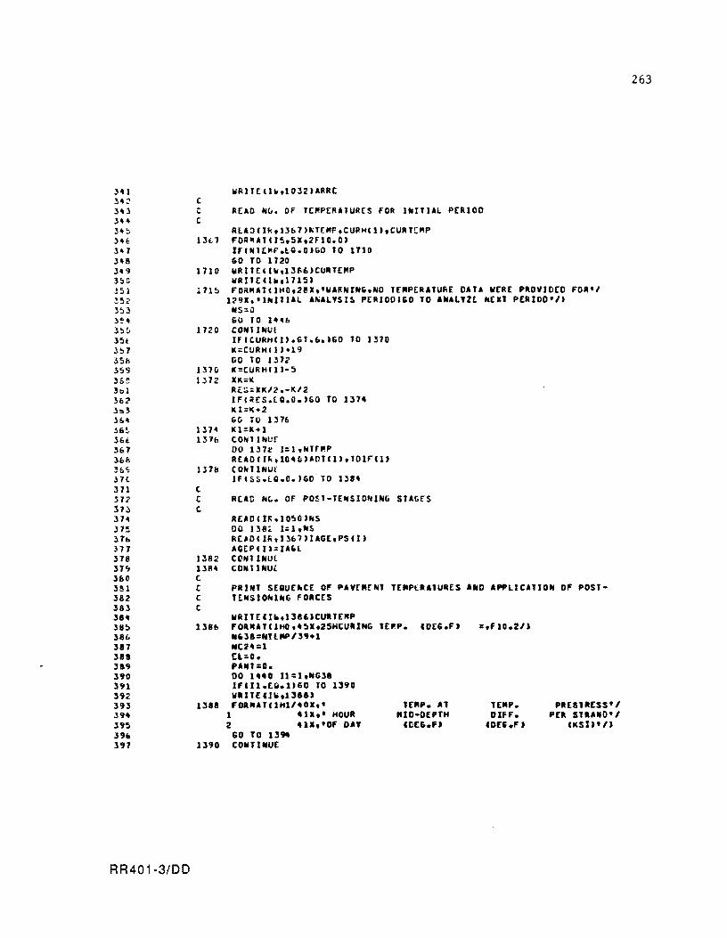
;,.. 1 34:'-34J )." ,H!:l ) 'It: ,'SItl ).8 ).9 ]~G
~5I
!~2
3!>J J~4
J!:l5 3~t
3!ll JSI! 359 36~
hI 3b:? 3 .. ] 36'1 J6~
3&t. 367 lbE; '6<; H<. 371 312 31;) 3H J15 3h :n7 318
3"" 3&0 381 382 383 38. 38~ 38C. 387 388 389 390 391 392 393 39. 19~
396 397
RR401·3/DD
c C READ NL. OF TEMPER'lURES fOR l~I'J'l PERIOD C
Rl'~IIk.13b7)~Tr"p,CURHCll.CUR'C"P 13~1 FOR~'TIJ~.5X.2FI0.0)
lfINltMF.lG.OIGO 10 1710 60 TO 1720
1710 WRIlrCIW.1386)CURTEMP WRII E' h ,1715)
1715 FO~"'T(IHO.2eX.·W'RN1N&.NO 1£MP[RATUfiE OAT. WERE PROVIDED FOR'I 1:?9I,'INI11'l 'N'l'SI~ PERIOO;GO TO '~AL'lt N[XT PERIOO'/)
IIIS=O GO TO 1".&
1720 CONTINUl IrltuRHII).Gl.6.'GO TO 1370 K;CURHll)·19 GO TO 1372
1370 K=CURHll'-5 1372 XK=K
Ill'll 1311:>
131&
c C t
1382 138'1 t
Ri::;=XK/2.-K/2 IF(RES.[Q.O.)GO TO 1374 11.1=1(·2 Gli .0 1376 11.1:.11.41 tON1INur DO 137e I=l.NTf"P R[ADIJk,104~I'OT(1).tOlrCI)
COUINUr IF(SS.lO.O.)GOTO Il,.
RC'D NL. OF POSt-T[NSIONING STAGfS
RtAO OFi ,I O!lUNS DO 138:< l:I.~S
Rt'D(I~.13b')I'GE,PS'I' 'GEPCU=U'l COIiITlNUl CONTlNUl
C C
PRINT SE8UE~CE OF P'VEMENT TERPlRATURES A.O 'PPlIC'lIO~ OF POSTT~NSIO_l~G FORCES
C
1386
1388
1390
wRltE(r~,138'JCUITE"P FOR"'TI1HO,.~X,2SHtU.ING N,n=NTUlP/l9+1 Mt:!4:1 (L:O. ,AIIT=D. DO 1440 11=1, .. G38 IFlll.EQ.l)60 to 1390 WIITE UIoi.13aa, FOR"'t'IHl/.0I,'
1 41X,' HOUR 2 41X,'OF DA'
CO TO 1394 CONTlNU[
lEP.P. CDE6.F'
TEMP. Al MIO·OEPTtt
CllEG.Fa
lE"'. OIfF.
CDn.F,
PREStRESS'1 PEl STUNO'I
IKSU'/)
263
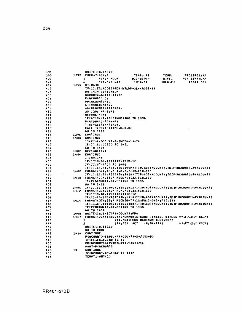
264
l'HI l'1\l "ilO "Ul " 02 H3 40" .. O~ " :It 401 40j-40~
"H' '11 412 U~ 41't US U~ 417 "II! 419 ,,~C
4 ~1 422 ":?3 "2" -:~ "2t. "27 428 42';1 " jc ,,31 U? 4.33 ",H .. 35 "36 "37 4J8 " 3<, , .. C ,,41 442 "43 .... .... ~ .... ,. ""1 H8 H~
'!lO 4~1
"~2 "53 '54
RR401-3/DD
IIll TE C IW.ll92) 1392 FORMAT"lr,' TEMP. A1
1 'Ill,' HOUR "IO-OEPTh ~ "ll,'OF OA' CO~G.F)
139' Hh."::;l8 IFCll.(~.H~38J~TEM:HTt"P-38.(hu38-1' DO 1111~ 12~I,HT("
NCOUH1=J8-CI1-1'·I2 PCHCOUr..,::;O. PPCNCOUHT,:C. ATlM::;HCOUNT·2. AGCNCOUHTJ=A11M/2 ... 00 13'" I(P:h"~ HKP="S-I(P.l IFIA11M.LT.AGlPC .. KP)'GO TO 13'6 PCNCOUH1J=P~CNKPJ
Tl~r=AGlPCNI(P)/2". CALL TI~rVARCTJ"E.O,O,O) &0 TV l~Oii
ll'it. COljl1r,U( IHO COrwTINUf
11:I(I .... r.ICOUrH-2-C .. C~ .. -1 )-2" IFlll.('.~~)GO TO 140~
GO 10 111(" 1402 HC24=NlZ".1 1404 CONIINI.'[
lTI"=II·~ IFCIT1M.GT.IZTITIM=ITIM-12 IF(II.GT.7)~0 10 1406
1 t"P. DIH.
CO(G.F)
PRtsTRESS'1 PER S1IIUO'I
usn '/)
IF C II.U .1. J WR Ill:. CIllo 14 Oll ) 111". AD TC NCCUNY) • TO If'( He OUNT h PC "COU"I , 1408 FOA"AICJ7X.I~.' A."_',Je3I,FIO.l»)
lrCll.l'.7J.~ITEClw,1410)lTI",AOT(NCLUN1'.TOIF(NCOUNT',PCNCOUNT' 141Q FOa"ATC~7X,IS,' NOON',3C3I,FIO.l')
IF(P(hCOU,I'.61.FPA,GO TO 1"45 GO TO 1416
J406 IF'11.Lr.18)V~lTCelw,1412'ITl".AOT'N'OUNT'.TDIF(NCOUNT"peNCOUNT' 1412 FO~"ATC37X,IS,' P.".',3(3I,Fl0.1"
l'elTI".GT.12)ITl"=IT1"'·12 IFell.l~.19'IIAlTE'JW,1414)lTJR,AD'(NCOUN1),TDIF(NCOUNT),P(NCOUNT,
1414 FOA"Ale371,I~" RIDNIIHT',ll,F8.1,2C)I,rlO.1» IFell.GT.l"W~IT(ClW,1401'ITI",ADT(NCOUNT"TOJF(NCOUNT',PCNCOUN" IFCPCNCOUN".6T.FPA)GO TO 1445 60 TO 1416
144S WR1TtClk,1411,PCNCOUNT"FPA 1417 FOkMATCIIIIIHO.21I,'CR.OR,STRAND TENSILt ST.[SS =',F1.2,' KSI'I
1 29.,'EICtEDS R.IIRUR ALLOIIED'I 2 2'1,'S' At! CO.,,,.FPU :",F1.2,' KSI') WRIJEClII,lllU GO 10 2000
1416 CONTINUr PCHCOUNI'=lCOO.·PCNCOUNT).SA/CSS·O) JFCEL.CO.O.'CO TO 10 PPfNCOUNT):,CPCNCOUNT,-PA.,)/CL PAII1=P'NCOUtiU
10 CONTINUE I'CNCOUNT.GT.l'GO TO 1"11 1(MP11=AD1Cl'
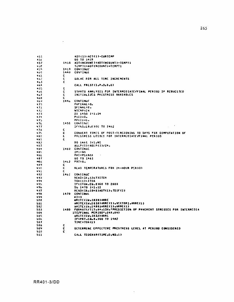
~,.
.~t _57 ";:'1' .~<;
He .&1 u,:, "r:.J .,~
.6~ ~,,~
H,? ",B Hd HO HI , 1~ HJ • H H:, .n on1 us , 7L.. -eo 'Ill _8::> 'BJ • B' _8~
"It "87 -.ee HI9 ,~c
_'H "92 4"f~ U_ ."f!:> 49& .,,7 4911 499 ~oo
501 502 503 50. ~05 )O~
501 508 50'1 510 511
RR401-3/DD
1"18
C C C t 14"b
t C t t
1460
14t2 t t C 141.1
1470
1480
C t C
AOT(1'=AC1Cl'-CURTE"P GO TO 1-19 AOTCNCOUNl':AOTCNCQUNT'-TE"PTl T~MPtl:AOt(~COUNT'.TE"PTl CON11NUC CO"TIHUE
SOLve fOR All TI"E INCRt"ENTS
S1AATS ANAL'SIS FOR INT[RMEDIATE/FINAl PERIOD IF R(QUESTEO INITIALIZES PRESTRESS VARIABLES
CONTI HuE PMF I NAL :0. SfINAl=O. NTEMP::2" DO H!lO 1=1.24 PU,=o • PPCI)::!). tON1IW: Irc~S.L'.D'GC TO 1"2
CONVERT TIMES OF POST-llNSIONING TO O"S FOR COMPUTATION or PRCSlRESS LCSS(S FOR IHt[RMLDJAtr/FINAl PERIOD
00 I_f.C J=l.N!.: ALlPCIJ=AGEPCJJ/2-. COhl lIhUe. IP1:NS PIH=PSUlS) GO '0 1461 PRT=O.
RLAD T["PtRATURtS FON 2_-HOUR P!RIOn
COIU aue READClh,13'7)I10A lOAe U=JTOA IF(ITOl.E~.O)GO TO 2000 OU 1470 1=1,12 RElO(ll,1040)AOTll),TOIFII) COIf'UUI:. leI:" WRITEIIW,1020)ARRE WRIT[IIw,IOlO)ARREfl.,VECTOR1,ARREII. WRITEllk,l.eO)ARRECl.,ARRECl. FOR"ATC/117.A •• lll.·PREOICTIO_ OF PlVE"ENT STRESSES FOR I_T[RREDJA
lTE/FINAl PERIOD',14I,A.) WR1TEfJW.IOl2.AaR( IFCPRT.tO.O.)GO TO 1'82 1I"£=TOA(1)
OETERMINE [FFtC1IVt PRESTRtSS LEVEL AT PERIOD CONSIDERED
265
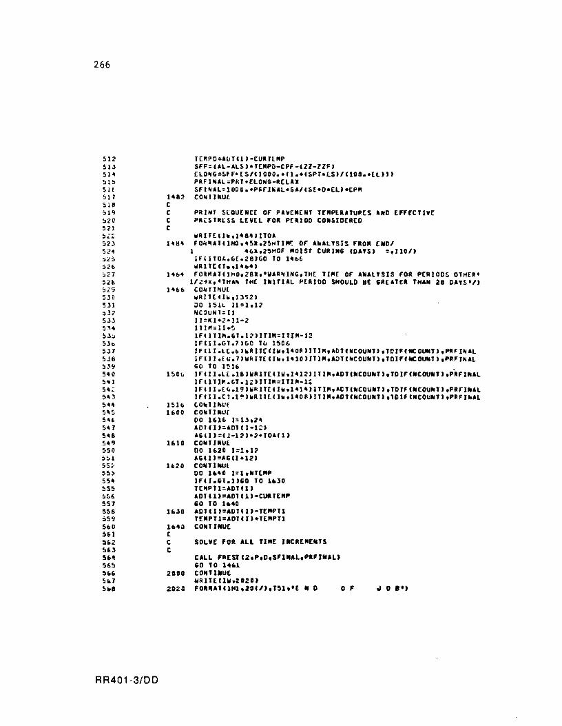
266
512 513 514 !ll::' 5a ~11
51B ~19
52C 521 !),:; 52~ 52<1 ~~!)
:;26 ~21 sn ~;:<;
530 511 :d.? 533 S~~
:'3=> 5lb 537 5.18 5~9 5~0
5'11 54:: :;~ J 5H 5'~ S.E: 5H 548 549 550 ~~l 55., 55~
554 ~55
5!iE. 557 558 559 5(,0 361 51'>2 563 564 565 566 !i&7 5.8
RR401-3/DD
1482 C C C C
l~lb 1600
1610
1620
1630
11140 C C C
2000
2D2O
l[~PD:IOTC1'-CURTl"P SFF:CIL-ILS'-ltMPO-CPF-CII-IIF) [LONG:SfF·ES/CI000.-fl.·CSPT·lSJ/llOO.-lL»' PRFINIL=PRt4ELONG-RELAX SFINIL;loDo.·p~rl~IL-SI/(S~-D·ELJ.CPM CONTINU£.
PRINT SlQUENCE OF PAVEMeNT lCNPlRI1UPES AND £FFCCTlvr PR~STR[SS LEVEL FOR PERIOD CONSID(R[O
WRIT[Cl~.14a4'Il01 FO~~AlClHO.45X,25HtIN! OF A~AL'StS FROM [NDI
I 4~.,25HOF "OIST CURING CDA'S) =,110/, JF(ITO'.G£.28'GO TO 14"" IH\! It: U.,l H • ., FORMllCI~O,28X.'WIRNING,lH[ 11"£ OF ANAL'SIS FOR PCRIODS 01HER' I/ZiX,'1HI~ TH[ INJTIAL PERIOD SHOULD BE &REITER lHAN 28 OA'S'/'
CO"" INUE wRI1tUIo',ll<j2' ;)0 1'51L U=I,12 NCOUNT=11 I J =1( 1*2' 11-2 11 IM=1 l+~ IF(llI~.G1.12'JTIN:ITtM-1~ IFC11.G1.7'GO Tv 15C6 JF(lI.lt.&'~RllCCIW.I~OR)JTIM,IDlfNCOUN1),lCIFfWCOUN1),PRfINIL
IFCJI.f~.7)W~ITEfJw.I~IO't11",AJ1CNCOUN1"10IFfNCOUNl,,PRFI~IL GO TO 1~1b . IFC11.Ll.18'UAl1[llW,1412)ITI~.101CNCOUNT'.10IF'NtOUWT',PRFINIL Jr(lTI~.Gl.I£'J11"=ITI"-14 IFCJI.Ew.19'UkIT[CI_,141',ITIM,ICTCNCOUNT"TOIFCNCOUNT"PRFINIL IFfll.Cl.IQ)wRI1LCI_tI40~'J11",AD1(NCOUN1"lDlFCNCOUNT"PRFlhAL tOh1Jhllf COMl UnJr DO lUr. l:lh2~ IOl,I'=101CI-12' IG'I'=CI-12'-2.'OAf1' CONI INU[ 00 1b20 1=1. 12 UII'=16U-12' COlilIliilUl DO 1.40 l=l,Nl£NP tFlt •• I.I'.O TO 1.30 ltltPT1:AOH 1)
IOTC1'=A01Cl,-CUllENP 60 TO lI.40 10TCI'=ADlll)-TENPTl TE"PTI=AOTCI'·lENPTI CONT INUt
SOLVE fOR ALL TIN£ I_CR[NEN1S
CALL FREStC2,P,D,SFINAL,P.FJNAL' .0 TO 1461 CONTINUE WRll£CUhZ02OJ FOR"A1Cl"I,20C,),151.'[ N 0 0 F .. 0 8"
1 2 3 4 5 6 1 f! ~
1C 11 12 1:5 14 15 U. 17 lIi 1':1 20 21 22 2J 24 25 26 21 26 ,"I 311 31 !:: ,)3
RR401-3/DD
SUBIIOUTINC TITLE e c eteeeeeeeeeeccecceeeceeeeeceececeeeecceceeccceccececeeeeeeeeceeccce c e THIS SUeROUTINE PRINTS tHE PROGRAN TItle t eceecececeeeeeeeeeeeeccceeeccceeeeeeeeeececcececcececceceeceeeeeeee C c
eO""ON/bLOCK4/IR.IW WlIlI((JW.IQ)
10 FO~"AT(IS(/).46 •• 6(·P·).6It5(·e·'.31.6(·P·).61.2(·1·)1 1 46X.7('P').41.7('C').2I,7('P".4I,3('1'" 2 46X.2('P·'.41.2(·P·).21.2(·C·).~X.2('P".4X. 3 ~f·P".21.4('I')1 4 4~ •• 2('P').41.2('P').21.2('e.,,81.2('P').41. 5 2(·P·'.4X.2(·I", 6 461.7(·P',.3X.2(·C').8X.7(·P·'.5.,2('I'" 7 461.£ ('P,,.41.2('e' ).81.6( 'P' '.6-•• 2('1'" 8 46 •• 2(·P·).91.7('C').11.2('P".71.8('I'" 9 461.2(·P".101.5(·C·'.31.2('P".71.8('1'"
wRlTE 11111.21) 20 FOII"ITI4(/).361.551 ••• )/361, •••• 531 •••• /361 ••••• 61 •• I_Il'SJ~·.
1 • OF PRCSTRESSED CONCRETE PIVl"ENTS·.51 •••• /3' •••• ·.J4X. 2 'coNsrVlRING THE INElAS1Ie •• 14 •• • •• /3' •••••• 7 ••• NltuR[ •• :3 • or THE 5lIE-BIS[ FRIeTIa. 'OIlC[5 •• 71 •••• /361 ••••• 13X. 4 "~[RSloH It f£S~UARI 1986'·.141 ••• ·/361.· ••• 531.·.·/361. 5 • ••• 91 •• e'NTER fOR T~'NSPORTITJON R[S[ARCH·.IOI •••• /3fl. 6 '.·.101,·TH[ UNIVERSITY 0' TE.IS AT IUSTIN •• IO •• ·.·/36 •• , ···.531.·.·/361.55(·.·'1
ACTURH
'"0
267
268
1 2 .3 .. 5 (,
1 8 '.II
10 11 12 I! 14 1:It 17 Hi H 2t' 21 22 D 211 2 !:I 2 ... 21 28 2" Je 31 J2 33
"II 35 Jb 37 38 H 110 III 42 43 44 it!)
4b itl lib 4<; 50 51 52 53 5it 5S
RR401-3/00
e e ceceeceeeccceccccccceecccecccccccccccecceeccceccceeeceecccecccceccec e c e c C c e
SU~ROUTINE FREST D£TERMINES THE PRO~lL£S OF FRreTrON RESTRAINT STRLSSES AND PRESTRESS. ACCUMULATED LONGITUDINAL MOYEMENTS AND CURLING STRtSSES AND DEFLECTIONS. FOR ALL TIME INCREMENTS OF T~C prRlOU OF ANALystS eON~JDER(o. THE FRICTION SUSMOCELS fOR THE INTERYALS OF [ONTkACTION/EXPANSION IND THE MOvrMENT REVERSAL INTERVALS. ARE lNTE&RATED IN THIS SUBROUTINE.
c cccccceccecctcccccccceceeceeccceccccccccccccecccccecccececceceecce[ccc c c [ [
c. c c [
c c [
t C [
[
C. t C. [ [
c c. c c c c c [
[
c c c c [ [ [
c c [
IlARueu:s:
XCI) Fun
STFl(IJ
IANHI)
DELT IZ
ppcu
Sff"
NEL
llU
RATIO
= COORDINATE ALONG SLA8 LENGTH OF POlNT I CFT) : AYERAGE STRESS IN ELEMENT I 'PSI' = ST~AIN THIT ELEMENT I TEN~! TO DEY!LOP AT TIM[
INCREMENT CONSIOERED (IN/IN' = INITIAL CO~OllION FOR MOYEMENTS OF POINT I. FROM WHI[H
FURTH(R MOVEMENTS OF THE POINT ARE COMPUTED CIN, : AGE SINCE THr. CUkl~G HOUR FOR THE TIM[ INCREMENT COhSIDERE~
CHOURU = TEM~[RATUR£ CHANG~ FOP Tl"E INCREMENT CONSIDERED CDEG.F) = STR'IN IN[REMCNT OF SLAB fLE~£NTS DUE TO SHRINKAGE F~R Tl"(
INCREMENT CONSIDERED (1N/IN' : STRA1N INCREMENT our to PRESTRESS APPLICATION DURING TIM(
INCRCMENT CONSIDERED (IN/IN) = tOTAL S'RAIN INCRE"t~T OF SLAB [LEMENTS FOR TI"E INCREMEhT CO~SIOER£O CI~/IN'
: INITIAL ELEMENT FOR S£G"ENT EXPERICNCING MOVEMtNT CSEGMENT 2 IN FRICTION SU8MODEL
: TOTAL MOYEMthT E.~ER1tN[[D 8Y POINT I AT CONSIDERED UN'
A REVERSAL OF 2' l1"E INCUMENT
= RATIO BETWEEN TH( NORM OF THE CHANGE OF MOVEMENTS OF TH[ SLAB POINTS BETWEEN SUCCESSIVE ITERATIONS. AND THE NORM OF TH[ "OVEMENTS AT THE LAST IT[RATION
ZO = UNRESTRAINED MAIIMUM CURLING FOR TIM£ I~CR[MENT CONSIGEREO CIN'
SO : FULLY RrSTRAINtD CURLING STRESS FOR THE TIME INCRCMENT CONSID(R(D CPSI)
UCU ZX
= AYERAGE FRICTION COEFFICIENT UNDCR ELEMtNT I = FINAL MOVEMENT OF GIVEN SLAB POINT AT TIM£ INCREMENT CONSIDERED CIN)
f = AVERAGE PRESTRESS PLUS FRICTION I(STIAINT SLA& ELEMENT AT TI"£ INCREMENT CONSIDERED
: CURLING DEFLECTION OF 81'tN SLAB POINT AT CONSIDERED elN'
ZFI
STIESS FOR GIVEN CPSI) TIME INCREMENT
ST = CURLING STRtS. AT BOTTOM OF SLAB OF 'I'EN SLAB POINT AT TIME INCREMENT CONSIDERtD CPSI)
C tcccCCCCCCCCCCCCCCCCCCCCCCCCCCtCCCCCCCCCCCCCCCCtccctccCectcccCCcccccccccce C
£>"' £>5 Ell> £>1 L8 ~'3
n 71 1;; 1.1 H 1~ 1t 71 7b 7'1 bO 81 8:: 83 84 8~
8/, 87 118 89 90 91 92 93 94 9~
9b 97 9f' '39
100 101 102 103 10" 105 lOb 107 loe 109 110 111 112
RR401-3/00
C e
e e e
U.O
IH.
e C e C
120
C C t
110 C C C C
132 C C t C C
COMMON IBLoeK3/Ml.lU(20),UUC20) COMMON IBLoeK4/1R,JW CONP-ON I8LOCK~/KI,CURTENP.AG(100),AOT(100),TDIF(100),PP(lOD) COMMON IBLOCkh/G.eONPF.ALT01,lTOT,CR£EP,PA,SK,SL CO"NON IBLOCK1/OL,NILO,NT£"P,TOL.N"11 COMMON IbLOCKI/IL,EL.lZ.SA,$S,PSCI0"AGEPCI0) CONNON IBLOCK"N.l(200),U(200) COMNO~ IBLoeKIO/Z1(200".(200"F.C200"STFI'200' CO"NO~ IBLOCKI2/ToaCI0) CONNON IBLOCKIl/CPF.CPM,ZZF.RELAJ,FPY OJ"tNSJCN Z2(200).ZIN1C200),P(100)
DEFINE LE~GT" or SLAe ELENENTS AND INITIALllE PARAMETERS
OI=OL/NILC IN=NILC/2. IFC(IN-IFIJ(IN».EQ.O.)GO TO 100 1(2'=01/2. IN:NlLO/2.·1.5 M:AM KI:3 6C1 TO no M=NIL0I2·1 Kl=2 CO .. lINU[ N2:M-I
INItiALIZE TO lERO THE VARIlBLES FOk STRESS INC STRAIN OF ThE EL£M£~TS (r. ANC ~Trl'
00 120 I=ltM2 F IC I) =lI. STFI C 11=0. CO"T IHUE FXCM)=fI. xu '=0. un )=D.
DEFINE COORDINATES OF NODES BOUNDING THE ELENENTS
DO 130 1=«1." XCI ,=xe 1-1 '.01 CON1I11U£
INITIALllE TO ZERO THE VARIABLES REPRESE.TING New INITllL CONDITION FOR "OVENtNTS, DEFI.ED AT THE LIST REVERSAL OF ""VtNENTS CZINT)
DO 132 12=l,N ZANTCl2':0.
INITIALIZE '0 lERO VlRllBLE REPR[SIN'I.' INCRERE.T IN ROVE"E.T OF ENO POINT OF St'"EN' I ezz, BETWEEN SUCCESSIVE 1'£RlTIONS IT "OVERt .. , REVERSlL I.TERVlL
ZZ=O.
269
270
ILl 114 11!J 11& 117 lH 11'1 120 121 12Z Ie 3 124 12!: 121> 1.;:7 128 129 130 131 13" 133 lH 13:: 13(, 131 131> 1l'i HO 141 14Z H:' 144 H5 h6 141 141 H~
1:.0 151 1:'12 1 ~J 15' 1!l!l 1St. 1!'11 lS8 159 160 161 162 If..) 160" 16S 1" 161 168 169
RR401-3/DD
t C C C
c C C C
2;)
C C C C
c c c C
142
C C C 144
c C C C
C C
TEI4P r:CUIl TEMP IN0111:'0 lNOPP=1I Nt2":.1
SOLVE FOR D£FORMAtl0N~ 'NO ~TRE~S£S FO~ ALL T£MPERATURES OF TH~ ANALYSIS PE~IOO CON~IDlR£~. AT 2-"OUII INTERVALS
00 140 1=I.NtCMP N£.L =0 INOCO .. :.O ZY:.lZ IH'E=AGCU DEL 1 ;.AlIT U , 1CNPT=TEMPt·OCLT
DETCRMINl ELASTIC MODULUS AND SHRINK.6r. STIIAIN OF CONCIIET£ FOR THE lIME INTeRVAL CONSlueREO
CALL Tl~(VARC1JM(.D,IP1,O' ll;;.Zl-ll IF(~K.t,.l'GO TO 2~ IFCI.GT.I.ANO.I.lE.12,ll=O. CO~t INut:
OE1~~Ml~£ S111AIN INCIIE"[NI FOR SlA6 ELE"ENtS IN TIMf INCREMENT COtoSIOt lIED
SlF:AloCCLT-Zl-PPlI'
O[TER"I~t IF STAAIN INCR£Mr~1 LEADS TO • MOV£MCNT REVEIISAL AND DCFINE SlkAINS OF EltME .. TS FOR ANALYSIS
DO 148 11=1."2 FP~O"=tf.(IJ·1)·F.(II"/2. IFtSTF.6£.0 •• AND.FPROM.LE.O.'60 TO 146 IFCSTF.Lt.O •• AND.FPROM.6t.O.'GO TO 146 FAUX:SIF-FPIIOM/EL IFCFPIIOM.GT.O.'GO TO 142 IFfFAUX.'T.O.'60 to 14' CiO TO 144 CONTINUE IfCFAua.L1.a.)60 to l'~
SLAB IN A AOV£"ENT-lEV[RSAl INTEl VAL
CD'" ,NUE IFCNEL.NE.O,GO 10 1'~
DEFINE INITIAL ELEMENT OF StSMENT 2 I£'EISI.' "OVEME.' IF IT HAS NOT BEEN DEFINED B£FORE
NEL=1l INi:L=NEl·l 'FCNCL.£8.1'INEl=1
170 171 172 113 17'10 175 lH 171 171' IH lSI,) 181 18'< 183 1&4 l!1~
l!H 181 188 189 1"0 1 \/1 132 lJJ 1'34 H5 1 \It 1 '77 198 19" 200 201 202 203 20~ 205 20t. 201 208 209 210 211 212 213 214 US 210 217 218 219 220 221 222 223 224 22~
226
RR401-3/DD
C
14 C C C 14!l
11 3 C C C C
2
c C C
l~O
C C C
C C C
c C C
If.O 110 180
00 14 I2:INEL.N 1ANTCI2':12C12'
STFIUl'::I' AUX U;)lK=1 .0 TO Ita
DEFINE STRAIN OF ELE"ENlS IN CONTRACTION/EX'.NSION rNT£RVAl OR THAT 00 ~OT REVERSE "DWENEhT IN "OV£"ENT-REVERSAl INTERVAL
SlFICIl':STFlCII'.STF CONt I hU r
I'CINOIK.!'.I.ANO.N£l.lE.I'60 TO 3 GO to 2 JNOPP=O CON1INUt
DEFINE ~E~ INITIAL CONDITION FCR All [LENENIS C"JVEMEhT-R(YtRSAL INtERYAL CO",LETED)
00 " 12=101'1 U'oU I;:J=Z~ 112' INC}K:(; CONIINUt IFC_EL.Lt.ltGO TO 190
NN=O 11=0. IUL1=ZCtfELJ SJ1::S1 SU"I:0. $uI'I2=O.
SOLvE FOR S['"ENT 2
'ALL IlrRC1J.SIl.NCL.".O.INDCONJ SI):FICN£U
SOLVE FOR SE'"ENT I
CON'UTE RIT10 FOI SUCCESSIVE ITERATIONS
DO 180 11=2," Z":IUll I'Cll.&'.NEL'GO '0 160 ZCll,=IICJIJ·ZA.1Cll' '0 TO 110 Z(ll'=ZI(ll'.ZI.'(ll'.ZI SUN1=SU"I·CZ"-ZCll"*CZ,,-ZCIIJJ SUN2=SUM2+Z(JIJ*ZCll'
271
272
:!27 22& 22"1 2lJ 231 232 ,~3
2.H ~3J
2J!> 237 238 2)';
240 2H <'41 H! ,44 Z4:;' 241;> ~47
24& 24~
Z!,!I 2~1
2~2 25) 254 2;,!: 25b 251 2!iS 2!t~ 2Eo!. 2f>1 Cf,2 21>3 2.,4 2 Eo!. :Eot 2b7 2&11 2&9 270 211 212 273 2H 21'!) 2110 27J 278 219 280 21!1 282 28l
RR401-3/DD
C C C 190
C C C
195 200
al 202 C C C
21('
212
C C
215 21 ..
lD 1
~'TI0~SQRT'SUM1/SU"2' If'~'TIC.ll.TCL'GO TO 200 Zl=O.10·'l(~£L)-ZULT'.0.90·'I NN:.IIt".1 If(IIt~.lr.NM'X)GO TO 150 INOCOIlt=1 GO TO 200
SLAB IN CONTRACTION/exPANSION INTERVAL
CONTI Nut C'~L ITlRCO •• SI.l .... 0,INOCO,.,
OEflNt MOVrM£NT OF NODES
00 195 11=1," ZCfl':ll(ll).21,.T(11' CO,. TINUl IFCNEl.lE.I1GO TO 202 IfCPPCIJ.Nl.O.'GO TO 201 GO TO 212 I N!)PP:l CO"lUlu~
DO 210 12=I.M 22(12'=1«12' CO'illNUt 2Z=2Z.ZY I H.MP:.I If'l.l£.12.aNO.KK.NE.IJ'O Te 140
PRINT HEaDINGS aND ltSUlT!
IF(KK.rC.IJGO TO 214 I TE'''P:l TrMP-12 11=IU.,,·1-26 GO TO 21£. II=KI·2·!-2-CNC24-1J·24 IfClf.£Q.25J60 TO 215 100 TO 2110, NC2t:NC2t'l lO=Cl.·PR,.AlTOT·TOIF(rTC"p,·($L··2.0"0 SO:(CL.AlTOT·TOJFCrTC"p'/C2,·Cl.-PR')' JTI"=t1'5 IFC11IM.GT.12)lTI":lTI"-lZ IF(11.6'.J'60 10 10 IF(II.Ll.'JWRI't'IW.~'JTI" FOR"AT(lHl.24.,lHHOUR : ,15,' A.".'/) IFCII.CQ.1)WRIT£ClW.6'lll" FOlMATCIH1,24 •• 1HHOUR : .15.' NOON'/) GO TO 50 IFIII.LE.18'WRITE(lw,lJITJ" FOR"AT(lHl,24.,lHHOUR ~ .15,' P.".'/) IFCJTI".GT.12JJTJ"=rlIM-12 IFCll.['.1~'WRI1ECIW,'JITI"
284 c8!) 28t> 21H 288 289 2'10 2 'il c92 2'13 294 29S. Z9f, 297 291! £'\'9 lOO 301 3D~
303 l04 3D! 30E. JOT l08 309 31Q 311 312 Jll J14 ll:! ll"& .H7 JIB 319 320 321 322 323 324 325 326 l27 328 J29 330 331 Jl2 333 334
RR401-3/DD
8 FORMAICIHl,2_X,7HHOUR = ,IS,' MIDNIGHT") IF(II.Gl.19)WRlIECI~,~)IIIM
:!O CONI I Nue NG!l5=MJ!>6·1 DO lID Jl:1,NG~5 IFCll.lG.I"O TO 51
1000 WR'I[CIW,lO;' 3V2 FORMUUHl/23X,' COORDINAtES NOWt:M£n eO(FF OF FItlCTlOfoi PRE:
ISI.FRICI CURLING 80T.CURlJN"/23X,'FROM "IDSLAeCFT' C 21N) SIRESS CPSI) DEFLECTION'IN) STRESSCPSI,' 3IJ
60 10 304 !II COt,tUhUi..
WRllEU .. ,314J l14 FORMATC~4X,' COORDINATES "OVEMENT COEFF OF FRICTION PREst.F
.Rlel CURLING BOf.CURlINb'/23X,'FROM "IDSLAefF1) CI~' • ST~LSS CPSI' DEFL£CTIO.CI~) SlRt:SSCPSI"'J
304 NELE=55
C
JF(11.('.NG55)N(Lt:=M-55+'NG~5-1' 00 lID 12=l,NELl NCOUNT=~5+CI1-1)·12
C COMPUIE CURLING STRESSES C
1K=0. SKO=O. TOF:IDIFH Tt/IIP) lINe= X 'NCOUN T' CUL eOIlLl TOF, XNC ,.ZI(, SKU 1FI=10+ZI< SY=SO+~I\O
IF(PRFINAl.EG.O.)'O TO 309 lX=lCNCOUNT'-SFlfolAL+xeNCOUNI)·12. F=~XCNCCU~T)-1000.·PRFINAL·SA/(SS·D) &0 10 311
30~ 1X=leNCOUNI' F=" XC 1ilC0UN' ) -P C 1J
311 IFeNCOUNI.£O.1)FPLOT=~ 313 WRIT£ UII, 320UCNCOUNH .ZIl,ueNCOUNThF,zn.n 320 FOk"AIC20X.F15.2.2F15.5.FI5.2,F1S.5,Fl~.Z)
C
IFCINOCON.£O.I'GO 10 330 60 '0 140
C PRINT M(SSAGt AT tND OF 1T£RATIONS C 330 wRITEel~.350) 3S0 FORNATCII/1HO.28X,'CONVERltNCt NOT ACHItVEO; Al50R1TH""
1 29X,'STOPP£D FOR "AXI~UM NO. Of ITtRATIONS" 1_0 WRII£C07 •• )ZX.fPLOT
RETURh tNO
273

274
RR401-3/DD
30 C C C C
K"'"'-I·NEL UCK+l'=CUCK+l'+UCK)'/2. FICK'=F.,k+l'+UCK+l)·'·tICK+l'-ICk"/144. CONT INUE
OETERIII~~ RESTRAIN[O "OV(ME~TS Of NOOES ANe COMPUTE ~ATIO fOR $UCCtSSlv~ ITtRATJONS
00 40 1:IN.IIT IM=Z1CJ ) fPIlO"=Cf.C I '.fllCl-B '/2. D"Ov=SlfICJ-l'+FPROM/El lICI'=C.6~·CZlCI-1)·0M0v·CllCI'-.'1-I"·1'.).O.l5·11tJ' SU~I=SU"1+tl"·ZICI"·ClM-Z1CJ)) SU~2:SU~2+l1CI).lJCI)
CO"" I NUL IlATJO=~ORTCSU"I/SUM2) IFt~A'10.L'.TOL)&0 TO ~o NN=",I\I+) IFC~N.lr.NMA."O TO 2a "M=l'ilLO/2~1 IF(NEL.EO.I.l~O.MT.[Q.MM)£O 10 4: GO TO !.l' cor" l~uL .
MAKr S.ITtH VARIAbLE I~DCON=1 If SLAB IS IN CONTMACTI0N/llPANSION INT[RVAl
IHOCOH=' COIIIUNUf. RC::TURN tNO
1 2 3
" Eo 1 8 'J
lU 11 1,' l~
1'4 I!:. If:: 11 16 1<;
21
RR401-3/DD
c c: CCCCCCCCCCCCCCCCCCCCCCCCCCCCCCCCCCCCCCCCCCCCCCCCCCCCCCCCCCCCCCCCCC c: c: c: c
SUBROUtINE TJOtVAR O£TE:RI"lNU EStllIIATES OF CONCRE:H ELASTIC "OOULU~. RAOIUS OF RELATIVl STIFFNESS OF THE SLAb. SHRI~KA6t. CREEP ANL RELA.ATION Of THE: STEEL ST~AHOS.
C CCCCCCCCCCCCCCCCCCCCCCCCCCCCCCCCCCCCCCCCCCCCCCCCCCCCCCCCCCCCCCCCCCC c r. t C c: C C C C C C C C C C C c r. C
\/AI\IAtlL£S:
LL !.L 12
CPI
RelU
: TIIII( OF EVALUATIOh SINCE CURING (DAYS) : CONCRCTE: COIIIPKESSIVl STRthGTH AT TIIII(
or (VALUATION (PSI) = CO~CR(T( ELASTIC IIIODULUS AT TIlllf Of (VALUATION (Pst) = RADIUS OF RELATIVE STIFFNESS (IN) : SHRINKAGE STRAIh AT TIIII£ Of [VAlUAT~ON eIN/IN) ; (REtP SlRIIN (rOR (VALUAIION Of PReSTRESS lOSSeS)
ey THE TIllll OF [VALUITIO~. SINcr APPLICATION OF LASl PRESTRESS FORCE (IN/IN'
; TCTAL tREEP STRtlH fY Tht TIlliE OF [VALU'TIO~t SI~CE ArPLICATION OF FIRST PRESTRESS fORCE (IN/tN'
= TOTAL STEEL RELAXATIOh bY TH( TIlliE Of EVALUATION (P[I,CEN1)
= SHRINKAGE STRAIN (fOR [VALUATION Of PRESTR(SS LOSSES) PY THE TIIII[ OF EVALUATIOh. SINCE APPLICATION OF LASl PRESTRCSS fOPCE etN/IN'
c CCCCCCCCCCCClCCCCCCCCCCCCCCCCCCCCCCCCCCCCCCCCCCCCCCCCCCCCCCCCCCCCCCCCCC C C
C
Dl"~NSlOH CREPCIO.IO) CO~"ON/bLOCk./G.CO"PF.1LTOT.ITOT.C'fEP.PA.SK.Sl CO~"OHIUlOCK8/Al,Et.lltSltSS.PS(10).AGLPClC' CO~"O~/~lOCK13/CPf.CP".ZZf.RlLAXtfPT
C DefINE CONCRETE PROP(RTIES INOEPlkDt_T or PRESTRESS FORCE C
70 80
C C C
CAll CO"PSTR(TIME.COMSTR' tl:33.·CGe·l.5'e$QR"CO~STR)
Sl=CCEleDe·3.0'/C12. e Cl-PReeZ.G,eS&),·eO.25 IFCTIMl.lT.1./3000.'GO TO 70 AL:1LTOT &0 TO 8tI AL:Cl.-9.e(1./3.-TIME)ee2.'·AtTOT $HRN=2~.e[Xp(O.36eD' lZ=CTIMf/CSHRH.TIME)'.lTOT IFCINOICA.EQ.O'GO TO 200
D[FlkE PAKA"ETERS DEPENDENT O. AIIIOUNT Of PRESTAESS fORCE
275
276
~6 57 56 59 &0 1.1
63 b~
6:&£ bl f>8 (,.,
70 11 7? n 7. n 7t-77 78 7; 110 U 8" 83 6" 8~
8e. 87 88
'8'" 90 91
RR401-3/DD
112 113
115 120
125 C C C C
200
DO 120 ll=l,IPI DP=PSClU-PAP.T lI"P=AGlPC 11' tALL tO~PSTRCTIMP,CO"' (p=J3.eCG·el.~'·SQRTCCO"' STl=1000.·0PeSA/eSs·O·£P, CRA=O. DO 115 12=ll,IPl IFCI2.lG.IPl'60 TO 112 TI~=A6lPcI2·1'·A'EPCll) GO to 113 tIM=tIMl-AGlPcll' CON1 nor CRAUX=11M.·0.6 CR='CRAUX·CREEP.S1I)/CI0.·C~AUX)
tR~PCJ2.U'=CR-CAA tPM=tPM·ClEP(12,ll' tRA=CR COrHlf'Ul PANT :PS ell' cpr=o. 00 125 11=I,IPl CPF=CPf.CA£PCIPl,Il' CON TlNU(
DEFINr AMOUNtS OF SHRI_KAGE AT THE Tl"l OF STReSSING AN~ STRANO RELAXATION
Tl"=C1IME-AGEPeJP1"·24. RAUX=P~CIP1)/fPT-O.55 JFtRAUX.Ll.C.)AAUX=O. RCLAX=CCALOGI0(TIM,/I0.'.RAUX).PSCJP1' lZF:'AG[PCIP1)/(SHRN.A,rpCIP1)"·ZTOT CONflNUl !t[TURN END
1 :2 3 4 5 ~
1 I> 9
1C 11 12 D 14 1:' 16 17 16 1'1 2(;
21 22 23 24 2~ 2b 27 28 i::<t 31.1 31 ~2 33 ,H l~ Jt. 37 31> 3., H 41 44 43 ... ,,~
4t. H 48 49 ~G 51 ~2 ~J ~~
5~
RR401-3/DD
277
e e eeceeeeceeccececceeccccccccecceccccceccccccccceccccccecccccccccc c e e e e
SUBROUTIN[ FRIC COMPUTES FRICTION COEFfICIENTS FROM MOVEMEhTS OF THE SLAB NODES. INfORMATION FROM THIS ROUTINl IS USED IN SUBROUTINE ITER TO OETERMINE THE PMOFlLES Of fRICTION RESTRAINT STRESSES.
THE sus-
e ccceeeeceeeecccecccccccceeecceccceecceeccccccecccccccecccccccccc c c c c c c c c :: c c
"1 :. NO. Of POINTS IN ,~( SUPPLJE~ FRICTION COEfFICIENT ~S. OISPLAC~"(_T REL"IONSHIP. "OREOVER. "I IS A CONTROL VARIABLE INDICATING THE TYPE OF REL.TIONSHIP: If M1=1. T~E R~LATIONSHIP IS • STRAIGTH LINE. IF "1=2. T~E RSL'TIOhSHIP IS AN EXPOhENTIAL RELATIONSHIP, If "l>Z. T~E RELATIONSHIP IS , MULTILINEAR CURVE.
ZAUI = AbSOLUTE V'LUE CF TH~ DISPLACEMENT llel) OF POINT I CIN) UCI) = fRICTION cO~ffleIENT UNCER POINT I
c ccceccecceeecceccccccccccceccccccccccccceccccccccccccccccccccccccccccc e c
OI"ENSIO~ Zl(200) CO~"ON 16l0CK3/Ml,ZU'2~).UU'20) eO~"ON IbLOCK~/M.Z(200 •• U'200) IFC"1.r~.1)60 TO 10 If'MI.E~.2)GO 10 80 IF(MI.GT.~)GO TO 2a
10 eOlO'INUf "2:2 GO TO 30
20 CONTINUE M2:.Ml
30 CONTINUE C C COMPUTt FRICTION COEFFICIENTS FROM STRAIGTH LINE OR FIOM MULTILINeAR C CURve C
00 " l1:ti1EL •• n ZAUI:.A6S(llll1 )) DO !l0 .I=hM2 .11=.1 IfeZAUI.LT.ZU'J"60 TO 60
~o CONT Uwt U(I1'=uu,,'2' GO 10 70 .
&0 SLOPt=IOOCJ1'-UUCJ1-1"/CZUe.ll)-ZU(Jl-1» UCI1'=UUe.l1-1'+SLOPC·CZAUI-ZUCJ1-1')
70 CONTINUE lr«Z1(ll'.G'.8.,uell'=-U(11'
40 CONTINUE
278
RR401-3/DD
80 C C C
100
90 95 1111
60 fO 110 COllfl .. uE
00 ,~ I1=HtL,1n lAUI=.BS ell e 11 J, IFCZ.UX.Lf.lU(2)'60 fO 100 UCl1J=UUC2 J 100 TO 90 PIUX=lZIUlIZU(2»)··0.ll33 UlIIJ:PIUX.UU(2) rFlZl(11).Gl.0.JUCll):-UCllJ co,n INt..l Rt:TuRN [110
1 2 3 .. !I I> 7 8 ..,
10 11 12 1~
1-1~
11. 17 18 19 211 21 2:1 23 24 2~
26 27 28 2'1 30 31
'32 33 34 3!1 31> 37 38 3<; U 41 .2 .3 4. 4!) 46 n 48 4'1 50 51 52 53 5-55
RR401-3/DD
e e eeeeeeceeeeccceecececttettctcteeeeeceeecccceececceecccccceceeceeccc C C C
SUBROUliNE COMP COMPUTES COMPR[SSIVr STREN6TH OF CONCRLlE AT SPECIFIED TIMES
C eccccccccceeccccccCCCcCtcCtCCtCCtCtCCttCCtcCCccCCCctcCCCtCtctttcccc c c c c c c c c
URUBUS:
TIM( CO"PF
PER CO" COMSTR
= TIM( OF tVAlUATION SINCE CURING COl'S) =:. FINIL COMPRESSIVE STRENGTM ,PSI' = P(RCtNT OF THr FINAL COMPF.ESSIV( STRENGTH = COMPMESSIVE STRENGTH [VAlUATro CPSI'
ccccccccccceeccccccccccccccccccccccccccceccccccececetececce ecce ecce c c
e
OI~[NSION ~[RCENJCS"AGE'S) CO~MDN/BloeK2/KK,AG(UC2G'.rOMPC20' CO~MON/BlOCK~/G.COMPF.ALTOJ.lTOT,CRE[P.PR,SK.SL OlTA l'E/O •• 1.,3.,5.,1.,I'.,21."S./ DATI PERCENT/O.,lS.,3S.,53.,,.3.,82., •••• 100./ IFCKK.Gl.O'GO TO 30
c COMPUTE COMPRESSIVE STRrNCTM IF C THERt IS NO USeR-SUPPLIED RCllTIONSHlP c
00 10 l=l,S .1=1 IFCTIME.lE.IGECI"GO TO 20
III eONTINu£ tD"STR=COI'IPF 60 TO 60
20 PEReDM=CPERCENTC.J'-P[RC(NTC~-1"/CA'ECJ'-I6EC.J-l"
c
PEReOM=PERC(NTC.J-l'·PERCO"'CTIME-I6rr~-J" COMSTR=PERCOM-tOMPF/JOO. SO TO toO
c COMPUTe COMPRESSIVE STRelllSTH IF C THEAt IS I USER-SUPPLIED 'ElITIONSHIP e 3D COUI"C
DO 40 J:hll. .. =1 1,.'IM£.LL.IGtvcl"GO TO ~o
.0 COlli TI IIIUE CO"S JR=eOflPf SO 10 60
50 SLoPt=ccOflPC"'-COMPC~J"/IGEUC".-I'EVC"-J" CONSI.=COMP(~-l'·SLOP£·(II"E-IGEU'''-I'.
60 COIIIT JIIIVE A£TUAIII
279
280
1 2 3 .. 6 1 8 <:
10 11 12 13 14 1~
If: 17 III 1'; 2V 21 2; ZJ 2" 2~
a 27 2b 29 30 31 32 33
''I J~
lEo 31
RR401-3/00
SUBROUTINf CURL(1~.X,ZK.SKO) c e eceeccceecccccCCcttccceecececeecececeeeccccecceeccceeeeceeeeecececcc e e e e
SU8ROUTINt CURL eOMPU1ES eU~LIN~ STRtSSES A~D OEFltCtlONS
ecceceeeeeecceteecceeeeeeeeceeeccceceeceeceeeeeececeeeeeceeeecceceee e e e e t c e e e e
VARUBLES:
Y = eOORCINATE MEASUR[O FROM THE SlAa (NC, or NODE LOCATED AT COORDiNATE X FROM 1H[ MID-SLA8 (INa
ZK = PtRCl~l DtFlEC110N FOR NOO[ LOCATED A DISTANCt x FRO~ MIO-SlAa. WITH R"SPEe1 TO THE MAXI"U~ OEFLECTION AT 1HC SlAII END
SK'l = PtPcE~T STRtSS FOR NODE Loe'T[e A Dlt1ANCE X FROM MIO-SLIB. ~11H RtSPtC1 1v 1H[ MAXIMUM STR£SS A1 MIDSLAe
c ecceceeeeceecceceeceeceeeeccecetcececcccccececccececccceeeecccceeccececcc c e
e
COMMON IBLOeK6'G.FPC.ILT01.1101.S1RNMJl.P'.SK.~L eO""ON 'BLDCK1/~L,NILO.NT["P.TCL.~"IX Y=,Oll.:.-II)*12. YIV.=(Y/(1.414Z·SL" EX=EIIPt -uuu
c O[TCRM1~[. DEFL[CTION A~U STRESS P[RCENTA&ES WITH R~SP[e1 e TO "AXJMU~ VALUES IT THC llG[ AND MIDSLAS RCSPECTIVELY FOR e All eOORDINATt~ eON~IOE~ED e
ZK=-1.4J4Z*COSCYAUX+O.78S4,·CX SKO:(1.-1.414Z·SIN(YIUX.O.78S4,·C •• RETURN UfO

APPENDIXE
JOINT OPENING DATA USED IN THE REGRESSION ANALYSIS IN CHAPTER 7
FOR EVAlUArlNG CONCRETE THERMAL COEFACIENT AND ULTIMATE
CREEP AND SHRINKAGE STRAINS

!!!!!!!!!!!!!!!!!!!"#$%!&'()!*)&+',)%!'-!$-.)-.$/-'++0!1+'-2!&'()!$-!.#)!/*$($-'+3!
44!5"6!7$1*'*0!8$($.$9'.$/-!")':!
283
Movements Movements Temperature Age Joints 2-9 Joints 11-16
(Deg. C) (Days) ( in. ) (in. )
27.0 0 0.000000 27.0 5 0.600000 15.0 6 0.917500 27.0 6 0.655000 22.5 7 0.725000 24.5 7 0.700000 30.0 13 0.735000 30.0 17 0.757500 29.5 34 0.820000 20.0 48 0.967500 13.0 57 1.107500 15.0 58 1.075000 2.0 74 1.347500
15.0 1 0.225000 27.0 1 0.135000 22.5 2 0.278333 24.5 2 0.270000 30.0 8 0.396666 30.0 12 0.425000 29.5 29 0.498333 -
20.0 43 0.683333 13.0 52 0.826666 15.0 53 0.800000
2.0 69 1. 083333 27.0 0 0.155000 22.5 1 0.297500 24.5 1 0.297500 30.0 7 0.520000 30.0 11 0.577500 29.5 28 0.670000 20.0 42 0.862500 13.0 47 0.955000 15.0 52 0.980000
2.0 68 1.275000 30.0 4 0.090000 29.5 21 0.170000 20.0 35 0.355000 13.0 44 0.495000 15.0 45 0.475000
2.0 61 0.760000 30.0 4 0.946666 29.5 21 1.368333 20.0 35 1.740000
284
Temperature (Deg. C)
13.0 15.0
2.0 29.5 20.0 13.0 15.0
2.0
Age (Days)
44 45 61 17 31 40 41 57
Movements Joints 2-9
( in. )
Movements Joints 11-16
(in. )
1. 948333 1.986666 2.436666 1.238333 1. 615000 1.806666 1.806666 2.331666