behaviour of accc uls oslo conductor under heavy …performance against equivalent aaac and acsr...
TRANSCRIPT
Brian Wareing.Tech Ltd Rosewood Cottage, Vounog Hill, Penyffordd, Chester, CH4 0EZ Tel: +44 (0)1244 550578 Mobile +44 (0)7976 123 738 e-mail: [email protected]
Brian Wareing.Tech
Company No: 04347690
BEHAVIOUR OF ACCC ULS OSLO CONDUCTOR UNDER HEAVY ICE LOADS
Dr Brian Wareing
Report No: BWTR_159
January, 2013
For
CTC Global
Contact: Eric Bosze

Behaviour of ACCC ULS OSLO conductor under heavy ice loads BWTR_159
2
Contents 1 Introduction ................................................................................................................... 4 1.1 Background ........................................................................................................... 4 1.2 Site history of ACCC tests ..................................................................................... 4
2 Scope ............................................................................................................................ 4 2.1 Purpose of tests ..................................................................................................... 4 2.2 Report layout ......................................................................................................... 5 2.3 Abbreviations ......................................................................................................... 5
3 The Deadwater Fell Test Site ........................................................................................ 5 4 Test procedure .............................................................................................................. 7 4.1 ACCC Conductors under test ................................................................................ 7 4.2 Comparison conductors under test ........................................................................ 7 4.3 Vibration tests ........................................................................................................ 8 4.4 Ice load tests ......................................................................................................... 8
5 Results .......................................................................................................................... 9 5.1 Vibration ................................................................................................................ 9 5.2 Ice loads .............................................................................................................. 10
6 Summary ..................................................................................................................... 13 Appendix 1 .......................................................................................................................... 14
ULS Oslo datasheet ........................................................................................................ 14 Appendix 2 .......................................................................................................................... 15
Deadwater Fell ................................................................................................................ 15

Behaviour of ACCC ULS OSLO conductor under heavy ice loads BWTR_159
3
EXECUTIVE SUMMARY
SUMMARY
ACCC conductors have been tested at EA Technology’s severe weather test site at Deadwater Fell in the UK for several years. The aim was to provide a test bed for conductor behaviour in terms of vibration, erection techniques and performance under severe wind and heavy ice loads and to compare this performance against equivalent AAAC and ACSR conductors. The CTC Global ACCC conductor ‘Lisbon’ was first tested at the site six years ago. After the initial ice load and vibration tests a new version with a stronger core was produced and re-named ‘Oslo’. Recent concerns over the performance of ACCC conductors under ice load led to a further development to a ULS (ultra low sag) Oslo which had the core elastic modulus increased from 116 to147 kN/mm² and a tensile strength increased from 2.16 to 2.59 kN/mm². The core modulus change alone was intended to reduce sags under ice load. This low sag characteristic of the ULS Oslo conductor is aimed at countries where wind and ice loads are common. As a result of past tests at Deadwater and the improved characteristics of ACCC conductors after ‘load shift’ had occurred, the ULS Oslo was erected at a tension intended to produce a fully load-shifted conductor at erection. This report shows vibration data for the Lisbon ACCC (same size as ULS Oslo) as erected without pre-tension and in a ‘load-shifted’ state. This confirmed the very low vibration levels that occur in ACCC conductors after load shifting. The ULS Oslo was erected in January, 2011, at a higher erection tension in order to put it into this load-shifted state from the start. In the worst icing incident during the 2010/11 winter, the ULS Oslo showed less sag than the comparison conductors Sycamore and Lynx and another high temperature conductor (all of equivalent size). These initial tests thus indicate that the ULS Oslo will perform well under ice load conditions.
REPORT LAYOUT
This report will briefly summarise the Deadwater Fell test site and tests carried out on the ACCC Lisbon and ULS Oslo conductors. These include:
1. Vibration monitoring in with/without pre-tension
2. Ice load data from load cells on ULS Oslo versus equivalent conductors
3. Video coverage of sags under heavy ice loads
4. Load cell data of performance under severe weather conditions The report also contains several Appendices:
Appendix 1 ULS Oslo specification Appendix 2 Deadwater Fell Test Site

Behaviour of ACCC ULS OSLO conductor under heavy ice loads BWTR_159
4
1 INTRODUCTION
1.1 Background
Due to the necessity to increase capacity in many networks world-wide, the overhead line (OHL) conductors in many countries are proving unsuitable for transferring these increased loads without running into thermal or sag limitations. One solution to this problem is to refurbish the existing network with conductors that have a higher power capacity. In such circumstances the new conductors must not break existing ground clearance regulations and also, preferably, not put any higher loads on existing structures. The latter aspect would be difficult to achieve if simply larger conventional conductor sizes were employed. Running existing conductors at higher temperatures can also lead to ground clearance (if running above line design temperature) and metallurgical problems (if used continuously above 90ºC). The new types of high temperature conductor can significantly improve power capacities whilst maintaining ground clearance and avoiding higher stresses on the structures. In this case it is common to talk about new high temperature conductors being equivalent to traditional types, where the replacement conductor is of a similar size to the existing type but can run hotter (and so increase power capacity) without running into ground clearance or metallurgical problems. ACCC conductors manufactured by CTC Global have a recognised ability to provide high ampacity at minimal electrical sag. These conductors have now been tested at EA Technology’s severe weather test site at Deadwater Fell for several years. The aim was to provide a mechanical test bed for conductor behaviour in terms of vibration, erection techniques and performance under severe wind and heavy ice loads and to compare this performance against equivalent AAAC and ACSR conductors. A low sag version of the CTC Global ACCC Oslo (Ultra Low Sag or ULS) has been developed by CTC and was erected at the site in January, 2011. It was pre-tensioned to 25%UTS for one hour and then reduced to 15%UTS (to match the sag of ACCC Sycamore, ACSR Lynx and Gap ‘Hawk’ conductors).
1.2 Site history of ACCC tests
The CTC ACCC conductor ‘Lisbon’ was first tested at the site six years ago. After the initial ice load and vibration tests a new version with a stronger core was produced and re-named ‘Oslo’. Recent concerns over the performance of ACCC conductors under ice load led to a further development to a ULS (ultra low sag) Oslo which had the core elastic modulus increased from 116 to147 kN/mm² and a tensile strength increased from 2.16 to to 2.59 kN/mm². The core modulus change alone was expected to reduce sags under ice load. The intended low sag characteristic of the ULS Oslo conductor is aimed at countries where wind and ice loads are common. As a result of past tests at Deadwater and the improved characteristics of ACCC conductors after ‘load shift’ had occurred, the ULS Oslo was erected at a tension intended to produce a fully load-shifted conductor at erection.
2 SCOPE
2.1 Purpose of tests
The aim was to provide a test bed for conductor behaviour in terms of vibration, erection techniques and performance under severe wind and heavy ice loads and to compare this performance against equivalent standard AAAC, ACSR and other HT conductors.

Behaviour of ACCC ULS OSLO conductor under heavy ice loads BWTR_159
5
2.2 Report layout
This report will briefly summarise the Deadwater Fell test site and tests carried out on the ACCC ULS Oslo conductor. These include:
1. Vibration monitoring in with/without pre-tension
2. Ice load data from load cells on ULS Oslo versus equivalent conductors
3. Video coverage of sags under heavy ice loads
4. Load cell data of performance under severe weather conditions The report also contains several Appendices:
Appendix 1 ULS Oslo specification Appendix 2 Deadwater Fell Test Site
2.3 Abbreviations
AAAC All aluminium conductor ACCC Aluminium conductor composite core ACSR Aluminium conductor steel reinforced HT High Temperature OHL Overhead Line
3 THE DEADWATER FELL TEST SITE
The tests were all carried out at the EA Technology Severe Weather Test Site at Deadwater Fell. The site is situated at a height of 580m on an isolated, exposed hill top near the Scottish/English border, equidistant between the East and West coasts of the UK. It consists of a 190m test span with terminal steel lattice support structures, each supported by 14 stay wires (Figure 3.1). It is equipped with meteorological measuring instruments and time lapse video cameras. All the conductors are fitted with load cells, turnbuckles and, when required, Sefag VR400 vibration monitors (Figures 3.2 and 3.3). All data is logged at 10 minute intervals. Full details of the site are given in Appendix 2.

Behaviour of ACCC ULS OSLO conductor under heavy ice loads BWTR_159
6
Figure 3.1 The Deadwater Fell Test Span showing the South Terminal structure.
Figure 3.2 The South terminal structure platform at Deadwater Fell with the video
cameras, Sefag VR400 Vibration Monitors, turnbuckles and load cells visible.

Behaviour of ACCC ULS OSLO conductor under heavy ice loads BWTR_159
7
Figure 3.3 The Sefag VR400 Vibration Monitor head unit with the load cell and turnbuckle (wrapped in protective sheets) at Deadwater Fell
4 TEST PROCEDURE
4.1 ACCC Conductors under test
It is known that the composite core in ACCC has a very low sag at high temperatures. It has also been shown (see §5.1) that ACCC conductors have significantly reduced vibration levels after load shifting is complete. The high strength cores also allow lower sags and hence lower tensions and stress on support structures. These changes occur during loads applied in network use. However, if, for example, Oslo could be pre-tensioned so that these beneficial features could occur from erection, then its network performance would make ACCC use very attractive in ice prone areas. It is estimated that pre-tensioning Oslo to 25%UTS (36kN) would reduce the knee point to the erection temperature and the load sharing, which would be 49% on the core and 51% on the aluminium without any pre-tensioning would change to 83% on the core and just 17% on the aluminium. The basic characteristics of the ULS Oslo ACCC conductor under test at Deadwater Fell are shown in Appendix 1. Details of the standard AAAC Sycamore and ACSR Lynx conductors, that Oslo is equivalent to, are given in Table 4.1.
4.2 Comparison conductors under test
The Oslo conductor is intended as an equivalent to the AAAC Sycamore and the ACSR Lynx conductors.
Table 4.1 Sycamore and Lynx conductor details

Behaviour of ACCC ULS OSLO conductor under heavy ice loads BWTR_159
8
Units
Conductor Sycamore Lynx
Manufacturer
Greased conductor weight kg/m 0.835 0.8626
Conductor CSA mm² 303.2 226.2
Construction (no. x mm) 37x3.23 30/7x2.79
Overall conductor diameter mm 22.61 19.53
Coeff of linear expansion per ºC 0.000023 0.000018
Modulus of elasticity kg/mm² 5700 8200
Rated Breaking strength kgf 8664 8136
MWT kgf 3200 2915
Temperature at MWT limit ºC -5.6 -5.6
EDT kgf 1733 1631
Temperature at EDT limit ºC 5 5
Temperature shift for creep ºC n/a -15
Nominal area mm² 250 183/43
Core diamter (ACSR only) mm n/a 7.38
Resistivity at 20ºC Ωm10-6 0.0325 0.1589
DC resistance at 20ºC Ω/km 0.1093 0.1441
Temperature coeff of resistivity 0.0036 0.004
MWT =Max Working Tension
EDT = Max Everyday Tension
4.3 Vibration tests
The Oslo conductor was erected in January, 2011, after previous attempts to get to the site had to be abandoned due to severe weather causing access problems.
Figure 4.1 ACCC Oslo Conductor as erected at Deadwater Fell Vibration tests were carried out not only on the Oslo conductor but also on Lisbon conductor with and without pre-tensioning at erection to determine the effect of load shifting. This data is reproduced here to indicate the benefits of pre-tensioning ACCC conductors.
4.4 Ice load tests
The original Oslo conductor had been through two winters at Deadwater Fell but new tests were then required to see what difference a higher erection tension would make to the sags measured under ice load. As such, this required a new conductor to be installed. The ULS Oslo was intended to be installed before the 2010/11 winter but severe weather at the site made access impossible and so it was not installed until January, 2011. In comparison with

Behaviour of ACCC ULS OSLO conductor under heavy ice loads BWTR_159
9
other conductors the tests were made with the conductors at the same sag of 2.6m over the 190m span.
5 RESULTS
5.1 Vibration
The aim of the EA Technology tests over the last few years has been to determine the mechanical performance of ACCC and aid conductor development. Vibration tests were performed over several years on Lisbon ACCC (21.8mm diameter, 309mm² aluminium area, 103kN UTS). No pre-tensioning was done. Initially the Lisbon had exhibited vibration levels up to 200Hz, although at low amplitudes and Sefag data from the monitors indicated that no damage was done to the conductor by these higher frequency vibrations. This is because it is essentially the core that vibrates and this does not fatigue in the same way as aluminium under tension does. The aluminium envelope on ACCC conductors in service is not in tension but is actually in compression and is in an annealed state, so the fatigue scenario as applied to an AAAC conductor does not apply to ACCC types. However, later tests were conducted on the same Lisbon ACCC which had by now had undergone load shift caused by increased tension and a new Lisbon conductor erected with no pre-tension. That is, the comparison would be between Lisbon with an approximate 50/50 load share between core and envelope, and one where over 80% of the load was now on the core alone. The load shifted conductor had a significantly reduced vibration level as shown by Figures 5.1 and 5.2. These tests were conducted at the same time under the same weather conditions and both conductors were at the same tension.
Figure 5.1 Vibration data on a Lisbon ACCC conductor before load shift

Behaviour of ACCC ULS OSLO conductor under heavy ice loads BWTR_159
10
Figure 5.2 Vibration data on a load shifted Lisbon ACCC conductor These vibration measurements showed such a significant change that it was apparent, that if a pre-tension could be applied to load shift the conductor before or at erection, then lower vibration levels could be achieved from the start. The load shift process had also led to a change in sag and so a new version of Lisbon was therefore produced with a stronger core. The new version, called ‘Oslo’ showed promising results during the 2008/09 and 2009/10 winters but it was tested without any pre-tension. After these tests it was decided to further improve the core and erect the new version with a significant pre-tension of 25%UTS for one hour before being reduced to 15%UTS (to match the sag of ACCC Sycamore, ACSR Lynx and Gap ‘Hawk’ conductors).
5.2 Ice loads
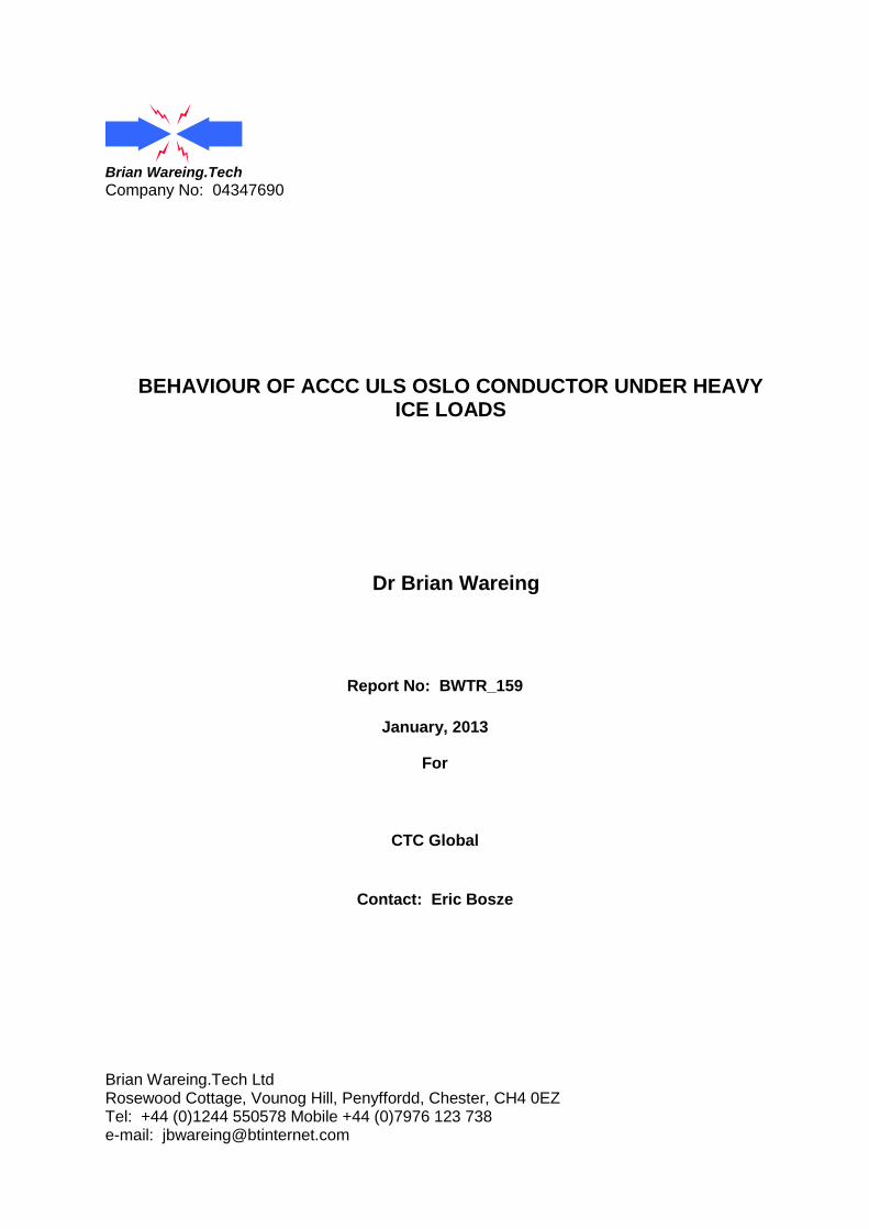
The main ice load in the 2010/11 winter occurred on 18-22 February. The load cell data is shown in Figure 5.3. The vertical lines on the Oslo tension are due to an intermittent short on the load cell. It can be seen that the ULS Oslo reached 40kN and stayed above the Lynx tension by about the same amount throughout the period. However, the Sycamore tension followed the Lynx tension until 21 February, after which its tension level did not increase at the same rate. Video data at 11:27 on 22 February shows a probable explanation for this. The conductors shown in Figure 5.4 are Lynx, ULS Oslo and Sycamore (left to right in the centre). Two other conductors under test are mounted on the far left and right. It can be seen that the Sycamore and the far right conductor are in fact resting together. From the tensions recorded it appears that the Sycamore is resting on the fifth conductor. During the incident the tension increase for the ULS Oslo was 17kN, the Sycamore (at least) 16.5kN and the Lynx 21kN. As wet snow accretes on a conductor it tends to twist it and so expose a fresh conductor surface for further accretion i.e. conductors that have low torsional rigidity can have higher ice loads. This appears to be the case here with the Lynx conductor as it has accreted a higher load than the Oslo. The Sycamore load was following the Lynx until it apparently was blown over onto an adjacent conductor.
Behaviour of ACCC ULS OSLO conductor under heavy ice loads BWTR_159
11
Conductor tensions and temperature February, 2011
-10.00
-5.00
0.00
5.00
10.00
15.00
20.00
25.00
30.00
35.00
40.00
45.00
01/02/2011 00:00 06/02/2011 00:00 11/02/2011 00:00 16/02/2011 00:00 21/02/2011 00:00 26/02/2011 00:00 03/03/2011 00:00
Ten
sio
ns (
kN
) T
em
pera
ture
(C
)
Temperature
Sycamore
Lynx
ULS Oslo
Figure 5.3 Conductor tension data for February, 2011
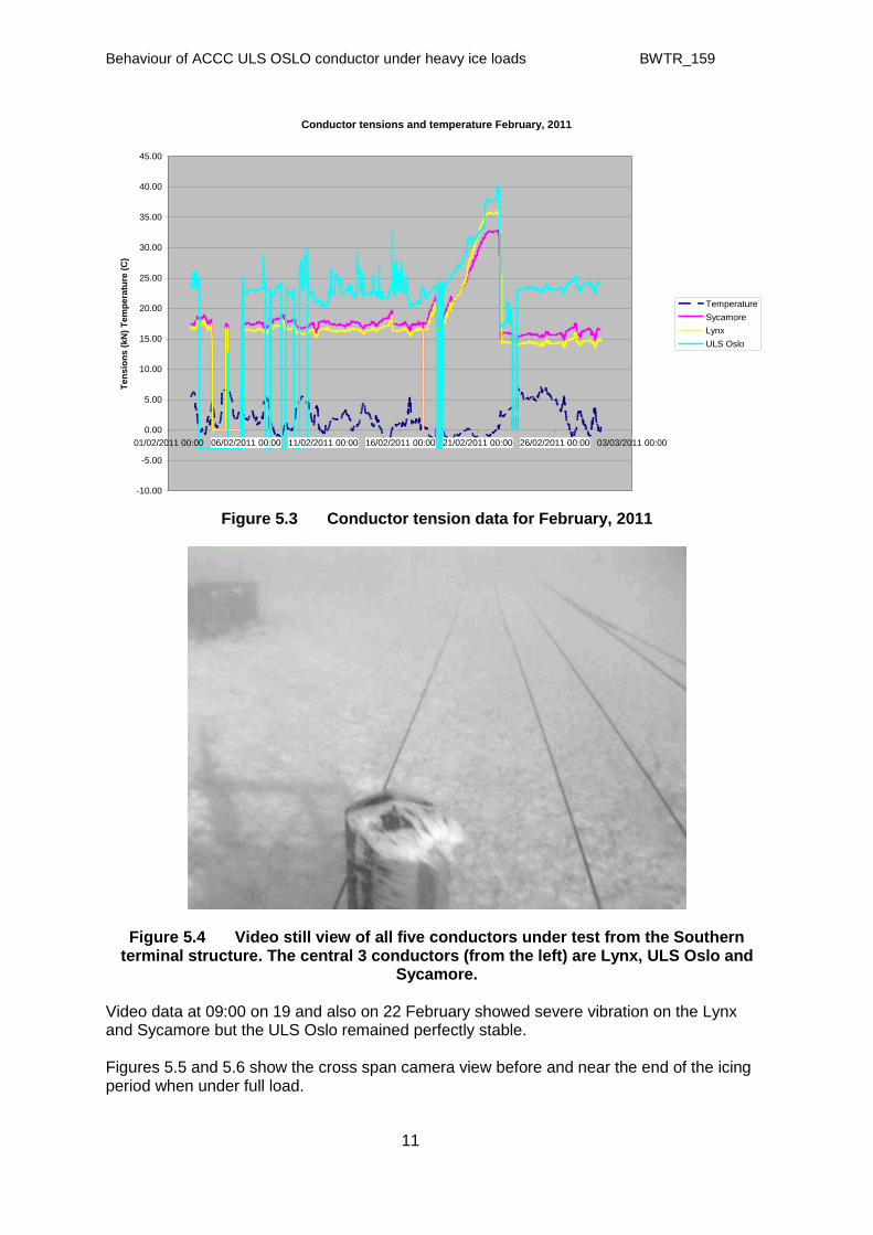
Figure 5.4 Video still view of all five conductors under test from the Southern terminal structure. The central 3 conductors (from the left) are Lynx, ULS Oslo and
Sycamore. Video data at 09:00 on 19 and also on 22 February showed severe vibration on the Lynx and Sycamore but the ULS Oslo remained perfectly stable. Figures 5.5 and 5.6 show the cross span camera view before and near the end of the icing period when under full load.

Behaviour of ACCC ULS OSLO conductor under heavy ice loads BWTR_159
12
Figure 5.5 Video still from before the icing event. The ULS Oslo (left hand marker) is seen next to the Sycamore (single central marker) with the Lynx (3 markers) just
below.
Figure 5.6 Video still at the height of the ice load with the Sycamore as the highest conductor just above the ULS Oslo and the Lynx below that.
In the one major incident mentioned, the ULS Oslo did not sag beyond the comparison conductors Sycamore and Lynx and so these initial tests indicate that the ULS Oslo will

Behaviour of ACCC ULS OSLO conductor under heavy ice loads BWTR_159
13
perform well under ice load conditions and that line design based on electrical sag will still be satisfactory when using ACCC as it is with standard AAAC and ACSR conductors. Shortly after this incident, the roof from a building next to the site blew onto the line and damaged all the conductors and the support structures, thus prematurely ending the tests. In view of the damage, the opportunity was taken to completely refurbish the site over the following 12 months.
6 SUMMARY
ACCC conductors have been tested at EA Technology’s severe weather test site at Deadwater Fell in the UK for several years. The aim was to provide a test bed for conductor behaviour in terms of vibration, erection techniques and performance under severe wind and heavy ice loads and to compare this performance against equivalent AAAC and ACSR conductors. The CTC Global ACCC conductor ‘Lisbon’ was first tested at the site six years ago. After the initial ice load and vibration tests a new version with a stronger core was produced and re-named ‘Oslo’. Recent concerns over the performance of ACCC conductors under ice load led to a further development to a ULS (ultra low sag) Oslo which had the core elastic modulus increased from 116 to147 kN/mm² and a tensile strength increased from 2.16 to to 2.59 kN/mm². The core modulus change alone was intended to reduce sags under ice load. This low sag characteristic of the ULS Oslo conductor is aimed at countries where wind and ice loads are common. As a result of past tests at Deadwater and the improved characteristics of ACCC conductors after ‘load shift’ had occurred, the ULS Oslo was erected at a tension intended to produce a fully load-shifted conductor at erection. This report shows vibration data for the Lisbon ACCC (same size as ULS Oslo) as erected without pre-tension and in a ‘load-shifted’ state. This confirmed the very low vibration levels that occur in ACCC conductors after load shifting. The ULS Oslo was erected in January, 2011, at a higher erection tension in order to put it into this load-shifted state from the start. In the worst icing incident during the 2010/11 winter, the ULS Oslo showed less sag than the comparison conductors Sycamore and Lynx and another high temperature conductor (all of equivalent size). These initial tests thus indicate that the ULS Oslo will perform well under ice load conditions.

Behaviour of ACCC ULS OSLO conductor under heavy ice loads BWTR_159
14
APPENDIX 1
ULS Oslo datasheet

Behaviour of ACCC ULS OSLO conductor under heavy ice loads BWTR_159
15
APPENDIX 2
Deadwater Fell
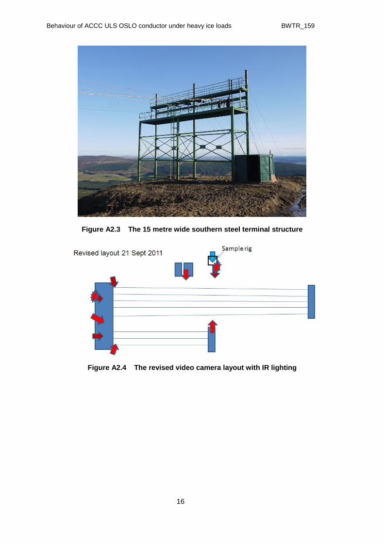
The EA Technology Deadwater Fell severe weather test site is situated at a height of 580m on an isolated, exposed hill top near the Scottish/English border (Figure A2.1), equidistant between the East and West coasts of the UK. It consists of two test spans between steel lattice structures- shown schematically in Figure A2.2. The 190m and 100m spans have independent terminal structures, each supported by 14 stay wires and with accessible platforms (Figure A2.3). It is equipped with meteorological measuring instruments and eight time lapse video cameras connected to digital video recorders (Figure A2.4). All conductors are fitted with load cells, turnbuckles and Sefag VR500-EXT vibration monitors (Figure A2.5). All data is logged at 10 minute intervals.
Fig A2.1 Deadwater Fell test site showing instrument hut
Fig A2.2 Deadwater Fell test site (schematic)
Behaviour of ACCC ULS OSLO conductor under heavy ice loads BWTR_159
16
Figure A2.3 The 15 metre wide southern steel terminal structure
Figure A2.4 The revised video camera layout with IR lighting

Behaviour of ACCC ULS OSLO conductor under heavy ice loads BWTR_159
17
Figure A2.5 The southern platform with monitors, cameras, load cells and turnbuckles
The site is unmanned but all logged data is automatically sent daily by mobile phone to EA Technology. The terminal structures are designed to withstand impulsive forces from the galloping of large conductors and also to withstand blizzard conditions. In the test spans, each conductor is fitted with a load cell and, if required, a vibration monitor. Video coverage can detect any galloping or rotation or general conductor movement under wind and ice loads. The spans are monitored 24 hours a day throughout the year by time lapse video cameras with low light level sensitivities down to 0.1 lux. The cameras are mounted within specially adapted housings with insulation, internal heating and externally wound heating tape to reduce ice growth and are used to give close-up and long distance views using environmentally friendly infra red floodlighting.
Figure A2.6 Ice envelopes from conductors at the site

Behaviour of ACCC ULS OSLO conductor under heavy ice loads BWTR_159
18
Over the last 20 years, this site has been used for conductors from 32 to 800mm² section and is now providing invaluable data but is currently looking at how new conductor types compare to 175mm² Lynx and 250mm² Sycamore conductors as these are typical 132kV conductors in the UK. The work done over the last few years is enabling conductor development to take place.