bioengineering for streambank erosion controlbbledsoe/cive413/bioengineering_for... ·...
TRANSCRIPT
Technical Report EL-97-8April 1997
US Army Corpsof EngineersWaterways Experiment
Station
Environmental Impact Research Program
Bioengineering for StreambankErosion Control
Report 1Guidelines
by Hollis H. Allen, James R. Leech
Approved For Public Release; Distribution Is Unlimited.
Prepared for Headquarters, U.S. Army Corps of Engineers

The contents of this report are not to be used for advertising,publication, or promotional purposes. Citation of trade namesdoes not constitute an official endorsement or approval of the useof such commercial products.
The findings of this report are not to be construed as anofficial Department of the Army position, unless so desig-nated by other authorized documents.
PRINTED ON RECYCLED PAPER

Environmental ImpactResearch Program
Technical Report EL-97-8April 1997
Bioengineering for StreambankErosion Control
Report 1Guidelines
by Hollis H. Allen, James R. Leech
U.S. Army Corps of EngineersWaterways Experiment Station3909 Halls Ferry RoadVicksburg, MS 39180-6199
Final report
Approved for public release; distribution is unlimited
Prepared for U.S. Army Corps of EngineersWashington, DC 20314-1000
Waterways Experiment Station Cataloging-in-Publication Data
Allen, Hollis H.Bioengineering for streambank erosion control. Report 1, Guidelines / by Hollis H. Allen,
James R. Leech ; prepared for U.S. Army Corps of Engineers.103 p. : ill. ; 28 cm. — (Technical report ; EL-97-8 rept. 1)Includes bibliographic references.1. Bioengineering. 2. Soil stabilization. 3. Soil conservation. I. Leech, James R. II.
United States. Army. Corps of Engineers. III. U.S. Army Engineer Waterways ExperimentStation) V. Environmental Impact Research Program (U.S.) VI. Title. VII. Series: Technicalreport (U.S. Army Engineer Waterways Experiment Station) ; EL-97-8 rept. 1.TA7 W34 no.EL-97-8 rept. 1
Environmental ImpactResearch Program
US Army Corpsof EngineersWaterways ExperimentStation
About the Authors: Mr. Hollis H. Allen is an ecologist, WES Environmental Laboratory. Mr. James R.Leech is a hydraulic engineer, WES Coastal and Hydraulics Laboratory.Point of contact is Mr. Allen,telephone (601) 634-3845.
Bioengineering for Streambank Erosion Control; Report 1, Guidelines(TR EL-97-8)
ISSUE: The U.S. Army Corps of Engineers is oftenrestricted from using hard structures, such as riprap orconcrete-lined channels, for streambank erosion controlbecause of environmental reasons or high cost. Bioengi-neering is the combination of biological, mechanical, andecological concepts to control erosion and stabilize soilthrough the use of vegetation or a combination of it andconstruction materials. Both living and nonliving plantscan be used. Nonliving plants are used as constructionmaterials, similar to engineered materials. Planted vege-tation controls erosion and serves as good wildlife andfisheries habitat in riparian systems. Guidelines are gen-erally lacking for use of bioengineering treatment onstreambanks, which often explains why bioengineering isnot used more often.
RESEARCH OBJECTIVE: This investigation docu-ments successful bioengineering attempts in Europe andthe United States by surveying the literature, relatingpersonal observations in Europe and the United States bythe authors, and by monitoring recently applied bioengi-neering treatments on several stream systems in variousparts of the United States. Several case studies wheretreatments were installed and monitored appear in Report 2.Examples of other treaments at various locations arerelated in Report 1. Attempts were made, where possible,to document local flow velocities and average streamvelocities to which treatments were applied. Thus, anempirical way of approximating some tolerance thresh-olds is presented that will aid designers in choosingappropriate treatments.
SUMMARY: This study provides guidelines for usingbioengineering treatments in a prudent manner while tem-
pering their widespread use with precautions. Precau-tions consist of properly designing bioengineering pro-jects with enough hardness to prevent both undercuttingthe streambank toe and erosion of the upper and lowerends (flanking) of the treated project reach. This can beaccomplished with one or both of (a) hard toe and flankingprotection, e.g., rock riprap, refusals, and (b) deflection ofwater away from the target reach to be protected throughdeflection structures, e.g., groins, hard points, and dikes.With both of these methods, appropriate plant speciesshould be used in a manner consistent with their naturalhabitats, that is, in an effort to emulate natural conditionsor processes. This is often done with streambank zonesthat more or less correspond with microhabitats of nativeplant species in local stream environments. Where possi-ble, both herbaceous and woody species are used withgrass or grass-like plants in the lowermost zone that isplanted; shrubby, woody vegetation is used in the middlezone; and, for the most part, larger shrubs and trees areestablished in the uppermost zone. These zones are re-spectively called the “splash, bank, and terrace zones.”
AVAILABILITY: The report is available on InterlibraryLoan Service from the U.S. Army Engineer WaterwaysExperiment Station (WES) Library, 3909 Halls FerryRoad, Vicksburg, MS 39180-6199; telephone (601)634-2355. To purchase a copy, call the National Techni-cal Information Service (NTIS) at (703) 487-4650. Forhelp in identifying a title for sale, call (703) 487-4780.NTIS numbers may also be requested from the WESlibrarians.
Corps of Engineers Research Report Summary, April 1997
Please reproduce this page locally, as needed.

Contents
Preface . . . . . . . . . . . . . . . . . . . . . . . . . . . . . . . . . . . . x
Conversion Factors, Non-SI to SI Units of Measurement . . . . . . . xii
1—Introduction . . . . . . . . . . . . . . . . . . . . . . . . . . . . . . . 1
Background . . . . . . . . . . . . . . . . . . . . . . . . . . . . . . . 1Purpose . . . . . . . . . . . . . . . . . . . . . . . . . . . . . . . . . 2Scope . . . . . . . . . . . . . . . . . . . . . . . . . . . . . . . . . . 2
Assets of using planted vegetation . . . . . . . . . . . . . . . 3Limitations of using planted vegetation . . . . . . . . . . . . 3
2—Bioengineering Design Model . . . . . . . . . . . . . . . . . . . . 4
Planning . . . . . . . . . . . . . . . . . . . . . . . . . . . . . . . . . 4Determine problem(s) and establish objectives . . . . . . . . 5Questions to be developed and answered . . . . . . . . . . . . 6Plan of development . . . . . . . . . . . . . . . . . . . . . . . 10Equipment and materials . . . . . . . . . . . . . . . . . . . . . 10Permit acquisition . . . . . . . . . . . . . . . . . . . . . . . . . 11Acquisition of plants . . . . . . . . . . . . . . . . . . . . . . . 11Implementation . . . . . . . . . . . . . . . . . . . . . . . . . . 11Planting techniques . . . . . . . . . . . . . . . . . . . . . . . . 12Monitoring and aftercare . . . . . . . . . . . . . . . . . . . . . 12
Hard Structures and Bioengineering . . . . . . . . . . . . . . . . . 13Bioengineering by Zones . . . . . . . . . . . . . . . . . . . . . . . 15
Toe zone . . . . . . . . . . . . . . . . . . . . . . . . . . . . . . 15Splash zone . . . . . . . . . . . . . . . . . . . . . . . . . . . . 15Bank zone . . . . . . . . . . . . . . . . . . . . . . . . . . . . . 18Terrace zone . . . . . . . . . . . . . . . . . . . . . . . . . . . . 19
Bioengineering Treatments . . . . . . . . . . . . . . . . . . . . . . 20Toe zone . . . . . . . . . . . . . . . . . . . . . . . . . . . . . . 20Splash zone . . . . . . . . . . . . . . . . . . . . . . . . . . . . 33Bank zone . . . . . . . . . . . . . . . . . . . . . . . . . . . . . 53Terrace zone . . . . . . . . . . . . . . . . . . . . . . . . . . . . 58
Velocities for Design Purposes . . . . . . . . . . . . . . . . . . . 60
3—Plant Acquisition, Handling, and Timing of Planting . . . . . . . 63
Purchasing Plants . . . . . . . . . . . . . . . . . . . . . . . . . . . 64Advantages . . . . . . . . . . . . . . . . . . . . . . . . . . . . . 65Disadvantages . . . . . . . . . . . . . . . . . . . . . . . . . . . 65
v

Collecting Plants From the Wild . . . . . . . . . . . . . . . . . . . 66Advantages . . . . . . . . . . . . . . . . . . . . . . . . . . . . . 66Disadvantages . . . . . . . . . . . . . . . . . . . . . . . . . . . 66
Growing Plants . . . . . . . . . . . . . . . . . . . . . . . . . . . . . 67Advantages . . . . . . . . . . . . . . . . . . . . . . . . . . . . . 67Disadvantages . . . . . . . . . . . . . . . . . . . . . . . . . . . 68
Handling of Plant Materials . . . . . . . . . . . . . . . . . . . . . 68Woody plants . . . . . . . . . . . . . . . . . . . . . . . . . . . 68Herbaceous plants . . . . . . . . . . . . . . . . . . . . . . . . . 69
Timing of Planting . . . . . . . . . . . . . . . . . . . . . . . . . . . 70Woody plants . . . . . . . . . . . . . . . . . . . . . . . . . . . 70Herbaceous plants . . . . . . . . . . . . . . . . . . . . . . . . . 71
4—Monitoring and Aftercare . . . . . . . . . . . . . . . . . . . . . . . 72
Philosophy of Monitoring and Aftercare . . . . . . . . . . . . . . 72Direct Documentation of Erosion Protection . . . . . . . . . . . . 73
Aerial photographic monitoring . . . . . . . . . . . . . . . . . 73Ground photographic coverage . . . . . . . . . . . . . . . . . 74Ocular description . . . . . . . . . . . . . . . . . . . . . . . . . 74
Indirect Documentation of Erosion Protection . . . . . . . . . . . 75Aftercare . . . . . . . . . . . . . . . . . . . . . . . . . . . . . . . . 75
5—Costs of Bioengineering . . . . . . . . . . . . . . . . . . . . . . . . 77
Man-Hour Costs of Bioengineering Treatments . . . . . . . . . . 79Brush mattress or matting . . . . . . . . . . . . . . . . . . . . 79Brush layering . . . . . . . . . . . . . . . . . . . . . . . . . . . 79Wattling bundles and cuttings . . . . . . . . . . . . . . . . . . 79Dormant willow post method . . . . . . . . . . . . . . . . . . 80Vegetative geogrid . . . . . . . . . . . . . . . . . . . . . . . . 81
Man-Hour Costs of Standard Vegetation EstablishmentTechniques to Supplement Bioengineering Treatments . . . . . . 81
Standard seeding . . . . . . . . . . . . . . . . . . . . . . . . . 81Hydroseeding . . . . . . . . . . . . . . . . . . . . . . . . . . . 81Hydromulching . . . . . . . . . . . . . . . . . . . . . . . . . . 81Sprigs, rootstocks or plugs, rhizomes, and tubers . . . . . . . 82Bare-root tree or shrub seedlings . . . . . . . . . . . . . . . . 82Ball and burlap trees or shrubs . . . . . . . . . . . . . . . . . 82Containerized plantings . . . . . . . . . . . . . . . . . . . . . 82
6—Summary and Recommendations . . . . . . . . . . . . . . . . . . 83
References . . . . . . . . . . . . . . . . . . . . . . . . . . . . . . . . . 85
SF 298
List of Figures
Figure 1. Steps of planning and implementing a bioengineeringproject . . . . . . . . . . . . . . . . . . . . . . . . . . . . . 5
Figure 2. River levels and flows of upper Missouri River belowGarrison Dam . . . . . . . . . . . . . . . . . . . . . . . . . 8
vi
Figure 3. Timber cribs serving as deflection structures on upperMissouri River to direct current away from bank wherethere are bioengineering treatments . . . . . . . . . . . . 14
Figure 4. Rock refusal used on an upper Missouri Riverbioengineering project . . . . . . . . . . . . . . . . . . . . 14
Figure 5. Bank zones defined on constructed slopes . . . . . . . . 16
Figure 6. Possible species to plant by zone on Missouri River . . 17
Figure 7. Schematics of bioengineering treatment usedwith a weighted rock toe with vegetation in theform of a brush mattress used above it . . . . . . . . . . 21
Figure 8. Photo of weighted rock toe revetment extendingup the bank . . . . . . . . . . . . . . . . . . . . . . . . . . 22
Figure 9. Photo of bioengineering project on upperMissouri River where large rock was used as toeprotection below large coir-covered hay bales,also forming part of toe . . . . . . . . . . . . . . . . . . . 23
Figure 10. Vegetation in the form of dormant willow posts placedlandward of rock and hay bale toe . . . . . . . . . . . . . 23
Figure 11. Rock roll used as toe protection on a bioengineeringproject, Rhine River, Germany, in city of Dusseldorf . . 24
Figure 12. System of bioengineering treatments such asgeotextile coir mats with planted vegetation on themplaced above a rock roll toe and between large rocktransverse dikes . . . . . . . . . . . . . . . . . . . . . . . 24
Figure 13. Schematic of gabions used with woody plants to forma hard structure to prevent undercutting and flanking . . 26
Figure 14. Two schematics of a LUNKERS structure designedto provide overhanging shade and protection for fishwhile serving to stabilize toe of a streambank . . . . . . 27
Figure 15. Bank crib with cover log used to protect unstablestreambanks while concurrently providing excellentoverhead cover for fish . . . . . . . . . . . . . . . . . . . 28
Figure 16. Log revetment, Roaring Fork River, Colorado . . . . . . 29
Figure 17. Schematic of log revetment with coir geotextile roll andplantings on top of backfill soil over a geotextile filter . 30
Figure 18. Installed log revetment with coir geotextile rollcombination, Roaring Fork River, Colorado . . . . . . . 31
vii
Figure 19. Schematic of root wad construction . . . . . . . . . . . . 31
Figure 20. Root wads soon after installation on Upper TruckeeRiver, California, near South Lake Tahoe . . . . . . . . . 32
Figure 21. Schematic of a coir geotextile roll and rocks . . . . . . . 34
Figure 22. Photo of coir geotextile roll and rocks with wetlandplants serving as a deflection system and providingaquatic habitat on a German stream . . . . . . . . . . . . 34
Figure 23. Coir geotextile rolls are used to stabilize streambanksand permit planting of wetland vegetation within them 35
Figure 24. Wetland plant development in a coir geotextile rollwithin the splash zone at a stream in Germany . . . . . 36
Figure 25. Coir geotextile mat being prevegetated in WESnursery in 1983 and transported to field site readyfor immediate growth . . . . . . . . . . . . . . . . . . . . 38
Figure 26. Schematics of brushmattress and wattling combination . 40
Figure 27. Sequence of brushmattress and wattling bundleinstallation . . . . . . . . . . . . . . . . . . . . . . . . . . 41
Figure 28. Schematic diagram of brush layering . . . . . . . . . . . 42
Figure 29. Installed section of brush layering . . . . . . . . . . . . . 43
Figure 30. Brush layering with willow and dogwood branchesafter one growing season; installed above a rocktoe on the Little Patuxent River, Maryland . . . . . . . . 44
Figure 31. Cross section of vegetative geogrid, also calledfabric-encapsulated soil with vegetation . . . . . . . . . 44
Figure 32. Vegetative geogrid during construction on UpperTruckee River, California, near South Lake Tahoe . . . 46
Figure 33. Vegetative geogrid in July 1995, after two growingseasons and an estimated 5-year flood during springof 1995 . . . . . . . . . . . . . . . . . . . . . . . . . . . . 46
Figure 34. Dormant willow posts, coir geotextile roll,and cedar trees being installed at Court Creek,Illinois, April 1993 . . . . . . . . . . . . . . . . . . . . . . 48
Figure 35. Court Creek site above after one growing season . . . . 48
Figure 36. Use of “The Stinger” to create pilot holes for dormantwillow posts on upper Missouri River . . . . . . . . . . 49
viii
Figure 37. Irish Creek, North Carolina, stabilized with cuttingsof bankers and streamco willow . . . . . . . . . . . . . . 52
Figure 38. Burlap and coir woven fabric laid over sedge andgrass seed, Upper Truckee River, California . . . . . . . 54
Figure 39. Wattling bundle preparation and installation . . . . . . . 55
Figure 40. Schematic illustration of live fascine bundles withcoir rope mesh fabric and long straw installed betweenbundles . . . . . . . . . . . . . . . . . . . . . . . . . . . . 57
Figure 41. Brush layering with coir woven fabric and longstraw under fabric . . . . . . . . . . . . . . . . . . . . . . 58
Figure 42. Hydroseeding and mulching operation from a barge . . 59
Figure 43. Illustrations of different expenditure profiles andmaintenance of inert structures and bioengineeringtreatments . . . . . . . . . . . . . . . . . . . . . . . . . . . 72
Figure 44. Aerial monitoring of bioengineering treatment . . . . . . 74
ix
Preface
The work described herein was authorized by Headquarters, U.S. ArmyCorps of Engineers (HQUSACE), as part of the Environmental Impact Re-search Program (EIRP). The work was performed under Work Unit32830, Bioengineering for Streambank Erosion Control. Messrs. Hollis H.Allen and James R. Leech, Environmental (EL) and Coastal and Hydraulics(CHL) Laboratories, respectively, of the U.S. Army Engineer WaterwaysExperiment Station (WES), were the Principal Investigators of this workunit. Ms. Cheryl Smith and Messrs. Frederick B. Juhle and ForresterEinersen were the HQUSACE Program Monitors for this work.
Mr. Dave Mathis wes the EIRP Coordinator at the Directorate of Re-search and Development, HQUSACE. Dr. Russell F. Theriot, WES, wasthe EIRP Program Manager.
Participants in the study, in addition to the authors, included severalscientists and practitioners from State agencies and private consultants.These included Ms. Wendi Goldsmith, Bioengineering Group, Salem,MA; Messrs. Donald Roseboom, Thomas Hill, and Jon Rodsater, IllinoisState Water Survey, Peoria, IL; Mr. Alan Czenkusch, Colorado Divisionof Wildlife, Aspen, CO; Messrs. William N. Johnson and Sky DeBoer,Earth Resource Investigations, Carbondale, CO; and Mses. Catherine D.MacDonald and Cynthia M. Walck, California Department of Parks andRecreation.
Special thanks is extended to Messrs. Bill Miller and David LaGrone,U.S. Army Engineer District, Omaha, for contributing to documentationof a bioengineering project on the upper Missouri River, near Wolf Point,Montana. Mr. Miller was project manager for the stabilization project andMr. LaGrone was design engineer.
Thanks is extended to several persons who helped review the manuscript.These include Dr. Craig Fischenich, EL, and Messrs. Chester Martin, EL,and Noel R. Oswalt, Hydraulic Engineer, retired from CHL. Permissionto use copyrighted material was obtained from Land and Water, Inc., FortDodge, IA (Figures 19, 30, and 31), and the Construction Industry Re-search and Information Association, London (Figures 13 and 43).
The report was written by Messrs. Allen and Leech under the directsupervision of Dr. Michael F. Passmore, Chief, Stewardship Branch, EL,and under the general supervision of Dr. Robert M. Engler, Chief, Natural
x

Resources Division, EL, and Dr. John W. Keeley, Assistant Director, EL,and Dr. John Harrison, Director, EL.
At the time of publication of this report, Director of WES wasDr. Robert W. Whalin. Commander was COL Bruce K. Howard, EN.
This report should be cited as follows:
Allen, H. H., and Leech, J. R. (1997). “Bioengineering forstreambank erosion control; Report 1, Guidelines,” TechnicalReport EL-97-8, U.S. Army Engineer Waterways ExperimentStation, Vicksburg, MS.
The contents of this report are not to be used for advertising, publication,or promotional purposes. Citation of trade names does not constitute anofficial endorsement or approval of the use of such commercial products.
xi

Conversion Factors, Non-SI to SIUnits of Measurement
Non-SI units of measurement used in this report can be converted to SIunits as follows:
Multiply By To Obtain
cubic feet 0.02831685 cubic meters
degrees (angle) 0.01745329 radians
Fahrenheit degrees 5/9 Celsius degrees or kelvins1
feet 0.3048 meters
inches 2.54 centimeters
pounds (mass) 0.4535924 kilograms
quarts (U.S. liquid) 0.9463529 liters
tons (2,000 pounds, mass) 907.1847 kilograms
1 To obtain Celsius (C) temperature readings from Fahrenheit (F) readings, use thefollowing formula: C = (5/9) (F-32). To obtain kelvin (K) readings, use the following formula:K = (5/9) (F-32) + 273.15.
xii

1 Introduction
Background
The U.S. Army Corps of Engineers (CE) and others are often restrictedfrom using hard structures, such as riprap or concrete-lined channels, forstreambank erosion control partly because of environmental reasons andhigh cost. Within the last decade or so, increased demands have beenplaced upon the CE by environmental agencies and others to incorporatevegetation into their streambank erosion control projects rather than torely completely on traditional methods. Complete bank armorment by vari-ous methods such as riprapped revetment, concrete revetment, bulkheads,concrete linings, etc., are considered by many to have little value for fish-eries, wildlife, water quality, and aesthetic appeal. Bioengineering, in con-trast, is receiving more emphasis from environmental agencies andconservation organizations. Bioengineering is the combination of biologi-cal, mechanical, and ecological concepts to control erosion and stabilizesoil through the sole use of vegetation or in combination with constructionmaterials. Both living and nonliving plants can be used. Nonliving plantsare used as construction materials, similar to engineered materials. Theplanted vegetation controls erosion and serves as good wildlife and fisher-ies habitat in riparian systems.
A limited number of streambank erosion control projects have been de-signed and implemented by the CE where bioengineering has been pur-posely planned as a part of the project. The CE has historically relied onconstruction projects with design lives of 50 to 100 years that require aminimum amount of maintenance. Therefore, the focus of developmenthas been on hard structures that can be modeled and studied in hydraulicflumes and other test structures and are designed to stay in place a longtime. The CE has been reluctant to design softer treatments, e.g., bioengi-neering, for erosion control because of a lack of specific design guidance.For instance, under what velocity conditions will certain vegetative treat-ments work? This type of information has been slow to develop. In part, alack of monitoring after streambanks have been treated with a vegetativemethod has led to unknown performance conditions and failure thresholds.In 1993, efforts were taken under the purview of the Environmental Im-pact Research Program (EIRP), sponsored by Headquarters, U.S. ArmyCorps of Engineers, to develop and demonstrate bioengineering conceptsfor streambank erosion control and to determine hydraulic velocities andconditions for successful prototype performance and use.
Chapter 1 Introduction1
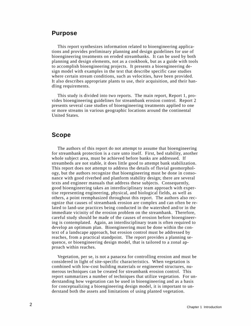
Purpose
This report synthesizes information related to bioengineering applica-tions and provides preliminary planning and design guidelines for use ofbioengineering treatments on eroded streambanks. It can be used by bothplanning and design elements, not as a cookbook, but as a guide with toolsto accomplish bioengineering projects. It presents a bioengineering de-sign model with examples in the text that describe specific case studieswhere certain stream conditions, such as velocities, have been provided.It also describes appropriate plants to use, their acquisition, and their han-dling requirements.
This study is divided into two reports. The main report, Report 1, pro-vides bioengineering guidelines for streambank erosion control. Report 2presents several case studies of bioengineering treatments applied to oneor more streams in various geographic locations around the continentalUnited States.
Scope
The authors of this report do not attempt to assume that bioengineeringfor streambank protection is a cure unto itself. First, bed stability, anotherwhole subject area, must be achieved before banks are addressed. Ifstreambeds are not stable, it does little good to attempt bank stabilization.This report does not attempt to address the details of fluvial geomorphol-ogy, but the authors recognize that bioengineering must be done in conso-nance with good riverbed and planform stability design; there are severaltexts and engineer manuals that address these subjects. Consequently,good bioengineering takes an interdisciplinary team approach with exper-tise representing engineering, physical, and biological fields, as well asothers, a point reemphasized throughout this report. The authors also rec-ognize that causes of streambank erosion are complex and can often be re-lated to land-use practices being conducted in the watershed and/or in theimmediate vicinity of the erosion problem on the streambank. Therefore,careful study should be made of the causes of erosion before bioengineer-ing is contemplated. Again, an interdisciplinary team is often required todevelop an optimum plan. Bioengineering must be done within the con-text of a landscape approach, but erosion control must be addressed byreaches, from a practical standpoint. The report provides a planning se-quence, or bioengineering design model, that is tailored to a zonal ap-proach within reaches.
Vegetation, per se, is not a panacea for controlling erosion and must beconsidered in light of site-specific characteristics. When vegetation iscombined with low-cost building materials or engineered structures, nu-merous techniques can be created for streambank erosion control. Thisreport summarizes a number of techniques that utilize vegetation. For un-derstanding how vegetation can be used in bioengineering and as a basisfor conceptualizing a bioengineering design model, it is important to un-derstand both the assets and limitations of using planted vegetation.
2Chapter 1 Introduction
Assets of using planted vegetation
Gray (1977), Bailey and Copeland (1961), and Allen (1978) discussfive mechanisms through which vegetation can aid erosion control: rein-force soil through roots (Gray 1977); dampen waves or dissipate wave en-ergy; intercept water; enhance water infiltration; and deplete soil waterby uptake and transpiration. Klingeman and Bradley (1976) point out fourspecific ways vegetation can protect streambanks. First, the root systemhelps hold the soil together and increases the overall bank stability by itsbinding network structure, i.e., the ability of roots to hold soil particlestogether. Second, the exposed vegetation (stalks, stems, branches, andfoliage) can increase the resistance to flow and reduce the local flow ve-locities, causing the flow to dissipate energy against the deforming plantrather than the soil. Third, the vegetation acts as a buffer against the abra-sive effect of transported materials. Fourth, close-growing vegetation caninduce sediment deposition by causing zones of slow velocity and lowshear stress near the bank, allowing coarse sediments to deposit. Vegeta-tion is also often less expensive than most structural methods; it improvesthe conditions for fisheries and wildlife, improves water quality, and canprotect cultural/archeological resources.
Limitations of using planted vegetation
Using planted vegetation for streambank erosion control also has limita-tions. These may include its occasional failure to grow; it is subject to un-dermining; it may be uprooted by wind, water, and the freezing andthawing of ice; wildlife or livestock may feed upon and depredate it; andit may require some maintenance. Most of these limitations, such as un-dermining, uprooting by freezing and thawing, etc., can often be lessenedor prevented by use of bioengineering measures.
Chapter 1 Introduction3
2 Bioengineering DesignModel
A conceptual design model is offered below that leads one through thesteps of planning and implementing a bioengineering project. It drawslargely upon similar thought processes presented by Leiser (1992) for useof vegetation and engineered structures for slope protection and erosioncontrol. Where appropriate, the report will reference examples in themain text (Report 1) and case studies (Report 2) that describe particularbioengineering treatments on selected and monitored stream systems. Themodel includes planning and its associated components that will be de-fined below; use of hard structures and bioengineering; a vegetative zonalconcept; and various bioengineering fixes by zone. Monitoring, follow-up,and care should naturally follow.
Planning
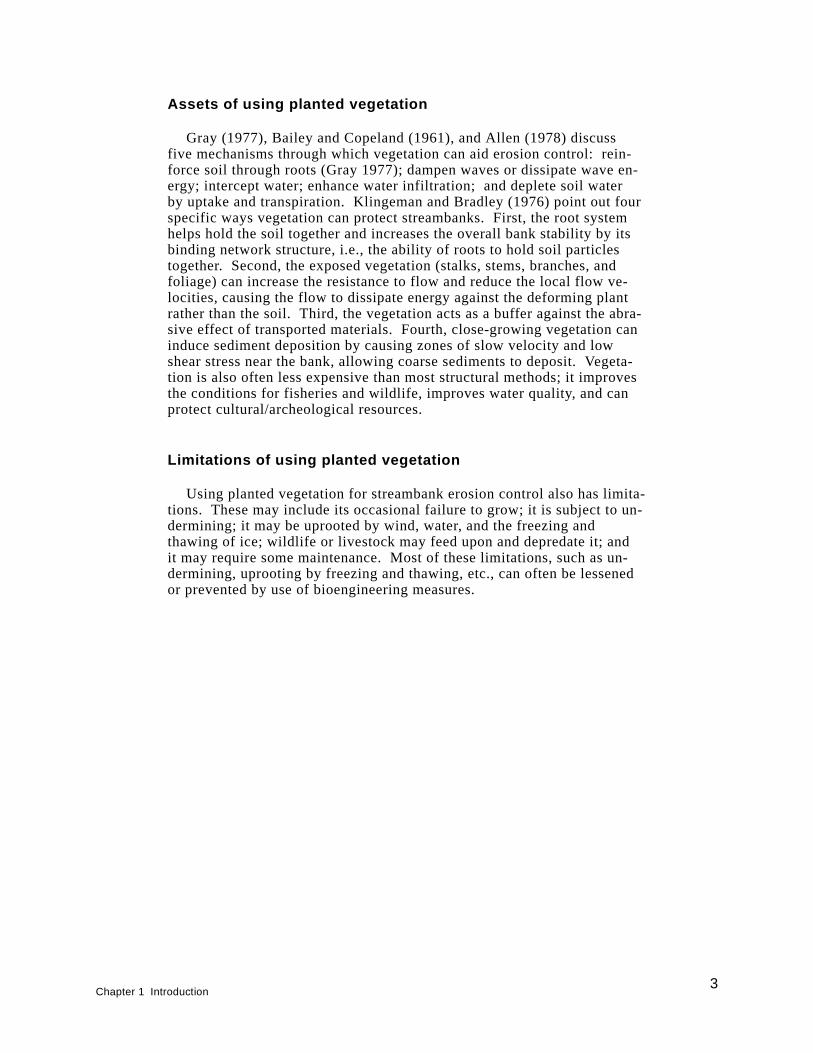
A bioengineering project may be primarily desired for erosion control, butoften there are other considerations. Thought should be given to importantfunctions that the bioengineering treatment can perform, such as habitat de-velopment, archeological site protection, water quality improvement, aesthet-ics, or a combination of these. The political and economical requirements orconstraints of implementing any project must be considered. Any bioengi-neering streambank stabilization project should be planned within the contextof the landscape in which the stream is located. Additionally, the bioengi-neering work cannot be accomplished without determining the upstream,downstream, and cross-stream impacts. Any action on a stream results in areaction. The bioengineering project may direct flows toward the adjacentproperty owner or includes fill that raises the water surface on opposite bankproperty. These considerations must be taken into account. Activities nearthe stream that is influencing its erosion must be identified. It is a wastedeffort to install bioengineering treatments in an area where cattle are allowedaccess to the treated reach immediately after construction. The stream mustbe examined as a system, but the restoration must be accomplished at thereach level from a practical perspective. The planning part of the modelshould address potential functions of the treatment and the political andeconomical concerns (Figure 1).
4Chapter 2 Bioengineering Design Model
Determine problem(s) and establish objectives
Clear-cut objectives that are based on some perceived problem or prob-lems are needed for any project. The problem or problems may be resultsof erosion, such as poor water quality, lack of fisheries, lack of suitablewater for kayaks, and others. The objectives are then driven by these andmay relate to primarily erosion control, but may also include providingfisheries or wildlife habitat, improving water quality, protection of cul-tural resources, or a host of other desired functions. Bowers (1992) estab-lished objectives on the Little Patuxent River, Maryland, that included notonly erosion control, but also in-stream and riparian habitat enhancement.These objectives are often driven not only by the physical impacts of ero-sion on the landscape, but by legal mandates, such as mitigation for someaction on the stream. Questions must be asked and answers provided be-fore the project can proceed. This effort will require that an interdiscipli-nary team be developed consisting minimally of engineers, hydrologists,and life scientists with expertise in bioengineering approaches. Other dis-ciplines, such as economists, sociologists, and attorneys can be consultedas needed during the planning stage of development.
Figure 1. Steps of planning and implementing a bioengineering project
Chapter 2 Bioengineering Design Model5
Questions to be developed and answered
Any streambank erosion control project has several components. Eachcomponent may have constraints that have to be overcome. These compo-nents with associated constraints are interdependent and must be consid-ered, thus generating an abundance of questions that should be answered,if possible. They include the political, economic, climatological, physi-cal, edaphic (soils), and biological components of the project. Both theasking and answering of these questions relative to these components leadto the Plan of Development. Once the plan is developed and permits ac-quired, procurement of plants will be required (See Chapter 3). After orconcurrent with this procurement, implementation of the plan can proceed.The political component includes governmental regulations, such as thosepresented in Section 404 of the the Clean Water Act (formerly known asthe Federal Water Pollution Control Act, 33 U.S.C. 1344). It also includespublic pressures, such as restricting bioengineering to the use of only na-tive plant species or plants that are grown in a nursery as opposed to thoseharvested from the wild. Governmental regulations and/or public pres-sures may also mandate that certain vegetation species or types of speciesbe used. If a certain species blocks the view of a river in an urban setting,for instance, public pressures may cause plans to change to use a differentspecies or a different erosion control treatment altogether. Lack of graz-ing controls, limitations on use of chemicals for rodent, insect, or weedcontrol or fertilizers are other examples of these constraints and must beconsidered in any bioengineering design criteria protocol. The politicalcomponent also includes the negative human factors of vandalism and tres-pass by foot and off-road vehicles, as well as the positive factor of publicpressure for improvement of the environment.
The economic component could be one of the more important factors toenable bioengineering erosion control efforts. Usually, bioengineeringprojects are less expensive than traditional engineering approaches. How-ever, economics invariably affects the final decisions on the selection ofplant species and planting densities, as well as preproject experimentationand aftercare activities. A bioengineering design protocol must includefunding for monitoring and allow for remedial planting and managementof the site to meet the objectives of the project. Bioengineering projectswill often require more funds early in the project’s history for possible re-pair and assurrance of effectiveness than traditional engineering, but willbe more self-sustaining and resilient over the long term. If traditional en-gineering projects need remediation over the life of the project (and theyfrequently do), the remediation occurs later in the life of the project butwith higher overall costs.
The climatological component includes several aspects of a projectsite: rainfall (amount and distribution), temperature (heat and cold, time,duration, and intensity), humidity, day length, etc. Climatological compo-nents affect plant species selection, how those plants will be planted, andtreatment after planting. With some exceptions, bioengineering projectsin humid regions with ample rainfall and projects along permanent flowingstreams will probably require less effort to establish vegetation than thosealong intermittent flowing streams in dry climates. In desert climates,where fewer plants in the inventory can be chosen than in humid climates,learning these plants’ life requisites is essential for successful planting.
6Chapter 2 Bioengineering Design Model

The probability for bioengineering project failure is higher with fewer spe-cies planted and where growth stresses are greater.
The physical component includes physical parameters of a project: sitestability such as subsidence or accretion; aspect (direction slope faces),which in turn influences environmental factors such as temperature (south-and southwest-facing sites are hotter, and evapotranspiration is higherthan in other directions); hydrodynamic aspects such as water sources(groundwater, surface water) and water frequency, timing, depth, duration,and flooding relationship to bank height; fluvial geomorphology such ashistorical stream meander, pattern, cross-sectional, and longitudinal pro-files and energy sources such as wave and current action; and geomorphicfeatures such as landforms and terrain influences, e.g., impacts of offsitewater sources.
From the above list of physical parameters, hydrologic and geomorphicfactors are particularly important. For purposes of determining where touse vegetation on the bank and the kinds of vegetation to use and when toplant, one needs a knowledge of the stream’s hydrographic and fluvial geo-morphic characteristics. If stream gauge data are not available, one willhave to rely on high water marks, the knowledge of persons living in theareas, and any other data derived from local vegetation and soils that indi-cate flood periodicity. Table 1 gives an example of hydrologic charac-teristics of the upper Missouri River. It shows the frequency of variousflows and their duration with 25,000 cfs1 being the normal flow from latespring through fall. A 40,000-cfs flow with a duration of 6 months can beexpected to occur once every 10 years. Figure 2 subsequently shows theapproximate water level corresponding to various river flows using thelevel of 25,000 cfs as the reference. At a flow of 40,000 cfs, the river
Table 1Recurrence Interval by Discharge and Duration on UpperMissouri River 1
Discharge, cfs
Duration % Probabilityof NotOccurring (60Days)6 Months 60 Days 1 Day
60,000 — 1/100 years 1/20 years 99
50,000 1/100 1/10 1/5 90
40,000 1/10 1/3 1/2 67
35,000 1/3 1/2 1 50
30,000 1/2 1 1 1
25,000 1 — — —
Chapter 2 Bioengineering Design Model7
1A table of factors for converting non-SI units of measurement to SI units is presented
on page xii.
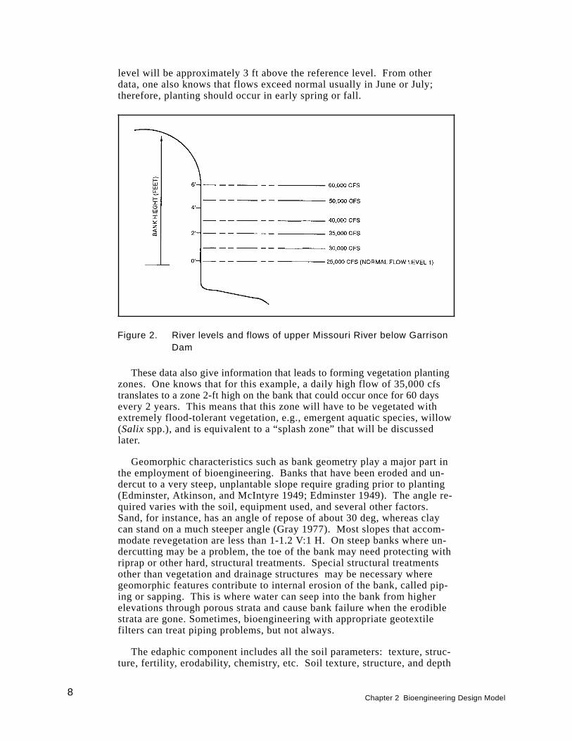
level will be approximately 3 ft above the reference level. From otherdata, one also knows that flows exceed normal usually in June or July;therefore, planting should occur in early spring or fall.
These data also give information that leads to forming vegetation plantingzones. One knows that for this example, a daily high flow of 35,000 cfstranslates to a zone 2-ft high on the bank that could occur once for 60 daysevery 2 years. This means that this zone will have to be vegetated withextremely flood-tolerant vegetation, e.g., emergent aquatic species, willow(Salix spp.), and is equivalent to a “splash zone” that will be discussedlater.
Geomorphic characteristics such as bank geometry play a major part inthe employment of bioengineering. Banks that have been eroded and un-dercut to a very steep, unplantable slope require grading prior to planting(Edminster, Atkinson, and McIntyre 1949; Edminster 1949). The angle re-quired varies with the soil, equipment used, and several other factors.Sand, for instance, has an angle of repose of about 30 deg, whereas claycan stand on a much steeper angle (Gray 1977). Most slopes that accom-modate revegetation are less than 1-1.2 V:1 H. On steep banks where un-dercutting may be a problem, the toe of the bank may need protecting withriprap or other hard, structural treatments. Special structural treatmentsother than vegetation and drainage structures may be necessary wheregeomorphic features contribute to internal erosion of the bank, called pip-ing or sapping. This is where water can seep into the bank from higherelevations through porous strata and cause bank failure when the erodiblestrata are gone. Sometimes, bioengineering with appropriate geotextilefilters can treat piping problems, but not always.
The edaphic component includes all the soil parameters: texture, struc-ture, fertility, erodability, chemistry, etc. Soil texture, structure, and depth
Figure 2. River levels and flows of upper Missouri River below GarrisonDam
8Chapter 2 Bioengineering Design Model

all affect the water holding capacity of a soil and need to be consideredwhen determining water retention requirements or supplemental irrigationrequirements during dry periods of the year. In addition to ensuringproper bank slopes and bank toe protection, attention should be given tothe edaphic component that may in turn require some site preparation ac-tivities. It is desirable to have slopes covered with at least a 10-cm layerof topsoil high in organic matter; this can be stockpiled prior to any grad-ing. Movement of soil, however, is expensive and must be considered inlight of the economic practicality. In lieu of moving rich topsoil, the exist-ing substrate may be amended with fertilizer and mulch to help produce abetter soil. In any case, plants need a growing medium that supports theplant and facilitates nutrient and water uptake. The site may require othersoil amendments such as lime, gypsum, or other special nutrients depend-ing upon the soil’s pH and fertility. Soil tests should be conducted priorto revegetation to determine any amendments needed.
The biological component is one of the most important components andis interdependent with the other components. It includes habitat require-ments of animal and plant species and the plan can be modified to someextent to meet these requirements if the life requisites of these species areknown. This component also includes the availability of suitable plantspecies that, in part, make up the habitat for various riparian animals.Choices must be made between native and introduced species, plants ob-tained from commercial nurseries, or from the wild. This component alsoincludes the propagation and cultural practice for the plants, planting, andaftercare. It includes plant diseases, insects, predators, and the presenceor absence of grazing animals. An example of spider mite damage is pre-sented in the case study of Court Creek, Illinois, Report 2, where willowhad to be sprayed with an insecticide to control damage. If spraying hadnot occurred, streambank protection with living willow would not havebeen achieved. Protective screen sleeves or deer and grazing animal exclo-sures must be provided if these risks are present. The potential for dam-age from insect, rodent, deer, and other predation must be considered andprotection provided to planted wetland vegetation.
The biological attributes of an area containing a bioengineering site arevery important and plants are no exception. They are there because theyhave adapted to the ecological conditions of the area, such as climate,soils, etc. To use bioengineering effectively, one should learn to identifyand evaluate plants that are growing in the area that have become adapted.These should include plants that are growing along all parts of the stream-bank, lower, middle, and upper. In bioengineering, these conditions andspecies should be emulated as much as possible. Native plants or plantsthat have become naturalized in the area should normally be used. Exoticplants should be avoided since there are species that may get out of con-trol and become nuisances. One only has to look at examples such as pur-ple loosestrife (Lythrum salicaria) to gain an appreciation of theproblems exotic plants can cause.
Plants chosen should have some tolerance to flooding. Some will needto be highly tolerant (those planted lower on the bank) while others (thoseplanted higher on the bank) can be less tolerant. Plants chosen also willhave to withstand some dry conditions as well as flooded conditions be-cause of the fluctuating nature of water levels in streams.
Chapter 2 Bioengineering Design Model9
A mixture of grasses, herbs, shrubs, and trees should be used, if possi-ble, to provide a diversity of wildlife habitats. Some legumes such as yel-low sweet clover (Melilotus officinalis), white sweet clover (M. alba), andcrownvetch (Coronilla varia) are possible choices because of their nitro-gen-fixing attributes. These, however, should be used at an elevation sub-ject to only intermittent and short periods of flooding, such as in the upperbank and terrace zones discussed below.
Plan of development
The plan of development is the culmination of answering all the ques-tions in the various categories mentioned above. Many of the questions re-garding the above components can be answered offsite, but a site analysisis mandatory before plants can be procured or before project implementa-tion can occur. In the site analysis, each component must again be exam-ined to include the various factors or parameters and what will influencevegetation development for bioengineering and the stability of a stream-bank. A general guideline for the site analysis is to be a keen observer asto the conditions occurring at the project reach as well as upstream anddownstream from it. From observations of a reference site, many answerscan be found about what kinds of plants to use, invader species that areapt to occur, causes of problems, such as overgrazing, road constructionupstream contributing to a high bed load of sediment, etc. The same orsimilar plant species that occur at the reference site should be acquired.In a site analysis, much of the data from a reference streambank area canbe taken to answer the questions posed.
Equipment and materials
In the plan of development, consideration should be given to the equip-ment and materials required for vegetation handling and planting at the im-plementation stage. The tools required and the planting techniques willdepend on the type of vegetation, i.e., woody or herbaceous, the size ofplants, soils, and the size of the project and site conditions. Freshwaterherbaceous plantings with low-wave or current-energy environments maycall for tools like spades, shovels, and buckets. In contrast, high-energyenvironments of waves and currents may require tools for bioengineeringinstallations. Such tools include chain saws, lopping and hand pruners forthe preparation of woody cuttings, and materials for woody bioengineeringmethods; or heavy hammers and sledges for driving stakes in bioengineer-ing treatments such as wattling and brush matting. Specialized equipmentmay be required. This is true when moving sod or mulches containingwetland plants or plant propagules. It is also true since bioengineeringprojects often have the constraints of working in a pristine stream systemwhere riparian corridors are extremely valuable, particularly in large, urbansettings. It is in these settings that equipment size and type constraints areoften placed upon the project. Thus, downsized front-end loaders andwalking excavators are sometimes required to minimize disturbance ofexisting vegetation and soil. Other equipment and materials may includefertilizers, soil amendments, (e.g., lime), fencing for plant protection, andirrigation equipment for keeping plants alive during dry conditions. Other
10Chapter 2 Bioengineering Design Model
equipment and materials for keeping plants alive before they are plantedmay include shading materials such as tarps, buckets with water for hold-ing plants, and water pumps and hoses for watering or water trucks.
Permit acquisition
After the site analysis and bioengineering actions are determined, nec-essary permits must be obtained, such as those governing any action im-pacting wetlands, water quality, cultural/historical resources, threatenedand endangered species, and navigation. Usually and especially onsmaller streams not requiring large structures or bank shaping as a part ofthe design, the permit process will not be very complex or time-consuming.However, on large streams where deflection structures are employed orwhere banks are extensively shaped, navigation, cultural resource, andwetland permits can take several months to acquire. Depending on thesize and complexity of the project, National Environmental Protection Actcompliance documents may also be required.
Acquisition of plants
Prior to the implementation of the project, the plans for acquiringplants must be made well in advance (sometimes 1-2 years). To selectvegetation for the project, vegetation existing on or near a site and on simi-lar nearby areas which have revegetated naturally are the best indicatorsof the plant species to use. If commercial plant sources are not available(U.S. Department of Agriculture (USDA) Soil Conservation Service 1992),then onsite or offsite harvesting can be considered. When acquiring plants,care must be given to local or Federal laws prohibiting such plant acquisi-tion and decimating the natural stands of wetland plants. Additionally,care must be taken to ensure that pest species, such as purple loosestrife,are not collected and transferred to the project site.
The availability of plants of the appropriate species, size, and quality isoften a limiting factor in the final selection and plant acquisition process.Some native plant species are very difficult to propagate and grow, andmany desirable species are not commonly available in commerce or notavailable as good quality plants. As demand increases and nurserymengain more experience in growing native plant species, this limitationshould become less important (Leiser 1992). Plant species compositionand quantity can often be determined from the project objectives and func-tions desired. As a general rule, it is advisable to specify as many speciesas possible and require the use of some minimum number of these species.Maximum and minimum numbers of any one species may be specified.See Chapter 3 for additional information on plant acquisition, times ofplanting, and plant-handling techniques.
Implementation
Implementation is the natural follow-up to the plan of development andis integrated with the planning process. It should not be separated from it.
Chapter 2 Bioengineering Design Model11
It is the final stage of the conceptual and detailed design but may requirefeedback into design plan formulation for possible onsite corrections. It in-cludes site preparation and construction, planting, monitoring, and after-care. For the bioengineering design to be successful, it must have closesupervision throughout by someone familiar with implementation of bioen-gineering projects. This stage requires close attention to detail. It is im-portant in this stage to maintain continuity of the same interdisciplinaryteam who planned and designed the project and keep them involved in thispart of the project. Those capable of actually carrying out the projectshould be a team of persons with knowledge and experience of bothstream morphology and mechanics, hydraulic and geotechnical engineering,and bioengineering. Regarding vegetation, the person should possess bothtraining and experience in wetlands plant science and development. It ismandatory that the person be onsite intermittently at least during projectconstruction and especially planting. All of the efforts to address the vari-ous components of design will be in vain unless plants are handled andcared for properly when planted and even after planting in many cases.
Planting techniques
There are several planting techniques for bioengineering ranging fromsimple digging with shovels or spades and inserting sprigs (rooted stems)or cuttings to moving large pieces of rooted material, such as sod, mulch,and root pads (large rooted shrubs). Other methods consist of direct seed-ing, hydroseeding, or drilling individual seeds such as acorns of wetlandoak species. All of the above methods capitalize on combining the attib-utes of plants with some kind of engineered material or structure or rely-ing on the plant itself to form a resistant structure to erosion, such as alive willow post revetment. Various techniques will be discussed in detailbelow.
Monitoring and aftercare
Most importantly, monitoring and necessary aftercare must be a part ofany bioengineering design and must be included in the plan of develop-ment and the implementation stage. The intensity and frequency of moni-toring and aftercare will depend on site conditions, such as harshness ofclimate, probability of animal disturbance, high-wave or current condi-tions, etc., and on established success criteria.
On many sites, it is essential to protect plantings from damage by ani-mals, such as Canada geese (Branta canadensis) or beaver (Casta ca-nadensis) and other mammals. The use of irrigation may be requiredduring aftercare and will improve growth and survival of plantings thatare installed during dry seasons and in dry soils. The decision about irri-gation must be made based on economics contrasting the need to irrigatewith the cost of possible mortality and the consequences of failing to ob-tain the desired erosion control and other functions. See Chapter 4 formore detail on monitoring.
12Chapter 2 Bioengineering Design Model
Hard Structures and Bioengineering
Generally speaking, bioengineering is considered “a soft fix.” This isnot necessarily the case. On first or second order streams, the sole use ofvegetation with perhaps a little wire and a few stakes for holding the vege-tation until it is established makes bioengineering more of a soft treat-ment. However, bioengineering is used also in combination with hardstructures. These hard structures are used to protect the toe of the bankfrom undercutting and the flanks (ends of treatment) from eroding. Thelarger the stream or stronger the flow, the more probable that hard struc-tures will be incorporated into the bioengineering design model. This isalso true when risks become greater, such as when an expensive facility isbeing threatened. As an example, a utility tower along a stream in Georgia1
was being threatened by erosion. A rock revetment had previously beenused in front of the tower, but was washed out. A bioengineering treat-ment that incorporated live willow whips and a log crib were installed tocontrol erosion. Crib logs controlled undercutting and flanking while thelive willow whips installed between the log stringers developed andstrengthened the overall structure and gave it a “green” appearance.
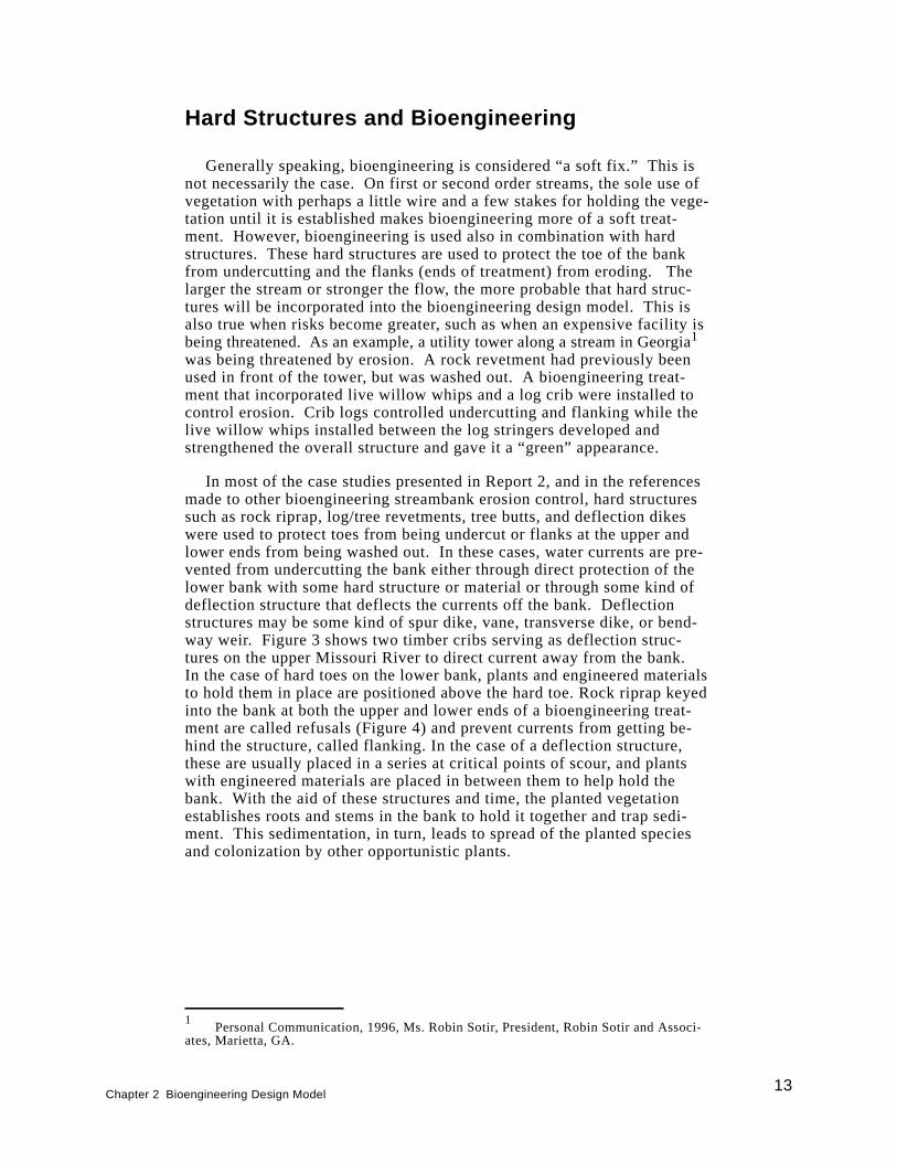
In most of the case studies presented in Report 2, and in the referencesmade to other bioengineering streambank erosion control, hard structuressuch as rock riprap, log/tree revetments, tree butts, and deflection dikeswere used to protect toes from being undercut or flanks at the upper andlower ends from being washed out. In these cases, water currents are pre-vented from undercutting the bank either through direct protection of thelower bank with some hard structure or material or through some kind ofdeflection structure that deflects the currents off the bank. Deflectionstructures may be some kind of spur dike, vane, transverse dike, or bend-way weir. Figure 3 shows two timber cribs serving as deflection struc-tures on the upper Missouri River to direct current away from the bank.In the case of hard toes on the lower bank, plants and engineered materialsto hold them in place are positioned above the hard toe. Rock riprap keyedinto the bank at both the upper and lower ends of a bioengineering treat-ment are called refusals (Figure 4) and prevent currents from getting be-hind the structure, called flanking. In the case of a deflection structure,these are usually placed in a series at critical points of scour, and plantswith engineered materials are placed in between them to help hold thebank. With the aid of these structures and time, the planted vegetationestablishes roots and stems in the bank to hold it together and trap sedi-ment. This sedimentation, in turn, leads to spread of the planted speciesand colonization by other opportunistic plants.
Chapter 2 Bioengineering Design Model13
1Personal Communication, 1996, Ms. Robin Sotir, President, Robin Sotir and Associ-
ates, Marietta, GA.
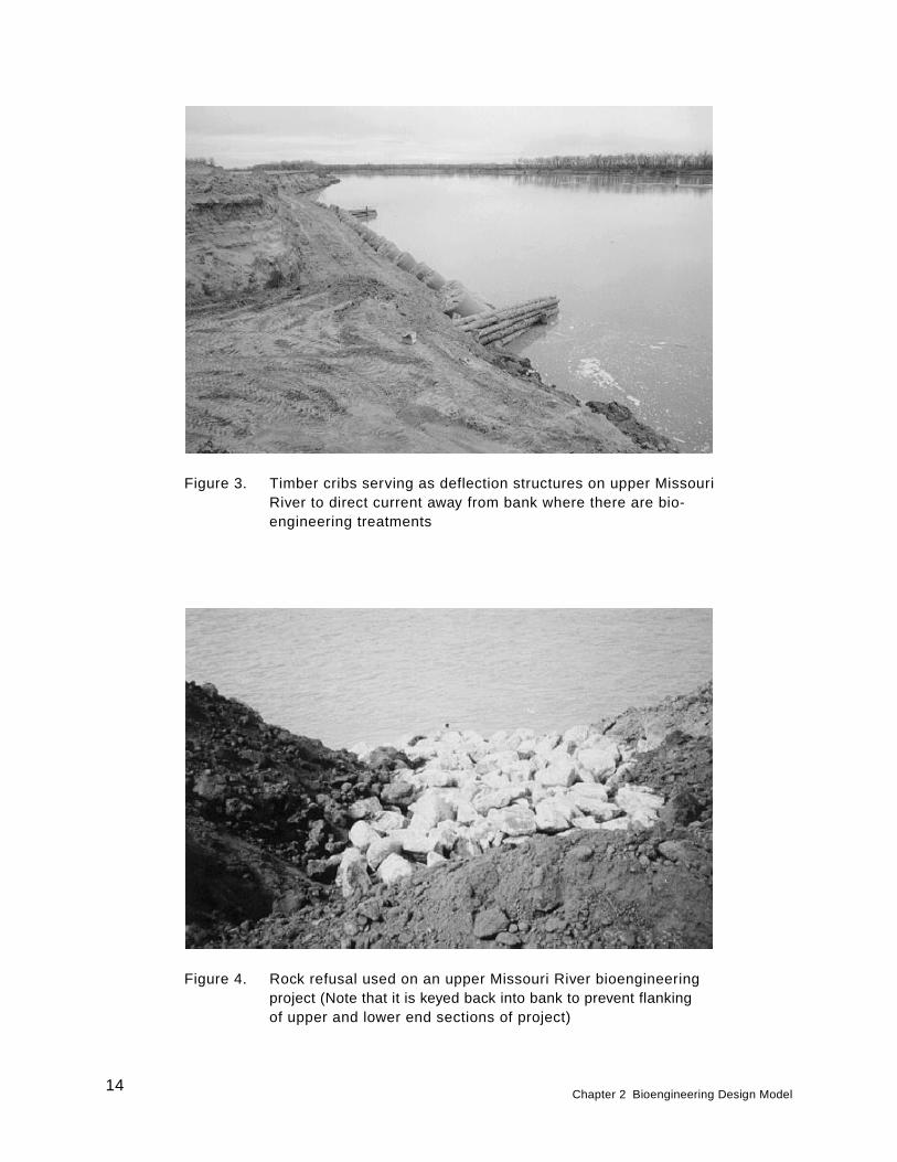
Figure 3. Timber cribs serving as deflection structures on upper MissouriRiver to direct current away from bank where there are bio-engineering treatments
Figure 4. Rock refusal used on an upper Missouri River bioengineeringproject (Note that it is keyed back into bank to prevent flankingof upper and lower end sections of project)
14Chapter 2 Bioengineering Design Model
Bioengineering by Zones
Plants should be positioned in various elevational zones of the bankbased on their ability to tolerate certain frequencies and durations of flood-ing and their attibutes of dissipating current and wave energies. Likewise,bioengineering fixes should be arranged by zone, which will be discussedbelow. The zone definitions given below correspond to those used by theU.S. Army Engineer District, Omaha, and have been used in preparingguidelines for the use of vegetation in streambank erosion control of theupper Missouri River (Logan et al. 1979). These zones are not preciseand distinct since stream levels vary daily and seasonally—they are onlyrelative and may be visualized as somewhat elastic depending on the bankgeometry. If one carefully copied nature in the planning process, plantspecies can be chosen that will adapt to that specific zone or microhabitat.Mallik and Harun (1993) lend credence to this zonal concept in a study onthe Neebing-McIntyre Floodway, parts of the Neebing and McIntyre RiverComplex near the Intercity area of Thunder Bay, Ontario, Canada. Theydescribe four microhabitats: bank slope, scarp face, above-water bench,and underwater depositional shelf. Each one had distinctively dominantplant species that generally correspond to the types of plants adapted forthis report. Figure 5 illustrates the location of each bank zone for the up-per Missouri River example. A description of each and the types of vege-tation and appropriate species examples associated with them is givenbelow. This zonal concept can be expanded to other streams to facilitateprescription of the erosion control treatment and plants to use at relativelocations on the streambank.
Toe zone
The toe zone is that portion of the bank between the bed and averagenormal stage. This zone is a zone of high stress and can often be undercutby currents. Undercutting here will likely result in bank failure unless pre-ventative or corrective measures are taken. This zone is often floodedgreater than 6 months of the year.
Figure 6 illustrates the plant species prescribed for each streambankzone on the upper Missouri River except for the toe zone. The toe zonewould likely have to be treated by some hard material, such as rock, stone,log revetments, cribs, or a durable material such as a geotextile roll (to bediscussed later).
Splash zone
The splash zone is that portion of the bank between normal high-waterand normal low-water flow rates. This and the toe zone are the zones ofhighest stress. The splash zone is exposed frequently to wave wash, ero-sive river currents, ice and debris movement, wet-dry cycles, and freezing-thawing cycles. This section of the bank would be inundated throughoutmost of the year (at least 6 months/year), but note that a large part of this
Chapter 2 Bioengineering Design Model15
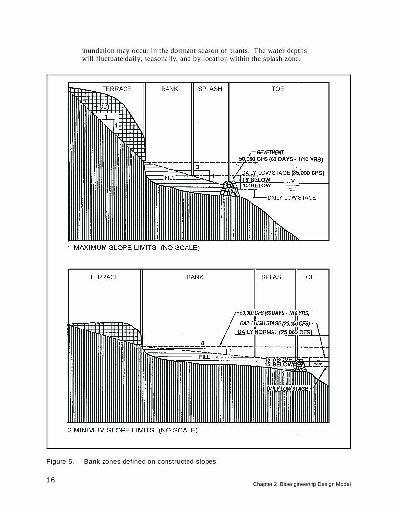
inundation may occur in the dormant season of plants. The water depthswill fluctuate daily, seasonally, and by location within the splash zone.
Figure 5. Bank zones defined on constructed slopes
16Chapter 2 Bioengineering Design Model
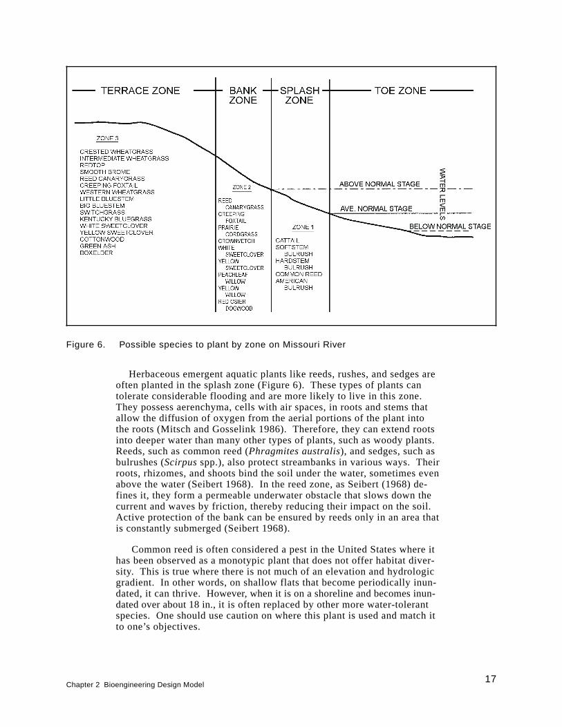
Herbaceous emergent aquatic plants like reeds, rushes, and sedges areoften planted in the splash zone (Figure 6). These types of plants cantolerate considerable flooding and are more likely to live in this zone.They possess aerenchyma, cells with air spaces, in roots and stems thatallow the diffusion of oxygen from the aerial portions of the plant intothe roots (Mitsch and Gosselink 1986). Therefore, they can extend rootsinto deeper water than many other types of plants, such as woody plants.Reeds, such as common reed (Phragmites australis), and sedges, such asbulrushes (Scirpusspp.), also protect streambanks in various ways. Theirroots, rhizomes, and shoots bind the soil under the water, sometimes evenabove the water (Seibert 1968). In the reed zone, as Seibert (1968) de-fines it, they form a permeable underwater obstacle that slows down thecurrent and waves by friction, thereby reducing their impact on the soil.Active protection of the bank can be ensured by reeds only in an area thatis constantly submerged (Seibert 1968).
Common reed is often considered a pest in the United States where ithas been observed as a monotypic plant that does not offer habitat diver-sity. This is true where there is not much of an elevation and hydrologicgradient. In other words, on shallow flats that become periodically inun-dated, it can thrive. However, when it is on a shoreline and becomes inun-dated over about 18 in., it is often replaced by other more water-tolerantspecies. One should use caution on where this plant is used and match itto one’s objectives.
Figure 6. Possible species to plant by zone on Missouri River
Chapter 2 Bioengineering Design Model17
Various wetland grasses, sedges, and other herbs were used in the splashzone as a part of a coir geotextile roll in an urban park setting in Allentown,PA. The main vegetative components of erosion control of the stream em-bankment are lake sedge (Carex lacustris),stubble sedge (C. stipata),andwoodland bulrush (Scirpus sylvaticus). Other minor components used fordiversity and color included rice cut-grass (Leersia oryzoides), othersedges (C. lata, C. lanuginosa, C. hysterina, and C. prasina), softstembulrush (Scirpus validus),blue flag iris (Iris versicolor),and monkeyflower (Mimulus ringens). The latter two species were provided primarilyfor additional diversity and color.1 Siegel reported that these plants, alongwith bioengineering methods such as the coir roll, stabilized a streambankthat was subjected to storm events. In fact, the methods were designed toaccentuate and enlarge the existing floodplain to act as a buffer zone forfloods associated with storms greater than the 25-year event (Siegel 1994).The vegetation list above only gives one example of types of species thatwere used for erosion control in the splash zone, i.e., flood-tolerant andfast-growing grasses and sedges. Care should be exercised in selectingspecies that are adapted to the project’s geographic area. Local universitybotanists and USDA Natural Resources Conservation Service (NRCS, for-merly Soil Conservation Service) district personnel can be consulted forsuitable species.
Herbaceous emergent aquatic plants, like those shown in Figure 6,must be used on a streambank that has a geometric shape conducive tosuch plants. Caution must be used on streams that have heavy silt loadsthat could suffocate plants. These plants must grow in fairly shallowwater, from +45 to -152 cm (Allen, Pierce, and Van Wormer 1989). Some-times, it is impossible or impractical to find or shape a stream to matchthose conditions. Then, flood-tolerant woody plants, like willow (Salixspp.), dogwood (Cornusspp.), and alder (Alnusspp.), are used in thesplash zone. Again, a good rule of thumb is to look at the natural systemand observe what is growing there and try to duplicate it.
Bank zone
The bank zone is that portion of the bank usually above the normalhigh-water level; yet, this site is exposed periodically to wave wash,erosive river currents, ice and debris movement, and traffic by animals orman. The site is inundated for at least a 60-day duration once every 2 to3 years. The water table in this zone frequently is close to the soil surfacedue to its closeness to the normal river level.
In the bank zone, both herbaceous (i.e., grasses, clovers, some sedges,and other herbs) and woody plants are used. These should still be floodtolerant and able to withstand partial to complete submergence for up toseveral weeks. Allen and Klimas (1986) list several grass and woody spe-cies that can tolerate from 4 to 8 weeks of complete inundation. This list
18Chapter 2 Bioengineering Design Model
1Unpublished Report, 1994, M. Siegel, “Biotechnical applications for wetland creation
and streambank restoration: Utilizing hydrophytic vegetation with fiber-schines for stabili-zation of a streambank and replicating the ecological functions of a wetland,” LehighCounty Conservation District, Allentown, PA.
should not be considered exhaustive, however. Whitlow and Harris(1979) provide a listing of flood-tolerant woody species and a few herba-ceous species by geographic area within the United States that can be usedin the bank zone.
Skeesick and Sheehan (1992) report on several other herbaceous andwoody plants that can withstand tens of feet of inundation over 3 to 4 monthsin two different reservoir situations in Oregon. These same species areoften found along streambanks. Local university botanists and plant mate-rial specialists within the NRCS should be consulted when seeking flood-tolerant plants . Various willows can be used in this zone, but they shouldbe shrublike willows such as sandbar willow (S. exigua) and basket willow(S. purpureavar. nana). Edminster, Atkinson, and McIntyre (1949) andEdminster (1949) describe successful use of basket willow for streams andrivers in the Northeast. Shrub-like willow, alder, and dogwood specieshave been used in Europe successfully (Seibert 1968). Red-osier dogwood(Cornus stolonifera) and silky dogwood (C. amomum) also have been usedin the Northeast (Edminster, Atkinson, and McIntyre 1949; Edminster 1949).Seibert (1968) notes that in periods of high water, the upper branches ofsuch shrubs reduce the speed of the current and thereby the erosive forceof the water. The branches of these have great resilience, springing backafter currents subside.
Terrace zone
The terrace zone is that portion of the bank inland from the bank zone;it is usually not subjected to erosive action of the river except during occa-sional flooding. This zone may include only the level area near the crestof the unaltered “high bank” or may include sharply sloping banks on highhills bordering the stream.
The terrace zone is less significant for bank protection because it isless often flooded, but can be easily eroded when it is flooded if vegeta-tion is not present. Vegetation in this zone is extremely important for in-tercepting floodwaters from overbank flooding, serving to reduce supersaturation and decrease weight of unstable banks through evapotranspira-tion processes and for tying the upper portion of the streambank togetherwith its soil-binding root network. Coppin and Richards (1990) provide adetailed explanation of plant evapotranspiration, but summarize by saying,“Apart from increasing the strength of soil by reducing its moisture con-tent, evapotranspiration by plants reduces the weight of the soil mass.This weight reduction can be important on vegetated slopes where the soilmay be potentially unstable.”
As denoted in Figure 6, the terrace zone can contain native grasses,herbs, shrubs, and trees that are less flood tolerant than those in the bankzone, but still somewhat flood tolerant. The tree species also becometaller and more massive. Trees are noted for their value in stabilizingbanks of streams and rivers (Seibert 1968; Leopold and Wolman 1957;Wolman and Leopold 1957; Lindsey et al. 1961; Sigafoos 1964). Thetrees have much deeper roots than grasses and shrubs and can hold the up-per bank together. The banks of some rivers are not eroded for durations
Chapter 2 Bioengineering Design Model19
of 100 to 200 years because heavy tree roots bind the alluvium of flood-plains (Leopold and Wolman 1957; Wolman and Leopold 1957; Sigafoos1964). A combination of trees, shrubs, and grasses in this zone will notonly serve as an integrated plant community for erosion control, but willimprove wildlife habitat diversity and aesthetic appeal.
Bioengineering Treatments
The entire streambank should be treated to furnish a maximum array ofplants capable of providing proper ground cover and root penetration forerosion protection, wildlife habitat, water quality improvement, and manyother benefits. At times, the planting sites or zones may be quite narrowin width or difficult to distinguish depending on the geomorphology of thestream. The entire bank in these cases should be treated as a systematicarrangement of plants and treatment practices.
Toe zone
This is the zone that will need to be protected from undercutting withtreatments such as stone or rock revetments, gabions, lunkers, log revet-ments, deflector dikes, cribs, rock and geotextile rolls, root wads, or acombination of materials. The zone rarely has vegetation employed in italone, but when vegetation is employed, it is used in combination with ma-terials that extend below the normal flow of water and above it. The prin-ciple is to keep high-velocity currents from undercutting the bank eitherthrough armoring the bank or deflecting the currents away from the site ofconcern. Vegetation can then be used either above the armor or in be-tween and above the deflecting structure.
Stone or rock revetments in a bioengineering application are used at thetoe in the zone below normal water levels and up to where normal waterlevels occur. Sometimes, the stone is extended above where normal flowlevels occur depending on the frequency and duration of flooding abovethis level. Then, vegetation is placed above it in a bioengineering applica-tion. Stream gauge information helps in making this judgement. Unfortu-nately, there are no set guidelines for how far up the bank to carry therevetment except to say that it should be applied below the scour zone upto at least the level where water runs the majority of the year. EngineeringManual 1110-2-1601, Change 1 (U.S. Army Corps of Engineers 1994)gives guidelines for riprap toe protection.
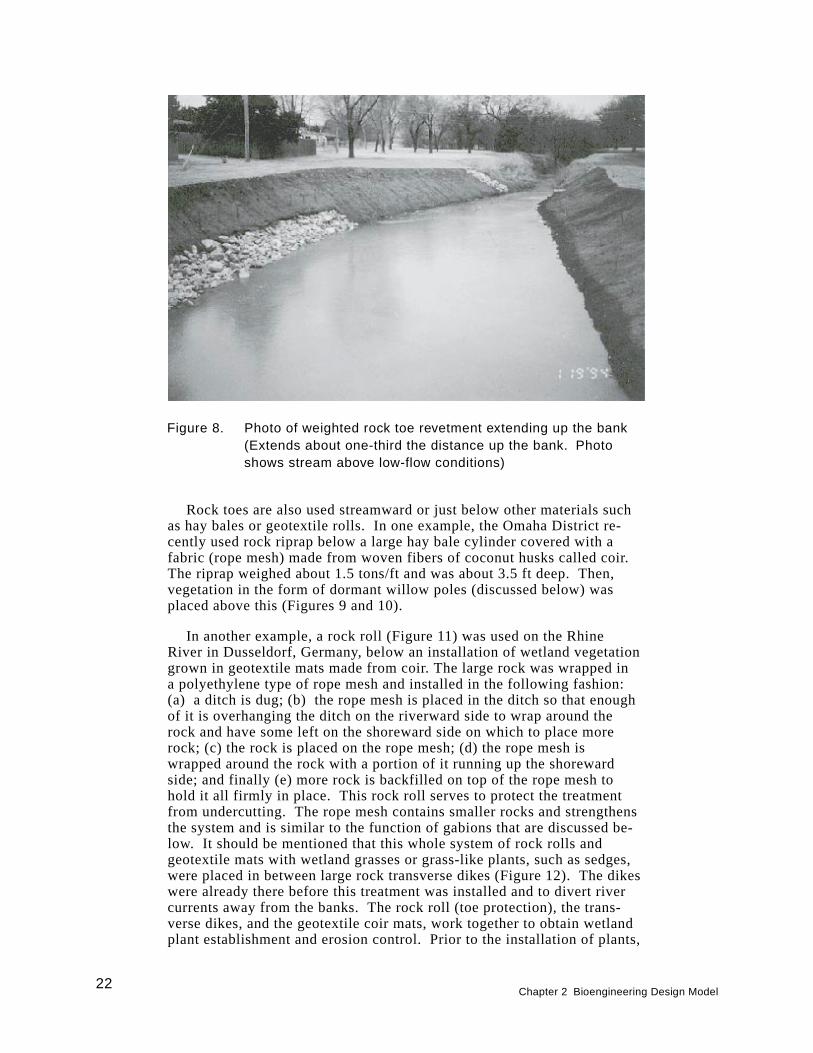
One such rock revetment for toe protection was used in conjunctionwith vegetation above it on Crutcho Creek, Tinker Air Force Base, Okla-homa (Figure 7). In this example, the creek is flashy and often reaches orexceeds the top of bank during the spring of each year for a few days.The rock toe extended from the bed to about one-third the height of thebank (Figure 8). This treatment has been successful in this type of settingafter several floods exceeding the top of the bank.
20Chapter 2 Bioengineering Design Model
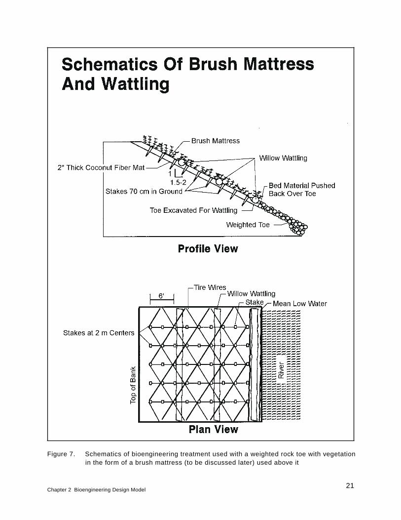
Figure 7. Schematics of bioengineering treatment used with a weighted rock toe with vegetationin the form of a brush mattress (to be discussed later) used above it
Chapter 2 Bioengineering Design Model21
Rock toes are also used streamward or just below other materials suchas hay bales or geotextile rolls. In one example, the Omaha District re-cently used rock riprap below a large hay bale cylinder covered with afabric (rope mesh) made from woven fibers of coconut husks called coir.The riprap weighed about 1.5 tons/ft and was about 3.5 ft deep. Then,vegetation in the form of dormant willow poles (discussed below) wasplaced above this (Figures 9 and 10).
In another example, a rock roll (Figure 11) was used on the RhineRiver in Dusseldorf, Germany, below an installation of wetland vegetationgrown in geotextile mats made from coir. The large rock was wrapped ina polyethylene type of rope mesh and installed in the following fashion:(a) a ditch is dug; (b) the rope mesh is placed in the ditch so that enoughof it is overhanging the ditch on the riverward side to wrap around therock and have some left on the shoreward side on which to place morerock; (c) the rock is placed on the rope mesh; (d) the rope mesh iswrapped around the rock with a portion of it running up the shorewardside; and finally (e) more rock is backfilled on top of the rope mesh tohold it all firmly in place. This rock roll serves to protect the treatmentfrom undercutting. The rope mesh contains smaller rocks and strengthensthe system and is similar to the function of gabions that are discussed be-low. It should be mentioned that this whole system of rock rolls andgeotextile mats with wetland grasses or grass-like plants, such as sedges,were placed in between large rock transverse dikes (Figure 12). The dikeswere already there before this treatment was installed and to divert rivercurrents away from the banks. The rock roll (toe protection), the trans-verse dikes, and the geotextile coir mats, work together to obtain wetlandplant establishment and erosion control. Prior to the installation of plants,
Figure 8. Photo of weighted rock toe revetment extending up the bank(Extends about one-third the distance up the bank. Photoshows stream above low-flow conditions)
22Chapter 2 Bioengineering Design Model
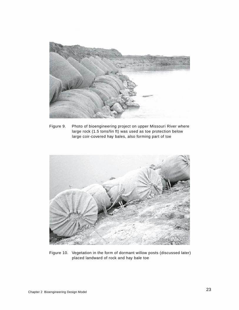
Figure 10. Vegetation in the form of dormant willow posts (discussed later)placed landward of rock and hay bale toe
Figure 9. Photo of bioengineering project on upper Missouri River wherelarge rock (1.5 tons/lin ft) was used as toe protection belowlarge coir-covered hay bales, also forming part of toe
Chapter 2 Bioengineering Design Model23
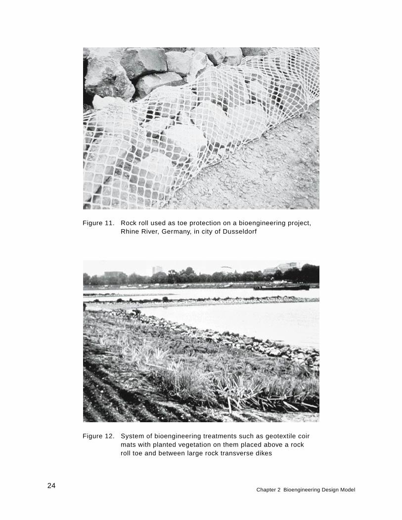
Figure 11. Rock roll used as toe protection on a bioengineering project,Rhine River, Germany, in city of Dusseldorf
Figure 12. System of bioengineering treatments such as geotextile coirmats with planted vegetation on them placed above a rockroll toe and between large rock transverse dikes
24Chapter 2 Bioengineering Design Model
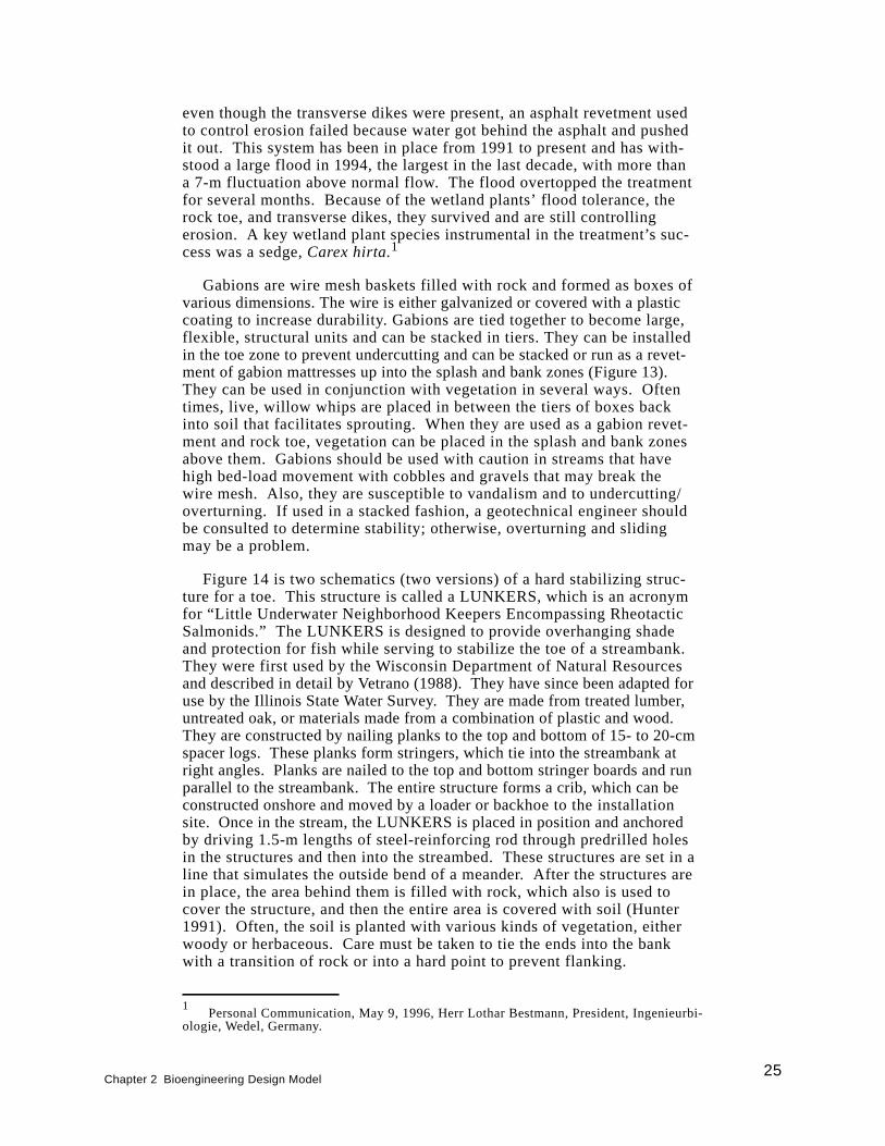
even though the transverse dikes were present, an asphalt revetment usedto control erosion failed because water got behind the asphalt and pushedit out. This system has been in place from 1991 to present and has with-stood a large flood in 1994, the largest in the last decade, with more thana 7-m fluctuation above normal flow. The flood overtopped the treatmentfor several months. Because of the wetland plants’ flood tolerance, therock toe, and transverse dikes, they survived and are still controllingerosion. A key wetland plant species instrumental in the treatment’s suc-cess was a sedge,Carex hirta.1
Gabions are wire mesh baskets filled with rock and formed as boxes ofvarious dimensions. The wire is either galvanized or covered with a plasticcoating to increase durability. Gabions are tied together to become large,flexible, structural units and can be stacked in tiers. They can be installedin the toe zone to prevent undercutting and can be stacked or run as a revet-ment of gabion mattresses up into the splash and bank zones (Figure 13).They can be used in conjunction with vegetation in several ways. Oftentimes, live, willow whips are placed in between the tiers of boxes backinto soil that facilitates sprouting. When they are used as a gabion revet-ment and rock toe, vegetation can be placed in the splash and bank zonesabove them. Gabions should be used with caution in streams that havehigh bed-load movement with cobbles and gravels that may break thewire mesh. Also, they are susceptible to vandalism and to undercutting/overturning. If used in a stacked fashion, a geotechnical engineer shouldbe consulted to determine stability; otherwise, overturning and slidingmay be a problem.
Figure 14 is two schematics (two versions) of a hard stabilizing struc-ture for a toe. This structure is called a LUNKERS, which is an acronymfor “Little Underwater Neighborhood Keepers Encompassing RheotacticSalmonids.” The LUNKERS is designed to provide overhanging shadeand protection for fish while serving to stabilize the toe of a streambank.They were first used by the Wisconsin Department of Natural Resourcesand described in detail by Vetrano (1988). They have since been adapted foruse by the Illinois State Water Survey. They are made from treated lumber,untreated oak, or materials made from a combination of plastic and wood.They are constructed by nailing planks to the top and bottom of 15- to 20-cmspacer logs. These planks form stringers, which tie into the streambank atright angles. Planks are nailed to the top and bottom stringer boards and runparallel to the streambank. The entire structure forms a crib, which can beconstructed onshore and moved by a loader or backhoe to the installationsite. Once in the stream, the LUNKERS is placed in position and anchoredby driving 1.5-m lengths of steel-reinforcing rod through predrilled holesin the structures and then into the streambed. These structures are set in aline that simulates the outside bend of a meander. After the structures arein place, the area behind them is filled with rock, which also is used tocover the structure, and then the entire area is covered with soil (Hunter1991). Often, the soil is planted with various kinds of vegetation, eitherwoody or herbaceous. Care must be taken to tie the ends into the bankwith a transition of rock or into a hard point to prevent flanking.
Chapter 2 Bioengineering Design Model25
1Personal Communication, May 9, 1996, Herr Lothar Bestmann, President, Ingenieurbi-
ologie, Wedel, Germany.
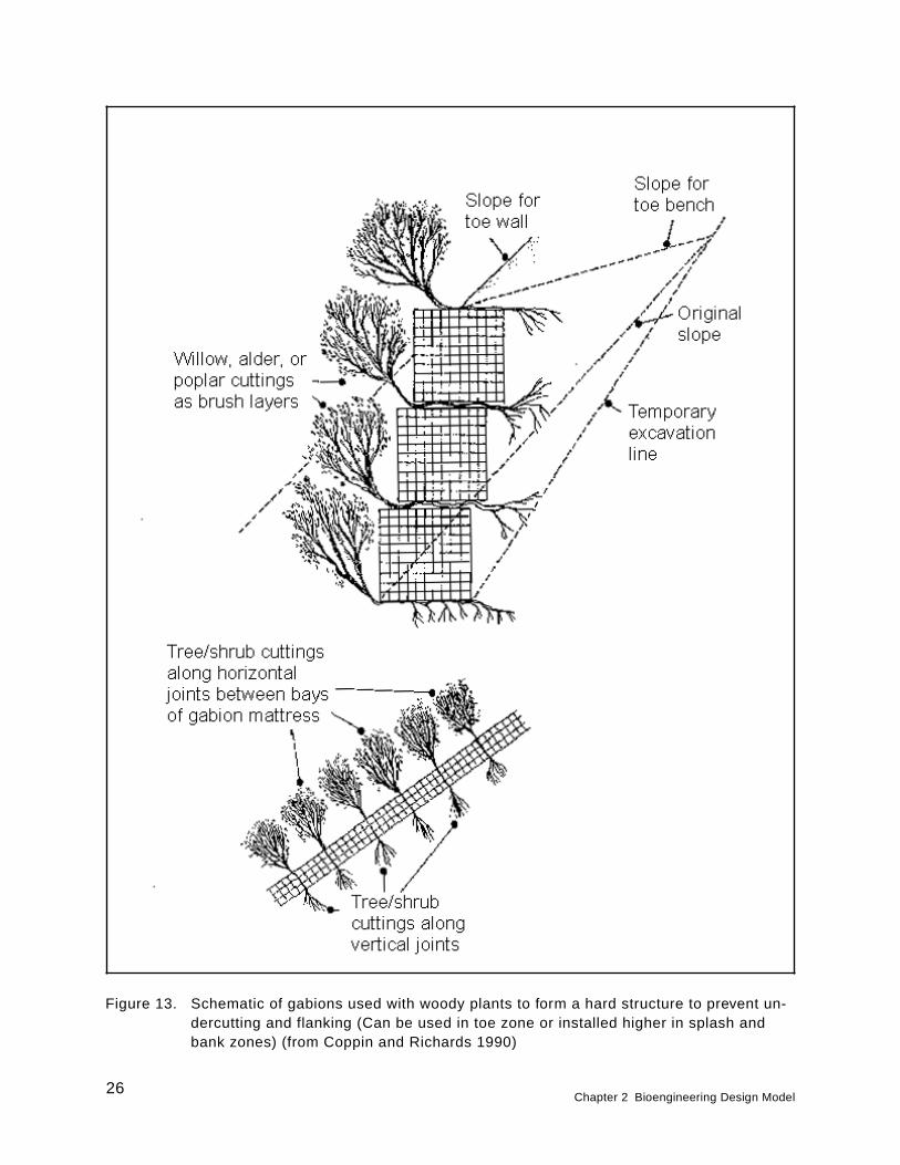
Figure 13. Schematic of gabions used with woody plants to form a hard structure to prevent un-dercutting and flanking (Can be used in toe zone or installed higher in splash andbank zones) (from Coppin and Richards 1990)
26Chapter 2 Bioengineering Design Model
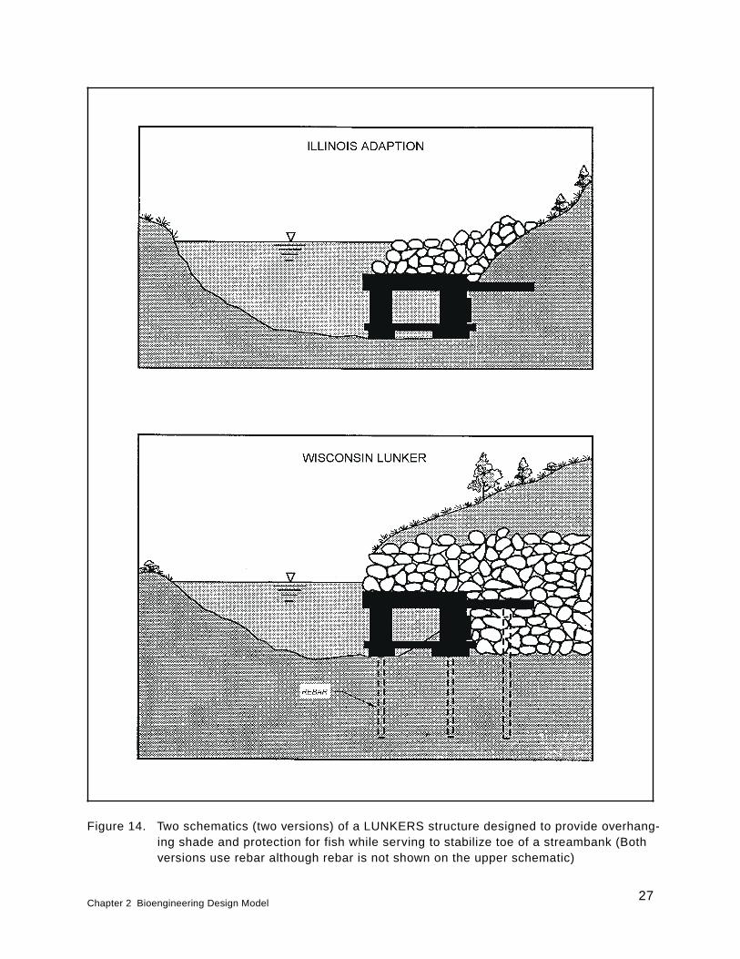
Figure 14. Two schematics (two versions) of a LUNKERS structure designed to provide overhang-ing shade and protection for fish while serving to stabilize toe of a streambank (Bothversions use rebar although rebar is not shown on the upper schematic)
Chapter 2 Bioengineering Design Model27
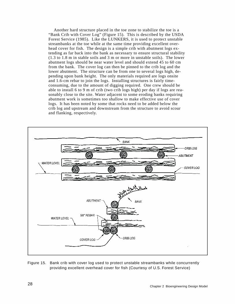
Another hard structure placed in the toe zone to stabilize the toe is a“Bank Crib with Cover Log” (Figure 15). This is described by the USDAForest Service (1985). Like the LUNKERS, it is used to protect unstablestreambanks at the toe while at the same time providing excellent over-head cover for fish. The design is a simple crib with abutment logs ex-tending as far back into the bank as necessary to ensure structural stability(1.3 to 1.8 m in stable soils and 3 m or more in unstable soils). The lowerabutment logs should be near water level and should extend 45 to 60 cmfrom the bank. The cover log can then be pinned to the crib log and thelower abutment. The structure can be from one to several logs high, de-pending upon bank height. The only materials required are logs onsiteand 1.6-cm rebar to join the logs. Installing structures is fairly time-consuming, due to the amount of digging required. One crew should beable to install 6 to 9 m of crib (two crib logs high) per day if logs are rea-sonably close to the site. Water adjacent to some eroding banks requiringabutment work is sometimes too shallow to make effective use of coverlogs. It has been noted by some that rocks need to be added below thecrib log and upstream and downstream from the structure to avoid scourand flanking, respectively.
Figure 15. Bank crib with cover log used to protect unstable streambanks while concurrentlyproviding excellent overhead cover for fish (Courtesy of U.S. Forest Service)
28Chapter 2 Bioengineering Design Model
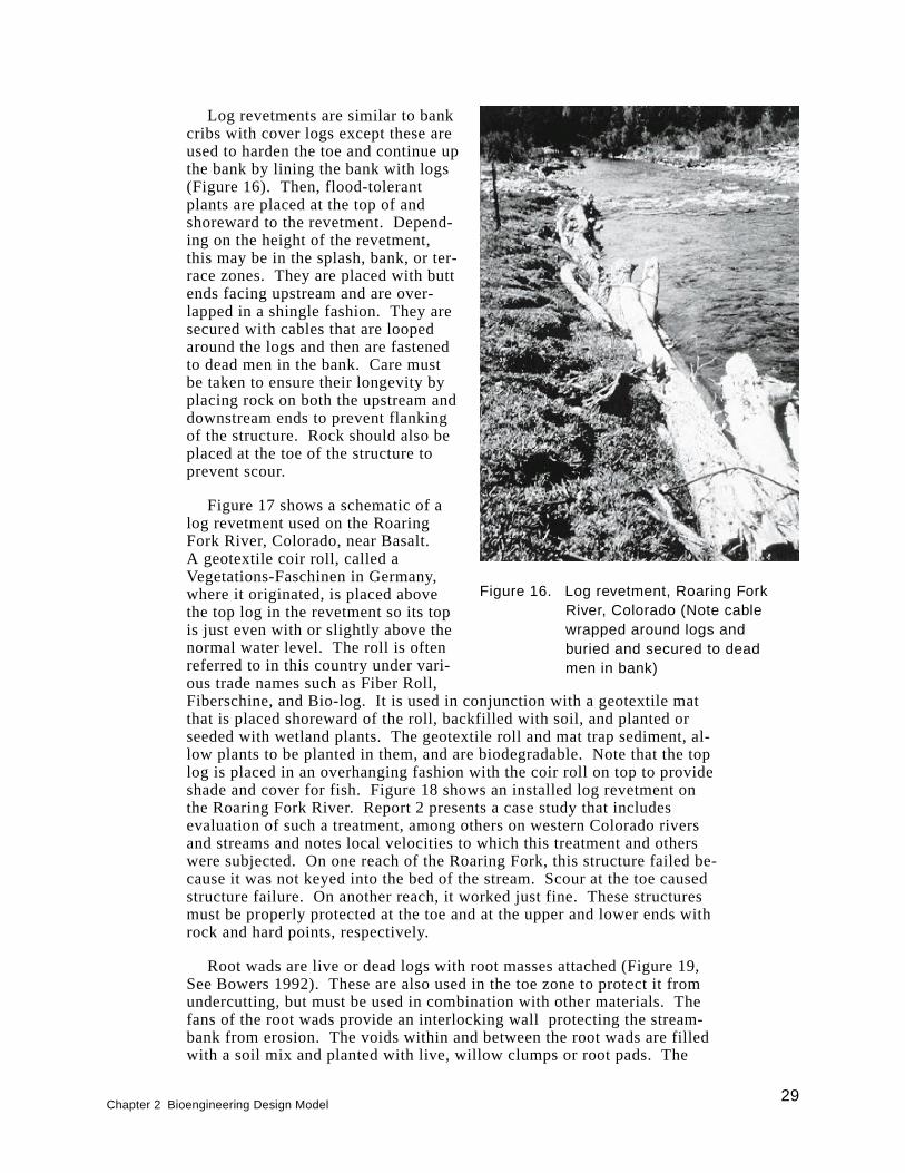
Log revetments are similar to bankcribs with cover logs except these areused to harden the toe and continue upthe bank by lining the bank with logs(Figure 16). Then, flood-tolerantplants are placed at the top of andshoreward to the revetment. Depend-ing on the height of the revetment,this may be in the splash, bank, or ter-race zones. They are placed with buttends facing upstream and are over-lapped in a shingle fashion. They aresecured with cables that are loopedaround the logs and then are fastenedto dead men in the bank. Care mustbe taken to ensure their longevity byplacing rock on both the upstream anddownstream ends to prevent flankingof the structure. Rock should also beplaced at the toe of the structure toprevent scour.
Figure 17 shows a schematic of alog revetment used on the RoaringFork River, Colorado, near Basalt.A geotextile coir roll, called aVegetations-Faschinen in Germany,where it originated, is placed abovethe top log in the revetment so its topis just even with or slightly above thenormal water level. The roll is oftenreferred to in this country under vari-ous trade names such as Fiber Roll,Fiberschine, and Bio-log. It is used in conjunction with a geotextile matthat is placed shoreward of the roll, backfilled with soil, and planted orseeded with wetland plants. The geotextile roll and mat trap sediment, al-low plants to be planted in them, and are biodegradable. Note that the toplog is placed in an overhanging fashion with the coir roll on top to provideshade and cover for fish. Figure 18 shows an installed log revetment onthe Roaring Fork River. Report 2 presents a case study that includesevaluation of such a treatment, among others on western Colorado riversand streams and notes local velocities to which this treatment and otherswere subjected. On one reach of the Roaring Fork, this structure failed be-cause it was not keyed into the bed of the stream. Scour at the toe causedstructure failure. On another reach, it worked just fine. These structuresmust be properly protected at the toe and at the upper and lower ends withrock and hard points, respectively.
Root wads are live or dead logs with root masses attached (Figure 19,See Bowers 1992). These are also used in the toe zone to protect it fromundercutting, but must be used in combination with other materials. Thefans of the root wads provide an interlocking wall protecting the stream-bank from erosion. The voids within and between the root wads are filledwith a soil mix and planted with live, willow clumps or root pads. The
Figure 16. Log revetment, Roaring ForkRiver, Colorado (Note cablewrapped around logs andburied and secured to deadmen in bank)
Chapter 2 Bioengineering Design Model29
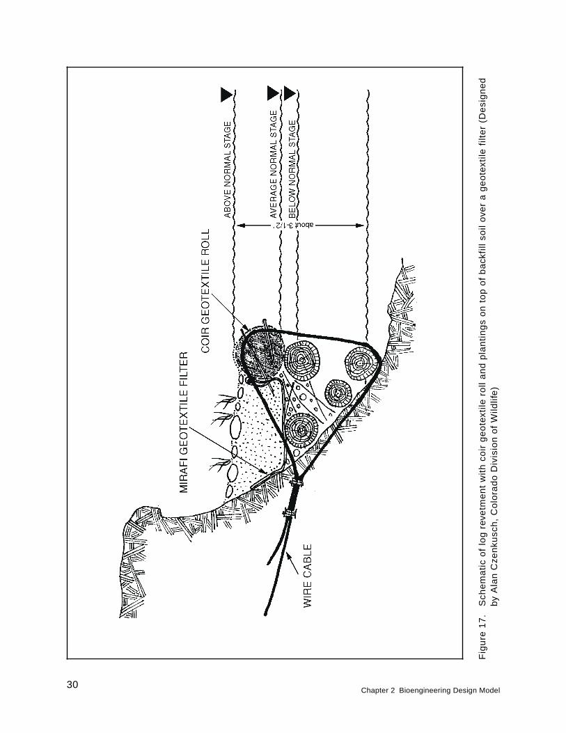
Fig
ure
17
.S
che
ma
tic
of
log
reve
tme
nt
wit
hco
irg
eo
text
ilero
lla
nd
pla
nti
ng
so
nto
po
fb
ack
fill
soil
ove
ra
ge
ote
xtile
filt
er
(De
sig
ne
dby
Ala
nC
zen
kusc
h,
Co
lora
do
Div
isio
no
fW
ildlif
e)
30Chapter 2 Bioengineering Design Model
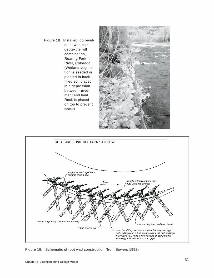
Figure 18. Installed log revet-ment with coirgeotextile rollcombination,Roaring ForkRiver, Colorado(Wetland vegeta-tion is seeded orplanted in back-filled soil placedin a depressionbetween revet-ment and land.Rock is placedon top to preventscour)
Figure 19. Schematic of root wad construction (from Bowers 1992)
Chapter 2 Bioengineering Design Model31
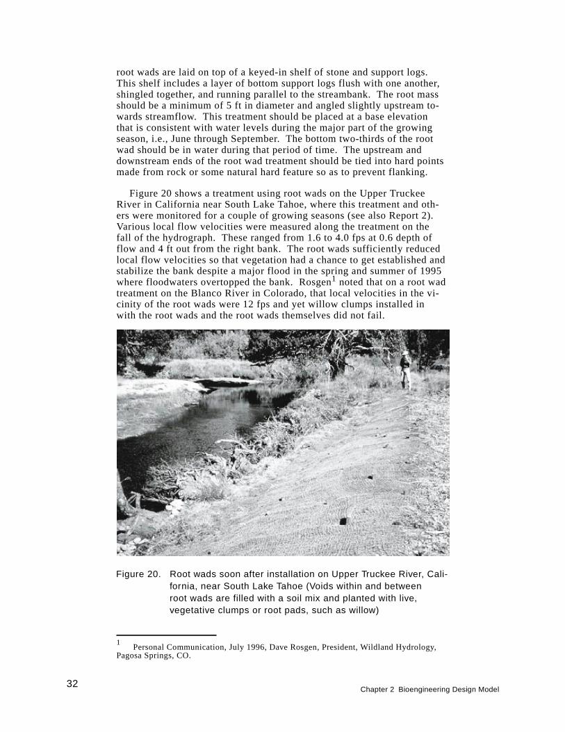
root wads are laid on top of a keyed-in shelf of stone and support logs.This shelf includes a layer of bottom support logs flush with one another,shingled together, and running parallel to the streambank. The root massshould be a minimum of 5 ft in diameter and angled slightly upstream to-wards streamflow. This treatment should be placed at a base elevationthat is consistent with water levels during the major part of the growingseason, i.e., June through September. The bottom two-thirds of the rootwad should be in water during that period of time. The upstream anddownstream ends of the root wad treatment should be tied into hard pointsmade from rock or some natural hard feature so as to prevent flanking.
Figure 20 shows a treatment using root wads on the Upper TruckeeRiver in California near South Lake Tahoe, where this treatment and oth-ers were monitored for a couple of growing seasons (see also Report 2).Various local flow velocities were measured along the treatment on thefall of the hydrograph. These ranged from 1.6 to 4.0 fps at 0.6 depth offlow and 4 ft out from the right bank. The root wads sufficiently reducedlocal flow velocities so that vegetation had a chance to get established andstabilize the bank despite a major flood in the spring and summer of 1995where floodwaters overtopped the bank. Rosgen1 noted that on a root wadtreatment on the Blanco River in Colorado, that local velocities in the vi-cinity of the root wads were 12 fps and yet willow clumps installed inwith the root wads and the root wads themselves did not fail.
Figure 20. Root wads soon after installation on Upper Truckee River, Cali-fornia, near South Lake Tahoe (Voids within and betweenroot wads are filled with a soil mix and planted with live,vegetative clumps or root pads, such as willow)
32Chapter 2 Bioengineering Design Model
1Personal Communication, July 1996, Dave Rosgen, President, Wildland Hydrology,
Pagosa Springs, CO.
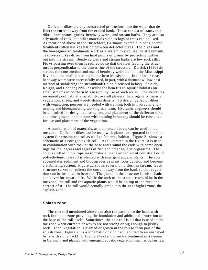
Deflector dikes are any constructed protrusions into the water that de-flect the current away from the eroded bank. These consist of transversedikes, hard points, groins, bendway weirs, and stream barbs. They are usu-ally made of rock, but other materials such as logs or trees can be used.As mentioned above in the Dusseldorf, Germany, example, bioengineeredtreatments often use vegetation between deflector dikes. The dikes andthe bioengineered treatments work as a system to stabilize the streambank.Transverse dikes differ from hard points or groins by projecting furtherout into the stream. Bendway weirs and stream barbs are low rock sills.Flows passing over them is redirected so that the flow leaving the struc-ture is perpendicular to the center line of the structure. Derrick (1996) de-scribes the construction and use of bendway weirs both on the MississippiRiver and on smaller streams in northern Mississippi. In the latter case,bendway weirs were successfully used, in part, with a dormant willow postmethod of stabilizing the streambank (to be discussed below). Shields,Knight, and Cooper (1995) describe the benefits to aquatic habitats onsmall streams in northern Mississippi by use of such weirs. The structuresincreased pool habitat availability, overall physical heterogeneity, riparianvegetation, shade, and woody debris density. To design deflector dikeswith vegetation, persons are needed with training both in hydraulic engi-neering and bioengineering working as a team. Hydraulic engineers shouldbe consulted for design, construction, and placement of the deflector dike,and bioengineers or someone with training in botany should be consultedfor use and placement of the vegetation.
A combination of materials, as mentioned above, can be used in thetoe zone. Deflector dikes can be used with plants incorporated in the dikesystem for erosion control as well as fisheries habitat. Figure 21 shows aschematic of a coir geotextile roll. As illustrated in the figure, it is usedin combination with rock at the base and around the ends with some open-ings for the ingress and egress of fish and other aquatic organisms. Thecoir is stuffed into a rope mesh material made either out of coir itself or ofpolyethylene. The roll is planted with emergent aquatic plants. The coiraccumulates sediment and biodegrades as plant roots develop and becomea stabilizing system. Figure 22 shows several on a German stream. Eachstructure serves to redirect the current away from the bank so that vegeta-tion can be installed in between. The plants in the structure furnish shadeand cover for aquatic life. While the rock of the structure would be in thetoe zone, the roll and the aquatic plants would be on top of the rock andabreast of it. The roll would actually grade into the next higher zone, the“splash zone.”
Splash zone
The coir roll mentioned above can also run parallel to the bank withrock in the toe zone providing the foundation and additional protection atthe base of the roll itself. Sometimes, the coir roll is all that is used in thetoe zone when currents or waves are not strong or big enough to justifyrock. Then, vegetation is planted or grown in the roll to form part of thesplash zone. Figure 23 is a schematic of a coir roll abutted to an unshapedbank with some backfill. Figure 24a-d show such a treatment in a streamin Germany and planted with emergent aquatic vegetation, such as bulrushes,
Chapter 2 Bioengineering Design Model33
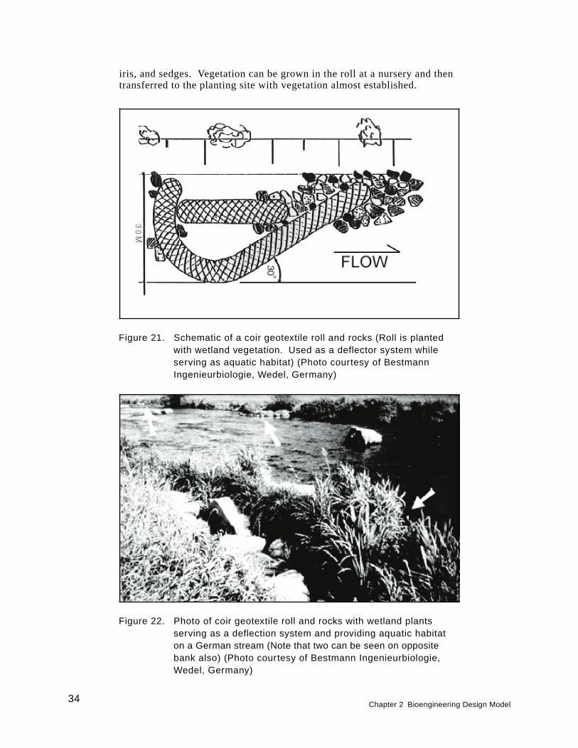
iris, and sedges. Vegetation can be grown in the roll at a nursery and thentransferred to the planting site with vegetation almost established.
Figure 21. Schematic of a coir geotextile roll and rocks (Roll is plantedwith wetland vegetation. Used as a deflector system whileserving as aquatic habitat) (Photo courtesy of BestmannIngenieurbiologie, Wedel, Germany)
Figure 22. Photo of coir geotextile roll and rocks with wetland plantsserving as a deflection system and providing aquatic habitaton a German stream (Note that two can be seen on oppositebank also) (Photo courtesy of Bestmann Ingenieurbiologie,Wedel, Germany)
34Chapter 2 Bioengineering Design Model
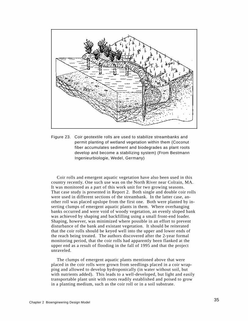
Coir rolls and emergent aquatic vegetation have also been used in thiscountry recently. One such use was on the North River near Colrain, MA.It was monitored as a part of this work unit for two growing seasons.That case study is presented in Report 2. Both single and double coir rollswere used in different sections of the streambank. In the latter case, an-other roll was placed upslope from the first one. Both were planted by in-serting clumps of emergent aquatic plants in them. Where overhangingbanks occurred and were void of woody vegetation, an evenly sloped bankwas achieved by shaping and backfilling using a small front-end loader.Shaping, however, was minimized where possible in an effort to preventdisturbance of the bank and existant vegetation. It should be reiteratedthat the coir rolls should be keyed well into the upper and lower ends ofthe reach being treated. The authors discovered after the 2-year formalmonitoring period, that the coir rolls had apparently been flanked at theupper end as a result of flooding in the fall of 1995 and that the projectunraveled.
The clumps of emergent aquatic plants mentioned above that wereplaced in the coir rolls were grown from seedlings placed in a coir wrap-ping and allowed to develop hydroponically (in water without soil, butwith nutrients added). This leads to a well-developed, but light and easilytransportable plant unit with roots readily established and poised to growin a planting medium, such as the coir roll or in a soil substrate.
Figure 23. Coir geotextile rolls are used to stabilize streambanks andpermit planting of wetland vegetation within them (Coconutfiber accumulates sediment and biodegrades as plant rootsdevelop and become a stabilizing system) (From BestmannIngenieurbiologie, Wedel, Germany)
Chapter 2 Bioengineering Design Model35
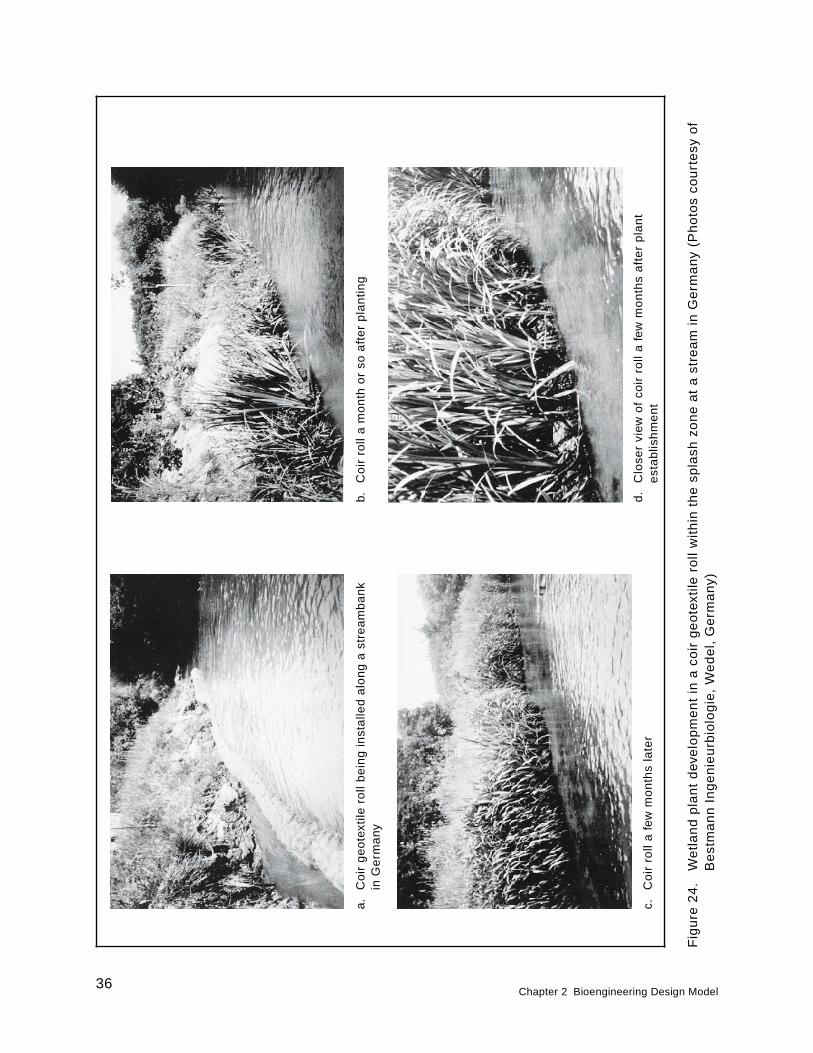
Fig
ure
24
.W
etl
an
dp
lan
td
eve
lop
me
nt
ina
coir
ge
ote
xtile
roll
with
inth
esp
lash
zon
ea
ta
stre
am
inG
erm
an
y(P
ho
tos
cou
rte
syo
fB
est
ma
nn
Ing
en
ieu
rbio
log
ie,
We
de
l,G
erm
an
y)
b.C
oir
roll
am
on
tho
rso
aft
er
pla
ntin
ga
.C
oir
ge
ote
xtile
roll
be
ing
inst
alle
da
lon
ga
stre
am
ba
nk
inG
erm
any
d.
Clo
ser
view
of
coir
roll
afe
wm
on
ths
aft
er
pla
nt
est
abl
ish
me
nt
c.C
oir
roll
afe
wm
on
ths
late
r
36Chapter 2 Bioengineering Design Model
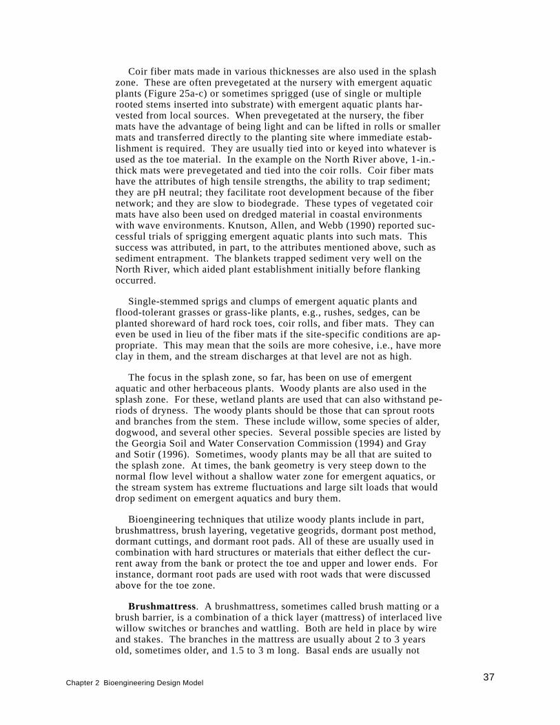
Coir fiber mats made in various thicknesses are also used in the splashzone. These are often prevegetated at the nursery with emergent aquaticplants (Figure 25a-c) or sometimes sprigged (use of single or multiplerooted stems inserted into substrate) with emergent aquatic plants har-vested from local sources. When prevegetated at the nursery, the fibermats have the advantage of being light and can be lifted in rolls or smallermats and transferred directly to the planting site where immediate estab-lishment is required. They are usually tied into or keyed into whatever isused as the toe material. In the example on the North River above, 1-in.-thick mats were prevegetated and tied into the coir rolls. Coir fiber matshave the attributes of high tensile strengths, the ability to trap sediment;they are pH neutral; they facilitate root development because of the fibernetwork; and they are slow to biodegrade. These types of vegetated coirmats have also been used on dredged material in coastal environmentswith wave environments. Knutson, Allen, and Webb (1990) reported suc-cessful trials of sprigging emergent aquatic plants into such mats. Thissuccess was attributed, in part, to the attributes mentioned above, such assediment entrapment. The blankets trapped sediment very well on theNorth River, which aided plant establishment initially before flankingoccurred.
Single-stemmed sprigs and clumps of emergent aquatic plants andflood-tolerant grasses or grass-like plants, e.g., rushes, sedges, can beplanted shoreward of hard rock toes, coir rolls, and fiber mats. They caneven be used in lieu of the fiber mats if the site-specific conditions are ap-propriate. This may mean that the soils are more cohesive, i.e., have moreclay in them, and the stream discharges at that level are not as high.
The focus in the splash zone, so far, has been on use of emergentaquatic and other herbaceous plants. Woody plants are also used in thesplash zone. For these, wetland plants are used that can also withstand pe-riods of dryness. The woody plants should be those that can sprout rootsand branches from the stem. These include willow, some species of alder,dogwood, and several other species. Several possible species are listed bythe Georgia Soil and Water Conservation Commission (1994) and Grayand Sotir (1996). Sometimes, woody plants may be all that are suited tothe splash zone. At times, the bank geometry is very steep down to thenormal flow level without a shallow water zone for emergent aquatics, orthe stream system has extreme fluctuations and large silt loads that woulddrop sediment on emergent aquatics and bury them.
Bioengineering techniques that utilize woody plants include in part,brushmattress, brush layering, vegetative geogrids, dormant post method,dormant cuttings, and dormant root pads. All of these are usually used incombination with hard structures or materials that either deflect the cur-rent away from the bank or protect the toe and upper and lower ends. Forinstance, dormant root pads are used with root wads that were discussedabove for the toe zone.
Brushmattress. A brushmattress, sometimes called brush matting or abrush barrier, is a combination of a thick layer (mattress) of interlaced livewillow switches or branches and wattling. Both are held in place by wireand stakes. The branches in the mattress are usually about 2 to 3 yearsold, sometimes older, and 1.5 to 3 m long. Basal ends are usually not
Chapter 2 Bioengineering Design Model37
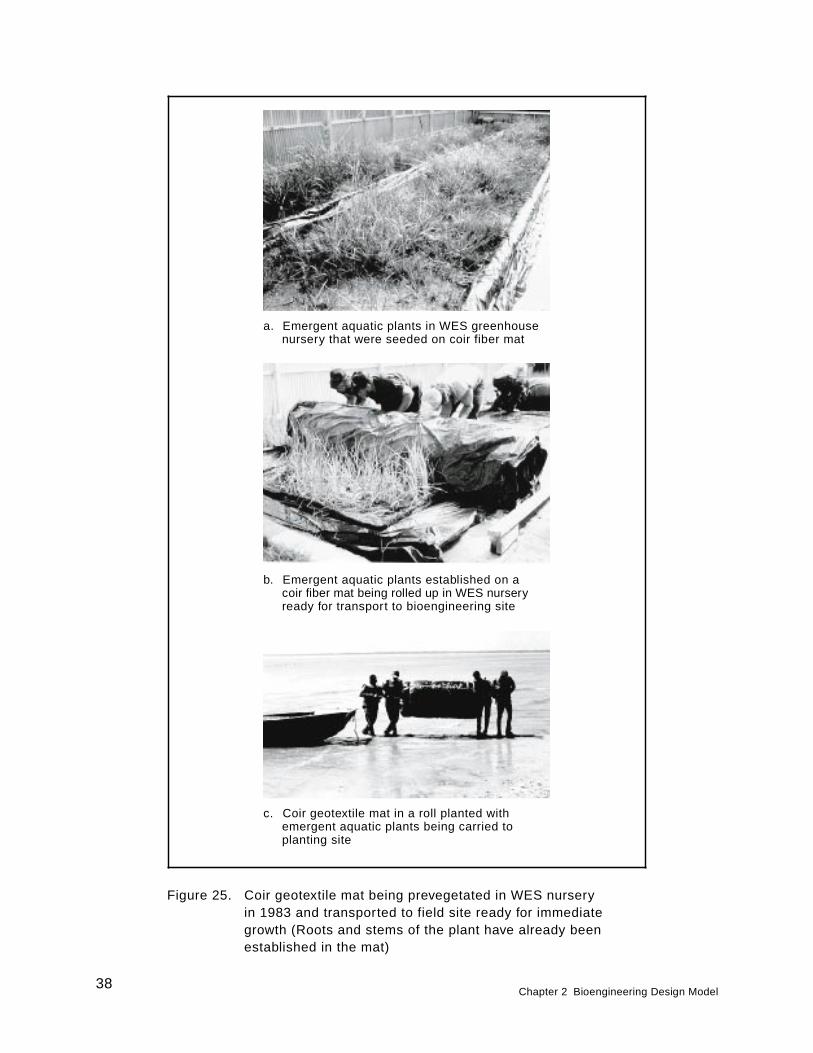
Figure 25. Coir geotextile mat being prevegetated in WES nurseryin 1983 and transported to field site ready for immediategrowth (Roots and stems of the plant have already beenestablished in the mat)
a. Emergent aquatic plants in WES greenhousenursery that were seeded on coir fiber mat
b. Emergent aquatic plants established on acoir fiber mat being rolled up in WES nurseryready for transport to bioengineering site
c. Coir geotextile mat in a roll planted withemergent aquatic plants being carried toplanting site
38Chapter 2 Bioengineering Design Model
more than about 3.5 cm in diameter. They are placed perpendicular to thebank with their basal ends inserted into a trench at the bottom of the slopein the splash zone, just above any toe protection, such as a rock toe. Thebranches are cut from live willow plants and kept moist until planting.The willow branches will sprout after planting, but care should be taken toobtain and plant them in the dormant period, either in the late fall afterbud set or in the early spring before bud break. A compacted layer ofbranches 10 to 15 cm thick is used and is held in place by either wovenwire or tie-wire. Wedge-shaped construction stakes (2 by 4 by 24 in. to2 by 4 by 36 in., diagonal cut) are used to hold the wire in place. A gaugeand type suitable for tie-wire is No. 9 or 10 galvanized annealed. It is runperpendicular to the branches and also diagonally from stake to stake andusually tied by use of a clove-hitch. If woven wire is used, it should be astrong welded wire (2- by 4-in. mesh). The wedged-shape stakes aredriven firmly through the wire as it is stretched over the mattress to hold itin place. The wedge of the stake actually compresses the wire to hold thebrush down. Wattling is a cigar-shaped bundle of live, shrubby materialmade from species that root very quickly from the stem, such as willowand some species of dogwood and alder. These bundles are laid over thebasal ends of the brushmattress material that was placed in the ditch andstaked. The procedure of making wattling bundles and installing themover the brushmattress material is presented in more detail below (Theseprocedures are modified after Leiser (1994)).
Wattling bundles may vary in length, depending on materials available.Bundles taper at the ends; this is achieved by alternately (randomly) plac-ing each stem so that about one-half of the basal ends are at each end ofthe bundle. When compressed firmly and tied, each bundle is about 15 to20 cm in diameter in the middle. Bundles should be tied with either hempbinder twine or can be fastened and compressed by wrapping “pigtails”around the bundle. Pigtails are commonly used to fasten rebar together.If tied with binder twine, a minimum of two wraps should be used in com-bination with a nonslipping knot, such as a square knot. Tying of bundlesshould be done on about 38-cm centers. Wattling bundles should bestaked firmly in place with vertical stakes on the downhill side of the wat-tling not more than 90 cm on center and with the wedge of the stake point-ing upslope. Also, stakes should be installed through the bundles at aboutthe same distance, but slightly offset and turned around so their wedgepoints downslope. In this way, the wedged stakes, in tandem, compressthe wattling very firmly. Where bundles overlap, an additional pair ofstakes should be used at the midpoint of the overlap. The overlap shouldbe staked with one pair of stakes through the ends of both bundles whileon the inside of the end tie of each bundle. Figure 26a-b shows a sche-matic of a brushmattress and wattling. Figure 27a-c shows a sequenceof installing a brushmattress with wattling at a workshop. It should benoted that because of the workshop setting at a mild time of the year,nondormant vegetative material is being used. Normally, one wouldpreferably use dormant material.
Both brushmattress and wattling should be covered immediately withsoil and tamped. Soil should be worked into both the brushmattress andwattling by by both tamping and walking on it. All but the edges of thebrushmattress should be covered with soil, and about 75 percent of the
Chapter 2 Bioengineering Design Model39
wattling should be covered leaving some of each exposed to facilitatesprouting of stems rather than roots.
Figure 26. Schematics of brushmattress and wattling combination (from Leiser 1983)
a. Profile view
b. Plan view
40Chapter 2 Bioengineering Design Model
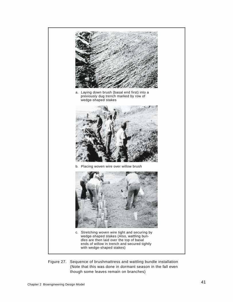
Figure 27. Sequence of brushmattress and wattling bundle installation(Note that this was done in dormant season in the fall eventhough some leaves remain on branches)
a. Laying down brush (basal end first) into apreviously dug trench marked by row ofwedge-shaped stakes
b. Placing woven wire over willow brush
c. Stretching woven wire tight and securing bywedge-shaped stakes (Also, wattling bun-dles are then laid over the top of basalends of willow in trench and secured tightlywith wedge-shaped stakes)
Chapter 2 Bioengineering Design Model41
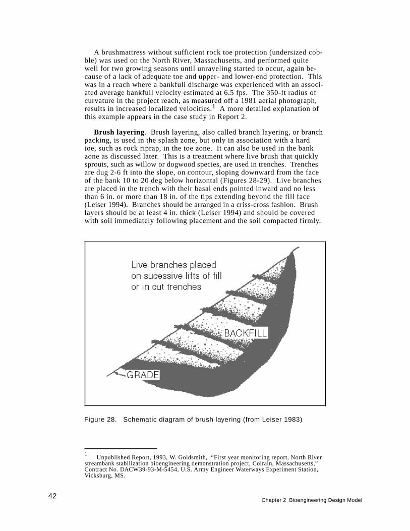
A brushmattress without sufficient rock toe protection (undersized cob-ble) was used on the North River, Massachusetts, and performed quitewell for two growing seasons until unraveling started to occur, again be-cause of a lack of adequate toe and upper- and lower-end protection. Thiswas in a reach where a bankfull discharge was experienced with an associ-ated average bankfull velocity estimated at 6.5 fps. The 350-ft radius ofcurvature in the project reach, as measured off a 1981 aerial photograph,results in increased localized velocities.1 A more detailed explanation ofthis example appears in the case study in Report 2.
Brush layering. Brush layering, also called branch layering, or branchpacking, is used in the splash zone, but only in association with a hardtoe, such as rock riprap, in the toe zone. It can also be used in the bankzone as discussed later. This is a treatment where live brush that quicklysprouts, such as willow or dogwood species, are used in trenches. Trenchesare dug 2-6 ft into the slope, on contour, sloping downward from the faceof the bank 10 to 20 deg below horizontal (Figures 28-29). Live branchesare placed in the trench with their basal ends pointed inward and no lessthan 6 in. or more than 18 in. of the tips extending beyond the fill face(Leiser 1994). Branches should be arranged in a criss-cross fashion. Brushlayers should be at least 4 in. thick (Leiser 1994) and should be coveredwith soil immediately following placement and the soil compacted firmly.
Figure 28. Schematic diagram of brush layering (from Leiser 1983)
42Chapter 2 Bioengineering Design Model
1Unpublished Report, 1993, W. Goldsmith, “First year monitoring report, North River
streambank stabilization bioengineering demonstration project, Colrain, Massachusetts,”Contract No. DACW39-93-M-5454, U.S. Army Engineer Waterways Experiment Station,Vicksburg, MS.
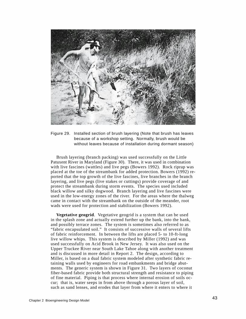
Brush layering (branch packing) was used successfully on the LittlePatuxent River in Maryland (Figure 30). There, it was used in combinationwith live fascines (wattles) and live pegs (Bowers 1992). Rock riprap wasplaced at the toe of the streambank for added protection. Bowers (1992) re-ported that the top growth of the live fascines, live branches in the branchlayering, and live pegs (live stakes or cuttings) provide coverage of andprotect the streambank during storm events. The species used includedblack willow and silky dogwood. Branch layering and live fascines wereused in the low-energy zones of the river. For the areas where the thalwegcame in contact with the streambank on the outside of the meander, rootwads were used for protection and stabilization (Bowers 1992).
Vegetative geogrid. Vegetative geogrid is a system that can be usedin the splash zone and actually extend further up the bank, into the bank,and possibly terrace zones. The system is sometimes also referred to as“fabric encapsulated soil.” It consists of successive walls of several liftsof fabric reinforcement. In between the lifts are placed 5- to 10-ft-longlive willow whips. This system is described by Miller (1992) and wasused successfully on Acid Brook in New Jersey. It was also used on theUpper Truckee River near South Lake Tahoe along with another treatmentand is discussed in more detail in Report 2. The design, according toMiller, is based on a dual fabric system modeled after synthetic fabric re-taining walls used by engineers for road embankments and bridge abut-ments. The generic system is shown in Figure 31. Two layers of coconutfiber-based fabric provide both structural strength and resistance to pipingof fine material. Piping is that process where internal erosion of soils oc-cur; that is, water seeps in from above through a porous layer of soil,such as sand lenses, and erodes that layer from where it enters to where it
Figure 29. Installed section of brush layering (Note that brush has leavesbecause of a workshop setting. Normally, brush would bewithout leaves because of installation during dormant season)
Chapter 2 Bioengineering Design Model43
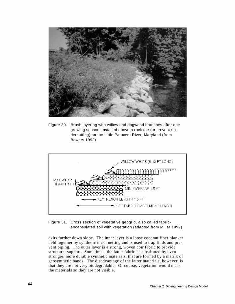
exits further down slope. The inner layer is a loose coconut fiber blanketheld together by synthetic mesh netting and is used to trap finds and pre-vent piping. The outer layer is a strong, woven coir fabric to providestructural support. Sometimes, the latter fabric is substituted by evenstronger, more durable synthetic materials, that are formed by a matrix ofgeosynthetic bands. The disadvantage of the latter materials, however, isthat they are not very biodegradable. Of course, vegetation would maskthe materials so they are not visible.
Figure 30. Brush layering with willow and dogwood branches after onegrowing season; installed above a rock toe (to prevent un-dercutting) on the Little Patuxent River, Maryland (fromBowers 1992)
Figure 31. Cross section of vegetative geogrid, also called fabric-encapsulated soil with vegetation (adapted from Miller 1992)
44Chapter 2 Bioengineering Design Model
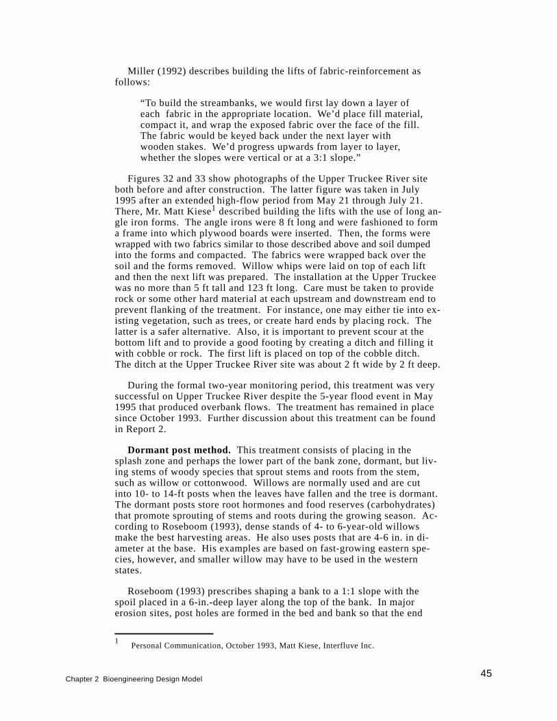
Miller (1992) describes building the lifts of fabric-reinforcement asfollows:
“To build the streambanks, we would first lay down a layer ofeach fabric in the appropriate location. We’d place fill material,compact it, and wrap the exposed fabric over the face of the fill.The fabric would be keyed back under the next layer withwooden stakes. We’d progress upwards from layer to layer,whether the slopes were vertical or at a 3:1 slope.”
Figures 32 and 33 show photographs of the Upper Truckee River siteboth before and after construction. The latter figure was taken in July1995 after an extended high-flow period from May 21 through July 21.There, Mr. Matt Kiese1 described building the lifts with the use of long an-gle iron forms. The angle irons were 8 ft long and were fashioned to forma frame into which plywood boards were inserted. Then, the forms werewrapped with two fabrics similar to those described above and soil dumpedinto the forms and compacted. The fabrics were wrapped back over thesoil and the forms removed. Willow whips were laid on top of each liftand then the next lift was prepared. The installation at the Upper Truckeewas no more than 5 ft tall and 123 ft long. Care must be taken to providerock or some other hard material at each upstream and downstream end toprevent flanking of the treatment. For instance, one may either tie into ex-isting vegetation, such as trees, or create hard ends by placing rock. Thelatter is a safer alternative. Also, it is important to prevent scour at thebottom lift and to provide a good footing by creating a ditch and filling itwith cobble or rock. The first lift is placed on top of the cobble ditch.The ditch at the Upper Truckee River site was about 2 ft wide by 2 ft deep.
During the formal two-year monitoring period, this treatment was verysuccessful on Upper Truckee River despite the 5-year flood event in May1995 that produced overbank flows. The treatment has remained in placesince October 1993. Further discussion about this treatment can be foundin Report 2.
Dormant post method. This treatment consists of placing in thesplash zone and perhaps the lower part of the bank zone, dormant, but liv-ing stems of woody species that sprout stems and roots from the stem,such as willow or cottonwood. Willows are normally used and are cutinto 10- to 14-ft posts when the leaves have fallen and the tree is dormant.The dormant posts store root hormones and food reserves (carbohydrates)that promote sprouting of stems and roots during the growing season. Ac-cording to Roseboom (1993), dense stands of 4- to 6-year-old willowsmake the best harvesting areas. He also uses posts that are 4-6 in. in di-ameter at the base. His examples are based on fast-growing eastern spe-cies, however, and smaller willow may have to be used in the westernstates.
Roseboom (1993) prescribes shaping a bank to a 1:1 slope with thespoil placed in a 6-in.-deep layer along the top of the bank. In majorerosion sites, post holes are formed in the bed and bank so that the end
Chapter 2 Bioengineering Design Model45
1Personal Communication, October 1993, Matt Kiese, Interfluve Inc.
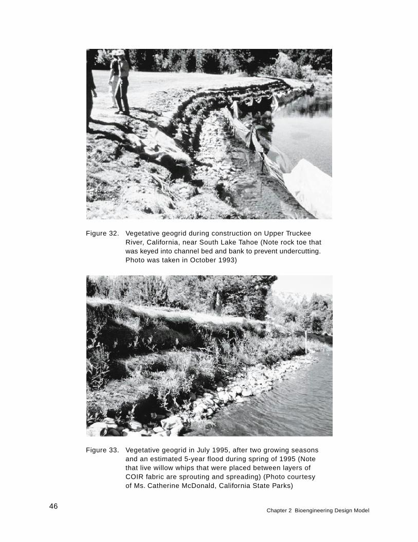
Figure 32. Vegetative geogrid during construction on Upper TruckeeRiver, California, near South Lake Tahoe (Note rock toe thatwas keyed into channel bed and bank to prevent undercutting.Photo was taken in October 1993)
Figure 33. Vegetative geogrid in July 1995, after two growing seasonsand an estimated 5-year flood during spring of 1995 (Notethat live willow whips that were placed between layers ofCOIR fabric are sprouting and spreading) (Photo courtesyof Ms. Catherine McDonald, California State Parks)
46Chapter 2 Bioengineering Design Model

of the post is 2 ft below maximum streambed scour (that portion of thestreambed that is subject to movement). Hoag (1993) suggested that forbank stabilization, the cutting (post) should extend 2-3 ft above ground soas it leafs out, it can provide immediate bank erosion protection. He alsorecommended the cutting should be planted as much as 3-5 ft into the ground.If they are not this deep, moving water can erode around the cutting andrip it out of the ground. Roseboom places the posts 4 ft apart up thestreambank. The posts in one row are offset from the posts in adjacentrows.
Both Roseboom (1993) and Hoag (1993) advised that willow postsshould be long enough and placed deep enough to reach wet soil duringdry summers. Hoag (1993) noted that plantings can occur at the waterline, up the bank, and on top of bank in relatively dry soil, as long as cut-tings are long enough to reach into the mid-summer water table.
An excavator that is either fitted with a long, steel ram or an auger istypically required for installation. Roseboom (1993) reported that a steelram on an excavator boom is more efficient at depths of 6 ft in clay soils.In contrast, an auger on an excavator boom forms deeper and longer last-ing holes in stoney or sandy streambeds. The ram on the excavator is forcreating a pilot hole in which to place the willow post. The willow post isfitted with a cap that goes over the post, and then the heel of the bucket onthe excavator is used to push the post down into the hole. Care must betaken to ensure that the post comes in contact with the soil so that no airpockets exist. In the case of the auger, this can be done by backfilling thesides of the hole in lifts and then tamping. In the case of the ram, the ramcan be placed out a few inches from the post and run along the side of itinto the soil so as to close the hole containing the post, especially towardthe bottom of the hole.
Roseboom (1993) reported that in larger streams with noncohesive sandbanks, large cedar trees cabled to the willow posts along the toe of thebank can reduce toe erosion. The cedars not only reduce bank scour whileroot systems are growing, but retain moisture during drought periods. An-other material used for the same purpose is a coir roll mentioned earlier.In addition to trapping sediment, the coir roll can be planted with eitheremergent aquatic vegetation or other willow cuttings. The cedar trees andthe coir roll were used in combination with willow poles on Court Creek,Illinois, along a 600-ft reach. Figures 34 and 35, respectively, illustratework in progress and bank conditions 4 months after planting. This is de-scribed in a case study in Report 2. Velocities were measured at this siteduring a major 1995 flood and ranged between 1.23 to 3.11 fps. Theywere measured at distances immediately in front of the treatment to 3.5 ftin front and at both the surface and 0.6 ft of stream depth. It is suspectedthat the willow contributed substantially to reduced velocities near thebank.
Hoag (1994a) and Hoag (1994b) provided specifications for and de-scription of another type of implement that is used to make a pilot hole forthe dormant willow post. It is called “The Stinger” and has been used bythe NRCS and the Bureau of Reclamation for establishing willow in rip-rapped revetments on shorelines of reservoirs and streambanks. Accordingto Hoag (1994b), woody vegetation has been planted in rock riprap by
Chapter 2 Bioengineering Design Model47
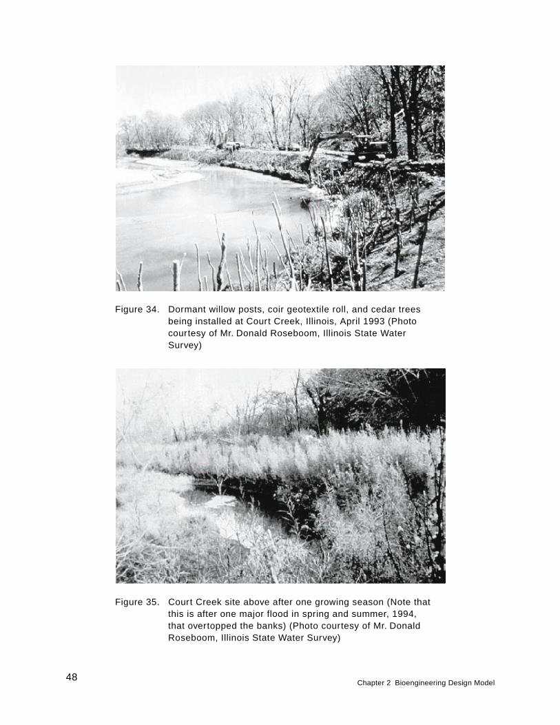
Figure 34. Dormant willow posts, coir geotextile roll, and cedar treesbeing installed at Court Creek, Illinois, April 1993 (Photocourtesy of Mr. Donald Roseboom, Illinois State WaterSurvey)
Figure 35. Court Creek site above after one growing season (Note thatthis is after one major flood in spring and summer, 1994,that overtopped the banks) (Photo courtesy of Mr. DonaldRoseboom, Illinois State Water Survey)
48Chapter 2 Bioengineering Design Model
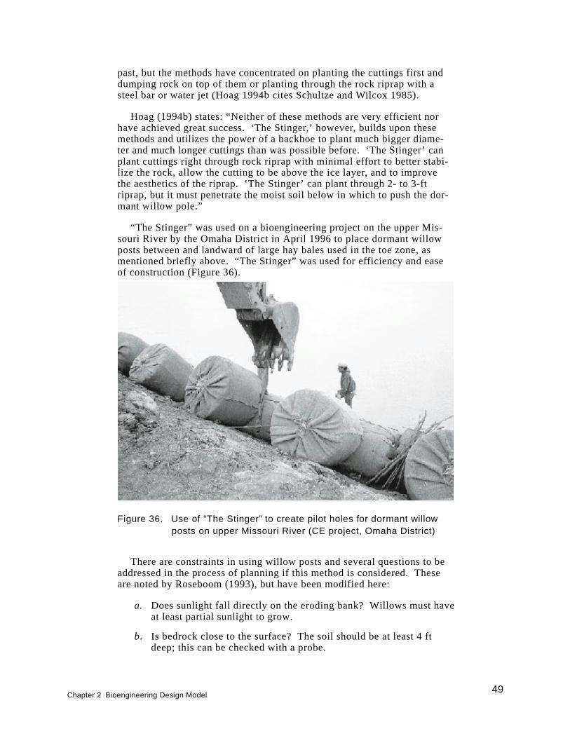
past, but the methods have concentrated on planting the cuttings first anddumping rock on top of them or planting through the rock riprap with asteel bar or water jet (Hoag 1994b cites Schultze and Wilcox 1985).
Hoag (1994b) states: “Neither of these methods are very efficient norhave achieved great success. ‘The Stinger,’ however, builds upon thesemethods and utilizes the power of a backhoe to plant much bigger diame-ter and much longer cuttings than was possible before. ‘The Stinger’ canplant cuttings right through rock riprap with minimal effort to better stabi-lize the rock, allow the cutting to be above the ice layer, and to improvethe aesthetics of the riprap. ‘The Stinger’ can plant through 2- to 3-ftriprap, but it must penetrate the moist soil below in which to push the dor-mant willow pole.”
“The Stinger” was used on a bioengineering project on the upper Mis-souri River by the Omaha District in April 1996 to place dormant willowposts between and landward of large hay bales used in the toe zone, asmentioned briefly above. “The Stinger” was used for efficiency and easeof construction (Figure 36).
There are constraints in using willow posts and several questions to beaddressed in the process of planning if this method is considered. Theseare noted by Roseboom (1993), but have been modified here:
a. Does sunlight fall directly on the eroding bank? Willows must haveat least partial sunlight to grow.
b. Is bedrock close to the surface? The soil should be at least 4 ftdeep; this can be checked with a probe.
Figure 36. Use of “The Stinger” to create pilot holes for dormant willowposts on upper Missouri River (CE project, Omaha District)
Chapter 2 Bioengineering Design Model49
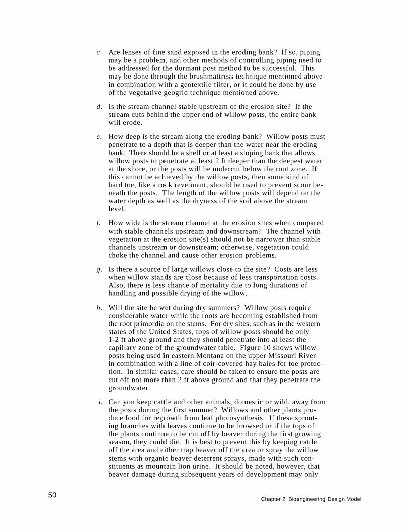
c. Are lenses of fine sand exposed in the eroding bank? If so, pipingmay be a problem, and other methods of controlling piping need tobe addressed for the dormant post method to be successful. Thismay be done through the brushmattress technique mentioned abovein combination with a geotextile filter, or it could be done by useof the vegetative geogrid technique mentioned above.
d. Is the stream channel stable upstream of the erosion site? If thestream cuts behind the upper end of willow posts, the entire bankwill erode.
e. How deep is the stream along the eroding bank? Willow posts mustpenetrate to a depth that is deeper than the water near the erodingbank. There should be a shelf or at least a sloping bank that allowswillow posts to penetrate at least 2 ft deeper than the deepest waterat the shore, or the posts will be undercut below the root zone. Ifthis cannot be achieved by the willow posts, then some kind ofhard toe, like a rock revetment, should be used to prevent scour be-neath the posts. The length of the willow posts will depend on thewater depth as well as the dryness of the soil above the streamlevel.
f. How wide is the stream channel at the erosion sites when comparedwith stable channels upstream and downstream? The channel withvegetation at the erosion site(s) should not be narrower than stablechannels upstream or downstream; otherwise, vegetation couldchoke the channel and cause other erosion problems.
g. Is there a source of large willows close to the site? Costs are lesswhen willow stands are close because of less transportation costs.Also, there is less chance of mortality due to long durations ofhandling and possible drying of the willow.
h. Will the site be wet during dry summers? Willow posts requireconsiderable water while the roots are becoming established fromthe root primordia on the stems. For dry sites, such as in the westernstates of the United States, tops of willow posts should be only1-2 ft above ground and they should penetrate into at least thecapillary zone of the groundwater table. Figure 10 shows willowposts being used in eastern Montana on the upper Missouri Riverin combination with a line of coir-covered hay bales for toe protec-tion. In similar cases, care should be taken to ensure the posts arecut off not more than 2 ft above ground and that they penetrate thegroundwater.
i. Can you keep cattle and other animals, domestic or wild, away fromthe posts during the first summer? Willows and other plants pro-duce food for regrowth from leaf photosynthesis. If these sprout-ing branches with leaves continue to be browsed or if the tops ofthe plants continue to be cut off by beaver during the first growingseason, they could die. It is best to prevent this by keeping cattleoff the area and either trap beaver off the area or spray the willowstems with organic beaver deterrent sprays, made with such con-stituents as mountain lion urine. It should be noted, however, thatbeaver damage during subsequent years of development may only
50Chapter 2 Bioengineering Design Model

promote resprouting of branches from the main stem and actuallypromote a shrubby-like plant. This is a positive effect from a sur-face roughness perspective, whereas the many branches slow thecurrent and promote sedimentation that can lead to other plantcolonization.
j . Have debris jams or trees and logs forced floodwater into theeroding bank? These must be removed at least to the point wherethey are not directing water into a bank. Trees and logs can bemoved parallel to the bank and cabled to dead men. Care shouldbe taken, however, to ensure the upstream end is not flanked bycurrents, thus possibly jeopardizing that bank reach.
The dormant post method using willow provides a low-cost bank stabili-zation method with both wildlife and fisheries benefits. Roseboom (1993)reported that the method has received widespread support by both the agri-cultural and environmental communities: Farm Bureau, Soil and WaterConservation Districts, American Fisheries Society, and The Nature Con-servancy. The willows hold the soil together long enough for other plantsto become established on the bank through succession. Together, theyprovide a natural system of food and cover. More can be found on thismethod in the case study provided in Report 2.
Dormant cuttings. Dormant cuttings, sometimes called “live stakes,”involve the insertion and tamping of live, rootable cuttings into the groundor sometimes geotextile substrate. In higher velocity streams, such as over5 fps, this method usually is applied in the splash zone with a combinationof other methods, such as the brushmattress and root wad methods. Dor-mant cuttings can be used as live stakes in the brushmattress and wattlingas opposed to or in combination with the wedge-shaped constructionstakes previously mentioned. They can also be placed adjacent to thebrushmattress. They can also be used in the matrix openings of the rootwad logs along with root pads of other vegetative materials. If cuttingsare used alone in the splash zone, the toe should be very stable and veloci-ties should be less than 5 fps. Also, the soil in which they are placedshould be fairly cohesive. Figure 37a-c shows an application of bankers(Salix X cotteti) and streamco (S. purpurea‘streamco’) willow cuttingsthat were installed on Irish Creek in North Carolina by the NRCS. Thesewillow were installed on a fairly cohesive bank on a straight reach with astable toe.
Dormant cuttings can vary in size, but are usually a minimum of 0.5 in.in diameter at the basal end (Hoag 1994b). Cuttings can be used that areup to 2 to 3 in. in diameter and have been noted by Hoag (1993) to havethe highest survival rates. Cutting length is largely determined by thedepth to the mid-summer water table and erosive force of the stream at theplanting site (Hoag 1993). Plantings can occur at the water line as in thesplash zone, up the bank into the bank zone, and on top of the bank (terracezone) in relatively dry soil, as long as cuttings are long enough to reachinto the mid-summer water table (Hoag 1993).
Cuttings should have their side branches cleanly removed and the barkintact so that the cutting is one single stem. Care should be taken to makeclean cuts at the top and the bottom so that the bark is not separated from
Chapter 2 Bioengineering Design Model51
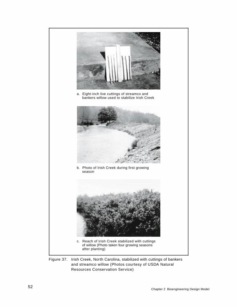
Figure 37. Irish Creek, North Carolina, stabilized with cuttings of bankersand streamco willow (Photos courtesy of USDA NaturalResources Conservation Service)
a. Eight-inch live cuttings of streamco andbankers willow used to stabilize Irish Creek
b. Photo of Irish Creek during first growingseason
c. Reach of Irish Creek stabilized with cuttingsof willow (Photo taken four growing seasonsafter planting)
52Chapter 2 Bioengineering Design Model
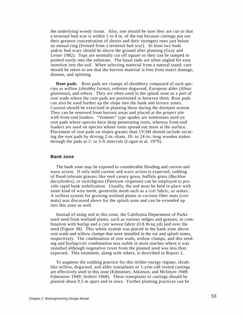
the underlying woody tissue. Also, one should be sure they are cut so thata terminal bud scar is within 1 to 4 in. of the top because cuttings put outtheir greatest concentration of shoots and their strongest ones just belowan annual ring (formed from a terminal bud scar). At least two budsand/or bud scars should be above the ground after planting (Gray andLeiser 1982). Tops are normally cut off square so they can be tamped orpushed easily into the substrate. The basal ends are often angled for easyinsertion into the soil. When selecting material from a natural stand, careshould be taken to see that the harvest material is free from insect damage,disease, and splitting.
Root pads. Root pads are clumps of shrubbery composed of such spe-cies as willow (shrubby forms), redosier dogwood, European alder (Alnusglutinosa), and others. They are often used in the splash zone as a part ofroot wads where the root pads are positioned in between them. Root padscan also be used further up the slope into the bank and terrace zones.Caution should be exercised in planting these during the dormant season.They can be removed from harvest areas and placed at the project sitewith front-end loaders. “Veimeer” type spades are sometimes used onroot pads where species have deep penetrating roots, whereas front-endloaders are used on species whose roots spread out more at the surface.Placement of root pads on slopes greater than 1V:6H should include secur-ing the root pads by driving 2-in.-diam, 18- to 24-in.-long wooden stakesthrough the pads at 2- to 3-ft intervals (Logan et al. 1979).
Bank zone
The bank zone may be exposed to considerable flooding and current andwave action. If only mild current and wave action is expected, soddingof flood-tolerant grasses like reed canary grass, buffalo grass (Buchloedactyloides), or switchgrass (Panicum virgatum) can be employed to pro-vide rapid bank stabilization. Usually, the sod must be held in place withsome kind of wire mesh, geotextile mesh such as a coir fabric, or stakes.A soilless system for growing wetland plants in coconut fiber mats (coirmats) was discussed above for the splash zone and can be extended upinto this zone as well.
Instead of using sod in this zone, the California Department of Parksused seed from wetland plants, such as various sedges and grasses, in com-bination with burlap and a coir woven fabric (0.8 lb/sq yd) laid over theseed (Figure 38). This whole system was placed in the bank zone aboveroot wads and willow clumps that were installed in the toe and splash zones,respectively. The combination of root wads, willow clumps, and this seed-ing and burlap/coir combination was stable in most reaches where it wasinstalled although vegetative cover from the planted seed was less thanexpected. This treatment, along with others, is described in Report 2.
To augment the sodding practice for this milder energy regime, shrub-like willow, dogwood, and alder transplants or 1-year-old rooted cuttingsare effectively used in this zone (Edminster, Atkinson, and McIntyre 1949;Edminster 1949; Seibert 1968). These transplants or cuttings should beplanted about 0.5 m apart and in rows. Further planting practices can be
Chapter 2 Bioengineering Design Model53
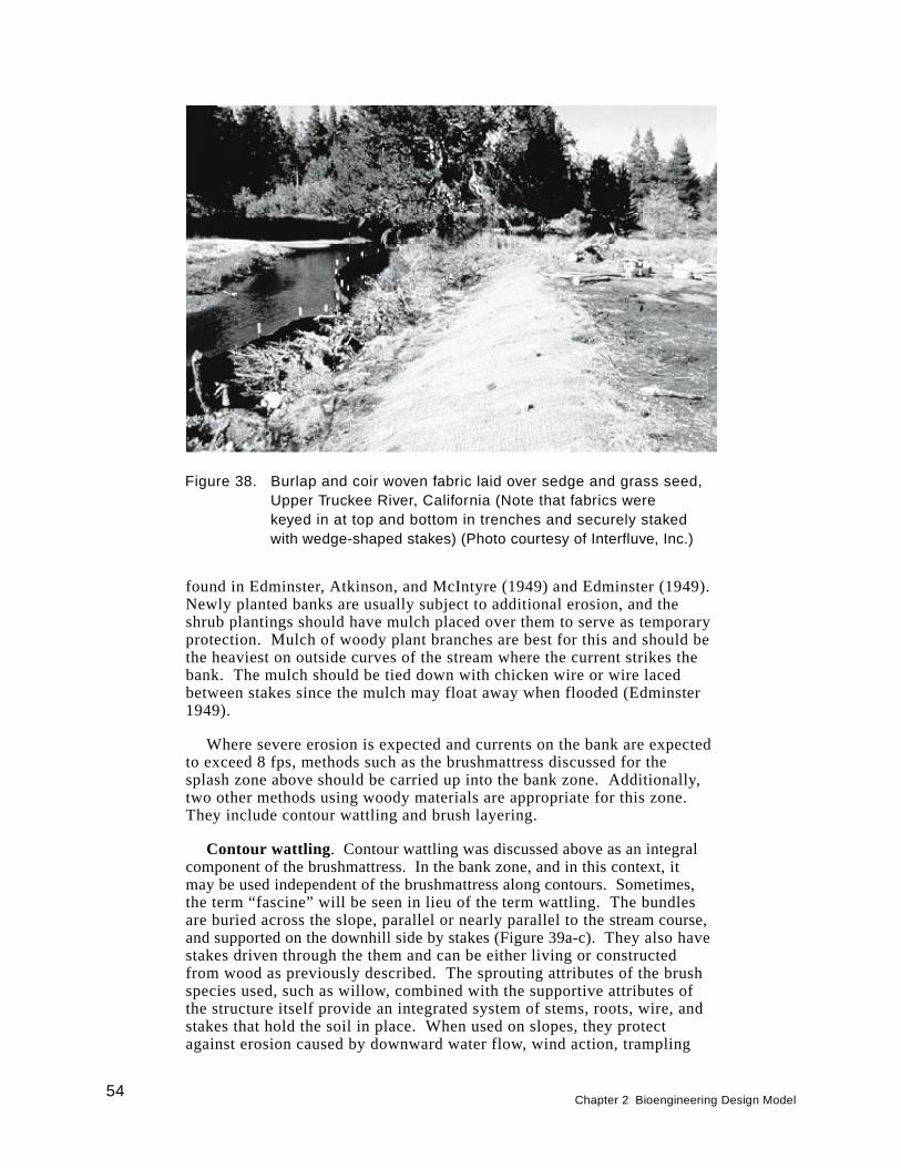
found in Edminster, Atkinson, and McIntyre (1949) and Edminster (1949).Newly planted banks are usually subject to additional erosion, and theshrub plantings should have mulch placed over them to serve as temporaryprotection. Mulch of woody plant branches are best for this and should bethe heaviest on outside curves of the stream where the current strikes thebank. The mulch should be tied down with chicken wire or wire lacedbetween stakes since the mulch may float away when flooded (Edminster1949).
Where severe erosion is expected and currents on the bank are expectedto exceed 8 fps, methods such as the brushmattress discussed for thesplash zone above should be carried up into the bank zone. Additionally,two other methods using woody materials are appropriate for this zone.They include contour wattling and brush layering.
Contour wattling . Contour wattling was discussed above as an integralcomponent of the brushmattress. In the bank zone, and in this context, itmay be used independent of the brushmattress along contours. Sometimes,the term “fascine” will be seen in lieu of the term wattling. The bundlesare buried across the slope, parallel or nearly parallel to the stream course,and supported on the downhill side by stakes (Figure 39a-c). They also havestakes driven through the them and can be either living or constructedfrom wood as previously described. The sprouting attributes of the brushspecies used, such as willow, combined with the supportive attributes ofthe structure itself provide an integrated system of stems, roots, wire, andstakes that hold the soil in place. When used on slopes, they protectagainst erosion caused by downward water flow, wind action, trampling
Figure 38. Burlap and coir woven fabric laid over sedge and grass seed,Upper Truckee River, California (Note that fabrics werekeyed in at top and bottom in trenches and securely stakedwith wedge-shaped stakes) (Photo courtesy of Interfluve, Inc.)
54Chapter 2 Bioengineering Design Model
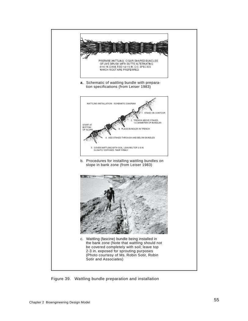
Figure 39. Wattling bundle preparation and installation
a. Schematic of wattling bundle with prepara-tion specifications (from Leiser 1983)
b. Procedures for installing wattling bundles onslope in bank zone (from Leiser 1983)
c. Wattling (fascine) bundle being installed inthe bank zone (Note that wattling should notbe covered completely with soil; leave top2-3 in. exposed for sprouting purposes(Photo courtesy of Ms. Robin Sotir, RobinSotir and Associates)
Chapter 2 Bioengineering Design Model55
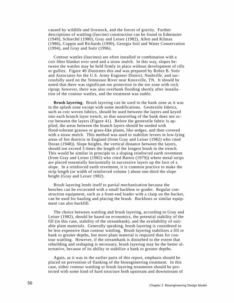
caused by wildlife and livestock, and the forces of gravity. Furtherdescriptions of wattling (fascine) construction can be found in Edminster(1949), Schiechtl (1980), Gray and Leiser (1982), Allen and Klimas(1986), Coppin and Richards (1990), Georgia Soil and Water Conservation(1994), and Gray and Sotir (1996).
Contour wattles (fascines) are often installed in combination with acoir fiber blanket over seed and a straw mulch. In this way, slopes be-tween the wattles may be held firmly in place without development of rillsor gullies. Figure 40 illustrates this and was prepared by Robin B. Sotirand Associates for the U.S. Army Engineer District, Nashville, and suc-cessfully used on the Tennessee River near Knoxville, TN. It should benoted that there was significant toe protection in the toe zone with rockriprap; however, there was also overbank flooding shortly after installa-tion of the contour wattles, and the treatment was stable.
Brush layering. Brush layering can be used in the bank zone as it wasin the splash zone except with some modifications. Geotextile fabrics,such as coir woven fabrics, should be used between the layers and keyedinto each branch layer trench, so that unraveling of the bank does not oc-cur between the layers (Figure 41). Before the geotextile fabric is ap-plied, the areas between the branch layers should be seeded withflood-tolerant grasses or grass-like plants, like sedges, and then coveredwith a straw mulch. This method was used to stabilize levees in low-lyingareas of fen districts in England (from Gray and Leiser (1982) who citedDoran (1948)). Slope heights, the vertical distance between the layers,should not exceed 3 times the length of the longest brush in the trench.This would be similar in principle to a sloping reinforced earth revetment(from Gray and Leiser (1982) who cited Bartos (1979)) where metal stripsare placed essentially horizontally in successive layers up the face of aslope. In a reinforced earth revetment, it is common practice to make thestrip length (or width of reinforced volume ) about one-third the slopeheight (Gray and Leiser 1982).
Brush layering lends itself to partial mechanization because thebenches can be excavated with a small backhoe or grader. Regular con-struction equipment, such as a front-end loader with a clasp on the bucket,can be used for hauling and placing the brush. Backhoes or similar equip-ment can also backfill.
The choice between wattling and brush layering, according to Gray andLeiser (1982), should be based on economics, the potential stability of thefill (in this case, stability of the streambank), and the availability of suit-able plant materials. Generally speaking, brush layering is considered tobe less expensive than contour wattling. Brush layering stabilizes a fill orbank to greater depths, but more plant material is required than for con-tour wattling. However, if the streambank is disturbed to the extent thatrebuilding and reshaping is necessary, brush layering may be the better al-ternative, because of its ability to stabilize a bank to greater depths.
Again, as it was in the earlier parts of this report, emphasis should beplaced on prevention of flanking of the bioengineering treatment. In thiscase, either contour wattling or brush layering treatments should be pro-tected with some kind of hard structure both upstream and downstream of
56Chapter 2 Bioengineering Design Model
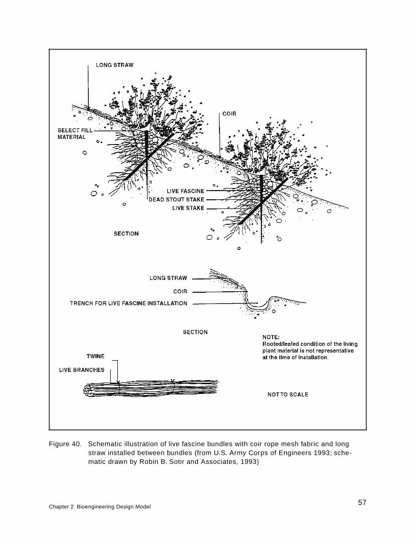
Figure 40. Schematic illustration of live fascine bundles with coir rope mesh fabric and longstraw installed between bundles (from U.S. Army Corps of Engineers 1993; sche-matic drawn by Robin B. Sotir and Associates, 1993)
Chapter 2 Bioengineering Design Model57
the treatment. If natural hard points, such as large boulders, rock outcrop-pings, or hard geological strata, are not present, then one should consideruse of a rock refusal. This would be rock riprap that starts at the bottomof the bank, continues up the bank, and is keyed into the bank (Figure 4).
Terrace zone
The terrace zone, as mentioned earlier, is rarely flooded and usually notsubjected to erosive action of the stream except during occasional flooding.When flooded, it receives overbank flooding with return flows that cancause gullying and rilling to occur on the fall of the hydrograph. It is inthis zone that vegetation is needed with deeply penetrating roots to holdthe bank together, such as larger flood-tolerant trees. Grasses, otherherbs, and shrubs can be planted in between the trees, depending on theirshade tolerance. Bioengineering, per se, is not normally used in this zoneunless there are deep gullies that have occurred as a result of return flowsor slopes still occur in this zone that are 3H:1V or greater. In these cases,branch layering or contour wattling treatments are often employed acrossthe gully or on the contours of the slope.
Care should be taken in using large trees in this zone. They should beplanted far enough back from the bank that their shade does not kill outthe vegetation in the splash and bank zones. Narrow channels, especially,can be completely shaded from one side. When trees are planted in thiszone, they are planted either as container-grown (potted) or bare-rootplants. Suggestions vary on the size of container-grown plants. Leiser
Figure 41. Brush layering with coir woven fabric and long straw underfabric (Coir fabric and straw help control rillying and gullyingbetween layers) (adapted from Gray and Leiser 1982)
58Chapter 2 Bioengineering Design Model
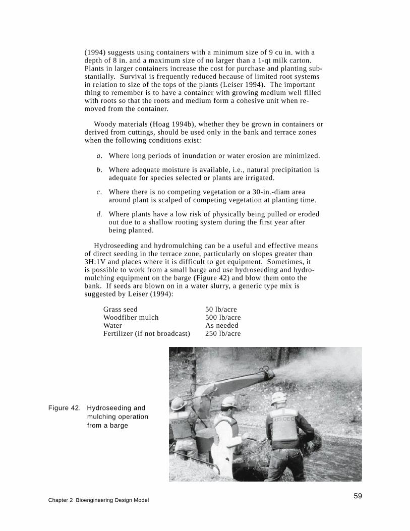
(1994) suggests using containers with a minimum size of 9 cu in. with adepth of 8 in. and a maximum size of no larger than a 1-qt milk carton.Plants in larger containers increase the cost for purchase and planting sub-stantially. Survival is frequently reduced because of limited root systemsin relation to size of the tops of the plants (Leiser 1994). The importantthing to remember is to have a container with growing medium well filledwith roots so that the roots and medium form a cohesive unit when re-moved from the container.
Woody materials (Hoag 1994b), whether they be grown in containers orderived from cuttings, should be used only in the bank and terrace zoneswhen the following conditions exist:
a. Where long periods of inundation or water erosion are minimized.
b. Where adequate moisture is available, i.e., natural precipitation isadequate for species selected or plants are irrigated.
c. Where there is no competing vegetation or a 30-in.-diam areaaround plant is scalped of competing vegetation at planting time.
d. Where plants have a low risk of physically being pulled or erodedout due to a shallow rooting system during the first year afterbeing planted.
Hydroseeding and hydromulching can be a useful and effective meansof direct seeding in the terrace zone, particularly on slopes greater than3H:1V and places where it is difficult to get equipment. Sometimes, itis possible to work from a small barge and use hydroseeding and hydro-mulching equipment on the barge (Figure 42) and blow them onto thebank. If seeds are blown on in a water slurry, a generic type mix issuggested by Leiser (1994):
Grass seed 50 lb/acreWoodfiber mulch 500 lb/acreWater As neededFertilizer (if not broadcast) 250 lb/acre
Figure 42. Hydroseeding andmulching operationfrom a barge
Chapter 2 Bioengineering Design Model59
According to Leiser (1994), the slurry should be continuously mixed asingredients are added and mixed at least 5 min following the addition ofthe last ingredients before application begins. The slurry should be con-tinuously mixed until used, and application must be completed within 2 hrof the last addition. Water should be potable or at least filtered so as notto clog spraying equipment. The slurry should be applied at a rate that isnonerosive and minimizes runoff.
On level areas and slopes of less than 3H:1V, seed should be broadcastby mechanical hand or power-operated spreaders or drilled on contourwith a Brillion or range drill as site conditions permit. Broadcasted seedshould be covered by raking or dragging with a chain, chainlink fence, orother approved means unless previously planted with cuttings or trans-plants (Leiser 1994).
Sometimes surface drainage water intercepts the terrace zone from in-land areas and can cause gullying not only in the terrace zone, but in theother zones on the bank. This water should be diverted or controlled witha small furrow or trench at the top of the bank. This trench should be sod-ded to prevent erosion.
Velocities for Design Purposes
The purpose of this section is to provide some velocity informationthat bioengineering systems have been noted to sustain so that plannersand designers have a basis for choosing bioengineering systems and theparticular kind of system. Some of the velocity information was derivedfrom the literature while other information was measured at local pointsat case study locations where bioengineering treatments were installed.Velocities vary so much within a stream that local velocities near thetreated section are the most valuable. Admittedly, the measured velocitiesare much lower than considered maximum threshold values that could besustained by the installed structures. This is because when measurementswere made, they were made with current meters in the local vicinity of thebioengineering treatment on the fall of the hydrograph when water levelsand currents during flood events were not a safety hazard. Remote currentmeters exist, but would have been silted in or damaged by debris flowduring these flood events.
Most of the velocity information in the literature concerns itself withturf grass cover that was designed for erosion control ditches or water-ways. Little information exists on combinations of systems, i.e., bioengi-neering treatments, containing both herbaceous and woody species.Engineer Manual (EM) 1110-2-1205 (U.S. Army Corps of Engineers1989) states that herbaceous or woody vegetation may be used to protectchannel side slope areas (depending on the frequency of inundation, veloc-ity, and geotechnical constraints to infrequent flooding) and other bank ar-eas where velocities are not expected to exceed 6 to 8 fps. Informationconcerning influence of vegetation (bermuda grass) or variation of veloc-ity with depth below water surface is shown in Henderson and Shields(1984) who cites Parsons (1963).
60Chapter 2 Bioengineering Design Model
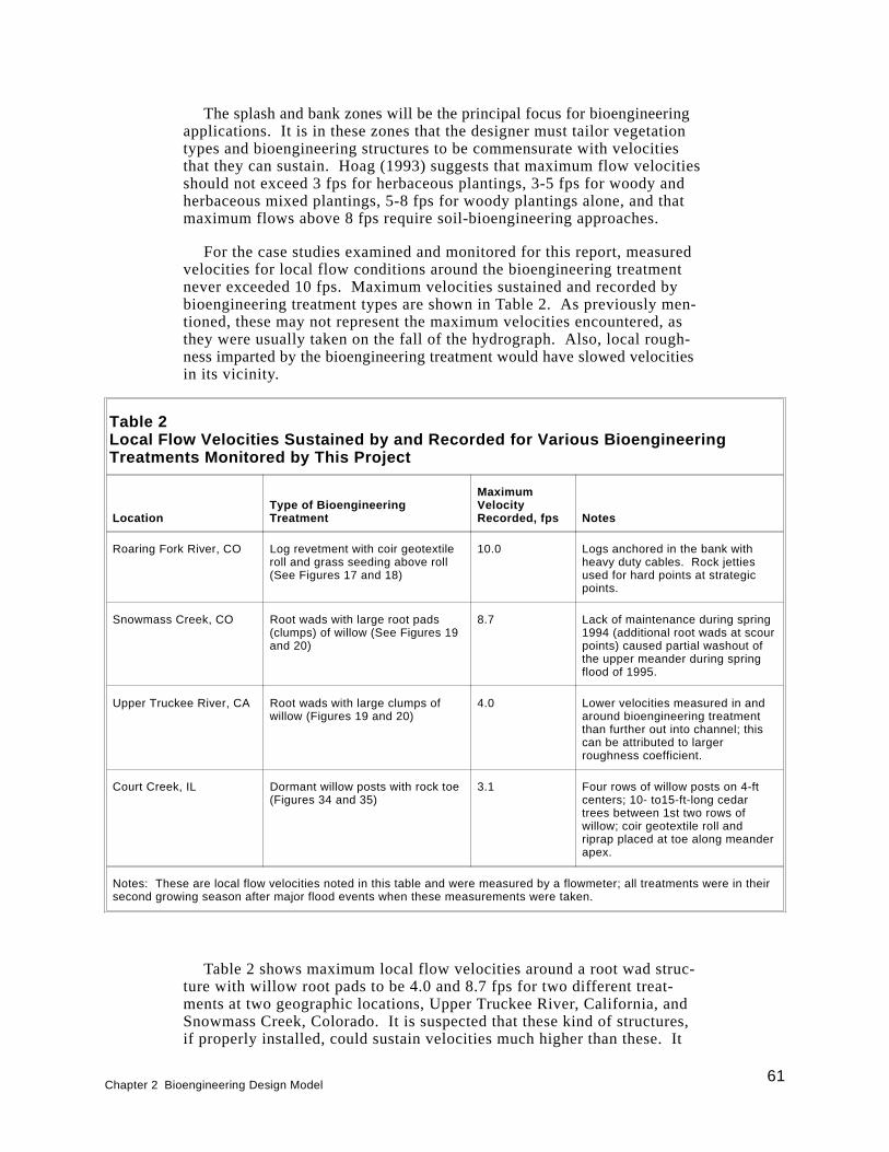
The splash and bank zones will be the principal focus for bioengineeringapplications. It is in these zones that the designer must tailor vegetationtypes and bioengineering structures to be commensurate with velocitiesthat they can sustain. Hoag (1993) suggests that maximum flow velocitiesshould not exceed 3 fps for herbaceous plantings, 3-5 fps for woody andherbaceous mixed plantings, 5-8 fps for woody plantings alone, and thatmaximum flows above 8 fps require soil-bioengineering approaches.
For the case studies examined and monitored for this report, measuredvelocities for local flow conditions around the bioengineering treatmentnever exceeded 10 fps. Maximum velocities sustained and recorded bybioengineering treatment types are shown in Table 2. As previously men-tioned, these may not represent the maximum velocities encountered, asthey were usually taken on the fall of the hydrograph. Also, local rough-ness imparted by the bioengineering treatment would have slowed velocitiesin its vicinity.
Table 2 shows maximum local flow velocities around a root wad struc-ture with willow root pads to be 4.0 and 8.7 fps for two different treat-ments at two geographic locations, Upper Truckee River, California, andSnowmass Creek, Colorado. It is suspected that these kind of structures,if properly installed, could sustain velocities much higher than these. It
Table 2Local Flow Velocities Sustained by and Recorded for Various BioengineeringTreatments Monitored by This Project
LocationType of BioengineeringTreatment
MaximumVelocityRecorded, fps Notes
Roaring Fork River, CO Log revetment with coir geotextileroll and grass seeding above roll(See Figures 17 and 18)
10.0 Logs anchored in the bank withheavy duty cables. Rock jettiesused for hard points at strategicpoints.
Snowmass Creek, CO Root wads with large root pads(clumps) of willow (See Figures 19and 20)
8.7 Lack of maintenance during spring1994 (additional root wads at scourpoints) caused partial washout ofthe upper meander during springflood of 1995.
Upper Truckee River, CA Root wads with large clumps ofwillow (Figures 19 and 20)
4.0 Lower velocities measured in andaround bioengineering treatmentthan further out into channel; thiscan be attributed to largerroughness coefficient.
Court Creek, IL Dormant willow posts with rock toe(Figures 34 and 35)
3.1 Four rows of willow posts on 4-ftcenters; 10- to15-ft-long cedartrees between 1st two rows ofwillow; coir geotextile roll andriprap placed at toe along meanderapex.
Notes: These are local flow velocities noted in this table and were measured by a flowmeter; all treatments were in theirsecond growing season after major flood events when these measurements were taken.
Chapter 2 Bioengineering Design Model61
was noted earlier in this report that D. Rosgen1 measured local flow ve-locities around root wads on the Blanco River, Colorado, to be 12.0 fps.
Some of the treatments noted in Table 2 had some partial failures eventhough at least half of the reaches where these were installed remained in-tact and the treatments continued to function. The treatment containingthe log revetment with coir geotextile roll on the Roaring Fork River,Colorado, experienced some failure. The lower half of the reach in whichit was installed washed out after a major flood in the spring of 1995. Thiswas due to the problem of insufficiently burying and keying in the bottom-most log of the revetment into the streambed. Consequently, scour under-mined the structure, and it failed along the lower half of the reach.
The root wad structure on Snowmass Creek, Colorado, had a partialfailure. After the spring runoff in 1994, the sponsor noticed minor dam-age around certain critical points that needed maintenance, the addition ofmore root wad logs. The contractor instead placed rock at inappropriateplaces. Consequently, the creek flooded during the spring runoff of 1995,and the outside of the lower section of the upper meander washed out anderoded about 6 ft of bank. In these two cases, it points to the need for prop-erly keying in structures for toe and end protection and to monitoring andpossible maintenance early in the life of a bioengineering project. Earlymonitoring and maintenance can actually prevent these failures and othermore severe impacts caused by the failures. For example, if the root wadsin the Snowmass Creek example above were dislocated, they could causemore severe erosion than normal erosion without the bank treatment. Thisearly monitoring and maintenance should be included in the constructioncontract at the outset.
62Chapter 2 Bioengineering Design Model
1Personal Communication, July 1996, Dave Rosgen, President, Wildland Hydrology,
Pagosa Springs, CO.
3 Plant Acquisition, Handling,and Timing of Planting
Almost all of the plants used in bioengineering can be considered wet-land plants, either obligative or facultative. Some of the exceptions wouldoccur in the terrace zone that is infrequently flooded; however, all mustbe somewhat flood tolerant. Both herbaceous and woody plants are used.Herbaceous plants may be emergent aquatic plants like rushes and sedgesor grasses and other forbs that require nonaquatic but moist conditions atleast part of the year. The herbaceous plants are usually acquired as vege-tative material such as sprigs, rhizomes, and tubers. Sometimes seed isacquired, but is used when the threat of flooding is low in the bank andterrace zones. Otherwise, they would wash out quite easily unless theyare seeded underneath or in a geotextile mat or fabric that is securelyanchored.
Woody plants used for bioengineering purposes usually consist of stemcuttings, those that quickly sprout roots and stems from the parent stem.These are plants such as willow, some dogwood, and some alder. Theycan be supplemented by bare-root or containerized stock, particularly inthe bank or terrace zones where they are not subjected to frequent flood-ing. Gray and Sotir (1996) list several such plants that can be used in bio-engineering and relate their flood tolerances, along with some othercharacteristics.
There are three suitable methods to acquire plants for bioengineeringtreatments. Each has, according to Pierce (1994), noteworthy advantages,but critical disadvantages that make plant acquisition and handling an im-portant and complex process. The three methods are to: (a) purchaseplants, (b) collect plants from the wild; and (c) propagate and grow plants.
Regardless of the method chosen, it is necessary to conduct the follow-ing steps (Pierce 1994):
a. The available hydrologic regime and soil types should be deter-mined. General positioning of the plant type, e.g., emergentaquatic, shrubby willow, should be in accordance with the plantzone (splash, bank, and terrace) defined in Chapter 2.
b. A list of common wetland plant species in the region and morepreferably in the watershed containing the stream of concern
Chapter 3 Plant Acquisition, Handling, and Timing of Planting63

should be prepared, and these should be matched to the hydrologyand substrate of the target streambank reach to be addressed.
c. Species should be selected that will match the energy of the envi-ronment and the hydraulic conveyance constraints that may be im-posed by the situation. For instance, one must be careful to uselow-lying and flexible vegetation that lays down with water flows ifhydraulic conveyance must be maximized. In such cases, use flood-tolerant grasses or grass-like plants and shrubby woody species.
d. Species should be selected that will not be dug out or severelygrazed by animals, especially muskrat (Ondatia zibethieus), nutria(Myocastor coypes), beaver, Canada geese, and carp (Cyprinuscarpio). Other animals may influence plant growth and survival.If plants chosen are unavoidably vulnerable to animal damage,then plant protection measures must be used, such as fencing,wire, or nylon cages around them or use of repellents.
e. Additional special requirements and constraints of the site shouldbe determined. For instance, some sites may be prone to sedimentdeposition or have a bank geometry that is almost vertical. In suchcases, it may be difficult to obtain success with emergent aquaticplants that may become covered with sediment and suffocate orwhich have water too deep in which to grow unless the bank isreshaped. The former situation may necessitate the use of willowthat can be planted as cuttings or posts and be less susceptible tocomplete coverage by sediment.
f. A suite of species that would be suitable should be prepared. Thismay be limited to those currently available from commercialsources if there is no possibility to collect in the wild or haveplants contract grown.
Pierce (1994) also gives a number of steps and advantages and disad-vantages of the three methods of acquiring plants, and these have beenadapted with some modifications below. Each project will have uniquesituations, but the following will serve as a guide.
Purchasing Plants
The steps for purchasing plants are as follows:
a. A list of wetland plant suppliers should be acquired, such as“Directory of Plant Vendors,” (USDA Soil Conservation Service1992). Vendors’ catalogs and plant availability lists should berequested.
b. The condition in which the plants from each supplier are to bedelivered should be determined—potted, bare root, rhizomes and tu-bers, or seed. This is important because if the plants are to be used inthe splash zone where they may be partially covered with water, seedof emergent aquatic plants will not germinate underwater.
64Chapter 3 Plant Acquisition, Handling, and Timing of Planting

c. The plant list should be matched against species availability, andone should not assume that all species advertised will be availablein needed quantities.
d. Samples should be ordered, if available, and plant condition andidentification verified.
e. A flexible delivery schedule should be negotiated allowing forunpredicted delays in planting.
f. Some suppliers may grow plants on contract, but it will be necessaryto contact them several months to a year before the plants areneeded.
Advantages
The advantages of purchasing plants are as follows:
a. Plants are readily available at the planting location in predictedquantities and at the required time.
b. No special expertise is required to collect or grow the plants.
c. No wild source for the plants must be found, and there are no har-vesting permits to obtain from State or local governments.
d. Cost can be more readily predicted and controllable than harvestingfrom the wild or growing one’s own.
Disadvantages
The disadvantages of purchasing plants are as follows:
a. Plants may arrive in poor condition.
b. Selection of species is limited.
c. Plants may not be adapted to the local environment. Contractgrowing may solve this problem.
d. Cost may be high and shipping cost needs to be considered.
e. Quantities may be limited.
f. It may be necessary to store large quantities of plants and conse-quently necessitate procurement of adequate and appropriatestorage facilities.
Chapter 3 Plant Acquisition, Handling, and Timing of Planting65
Collecting Plants From the Wild
Collecting plants from the wild may be very demanding because ofhard-to-reach plants that are off main access routes. Wild plants mustthen be moved immediately to a nursery or holdover site or to the projectsite. Logistical and plant handling problems need to be carefully assessedand solutions planned well ahead of time. Care should be taken if thismethod is selected because of the possibility of contaminating the har-vested donor plants with unwanted weedy species that could become aproblem at the project site. Samples should be collected ahead of time inorder to determine what kind of problems will be encountered in collect-ing, transporting, and storing each species. Caution should be exercisedin collecting plants from harvesting areas so that the plant community isnot extirpated, left functional, and the ecosystem not damaged. This canbe done by not harvesting in one spot, but dispersing the harvest areas.Care should be taken by harvesting only fairly common plants. Certainly,rare plants should be avoided.
Advantages
The advantages of collecting plants from the wild are as follows:
a. Plants are likely to be ecotypically adapted to the local environment.
b. Plants can often be collected at a low cost.
c. Plants can be collected as needed and will not require extendedstorage.
d. Availability of species is very flexible and can be adjusted as theneed arises.
e. No special expertise is required to grow the plants.
f. A very wide diversity of plants is available.
Disadvantages
The disadvantages of collecting plants from the wild are as follows:
a. Weedy species may contaminate the source area and be inadver-tantly transplanted.
b. A suitable area must be found, and more than one donor area mayneed to be located.
c. Plants may not be in an appropriate condition for planting. For in-stance, they may be highly stressed, diseased, or insect infested.
d. Species must be accurately identified, or rare plants or weeds maybe harvested by mistake.
66Chapter 3 Plant Acquisition, Handling, and Timing of Planting
e. Cost of collection and logistics may be very high.
f. Outdoor hazards such as snakes, adverse weather, noxious plants,e.g., poison ivy and stinging nettles, parasites, and other inhibitingitems may interfere with collection efforts.
g. It is often necessary to procure a permit for collecting from nativeplant sources and wetlands, in particular.
Growing Plants
Plants to be grown for planting can be grown in a greenhouse or otherenclosed facility or, in the case of emergent aquatics, outdoor ponds ortroughs containing water. In either case, the plants must first be acquiredfrom the wild or other growers and propagated. If seeds are used forpropagation, they must first be stratified (subjected to various treatmentssuch as soaking and temperature differences), but germination require-ments for most wetland plant seeds are unknown. If a greenhouse is to beused, a number of limitations and constraints must be overcome, such asroom for pots, adequate ventilation, and requirements or problems associ-ated with fertilizing, watering, and disease and pest control.
Plants can be grown in coir carpets (Figure 25a-c), mats, or rolls, to fa-cilitate early establishment, ease of transport, and rapid development.Emergent aquatic plants, especially, may be hydroponically grown in thegreenhouse or in outside troughs. Then, they can be transported to theplanting site ready to grow with roots already established in the carpet,mat, or roll. The U.S. Army Engineer Waterways Experiment Station(WES) used a coir carpet for this purpose in 1983 for growing and trans-porting ready-to-grow plants to a site in Mobile Bay for erosion control ofdredged material. This same concept can be used along streambanks andcan be used to an advantage when one is in an area with short growing sea-sons or where rapid installation is mandatory.
Advantages
The advantages of growing plants are as follows:
a. All of the advantages of purchasing plants can be realized.
b. The variety of species available can be as diverse as for plants col-lected in the wild, and plants can be planted in large quantities.
c. Plants can be available earlier in the season than purchased or col-lected plants.
d. Low cost is one of the primary reasons to grow stock for planting.
Chapter 3 Plant Acquisition, Handling, and Timing of Planting67
Disadvantages
The disadvantages of growing plants are as follows:
a. Space and facilities must be dedicated to growing plants.
b. Personnel with time and expertise to grow the plants may not beavailable.
c. There is an up-front investment in both fixed and variable overheaditems in order to establish a growing facility, and it may not be jus-tified unless there is a large and continuing need for planting stock.
Handling of Plant Materials
Plants need to be handled carefully to ensure their survival between thephases of acquisition (purchasing, growing, or harvesting from the wild)and transplanting because they will undergo transportation and plantingshock. Many problems associated with poor plant survival occur from thehandling of the plants between the nursery or collection site and the pro-ject planting site. Generally, the plant material needs to be kept cool,moist, and shaded (Hoag 1994b). They must be treated as living material;if the living attributes are lost, then the project is much more prone to faileven though dead plant materials in a bioengineering treatment can offersome erosion control through their physical attributes, e.g., acting as bankarmor, runoff retention through checkdam effects, current and wave deflec-tors. Plants are most easily collected when dormant. When plants are dor-mant, there is substantially more forgiveness in how they are handled.
Woody plants
Woody plants, particularly cuttings, should be collected when dormant;their survival decreases a lot if they are harvested and planted in a nondor-mant state. With bareroot or unrooted cuttings, keep them cool, moist,and in the dark until they are ready to be planted (Hoag 1994b). They canbe stored in a large cooler at 24-32 °F until just before planting. Cuttingscan be stored in this manner for several months (Platts et al. 1987). Thecuttings can be kept in a cooler, root cellar, garage, shop floor, or anyplace that is dark, moist, and cool at all times (Hoag 1994b). Often, cut-tings are placed on burlap and covered with sawdust or peat moss and thencovered with burlap after being moistened.
Hoag (1994b) advocates soaking of cuttings for a minimum of 24 hr,whether they are coming out of storage or directly after harvesting in thelate winter to early spring (Hoag, Young, and Gibbs 1991a,b; Hoag 1992).Some research recommends soaking the cuttings for as much as 10-14 days(Briggs and Munda 1992; Fenchel, Oaks, and Swenson 1988). The maincriterion is that the cuttings need to be removed from the water prior to rootemergence from the bark. This normally takes 7 to 9 days (Peterson and
68Chapter 3 Plant Acquisition, Handling, and Timing of Planting
Phipps 1976). Soaking is important because it initiates the root growthprocess within the inner layer of bark in willows and poplars (Hoag 1994b).
When woody plants are moved from the nursery, holding, or harvestingarea, to the project site, they should continue to receive careful handlingby keeping them moist and free from wind dessication. The latter can beachieved by ensuring they are covered with a light-colored (to reflectheat) and moist tarp. In the case of cuttings, they can be moved to the pro-ject site by moving them in barrels with water in them or some similarmethod. Actual planting of the plants shall follow the digging of holes assoon as possible, preferably no longer than 2-3 min, so that the excavatedsoil does not dry out. Use only the moist, excavated soil for backfill ofthe planting hole. Backfill should be tamped firmly to eliminate all voidsand to obtain close contact between the root systems and the native soils.When using containerized or balled and burlap stock, excess soil shouldbe smoothed and firmed around the plants leaving a slight depression tocollect rainfall. Plants should be placed 1 to 2 in. lower than they weregrown in the nursery to provide a soil cover over the root system (Leiser1994).
Herbaceous plants
Plant handling requirements of herbaceous plants are even more rigor-ous than woody plants as a general rule because they are usually obtainedin the spring when nurseries have them ready to ship or when they arereadily identified in the wild for collection. At those times, they are verysusceptible to dessication mortality. Consequently, they must be kept in amoist, shaded condition, or even better, in water-filled containers from thetime of collection from the wild or receipt from the nursery to the time oftransplanting. If herbaceous plants are identified and tagged for collectionin the spring or summer, they can be collected when dormant in the latefall or winter. During those times, they can be handled more freely, butshould still be prevented from drying out. When transporting from thenursery, holding, or harvesting area to the project site, this should be in acovered vehicle. If the weather is very hot, cooling from ice or refrigera-tion may be necessary. Exposure to high winds should be avoided. Plantscan be placed in a water-filled ditch or covered with soil in a shaded areafor storage of several days while awaiting planting. It is best not to storeplants longer than necessary, and delivery should be scheduled to matchplanting dates.
If herbaceous plants are to be grown, they will need to be grown fromseed or from collected rhizomes, tubers, or rooted stems or rootstock fromthe wild. Most wetland plant seed needs to be stratified and will not ger-minate underwater even after stratification. An experienced wetlands nurs-ery person should be consulted before attempting to grow wetland plantsfrom seed. Often, a cold treatment underwater is necessary for stratifica-tion (Pierce 1994). There are various other stratification methods of wet-land plants, such as hot and cold temperature treatments and treatmentswith various fertilizers. Rhizomes, tubers, and rooted stems and rootstockof wetland herbaceous plants can be grown out in wet troughs or ditchesand ponds containing fertilized sand and peat moss. Only enough water is
Chapter 3 Plant Acquisition, Handling, and Timing of Planting69
necessary to keep the rhizomes, tubers, etc., from drying out. Plants canbe grown out in the greenhouse over colder months, but will require hard-ening before transfer to the project site.
Hoag (1994b) stated that hardening off can be accomplished by removingthe plants from the greenhouse and placing them in a cool, partially shadedarea for 1-2 weeks. This is generally a lathe or slat house. Some are con-structed with snow fencing, which has wooden slats woven together withwire. According to Hoag (1994b), this type of structure allows a smallamount of direct sunlight and solar radiation through the slats to the plants,but not enough to burn them. A partially shaded spot near the plantingsite will also work. It is important to keep the plants well watered andmisted during the hardening off period.
Timing of Planting
Woody plants
Woody cuttings and transplants should always be planted in the dor-mant season for best chance of survival and growth. If they cannot beplanted in the dormant season, they should be held in cold storage, around28 °F, until they can be planted. Refrigerated trucks or vans are oftenused for this. Sometimes, storage lockers can be found and rented to keepmaterials dormant. Woody plants can be considered dormant when theirbuds are set in the fall, usually after the first hard freeze, until late winterto early spring when buds are noticed to swell.
Whether to plant in the fall or late winter-early spring will depend uponthe hydrology of the stream system in which one is working and the cli-matic conditions. If water levels are expected to be down in the fall andwinter and if plants can obtain growth in the early spring prior to floodevents, then planting at that time may make sense. Conversely, if waterlevels may fluctuate dramatically during the dormant season with accom-panying high velocities, then it may make sense to plant in the late springafter the threat of flood events. In any case, it is best to choose a plantingperiod where water levels are apt to be at normal flow levels or near nor-mal flow levels, if possible.
According to Leiser (1994), fall plantings may be preferred in areaswith late growing seasons, winter rains, and summer drought. This allowsa longer period of establishment before late spring when flooding ordrought occurs. However, bare-root plants may not be available until latefall or even mid-winter. Late fall plantings may not be desirable wherelate fall droughts occur, or where frost heaving is severe before new rootgrowth occurs. Spring planting dates are usually required for bare-rootstock, where sites are subject to late fall and winter frost heaving problems,or where flooding occurs in late fall to early spring. Spring plantingshould be scheduled as early as site conditions permit. Summer plantingsshould be avoided.
70Chapter 3 Plant Acquisition, Handling, and Timing of Planting

Herbaceous plants
Herbaceous pants, such as emergent aquatic plants, can be planted dur-ing both dormant and nondormant times of the year. However, if they areplanted in the nondormant season, they should be planted as early in thespring as possible to capitalize on maximum growth during the growingseason. Plantings during hot, summer months should be avoided becauseof the risk of drying plant stock and associated planting shock and possi-ble mortality. If planted during the dormant season, attention should stillbe given to the risk of flooding and current velocities that may wash theplants away before they have a chance to establish their roots in the sub-strate.
Chapter 3 Plant Acquisition, Handling, and Timing of Planting71
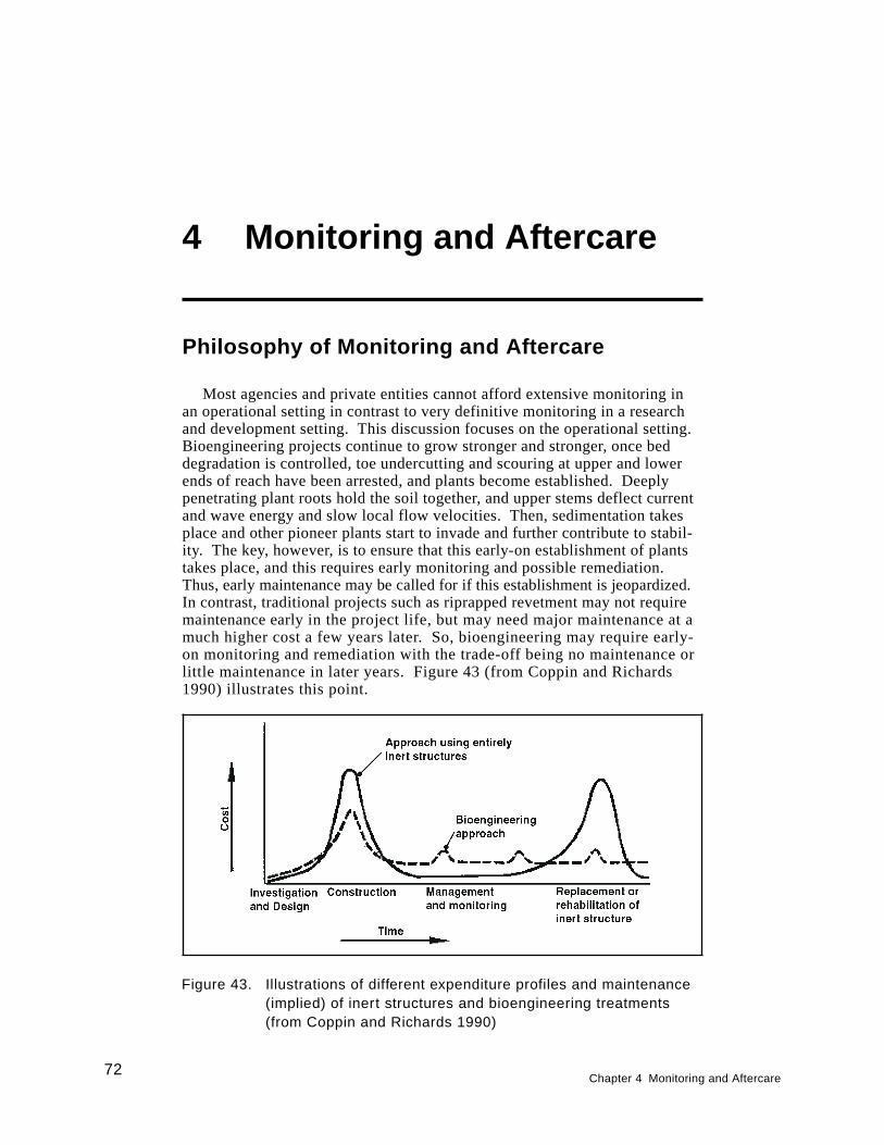
4 Monitoring and Aftercare
Philosophy of Monitoring and Aftercare
Most agencies and private entities cannot afford extensive monitoring inan operational setting in contrast to very definitive monitoring in a researchand development setting. This discussion focuses on the operational setting.Bioengineering projects continue to grow stronger and stronger, once beddegradation is controlled, toe undercutting and scouring at upper and lowerends of reach have been arrested, and plants become established. Deeplypenetrating plant roots hold the soil together, and upper stems deflect currentand wave energy and slow local flow velocities. Then, sedimentation takesplace and other pioneer plants start to invade and further contribute to stabil-ity. The key, however, is to ensure that this early-on establishment of plantstakes place, and this requires early monitoring and possible remediation.Thus, early maintenance may be called for if this establishment is jeopardized.In contrast, traditional projects such as riprapped revetment may not requiremaintenance early in the project life, but may need major maintenance at amuch higher cost a few years later. So, bioengineering may require early-on monitoring and remediation with the trade-off being no maintenance orlittle maintenance in later years. Figure 43 (from Coppin and Richards1990) illustrates this point.
Figure 43. Illustrations of different expenditure profiles and maintenance(implied) of inert structures and bioengineering treatments(from Coppin and Richards 1990)
72Chapter 4 Monitoring and Aftercare
Bioengineering projects need to be observed early after project con-struction for signs of plant survival and development, as well as forstreambank integrity. At least qualitative monitoring should be done toensure that detrimental phenomena do not jeopardize the project. For in-stance, Court Creek, Illinois, one of the project case studies discussed inReport 2 had an infestation of spider mites. Within a month or so afterplanting, spider mites had damaged almost all of the leaves on the willowthat were being used for stabilization. Without remedial spraying, projectfailure could have resulted. In another case study, North River, Massachu-setts (Report 2), a drought occurred the first year after planting and killedmuch of the planted emergent aquatic vegetation. Remedial planting hadto be done the following year to compensate for drought mortality. Also,along with vegetative development, streambank integrity needs to be ob-served to ensure that unraveling of the bank is not occurring from such ac-tions as undercutting of the toe or flanking at the upper or lower ends ofthe treated section. If this is occurring, then corrective measures need tobe taken immediately, such as placing more rock or some other hard struc-ture in those places. Projects should be monitored at least a couple ofyears after development at a minimum. Preferably, they should be moni-tored through 1-2 flood events where currents are directed on the treatedbank. One can then assess whether the site remains stable or unravels. Inthe latter case, remediation can occur. Site monitoring in bioengineeringprojects should be written into the contract specifications so that early re-mediation does not become a part of operational and maintenance costs,which often have to be budgeted separately within many agencies.
Direct Documentation of Erosion Protection
Aerial photographic monitoring
Each bioengineering reach and associated treatment, e.g., rock toe withbrush matting, vegetative geogrid, should be monitored for erosion directlyby use of aerial photogrammetric techniques. This will allow evaluationof changes occurring at the land-water interface providing the proceduresdiscussed below are used.
Aerial photo coverage should be flown at least twice a year for the first2-3 years or immediately after a flood event. Suggested times are in thespring and in the fall. Low-water periods are preferable. Photo flightsshould be highly controlled; that is, the scale of repeated flights must bethe same. A suggested scale is 1:1,000. Also, three ground control pointsof known location and dimensions should be used per frame to provide ac-curate photogrammetric measurements, and these should be orthogonallycorrected when processed to negate distortion. Recommended film type inpriority order is (a) color infrared and (b) color. To allow comparisons ofrepeated photo coverage, flights must be made during low-water periodsand when river water levels correspond to each other; that is, at or belowprevious photographic periods. Overlays can be made on the photos thatwill delineate the water-interface boundary. Subsequent overlays can becompared showing any changes in the water-interface boundary (see
Chapter 4 Monitoring and Aftercare73
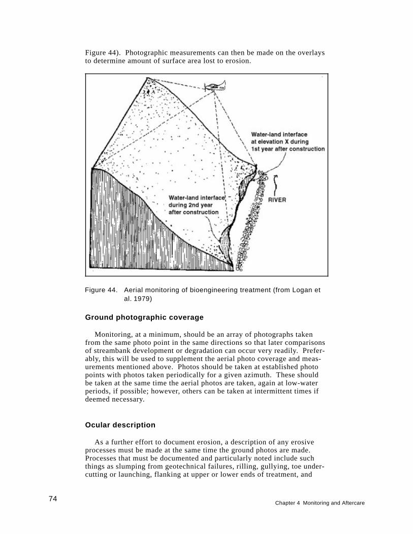
Figure 44). Photographic measurements can then be made on the overlaysto determine amount of surface area lost to erosion.
Ground photographic coverage
Monitoring, at a minimum, should be an array of photographs takenfrom the same photo point in the same directions so that later comparisonsof streambank development or degradation can occur very readily. Prefer-ably, this will be used to supplement the aerial photo coverage and meas-urements mentioned above. Photos should be taken at established photopoints with photos taken periodically for a given azimuth. These shouldbe taken at the same time the aerial photos are taken, again at low-waterperiods, if possible; however, others can be taken at intermittent times ifdeemed necessary.
Ocular description
As a further effort to document erosion, a description of any erosiveprocesses must be made at the same time the ground photos are made.Processes that must be documented and particularly noted include suchthings as slumping from geotechnical failures, rilling, gullying, toe under-cutting or launching, flanking at upper or lower ends of treatment, and
Figure 44. Aerial monitoring of bioengineering treatment (from Logan etal. 1979)
74Chapter 4 Monitoring and Aftercare
scouring at other areas within the reach from either current or wave ac-tion. Descriptive estimates of degree of severity for each of the aboveprocesses per treatment and reach with backup photos should be made.
Indirect Documentation of Erosion Protection
Erosion protection is assumed to be offered by the vegetation if theplants are surviving and developing; that is, covering the site. The devel-opment of the vegetation needs to be monitored and possibly correlated, atleast from a visual standpoint to the degree of erosion or lack of erosiontaking place on the treated streambank. One would assume, for example,that vegetative plantings are doing a good job if the vegetation is growingwell in all elevation zones in the project area and if the stream is not un-dercutting the treatments, flanking them, or scouring them to the point offailure.
Aftercare
As mentioned above, early monitoring may mean some early remedia-tion and maintenance just to ensure long-term viability. What does thisearly remediation and maintenance mean? Does this constitute periodic ir-rigation or repeated fertilizer application? It does not as a regular rule.However, plants should be well watered immediately after planting. Bioen-gineering projects are normally installed at a time of the year, such asearly spring, where precipitation is sufficient to allow the planted vegeta-tion to sprout roots and stems and obtain a foothold in its environment.Plants may also be installed in the late fall during dormancy. Repeated ir-rigation is not needed then. Hopefully, fertilizer and other soil treatmentswere applied before or during planting, if needed, and they should not berequired again, unless unusual circumstances prevail.
Possible aftercare requirements may mean bolstering a particular treat-ment with additional plants or even inert materials after an immediateflood event. Flooding may have caused some plants to wash out beforethey had a chance to secure themselves with their roots. Hopefully, engi-neered materials, such as wire, stakes, geotextile coverings, rock toes,etc., would have helped hold the plants and soil until the plants become es-tablished, but sometimes any one of these materials, either plants or inertmaterials, may need bolstering.
Other aftercare measures, as mentioned above, may mean treating plantswith an insecticide or fungicide if insects or disease is widely prevalent. Usu-ally, this will be the exception rather than the rule. One can overcomewidespread insect or disease damage by emphasizing a wide diversity ofplants in the plant mix so that if one species is attacked, the whole vegeta-tive treatment will not be jeopardized. Beaver and herbivores, such asgeese, may be a problem in some cases by feeding on woody and emergentaquatic plants, respectively. Beaver will often chew off the upper part of
Chapter 4 Monitoring and Aftercare75

willow and poplar cuttings, but these can resprout and still perform satis-factorily if the complete cutting or stem is not chewed off or dislodged.In some cases, where beaver are known to be in the area, then a trappingprogram may be advised. Waterfowl, especially geese and swans, like togrub out emergent aquatic plants as well as feed on the upper parts. Tem-porary fence corridors made out of wooden slats with tiered twine at-tached to the slats have been shown to prevent geese from feeding onemergent aquatic plants. They do not like to feel trapped inside narrowconfines where they cannot escape quickly.
76Chapter 4 Monitoring and Aftercare
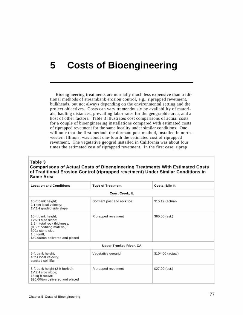
5 Costs of Bioengineering
Bioengineering treatments are normally much less expensive than tradi-tional methods of streambank erosion control, e.g., riprapped revetment,bulkheads, but not always depending on the environmental setting and theproject objectives. Costs can vary tremendously by availability of materi-als, hauling distances, prevailing labor rates for the geographic area, and ahost of other factors. Table 3 illustrates cost comparisons of actual costsfor a couple of bioengineering installations compared with estimated costsof riprapped revetment for the same locality under similar conditions. Onewill note that the first method, the dormant post method, installed in north-western Illinois, was about one-fourth the estimated cost of riprappedrevetment. The vegetative geogrid installed in California was about fourtimes the estimated cost of riprapped revetment. In the first case, riprap
Table 3Comparisons of Actual Costs of Bioengineering Treatments With Estimated Costsof Traditional Erosion Control (riprapped revetment) Under Similar Conditions inSame Area
Location and Conditions Type of Treatment Costs, $/lin ft
Court Creek, IL
10-ft bank height;3.1 fps local velocity;1V:1H graded side slope
Dormant post and rock toe $15.19 (actual)
10-ft bank height;1V:2H side slope;1.5 ft total rock thickness,(0.5 ft bedding material);300# stone size;1.5 ton/ft;$40.00/ton delivered and placed
Riprapped revetment $60.00 (est.)
Upper Truckee River, CA
6-ft bank height;4 fps local velocity;stacked soil lifts
Vegetative geogrid $104.00 (actual)
8-ft bank height (2-ft buried);1V:2H side slope;18 sq ft rock/ft;$20.00/ton delivered and placed
Riprapped revetment $27.00 (est.)
Chapter 5 Costs of Bioengineering77
was in short supply and cost much more, which, in part, contributed to ahigher cost than in the California example. Also, the dormant postmethod required cheaper materials and less labor than the vegetativegeogrid in California. Riprap in the California example was fairly cheap,and the slope distance to cover the bank was not great, contributing to acheaper installation than the vegetative geogrid. Also, the vegetativegeogrid was fairly labor intensive. Labor accounted for 66 percent of theoverall costs. However, what is not shown in the California example isthat the site is next to a valuable golf course, and the sponsor is also try-ing to provide shaded riverine aquatic (SRA) habitat for native browntrout. The vegetative geogrid can be installed on nearly a vertical slopewithout much sacrifice to the adjacent land, and it will provide the SRAhabitat shade by providing willow that overhang the banks. The riprappedrevetment option does not provide overhanging vegetation for good SRAhabitat and does require more land to accommodate shaving the bank to anacceptable construction standard for riprap. It would have required elimi-nating some of the valuable golf course land. Thus, one must consider theproject objectives and potential benefits and impacts when consideringcomparison of bioengineering methods with other traditional techniques.
When comparing bioengineering methods with traditional engineeringapplications, Coppin and Richards (1990) stated that each must be consid-ered on its merits, comparing life-cycle costs, i.e., the net present value ofinvestigation, design and construction, plus future management and re-placement. As mentioned earlier, bioengineering will require a higher in-vestment early in the project life to ensure that the living system isestablished. Then, maintenance drops off and the vegetation in the bioen-gineering treatment continues to grow, spread, and strengthen the stream-bank through its various attributes mentioned early in this report. Somemaintenance costs may be associated with the bioengineering treatmentlater in the project life, but these costs will be rather small. In contrast,the traditional treatment using inert structures, such as riprapped revet-ment, will have a high construction cost, a finite serviceable life with anelement of maintenance, and then a substantial replacement or refurbish-ment cost (Coppin and Richards 1990). Figure 43 effectively illustratesthis cost comparison (Coppin and Richards 1990).
Costs are also difficult to compare when strictly looking at currencyper unit of measure. The most common denominator for arriving at costsseems to be labor in terms of person hours it takes to build and install theparticular treatment. Then, material costs and equipment rental, etc., haveto be added onto this. The authors could not document time for all ofthe bioengineering methods mentioned in the text, but some man-powerestimates are given in the following paragraphs. Also, man-power costsare given for general applications of seeding and vegetative plantings tosupplement the bioengineering treatments.
78Chapter 5 Costs of Bioengineering
Man-Hour Costs of Bioengineering Treatments
Brush mattress or matting
The cost of the brush mattress is moderate according to Schiechtl(1980), requiring 2 to 5 man-hours per square meter. In a training sessionthat WES conducted, a crew of 20 students using hand tools installedabout 18 sq m of brush mattress at a rate of about 1 man-hour per squaremeter. This rate included harvesting the brush, cutting branches into ap-propriate lengths, and constructing the mattress. This rate of productioncompares favorably with an average rate of 0.92 sq m of brush mattressper man-hour by a leading bioengineering firm in the United States.
Brush layering
There are few references on the cost of brush layering. Schiechtl (1980)reported the cost to be low, presumably in comparison to techniques usingriprap or other similar materials. In the training session mentioned earlier,a crew of 20 students using hand tools installed about 20 m of brush layer-ing along one contour-slope in about 30 min. This equates to 2 m per man-hour. Often, costs can be reduced if machinery such as bulldozers orgraders can gain access to the shoreline site and reduce the hand labor re-quired in digging the trenches. Then, this would only require workers tofill the trenches with brush, which can also be covered with machinery.
Wattling bundles (fascines) and cuttings
Leiser (1983) reported man-hour costs for installing wattling and wil-low cuttings at Lake Tahoe, California (Table 4). These man-hour costscan be extrapolated to streambanks as well and run about 6 lin ft of wat-tling per man-hour and 46 small willow cuttings per man-hour. RobinSotir quoted an average installation rate of 5 lin ft of fascine productionper man-hour. Obviously, if one were to place a coir fabric between con-tours of wattling bundles, production rates would decrease substantially.According to Ms. Sotir,1 who has done this extensively, it would probablyhalf the amount of linear feet per man-hour.1
Chapter 5 Costs of Bioengineering79
1Personal Communication, 2 August 1996, Ms. Robin Sotir, President, Robin Sotir and
Associates, Marietta, GA.
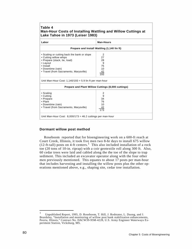
Dormant willow post method
Roseboom reported that for bioengineering work on a 600-ft reach atCourt Creek, Illinois, it took five men two 8-hr days to install 675 willow(12-ft-tall) posts on 4-ft centers.1 This also included installation of a rocktoe (20 tons of 10-in. riprap) with a coir geotextile roll along 300 ft. Also,60 cedar trees were laid and cabled along the the toe of the slope to trapsediment. This included an excavator operator along with the four othermen previously mentioned. This equates to about 17 posts per man-hourthat includes harvesting and installing the willow posts plus the other op-erations mentioned above, e.g., shaping site, cedar tree installation.
Table 4Man-Hour Costs of Installing Wattling and Willow Cuttings atLake Tahoe in 1973 (Leiser 1983)
Labor Man-Hours
Prepare and Install Wattling (1,140 lin ft)
• Scaling or cutting back the bank or slope• Cutting willow whips• Prepare (stack, tie, load)• Layout• Install• Downtime (rain)• Travel (from Sacramento, Marysville)
22728
9751042
193
Unit Man-Hour Cost: 1,140/193 = 5.9 lin ft per man-hour
Prepare and Plant Willow Cuttings (8,000 cuttings)
• Scaling• Cutting• Prepare• Plant• Downtime (rain)• Travel (from Sacramento, Marysville)
29
34761042
173
Unit Man-Hour Cost: 8,000/173 = 46.2 cuttings per man-hour
80Chapter 5 Costs of Bioengineering
1Unpublished Report, 1995, D. Roseboom, T. Hill, J. Rodstater, L. Duong, and J.
Beardsley, “Installation and monitoring of willow post bank stabilization enhancements,Peoria, Illinois,” Contract No. DACW39-95M-4228, U.S. Army Engineer Waterways Ex-periment Station, Vicksburg, MS.
Vegetative geogrid
Man-hour costs for 123 ft of a 6-ft-high vegetative geogrid installedon the Upper Truckee River that was previously mentioned included thefollowing:
Three days time of:1 Foreman/equipment operator1 Equipment operator2 Laborers1 Supervisor/project manager
Thus, 120 man-hours were expended on the above project assuming an8-hr day. This equates to about 1 man-hour per linear foot of treatedbank. About 66 percent of the costs of this treatment can be attributed tolabor.
Man-Hour Costs of Standard VegetationEstablishment Techniques to SupplementBioengineering Treatments
Standard seeding
The cost for broadcast seeding per square meter can vary considerablyaccording to some literature sources. Reported costs in man-hours persquare meter vary from 0.004 (Kay 1978) to 0.07 (Schiechtl 1980) depend-ing on the degree of slope and the type of seeds used.
Hydroseeding
Depending on the material used and the distance to adequate water,4,000 to 20,000 sq m can be hydroseeded by one hydroseeder machine perday (Schiechtl 1980). A hydroseeder normally uses a two-man crew.
Hydromulching
Mulching is often applied over seeds by a hydromulcher similar to ahydroseeding machine. For hydromulching or mechanical mulching with-out seeds, about 0.12 to 0.50 man-hours per square meter is estimated(Schiechtl 1980). Mulching after seeding increases the cost per squaremeter considerably. Hydromulching with a slurry of wood fiber, seed, andfertilizer can result in a cost of only 0.008 man-hour per square meter, ac-cording to calculations derived from Kay (1978), who reviewed contractorcosts in California. The above man-hour calculations assume the follow-ing: use of a four-man mulching machine, seed and fertilizer applied at arate of 0.75 ton per acre, and an application rate of 2 tons per hour.
Chapter 5 Costs of Bioengineering81
Sprigs, rootstocks or plugs, rhizomes, and tubers
Costs for digging grasses and other herbaceous plants in their nativehabitat and transplanting propagules of these will vary depending on theharvesting system used, the placement of the plants, and the site. For dig-ging, storing and handling, and planting 1,000 plants of sprigged wetlandgrasses and sedges, Knutson and Inskeep (1982) reported a rate of about10 man-hours. Sprigs of this type were placed on 0.5-m centers, whichwould cover 250 sq m. For the same kinds of plants, Allen, Webb, andShirley (1984) reported a rate equivalent to 400 plants per 10 man-hoursfor digging, handling, and planting single sprigs. According to Knutsonand Inskeep (1982), using plugs of any species (grass or forb) is at leastthree times more time-consuming than using sprigs (30 man-hours per1,000 plugs).
Bare-root tree or shrub seedlings
Depending on type of plant and local conditions, the reported costsof planting vary considerably. On good sites with deep soils and gentleslopes, the authors have experienced planting up to between 100 and125 plants per man-hour. Logan et al. (1979), however, estimated thatonly 200 to 400 plants per day per person could be achieved on sites likethe banks of the upper Missouri River.
Ball and burlap trees or shrubs
Planting costs for this type of transplant will range from 10 to 25 plantsper man-hour (Schiechtl 1980).
Containerized plantings
The cost of plantings varies depending on plant species, pot type, andsite conditions. By using pots other than paper, 20 to 40 plants per man-hour can be planted. With paper pots, up to 100 plants per man-hour canbe planted (Schiechtl 1980). Logan et al. (1979) stated that the cost forhand-planting containerized stock ranges from one-half the cost for bare-root seedlings to a cost equal to or exceeding that of the container seedling.
82Chapter 5 Costs of Bioengineering
6 Summary andRecommendations
Bioengineering can be a useful tool in controlling bank erosion, butshould not be considered a panacea. It needs to be performed in a prudentmanner and in consonance with good planform and channel bed stabilitydesign. It must be done with the landscape and watershed in mind, par-ticularly with respect to erosion that has occurred as a result of both broadbasinwide activities and local, site-specific causes. Nevertheless, bioengi-neering must be done at the reach level. This must be done in a system-atic way with thought given to its effects both upstream and downstream,and it may have to be done incrementally to overcome seasonal time con-straints. For instance, woody plants must be planted in the dormant sea-son. There are numerous questions that must be answered prior tobioengineering implementation. Answering these questions and designinga project must be an integrated process that starts with the planning phaseand continues through the construction phase. There are obviously feed-back loops from the design and construction phases back to the planningphase. Additional information may have to be retrieved that calls formore planning actions.
Bioengineering must be accomplished with enough hardness to preventboth undercutting of the streambank toe and erosion of the upper andlower ends (flanking) of the treated reach. This can be done with one orboth of (a) hard toe and flanking protection, e.g., rock riprap, refusals, and(b) deflection of water away from the target reach to be protected throughdeflection structures, e.g., groins, hard points, vanes, and dikes. Withboth of these methods, only appropriate plant species should be used in amanner consistent with their natural habitats. This is often done by usingstreambank zones that correspond with microhabitats of native plant speciesin local stream environments. Where possible, both herbaceous andwoody species are used with grass or grass-like plants, e.g., sedges,rushes, reed grasses, in the lower-most zone, then shrubby, woody vegeta-tion in the middle zone, and for the most part, larger shrubs and trees inthe upper-most zone. These zones are respectively called the “splash,bank, and terrace zones.”
Careful planning must be done to acquire the kinds of plants in theamounts needed. This may take up to 1 year before installation of thevarious treatments because plants either have to be grown in sufficient
Chapter 6 Summary and Recommendations83

quantities in nurseries, or they have to be located in the wild and eithercollected or grown from wild plant stock.
Bioengineering treatments have been noted, depending on the type oftreatment, to resist up to 12 fps local flow velocities. It is recognized,however, that local flow velocities during peak discharges are difficult toobtain during those events because of safety considerations. Log revet-ments with geotextile rolls in Colorado sustained velocities up to 10 fps,but undermining the lower logs occurred in the lower part of the treatedreach. A general rule of thumb is that for velocities exceeding 8 fps, somecombination of inert material be used with plants that are well secured andhave adequate toe and flank protection. The inert material may be deflec-tion structures made from root wads or rock hard points or dikes, etc., orthe inert material may be wire and stakes that hold down plant materiallong enough for that material to take hold. Even then, those materials,both inert and living plants, must have enough toe and flank protection toallow sustainment through flood events. This sustainment is especiallycritical during the early phases of the project.
Early monitoring and aftercare of a bioengineering project is essential.Each project should have incorporated into it from the beginning enoughtime and funds to provide some remedial work within the first year or soafter treatment installation. It would be better to provide this contingencyfor up to and immediately after the first one or two flood events. Onceweak spots in treatments are repaired, the bioengineered system continuesto gain strength over time.
84Chapter 6 Summary and Recommendations
References
Allen, H. H. (1978). “Role of wetland plants in erosion control of ripar-ian shorelines.”Proceedings of the National Symposium on Wetlands,American Water Resources Association, Minneapolis, Minnesota.403-414.
Allen, H. H., and Klimas, C. V. (1986). “Reservoir shoreline revegeta-tion guidelines,” Technical Report E-86-13, U.S. Army Engineer Water-ways Experiment Station, Vicksburg, MS.
Allen, H. H., Pierce, G. J., and Van Wormer, R. (1989). “Considerationsand techniques for vegetation establishment in constructed wetlands.”Constructed wetlands for wastewater treatment.D. A. Hammer, ed.,Lewis Publishers, Chelsea, MI, 405-415.
Allen, H. H., Webb, J. W., and Shirley, S. O. (1984). “Wetlands develop-ment in moderate wave-energy climates.”Proceedings of ConferenceDredging ’84, Waterway, Port, Coastal and Ocean Division, AmericanSociety of Civil Engineers, Nov. 14-16, 1984, Clearwater Beach, Florida.943-955.
Bailey, R. W., and Copeland, O. L. (1961). “Vegetation and engineeringstructures in flood and erosion control,” U.S. Department of Agricul-ture Intermountain Forest and Range Experiment Station, Ogden, Utah.Paper presented at 13th Congress of International Union of Forest Re-search Organizations, Vienna, Austria, September 10-17, 1961.
Bartos, M. J. (1979). “101 uses for earth reinforcement,”Civil Engr.49(1), 51-57.
Bowers, K. (1992). “Little Patuxent River - Stream restoration,”Landand Water,July/August.
Briggs, J. A., and Munda, B. (1992). “Collection, evaluation, selection,and production of cottonwood poles for riparian area improvement,”Final Report to the U.S. Fish and Wildlife Service, USDA-SCS, Tuc-son Plant Materials Center, Tucson, AZ.
Coppin, N. J., and Richards, I. G. (1990).Use of vegetation in civil engi-neering. Butterworths, London.
References85
Derrick, D. (1996). “The bendway weir: An in-stream erosion controland habitat improvement structure for the 1990’s.”Proceedings ofConference XXVII, February 27 -March 1, 1996, Seattle, Washington,International Erosion Control Association. 229-241.
Edminster, F. C. (1949). “Streambank plantings of erosion control in theNortheast,” U.S. Department of Agriculture Leaflet No. 258, U.S. Gov-ernment Printing Office, Washington, DC.
Edminster, F. C., Atkinson, W. S., and McIntyre, A. C. (1949). “Stream-bank erosion control on the Winooski River, Vermont,” U.S. Depart-ment of Agriculture Circular No. 837, U.S. Government PrintingOffice, Washington, DC.
Fenchel, G., Oaks, W., and Swenson, E. (1988). “Selecting desirablewoody vegetation for environmental mitigation and controlling winderosion and undesirable plants in the Rio Grande and Pecos River Val-leys of New Mexico,” Five-year interim report (1983-87), USDA-SCSLos Lunas Plant Materials Center, Los Lunas, NM.
Georgia Soil and Water Conservation. (1994). “Guidelines for stream-bank restoration,” Athens, GA.
Gray, D. H. (1977). “The influence of vegetation on slope processes inthe Great Lakes Region.”Proceedings: Workshop on the role of vege-tation in stabilization of the Great Lakes Shoreline.Great Lakes BasinCommission, Ann Arbor, MI, 5-29.
Gray, D. H., and Leiser, A. T. (1982).Biotechnical slope protection anderosion control. Van Nostrand Reinhold Co., New York.
Gray, D. H., and Sotir, R. B. (1996).Biotechnical and soil bioengineer-ing slope stabilization: A practical guide for erosion control.JohnWiley and Sons, Inc., New York.
Henderson, J. E., and Shields, F. D., Jr. (1984). “Environmental featuresfor streambank protection projects,” Technical Report E-84-11, U.S.Army Engineer Waterways Experiment Station, Vicksburg, MS.
Hoag, C. (1993). “How to plant willows and cottonwoods for riparian re-habilitation,” TN Plant Materials No. 23, September, 1993, USDA SoilConservation Service, Boise, ID.
. (1994a). “The Stinger,” TN Plant Materials No. 6, June 1994,USDA Soil Conservation Service, Boise, ID.
. (1994b). “Use of willow poles and spikes at American FallsReservoir, Idaho,” Notes from “Reservoir shoreline erosion/revegetationworkshop,” Lewisville and Ray Roberts Lakes, Denton, TX,28 March - 1 April, 1994, U.S. Army Engineer Waterways ExperimentStation, Vicksburg, MS.
86References

Hoag, J. C. (1992). “Planting techniques from the Aberdeen, ID,Plant Materials Center for vegetating shorelines and riparian areas.”Proceedings—Symposium on ecology and management of riparianshrub communities.USDA Forest Service General TechnicalReport RM-65, Rocky Mountain Forest and Range ExperimentStation, Fort Collins, CO, 163-166.
Hoag, J. C., Young, G. L., and Gibbs. (1991a). “Planting techniques forvegetative riparian areas from the Aberdeen Plant Materials Center,”Paper presented at the 45th Annual Meeting of the Society for RangeManagement, Spokane, WA.
. (1991b). “Advance regional adaptation trials of accessionsfrom the Aberdeen Plant Materials Center,” Paper presented at the 45thAnnual Meeting of the Society for Range Management, Spokane, WA.
Hunter, C. J. (1991).Better trout habitat, A guide to stream restorationand management.T. Palmer, ed., Island Press, Washington, DC.
Kay, B. L. (1978). “Mulches for erosion control and plant establishmenton disturbed sites.”Proceedings—ALCA’s 1978 Revegetation ErosionControl Symposium, August 1-3, 1978, Denver, CO. 111-129.
Klingeman, P. C., and Bradley, J. B. (1976). “Willamette River Basinstreambank stabilization by natural means,” U.S. Army Engineer Dis-trict, Portland, Portland, OR.
Knutson, P. L., Allen, H. H., and Webb, J. W. (1990). “Guidelines forvegetative erosion control on wave-impacted coastal dredged materialsites,” Technical Report D-90-13, U.S. Army Engineer Waterways Ex-periment Station, Vicksburg, MS.
Knutson, P. L., and Inskeep, M. R. (1982). “Shore erosion control withsalt marsh vegetation,” Coastal Engineering Technical Aid No. 82-3,U.S. Army Engineer Coastal Engineering Research Center, Vicksburg,MS.
Leiser, A. T. (1983). “Reservoir shoreline revegetation,” Notes fromU.S. Army Corps of Engineers training courseWetlands Developmentand Restoration, Duck, NC. (Available from U.S. Army EngineerDivision, Huntsville, AL.)
. (1992). “Biogeotechnology for slope protection and erosioncontrol,” Notes from “Reservoir Shoreline Erosion/RevegetationWorkshop,” Fergus Falls, Minnesota, June 1992, U.S. Army EngineerWaterways Experiment Station, Vicksburg, MS.
. (1994). “Biotechnical approaches for shoreline erosion con-trol,” Notes from “Reservoir Shoreline Erosion/Revegetation Work-shop,” Lewisville and Ray Roberts Lakes, Denton, TX, 28 March -1 April, 1994, U.S. Army Engineer Waterways Experiment Station,Vicksburg, MS.
References87
Leopold, L. B., and Wolman, M. G. (1957). “River channel patterns—braided, meandering, and straight,” U.S. Geological Survey Profes-sional Paper 282-B.
Lindsey, A. A., Petty, R. O., Sterling, D. K., and Van Asdall, W. (1961).“Vegetation and environment along the Wabash and Tippecanoe riv-ers,” Ecological Monographs31, 105-156.
Logan, L. D., et al. (1979). “Vegetation and mechanical systems forstreambank erosion control, guidelines for streambank erosion controlalong the banks of the Missouri River from Garrison Dam downstreamto Bismarck, North Dakota,” U.S. Army Engineer District, Omaha;USDA Forest Service, Northern Region; and North Dakota State ForestService.
Mallik, A. U. and Harun, R. (1993). “Root-shoot characteristics of ripar-ian plants in a flood control channel: Implications for bank stabiliza-tion,” Ecological Engineering2(1993), 149-158.
Miller, D. E. (1992). “Bio-engineered stream channel used to restore NewJersey brook,”Land and Water,July/August, 12-14.
Mitsch, W. J., and Gosselink, J. G. (1986).Wetlands.Van Nostrand Rein-hold, New York.
Parsons, D. A. (1963). “Vegetative control of streambank erosion.”Pro-ceedings: Federal inter-agency sedimentation conference.Agricul-tural Research Service, U.S. Department of Agriculture, 130-143.
Peterson, L. A., and Phipps, H. M. (1976). “Water soaking pretreatmentimproves rooting and early survival of hardwood cuttings of some popu-lus clones,” Tree Planter’s Notes 27(1), 12, 22.
Pierce, G. J. (1994). Notes from “Reservoir Shoreline Erosion/RevegetationWorkshop,” Lewisville and Ray Roberts Lakes, Denton, TX, 28 March -1 April, 1994, U.S. Army Engineer Waterways Experiment Station,Vicksburg, MS.
Platts, W. S., Armour, C., Booth, G. D., and others. (1987) “Methods forevaluating riparian habitats with applications to management,” USDAForest Service General Technical Report INT-221, Intermountain Re-search Station, Ogden, UT.
Roseboom, D. (1993). “Case studies on biotechnical streambank protec-tion.” Proceedings of Riparian Habitat Protection and ReconstructionSymposium, Paris Landing State Park, Nov 7-10, 1993.NonpointSource Program, Tennessee Department of Environmental Conservation.
Schiechtl, H. (1980).Bioengineering for land reclamation and conserva-tion. University of Alberta Press, Edmonton, Alberta, Canada.
88References
Schultze, R. E., and Wilcox, G. I. (1985). “Emergency measures forstreambank stabilization: An evaluation,” Paper presented at NorthAmerican Riparian Conference, Tuczon, AZ, April 1985.
Seibert, P. (1968). “Importance of natural vegetation for the protectionof the banks of streams, rivers, and canals,”Nature and EnvironmentSeries (Volume Freshwater),Council of Europe, 35-67.
Shields, F. D., Jr., Knight, S. S., and Cooper, C. M. (1995). “Incisedstream physical habitat restoration with stone weirs.”Regulated rivers:Research & management. Vol 10, John Wiley and Sons, Ltd., 181-198.
Siegel, M. (1994). “Natural stabilization of a streambank,”Land andWater,May/June, 28-31.
Sigafoos, R. S. (1964). “Botanical evidence of floods and floodplaindeposition, vegetation, and hydrologic phenomena,” U.S. GeologicalSurvey Professional Paper 485-A.
Skeesick, D. G., and Sheehan, M. C. (1993). “Blue River and DorenaReservoir shoreline erosion control vegetation survival tests.”Proceed-ings, U.S. Army Corps of Engineers Workshop on Reservoir ShorelineErosion: A National Problem, 26-30 October 1992, McAlester, OK,H. H. Allen and J. L. Tingle, eds., 125-165.
U.S. Army Corps of Engineers. (1989). “Environmental engineeringfor local flood control channels,” Engineering Manual 1110-2-1205,15 November, 1989, Washington, DC.
. (1993). “Streambank protection, Sequoyah Hills Park, Ten-nessee River, Knoxville, TN, construction solicitation and specifica-tions,” IFB No. DACW62-93-B-0041, August 1993, U.S. ArmyEngineer District, Nashville, Nashville, TN.
. (1994). “Hydraulic design of flood control channels,” Engi-neering Manual 1110-2-1601, Change 1, 30 June, 1994, Washington,DC.
U.S. Department of Agriculture. (1985). “Fish habitat improvement hand-book,” Technical Publication R8-TP7, U.S. Forest Service, SouthernRegion, Atlanta, GA.
USDA Soil Conservation Service. (1992). “Directory of Wetland PlantVendors,” Technical Report WRP-SM-1, U.S. Army Engineer Water-ways Experiment Station, Vicksburg, MS.
Vetrano, D. M. (1988). “Unit construction of trout habitat improvementstructures for Wisconsin Coulee streams,” Administrative Report No.27, Bureau of Fisheries Management, Department of Natural Re-sources, Madison, WI.
References89

Whitlow, T. H., and Harris, R. W. (1979). “Flood tolerance in plants: Astate-of-the-art review,” Technical Report E-79-2, U.S. Army EngineerWaterways Experiment Station, Vicksburg, MS.
Wolman, M. G., and Leopold, L. B. (1957). “River floodplains: Someobservations on their formation,” U.S. Geological Survey ProfessionalPaper 282-C.
90References

REPORT DOCUMENTATION PAGE Form ApprovedOMB No. 0704-0188
Public reporting burden for this collection of information is estimated to average 1 hour per response, including the time for reviewing instructions, searching existing data sources, gathering and maintainingthe data needed, and completing and reviewing the collection of information. Send comments regarding this burden estimate or any other aspect of this collection of information, including suggestionsfor reducing this burden, to Washington Headquarters Services, Directorate for Information Operations and Reports, 1215 Jefferson Davis Highway, Suite 1204, Arlington, VA 22202-4302, and to theOffice of Management and Budget, Paperwork Reduction Project (0704-0188), Washington, DC 20503.
1. AGENCY USE ONLY (Leave blank) 2. REPORT DATE 3. REPORT TYPE AND DATES COVERED
4. TITLE AND SUBTITLE 5. FUNDING NUMBERS
6. AUTHOR(S)
7. PERFORMING ORGANIZATION NAME(S) AND ADDRESS(ES) 8. PERFORMING ORGANIZATIONREPORT NUMBER
9. SPONSORING/MONITORING AGENCY NAME(S) AND ADDRESS(ES) 10. SPONSORING/MONITORINGAGENCY REPORT NUMBER
11. SUPPLEMENTARY NOTES
12a. DISTRIBUTION/AVAILABILITY STATEMENT 12b. DISTRIBUTION CODE
13. ABSTRACT (Maximum 200 words)
14. SUBJECT TERMS 15. NUMBER OF PAGES
16. PRICE CODE
17. SECURITY CLASSIFICATIONOF REPORT
18. SECURITY CLASSIFICATIONOF THIS PAGE
19. SECURITY CLASSIFICATIONOF ABSTRACT
20. LIMITATION OF ABSTRACT
NSN 7540-01-280-5500 Standard Form 298 (Rev. 2-89)Prescribed by ANSI Std. Z39-18298-102
April 1997 Report 1 of a series
Bioengineering for Streambank Erosion Control; Report 1, Guidelines
Hollis H. Allen, James R. Leech
U.S. Army Engineer Waterways Experiment Station3909 Halls Ferry RoadVicksburg, MS 39180-6199
Technical Report EL-97-8
U.S. Army Corps of EngineersWashington, DC 20314-1000
Available from National Technical Information Service, 5285 Port Royal Road, Springfield, VA 22161.
Approved for public release; distribution is unlimited.
Bioengineering Streambank stabilizationBioengineering guidelines Wetland vegetationRiparian vegetation
103
UNCLASSIFIED UNCLASSIFIED
This study provides guidelines for using bioengineering treatments in a prudent manner while tempering their widespreaduse with precautions. Precautions consist of properly designing bioengineering projects with enough hardness to prevent bothundercutting the streambank toe and erosion of the upper and lower ends (flanking) of the treated project reach. This can beaccomplished with one or both of (a) hard toe and flanking protection, e.g., rock riprap, refusals, and (b) deflection of wateraway from the target reach to be protected through deflection structures, e.g., groins, hard points, and dikes. With both ofthese methods, appropriate plant species should be used in a manner consistent with their natural habitats; that is, in an effortto emulate natural conditions or processes. This is often done with streambank zones that more or less correspond withmicrohabitats of native plant species in local stream environments. Where possible, both herbaceous and woody species areused with grass or grass-like plants in the lower most zone that is planted; shrubby, woody vegetation is used in the middlezone; and, for the most part, larger shrubs and trees are established in the upper most zone. These zones are respectivelycalled the “splash, bank, and terrace zones.”

Destroy this report when no longer needed. Do not return it to the originator.