booster packet liquids propulsion design … · booster packet liquids propulsion design team...
TRANSCRIPT

1
BOOSTER PACKET
LIQUIDS PROPULSION DESIGN TEAM
Welcome to the UF Liquid Propulsion Design Team! This packet is designed to help you
understand what our team is all about and get you up to speed on some of the basics of rocket
propulsion science. We meet every Monday at 5:10 PM in LIT 0207, feel free to join in!
OUR GOAL To design, manufacture, and test low-cost liquid-propelled rocket engines. In addition to engine
development, we will look ahead to creating a full-scale rocket, powered by one of our propulsion
systems, that will participate in the Spaceport America Cup.
TEAM OVERVIEW Our team is divided into sub-teams focused on different systems of our rocket engines. These
are: Propellant Delivery, Mechanical Design, Structural Analysis, Thermal Fluid Analysis,
Electronics, Manufacturing, and Systems. Each sub-team calls for unique expertise, and they all
must work together to make a functional engine. Currently we are in development of a mid-
performance bi-propellant rocket engine, nicknamed the Albatross Engine.

2
SVE – SOFTWARE VERIF ICATION ENGINE The SVE is the LPDT’s first propulsion system development effort. SVE’s primary objectives were
to validate the software and design methods used in development, serve as a proof of concept
for a low-cost propulsion system, and establish a baseline for hands-on design, manufacturing,
and testing. The SVE was designed with mechanical simplicity and operational safety in mind.
Propellants
• Fuel: 95% Ethanol
• Oxidizer: 50% Hydrogen Peroxide
Features
• Pressure-Fed Cycle
• Automated control and operation
• Static Tests Conducted
• ~150 N thrust
• Steel and Aluminum Construction

3
PROPELLANT DELIVERY
The Propellant Delivery System sub-team is dedicated to figuring out how we move the
propellants from the tank into the chamber. There are many ways of pushing the propellants into
the chamber, however we are going to look at the two most common methods: pressurized gas
propellant feed system and a pump propellant feed system.
PRESSURIZED GAS PROPELLANT FEED SYSTEM
A separate gas supply, usually helium,
pressurizes the propellant tanks to force fuel
and oxidizer to the combustion chamber. To
maintain adequate flow, the tank pressures
must exceed the combustion chamber
pressure. Pressure fed engines have simple
plumbing and lack complex and often
unreliable turbopumps.
Pressure-fed engines have practical limits on
propellant pressure, which in turn limits
combustion chamber pressure. High pressure
propellant tanks require thicker walls and
stronger alloys which make the vehicle tanks
heavier, thereby reducing performance and
payload capacity.
4
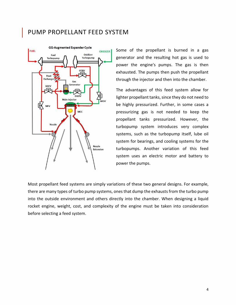
PUMP PROPELLANT FEED SYSTEM
Some of the propellant is burned in a gas
generator and the resulting hot gas is used to
power the engine's pumps. The gas is then
exhausted. The pumps then push the propellant
through the injector and then into the chamber.
The advantages of this feed system allow for
lighter propellant tanks, since they do not need to
be highly pressurized. Further, in some cases a
pressurizing gas is not needed to keep the
propellant tanks pressurized. However, the
turbopump system introduces very complex
systems, such as the turbopump itself, lube oil
system for bearings, and cooling systems for the
turbopumps. Another variation of this feed
system uses an electric motor and battery to
power the pumps.
Most propellant feed systems are simply variations of these two general designs. For example,
there are many types of turbo pump systems, ones that dump the exhausts from the turbo pump
into the outside environment and others directly into the chamber. When designing a liquid
rocket engine, weight, cost, and complexity of the engine must be taken into consideration
before selecting a feed system.

5
MECHANICAL DESIGN The Mechanical Design sub-team is responsible for developing the design for the rocket’s
chamber, nozzle, cooling systems, injectors and many other components. This team combines
advanced calculations with engineering creativity to create functional and efficient engine
components. The Mechanical Design sub-team emphaiszes design simplicity, affordability, and
manufacturability.
CHAMBER & NOZZLE The chamber (1) is where combustion
takes place. The reduced section (t) is
called the nozzle throat; here the flow
of hot combustion gases becomes
sonic (M=1). The nozzle exit (2) is
where the hot combustion gases leave
the engine and provide the thrust for
the rocket. The equation below is the
governing equation for the thrust
force of a rocket engine.
INJECTOR The injector is located at the forward end of the
combustion chamber. It is typically bolted onto
the chamber via flanges located on the exterior of
the chamber. The injector’s main objective is to
atomize the fuel and oxidizer into the combustion
chamber while also ensuring proper mixing. A
homogenous atomized fuel and oxidizer mixture is
crucial to the performance of the engine, and
helps mitigate problems that can arise during the
combustion process, such as wall streaking or
excessive thermal flux on wall chambers.
6
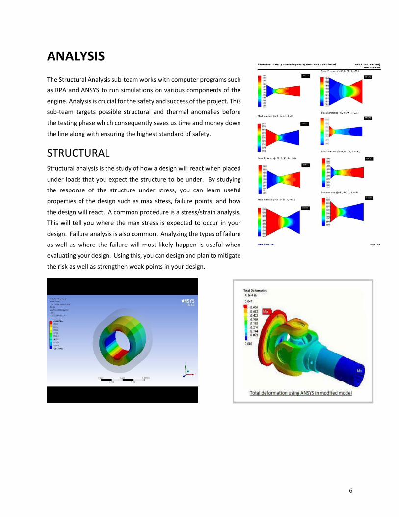
ANALYSIS
The Structural Analysis sub-team works with computer programs such
as RPA and ANSYS to run simulations on various components of the
engine. Analysis is crucial for the safety and success of the project. This
sub-team targets possible structural and thermal anomalies before
the testing phase which consequently saves us time and money down
the line along with ensuring the highest standard of safety.
STRUCTURAL Structural analysis is the study of how a design will react when placed
under loads that you expect the structure to be under. By studying
the response of the structure under stress, you can learn useful
properties of the design such as max stress, failure points, and how
the design will react. A common procedure is a stress/strain analysis.
This will tell you where the max stress is expected to occur in your
design. Failure analysis is also common. Analyzing the types of failure
as well as where the failure will most likely happen is useful when
evaluating your design. Using this, you can design and plan to mitigate
the risk as well as strengthen weak points in your design.

7
THERMAL FLUIDS Uses CFD software, ANSYS Fluent, to simulate
fluid flow through components of a rocket
engine to verify performance before actual
testing.
OUR MISSION To make sure our rocket engine is producing the most optimized thrust (force that moves the
rocket) to propel the rocket as precisely as possible while keeping the flow safe and under
control. We realize this and gage our designs through CFD simulations.
WHAT IS CFD? Computational Fluid Dynamics is the process of numerically solving a set of equations that govern
fluid motion. CFD is a three-step process:
1) Pre-Processing
a) Geometry
b) Computation grid generation
2) Solver
a) Solution of the discretized Equations of Motion
b) Convergence and Stability
3) Post-Processing
a) Inspection of solution
b) Graphing and representation of results
PRE-PROCSSING During pre-processing, we will import the geometry of
the rocket component such as the injector, propellant
pipes, combustion chamber or nozzle. We want to
simulate the mass flow rates and pressure drops
through these components to verify that we’re getting
the right number for optimal thrust.
We generate a computational grid overlaid onto each
component where the equations of motion are solved
locally - we’re basically generating a mesh where these
equations are solved in small regions that make up the
bigger picture.
8
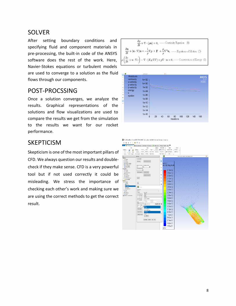
SOLVER After setting boundary conditions and
specifying fluid and component materials in
pre-processing, the built-in code of the ANSYS
software does the rest of the work. Here,
Navier-Stokes equations or turbulent models
are used to converge to a solution as the fluid
flows through our components.
POST-PROCSSING Once a solution converges, we analyze the
results. Graphical representations of the
solutions and flow visualizations are used to
compare the results we get from the simulation
to the results we want for our rocket
performance.
SKEPTICISM
Skepticism is one of the most important pillars of
CFD. We always question our results and double-
check if they make sense. CFD is a very powerful
tool but if not used correctly it could be
misleading. We stress the importance of
checking each other’s work and making sure we
are using the correct methods to get the correct
result.
9
ELECTRONICS The Electronics sub-team works to design and build all electrical components of the engine and
testing instruments. The primary focus of testing electronics is developing an Engine Health
Control system to monitor the status of the engine during testing. This system can be broken
down into data acquisition, wiring, and testing and data analysis. After extensive testing the
design of the rocket will progress towards flight, which mandates flight controller electronics
housed in an avionics subsystem.
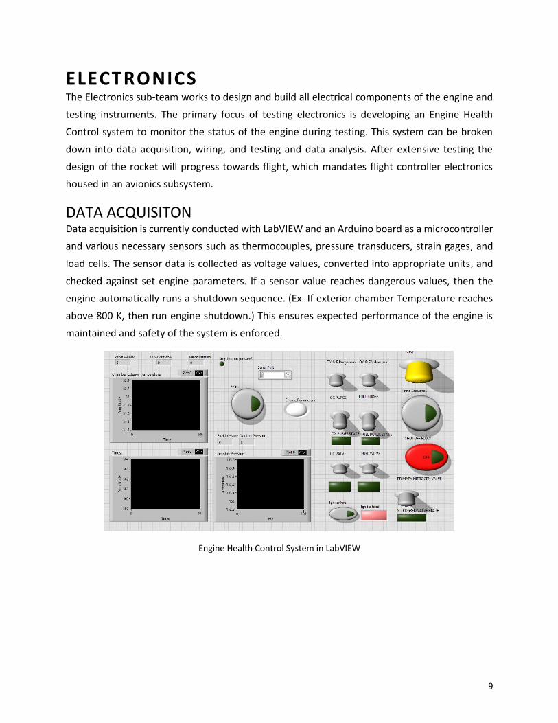
DATA ACQUISITON Data acquisition is currently conducted with LabVIEW and an Arduino board as a microcontroller
and various necessary sensors such as thermocouples, pressure transducers, strain gages, and
load cells. The sensor data is collected as voltage values, converted into appropriate units, and
checked against set engine parameters. If a sensor value reaches dangerous values, then the
engine automatically runs a shutdown sequence. (Ex. If exterior chamber Temperature reaches
above 800 K, then run engine shutdown.) This ensures expected performance of the engine is
maintained and safety of the system is enforced.
Engine Health Control System in LabVIEW
10
SENSOR TERMINOLOGY Excitation voltage: the power required to run a sensor
Signal: the information that a sensor outputs
DAQ: a device that turns raw signals into something a computer understands.
Thermocouples: these sensors utilize a changing resistance to measure temperature. This
means they require no excitation voltage. Different thermocouples can tolerate and measure
different temperatures.
Pressure transducer: measures pressure and usually requires excitation. Must be sealed to
provide accurate readings.
Load Cell: measures amount of load applied to the sensor; used for measuring engine thrust.
Strain Gage: measures strain in an axial direction of the sensor, which can be used to solve for
stress and pressure values inside of pressure vessels or the combustion chamber.
RF: Radio frequency modules are used for data transfer over a long distance. This is useful
during flight as well as during testing to maintain a proper safety distance from the test engine.
Altimeter: measures altitude of the rocket during flight using ambient pressure values.
WIRING The wiring process begins after creating the data acquisition system. Once all sensors are planned
and the software is written sensors can be purchased and tested to learn their capabilities,
limitations and how to wire them. This information is then recorded and made into a wiring
diagram for the full system. The wiring diagram can then be utilized to create the data acquisition
system. Wiring includes cutting, stripping, twisting, soldering and heat shrinking wires.
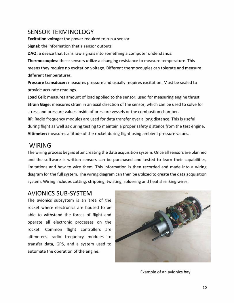
AVIONICS SUB-SYSTEM The avionics subsystem is an area of the
rocket where electronics are housed to be
able to withstand the forces of flight and
operate all electronic processes on the
rocket. Common flight controllers are
altimeters, radio frequency modules to
transfer data, GPS, and a system used to
automate the operation of the engine.
Example of an avionics bay
11
MANUFACTURING The Manufacturing sub-team cooperates with the all other teams to efficiently create parts from
various materials. This sub-team includes researching manufacturing techniques, solid model and
drawing generation, and experience with manual and CNC machining.
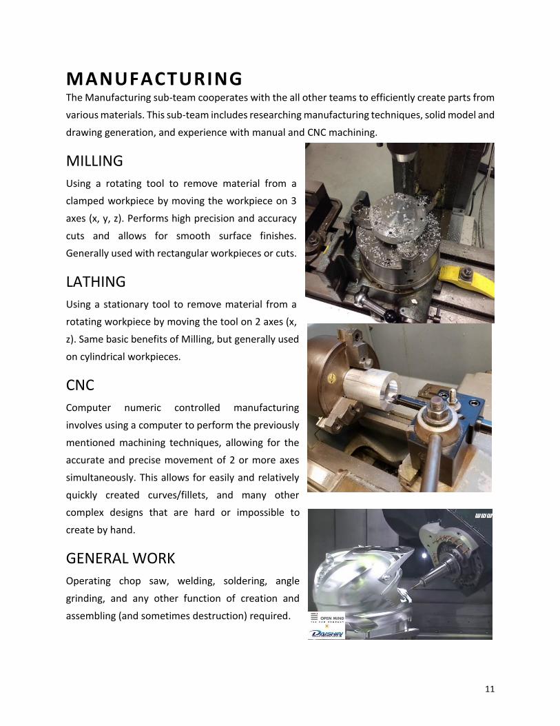
MILLING
Using a rotating tool to remove material from a
clamped workpiece by moving the workpiece on 3
axes (x, y, z). Performs high precision and accuracy
cuts and allows for smooth surface finishes.
Generally used with rectangular workpieces or cuts.
LATHING
Using a stationary tool to remove material from a
rotating workpiece by moving the tool on 2 axes (x,
z). Same basic benefits of Milling, but generally used
on cylindrical workpieces.
CNC
Computer numeric controlled manufacturing
involves using a computer to perform the previously
mentioned machining techniques, allowing for the
accurate and precise movement of 2 or more axes
simultaneously. This allows for easily and relatively
quickly created curves/fillets, and many other
complex designs that are hard or impossible to
create by hand.
GENERAL WORK
Operating chop saw, welding, soldering, angle
grinding, and any other function of creation and
assembling (and sometimes destruction) required.

12
SYSTEMS The purpose of Systems is to function as a bridge between all other sub-teams, coordinating the work done to
ensure the entire propulsion system preforms properly. Systems lays out the design requirements for each
engine sub-system placing an emphasis on safety, cost, and complexity. The team will then serve to advise the
Mechanical Design, Propellant Delivery, and Electronics sub-teams on the design of their components. The
Systems sub-team will also plan and help conduct tests to characterize the function of the engine and its
different subsystems as well as provide information to aid in component design. A good understanding of all
the engine subsystems is needed to perform these tasks
DESIGN CONSTRAINTS Design constraints are limitations placed on the design of a component. They can affect things like the
dimensions of a component, types of sensors purchased, or the materials used in construction. These can come
from several sources like other components of the engine, the testing cell or stand, the flight vehicle, or even
competition requirements. When only a few components interact with each other these can be simple to
manage, but in a more complicated engine they are much harder to handle. Temperature, pressure, mass,
dimensions of other components, and chemical properties are just a few of the examples of constraints placed
on engine design.
TESTING A test of the engine and its subsystem is a complicated undertaking. It requires a lot of events to be executed
perfectly in short succession on order for it to be successful. Putting together a procedure is essential to the
success of a test. It helps keep everyone helping with the test on track and focused. It also shows officials with
the University and emergency services our plans and how best to help us.
Another part of planning for testing is characterizing the way the engine will fail. One way to do this is a Failure
Mode Effects and Criticality analysis (FMECA). These consider all the ways the engine could fail and ranks the
likelihood of the failures occurring against how bad a failure would be. For example, a sensor failing would be
more likely to occur than an oxidizer leak but the latter would be more severe. A way of finding the probability
of failure caused by a specific component is a fault tree analysis. This forms a mathematical model of the engine
by tracing all the parts that interact with each other during operation.