brief instructions starter set uk - ifm.com · the starter set allows to set up a control system...
TRANSCRIPT
Brief instructions
Starter set BasicController
BasicRelay BasicDisplay
EC0400
7390
870
/ 00
03 /
2011
UK
Starter set BasicController
2
Contents1 Preliminary note � � � � � � � � � � � � � � � � � � � � � � � � � � � � � � � � � � � � � � � � � � � � � � � � � 4
1�1 Symbols used� � � � � � � � � � � � � � � � � � � � � � � � � � � � � � � � � � � � � � � � � � � � � � � 41�2 Warning signs used � � � � � � � � � � � � � � � � � � � � � � � � � � � � � � � � � � � � � � � � � � 41�3 General� � � � � � � � � � � � � � � � � � � � � � � � � � � � � � � � � � � � � � � � � � � � � � � � � � � � 51�4 Target group � � � � � � � � � � � � � � � � � � � � � � � � � � � � � � � � � � � � � � � � � � � � � � � � 51�5 Electrical connection � � � � � � � � � � � � � � � � � � � � � � � � � � � � � � � � � � � � � � � � � 51�6 Tampering with the device � � � � � � � � � � � � � � � � � � � � � � � � � � � � � � � � � � � � � 51�7 Electromagnetic compatibility� � � � � � � � � � � � � � � � � � � � � � � � � � � � � � � � � � � 5
2 Items supplied� � � � � � � � � � � � � � � � � � � � � � � � � � � � � � � � � � � � � � � � � � � � � � � � � � � 62�1 Devices� � � � � � � � � � � � � � � � � � � � � � � � � � � � � � � � � � � � � � � � � � � � � � � � � � � � 62�2 Prewired connection cables � � � � � � � � � � � � � � � � � � � � � � � � � � � � � � � � � � � � 62�3 Software and documentation � � � � � � � � � � � � � � � � � � � � � � � � � � � � � � � � � � � 6
2�3�1 Demo programs � � � � � � � � � � � � � � � � � � � � � � � � � � � � � � � � � � � � � � � � � 72�3�2 Tools� � � � � � � � � � � � � � � � � � � � � � � � � � � � � � � � � � � � � � � � � � � � � � � � � � 72�3�3 Documentation� � � � � � � � � � � � � � � � � � � � � � � � � � � � � � � � � � � � � � � � � � 7
3 System requirements � � � � � � � � � � � � � � � � � � � � � � � � � � � � � � � � � � � � � � � � � � � � � 73�1 Hardware � � � � � � � � � � � � � � � � � � � � � � � � � � � � � � � � � � � � � � � � � � � � � � � � � � 73�2 Software � � � � � � � � � � � � � � � � � � � � � � � � � � � � � � � � � � � � � � � � � � � � � � � � � � � 7
4 Functions and features � � � � � � � � � � � � � � � � � � � � � � � � � � � � � � � � � � � � � � � � � � � � 84�1 General� � � � � � � � � � � � � � � � � � � � � � � � � � � � � � � � � � � � � � � � � � � � � � � � � � � � 84�2 Setting up the control system � � � � � � � � � � � � � � � � � � � � � � � � � � � � � � � � � � 84�3 Features of the components at a glance � � � � � � � � � � � � � � � � � � � � � � � � � � 9
4�3�1 BasicController CR0403 � � � � � � � � � � � � � � � � � � � � � � � � � � � � � � � � � � 94�3�2 BasicRelay CR0421� � � � � � � � � � � � � � � � � � � � � � � � � � � � � � � � � � � � � � 94�3�3 BasicDisplay CR0451 � � � � � � � � � � � � � � � � � � � � � � � � � � � � � � � � � � � � 94�3�4 Cover EC0402 � � � � � � � � � � � � � � � � � � � � � � � � � � � � � � � � � � � � � � � � � � 94�3�5 CAN interface CANfox EC2112 � � � � � � � � � � � � � � � � � � � � � � � � � � � � � 94�3�6 Programming software CoDeSys� � � � � � � � � � � � � � � � � � � � � � � � � � � 10
4�4 Additional information (DVD) � � � � � � � � � � � � � � � � � � � � � � � � � � � � � � � � � � �115 Installation� � � � � � � � � � � � � � � � � � � � � � � � � � � � � � � � � � � � � � � � � � � � � � � � � � � � � 136 Electrical connection� � � � � � � � � � � � � � � � � � � � � � � � � � � � � � � � � � � � � � � � � � � � � 14
6�1 General� � � � � � � � � � � � � � � � � � � � � � � � � � � � � � � � � � � � � � � � � � � � � � � � � � � 146�2 BasicRelay � � � � � � � � � � � � � � � � � � � � � � � � � � � � � � � � � � � � � � � � � � � � � � � � 14
6�2�1 Remove the wiring carrier from the base plate � � � � � � � � � � � � � � � � 146�2�2 Specified placement� � � � � � � � � � � � � � � � � � � � � � � � � � � � � � � � � � � � � 156�2�3 Relay connection � � � � � � � � � � � � � � � � � � � � � � � � � � � � � � � � � � � � � � � 15
6�3 Supply devices � � � � � � � � � � � � � � � � � � � � � � � � � � � � � � � � � � � � � � � � � � � � � 166�4 Connection cable relay controller � � � � � � � � � � � � � � � � � � � � � � � � � � � � � � � 176�5 Supply outputs � � � � � � � � � � � � � � � � � � � � � � � � � � � � � � � � � � � � � � � � � � � � � 186�6 Ground connection � � � � � � � � � � � � � � � � � � � � � � � � � � � � � � � � � � � � � � � � � � 196�7 Relay connection � � � � � � � � � � � � � � � � � � � � � � � � � � � � � � � � � � � � � � � � � � � 206�8 Programming cables � � � � � � � � � � � � � � � � � � � � � � � � � � � � � � � � � � � � � � � � 21
UK
Starter set BasicController
3
6�9 CAN adapter cable and CAN interface CANfox � � � � � � � � � � � � � � � � � � � � 226�10 Plug-in power supply � � � � � � � � � � � � � � � � � � � � � � � � � � � � � � � � � � � � � � � 236�11 Inputs and relay switching outputs � � � � � � � � � � � � � � � � � � � � � � � � � � � � � 23
7 Set-up � � � � � � � � � � � � � � � � � � � � � � � � � � � � � � � � � � � � � � � � � � � � � � � � � � � � � � � � 247�1 Getting started � � � � � � � � � � � � � � � � � � � � � � � � � � � � � � � � � � � � � � � � � � � � � 24
7�1�1 Structure of the preinstalled control system � � � � � � � � � � � � � � � � � � 247�1�2 Download your own applications � � � � � � � � � � � � � � � � � � � � � � � � � � � 24
7�2 Programming � � � � � � � � � � � � � � � � � � � � � � � � � � � � � � � � � � � � � � � � � � � � � � 247�3 Required documentation � � � � � � � � � � � � � � � � � � � � � � � � � � � � � � � � � � � � � 247�4 Overview software � � � � � � � � � � � � � � � � � � � � � � � � � � � � � � � � � � � � � � � � � � 25
7�4�1 Install CoDeSys and Maintenance Tool � � � � � � � � � � � � � � � � � � � � � � 257�4�2 Directories on the PC/notebook � � � � � � � � � � � � � � � � � � � � � � � � � � � � 257�4�3 Load the operating system into the controller � � � � � � � � � � � � � � � � � 25
8 Operation � � � � � � � � � � � � � � � � � � � � � � � � � � � � � � � � � � � � � � � � � � � � � � � � � � � � � 268�1 Operation display � � � � � � � � � � � � � � � � � � � � � � � � � � � � � � � � � � � � � � � � � � � 268�2 Operating states � � � � � � � � � � � � � � � � � � � � � � � � � � � � � � � � � � � � � � � � � � � � 26
9 Technical data� � � � � � � � � � � � � � � � � � � � � � � � � � � � � � � � � � � � � � � � � � � � � � � � � � 279�1 Additional information � � � � � � � � � � � � � � � � � � � � � � � � � � � � � � � � � � � � � � � � 27
This document is the original instructions�
Licences and trademarksMicrosoft®, Windows®, Windows XP®, Windows Vista® and Windows 7® are registered trademarks of Microsoft Corporation� All trademarks and company names are subject to the copyright of the respective companies�
Starter set BasicController
4
1 Preliminary noteThis document applies to devices of the "BasicController starter set" (art� no�: EC0400)� These instructions are part of the device�This document is intended for specialists� These specialists are people who are qualified by their appropriate training and their experience to see risks and to avoid possible hazards that may be caused during operation or maintenance of the device� The document contains information about the correct handling of the device�Read this document before use to familiarise yourself with operating conditions, installation and operation� Keep this document during the entire duration of use of the device�Adhere to the safety instructions�
1.1 Symbols used► Instructions> Reaction, result[…] Designation of pushbuttons, buttons or indications→ Cross-reference
Important note Non-compliance can result in malfunction or interference�Information Supplementary note
1.2 Warning signs used
WARNINGWarning of serious personal injury� Death or serious irreversible injuries may result�
CAUTION Warning of personal injury� Slight reversible injuries may result�
NOTEWarning of damage to property�
UK
Starter set BasicController
5
Safety instructions1.3 GeneralThese instructions contain texts and figures concerning the correct handling of the device and must be read before installation or use�Observe the operating instructions� Non-observance of the instructions, operation which is not in accordance with use as prescribed below, wrong installation or incorrect handling can seriously affect the safety of operators and machinery�
1.4 Target groupThese instructions are intended for authorised persons according to the EMC and low-voltage directives� The device must only be installed, connected and put into operation by a qualified electrician�
1.5 Electrical connectionTo avoid risks for persons and material, voltage supply of the device must be made using the supplied power supply�All statements in these instructions refer to the device operated with the supplied power supply and the prewired connection cable�The connection terminals may only be supplied with the signals indicated in the technical data and/or on the device label and only the approved accessories of ifm electronic gmbh may be connected�
1.6 Tampering with the deviceIn case of malfunctions or uncertainties please contact the manufacturer� Tampering with the device can seriously affect the safety of operators and machinery� It is not permitted and leads to the exclusion of any liability and warranty claims�
1.7 Electromagnetic compatibilityThis is a class A installation� It can cause radio interference in domestic areas� In this case the operator is requested to take appropriate measures�
Starter set BasicController
6
2 Items supplied2.1 Devices
Pcs. Designation Description Art. no.
1 BasicController mini controller for mobile applications CR0403
1 BasicRelay wiring, relay and fuse carrier CR0421
1 BasicDisplay programmable display with graphic capabilities CR0451
1 Cover with built-in display recess and cable seal EC0402
1 CAN interface CANfox CAN/RS232 USB interface EC2112
1 Plug-in power supply 230 V AC, 50 Hz / 24 V DC (incl� mains adapter) EC2059
2 Relay 24 V DC, changeover contact –
5 Fuses 1 x 3 A (violet), 4 x 15 A (blue) –
2.2 Prewired connection cables
Pcs. Designation Connections
1 Supply devices BasicRelay − plug-in power supply (→ 6.3)
1 Connection cable BasicRelay − BasicController − BasicDisplay (→ 6.4)
2 Supply outputs BasicRelay (fuse) − BasicRelay (switching output) (→ 6.5)
1 Ground connection BasicRelay (relay GND) (→ 6.6)
1 Relay connection BasicRelay (relay coil) − BasicController (output) (→ 6.7)
1 Programming cable CAN − BasicController − BasicDisplay (→ 6.8)
2 CANfox adapter cable 1 CAN adapter cable1 RS 232 adapter cable (not used for the starter set)
(→ 6.9)
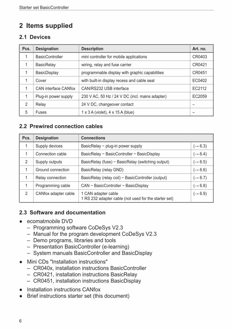
2.3 Software and documentation ● ecomatmobile DVD
– Programming software CoDeSys V2�3 – Manual for the program development CoDeSys V2�3 – Demo programs, libraries and tools – Presentation BasicController (e-learning) – System manuals BasicController and BasicDisplay
● Mini CDs "Installation instructions" – CR040x, installation instructions BasicController – CR0421, installation instructions BasicRelay – CR0451, installation instructions BasicDisplay
● Installation instructions CANfox ● Brief instructions starter set (this document)
UK
Starter set BasicController
7
2.3.1 Demo programsThe DVD contains demo programs to provide the user with a comprehensible overview of selected functions�These demo programs are automatically copied to the hard disk during the installation of CoDeSys (→ 7.4.2 Directories on the PC/notebook)� The demo programs are started directly from the programming surface of the CoDeSys program�
2.3.2 ToolsThe DVD contains software tools for installation and updates of the operating system as well as for CAN bus analysis and protocolling�
2.3.3 DocumentationFor more details, manuals concerning the controller and the programming software CoDeSys are stored on the DVD�They are in PDF format and can be read or printed using the program Adobe Reader ®� The Adobe Reader ® can be downloaded free of charge at www�adobe�com�
3 System requirements3.1 Hardware
● Pentium III processor (or higher) ● 512 MB RAM memory (or higher) ● 800 MB free hard disk memory ● DVD drive ● 1 free USB interface ● screen resolution 1024 x 768 ● 32-bit colour depth (recommended)
3.2 Software ● Microsoft Windows XP ® (SP1) ● Adobe Flash 8�0
Starter set BasicController
8
4 Functions and features4.1 GeneralThe starter set serves as an introduction into the ecomatmobile Basic series and into the programming system CoDeSys� All components are very easy to install� All required connections are prewired�
WARNINGThe BasicController series is not approved for safety tasks in the field of safety of persons�
NOTEUse of the prewired connection cables in conjunction with controllers from other manufacturers can lead to destruction of the controllers�
► The prewired connection cables may only be used with the supplied devices�
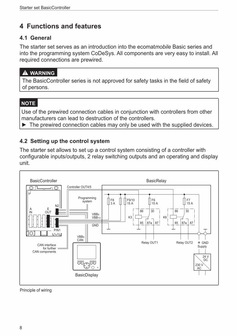
4.2 Setting up the control system The starter set allows to set up a control system consisting of a controller with configurable inputs/outputs, 2 relay switching outputs and an operating and display unit�
EOUT
AIN
K3
86 30
85 87a 87
K6
86 30
85 87a 87
BasicController BasicRelay
BasicDisplay
GNDRelay OUT1 Relay OUT2
VBBSCAN
VBBSVBB1/2
GND
Controller OUT4/5
F83 A
F9/1015 A
F615 A
F715 A
Programmingsystem
Supply
24 VDC
230 VAC
CAN interfacefor further
CAN components
N2
P/N1
Principle of wiring
UK
Starter set BasicController
9
4.3 Features of the components at a glance
4.3.1 BasicController CR0403 ● Usable as CANopen master or intelligent I/O module ● Free programming according to IEC 61131-3 ● 2 CAN interfaces (incl� interface for BasicDisplay CR0451) ● SAE J 1939 (engine interface) and CAN Layer 2 ● Configurable inputs/outputs ● Protection IP 20 (with cover and cable seal IP 54) ● Status LED
4.3.2 BasicRelay CR0421 ● Locations for 6 automotive relays and 10 automotive fuses ● Supply chain can be cut ● Power distributor for 6�3 mm male blade terminals
4.3.3 BasicDisplay CR0451 ● 2�8" colour display ● 5 freely programmable backlit function keys ● Rocker switch for cursor function ● CAN interface ● Free programming according to IEC 61131-3 with target visualisation
4.3.4 Cover EC0402 ● Can be used for BasicController CR040x ● Built-in display recess for BasicDisplay CR0451 ● Single-lever locking
4.3.5 CAN interface CANfox EC2112 ● Operating voltage via USB (5 V DC) ● Interfaces electrically isolated ● CAN baud rate freely selectable ● 11 and 29-bit identifiers ● Can be used with CoDeSys (2�3�9�21 or higher), Maintenance Tool or
CANexplorer
Starter set BasicController
10
4.3.6 Programming software CoDeSysCoDeSys is a complete development environment for ecomatmobile controllers� With this environment the PLC programmer can conveniently use the programming languages to IEC 61131-3�CoDeSys provides the following functions and features:
● Programming of the controller according to the standard IEC 61131-3 – function block diagram (FBD) – ladder diagram (LD) – instruction list (IL) – sequential function chart (SFC) – structured text (ST)
● Visualisation and diagnosis of the available controller data ● Setting of all communication parameters of the connected controller hardware ● Convenient editors conforming to Windows representation ● Extensive debugging, test and diagnostic tools ● Program simulation online / offline ● Detailed documentation and online help ● Exchange of data with other Windows programs via DDE interface
UK
Starter set BasicController
11
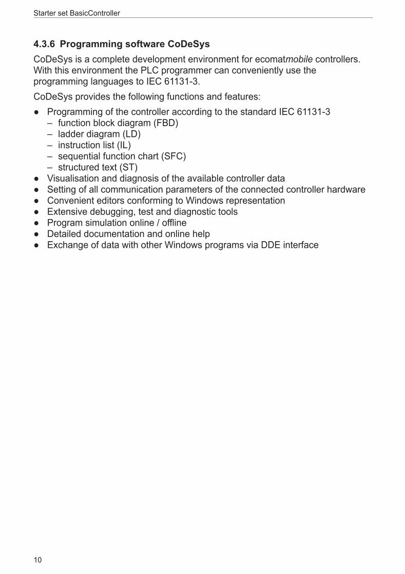
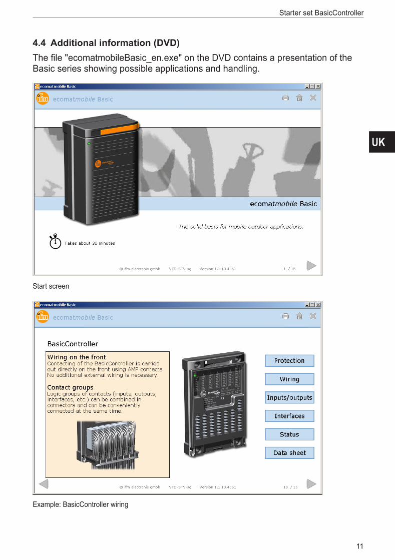
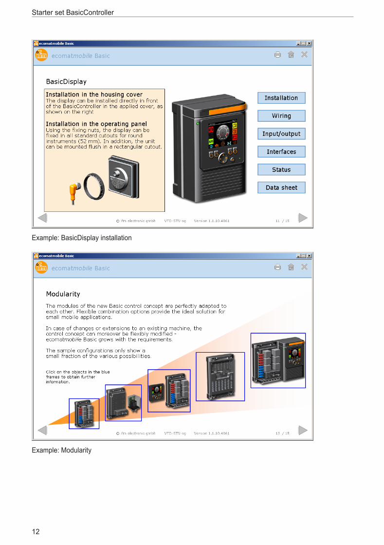
4.4 Additional information (DVD)The file "ecomatmobileBasic_en�exe" on the DVD contains a presentation of the Basic series showing possible applications and handling�
Start screen
Example: BasicController wiring
Starter set BasicController
12
Example: BasicDisplay installation
Example: Modularity
UK
Starter set BasicController
13
5 Installation ► Observe the installation instructions and the technical data�This applies mainly to the case where the devices are integrated and installed in an application permanently�
Among others the installation instructions contain the following: ● requirements for fixing or mounting the devices ● handling of the cover and the cable seal ● general wiring information ● technical data ● test standards and regulations ● wiring diagrams
The supplied mini CD's contain the installation instructions of the Basic components (→ 2.3 Software and documentation).
The supplied EC0402 cover cannot be used for the BasicRelay�
Starter set BasicController
14
6 Electrical connection6.1 General
► Connect the units to the supplied connection cables.(→ 4.2 Setting up the control system)
6.2 BasicRelay
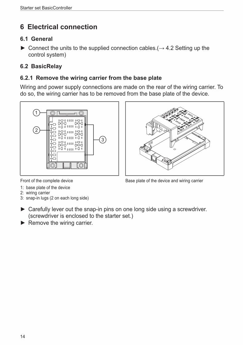
6.2.1 Remove the wiring carrier from the base plateWiring and power supply connections are made on the rear of the wiring carrier� To do so, the wiring carrier has to be removed from the base plate of the device�
Front of the complete device1: base plate of the device2: wiring carrier3: snap-in lugs (2 on each long side)
Base plate of the device and wiring carrier
► Carefully lever out the snap-in pins on one long side using a screwdriver� (screwdriver is enclosed to the starter set�)
► Remove the wiring carrier�
UK
Starter set BasicController
15
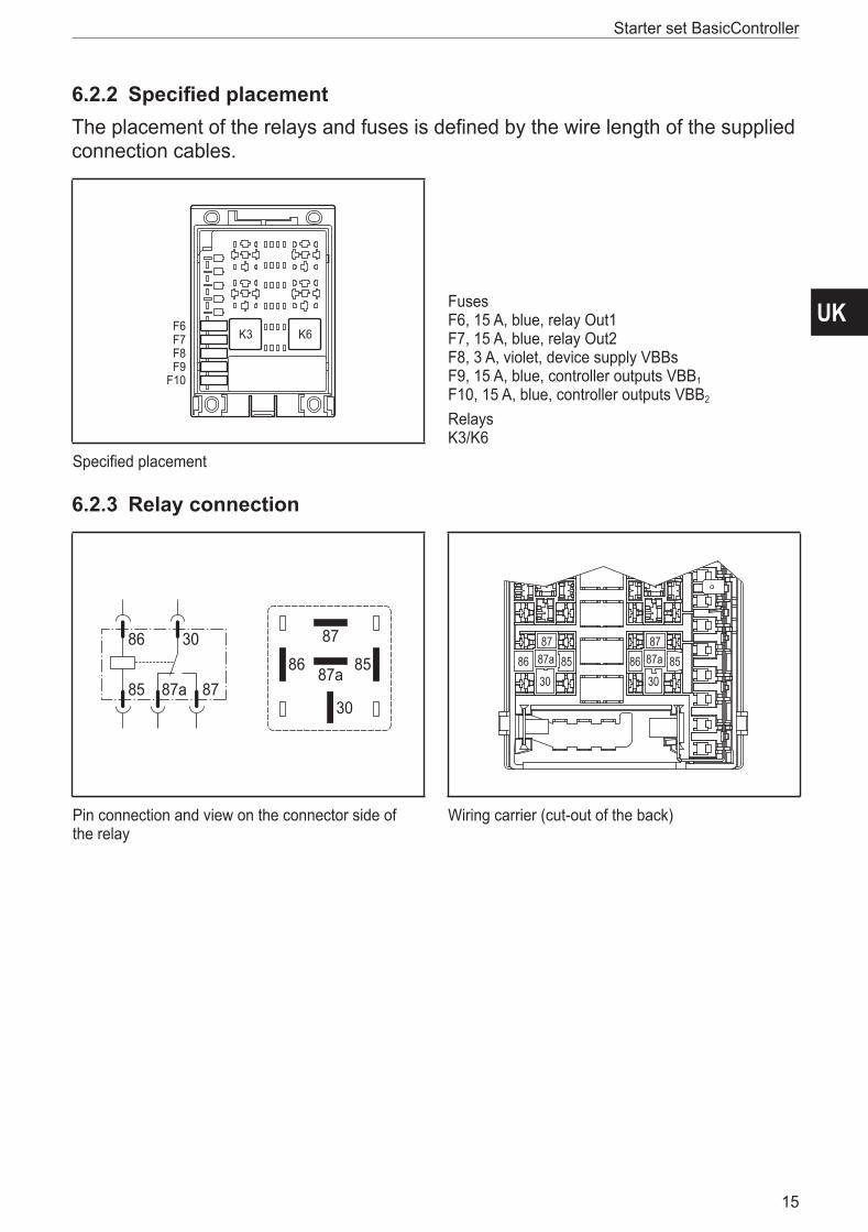
6.2.2 Specified placementThe placement of the relays and fuses is defined by the wire length of the supplied connection cables�
F6F7F8F9
F10
K6K3
FusesF6, 15 A, blue, relay Out1F7, 15 A, blue, relay Out2F8, 3 A, violet, device supply VBBsF9, 15 A, blue, controller outputs VBB1
F10, 15 A, blue, controller outputs VBB2
RelaysK3/K6
Specified placement
6.2.3 Relay connection
87a
87
30
86 8586 30
85 87a 87
858687
30
87a 858687
30
87a
Pin connection and view on the connector side of the relay
Wiring carrier (cut-out of the back)
Starter set BasicController
16
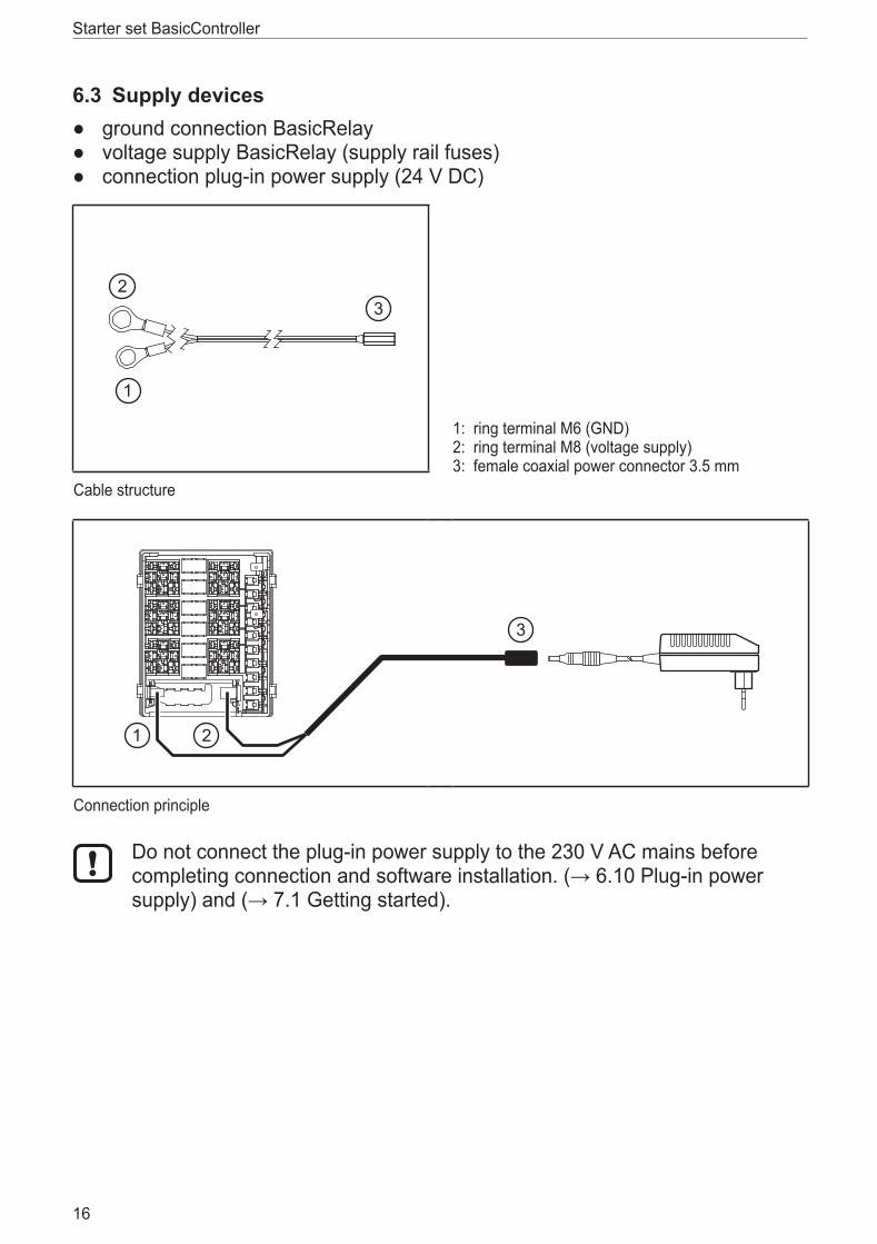
6.3 Supply devices ● ground connection BasicRelay ● voltage supply BasicRelay (supply rail fuses) ● connection plug-in power supply (24 V DC)
1: ring terminal M6 (GND)2: ring terminal M8 (voltage supply)3: female coaxial power connector 3�5 mm
Cable structure
Connection principle
Do not connect the plug-in power supply to the 230 V AC mains before completing connection and software installation. (→ 6.10 Plug-in power supply) and (→ 7.1 Getting started).
UK
Starter set BasicController
17
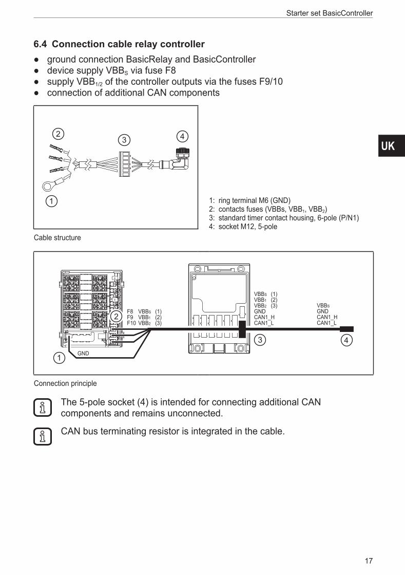
6.4 Connection cable relay controller ● ground connection BasicRelay and BasicController ● device supply VBBS via fuse F8 ● supply VBB1/2 of the controller outputs via the fuses F9/10 ● connection of additional CAN components
1: ring terminal M6 (GND)2: contacts fuses (VBBs, VBB1, VBB2)3: standard timer contact housing, 6-pole (P/N1)4: socket M12, 5-pole
Cable structure
VBBSGNDCAN1_HCAN1_L
VBBSVBB1VBB2GNDCAN1_HCAN1_L
GND
F8F9F10
VBBSVBB1VBB2
(1)(2)(3)
(1)(2)(3)
Connection principle
The 5-pole socket (4) is intended for connecting additional CAN components and remains unconnected�
CAN bus terminating resistor is integrated in the cable�
Starter set BasicController
18
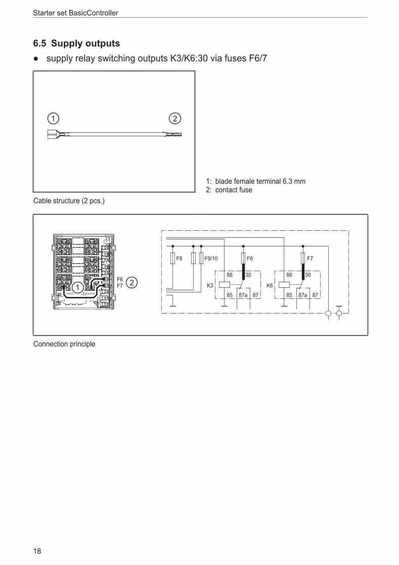
6.5 Supply outputs ● supply relay switching outputs K3/K6:30 via fuses F6/7
1: blade female terminal 6�3 mm2: contact fuse
Cable structure (2 pcs�)
K3
86 30
85 87a 87
K6
86 30
85 87a 87
F8 F9/10 F6 F7
F6F7
Connection principle
UK
Starter set BasicController
19
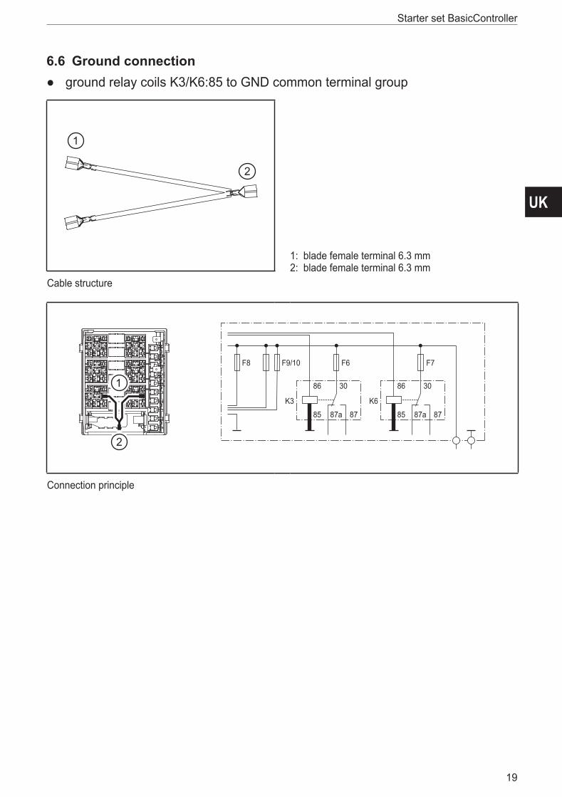
6.6 Ground connection ● ground relay coils K3/K6:85 to GND common terminal group
1: blade female terminal 6�3 mm2: blade female terminal 6�3 mm
Cable structure
K3
86 30
85 87a 87
K6
86 30
85 87a 87
F8 F9/10 F6 F7
Connection principle
Starter set BasicController
20
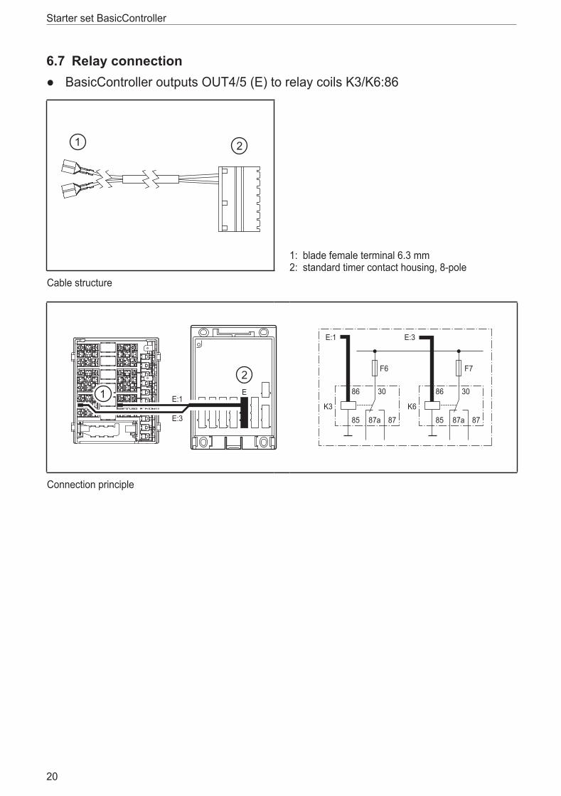
6.7 Relay connection ● BasicController outputs OUT4/5 (E) to relay coils K3/K6:86
1: blade female terminal 6�3 mm2: standard timer contact housing, 8-pole
Cable structure
E
K3
86 30
85 87a 87
K6
86 30
85 87a 87
F6 F7
E:1
E:3
E:1 E:3
Connection principle
UK
Starter set BasicController
21
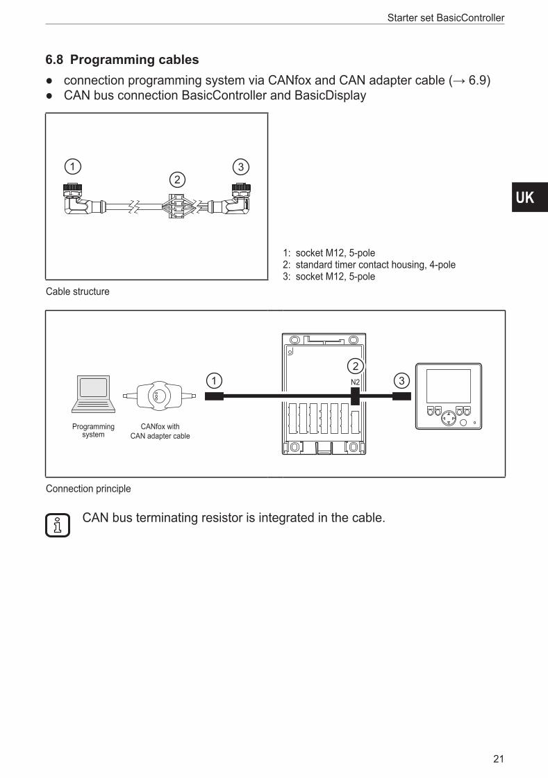
6.8 Programming cables ● connection programming system via CANfox and CAN adapter cable (→ 6.9) ● CAN bus connection BasicController and BasicDisplay
1: socket M12, 5-pole2: standard timer contact housing, 4-pole3: socket M12, 5-pole
Cable structure
N2
Programmingsystem
CANfox with CAN adapter cable
Connection principle
CAN bus terminating resistor is integrated in the cable�
Starter set BasicController
22
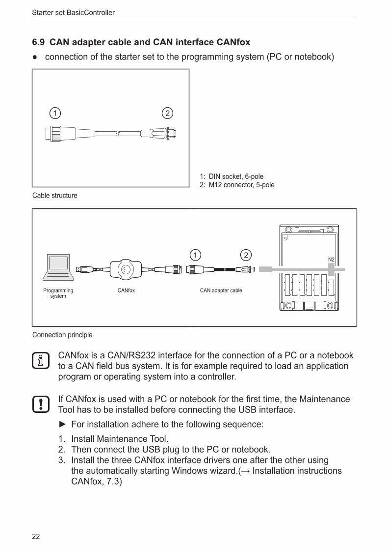
6.9 CAN adapter cable and CAN interface CANfox ● connection of the starter set to the programming system (PC or notebook)
1: DIN socket, 6-pole2: M12 connector, 5-pole
Cable structure
N2
Programmingsystem
CANfox CAN adapter cable
Connection principle
CANfox is a CAN/RS232 interface for the connection of a PC or a notebook to a CAN field bus system� It is for example required to load an application program or operating system into a controller�
If CANfox is used with a PC or notebook for the first time, the Maintenance Tool has to be installed before connecting the USB interface�
► For installation adhere to the following sequence:1� Install Maintenance Tool�2� Then connect the USB plug to the PC or notebook�3� Install the three CANfox interface drivers one after the other using
the automatically starting Windows wizard.(→ Installation instructions CANfox, 7�3)
UK
Starter set BasicController
23
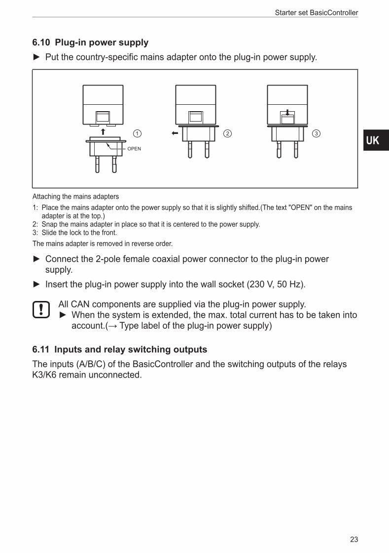
6.10 Plug-in power supply ► Put the country-specific mains adapter onto the plug-in power supply�
OPEN
Attaching the mains adapters1: Place the mains adapter onto the power supply so that it is slightly shifted�(The text "OPEN" on the mains
adapter is at the top�)2: Snap the mains adapter in place so that it is centered to the power supply�3: Slide the lock to the front�The mains adapter is removed in reverse order�
► Connect the 2-pole female coaxial power connector to the plug-in power supply�
► Insert the plug-in power supply into the wall socket (230 V, 50 Hz)�
All CAN components are supplied via the plug-in power supply� ► When the system is extended, the max� total current has to be taken into account.(→ Type label of the plug-in power supply)
6.11 Inputs and relay switching outputsThe inputs (A/B/C) of the BasicController and the switching outputs of the relays K3/K6 remain unconnected�
Starter set BasicController
24
7 Set-up7.1 Getting started
7.1.1 Structure of the preinstalled control system
At the factory a demo program was installed on the units of the starter sets� After power on the BasicController and the BasicDisplay of the starter set are in the "Run" mode�The inputs are switched on and the switching states are visualised via the BasicDisplay and the application program�
1� Take the BasicRelay wiring carrier out of the base plate (→ 6.2.1).2� Connect the prewired connection cables to the units (→ 6.1).3� Insert the fuses and relays into the BasicRelay�4� Connect the plug-in power supply (→ 6.10).
7.1.2 Download your own applications1� Install Maintenance Tool and CoDeSys to the PC/notebook (→ 7.4).2� Connect the starter set to the PC/notebook via CANfox and the CAN adapter
cable (→ 6.9)3� For the connection of additional CAN components set the baud rate of all
devices to 250 Kbits/s or 125 Kbits/s using the Maintenance Tool�4� Load an application into the controller or the display using CoDeSys�
7.2 ProgrammingThe user creates the application software by means of the IEC 61131-3 compliant programming system CoDeSys 2�3�
WARNINGThe user is responsible for the safe function of the application programs which he created himself� If necessary, he must additionally carry out an approval test by corresponding supervisory and test organisations according to the national regulations�
7.3 Required documentationIn addition to the CoDeSys programming system, the following documents are required for programming and set-up of the devices:
● programming manual CoDeSys V2�3 (alternatively as online help)
● system manuals BasicController and BasicDisplay (alternatively as online help)
The manuals are part of the supplied ecomatmobile DVD�
UK
Starter set BasicController
25
7.4 Overview software
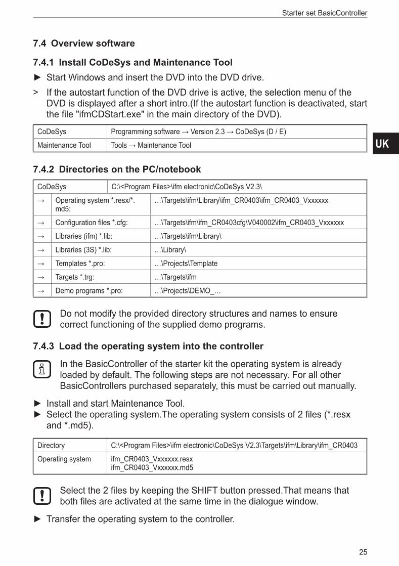
7.4.1 Install CoDeSys and Maintenance Tool ► Start Windows and insert the DVD into the DVD drive�
> If the autostart function of the DVD drive is active, the selection menu of the DVD is displayed after a short intro�(If the autostart function is deactivated, start the file "ifmCDStart�exe" in the main directory of the DVD)�
CoDeSys Programming software → Version 2.3 → CoDeSys (D / E)
Maintenance Tool Tools → Maintenance Tool
7.4.2 Directories on the PC/notebook
CoDeSys C:\<Program Files>\ifm electronic\CoDeSys V2�3\
→ Operating system *�resx/*�md5:
…\Targets\ifm\Library\ifm_CR0403\ifm_CR0403_Vxxxxxx
→ Configuration files *�cfg: …\Targets\ifm\ifm_CR0403cfg\V040002\ifm_CR0403_Vxxxxxx
→ Libraries (ifm) *�lib: …\Targets\ifm\Library\
→ Libraries (3S) *�lib: …\Library\
→ Templates *�pro: …\Projects\Template
→ Targets *�trg: …\Targets\ifm
→ Demo programs *�pro: …\Projects\DEMO_…
Do not modify the provided directory structures and names to ensure correct functioning of the supplied demo programs�
7.4.3 Load the operating system into the controller
In the BasicController of the starter kit the operating system is already loaded by default� The following steps are not necessary� For all other BasicControllers purchased separately, this must be carried out manually�
► Install and start Maintenance Tool� ► Select the operating system�The operating system consists of 2 files (*�resx and *�md5)�
Directory C:\<Program Files>\ifm electronic\CoDeSys V2�3\Targets\ifm\Library\ifm_CR0403
Operating system ifm_CR0403_Vxxxxxx�resx ifm_CR0403_Vxxxxxx�md5
Select the 2 files by keeping the SHIFT button pressed�That means that both files are activated at the same time in the dialogue window�
► Transfer the operating system to the controller�
Starter set BasicController
26
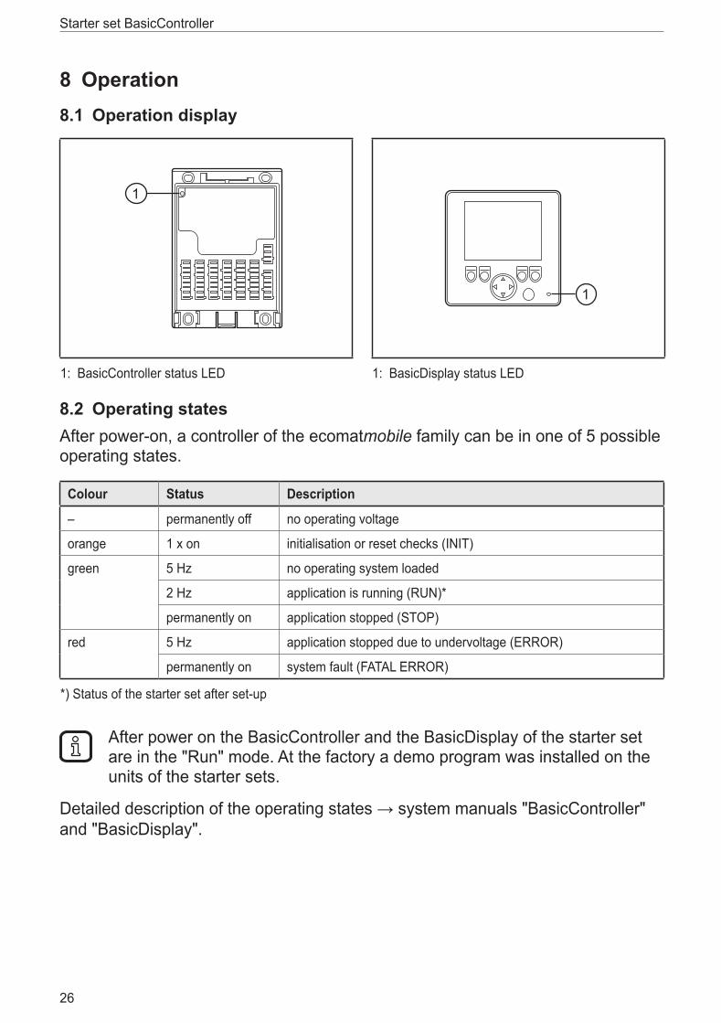
8 Operation8.1 Operation display
1: BasicController status LED 1: BasicDisplay status LED
8.2 Operating statesAfter power-on, a controller of the ecomatmobile family can be in one of 5 possible operating states�
Colour Status Description
– permanently off no operating voltage
orange 1 x on initialisation or reset checks (INIT)
green 5 Hz no operating system loaded
2 Hz application is running (RUN)*
permanently on application stopped (STOP)
red 5 Hz application stopped due to undervoltage (ERROR)
permanently on system fault (FATAL ERROR)
*) Status of the starter set after set-up
After power on the BasicController and the BasicDisplay of the starter set are in the "Run" mode� At the factory a demo program was installed on the units of the starter sets�
Detailed description of the operating states → system manuals "BasicController" and "BasicDisplay"�
UK
Starter set BasicController
27
9 Technical dataThe technical data are part of the respective installation instructions�The supplied mini CD's contain the installation instructions of the Basic components (→ 2.3 Software and documentation).
9.1 Additional informationFor application and product examples from the different areas of mobile control technology please refer to our websites�www.ifm.com → Products → Control systemsFurther documents such as the CE declaration of conformity or the e1 test certificate by the Kraftfahrt-Bundesamt (German Federal Office for Motor Traffic) can be downloaded in PDF format:www.ifm.com → data sheet search → CR0403 → Additional data