brochura dos links pdh stratex - ecli_dasht_etsi_052405
DESCRIPTION
Brochura Dos Links PDH Stratex - Ecli_dasht_ETSI_052405TRANSCRIPT

Switch to Eclipse. Save Today. Save Tomorrow. Eclipse ETSI Datasheet

Switch to Eclipse. Save Today. Save Tomorrow. Eclipse ETSI Datasheet Switch to Eclipse. Save Today. Save Tomorrow. Eclipse ETSI Datasheet
Eclipse Nodal Wireless SolutionEclipse combines all point-to-point wireless applications into a single product platform to dramatically reduce the total cost of using wireless backhaul by changing the way networks are planned, deployed and maintained.
A highly scalable, software-configurable architecture gives operators total control over their networks so they can adapt to changing conditions and anticipate future needs.
Smooth capacity migration with minimal upgrade cost and service disruption enables operators to pay only for the capacity they need, and then increase network capacity in the future when it is required.
Eclipse incorporates the latest technology to deliver a solution optimized to provide wireless connectivity for enterprise, broadband fixed wireless access and mobile backhaul networks.
A Perfect Alignment of FeaturesEclipse is the only product available that provides a unique combination of breakthrough features to help you save today and tomorrow:
• Scalable Super-PDH capacity architecture.
• Optimized wireless node solution.
• Liquid Bandwidth Ethernet transport.
• Single platform for PDH and SDH applications.
• Modular design for easy upgrade and maintenance.

Switch to Eclipse. Save Today. Save Tomorrow. Eclipse ETSI Datasheet Switch to Eclipse. Save Today. Save Tomorrow. Eclipse ETSI Datasheet
Eclipse Super-PDH NetworkingEclipse Super-PDH™ networking provides a perfect alternative to upgrading wireless links to SDH, simply for more capacity.
Super-PDH provides smooth, incremental capacity migration from 4x E1 up to 75x E1 over the same radio path, with selectable modulation and channel bandwidth.
Eclipse Super-PDH provides 20% more E1s than an STM1 link, and without the higher cost and network complexity.
Like SDH, the Eclipse Nodal architecture allows traffic aggregation nodes and self-healing ring networks.
Traffic add and drop and fast traffic protection are built-in, without the need for external multiplexers, patch panels and cables.
Liquid Bandwidth Ethernet TransportEclipse ‘Liquid Bandwidth’ is the most flexible solution available for the transport of Ethernet plus TDM traffic, with configurable bandwidth assignment up to 155 Mbps.
• Ethernet data plus TDM voice transport over a single radio channel.
• Liquid assignment of radio bandwidth between 4 and 75x E1.
• A built-in, 4-port switch with Layer 2 operation.
• Service differentiation through user-configurable VLAN and QoS features.
• Early warning capacity alerts.
• Removes costly external multiplexers and router equipment from the network.
• Seamlessly integrates into Eclipse Super-PDH networks.
Switch to Eclipse. Save Today. Save Tomorrow. Eclipse ETSI Datasheet Switch to Eclipse. Save Today. Save Tomorrow. Eclipse ETSI Datasheet
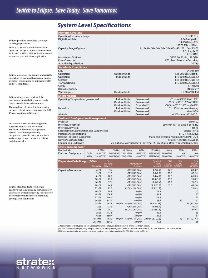
Platform CoverageOperating Frequency Range 5 to 38 GHzDigital Line Rate 2.048 Mbps (E1)
34.368 Mbps (E3)155.52 Mbps (STM1)
Capacity Range Options 4x, 5x, 8x, 10x, 16x, 20x, 32x, 40x, 48x, 52x, 64x, 75xE11, 2, 3, 4, 8x E3
1, 2x STM1Modulation Options QPSK, 16, 32, 64, 128 QAMError Correction FEC, Reed Solomon DecodingAdaptive Equalization 20 Tap
System Level Specifications
Standards ComplianceEMC EN 301 489Operation Outdoor Units ETS 300 019, Class 4.1Operation Indoor Units ETS 300 019, Class 3.2Storage ETS 300 019, Class 1.2Transportation ETS 300 019, Class 2.3Safety EN 60950Radio Frequency EN 302 217Water Ingress Outdoor Units IEC 60529 (IPX6)
EnvironmentalOperating Temperature, guaranteed Indoor Units Guaranteed -5° to +45° C (23 to 113° F)
Outdoor Units Guaranteed -33° to +55° C (-27 to 131° F)Outdoor Units Extended (1) -50° to +65° C (-58° to +149° F)
Humidity Indoor Units Guaranteed 0 to 95%, non-condensingOutdoor Units Guaranteed 0 to 100%
Altitude Guaranteed 4,500 meters (15,000 ft)
Fault and Configuration ManagementProtocol SNMP v2Interface, electrical Ethernet 10/100 Base-T or RS232Interface, physical RJ-45Local/remote Configuration and Support Tool Eclipse Portal Performance Monitoring To ITU-T Rec. G.826Routing Protocols supported Static and dynamic routing, RIP I, RIP II, OSPFNetwork Management Stratex Networks ProVisionEngineering Orderwire Via optional VoIP handset or external RS-422 Digital Orderwire Unit (eg: Ardax)
Emission DesignatorBandwidth 3. 5MHz 7MHz 13.75MHz 14MHz 27.5MHz 28MHz 55MHz 56MHz
Emission Designator QPSK 3M50G7W 7M00G7W 13M75G7W 14M0G7W 27M5G7W 28M0G7W N/A N/AQAM 3M50D7W 7M00D7W 13M75D7W 14M0D7W 27M5D7W 28M0D7W 55M0D7W 56M0D7W
Eclipse provides complete coverage in a single platform.
From 5 to 38 GHz, modulations from QPSK to 128 QAM, and capacities from 4x E1 to 2x STM1, Eclipse has it covered, whatever your wireless application.
Eclipse gives you the secure and reliable operation in licensed frequency bands, with full compliance to applicable ETSI and ITU standards.
Eclipse designs are hardened for maximum survivability in extremely tough installation environments.
Thorough accelerated lifetime testing ensures reliable operation over the full 15-year equipment lifetime.
Java-based Portal local management software and Stratex Networks’ ProVision V Element Management system have been specifically designed to provide exceptional fault and configuration control for Eclipse nodal networks.
Dispersive Fade Margin (DFM) GrossBit RateMbps [2]
Modulation Options
Symbol Rate,
Mbaud
DFM RAC10/
ODU100
DFM RAC40/
ODU300
DFM RAC 30/
ODU300Capacity
Capacity/Modulation 4xE1 9.4 QPSK (16 QAM) 4.7 (2.4) 74.5 88 (87)5xE1 11.5 QPSK (16 QAM) 5.8 (2.9) 73.5 86 (91)8xE1 18.8 QPSK (16 QAM) 9.4 (4.7) 71.5 80 (85)
10xE1 22.8 QPSK (16 QAM) 11.4 (5.7) 70.5 78 (82)16xE1 37.6 QPSK (16 QAM) 18.8 (9.4) 68.5 71 (75)20xE1 44.9 QPSK (16 QAM) 22.5 (11.2) 67.5 68 (74)32xE1 75.2 16 QAM (64 QAM) 18.8 (11.9) 72 (63)40xE1 88.9 16 QAM 22.2 6348xE1 106.8 32 QAM 21.4 5752xE1 116.6 32 QAM 23.3 5564xE1 142.4 64 QAM 23.7 50 5175xE1 167.8 128 QAM (16 QAM / 64 QAM) 24 (42 / 28) 50 (49 / 44)
1xE3 37.6 QPSK (16 QAM) 18.8 (9.4) 71 (75)2xE3 75.2 16 QAM (64 QAM) 18.8 (12.5) 67 (61)3xE3 112.8 32 QAM 22.6 554xE3 150.4 128 QAM 21.5 51
1xSTM1 167.0 128 QAM (16 QAM / 64 QAM) 23.9 (41.8 / 27.8) 43 51 (50 / 44)2xSTM1 334.0 128 QAM 47.8 36
All specifications are typical values unless otherwise stated, and are subject to change without notice.[1] Over full extended operating temperature Eclipse may be subject to reduced performance. Contact Stratex Networks for more details.[2] Gross bit rate includes usable customer payload plus radio overhead for FEC, NMS, AUX traffic, etc.
Eclipse standard features include adaptive equalization and forward error correction with interleaving for superior performance in the most demanding propagation conditions.

Switch to Eclipse. Save Today. Save Tomorrow. Eclipse ETSI Datasheet Switch to Eclipse. Save Today. Save Tomorrow. Eclipse ETSI Datasheet
Platform Configuration OptionsTerminal One radio path IDU & ODU100
One radio path INU or INUe & ODU100/ODU300Node, Repeater Two radio paths INU & ODU100/ODU300
Two radio paths INUe & ODU100/ODU300Node, Ring Two radio paths INU or INUe & ODU100/ODU300Node, Aggregation Up to three radio paths INU & ODU100/ODU300
Up to six radio paths INUe & ODU100/ODU300
Eclipse ConfigurationsWireless Network NodesEclipse is the first wireless platform to optimize wireless networks by support-ing multiple ODUs and built-in traffic routing to eliminate external equipment and cabling.
Eclipse ConfigurationsEquipment redundancy and diversity options are available to protect valuable traffic against equipment failure or radio path impairments. Eclipse also supports co-channel dual-polar (CCDP) operation with cross-pole interference cancellation (XPIC).
Eclipse Optimised Wireless NodesThe Eclipse Intelligent Node Unit (INU) enables complex wireless nodes or simple terminal configurations in a highly modular design.
Eclipse nodes can support up to six outdoor units (ODUs) with traffic routing between radio paths and local interfaces without external cabling or patch panels. Traffic add-and-drop, north-south traffic aggregation and concentration, and hardware, ring and diversity path protection switching are all built in.
The INU incorporates a capacity-independent design, and can be software configured for Nx E1, Nx E3 or Nx STM1 operation.
Hot swappable plug-in cards provide radio (ODU) traffic and auxiliary interfaces. Cards can be added or replaced to add new radio paths, for equipment protection, or for rapid maintenance.
This modular approach, combined with efficient designs, lower parts count and fewer points of failure, results in higher nodal reliability compared to using multiple indoor units (IDUs).
Optional Data Access Cards provide user selection of traffic interface densities and types between E1, E3, STM1 and 10/100 Base-T Ethernet.
Radio Path Protection OptionsNon Protected, 1+0 5 - 38 GHzProtected Hot Standby, 1+1 5 - 38 GHzSpace Diversity, 1+1 5 - 15 GHzFrequency Diversity, 1+1 XPIC Optional 5 - 15 GHzDual Path, Non-Protected, 2+0 XPIC Optional 5 - 23 GHzDual Path, Protected, 2+2 XPIC Optional 5 - 23 GHz
All specifications are typical values unless otherwise stated, and are subject to change without notice.
Switch to Eclipse. Save Today. Save Tomorrow. Eclipse ETSI Datasheet Switch to Eclipse. Save Today. Save Tomorrow. Eclipse ETSI Datasheet
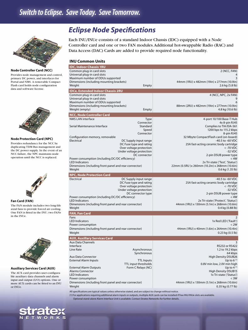
Eclipse Node SpecificationsEach INU/INUe consists of a standard Indoor Chassis (IDC) equipped with a Node Controller card and one or two FAN modules. Additional hot-swappable Radio (RAC) and Data Access (DAC) Cards are added to provide required node functionality.
Node Controller Card (NCC)Provides node management and control, primary DC power, and interfaces for Portal and NMS. A removable Compact Flash card holds node configuration data and software license.
Node Protection Card (NPC)Provides redundancy for the NCC by duplicating TDM Bus management and the DC power supply. In the event of an NCC failure, the NPC maintains node operation until the NCC is replaced.
Fan Card (FAN)The FAN module includes two long-life axial fans to provide forced air cooling. One FAN is fitted in the INU; two FANs in the INUe.
Auxiliary Services Card (AUX)The AUX card provides user-configura-ble auxiliary data channels and alarm input and output (I/O) options. One or more AUX cards can be fitted to an INU or INUe.
INU Common UnitsIDC, Indoor Chassis 1RUCommon plug-in card slots 2 (NCC, FAN)Universal plug-in card slots 4Maximum number of ODUs supported 3Dimensions (including mounting brackets) 44mm (1RU) x 482mm (19in) x 277mm (10.9in)Weight Empty 2.6 kg (5.8 lb)
IDCe, Extended Indoor Chassis 2RUCommon plug-in card slots 4 (NCC, NPC, 2x FAN)Universal plug-in card slots 9Maximum number of ODUs supported 6Dimensions (including mounting brackets) 88mm (2RU) x 482mm (19in) x 277mm (10.9in)Weight (empty) Empty 4.8 kg (10.6 lb)
NCC, Node Controller CardNMS LAN interface Type 4-port 10/100 Base-T Hub
Connector 4x 8-pin RJ45Serial Maintenance Interface Standard Complies to TIA/EIA-561
Speed 1200 bps to 115.2 kbpsConnector 8-pin RJ45
Configuration memory, removable 32 Mbyte CompactFlash card (on-board)Electrical DC Supply input range -40.5 to -60 VDC
DC Fuse type and rating 25A fast-acting ceramic body cartridgeOver voltage protection < -70 VDC
Under voltage protection -32 VDCDC connector 2-pin DSUB power type
Power consumption (including DC/DC efficiency) < 4WLED Indicators 2x Tri-state ('Test', 'Status')Dimensions (including front panel and rear connector) 22mm (0.5RU )x 260mm (10.2in) x 268mm (10.6in)Weight 0.6 kg (1.35 lb)
NPC, Node Protection CardElectrical DC Supply input range -40.5 to -60 VDC
DC Fuse type and rating 25A fast-acting ceramic body cartridgeOver voltage protection < -70 VDC
Under voltage protection -32 VDCDC connector type 2-pin DSUB power type
Power consumption (including DC/DC efficiency) < 4WLED Indicators 2x Tri-state ('Protect', 'Status')Dimensions (including front panel and rear connector) 44mm (1RU) x 130mm (5.1in) x 268mm (10.6in)Weight 0.4 kg (0.88 lb)
FAN, Fan CardFans 2LED Indicators 1x Red LED ('Fault')Power consumption < 2WDimensions (including front panel and rear connector) 44mm (1RU) x 40mm (1.6in) x 264mm (10.4in)Weight 0.23 kg (0.5 lb)
AUX, Auxillary Services CardAux Data Channels 3Interface RS232 or RS422Line Rate Asynchronous 1.2 to 19.2 kbps
Synchronous 64 kbpsAux Data Connector High Density DSUB26 External Alarm Inputs TTL Inputs Up to 6 (1)
TTL input thresholds 0.8V min low, 2.0V min highExternal Alarm Outputs Form C Relays (NC) Up to 4 (1)
Alarms Connector High Density DSUB15 LED Indicators 1x Tri-state ('Status')Power consumption < 3WDimensions (including front panel and rear connector) 44mm (1RU) x 130mm (5.1in) x 268mm (10.6in)Weight 0.35 kg (0.77 lb)
All specifications are typical values unless otherwise stated, and are subject to change without notice.
[1] For applications requiring additional alarm inputs or outputs, multiple AUX cards can be installed if free INU/INUe slots are available.
Optional stand-alone Alarm Interface Unit is available. Contact Stratex Networks for further details.

Switch to Eclipse. Save Today. Save Tomorrow. Eclipse ETSI Datasheet Switch to Eclipse. Save Today. Save Tomorrow. Eclipse ETSI Datasheet
Radio Access CardsGeneralIF connector SMA[1]
LED Indicators 2x Tri-state (‘Online’, ‘Status’)Dimensions (including front panel and rear connector) 44mm (1RU) x 130mm (5.1in) x 268mm (10.6in)Weight < 0.38 kg (0.84 lb)Secondary Lightning protection Gas tube, 150V
RAC 10ODUs supported ODU100Capacities supported 4x, 5x, 8x, 10x, 16x, 20x E1Modulations supported QPSKIF interface Transmit 320 MHz, -2.0 to -7.0 dBm
Receive 126 MHz, -2 to -22 dBmPower consumption < 6.5W
RAC 30ODUs supported ODU300Capacities supported 4-75x E1, 1-4x E3, 1x STM1Modulations supported QPSK, 16, 32, 64, 128QAMIF interface Transmit 311 MHz, -8.0 to -12.0 dBm
Receive 126 MHz, -8 to -27 dBmPower consumption 8W
RAC 3X, (>30MBaud)ODUs supported ODU300Capacities supported 5-8x E3, 1-2x STM1Modulations supported 16, 64, 128QAMIF interface Transmit 311 MHz, -8.0 to -12.0 dBm
Receive 126 MHz, -8 to -27 dBmPower consumption < 6.5W
RAC 40 with XPICODUs supported ODU300Capacities supported 64, 75x E1, 1x STM1Modulations supported 64, 128QAMXPD Improvement 20 dBIF interface Transmit 311 MHz, -8.0 to -12.0 dBm
Receive 126 MHz, -8 to -27 dBmXPIC connectors 2x SMBPower consumption 12W
All specifications are typical values unless otherwise stated, and are subject to change without notice.
[1] RAC Installation Kit includes 3-meter jumper cable, SMA to N-type.
Radio Access Card (RAC) The RAC provides the interface and signal processing between the TDM Bus and an ODU. Functions include modulation/demodulation, FEC, adaptive equalization, IF conversion, IF loopback and automatic protection switching for hot standby, diversity and ring configurations.
RAC 40Supports the ODU300, for capacities up to 64x E1 and 1x STM1, using band-widths up to 30 MHz and modulations to 128 QAM. Two RAC 40s installed in the same or co-located INU/INUe’s enable co-channel operation with cross-pole interference cancellation (XPIC).
RAC 3XSupports the ODU300, for capacities up to 2x STM1 Mbps and 8x E3, using bandwidths greater than 30 MHz and modulations up to 128 QAM.
RAC 30Supports the ODU300, for capacities up to 75x E1, 3x E3 or 1x STM1, using band-widths up to 30 MHz and modulations from QPSK to 128 QAM.
RAC 10Supports the ODU100, for capacities up to 20x E1, using bandwidths up to 30 MHz and QPSK modulation.
Switch to Eclipse. Save Today. Save Tomorrow. Eclipse ETSI Datasheet Switch to Eclipse. Save Today. Save Tomorrow. Eclipse ETSI Datasheet
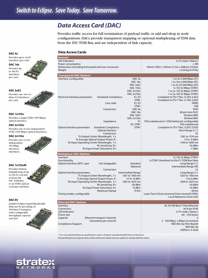
Data Access Cards
GeneralLED Indicators 1x Tri-state (‘Status’)Power consumption < 3WDimensions (including front panel and rear connector) 44mm (1RU) x 130mm (5.1in) x 268mm (10.6in)Weight < 0.34 kg (0.74 lb)
Transparent DAC OptionsInterface, configurable DAC 4x 1 to 4x 2.048 Mbps (E1)
DAC 16x 1 to 16x 2.048 Mbps (E1)DAC 3xE3 1 to 3x 34.368 Mbps (E3)DAC 155o 1x 155.52 Mbps (STM1)
DAC 2x155o 1 or 2x 155.52 Mbps (STM1)DAC 2x155e 1 or 2x 155.52 Mbps (STM1)
Electrical interface parameters Standards Compliance E1, E3 Compliant to ITU-T Rec. G.703, G.823STM1 Compliant to ITU-T Rec. G.703, G.825
Line code E1, E3 HDB3STM1 CMI
Connectors DAC 4x RJ45DAC 16x 48 pin mini-RJ21
DAC 3xE3 Slimline BNCDAC 2x155e Slimline BNC
Impedance E1 75Ω unbalanced or 120Ω balanced, configurableE3, STM1 75Ω unbalanced
Optical interface parameters Standards Compliance STM1 Compliant to ITU-T Rec. G.957, G.825Optical interface Short Range S-1.1
Connectors SC Tx Output Center Wavelength, λc 1261 to 1310 nm
Tx Average Optical Output Power, Po -15 to -8 dBmRx Input Operating Center Wavelength, λc 1100 to 1600 nm
Rx Sensitivity, Pin -34 dBmRx Input Power Saturation, Pin -7 dBm
Multiplexer DAC OptionsInterface 1x 155.52 Mbps (STM1)Functionality 1x STM1 (Interface) to 63x E1 (TDM Bus) MuxOptical interface (SFP), type Hot Swappable Standard Long Range L1.1
Optional Intermediate Range (IR)Connectors LC
Optical interface parameters Intermediate Range Long Range L1.1Tx Output Center Wavelength, λc 1261 to 1360 nm 1263 to 1360 nm
Tx Average Optical Output Power, Po -15 to -8 dBm -5 to 0 dBmRx Input Operating Center Wavelength, λc 1265 to 1625 nm 1266 to 1625 nm
Rx Sensitivity, Pin -28 dBm -34 dBmRx Input Power Saturation, Pin -8 dBm -10 dBm
Maximum Range 15 km 40 kmTiming modes, configurable Loop Time (Clock recovered from received STM1)
Local Reference Clock (XO)
Ethernet DAC Options Interface 4x 10/100 Base-T Fast EthernetConnectors 4x 8-pin RJ45LED Indicators 1x Tri-state (‘Status’)Frame size 64 - 1532 bytesCapacity Ethernet transport channels 2
Granularity per channel 2 - 100 Mbps, 2 Mbps incrementsCompliance/Support IEEE 802.3q (Port Based)
IEEE 802.3pDiffServ, 4-level
* For more detailed Ethernet specifications refer to Eclipse Liquid Bandwidth Ethernet Brochure.
All specifications are typical values unless otherwise stated, and are subject to change without notice.
Data Access Card (DAC)Provides traffic access for full termination of payload traffic or add and drop in node configurations. DACs provide transparent mapping or optional multiplexing of TDM data from the INU TDM Bus, and are independent of link capacity.
DAC 4xProvides up to 4x E1 interfaces per card.
DAC 16xProvides up to 16x E1 interfaces per card.
DAC 1x155oMProvides built-in multiplexing of up to 63x E1 circuits to/from the INU TDM Bus to an STM1 optical customer interface.
DAC 1x155oProvides a single STM1 (155 Mbps) optical interface.
DAC 2x155oProvides one or two independent STM1 (155 Mbps) optical interfaces.
DAC 2x155eProvides one or two independent 155 Mbps electrical interfaces.
DAC ESEnables Eclipse Liquid Bandwidth Ethernet by providing 2x 100 Base-T transport, with configurable throughput capacity and QoS.
DAC 3xE3Provides one, two or three E3 interfaces per card.

Switch to Eclipse. Save Today. Save Tomorrow. Eclipse ETSI Datasheet Switch to Eclipse. Save Today. Save Tomorrow. Eclipse ETSI Datasheet
Eclipse Terminal, Indoor Units (IDU)Eclipse Indoor Units provide a simple and economical 1RU solution for terminal configurations, where support for only one radio path is required. IDUs provide software capacity selection, and are designed to be over-the-air compatible with the Eclipse INU/INUe.
GeneralConfiguration memory, removable 32 Mbyte CompactFlash card (rear access)LED Indicators 2x Tri-state LEDs (‘IDU Status’, ‘ODU Status’)Line Interface Standards Compliance Compliant to ITU-T Rec. G.703, G.823
Line Code HDB3Impedance 75Ω unbalanced or 120Ω balanced, configurable
IF interface Transmit 320 MHz, -2.0 to -7.0 dBmReceive 126 MHz, -2 to -22 dBm
IF Cable Connector N-TypeProtection Connector IDU 20x only 9 pin D-SUBAuxiliary Data Aux Data Channels 1
Interface RS232 or RS422Line Rate, configurable 1.2 to 19.2 kbps, asynchronous
64 kbps, synchronousConnector type 9 pin D-SUB
Alarm I/O External Alarm Inputs 2 - TTLExternal Alarm Outputs 4 - Form C Relay
Connector type 15 pin D-SUBNMS LAN interface Type 10/100 Base-T Ethernet
Connector 8-pin RJ45Serial Maintenance Interface Standard Complies to TIA/EIA-561
Speed 1200 bps to 115.2 kbpsConnector 8-pin RJ45
Electrical Input Voltage Range -40.5 to -60.0 VDCPower Consumption < 10W
Protection Circuit 3A Slow-Blow FuseMechanical Dimensions 44mm (1RU)x 482mm (19in) x 280mm (11.0in)
Weight 1.6 kg (3.5 lb)
IDU 8xCapacity Options configurable, 4, 5, 8x 2.048 Mbps (E1)Configuration Options Non Protected (1+0) onlyODUs supported ODU100 onlyCompatibility IDU 16x, IDU 20x, INU/INUe/RAC10Traffic Connectors 8x RJ45
IDU 16xCapacity Options configurable, 4, 5, 8x 2.048 Mbps (E1)Configuration Options Non Protected (1+0) onlyODUs supported ODU100 onlyCompatibility IDU 8x, IDU 20x, INU/INUe/RAC10Traffic Connectors 16x RJ45
IDU 20xCapacity Options configurable, 4, 5, 8, 10, 16, 20x 2.048 Mbps (E1)Configuration Options Non Protected (1+0)
Protected Hot Standby (1+1), no diversityODUs supported ODU100 onlyCompatibility IDU 8x, IDU 16x, INU/INUe/RAC10Traffic Connectors 20x RJ45
All specifications are typical values unless otherwise stated, and are subject to change without notice.
IDU 16xNon-protected only IDU that supports ODU100, for link capacities of 4/8/16x E1.
IDU 20xIDU that supports ODU100, for link capacities of 4/5/8/10/16/20x E1. Non-protected or protected with addition of second IDU and interconncting cable.
IDU 8xNon-protected only IDU that supports ODU100, for link capacities of 4/8x E1.

Switch to Eclipse. Save Today. Save Tomorrow. Eclipse ETSI Datasheet Switch to Eclipse. Save Today. Save Tomorrow. Eclipse ETSI Datasheet
ODU100The ODU100 provides scalable capacity support up to 20x E1, in licensed frequency bands from 7 to 38 GHz, in a common mechanical design.
The Eclipse outdoor unit is a fully environmental sealed unit containing one transceiver. It is designed to mount directly to the antenna, and connect to the INU/IDU by a single RG-8 style coaxial cable.
General ODU SpecificationsGeneralODU100 Frequency Range 7, 8, 13, 15, 18, 23, 26, 38 GHz
Capacities [1] 4, 5, 8, 10, 16, 20x E1Modulations QPSK
ODU300 Frequency Range 5, L6, U6, 7, 8, 11, 13, 15, 18, 23 GHzCapacities 4, 5, 8, 10, 16, 20, 32, 40, 48, 52, 64, 75x E1
1, 2, 3, 4, 8x E31 to 2x STM1
Modulations 16, 32, 64, 128 QAMIF SpecificationsIntermediate Frequency ODU100 Transmit 320 MHz
ODU300 Transmit 311 MHzODU100/300 Receive 126 MHz
IF Cable, recommended INU/IDU to ODU Belden 9913 (RG-8) 50ΩMaximum IF Cable length [3] INU/IDU to ODU 300 meters (1,000 ft)ODU InterfacesIF cable connector N-TypeAGC monitor point BNCAntenna port Interface 5 GHz Coax, 7/16 DIN F
6-38 GHz Standard EIA rectangular waveguide, refer to ODU System specificationsPolarisation, field selectable Vertical (standard) or HorizontalAntenna Mounting 5 GHz, standard Remote mount via coax connection
6-38 GHz, standard Proprietary direct mount for antenna diameters 0.3 to 1.8m (1 to 6ft)Remote mount for antenna diameters >1.8m (>6ft)
6-38 GHz, optional Remote mount via flex/elliptical waveguideGeneral Transmitter SpecificationsTransmit Power Tolerance 5 to 26 GHz ± 2 dB
38 GHz ± 3 dBTransmitter Source SynthesizedFrequency Stability ± 10 ppmManual Transmitter Power Control range QPSK ODU100 25 dB
ODU300 30 dB16QAM 26 dB32QAM 25.5 dB64QAM 25 dB
128QAM 24 dBResolution 0.1 dB steps
Accuracy ± 2 dBAutomatic Transmitter Power Control Range Configurable over full available manual attenuation range
Resolution 0.1 dB stepsSpeed 6 dB / sec
Transmitter Mute > 50 dBChannel Selection By software control within tuning range of ODU
(see ODU System Specifications), via Portal or ProVisionSynthesizer Resolution 0.25 MHzGeneral Receiver SpecificationsReceiver Source SynthesizedFrequency Stability ± 10 ppmReceiver Overload BER = 1x10⁻⁶ -22 dBmResidual (Background) Bit Error Rate Better than 10-13
RSSI Accuracy -40 to -70 dBm, 0 to +35oC ODU100 ± 3 dBODU300 ± 2 dB
-25 to -85 dBm, -33 to +55oC ± 4 dBAdditional Protection Losses Frequency Band Main Channel Protection ChannelSplitter option 5 GHz 3.5 dB 3.5 dB
6 to 18 GHz 3.6 dB 3.6 dB21 to 26 GHz 3.8 dB 3.8 dB
38 GHz 4 dB 4 dBCoupler option 5 GHz 1.5 dB 6.4 dB
6 to 18 GHz 1.6 dB 6.6 dB21 to 26 GHz 1.8 dB 6.8 dB
38 GHz 2 dB 7 dBElectricalPower Consumption ODU100 40W max
ODU300 50W maxMechanicalODU100[2] Size (H x W x D) 287mm (11.2 in) x 287mm (11.2 in) x 119mm (4.7 in)
Weight, max 6.0 kg (13.2 lb)ODU300 Size (H x W x D) 287mm (11.2 in) x 287mm (11.2 in) x 162mm (6.4 in)
Weight, max 8.8 kg (19.4 lb)ODU Protection Splitter/Coupler Size (H x W x D) 600mm (23.6 in) x 250mm (9.8 in) x 105mm (4.2 in)(supports all ODUs) Weight 5 to 8GHz: 8.5 kg (18.7 lb)
11 to 38GHz: 6.8 kg (15 lb)[1] 5/10/20xE1 capacity options are available for ODU100 with PNo prefix ECS only.
[2] ODU100 weight and dimensions are for PNo prefix ECS. Prefix EBS ODU100 weight is 7.7kg (16.7ib), ODU depth is 162mm (6.4 in).
[3] Maximum IF cable length is quoted for recommended RG-8 cable. Longer distances are possible using higher specification cable, but performance is not guaranteed by Stratex Networks.
All specifications are typical values unless otherwise stated, and are subject to change without notice.
ODU300The ODU300 is the most flexible ODU available on the market. It provides scalable capacity/modulation support up to 2x STM1/128QAM, in licensed frequency bands from 5 to 23 GHz, in a common mechanical design.

Switch to Eclipse. Save Today. Save Tomorrow. Eclipse ETSI Datasheet Switch to Eclipse. Save Today. Save Tomorrow. Eclipse ETSI Datasheet
ODU System SpecificationsSystem 5 GHz [1] L6 GHz U6 GHz 7 GHz 8 GHz 11 GHz 13 GHz 15 GHz 18 GHz 23 GHz 26 GHz 38 GHz
Frequency Range, GHz 4.4 - 5.0 5.925 - 6.425
6.425 - 7.11 7.125 - 7.9 7.725
- 8.5 10.7 - 11.7 12.75 - 13.25
14.4 - 15.35 17.7 - 19.7 21.2
- 23.63224.52
- 26.48337.0
- 39.46
T-R Spacings supported, MHz 300, 312 252.04 340 154, 161, 245
119, 126, 151.614,
266, 311.32
490, 530 266315, 420, 490, 644,
728
1010, 1092.5
1008, 1200, 1232
1008 1260
Maximum Tuning Range (dependent upon T-R spacing), MHz 56 56 56 56 140 165 84 245 380 370 360 340
Antenna Interface
Waveguide Type N/A R70 (WR137)
R70 (WR137)
R84 (WR112)
R84 (WR112)
R100 (WR90)
R120 (WR75)
R140 (WR62)
R220 (WR42)
R220 (WR42)
R220 (WR42)
R320 (WR28)
Flange Type Coax UDR70 UDR70 UDR84 UDR84 UDR100 UBR120 UBR140 UBR220 UBR220 UBR220 UBR320
Mating Flange Type 7/16 DIN F
PDR70 or CDR70
PDR70 or CDR70
PDR84 or CDR84
PDR84 or CDR84
PDR100 or
CDR100
PBR120 or
CDR120
PBR140 or CBR140 PBR220 PBR220 PBR220 PBR320
System Gain [2]
ODU100 [3] 4xE1 7 MHz QPSK 114.0 dB 114.0 dB 107.0 dB 107.5 dB 106.0 dB 103.5 dB 104.0 dB 101.5 dB5xE1 7 MHz QPSK 113.0 dB 113.0 dB 106.0 dB 106.5 dB 105.0 dB 103.0 dB 103.5 dB 101.0 dB8xE1 13.75 / 14 MHz QPSK 111.5 dB 111.5 dB 104.5 dB 105.0 dB 103.5 dB 101.5 dB 102.0 dB 99.5 dB
10xE1 13.75 / 14 MHz QPSK 111.0 dB 111.0 dB 103.5 dB 104.5 dB 101.5 dB 100.5 dB 101.0 dB 98.5 dB16xE1 27.5 / 28 MHz QPSK 109.0 dB 109.0 dB 101.5 dB 102.5 dB 100.5 dB 98.5 dB 99.0 dB 96.5 dB20xE1 27.5 / 28 MHz QPSK 108.0 dB 108.0 dB 100.5 dB 101.5 dB 99.5 dB 97.5 dB 98.0 dB 95.5 dB
ODU300 4xE1 7 MHz QPSK 123.0 dB 123.0 dB 123.0 dB 123.0 dB 123.0 dB 117.5 dB 120.5 dB 119.0 dB 113.0 dB 112.5 dB5xE1 7 MHz QPSK 122.0 dB 122.0 dB 122.0 dB 122.0 dB 122.0 dB 116.5 dB 119.5 dB 118.0 dB 112.0 dB 112.0 dB8xE1 13.75 / 14 MHz QPSK 120.0 dB 120.0 dB 120.0 dB 120.0 dB 120.0 dB 114.5 dB 117.5 dB 116.0 dB 110.0 dB 110.0 dB
10xE1 13.75 / 14 MHz QPSK 119.0 dB 119.5 dB 119.5 dB 119.5 dB 119.5 dB 113.5 dB 116.5 dB 115.5 dB 109.0 dB 109.0 dB16xE1, 1xE3 27.5 / 28 MHz QPSK 117.0 dB 117.5 dB 117.5 dB 117.5 dB 117.5 dB 111.5 dB 114.5 dB 113.5 dB 107.0 dB 107.0 dB
20xE1 27.5 / 28 MHz QPSK 116.0 dB 116.5 dB 116.5 dB 116.5 dB 116.5 dB 110.5 dB 113.5 dB 112.5 dB 106.0 dB 106.0 dB4xE1 3.5 MHz 16QAM 114.5 dB 115.5 dB 115.5 dB 115.5 dB 115.5 dB 109.0 dB5xE1 3.5 MHz 16QAM 113.5 dB 114.0 dB 114.0 dB 114.0 dB 114.0 dB 108.0 dB8xE1 7 MHz 16QAM 111.5 dB 112.0 dB 112.0 dB 112.0 dB 112.0 dB 106.0 dB 109.0 dB 108.0 dB 102.0 dB 102.0 dB
10xE1 7 MHz 16QAM 111.0 dB 111.0 dB 111.0 dB 111.0 dB 111.0 dB 105.5 dB 108.5 dB 107.0 dB 101.0 dB 100.5 dB16xE1, 1xE3 13.75 / 14 MHz 16 QAM 109.0 dB 109.0 dB 109.0 dB 109.0 dB 109.0 dB 103.5 dB 106.5 dB 105.0 dB 99.0 dB 98.5 dB16xE1, 1xE3 7 MHz 64 QAM 103.5 dB 103.5 dB 103.5 dB 103.5 dB 103.5 dB 98.0 dB 101.0 dB 99.5 dB 93.5 dB 93.0 dB
20xE1 13.75 / 14 MHz 16 QAM 108.0 dB 108.0 dB 108.0 dB 108.0 dB 108.0 dB 102.5 dB 105.5 dB 104.0 dB 98.0 dB 97.5 dB32xE1, 2xE3 27.5 / 28 MHz 16 QAM 106.0 dB 106.0 dB 106.0 dB 106.0 dB 106.0 dB 100.5 dB 103.5 dB 102.0 dB 96.0 dB 95.5 dB32xE1, 2xE3 13.75 / 14 MHz 64 QAM 101.0 dB 101.5 dB 101.5 dB 101.5 dB 101.5 dB 95.0 dB 98.0 dB 96.5 dB 90.5 dB 90.0 dB
40xE1 27.5 / 28 MHz 16 QAM 105.0 dB 105.0 dB 105.0 dB 105.0 dB 105.0 dB 99.5 dB 102.5 dB 101.0 dB 95.0 dB 94.5 dB48xE1, 3xE3 27.5 / 28 MHz 32 QAM 102.5 dB 103.0 dB 103.0 dB 103.0 dB 103.0 dB 96.0 dB 99.0 dB 98.0 dB 91.5 dB 91.5 dB
52xE1 27.5 / 28 MHz 32 QAM 101.0 dB 101.5 dB 101.5 dB 101.5 dB 101.5 dB 95.5 dB 98.5 dB 97.5 dB 91.0 dB 91.0 dB64xE1 27.5 / 28 MHz 64 QAM 97.5 dB 97.5 dB 97.5 dB 97.5 dB 97.5 dB 92.0 dB 95.0 dB 93.5 dB 87.5 dB 87.0 dB
75xE1, 4xE3, 1xSTM1[4] 55 / 56 MHz 16 QAM 91.0 dB 91.0 dB75xE1, 4xE3, 1xSTM1[4] 40 MHz 64 QAM 97.0 dB 97.0 dB 91.5 dB75xE1, 4xE3, 1xSTM1 27.5 / 28 MHz 128 QAM 93.5 dB 94.0 dB 94.0 dB 94.0 dB 94.0 dB 88.0 dB 91.0 dB 90.0 dB 83.5 dB 83.5 dB
8xE3, 2xSTM1[4) 55 / 56 MHz 128 QAM 82.0 dB 81.5 dB
All specifications are typical values unless otherwise stated, and are subject to change without notice.
For Guaranteed minimum System Gain (over time and operational range) subtract 4 dB from the stated values.
[1] For switchable diplexer option, 5GHz system gain is reduced by 4 dB.
[2] System Gain values are for BER=10-6. Values for BER=10-3 are improved by 1dB.
[3] 5/10/20xE1 capacity options are available for ODU100 with PNo prefix ECS only.

For more information, please visit www.stratexnet.com
223dsEclipse_ETSI_0505
Eclipse ETSI Datasheet
Transmitter Specifications 5 GHz L6 GHz U6 GHz 7 GHz 8 GHz 11 GHz 13 GHz 15 GHz 18 GHz 23 GHz 26 GHz 38 GHz
ODU100 Power Output, nominal QPSK 23.0 dBm 23.0 dBm 16.0 dBm 17.0 dBm 16.0 dBm 14.0 dBm 14.0 dBm 13.0 dBm
ODU300 Power Output, nominal QPSK 30.5 dBm 30.5 dBm 30.5 dBm 30.5 dBm 30.5 dBm 25.0 dBm 28.0 dBm 27.0 dBm 21.5 dBm 21.5 dBm16 QAM 26.5 dBm 26.5 dBm 26.5 dBm 26.5 dBm 26.5 dBm 21.0 dBm 24.0 dBm 23.0 dBm 17.5 dBm 17.5 dBm32 QAM 26.0 dBm 26.0 dBm 26.0 dBm 26.0 dBm 26.0 dBm 20.5 dBm 23.5 dBm 22.5 dBm 17.0 dBm 17.0 dBm64 QAM 25.5 dBm 25.5 dBm 25.5 dBm 25.5 dBm 25.5 dBm 20.0 dBm 23.0 dBm 22.0 dBm 16.5 dBm 16.5 dBm
128 QAM 24.5 dBm 24.5 dBm 24.5 dBm 24.5 dBm 24.5 dBm 19.0 dBm 22.0 dBm 21.0 dBm 15.5 dBm 15.5 dBm
Receiver Specifications [1] ODU100 Threshold at 10-6 BER [2]
4xE1 7 MHz QPSK -91.0 dBm -91.0 dBm -91.0 dBm -90.5 dBm -90.0 dBm -89.5 dBm -90.0 dBm -88.5 dBm
5xE1 7 MHz QPSK -90.0 dBm -90.0 dBm -90.0 dBm -89.5 dBm -89.0 dBm -89.0 dBm -89.5 dBm -88.0 dBm
8xE1 13.75 / 14 MHz QPSK -88.5 dBm -88.5 dBm -88.5 dBm -88.0 dBm -87.5 dBm -87.5 dBm -88.0 dBm -86.5 dBm
10xE1 13.75 / 14 MHz QPSK -88.0 dBm -88.0 dBm -87.5 dBm -87.5 dBm -86.5 dBm -86.5 dBm -87.0 dBm -85.5 dBm
16xE1, 1xE3 27.5 / 28 MHz QPSK -86.0 dBm -86.0 dBm -85.5 dBm -85.5 dBm -84.5 dBm -84.5 dBm -85.0 dBm -83.5 dBm
20xE1 27.5 / 28 MHz QPSK -85.0 dBm -85.0 dBm -84.5 dBm -84.5 dBm -83.5 dBm -83.5 dBm -84.0 dBm -82.5 dBm
ODU300 Threshold at 10-6 BER4xE1 7 MHz QPSK -92.5 dBm -92.5 dBm -92.5 dBm -92.5 dBm -92.5 dBm -92.5 dBm -92.5 dBm -92.0 dBm -91.5 dBm -91.0 dBm
5xE1 7 MHz QPSK -91.5 dBm -91.5 dBm -91.5 dBm -91.5 dBm -91.5 dBm -91.5 dBm -91.5 dBm -91.0 dBm -90.5 dBm -90.5 dBm
8xE1 13.75 / 14 MHz QPSK -89.5 dBm -89.5 dBm -89.5 dBm -89.5 dBm -89.5 dBm -89.5 dBm -89.5 dBm -89.0 dBm -88.5 dBm -88.5 dBm
10xE1 13.75 / 14 MHz QPSK -88.5 dBm -89.0 dBm -89.0 dBm -89.0 dBm -89.0 dBm -88.5 dBm -88.5 dBm -88.5 dBm -87.5 dBm -87.5 dBm
16xE1, 1xE3 27.5 / 28 MHz QPSK -86.5 dBm -87.0 dBm -87.0 dBm -87.0 dBm -87.0 dBm -86.5 dBm -86.5 dBm -86.5 dBm -85.5 dBm -85.5 dBm
20xE1 27.5 / 28 MHz QPSK -85.5 dBm -86.0 dBm -86.0 dBm -86.0 dBm -86.0 dBm -85.5 dBm -85.5 dBm -85.5 dBm -84.5 dBm -84.5 dBm
4xE1 3.5 MHz 16 QAM -88.0 dBm -88.5 dBm -88.5 dBm -88.5 dBm -88.5 dBm -88.0 dBm
5xE1 3.5 MHz 16 QAM -87.0 dBm -87.5 dBm -87.5 dBm -87.5 dBm -87.5 dBm -87.0 dBm
8xE1 7 MHz 16 QAM -85.0 dBm -85.5 dBm -85.5 dBm -85.5 dBm -85.5 dBm -85.0 dBm -85.0 dBm -85.0 dBm -84.5 dBm -84.5 dBm
10xE1 7 MHz 16 QAM -84.5 dBm -84.5 dBm -84.5 dBm -84.5 dBm -84.5 dBm -84.5 dBm -84.5 dBm -84.0 dBm -83.5 dBm -83.0 dBm
16xE1, 1xE3 13.75 / 14 MHz 16 QAM -82.5 dBm -82.5 dBm -82.5 dBm -82.5 dBm -82.5 dBm -82.5 dBm -82.5 dBm -82.0 dBm -81.5 dBm -81.0 dBm
16xE1, 1xE3 7 MHz 64 QAM -78.0 dBm -78.0 dBm -78.0 dBm -78.0 dBm -78.0 dBm -78.0 dBm -78.0 dBm -77.5 dBm -77.0 dBm -76.5 dBm
20xE1 13.75 / 14 MHz 16 QAM -81.5 dBm -81.5 dBm -81.5 dBm -81.5 dBm -81.5 dBm -81.5 dBm -81.5 dBm -81.0 dBm -80.5 dBm -80.0 dBm
32xE1, 2xE3 27.5 / 28 MHz 16 QAM -79.5 dBm -79.5 dBm -79.5 dBm -79.5 dBm -79.5 dBm -79.5 dBm -79.5 dBm -79.0 dBm -78.5 dBm -78.0 dBm
32xE1, 2xE3 13.75 / 14 MHz 64 QAM -75.5 dBm -76.0 dBm -76.0 dBm -76.0 dBm -76.0 dBm -75.0 dBm -75.0 dBm -74.5 dBm -74.0 dBm -73.5 dBm
40xE1 27.5 / 28 MHz 16 QAM -78.5 dBm -78.5 dBm -78.5 dBm -78.5 dBm -78.5 dBm -78.5 dBm -78.5 dBm -78.0 dBm -77.5 dBm -77.0 dBm
48xE1, 3xE3 27.5 / 28 MHz 32 QAM -76.5 dBm -77.0 dBm -77.0 dBm -77.0 dBm -77.0 dBm -75.5 dBm -75.5 dBm -75.5 dBm -74.5 dBm -74.5 dBm
52xE1 27.5 / 28 MHz 32 QAM -75.0 dBm -75.5 dBm -75.5 dBm -75.5 dBm -75.5 dBm -75.0 dBm -75.0 dBm -75.0 dBm -74.0 dBm -74.0 dBm
64xE1 27.5 / 28 MHz 64 QAM -72.0 dBm -72.0 dBm -72.0 dBm -72.0 dBm -72.0 dBm -72.0 dBm -72.0 dBm -71.5 dBm -71.0 dBm -70.5 dBm75xE1, 4xE3, 1xSTM1 [3] 55 / 56 MHz 16 QAM -74.5 dBm -74.5 dBm75xE1, 4xE3, 1xSTM1 [3] 40 MHz 64 QAM -71.5 dBm -71.5 dBm -71.5 dBm75xE1, 4xE3, 1xSTM1 27.5 / 28 MHz 128 QAM -69.0 dBm -69.5 dBm -69.5 dBm -69.5 dBm -69.5 dBm -69.0 dBm -69.0 dBm -69.0 dBm -68.0 dBm -68.0 dBm
8xE3, 2xSTM1 [3] 55 / 56 MHz 128 QAM -66.5 dBm -66.0 dBm
All specifications are typical values unless otherwise stated, and are subject to change without notice.
For guaranteed values (over time and operational range) subtract 2 dB from Power Output and add 2dB to Threshold values.
[1] Rx Threshold values are for BER=10-6. Values for BER=10-3 are improved by 1dB.
[2] 5/10/20xE1 capacity options are available for ODU100 with PNo prefix ECS only.
[3] Capacity/modulation option requires RAC 3X to be used. Not supported by RAC 30.
ODU Transmit and Receive Radio Frequency Specifications
Switch to Eclipse. Save Today. Save Tomorrow.
Corporate HeadquartersStratex Networks120 Rose Orchard WaySan Jose, CA 95134Telephone: +1.408.943.0777Facsimile: +1.408.944.1648/9
To contact someone in your area choose one of the following email addresses:
North [email protected] Latin [email protected] Asia [email protected]
[email protected] Middle East and [email protected] Sub-Saharan [email protected]