broken arch mantel clock plans - bob's … · broken arch mantel clock plans this stately...
TRANSCRIPT

www.BobsPlans.com
Broken Arch Mantel Clock Plans
This stately Mantel Clock is reminiscent of the “Broken Arch” clocks made inConnecticut after the Revolutionary War. The simple lines of this flat capped broken archstyle are less ornate than the scroll or swan’s neck designs but it’s beauty has withstoodthe test of time.
This is really an easy project to make. Designed for the woodworker with basicwoodworking skills, it requires a table saw, scroll saw, router, drill press, and dowel jig.The broken arch pediment and the base trim are the only parts that require scroll cuts.The clock pictured is made of solid cherry with a medium walnut stain. The chimingquartz pendulum movement, brass finial, and brass dial, and other hardware is readilyavailable. Sources for the necessary hardware are listed on the Materials List page.
The finished clock is about 21" high, 12" wide and 6" deep. the dial is 7 1/2" square.
Copyright © 2005 by Robert E. ReedyAll rights reserved

Broken Arch Mantel Clock Plans
Table of Contents
Materials List .................................................................................................... 1Base Drawings .................................................................................................. 2Base Trim Drawings ......................................................................................... 3Case Sides Drawings.......................................................................................... 4Case Sides Hinge Location ............................................................................... 5Broken Arch Pediment ...................................................................................... 6Crown Caps Drawings ....................................................................................... 7Dial Frame Drawings ........................................................................................ 8Door Parts Drawings ......................................................................................... 9Back Cover Drawings ..................................................................................... 10Base Assembly ................................................................................................ 11Top Assembly ................................................................................................. 12Case Assembly ................................................................................................ 13Dial Frame Assembly ..................................................................................... 14Door Assembly ............................................................................................... 15Magnetic Catch Installation ............................................................................ 16Door Glass Installation ................................................................................... 17Door Installation ............................................................................................. 18Dial Assembly Installation .............................................................................. 19Back Cover Installation .................................................................................. 20Broken Arch Pediment Full Size Pattern ........................................................ 21Speaker Holes Pattern ..................................................................................... 22
Copyright © 2007 by Robert E. Reedy, Vandalia, OhioAll Rights Reserved

Materials ListPage 1
Side
Side
Bro
ken
Arc
h Pe
dim
ent
Cap
Cap
Top
Doo
r Sid
e
Door S ide
Doo
r Bot
tom
Door T op
Doo
r Div
ider
Bas
e
Dia
l Fra
me
Segm
e nt
Dia
l Fra
me
Segm
e nt
Dia
l Fra
me
Segm
e nt
Dia
l Fra
me
Segm
e nt
Fron
t Bas
e Tr
imR
ear B
ase
Trim
Bas
e E n
d Tr
im
Bas
e E n
d Tr
im
72"
Copyright (c) 2007 by Robert E. ReedyAll Rights Reserved
The drawings to the right should help you determine how to efficiently cut the parts from 5 1/2" wide by 72" hardwood boards.
The smaller parts are not pictured because they can be cut from smaller pieces you may have in your scrap bin.
Qty Item Length Width Thick Material
1 Base ............................................ 11 ¼” 4 ¼” ¾” Hardwood1 Top .............................................. 11 ¼” 4” ¾” Hardwood2 Sides ........................................... 14 ¾” 4 ¼” ¾” Hardwood1 Broken Arch Pediment ................ 11 ¼” 3 ¼” ¾” Hardwood2 Crown Caps ................................ 6” 1 ¾” ¾” Hardwood1 Finial Seat ................................... 1 ¼” 1” 1/8” Hardwood2 Front & Rear Base Trim .............. 12 3/4” 1 ¼” ¾” Hardwood2 End Base Trim ............................ 5 3/4” 1 ¼” ¾” Hardwood4 Dial Frame Sides......................... 9 ¾” 1 ¼” ½” Hardwood2 Door Side .................................... 14 ½” 1” ¾” Hardwood2 Door Top & Bottom ..................... 9 ½” 1” ¾” Hardwood1 Door Divider ................................ 8 ½” 1” ¾” Hardwood2 Top & Bottom Glass Retainer ..... 7 ½” ½” 3/8” Hardwood2 Middle Glass Retainer................. 7 ½” 5/16” 3/8” Hardwood2 Upper Side Glass Retainer ......... 8 ¼” ½” 3/8” Hardwood2 Lower Side Glass Retainer ......... 4 ¾” ½” 3/8” Hardwood2 Back Mounting Strip .................... 9 ¾” ½” ½” Hardwood1 Upper Door Glass ....................... 8 ¼” 8 7/16” 1/8” Single Strength Glass1 Lower Door Glass ....................... 4 13/16” 8 7/16” 1/8” Single Strength Glass1 Back Cover.................................. 14 ¾” 10 ¾” 1/8” Hardboard1 Dial Mounting Board.................... 10 ¼” 9 ¾” ¼” Hardboard
Note: The door glass pieces should be 1/16” smaller than the openings in the dooron each side. I recommend you measure the openings after the door iscompleted and then cut the glass accordingly. This allows for slightexpansion and contraction of the wood.
Qty Item Size Source
1 Brass Dial 7 ½” By 7 ½” Klockit (Stock No. 26878)1 Clock Movement Klockit (Stock No. 12232)
Bob Diameter: 2 ¾”, Pendulum Length: 8 ¾”(Pendulum length is from center of dial to tip of pendulum)
1 Set of Hands (Black Serpentine)3 1/8” Klockit (Stock No. 67931)1 Brass Finial 3”H x 1 3/8” Dia. Klockit (Stock No. 38128)1 Brass Door Knob 7/16” By 3/8” Klockit (Stock No. 39049)1 Magnetic Catch 3/8” Klockit (Stock No. 39011)1 Door Decal 1 ¾” By 4 ¼” Murray Clock Craft (Decal #5)
www.klockit.com www.murrayclock.com
SourcesKLOCKIT MURRAY CLOCK CRAFT
All Rights Reserved
Copyright (c) 2007 by Robert E. Reedy
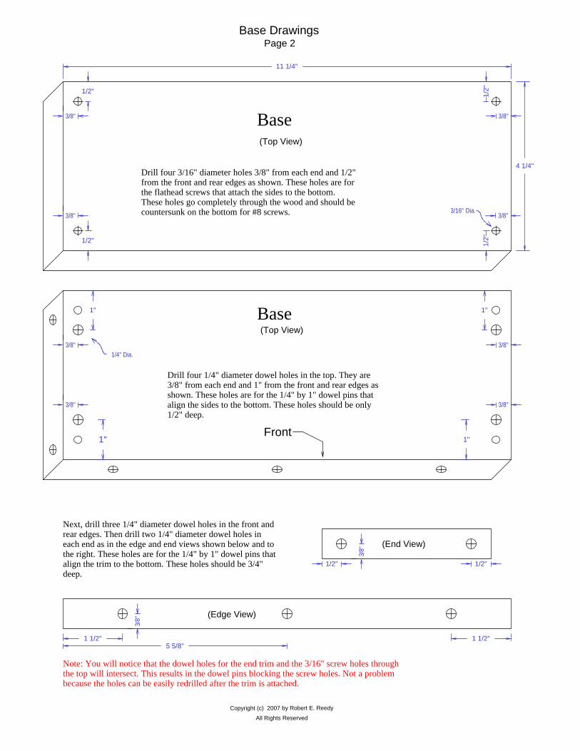
Note: You will notice that the dowel holes for the end trim and the 3/16" screw holes through the top will intersect. This results in the dowel pins blocking the screw holes. Not a problem because the holes can be easily redrilled after the trim is attached.
5 5/8"1 1/2" 1 1/2"
(Edge View)
3/8"
Next, drill three 1/4" diameter dowel holes in the front and rear edges. Then drill two 1/4" diameter dowel holes in each end as in the edge and end views shown below and to the right. These holes are for the 1/4" by 1" dowel pins that align the trim to the bottom. These holes should be 3/4" deep.
1/2" 1/2"
3/8"
(End View)
Base Drawings
4 1/4"
11 1/4"
1/2"
1/2"
3/8"
3/8" 3/8"
3/8"
1/2"
1/2"
3/16" Dia.
(Top View)
Drill four 3/16" diameter holes 3/8" from each end and 1/2" from the front and rear edges as shown. These holes are for the flathead screws that attach the sides to the bottom. These holes go completely through the wood and should be countersunk on the bottom for #8 screws.
Page 2
Base
3/8"
3/8"
1"1"
(Top View)
Drill four 1/4" diameter dowel holes in the top. They are 3/8" from each end and 1" from the front and rear edges as shown. These holes are for the 1/4" by 1" dowel pins that align the sides to the bottom. These holes should be only 1/2" deep.
Front
1"1"
1/4" Dia.
3/8"
3/8"
Base

All Rights Reserved
Copyright (c) 2007 by Robert E. Reedy
3/8"
3/8"
1 1/2"1 1/2"5 5/8" 5 5/8"
1 1/4"Front & Rear Trim (Edge View)
Drill the dowel holes in the trim pieces as shown in the drawings below. These holes should be 1/2" deep.
Here are top views of the bottom trim pieces. The trim pieces will be attached to the bottom with 1/4" dowel pins. You must drill the 1/4" dowel holes to the exact dimensions as shown below for a good fit.
1/2" 1/2"
5 3/4"
3/8"
3/8"
1 1/4" End Trim (Edge View)
Cut a section from the front trim and both end trim pieces as shown in the drawings to the right and below. The dotted lines represent where to cut. removing this material makes it look like the clock is sitting on legs. It is not necessary to remove material from the rear trim.
Bottom(Top View)
Here is a top view showing the four trim pieces attached to the bottom with the 1/4" dowel pins. As mentioned before, the four screw holes that will be blocked with the dowel pins will need to be re-drilled after the trim is glued in place.
1 1/2"1 1/2"
R1/2" 1/2"
End Trim (Edge View)
1 1/2"1 1/2"
R1/2" 1/2"
(Edge View)End Trim
Page 3
Base Trim Drawings
11 1/4"
3/4" 45° 45°Front and Rear Trim (Two required)(Top View)
12 3/4"
4 1/4"
3/4" 45° 45°End Trim (Two required)(Top View)
5 3/4"

14 3/4"
4 1/4"
Sid
e(T
wo
Re q
uire
d )
2 1/4"
1 1/4"
Bottom View of Side Pieces
3/8"
1/2"
1"1"
1/2"
Top View of Side Pieces
3/16"
1/4"
1 1/4"
Left Side
3/16"
1/4"
1 1/4"
Right Side
Cut the back rabbets, dial mount slots, and decorative bead.
Copyright (c) 2007 by Robert E. ReedyAll Rights Reserved
Drill two 1/8" pilot holes in the top and bottom of each side as shown in the drawings above. These pilot holes should be 1/2" from each edge and about 3/4" deep. These holes are for the #8 woodscrews used to secure the sides to the base.
Next, drill two 1/4" dowel pin holes in the top and bottom of each side. These dowel pin holes should be 1" from each edge and 1/2" deep. Dowel pins are used to keep the sides properly aligned with the base.
3/8"
1/2" 1/2"
1" 1"
Use your router to make a 1/4" bead along the front edge of each side as shown.
Cut the rabbets in each side for the rear cover. They are 1/2" wide and 3/16" deep.
Cut a slot in each side to hold the clock dial backing plate in position. These slots are 1/4" wide and 1/4 inch deep.
Page 4Case Sides Drawings

Copyright (c) 2007 by Robert E. ReedyAll Rights Reserved
Drill pilot holes for the brass door hinges using a 1/16" bit. Drill these holes about 3/8" deep.
Note: The exact location of the hinge pilot holes depends on the hinges you will be using.
You will need solid brass or brass plated hinges that are from 1" to 1 1/4" high and from 1" to 1 1/4" wide. These hinges can be found at most hardware stores or hobby shops. The ones I used on this clock are 1" high and 1" wide when fully opened. They also create a 1/8" gap between the door and right side of the clock when the hinge is installed and the door is mounted. I suggest you obtain the hinges before drilling the pilot holes and mark the location of the holes using the hinges you will be using. This will ensure the holes are drilled accurately.
14 3/4"
4 1/4"
Rig
ht S
ide
1"
1/4"
1/4"
1"
Side Hinges LocationPage 5
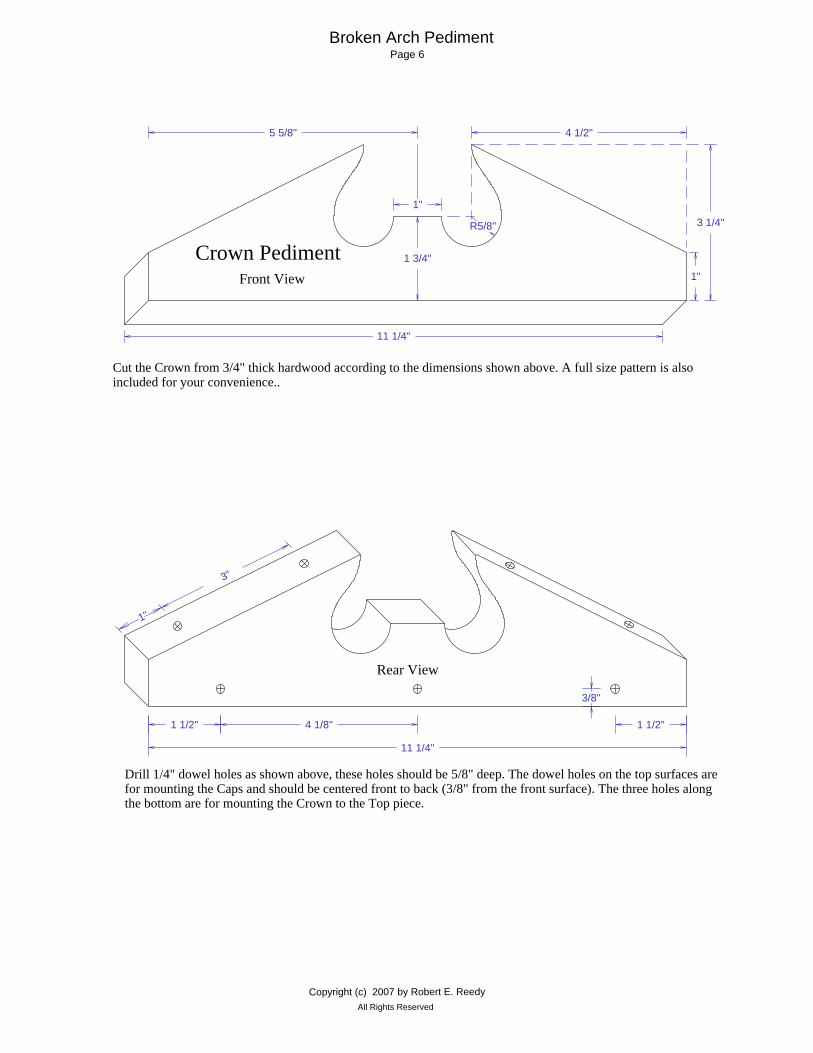
Broken Arch PedimentPage 6
Cut the Crown from 3/4" thick hardwood according to the dimensions shown above. A full size pattern is also included for your convenience..
Drill 1/4" dowel holes as shown above, these holes should be 5/8" deep. The dowel holes on the top surfaces are for mounting the Caps and should be centered front to back (3/8" from the front surface). The three holes along the bottom are for mounting the Crown to the Top piece.
1 1/2"1 1/2"
11 1/4"
3/8"
4 1/8"
Rear View
1"
3"
1 3/4"
1"
R5/8"
1"
3 1/4"
11 1/4"
5 5/8" 4 1/2"
Front View
Crown Pediment
Copyright (c) 2007 by Robert E. ReedyAll Rights Reserved

All Rights ReservedCopyright (c) 2007 by Robert E. Reedy
R3/8"
7/8"
1 3/4"
5 1/8"
Side ViewEnd View
6"
Make two Caps from 3/4" hardwood as shown above.
Create the bead along the edges with your router using a 3/8" radius beading bit. The bottom surface should be 7/8" wide by 5 1/8" long. This provides for the bottom surface of the Caps to extend 1/16" over the edges of the Crown.
Drill 1/4" dowel holes as shown above, these holes should be 1/2" deep.
1 1/4"
1"
Finial Seat (1/8" Thick)
Make the Finial Seat from 1/8" thick hardwood as shown above. Drill a hole through the center the same diameter as the outer diameter of the Finial mounting screw.
6"
Cap (2 required) (3/4" Thick)
1 3/4"
Top View of Finished Cap
3"1 1/16" 1 1/16"
Crown CapsPage 7
1 1/4"
1/2" End View
(4 Required)
45° 45°
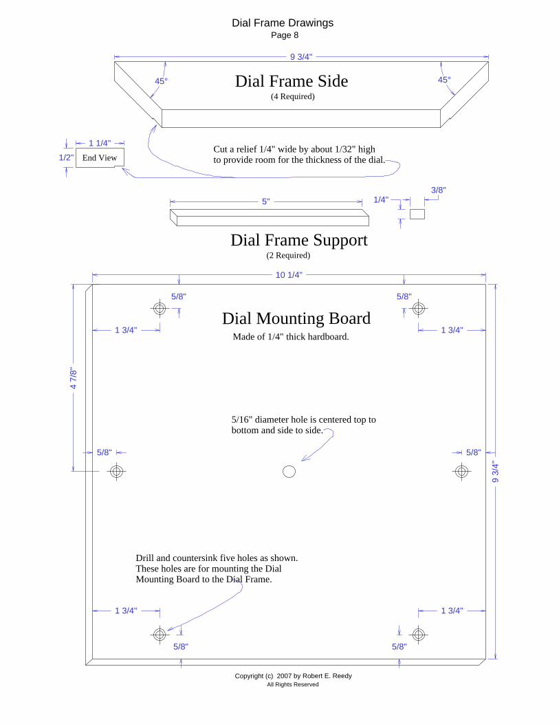
9 3/4"
Dial Frame Side
Cut a relief 1/4" wide by about 1/32" high to provide room for the thickness of the dial.
Page 8
1/4"3/8"
(2 Required)Dial Frame Support
5"
5/16" diameter hole is centered top to bottom and side to side.
Dial Mounting Board Made of 1/4" thick hardboard.
9 3/
4"
10 1/4"
1 3/4" 1 3/4"
5/8"
5/8"
1 3/4" 1 3/4"
5/8"
5/8"
5/8"
4 7/
8"
5/8"
Drill and countersink five holes as shown. These holes are for mounting the Dial Mounting Board to the Dial Frame.
All Rights ReservedCopyright (c) 2007 by Robert E. Reedy
Dial Frame Drawings

7 1/2"
Door Frame Divider(1 Required)
Top View
Bottom View
1"
3/4"End View
Side View
7 1/2"
8 1/2"
14 1
/2"
3/4"
45°
Do o
r Fra
me
Sid e
(2 R
equi
red)
5/16"
5/16"1/2"
3/8"
1/2"Lower Side Glass Retainer (2 Required)
4 3/4"1/2"
3/8"
End View
7 1/2"
1/2"Top & Bottom Glass Retainer (2 Required)
1/2"
3/8"
End View
8 1/4"
1/2"Upper Side Glass Retainer (2 Required)
1/2"
3/8"
End View
Middle Glass Retainer (2 Required)
7 1/2"
5/16"3/8"
End View
Glass Retainers
3/4"
9 1/2"
45°(2 Required)
Door Frame Top & Bottom
3/4"End View
1"
1/2"
1/2"
Page 9
All Rights ReservedCopyright (c) 2007 by Robert E. Reedy
Door Parts Drawings

Copyright (c) 2007 by Robert E. ReedyAll Rights Reserved
9 3/4"
1/2"Back Mounting Strip (2 Required)1/2"
1/2"
End View
5 3/8"
5"
5"
2"2"
4"
4"
10 3/4"
14 3/4"
Back Cover
Movement Access Cutout
1/4"
Cut out a hole as shown for access to the movement.
Back CoverPage 10
Drill and countersink ten holes for #6 flat head screw along the edges as shown. Thgey should be 1/4" from the edge of the Back. These holes are for mounting the Back to the Case.
If you will be mounting a speaker on the Back Cover, use the Speaker Holes Pattern to layout and center punch the holes. Be sure you have clearance from the edges of the cover and the wires won't interfere with moving parts. Don't place the speaker in the lower half of the clock as it would be visible through the lower door glass.

Attach the Bottom Trim to the Bottom with 1/4" dowel pins and glue. After the glue has completely dried, sand all surfaces so the corners look good and the top surface is smooth.
Copyright (c) 2007 by Robert E. ReedyAll Rights Reserved
Next, use a 5/16" radius beading bit to create a bead around all four edges as shown.
Attach a Back Mounting Strip to the Bottom with glue and 1" brads as shown. The strip should be 3/4" from each end of the Bottom and 3/16" from the rear of the Bottom.
3/4 "
3/4 "
3/16 "
Base AssemblyPage 11

Apply glue to the mating surfaces and dowel pins and assemble the Caps to the Crown Face as shown. An easy way to clamp the Caps to the Crown Face is with rubber bands. Use as many rubber bands as necessary to securely hold the Caps in place until the glue dries.
Next apply glue to the mating surfaces and attach the Finial Seat as shown above. Temporarily secure the Finial Seat with a flathead screw until the glue dries. Be sure the Finial Seat is positioned squarely.
Attach a Back Mounting Strip to the underside of the Top with glue and 1" brads as shown. The strip should be 3/4" from each end and 3/16" from the rear of the Top.
Apply glue to dowel pins and mating surfaces of the Top and Crown. Clamp securely until the glue is dry.
3/4 "
3/4 "
3/16 "
Attach the Finial
Copyright (c) 2007 by Robert E. ReedyAll Rights Reserved
Top AssemblyPage 12
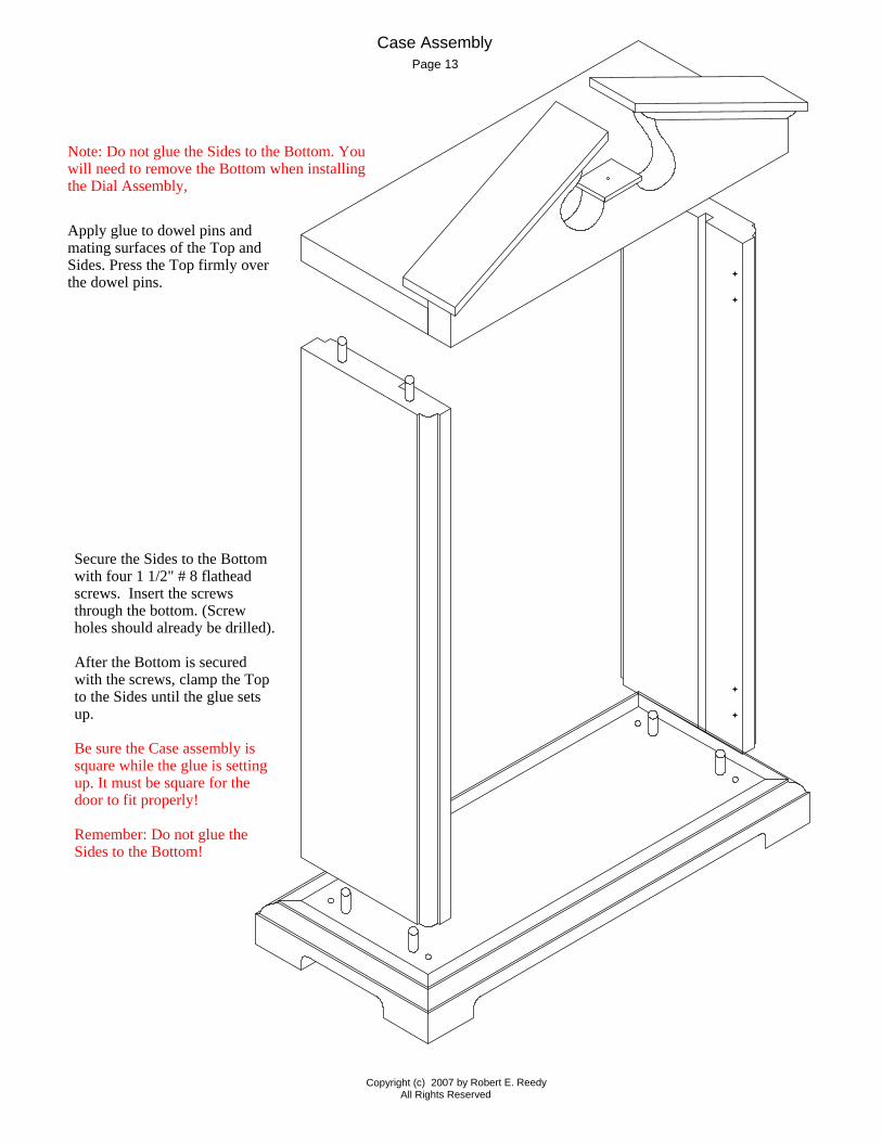
Note: Do not glue the Sides to the Bottom. You will need to remove the Bottom when installing the Dial Assembly,
Apply glue to dowel pins and mating surfaces of the Top and Sides. Press the Top firmly over the dowel pins.
Secure the Sides to the Bottom with four 1 1/2" # 8 flathead screws. Insert the screws through the bottom. (Screw holes should already be drilled).
After the Bottom is secured with the screws, clamp the Top to the Sides until the glue sets up.
Be sure the Case assembly is square while the glue is setting up. It must be square for the door to fit properly!
Remember: Do not glue the Sides to the Bottom!
Page 13Case Assembly
Copyright (c) 2007 by Robert E. ReedyAll Rights Reserved
Copyright (c) 2007 by Robert E. ReedyAll Rights Reserved
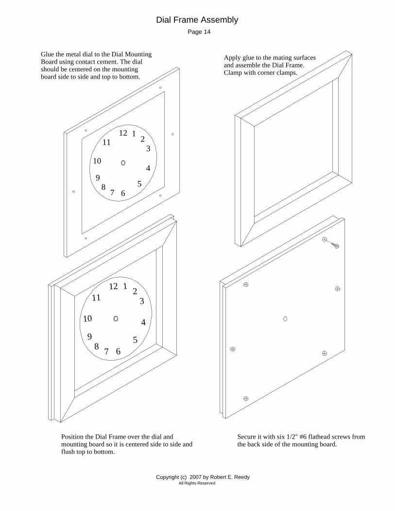
Secure it with six 1/2" #6 flathead screws from the back side of the mounting board.
Position the Dial Frame over the dial and mounting board so it is centered side to side and flush top to bottom.
Dial Frame Assembly
12
6
3
9
12
78
10
11
4
5
12
6
3
9
1 2
78
10
11
4
5
Glue the metal dial to the Dial Mounting Board using contact cement. The dial should be centered on the mounting board side to side and top to bottom.
Apply glue to the mating surfaces and assemble the Dial Frame. Clamp with corner clamps.
Page 14
Copyright (c) 2007 by Robert E. ReedyAll Rights Reserved
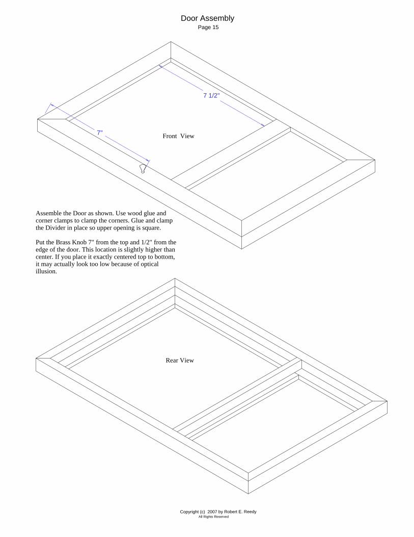
Rear View
Door AssemblyPage 15
Front View
"7 1/2
"7
Assemble the Door as shown. Use wood glue and corner clamps to clamp the corners. Glue and clamp the Divider in place so upper opening is square.
Put the Brass Knob 7" from the top and 1/2" from the edge of the door. This location is slightly higher than center. If you place it exactly centered top to bottom, it may actually look too low because of optical illusion.

Copyright (c) 2007 by Robert E. ReedyAll Rights Reserved
4 3/4"
1/4"
4 7/8"
3/8"
12 12
3
4567
8
9
1011
Back Side of Door Dial Frame
Magnetic Catch Installation
Note: An easy way to ensure the screw head lines up correctly with the magnet in the catch is to wait until the clock case is assembled and the door is mounted. then, you can place the screw head on the magnet and close the door so the point of the screw makes a mark on the inside of the door. This will be the exact location for the screw.
For the Door, you only need a 1/4" # 6 flathead screw to contact the magnetic latch. If a washer comes with your latch, you can discard it.
Drill a 1/16" pilot hole hole in the DoorFrame for the screw as shown to the right. Do not drill the hole completely through!
Drill a hole in the Dial Frame for the magnetic catch as shown above. ( I recommend using a brad point drill bit because it will cut a cleaner hole than a common twist drill.) The back side of the Dial Frame will be covered by the mounting board. I won't matter if you drill the hole completely through.
The hole should be the correct size for the catch you're using. You may want to experiment on scrap wood to determine the exact size.
Install the catch by inserting it until it is flush with the surface of the wood.
Page 16

Install the glass panels as shown above.
Install the glass retainers as shown to the right. Since there is always a possibilty that the glass may need to be replaced, I recommend attaching the retainers with household cement.
If the glass needs to be replaced, you should be able to remove the retainers with minimal damage to the wood parts.
Choose a cement that is intended to be used with plastic and wood. Apply three small spots of cement on the edge of each retainer where the retainers contact the inner edges of the door frame. Clamp the retainers in position with spring clamps until the glue sets up.
Door Glass Installation
Copyright (c) 2007 by Robert E. ReedyAll Rights Reserved
Page 17
Copyright (c) 2007 by Robert E. ReedyAll Rights Reserved
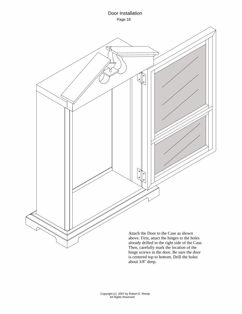
Attach the Door to the Case as shown above. First, attact the hinges to the holes already drilled in the right side of the Case. Then, carefully mark the location of the hinge screws in the door. Be sure the door is centered top to bottom. Drill the holes about 3/8" deep.
Door InstallationPage 18

Copyright (c) 2007 by Robert E. ReedyAll Rights Reserved
Remove the Base and install the Dial Assembly by sliding it up trough the slots in the sides. Apply a little household cement to the to the inside of the slots where the Dial Supports will touch and press the Dial Supports into the slots. If there is not a snug fit, you'll need to clamp them in place until the glue sets up.
Now, you can re-attach the Base to the Sides.
Page 19
Dial Assembly Installation
12
6
3
9
1 2
78
10
11
4
5
Dial Supports
Copyright (c) 2007 by Robert E. ReedyAll Rights Reserved
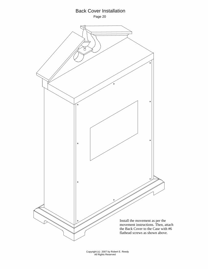
Install the movement as per the movement instructions. Then, attach the Back Cover to the Case with #6 flathead screws as shown above.
Back Cover InstallationPage 20

All Rights Reserved
Copyright (c) 2007 by Robert E. Reedy
Grid lin
es a
re 1
/4" a
part
Broken Arch Pediment Full Size PatternPage 21

Page 22
Speaker Holes Pattern
Determine the desired location for the speaker holes. Cut out the pattern and tape it to the desired location on the Back Cover. Use a center punch to mark the location of each hole. Then, removem the pattern and drill the holes with a 3/16" bit.
All Rights Reserved
Copyright (c) 2007 by Robert E. Reedy

More Plans from: www.bobsplans.com
Router Table Workbench Dog House Picnic Table Octagon Table
6 Foot Bar Corner Desk Book Case Mantel Clock Redwood Planter
Wheelbarrow Spoke Wheel Panel Saw Trellis Wheelbarrow
Pocket Hole Jig Tenoning Jig Table Saw Sled Drill Press Table