bs en 50272-2_battery room ventilation.pdf
DESCRIPTION
BS EN 50272-Battery Room VentilationTRANSCRIPT
BRITISH STANDARD
Safety requirements for secondary batteries and battery installations - Part 2: Stationary batteries
The European Standard EN 50272-2:2001 has the status of a British Standard
ICs 29.220.20; 29.220.30
NO COPYING WITHOUT BSI PERMISSION EXCEPT AS PERMIïTED BY COPYRIGHT LAW
BS EN 5 O 2 72-2 :2 O0 1
Copyright European Committee for Electrotechnical Standardization Provided by IHS under license with CENELEC
Not for ResaleNo reproduction or networking permitted without license from IHS
--````-`-`,,`,,`,`,,`---

BS EN 50272-2:2001
Amd. No.
National foreword
Date Comments
This British Standard, having been prepared under the direction of the Electrotechnical Sector Policy and Strategy Committee, was published under the authority of the Standards Policy and Strategy Committee on 4 September 2001
This British Standard is the official English language version of
The UK participation in its preparation was entrusted to Technical Committee PEIJ21, Secondary cells and batteries, which has the responsibility to:
EN 50272-212001.
-
- aid enquirers to understand the text;
present to the responsible European committee any enquiries on the interpretation, or proposals for change, and keep the UK interests informed;
monitor related international and European developments and promulgate them in the UK.
-
A list of organizations represented on this committee can be obtained on request to its secretary. Cross-references The British Standards which implement international or European publications referred to in this document may be found in the BSI Standards Catalogue under the section entitled “International Standards Correspondence Index”, or by using the “Find” facility of the BSI Standards Electronic Catalogue. A British Standard does not purport to include all the necessary provisions of a contract. Users of British Standards are responsible for their correct application. Compliance with a British S t a n d a r d does n o t of i tselfconfer immunity from legal obligations.
Summary of pages This document comprises a front cover, an inside front cover, the EN title page, pages 2 to 31 and a back cover. The BSI copyright date displayed in this document indicates when the document was last issued.
Amendments issued since publication
P BSI 4 September 2001
I ISBN O 580 38440 3
Copyright European Committee for Electrotechnical Standardization Provided by IHS under license with CENELEC
Not for ResaleNo reproduction or networking permitted without license from IHS
--````-`-`,,`,,`,`,,`---

EUROPEAN STANDARD EN 50272-2 NORMEEUROPÉENNE
EUROPÄISCHE NORM June 2001
ICs 29.220.20
English version
Safety requirements for secondary batteries and battery installations Part 2: Stationary batteries
Règles de sécurité pour les batteries et les installations de batteries Partie 2: Batteries stationnaires
Sicherheitsanforderungen an Batterien und Batterieanlagen Teil 2: Stationäre Batterien
This European Standard was approved by CENELEC on 2000-08-01. CENELEC members are bound to comply with the CENICENELEC Internal Regulations which stipulate the conditions for giving this European Standard the status of a national standard without any alteration.
Up-to-date lists and bibliographical references concerning such national standards may be obtained on application to the Central Secretariat or to any CENELEC member.
This European Standard exists in three official versions (English, French, German). A version in any other language made by translation under the responsibility of a CENELEC member into its own language and notified to the Central Secretariat has the same status as the official versions.
CENELEC members are the national electrotechnical committees of Austria, Belgium, Czech Republic, Denmark, Finland, France, Germany, Greece, Iceland, Ireland, Italy, Luxembourg, Netherlands, Norway, Portugal, Spain, Sweden, Switzerland and United Kingdom.
CENELEC European Committee for Electrotechnical Standardization
Comité Européen de Normalisation Electrotechnique Europäisches Komitee fü r Elektrotechnische Normung
Central Secretariat: rue de Stassart 35, B - 1050 Brussels
~
O 2001 CENELEC - All rights of exploitation in any form and by any means reserved worldwide for CENELEC members.
Ref. No. EN 50272-2:2001 E
Copyright European Committee for Electrotechnical Standardization Provided by IHS under license with CENELEC
Not for ResaleNo reproduction or networking permitted without license from IHS
--````-`-`,,`,,`,`,,`---

Page 2 EN 50272-2:2001
Foreword
This European Standard was prepared by the Technical Committee CENELEC TC 21X Secondary cells and batteries.
The text of the draft was submitted to the formal vote and was approved by CENELEC on 2000-08-01.
The following dates were fixed:
- latest date by which the EN has to be implemented at national level by publication of an identical national standard or by endorsement
with the EN have to be withdrawn - latest date by which the national standards conflicting
Annexes designated "informative" are given for information only. In this standard, annexes A and B are informative.
(dop) 2001-12-01
(dûw) 2003-04-01
Copyright European Committee for Electrotechnical Standardization Provided by IHS under license with CENELEC
Not for ResaleNo reproduction or networking permitted without license from IHS
--````-`-`,,`,,`,`,,`---

Page 3 EN 50272-2~2001
Introductory note
For the preparation of EN 50272-2 the following European country's national standards have been taken into consideration:
Germany:
United Kingdom:
Sweden:
Switzerland:
Italy:
Netherlands:
Austria
France
DIN VDE 0510 Patt 2 Batteries and battery installations BS 61 33 for lead-acid batteries BS 61 32 for NiCd batteries SS 408 O1 10 relating parts for rechargeable batteries, erection and ventilation SEV 1000-1 and SEV 1000-2 relating parts of instructions for installations in buildings Doc. D.P.R. 547, art. 302 and 303 , Safely in battery installations CE1 21-6 Part 3 NEN I O10 relating parts of safety regulations for low voltage installations OVE-CI0 Part 2, Batteries and battery installations NF CI 5-1 O0 , article 554 Batteries d'accumulateurs Article ECIO, Règlement de securité contre l'incendie relatif aux établissemments recevant du public
Only those paragraphs have been considered where common agreement was found or specific need was recognised.
The described safety requirements comprise the protective measures to protect from hazards generated by the electricity, the electrolyte, and the explosive gases when using secondary batteries. In addition measures are described to maintain the functional safety of batteries and battery installations.
For the electrical safety (protection against electric shock) under clause 5 this document refers to HD 384.4.41 (IEC 60364441). The pilot function of this standard is fully observed by indication of cross-reference numbers of the relevant clauses. But interpretation is given where adoption to direct current (DC) circuits is required.
This safety standard comes into force with the date of publication and applies to all new batteries and battery installations. Previous installations shall conform with the existing national standards at the time of installation. In case of redesign of old installations this standard applies.
Copyright European Committee for Electrotechnical Standardization Provided by IHS under license with CENELEC
Not for ResaleNo reproduction or networking permitted without license from IHS
--````-`-`,,`,,`,`,,`---

Page 4 EN 50272-2:2001
Contents
Page
1
2
3
4
5
6
7
8
9
10
Il
12
13
14
scope ................................................................................................................................................. 5
Main applications ............................................................................................................................... 5 Normative references ......................................................................................................................... 5 General definitions ............................................................................................................................. 6
Protection against electric shock ........................................................................................................ 8
Prevention of short circuits and protection from other effects of electric current ............................... 14
Provisions against explosion hazards ............................................................................................... 16
Provision against electrolyte hazard ................................................................................................. 19
Disconnection and separation ........................................................................................................... 14
Accommodation, housing ................................................................................................................. 20
Charge current requirements ............................................................................................................ 22
Identification labels, warning notices and instructions for use, installation and maintenance ............. 23
Transportation, storage, disposal and environmental aspects ........................................................... 24
Inspection and monitoring ................................................................................................................ 24
Annex A (informative) Charging methods. modes of operation ................................................................... 25
Annex B (informative) Calculation of safety distance d to protect against explosion hazards ...................... 29
Copyright European Committee for Electrotechnical Standardization Provided by IHS under license with CENELEC
Not for ResaleNo reproduction or networking permitted without license from IHS
--````-`-`,,`,,`,`,,`---

Page 5 EN 50272-2:2001
1 Scope
This European Standard applies to stationary secondary batteries and battery installations with a maximum voltage of DC 1500 V (nominal) and describes the principal measures for protections against hazards generated from:
- electricity, - gas emission, - electrolyte.
It provides requirements on safety aspects associated with the erection, use, inspection, maintenance and disposal.
It covers lead-acid and NiCd batteries.
2 Main applications
Examples for the main applications are: - Telecommunications, - Power Station Operation, - - Uninterruptible Power Supplies, - Stationary Engine Starting, - Photovoltaic Systems.
Central Emergency Lighting and Alarm Systems,
3 Normative references - . This European Standard incorporates by dated or undated reference, provisions from other publications. These normative references are cited at the appropriate places in the text and the publications are listed hereafter. For dated references, subsequent amendments to or revisions of any of these publications apply to this European Standard only when incorporated, in it by amendment or revision. For undated references the latest edition of the publication referred to applies (i nci ud i ng am end ments).
EN 166 Eye protection EN 345 EN 50091-1-2
Safety footwear for professional use Uninterruptible power systems (UPS) General and safety requirements for UPS used in restricted access locations Electronic equipment for use in power installations Electrical apparatus for explosive gas atmospheres Part I O : Classification of hazardous areas (IEC 60079-10) Degrees of protection provided by enclosures (IP code) (IEC 60529) Vented nickel-cadmium prismatic rechargeable single cells (IEC 60623) Stationary lead-acid batteries - General requirements and methods of test Part 1 : Vented types (IEC 60896-1 ) Stationary lead-acid batteries - General requirements and methods of test Part 2: Valve-regulated types (IEC 60896-2) Hand tools for live working up to 1 kV a.c. and 1,5 kV d.c. (IEC 60900, mod.) Safety of information technology equipment (IEC 60950, mod.) Methods of measurement of touch-current and protective conductor current ( I EC 60990)
EN 50178 EN 60079-10
EN 60529
EN 60623
EN 60896-1
EN 60896-2
EN 60900
EN 60950 EN 60990
Copyright European Committee for Electrotechnical Standardization Provided by IHS under license with CENELEC
Not for ResaleNo reproduction or networking permitted without license from IHS
--````-`-`,,`,,`,`,,`---

Page 6 EN 50272-2~2001
4
4.1
4.2
EN 61 140
EN 61660-1
EN 61660-2
HD 193
HD 366
HD 384.4.41
HD 384.4.43
HD 384.553
HD 384.5.54
HD 384.7.706
HD 625.1
IEC 60050-486
IEC/TR 60755 IEC 61201 IEC 61340-4-1
IS0 3864
Protection against electric shock - Common aspects for installation and equipment (IEC 61 140) Short-circuit currents in d.c. auxiliary installations in power plants and substations - Part 1: Calculation of short-circuit currents (IEC 61660-1) Short-circuit currents in d.c. auxiliary installations in power plants and substations - Part 2: Calculation of effects (IEC 61660-2) Voltage bands for electrical installations of buildings (IEC 60449) Classification of electrical and electronic equipment with regard to protection against electric shock (IEC 60536) Electrical installations of buildings Part 4: Protection for safety - Chapter 41: Protection against electric shock (IEC 60364-4-41, mod.) Electrical installation of building Part 4: Protection for safety -- Chapter 43: Protection against overcurrent (IEC 60364-4-43) Electrical installation of buildings Part 5: Selection and erection of electrical equipment (IEC 60364-5-53) Electrical installations of buildings Part 5: Selection and erection of electrical equipment Chapter 54: Earthing arrangements and protective conductors (IEC 60364-5-54, mod.) Electrical installation of buildings Part 7: Requirements for special installations or locations Section 706: Restrictive conductive locations (IEC 60364-7-706) Insulation coordination for equipment in low-voltage systems Part 1: Principles, requirements and tests (IEC 60664-1) International Electrotechnical Vocabulary, Chapter 486: Secondary cells and batteries General requirements for residual current operated protective devices Extra-low voltage (ELV) - Limit values Electrostatics - Part 4: Standard test methods for specific applications - Section 1: Electrostatic behaviour of floor coverings and installed floors Safety colours and safety signs
EC Directive 91/157/EEC
EC Directive 93/86/EEC
Batteries and accumulators containing certain dangerous substances Adaptation to technical progress of Directive 91/157/EEC
General definitions
(secondaty) cell; (rechargeable) cell; single cell
An assembly of electrodes and electrolyte which constitutes the basic unit of a secondary battery. (see IEC 60050-486-01-02)
NOTE This assembly is contained in an individual cace and clased by a cover.
vented (secondary) cell
A secondary cell having a cover provided with an opening through which gaseous products may escape. (see IEC 60050-486-01-18)
Copyright European Committee for Electrotechnical Standardization Provided by IHS under license with CENELEC
Not for ResaleNo reproduction or networking permitted without license from IHS
--````-`-`,,`,,`,`,,`---

Page 7 EN 50272-2:2001
4.3
4.4
4.5
4.6
4.7
4.8
4.9
valve regulated (secondary) cell
A secondary cell which is closed under normal conditions but has an arrangement which allows the escape of gas if the internal pressure exceeds a predetermined value. The cell cannot normally receive addition to the electrolyte. (see IEC 60050-486-01 -20)
gastight sealed (secondary) cell
A secondary cell which remains closed and does not release either gas or liquid when operated within the limits of charge and temperature specified by the manufacturer. The cell may be equipped with a safety device to prevent dangerously high internal pressure. The cell does not require addition to the electrolyte and is designed to operate during its life in its original sealed state. (see IEC 60050-486-01-21)
secondary battery
Two or more secondary cells connected together and used as a source of electrical energy. (SW IEC 60050-486-01-03)
lead-acid battery
A secondary battery in which the electrodes are made mainly from lead and the electrolyte is a sulphuric acid solution (H2Sû4). (see IEC 60050-486-01-04)
nickel-cadmium battery
An alkaline secondary battery in which the positive material is made mainly from nickel and the negative material is made mainly from cadmium (see IEC 60050-486-01-07). The electrolyte is an alkaline solution (potassium hydroxide, KOH).
stationary battery
A secondary battery which is designed for service in a fixed location and is not habitually moved from place to place during the operating life. It is permanently connected to the DC power supply (fixed installation).
monobloc battery
A secondary battery in which the plate packs are fitted in a multi-compartment container. (SW IEC 60050-486-01-17)
4.10 electrolyte
A liquid or solid phase containing mobile ions which render the phase ionically conductive. (SW IEC 60050-486-02-19)
4.11 gassing; gas emission
The formation of gas produced by electrolysis of the electrolyte. (SW IEC 60050-486-03-24)
4.12 charge; charging (of a battery)
An operation during which a battery receives from an external circuit electrical energy which is converted into chemical energy. (see IEC 60050-486-01-1 1)
4.13 float charge
An operation during which the battery is permanently connected to a source of constant voltage sufficient to maintain the battery in fully charged condition and to recharge the battery in a specified time. (see IEC 60050-486-04-1 O, floating battery)
4.14 float (charge) voltage
The constant voltage needed to keep the cell or battery charged.
Copyright European Committee for Electrotechnical Standardization Provided by IHS under license with CENELEC
Not for ResaleNo reproduction or networking permitted without license from IHS
--````-`-`,,`,,`,`,,`---
Page 8 EN 50272-2~2001
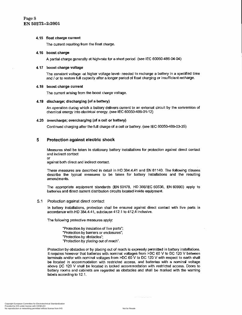
4.15 float charge current
The current resulting from the float charge.
4.16 boost charge
A partial charge generally at high-rate for a short period. (see IEC 60050486-04-04)
4.17 boost charge voltage
The constant voltage -at higher voltage level- needed to recharge a battery in a specified time and / or to restore full capacity after a longer period of float charging or insufficient recharge.
4.18 boost charge current
The current arising from the boost charge voltage.
4.19 discharge; discharging (of a battery)
An operation during which a battery delivers current to an external circuit by the conversion of chemical energy into electrical energy. (see IEC 60050-486-01-12)
4.20 overcharge; overcharging (of a cell or battery)
Continued charging after the full charge of a cell or battery. (see IEC 60050-48803-35)
5 Protection against electric shock
Measures shall be taken in stationary battery installations for protection against direct contact and indirect contact or against both direct and indirect contact.
These measures are described in detail in HD 384.4.41 and EN 61 140. The following clauses describe the typical measures to be taken for battery installations and the resulting amendments.
The appropriate equipment standards (EN 50178, HD 366/IEC 60536, EN 60990) apply to batteries and direct current distribution circuits located inside equipment.
5.1 Protection against direct contact
In battery installations, protection shall be ensured against direct contact with live parts in accordance with HD 384.4.41, subclause 412.1 to 412.4 inclusive.
The following protective measures apply:
"Protection by insulation of live parts"; "Protection by barriers or enclosures"; "Protection by obstacles"; "Protection by placing out of reach".
Protection by obstacles or by placing out of reach is expressly permitted in battery installations. It requires however that batteries with nominal voltages from >DC 60 V to DC 120 V between terminals and/or with nominal voltages from >DC 60 V to DC 120 V with respect to earth shall be located in accommodation with restricted access, and batteries with a nominal voltage above DC 120 V shall be located in locked accommodation with restricted access. Doors to battery rooms and cabinets are regarded as obstacles and shall be marked with the warning labels according to 12.1.
Copyright European Committee for Electrotechnical Standardization Provided by IHS under license with CENELEC
Not for ResaleNo reproduction or networking permitted without license from IHS
--````-`-`,,`,,`,`,,`---

Page 9 EN 60272-2:2001
Batteries with nominal voltages up to or equal DC 60 V do not require protection against direct contact, as long the whole installation corresponds to the conditions for SELV (safety extra low voltage) and PELV (protective extra low voltage) (see 5.3.1).
Short circuit protection may be required (see clause 7.1).
If protection by barries or enclosures is applied, a degree of protection EN 60529 IP 2X or IPXXB shall at least be used.
5.2 Protection against indirect contact In battery installations, protection against indirect contact shall be applied in accordance with HD 384.4.41, clause 41 3.
The following measures can be selected:
”Protection by automatic disconnection of supply”; ”Protection by use of Class I I equipment or by equivalent insulation”; “Protection by non-conducting locations” “Protection by earth-free local equipotential bonding” “Protection by electrical separation”.
(used in specific applications only); (used in specific applications only);
A nominal touch voltage of DC 120 V shall not be exceeded (see HD 193, HD 384.4.41 and IEC 61201).
Certain of these methods of protection require a protective conductor. Protective conductors or conductors with a protective function shall not be disconnected by a switching device. No switching device is permitted in a protective conductor. They shall not contain overcurrent protection devices (see HD 384.4.41, clause 41 3). For dimensioning the cross-sectional areas of protective conductors, see HD 384.5.54.
Battery stands or battery cabinets made from metal shall either be connected to the protective conductor or insulated from the battery and the place of installation. This insulation shall correspond to the conditions for protection by insulation according to HD 384.4.41, subclause 413.2. Other simultaneously accessible conductive parts, ¡.e. metal ducts, shall be out of reach. For requirements on creepage distances and clearances, see HD 625.1, using a value of 4000 V for the high-voltage impulse test.
The following protective devices are used with direct current, as applicable to the type of power system:
a) fuses; b) overcurrent protective devices; c) Residual current or differential protective devices (RCD’s), suitable for DC current;
NOTE Residual current protective devices (RCD’s) in accordance with IEC 60755 shall be of type B suitable for DC faul current.
d) e)
insulation monitoring devices (e.g. in IT-systems); fault-voltage operated protective devices (see HD 384.4.41, subclause 41 3.1.4.4).
5.2.1 Protection by automatic disconnection of supply
5.2.1.1 TN-System In a TN-system (see HD 384.4.41, subclause 413.1.3) the positive or negative terminal (see Figure 1 and Figure 2) or the central point (in special cases also an noncentral point) of the battery installation shall be connected to earth.
Copyright European Committee for Electrotechnical Standardization Provided by IHS under license with CENELEC
Not for ResaleNo reproduction or networking permitted without license from IHS
--````-`-`,,`,,`,`,,`---

Page 10 EN 50272-2~2001
The exposed conductive parts of the equipment shall be connected to the protective conductor (PE)", the PEN-conductor (PEN)", or the earthing functional and protective conductor (FPE)3', which is connected to the point on the battery having earth potential. Additional earthing of the protective conductor may be required in order to ensure that its potential deviates as little as possible from earth potential.
For fixed mounted electrical equipment the disconnecting time shall be within 5 s after a fault occurs.
NOTE For portable equipment and socket-ouüet circuits HD 34.4.41, subclause 41 3.1.3.3 applies.
L+ n. I I
7- I
battery
Figure1 - TN system with separate protective conductor (PE) in the entire system (TNS network)
In the TN-S system, the protective conductor (PE) must be free of load current.
I
battery I -.-.-.-.-. ! load
Figure 2 - TN system with functional earthing and protective (FPE, PEN) combined with an external line conductor (TN-C) system)
In the TN-C system for DC-installations, the protective conductor and the earthed line conductor cawing the load current are combined. The cross-sectional area of the PEN or FPE conductor shall be at least 10 mm2 Cu.
') For definitions see HD 384.5.54. 2, Introduced with reference to HD 384.5.54. 3, For definitions see EN 60950.
Copyright European Committee for Electrotechnical Standardization Provided by IHS under license with CENELEC
Not for ResaleNo reproduction or networking permitted without license from IHS
--````-`-`,,`,,`,`,,`---

Page 11 EN 50272-2:2001
5.2.1.2 lT-System In a TT-System (see Figure 3) the positive or negative pole or another point on the battery installation shall be connected to earth (system earth electrode).
The exposed conductive parts of the electrical installation may be earthed individually, in groups or collectiyely to a common earth electrode which is separate from the system earth electrode.
All exposed conductive parts collectively protected by the same protective device, shall be connected together with protective conductors to an earth electrode common to all those parts. Simultaneously accessible conductive parts shall be connected to the same earth electrode (HD 384.4.41, subclause 413.1.4.1).
Apart from the protective devices mentioned in 5.2, fault-voltage operated protective devices are also applicable (HD 384.4.41, subclause 413.1.4.4 )
In TT-system circuits, when the protective device is an overcurrent protective device, the disconnecting time for all equipment shall be within 5s. after a fault occurs. According to HD 384.4.41, subclause 413.1.4.4 overcurrent protective devices are only applicable for protection against indirect contact, where a very low value earth resistor R a exists.
NOTE parts.
For discrimination purpose disconnecting times of up to 1 s are admitted, when using residual current devices.
5 is the sum of the resistance of the earth electrode and the protective conductors for the exposed conductive
battery
Figure 3 - TT system
5.2.1.3 IT-System In an IT system (see Figure 4) no point of the battery installation is directly connected to earth. It shall be insulated from earth or connected to earth through a sufficiently high impedance (e.g. through an insulation monitoring device).
All exposed conductive parts of equipment shall be earthed individually, in groups or collectively to a common earth electrode via a protective conductor.
Exposed conductive parts which are protected by a common protective device shall be connected by protective conductors to a common earth electrode. Exposed conductive parts which are simultaneously accesible shall be connected to the same earth electrode (HD 384.4.41, subclause 413.1.5.1).
Copyright European Committee for Electrotechnical Standardization Provided by IHS under license with CENELEC
Not for ResaleNo reproduction or networking permitted without license from IHS
--````-`-`,,`,,`,`,,`---

Page 12 EN 50272-2~2001
Apart from the safety devices mentioned in 5.2, insulation monitoring devices suitable for DC voltages may also be used.
In an IT-system, disconnection is not required at the occurrence of the first fault from a live part to the exposed conductive parts or to earth. If an insulation monitoring device is provided, this device shall initiate an audible andlor visual signal (HD 384.4.41, subclause 413.1 5.4).
Precautions must be taken to prevent hazardous touch voltage levels in the event of a second fault (e.9. disconnection by an overcurrent protective device, a residual current or fault voltage protective device) (see HD 384.4.41, subclause 413.1.5.8).
I I +
I I
insulation mmitdng
battery device -.-.-.-.-.
load I
Figure 4 - IT system
5.2.1.4 Intermediate DC current circuits with electrical connection to the AC supply
Systems of this type (Figure 5) are used, for example, in intermediate DC circuits of converter devices, e.g. UPS systems according to EN 50091 -1-2. Overcurrent protective devices are necessary in all conductors which lead to the battery.
7 1 battej I 7- PE I /
Figure 5 - Convertors with intermediate DC circuit (IT-System) (Example)
It shall be ensured that no AC voltage appears at the battery terminals whose rms voltage value with respect to earth is above the maximum battery charging voltage. To ensure this, the DC system can be provided with an appropriate detection device, which either monitors the fault or disconnects the rectifier circuit.
Copyright European Committee for Electrotechnical Standardization Provided by IHS under license with CENELEC
Not for ResaleNo reproduction or networking permitted without license from IHS
--````-`-`,,`,,`,`,,`---

Page 13 EN 80272-2:2001
The protective provisions applied in the singlelthree-phase AC supply shall -where technically possible- be retained for the DC circuit, and if necessary extended by suitable ancillary components so that, in the event of a fault, no hazardous touch voltage (>AC 50V or > DC 120 V) remains at the exposed conductive parts of the equipment.
NOTE Residual current protective dev¡ces(RCDs) in accordance with IEC 60755 shall be of type B suitable for DC fault current.
5.2.2 Protection by use of Class II equipment or by equivalent insulation Protection by double or reinforced insulation must be employed for electrical equipment to comply with protection Class II according to HD 366AEC 60536 or equipment with equivalent insulation (see HD 384.4.41, subclause 413.2.1 . I )
5.2.3 Protection by electrical separation
For the application of protection by electrical separation see HD 384.4.41, subclause 413.5. A separation source must be used as the source of supply (HD 384.4.41, subclause 413.5.1 .I). An ”equivalent current source” within the meaning of HD 384.4.41, subclause 413.5.1.1 is a battery with isolated mounting during discharge. The separation shall comply with the test requirements for protective insulation in accordance with HD 384.4.41, subclause 41 3.2.4.
Protection against both direct and indirect contact
The protective provisions described in 5.3.1 (safety extra low voltage, SELV) and 5.3.2 (protective extra low voltage, PELV) shall only be used for battery installations with nominal voltages up to DC 120 V.
5.3
They simultaneously meet the requirements for protection against both direct and indirect contact.
NOTE In these mes the requirements for metal battery stands and cabinets specified in 5.2 do not apply.
5.3.1 Protection by SELV (safety extra !ow yoltage) or by PELV brotective extra !ow - voltage) in accordance with HD 384.4.41, subclause 41 1 .I
Protection against electric shock is ensured when the following conditions are met simultaneously:
- The power source complies with the safety requirements in accordance with HD 84.4.41, subclause 411.1.2, which reliably prevents the mains AC voltage exceeding the values specified in HD 384.4.41, subclause 41 1.1.1 on the DC side in the event of a fault.
- The arrangement of the circuits complies with HD 384.4.41, subclause 411.1.3. It shall be ensured that live parts or exposed conductive parts of SELV circuits cannot be connected to live parts or exposed conductive parts of circuits of an other circuit.
If the nominal DC voltage of the battery installation does not exceed DC 60 V and the above conditions are met, then in general, protection against direct contact with live parts may be omitted (exceptions see HD 384.7.706).
Where the nominal voltages exceeds DC 60 V then protection against direct contact with live parts shall be provided by
-
-
barriers or enclosures of minimum protection type EN 60529 IP 2X or IP XXB; or insulation which withstands a test voltage of AC 500 V for 1 minute, (see HD 384.4.41, subclause 411.1.4.3 for SELV circuits and HD 384.4.41, subclause 411.1.5.1 for PELV circuits; or protection through obstacles or distance which is expressly permitted in accordance with 5.1 in battery installations and battery rooms, see HD 384.4.41, subclause 412.3.
-
Copyright European Committee for Electrotechnical Standardization Provided by IHS under license with CENELEC
Not for ResaleNo reproduction or networking permitted without license from IHS
--````-`-`,,`,,`,`,,`---

Page 14 EN 50272-2~2001
5.3.2 Protection by FELV Cfunctional extra !ow yoltage) without protective separation If the nominal voltage does not exceed DC 120 V, but the conditions in accordance with 5.3.1,
- relevant to an electrochemical power source, which is independent or separated by protection separation andlor relevant to the arrangement of the circuits (e.g. connection of a conductor to the protective conductor of the primary circuit)
cannot be met, then provisions shall be taken to ensure safety against direct and indirect contact.
-
Protection against direct contact shall be ensured by - insulation correlating at least with the lowest test voltage prescribed for the primary circuit, or barriers or enclosures which ensure minimum protection IP2x or IPXXB to EN 60529. -
Safety against indirect contact shall be ensured by - connection of the exposed conductive parts of the equipment to the protective
conductor of the primary circuit when one of the protective measures is used as described in HD 384.4.41, subclause 413.1; or connection of the exposed conductive parts of the equipment to the nonearthed equipotential bonding of the primary circuit if protective electrical separation in accordance with HD 384.4.41, subclause 413.5 is applied.
-
6 Disconnection and separation
Devices shall be provided to disconnect the battery installation from all lines of incoming and outgoing circuits and from earth potential. These devices can be:
- circuit breakers, switches, - plug and socket outlets, - removable fuses, - connecting links, - specially designed clamps.
The devices shall be applicable to direct current and afford the necessary separation distance in accordance with the relevant standard.
7 Prevention of short circuits and protection from other effects of electric current
In addition to the hazard of electric shock, the current flow in battery systems can cause other hazards. This is because very high currents may flow under fault conditions, and the voltage at the battery terminals cannot be switched off (see HD 384.4.43 and HD 384.5.53).
7.1 Short circuits The electric energy stored in cells or batteries may be released in an inadvertent and uncontrolled manner due to short circuiting of the terminals. Because of the considerable energy, the heat generated by the high current can produce molten metal, sparks, explosion and vaporisation of electrolyte.
The main connections from the battery terminals shall be designed to withstand the electromagnetic forces experienced during a short-circuit.
Copyright European Committee for Electrotechnical Standardization Provided by IHS under license with CENELEC
Not for ResaleNo reproduction or networking permitted without license from IHS
--````-`-`,,`,,`,`,,`---

Page 15 EN 50272-2:2001
All battery connections up to the battery fuse shall be installed so that a short circuit shall not occur under all feasible conditions. For the type of conductor arrangement of unprotected conductor sections see HD 384.4.43 and HD 384.5.53. For calculation of battery short circuit current refer to EN 61660-1 and EN 61660-2.
NOTE The insulation should be resistant against the effects of ambient influences like temperature, dampness, dust, gasses, steam, and mechanical stress. Where terminals and conductors are not insulated, by design or for maintenance purposes, only insulated tccis shall be used in that area.
When working on live equipment, the use of appropriate working procedures will reduce the risk of injury:
- -
The requirements of EN 60900 apply. Only insulated tools shall be used.
7.2 Protective measures during maintenance During maintenance operation people may work close to the battery system. Personnel involved in work on or close to a battery shall be competent to cany out such work, and shall be trained in any special procedures necessary. To minimise the risk of injury, the battery system shall be designed with
-
-
-
-
battery terminal covers which allow routine maintenance whilst minimising exposure of live parts; a minimum distance of 130 m between simultaneously touchable conductive live parts of the battery having a potential exceeding DC 120 V (nominal voltage); devices to disconnect the battery into groups of less than DC 1500 V when operating batteries with nominal voltages above DC 1500 V; fuse carriers which prevent contact with live parts.
All metallic personal objects shall be removed from the hands, wrists and neck before starting work. For battery systems where the nominal voltage is > DC 120 V, insulated protective clothing and local insulated coverings will be required to prevent personnel making contact with the floor or parts bonded to earth. Batteries shall be neither connected nor disconnected when current is flowing. Isolate the circuit elsewhere first,
NOTE 1 Back feeds from chargers or parallel batteries may cause the accessible contacts to be I ¡ when the fuse is removed. Where screw type fuses are used, the batteryoutput terminals shall be connected to the bottom contact. Screw type fuses are not recommended where both terminais remain live aïter the fuse is removed, e.g. within parallel battery systems. Baiteries can be equipped with flame arrestor vent plugs (see IEC 60050486-02-28) to avoid internal explosions caused by external naked flame or spark.
NOTE 2 EN 60900 is a recommended standard.
NOTE 3 For maintenance purposes, batteries having a nominal vdtage above DC 120 V should be divided into sections consisting d DC 120 V (nominal) or less.
7.3 Leakage currents To avoid the risk of fire or corrosion, keep batteries clean and dry.
To be resistant against effects of ambient influences like temperature, dampness, dust, gasses, steam, and mechanical stress the minimum insulation resistance between the battery’s circuit and other local conductive parts should be greater than 100 R per volt (of battery nominal voltage) corresponding to a leakage current c 10 mA.
NOTE The battery system should be isolated from the fixed installation before this test is carried out. Before carrying out any test check for hzardous vdtage beíween the battery and the associated rack or enclosure.
Copyright European Committee for Electrotechnical Standardization Provided by IHS under license with CENELEC
Not for ResaleNo reproduction or networking permitted without license from IHS
--````-`-`,,`,,`,`,,`---

Page 16 EN 50272-2:2001
8 Provisions against explosion hazards
8.1 Gas generation
During charge, float charge, and overcharge gases are emitted from all secondary cells and batteries excluding gastight sealed (secondary) cells. This is a result of the electrolysis of the water by the overcharging current. Gases produced are hydrogen and oxygen. When emitted into the surrounding atmosphere an explosive mixture may be created if the hydrogen concentration exceeds 4
When a cell reaches its fully charged state water electrolysis occurs according to the Faraday's law. Under standard conditions (N.T.P.) 4):
hydrogen in air.
- I Ah decomposes H20 into: 0,42 I H2 + 0,21 102,
- decomposition of 1 cm3 (19) H20 requires : 3 Ah
- 26.8 Ah decomposes H20 into: l g H2 + 89 o2
When the operation of the charge equipment is stopped the emission of gas from the cells can be regarded as having come to an end one hour after having switched off the charging current.
8.2 Ventilation requirements
The purpose of ventilating a battery location or enclosure is to maintain the hydrogen concentration below the 4 %vol hydrogen Lower Explosion Limit (LEL) threshold. Battery locations and enclosures are to be considered as safe from explosions, when by natural or forced (artificial) ventilation the concentration of hydrogen is kept below this safe limit.
The minimum air flow rate for ventilation of a battery location or compartment shall be calculated by the following formula:
Q = ~ * q ~ s ~ n ~ l ~ , , = C ~ * l O ~ ~ [m3/h]
Q = ventilation air flow in m3/h
where:
= necessary dilution of hydrogen: (100% - 4%) = 24 V 4%
q = 0,42 I O 3 m3/Ah generated hydrogen
S = 5 , general safety factor
n = number of cells
Igas
Crt
=
=
current producing gas in mA per Ah rated capacity for the float charge current Ifloat or the boost charge current Ibo& capacity Cl0 for lead acid cells (Ah), Uf = 1,80 Vlcell at 20 "C or capacity C5 for NiCd cells (Ah), Uf = 1 ,O0 Vice11 at 20 "C
With v q s = =
0,05 m3/Ah the Ventilation air flow calculation formula is:
0,05 n Igac C,t I O 4 [rn3/h] Q
4, N.T.P. = Normal Temperature and Pressure, T=273 K, F I013 hPa.
Copyright European Committee for Electrotechnical Standardization Provided by IHS under license with CENELEC
Not for ResaleNo reproduction or networking permitted without license from IHS
--````-`-`,,`,,`,`,,`---

Page 17 EN 50272-2:2001
gas emission factor
'!3
fs gas emission safety factor
(ind. 10% fauliycells and ageing)
float charge voltage Ufloat 3) V I cell
typical float charge current
mA per Ah Iftoat
Lead-acid batteries Lead-acid batteries NiCd batteries vented cells VRLA cells vented cells *)
Sb*3%')
1 0 2 1
5 5 5
2,23 2,27 1,40
1 1 1
boost charge voltage Uboost 3)
V I cell
typical boost charge current
rnA per Ah [boost
The values of float and boost charge current increase with temperature. The consequence of any increase in temperature up to a max. of 40" has been accommodated in the values in Tablel.
2,40 2,40 1,55
4 8 10
Copyright European Committee for Electrotechnical Standardization Provided by IHS under license with CENELEC
Not for ResaleNo reproduction or networking permitted without license from IHS
--````-`-`,,`,,`,`,,`---

Page 18 EN 50272-2:2001
In case of use of recombination vent plugs (catalyst) the gas producing current Igac can be reduced to 50 % of the values for vented cells.
8.3 Natural ventilation
The amount of ventilation air flow shall preferably be ensured by natural ventilation, otherwise by forced ( artificial ) ventilation.
Battery rooms or enclosures require an air inlet and an air outlet with a minimum free area of opening calculated by the following formula:
with Q = ventilation flow rate of fresh air [m3/h] A = 28.4
A = free area of opening in air inlet and outlet [cmq
NOTE For the purpose of this calculation the air wlocity is assumed to be 0.1 d s .
The air inlet and outlet shall be located at the best possible location to create best conditions for exchange of air, ¡.e.
- openings on opposite walls, - minimum separation distance of 2 m when openings on the same wall.
8.4 Forced ventilation
Where an adequate air flow Q cannot be obtained by natural ventilation and forced ventilation is applied, the charger shall be interlocked with the ventilation system or an alarm shall be actuated to secure the required air flow for the mode of charging selected.
The air extracted from the battery room shall be exhausted to the atmosphere outside the building.
8.5 Charging modes
The usual charging mode for stationary batteries is the constant current / constant voltage charge (lu- characteristic, see A.3).
Where other charging methods than IU-characteristic or U-Characteristic within the limits specified in Table 1 are used, the air flow Q for the ventilation must be sized according to the maximum charger output current. Where charge equipment with taper characteristic is used the end of charge current must be used for the calculation, e.g. 25 % of the rated charger current.
NOTE A charger with taper characteristic is a constant resistance charger with dropping current when the voitage rises due to the increasing state of charge of the battery.
8.6 Overcharging, Fault conditions
There may be other conditions, e.g. charger malfunction, where the battery may produce more gas than the ventilation has been designed for. Electrical precautions against charger malfunction must be provided, e.g. by automatic disconnection of charger supply. Alternatively, the ventilation should be calculated to correspond with the maximum current available from the charger.
Close vicinity to the battery
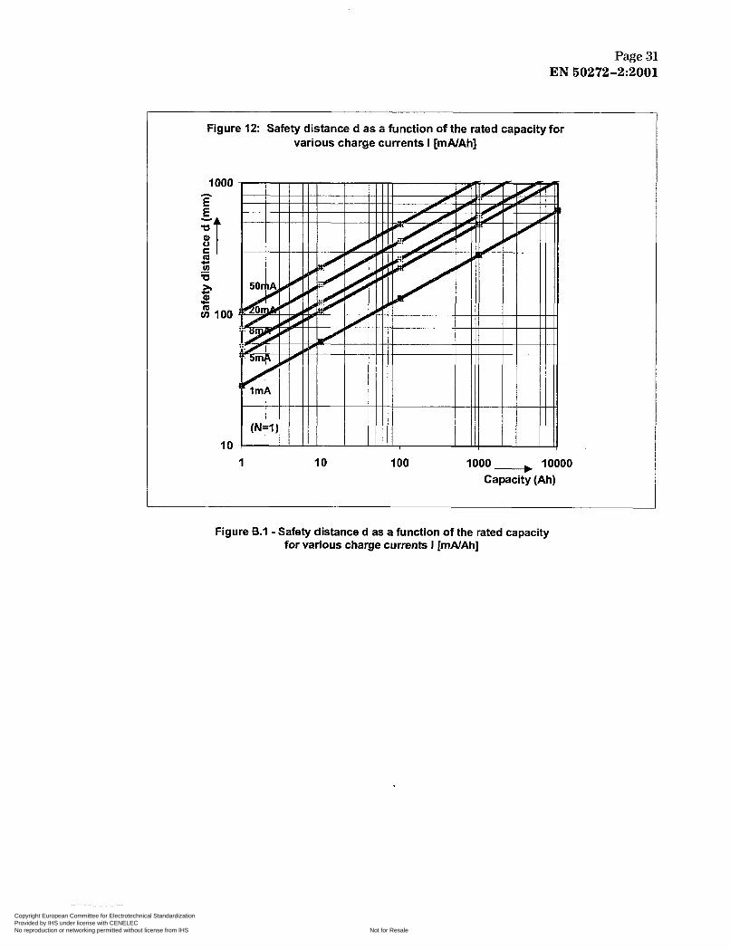
In the close vicinity of the battery the dilution of explosive gases is not always secured. Therefore a safety distance extending through air must be observed within which sparking or glowing devices (max. surface temperature 300 OC) are prohibited. The dispersion of explosive gas depends on the gas release rate and the ventilation close to the source of release. For calculation of the safety distance d from the source of release the following formula applies assuming a hemispherical dispersal of gas. The safety distance d can also be read from Figure B.I. For detailed information about the safety distance calculation see annex B.
8.7
Copyright European Committee for Electrotechnical Standardization Provided by IHS under license with CENELEC
Not for ResaleNo reproduction or networking permitted without license from IHS
--````-`-`,,`,,`,`,,`---

Page 19 EN 50272-2:2001
with: Igas = current producing gas (mA per Ah) Cfi = rated capacity (Ah)
NOTE The required safety distance d can be achieved by the use of a pamion wall between battery and sparking device.
Where batteries form an integral part of a power supply system, e.g. in a UPS system the safety distance d may be reduced according to the equipment manufacturers safety calculations or measurements. The level of air ventilation rate must ensure that a risk of explosion does not exist by keeping the hydrogen content in air below I%,, plus a safety margin at the potential ignition source.
Prevention of electrostatic discharges when working with batteries
Care shall be taken not to wear clothes and footwear which may build up electrostatic charge (see also 10.1 f)).
Absorbing cloth moistened only with water shall be used for battery cleaning. Other cleaning agents may result in built up of static charge or may damage the battery cases.
8.8
9 Provision against electrolyte hazard
9.1 Electrolyte and water
Electrolyte used in lead-acid batteries is an aqueous solution of sulphuric acid. Electrolyte used in NiCd batteries is an aqueous solution of potassium hydroxide. Distilled or demineralised water is used for topping up the cells.
9.2 Protective clothing
In order to avoid personal injury from electrolyte splashes when handling electrolyte' and/or vented cells or batteries, protective clothing shall be worn, such as
- protective glasses (see EN 166) or masks for eyes or face, - protective gloves and aprons for skin protection.
In the case of valve-regulated or gastight sealed batteries, a minimum of protective glasses and gloves shall be worn.
Accidental contact , "First Aid"
Both electrolytes create bums on eyes and skin. A source of water (tap or reservoir) shall be provided in the vicinity of the battery for cleaning away splashed electrolyte.
9.3
9.3.1 Eye contact
In the event of accidental contact with electrolyte immediately flood the eyes with large quantities of water for an extended period of time of at least 15 minutes. In all cases obtain immediate medical attention!
9.3.2 Skin contact
In the event of accidental contact with electrolyte wash the affected parts with large quantities of water or with neutralising aqueous solutions, such as soap water for sulphunc acid or a mild acidic solution for alkaline electrolyte. If irritation of skin persists obtain medical attention.
') Depending on the source of gas release the number of cells per monobloc battery (N) OT vent openings per cell (I/N) invdved must be
taken into consideration, ¡.e. by a factor of 6 , respectively .
Copyright European Committee for Electrotechnical Standardization Provided by IHS under license with CENELEC
Not for ResaleNo reproduction or networking permitted without license from IHS
--````-`-`,,`,,`,`,,`---
Page 20 EN 60272-2~2001
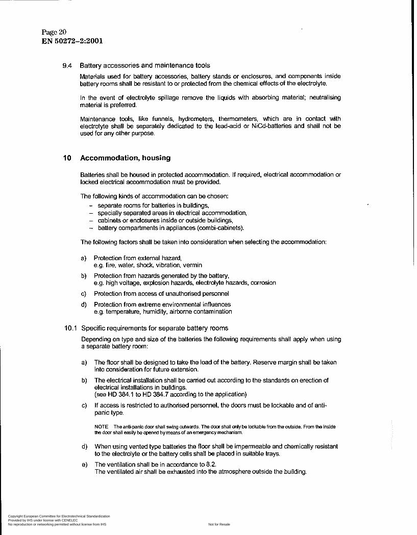
9.4
10
Battery accessories and maintenance tools Materials used for battery accessories, battery stands or enclosures. and components inside battery rooms shall be resistant to or protected from the chemical effects of the electrolyte.
In the event of electrolyte spillage remove the liquids with absorbing material; neutralising material is preferred.
Maintenance tools, like funnels, hydrometers, thermometers, which are in contact with electrolyte shall be separately dedicated to the lead-acid or NiCd-batteries and shall not be used for any other purpose.
Accommodation, housing
Batteries shall be housed in protected accommodation. If required, electrical accommodation or locked electrical accommodation must be provided.
The following kinds of accommodation can be chosen: - separate rooms for batteries in buildings, - specially separated areas in electrical accommodation, - cabinets or enclosures inside or outside buildings, - battery compartments in appliances (combi-cabinets).
The following factors shall be taken into consideration when selecting the accommodation:
a) Protection from extemal hazard, e.g. fire, water, shock, vibration, vermin
b) Protection from hazards generated by the battery, e.g. high voltage, explosion hazards, electrolyte hazards, corrosion
c) Protection from access of unauthorised personnel
d) Protection from extreme environmental influences e.g. temperature, humidiiy, airborne contamination
10.1 Specific requirements for separate battery rooms
Depending on type and size of the batteries the following requirements shall apply when using a separate battery room:
a) The floor shall be designed to take the load of the battery. Reserve margin shall be taken into concideration for future extension.
b) The electrical installation shall be carried out according to the standards on erection of electrical installations in buildings. (see HD 384.1 to HD 384.7 according to the application)
If access is restricted to authorised personnel, the doors must be lockable and of anti- panic type.
c)
NOTE The antiipanic door shall swing outwards. The door shall only be lockable from the outside. From the inside the door shall easiiy be opened by means of an emergency mechanism.
d) When using vented type batteries the floor shall be impermeable and chemically resistant to the electrolyte or the battery cells shall be placed in suitable trays.
e) The ventilation shall be in accordance to 8.2. The ventilated air shall be exhausted into the atmosphere outside the building.
Copyright European Committee for Electrotechnical Standardization Provided by IHS under license with CENELEC
Not for ResaleNo reproduction or networking permitted without license from IHS
--````-`-`,,`,,`,`,,`---

Page 21 EN 60272-2:2001
f) The floor area for a person standing within arm?s reach of the battery (see note 2) shall be electrostatic dissipative in order to prevent electrostatic charge generation. The resistance to a groundable point measured according to IEC 61340-4-1 shall be less than 10 MQ. Conversely the floor must offer sufficient resistance R for personnel safety. Therefore the resistance of the floor to a groundable point when measured in accordance with IEC 61340-4-1 shall be
for battery nominal voltage I 500 V:
for battery nominal voltage > 500 V:
5 0 k n I R 5 I O M Q
100 kn I R I 1 0 MQ
NOTE 1 To make the first part of the requirement f. effective. the personnel shall wear anti-static footwear when canying out maintenance work on the battery. The foohivear shall comply with EN 345.
NOTE 2 Arm?s reach: 1,25 m distance. (Definition of arm?s reach see HD 384.4.41 .)
10.2 Specific requirements for the specially separated areas in rooms accommodating electrical equipment
The requirements for the accommodation of batteries as described in 10.1 shall be fulfilled as well.
Additionally the following measures shall be taken:
a) Where a cell failure may cause spillage of electrolyte, the spillage must be contained e.g. by use of a retaining trays adequate to contain the electrolyte of at least one cell or monobloc.
Marking by waming and prohibiting signs according to 12.1 shall be fixed close to the battery.
Measures for protection against electric shock according to clause 5 and provision against explosion hazards according to clause 8 must be taken.
Also with central air conditioning in the building the ventilation requirements according to 8.2 shall be fulfilled. The minimum fresh air-supply shall correspond with the ventilation air flow Q.
b)
c)
d)
10.3 Battery enclosures
A battery enclosure may be selected for the following reasons: - to avoid routing cables from another battery location, - to provide a functionally complete item of equipment in one enclosure, - for protection against external hazards, - for protection from hazards generated by the battery, - for protection from access of unauthorised personnel, - for protection from external environmental influences.
10.3.1 Specific battery enclosure requirements
The following requirements shall apply when housing batteries in an enclosure: - Sufficient ventilation shall be provided to prevent the formation of an explosive hydrogen
concentration, see clause 8. - Precaution should be taken to prevent formation of an explosive concentration under
equipment fault conditions. see 8.6. - The floor (or shelf if fitted) shall be designed to take the load of the batteries. - Partitions within the enclosure will reduce the effective ventilation, and may increase the
temperature of the battery. This should be assessed during the design.
Copyright European Committee for Electrotechnical Standardization Provided by IHS under license with CENELEC
Not for ResaleNo reproduction or networking permitted without license from IHS
--````-`-`,,`,,`,`,,`---

Page 22 EN 50272-2:2001
- The distance between valve-regulated lead-acid cells or monobloc batteries shall be not less than 5 mm.
- The interior of the enclosure shall be chemically resistant to the electrolyte. - The enclosure shall prevent access to hazardous parts by anyone other than authorised
people. - The enclosure shall be designed to allow adequate access for maintenance using normal
tools.
10.4 Working on or near batteries
10.4.1 Working distances within battery rooms
To enable inspection, maintenance and changing of cells adequate working space is required.
To allow emergency evacuation an unobstructed escape path shall be maintained at all times with a minimum width of 600 mm.
NOTE 1 To allow temporary equipment to be placed in the access way, it is recommended that the escape path width is increased. The increased width may be based on the equipment which will be used, cf 1,5 times the width of the cell or 1 200 mm. i f no other information is available.
NOTE 2 For vdtages exceeding DC 120 V see 7.2.
10.4.2 Remarks on special work in battery rooms
Working on batteries or inside the safety distance (according to 8.7) with welding or soldering equipment, grinding machines or similar tools shall be carried out only by personnel who have been advised about the potential dangers. (Observe radius of flying sparks).
Before such work is carried out disconnect the batteries. Inflammable gas mixture inside vented cells or monobloc batteries shall be removed (blow out gas from the cells).
10.5 Accommodation of lead-acid and NiCd batteries in the same room
Ideally lead-acid and NiCd batteries shall be accommodated in separate rooms. Where both batteries are contained in the same room precautions shall be taken to avoid mixing of maintenance tools, electrolyte and topping up water.
1 I Charge current requirements
For charging methods and modes of operation refer to annex A.
11 .I Superimposed ripple current
Superimposed ripple current across the battery is generated by the charger and/or the load. When determining the ripple current interaction between the charger, battery, and load shall be taken into account, e.g. UPS-systems. The ripple current generates heat inside the cells and shall be kept as low as possible.
leff = effective alternating component of charge current (rms) n = integernumber k = number of harmonic frequencies In
At all times the DC component of the float charge current shall have a positive value and be within the typical range of 0,l mA to 1,0 mA per i Ah rated capacity.
= effective alternating currents (ac) at each harmonic frequency (rms) (Fourier-Analysis)
Copyright European Committee for Electrotechnical Standardization Provided by IHS under license with CENELEC
Not for ResaleNo reproduction or networking permitted without license from IHS
--````-`-`,,`,,`,`,,`---

Page 23 EN 60272-2:2001
leff
float charge
boost chame
11.2 Maximum ripple current
Under float charge and boost charge conditions, it is recommended that the superimposed effective alternating component of the charge current l~ (rms) is limited to the values specified in Table 2.
Lead-acid batteries NiCd batteries
5 A 20 A
10 A 20 A
The effective current leff is measured with a clamp-on ammeter.
Table 2 - Recommended limits of current lefi per IOOAh rated capacity through the battery
Higher values of ripple current will effect the gas generation and the battery life of lead-acid batteries and therefore leff shall be limited to 10 A per 100 Ah for floating operation and to 20 A per 100 Ah during temporary charge operations.
12 Identification labels, warning notices and instructions for use, installation and maintenance
12.1 Warning labels and notices
The following waming labels or notices shall identify a battery room and be displayed outside:
- "Dangerous voltage", if the battery voltage is > DC 60 V, see IS0 3864; - Prohibition sign for "Fire, naked flames, smoking prohibited; - Warning sign "Accumulator, Battery Room" to indicate corrosive electrolyte, explosive
gases, dangerous voltages and currents.
12.2 Identification labels or marking
The identification label or marking shall be durably fixed on each cell, monobloc battery or battery assembly unit and shall include the information as required by the standards EN 60896-1, EN 60896-2 and EN 60623 dealing with the relevant battery types.
It is recommended that each cell, monobloc battery or battery assembly unit can be easily identified for maintenance purposes, e.g. by using cell and battery numbers.
12.3 Instructions for use, installation and maintenance
The following instructions shall be supplied with the battery delivery and shall be displayed in the vicinity of the battery:
Name of manufacturer or supplier, Manufacturer's or supplier's type reference, Nominal battery voltage, Nominal or rated capacity of the battery including relevant ratings, Name of installer, Date of commissioning, Statements of safety recommendations, operation and maintenance, Information regarding disposal and recyding.
The instnictions shall be accessible to the maintenance and operation personnel.
Copyright European Committee for Electrotechnical Standardization Provided by IHS under license with CENELEC
Not for ResaleNo reproduction or networking permitted without license from IHS
--````-`-`,,`,,`,`,,`---

Page 24 EN 50272-2~2001
13
13.1 Packing and transport
Transportation, storage, disposai and environmental aspects
The packing and transport of secondary batteries is covered in various national and international regulations. The following international regulations for transport, safe packing and carriage of dangerous goods apply:
Road: European Agreement for the International Carriage of Dangerous Goods by Road (ADR)
International Convention concerning the carriage of Goods by Rail (CIM) Annex A: International regulations concerning the carriage of dangerous goods by rail
International Maritime Organisation, Dangerous Goods Code IMDG Code 8 Class 8 corrosive
International Air Transport Association (IATA), Dangerous Goods Regulations (30th Edition, Ist January 1989, resp. current edition)
Rail (intemational):
(RID) Sea:
Air:
13.2 Dismantling, disposal, and recycling of batteries
Dismantling and disposal of stationary batteries shall be undertaken by competent personnel only.
The following EC Directives must be followed: - 91/157/EEC (Council directive)
- 93/86/EEC (Commission directive) "Batteries and accumulators containing certain dangerous substances".
"Adaptation to technical progress of Council Directive 91/157/EEC".
National regulations may also apply.
14 Inspection and monitoring For functional and safety reasons regular inspection of the battery and its operating environment is required.
In accordance with the manufacturer's requirements the inspection should include a check of, e.g.:
- voltage setting on the charger; - cell or monobloc battery voltages; - specific gravity (SG) and electrolyte level, if appropriate; - cleanliness, leakage; - tightness of connectors, if required; - ventilation; - vent plugs or valves; - battery temperature.
If a capacity test is carried out the following methods of test apply: lead-acid battery, vented type EN 60896-1, clause 13 lead-acid battery, valve regulated type : EN 60896-2, clause 18 NiCd battery, vented type EN 60623, clause 4.2
If automatic monitoring is used the recommendations in the guideline (draft for stationary lead- acid batteries under development in I ECnC 21) should be followed.
Copyright European Committee for Electrotechnical Standardization Provided by IHS under license with CENELEC
Not for ResaleNo reproduction or networking permitted without license from IHS
--````-`-`,,`,,`,`,,`---

Page 25 EN 50272-2:2001
Battery type Voltage range
Vlcell Typical values
ViceIl
A. 1
Pb NiCd 2,18-2,35 1,36-1,45
2,23 up to 2,30 ') 1,40
Annex A (informative)
Charging methods, Modes of operation
Parallel operation mode
The parallel operation mode provides a continuous power supply without interruption to the load.
charger load
- battery T
Figure A.l - Principal circuit for parallel operation mode
A.l .I Battery "stand by" operation mode
The battery "stand by" operation mode is characterised by permanent charge at the float charge conditions. Applicable float charge voltages see Table A.1.
Table A.1 - Float charge voltages for lead-acid and NiCd batteries
Typical charge current of a battery under recharge is shown in Figures A.2 and A.3.
I I J I
-;t/ms
Figure A.2 - The charger supplies the full current to the load and to the battery
Figure A3 - Magnified battery charge with superimposed ripple current
Copyright European Committee for Electrotechnical Standardization Provided by IHS under license with CENELEC
Not for ResaleNo reproduction or networking permitted without license from IHS
--````-`-`,,`,,`,`,,`---

Page 26 EN 60272-2~2001
The charger is able to supply at any time all current to the load and to the battery (incl. recharge current).
Typical float charge current with slight peak discharges is shown in Figures A.4 and A.5.
-Vms
Figure A.4 - The charger supplies the full current to the load and to the battery
Figure A5 - Magnified battery float charge with superimposed ripple current
The charger is able to supply on average all current to the load and to the battery (incl. recharge current, see Figure A.4). Compared to the load current the float charge current is normally very low.
NOTE The majority of UPSsystems consist of parallel operating charger. battery, and inverter. The battery k permanently charged according to the stand-by operation mode.
A.1.2 Buffer operation mode
The buffer operation mode is characterised by a continuous charge using charging voltages to hold the battery in approximately fully charged condition.
The battery is not charged at all times. The load may temporarily exceed the rated current of the charger or the battery may be discharged caused by power limitations of the source.
i1p.I battery , charge current
Figure A.6 - The charger does not supply the full current to the load and to the
battery
Figure A.7 - Magnified battery charge current w frequent temporary discharge load current
To compensate for battery capacity losses, regular boost charge or charging at permanently higher voltage is required.
NOTE The expected senke life of the battery may be reduced.
Copyright European Committee for Electrotechnical Standardization Provided by IHS under license with CENELEC
Not for ResaleNo reproduction or networking permitted without license from IHS
--````-`-`,,`,,`,`,,`---

Page 27 EN 50272-2:2001
A.1.3 Shallow cycling operation mode
The shallow cycling operation mode is charactensed by small discharges of the battery in cydes of certain frequency. The expected service life is mainly determined by the number and depth of the discharge cycles.
A.2 Response mode operation I n m-1 ' I d '
7 battery charger
I
Figure A.8 - Response mode operation
On the occurrence of power failure the load is connected to the battery power source. This can be done with or without interruption.
A.3 Charging methods Charging methods to be used shall recharge batteries within the time specified by the application.
Three basic characteristics are available
a) constant current charge I
b) constant voltage charge U
c) constant resistance charge R (taper charge)
Also combinations of these characteristics are possible.
A typical charging characteristic is the IU-characteristic with current limitation during the beginning of the recharge until the voltage has reached the pre-set level followed by the constant voltage charge at the float charge voltage level (see Figures A.9 and A.lO).
- 1 -t
Figure A.9 - IU charge characteristic Figure A.10 - Time dependant characteristic of current I and voltage U
To reduce the time it takes to recharge the battery to full capacity a two-voltage level charge is used (IUqU2). In the first step the voltage is limited to the boost charge voltage (U1) followed by the second step at the float charge level (U2).
Copyright European Committee for Electrotechnical Standardization Provided by IHS under license with CENELEC
Not for ResaleNo reproduction or networking permitted without license from IHS
--````-`-`,,`,,`,`,,`---

Page 28 EN 50272-2:2001
Lead-acid batteries vented cells
U1 boost 2,33 - 2.45 V/cell
Table A.2 -Typical voltage levels at 20°C
Lead-acid batteries NiCd batteries VRLA cells vented cells 2.40 V/cell 1.40 - 1,65 V/cell
u 2 I float I 2,18 - 2,25 V/cell I 2,23 - 2.30 V/cell I 1,36 - 1,45 V/cell I If recharge takes place with U1 occasionally only (¡.e. monthly) refer to the float charge current in 8.2, when calculating the ventilation air flow.
A.4 Temperature compensation of the charge voltage
Temperature compensation of the charge voltage may be beneficial where the battery temperature deviates from 20°C. For further information the battery manufacturer shall be consulted.
Copyright European Committee for Electrotechnical Standardization Provided by IHS under license with CENELEC
Not for ResaleNo reproduction or networking permitted without license from IHS
--````-`-`,,`,,`,`,,`---

Page 29 EN 50272-2:2001
Annex B (informative)
Calculation of safety dfictance d to protect against explosion hazards
In close vicinity to the source of release of a cell or battery the dilution of explosive gases is not always ensured. Therefore a safety distance d extending through air must be observed within which flames, sparks, arcs or glowing devices (max. surface temperature 300°C) are prohibited. The dispersion of explosive gas depends on the gas release rate and the ventilation characteristics close to the source of release.
The minimum safety distance d can be estimated by calculating the dimensions of a hypothetical volume V, of potentially explosive gas around the source of release, where the concentration of hydrogen is below the safe concentration of the lower explosion limit (LEL).
B.l Estimation of hypothetical volume V,
The theoretical minimum ventilation flow rate to dilute the flammable gas (hydrogen) to a concentration below the lower explosion limit (LEL) can be calculated by means of the formula:
where:
dV/dtmin = minimum volumetric flow rate of fresh air required to dilute the gas [m3/s] dG/dtmax = maximum gas release rate [kg/s] LEL = lower explosion limit (4 for hydrogen) [kg/m3] k T
= safety factor applied to the LEL ; k = 0,25 is chosen for dilution of hydrogen gas, = ambient temperature (293 Kelvin = 20 "C) [KI
The volume V, represents the volume over which the mean concentration of flammable gas will be 0,25 times the LEL. This means that at the extremities of the hypothetical volume, the concentration of gas will be significantly below the LEL, ¡.e. the hypothetical volume where the concentration is above LEL would be less than V,
8.2 Correction factors
With a given number of air changes per unit time, c. related to the general ventilation the hypothetical volume V, of potentially explosive atmosphere around the source of release can be estimated as followc:
where c = number of fresh air changes per unit time [s-'1.
Copyright European Committee for Electrotechnical Standardization Provided by IHS under license with CENELEC
Not for ResaleNo reproduction or networking permitted without license from IHS
--````-`-`,,`,,`,`,,`---

Page 30 EN 50272-2~2001
The above formula holds for an instantaneous and homogenous mixing at the source of release given ideal flow conditions of fresh air. In practice, ideal conditions rarely exist. Therefore a correction factor f is introduced to denote the effectiveness of the ventilation.
v2= f .
where f = ventilation effectiveness factor, denoting the efficiency of the ventilation in terms of its effectiveness in diluting the explosive atmosphere, f ranging from 1 (ideal) to typicaliy 5 (impeded air flow). For battery installations the ventilation effectiveness factor is f = 1.25.
B.3 Calculation of safety distance d
The term (:)min including all safety factors corresponds with the hourly ventilation air flow Q
(in m3/h) for secondary batteries calculated under 8.2.
dV dt
Q = f . -
Q = 0,05 (N)? 19s Crt 103 [m3/h]
This hourly ventilation air flow Q can be used to define a hypothetical volume. Assuming a hemispherical dispersal of gas a volume of a hemisphere V, = 2/3 7c d3 can be defined, where d is the safety distance from the source of release.
This results in the calculation formula for the safety distance d, with c = 1 air change per h within the hemisphere:
d3=&. o . o ~ . I o ~ . ( N ) . I ~ ~ ~ - c ~ ~ [mm317
*) Depending on the source of gas release the number of cells per monobloc battery ( N ) or vent openings per cell invotved (I/N) must be taken into consideration, i. e. by the factor 6, respectively % .
Copyright European Committee for Electrotechnical Standardization Provided by IHS under license with CENELEC
Not for ResaleNo reproduction or networking permitted without license from IHS
--````-`-`,,`,,`,`,,`---
Page 31 EN 50272-2:2001
Figure 12: Safety distance d as a function OP the rated capacityfor
1 O00 h
E
it o C
m u) U 5r
CI .- U L G I00
10
various charge currents I [mNAh]
1 10 I O0 1000 1 O000 Capacity (Ah)
Figure 6.1 - Safety distance d as a function of the rated capacity for various charge currents I [mAiAh]
Copyright European Committee for Electrotechnical Standardization Provided by IHS under license with CENELEC
Not for ResaleNo reproduction or networking permitted without license from IHS
--````-`-`,,`,,`,`,,`---

BS EN 50272-2:2001
BSI 389 Chiswick High Road London w 4 4AL
BSI - British Standards Institution BSI is the independent national body responsible for preparing British Standards. It presents the UK view on standards in Europe and a t the nternational level. It is incorporated by Royal Charter.
Revisions
British Standards are updated by amendment or revision. Users of British Standards should make sure that they possess the latest amendments or ?ditionS.
[t is the constant aim of BSI to improve the quality of our products and services. We would be grateful if anyone finding an inaccuracy or ambiguity while using :his British Standard would inform the Secretary of the technical committee responsible, the identity of which can be found on the inside front cover. Tel: 020 8996 9000. Fax: 020 8996 7400.
BSI offers members a n individual updating service called PLUS which ensures that subscribers automatically receive the latest editions of standards.
Buying standards
Orders for all' BSI, international and foreign standards publications should be addressed to Customer Services. Tel: O20 8996 9001. Fax: 020 8996 7001. Standards are also available from the BSI website a t htti,://www.bsi-dobal.coxn.
in response to orders for international standards, it is BSI policy to supply the BSI implementation of those that have been published a s British Standards, unless otherwise requested.
Information on standards
BSI provides a wide range of information on national, European and international standards through its Library and its Technical Help to Exporters Service. Various BSI electronic information services are also available which give details on all its products and services. Contact the Information Centre. Tel: 020 8996 7111. Fax: 020 8996 7048.
Subscribing members of BSI are kept up to date with standards developments and receive substantial discounts on the purchase price of standards. For details of these and other benefits contact Membership Administration. Tel: 020 8996 7002. Fax: 020 8996 7001. Further information about BSI is available on the BSI website at htto://www.bsi-g-.
Copyright
Copyright subsists in all BSI publications. BSI also holds the copyright, in the UK, of the publications of the international standardization bodies. Except as permitted under the Copyright, Designs and Patents Act 1988 no extract may be reproduced, stored in a retrieval system or transmitted in any form or by any means - electronic, photocopying, recording or otherwise - without prior written permission from BSI.
This does not preclude the free use, in the course of implementing the standard, of necessary details such as symbols, and size, type or grade designations. If these details are to be used for any other purpose than implementation then the prior written permission of BSI must be obtained.
If permission is granted, the terms may include royalty payments or a licensing agreement. Details and advice can be obtained from the Copyright Manager. Tel: 020 8996 7070.
Copyright European Committee for Electrotechnical Standardization Provided by IHS under license with CENELEC
Not for ResaleNo reproduction or networking permitted without license from IHS
--````-`-`,,`,,`,`,,`---