catalog d31.2 • october 2021 – sinamics g115d distributed
TRANSCRIPT

7.1/18 Siemens D 31.2 · October 2021
SINAMICS G115D distributed drive system • System overview0.37 kW to 7.5 kW
Configuring guide • Determining the drive data
71
■ Overview
General configuring notes are provided for the standard versions in this catalog.
SIMOGEAR geared motors permit individual solutions to be created for a wide range of drive applications. In order to select the correct drive, initially specific data for the application must be known or determined.
For drives operating under special conditions, e.g. frequent reversing, short-time or intermittent duty, abnormal tempera-tures, reversal braking, extreme cantilever forces at the gearbox output shaft, etc. please contact your Siemens contact person with all of your technical questions.
You will find additional information on our internet site at www.siemens.com/geared-motors
The flow diagram illustrates the process for selecting and dimensioning a geared motor using a traction drive as an example. However, the specific requirements and boundary conditions associated with the application in question must always be taken into account.
Load properties Load cycle Environmental/operating conditions (Mounting, weight, number of starting
operations, operating period) (Travel velocity, gradient, friction,
travel route)(Temperature, installation altitude,
load classification)
Calculation of the application data
• Speeds, torques• Transmissino ratio• Static and dynamic power Preq
Motor selection
• Operating data (voltage, frequency, efficiency class, temperature class, regional regulations)
• Duty type (converter operation)• System performance (Preq PN)
Brake selection
• Operating data (brake torque, type, control)• Calculating the braking time and braking distance• Calculating the switching frequency and service life
Gearbox selection
• Gearbox size (fB tot fB gearbox) and gearbox type• Transmission ratio• Defining the mounting position of the geared motor and the
position of the terminal box
Geared motor check
• Application requirements and dataNew selection Larger motor NO YES
Selecting additional gearbox and motor options
• Gearbox equipping (shaft dimensions, sealing system, oil)• Motor options (motor protection, encoders, connector
systems, terminal box position)
Gearbox check
• Axial and cantilever forces, bearing life and thermal stress
New selection
YES NO Larger gearbox
Supplement Article No.
© Siemens 2021

7.1/19Siemens D 31.2 · October 2021
SINAMICS G115D distributed drive system • System overview0.37 kW to 7.5 kW
Configuring guide • Determining the drive data
71
■ Overview
Supplement Article No.
Converter operation
• Selection of the power unit according to the base-load current• Selection of the power unit according to the overload current• Static and dynamic power
DC link components• Selection of a braking resistor for occurring regenerative
energy
Cables• Power cables with and without connection option
Done
© Siemens 2021

7.1/20 Siemens D 31.2 · October 2021
SINAMICS G115D distributed drive system • System overview0.37 kW to 7.5 kW
Configuring guide • Configuring a gearbox
71
■ Overview
Standards
Calculation to AGMA available on request.
Gearbox efficiency
The efficiency of the gearbox is determined in part by the gear teeth, the rolling bearing friction, and the shaft seal friction.
Helical, parallel shaft and bevel gearboxes
SIMOGEAR helical, parallel shaft, and bevel geared motors have a very high efficiency. Generally, efficiencies of 96 % (2-stage) and 94 % (3-stage) can be assumed. These gearbox types can be operated with energy-efficient motors to create an excellent solution.
Helical worm gearboxes
The first stage of the helical worm gearbox is designed as a he-lical stage. With the optimally tuned transmission ratios of the worm stage, the best possible overall efficiency is achieved, which is considerably higher than that of worm gearboxes alone.
Precise efficiency data can be found in the tables in chapter "Helical worm gearboxes".
Owing to the high degrees of efficiency, the SIMOGEAR helical worm gearboxes are not self-locking.• Running-in period
The tooth flanks on new helical worm gearboxes will not yet be fully smoothed, meaning that the friction angle will be greater and efficiency lower during the running-in period. The higher the transmission ratio, the more pronounced the effect.The running-in process should take approximately 24 hours of operation at full load. In most cases, the catalog values will then be reached.
Efficiency optimization
As a result of the large range of transmission ratios, in many cases, instead of a 3-stage gearbox, a 2-stage SIMOGEAR gearbox can be used.
This means that the efficiency is improved by approximately 2 % when compared to conventional drives.
Further, the efficiency can be improved by optimizing the mount-ing position and the input speed.
Splashing losses
For certain gearbox constructions, the first stage can be com-pletely immersed in the gearbox oil. In the case of large gear-boxes with a high input speed, particularly with vertical mount-ing positions, this may lead to increased splashing losses, which cannot be neglected.
If you wish to use gearboxes such as these, then please contact Siemens. If at all possible, you should choose horizontal types of construction in order to keep splashing losses to a minimum.
DIN/ISO
DIN 743 Output shafts
ISO 281, ISO 76 Bearings
DIN 7190 Press-fit connection
DIN 6892 Parallel key connection
DIN 3990 Cylindrical gear toothing
DIN 3991 Bevel gear toothing
DIN 3996 Worm gear toothing
© Siemens 2021

7.1/21Siemens D 31.2 · October 2021
SINAMICS G115D distributed drive system • System overview0.37 kW to 7.5 kW
Configuring guide • Configuring a gearbox
71
■ Overview
Service factor
The service factor fB is a safety factor for the gearboxes that takes the operating conditions of the drive into account.
The following applies to selecting a suitable drive:
fB fBreq
The gearbox size or rated gearbox torque and the resulting service factor are not standardized and depend on the manu-facturer.
Service factor (fB)
The service factor is calculated from the drive data you selected and can be obtained from the DT Configurator.
Determining the required service factor (fBreq)
In standard operation, i.e. with a uniform load provided by the driven machine, small masses to be accelerated, and a low number of switching operations, the service factor of fBreq = 1 can be selected.
For operating conditions that deviate from this, the required service factor must be calculated with the following formulas.• For helical, parallel shaft and bevel gearboxes
fBreq = fB1· fBT
• For helical worm gearboxes
fBreq = fB1· fB2 · fBT
Determining the service factor driven machine (fB1)
The service factor of the driven machine fB1 is determined from the load classification, switching frequency, and operating period per day.• Load groups of driven machines
Mass acceleration factor (mBF)
The mass acceleration factor mBF is calculated as follows:
All external moments of inertia are moments of inertia of the driven machine and the gearbox, which are to be reduced to the motor speed.
The calculation is made using the following formula:
In most cases the relatively insignificant moment of inertia of the gearbox can be ignored. The mass acceleration factor mBF is calculated as follows with reference to the gearbox and the adapter:
Service factor fB1
Load classifi-cation
Mass accelera-tion factor (mBF)
Driven machine (examples)
IAlmost shock-free
0.3 Electric generators, belt conveyors, apron conveyors, screw conveyors, light-weight elevators, electric hoists, machine tool feed drives, turbo blowers, centrifu-gal compressors, mixers and agitators when mixing materials with uniform density
IIModerate shock loads
3 Machine tool main drives, heavy elevators, slewing gear, cranes, shaft ventilators, mixers and agitators when mixing materials with non-uniform densities, reciprocating pumps with multi-ple cylinders, metering pumps
IIIHeavy shock loads
10 Punching presses, shears, rubber knead-ers, machinery used in rolling mills and the iron and steel industry, mechanical shovels, heavy centrifuges, heavyweight metering pumps, rotary drilling rigs, briquetting presses, pug mills
Code Description Unit
fB Service factor -
fB1 Service factor driven machine -
fB2 Service factor short-time duty -
fBreq Required service factor -
fBT Service factor ambient temperature -
i Transmission ratio -
J2 Moment of inertia of the load referred to the output speed of the gearbox
kgm²
JAD Moment of inertia of the adapter referred to the input speed
kgm²
JB Moment of inertia of the brake kgm²
JG Moment of inertia of the gearbox referred to the input speed
kgm²
Jmot Moment of inertia of the motor kgm²
JX Moment of inertia of the load referred to the input speed
kgm²
mBF Mass acceleration factor -
n1 Input speed of the gearbox rpm
n2 Output speed of the gearbox rpm
mBF
Jx
Jmot JB+ -----------------------------=
JX J2
n2
n1------
2 J2
i 2---------==
mBF
Jx JG J+ AD+
Jmot JB+ ------------------------------------=
G_D
087_
EN
_001
56
1.5
1.4
1.6
1.7
1.3
1.2
1.1
1.0
1.7
1.6
1.8
1.5
1.4
1.3
1.2
1.5
1.4
1.6
24 h 16 h 8 h
1.3
1.2
1.1
1.0
0.9
0.8
Operating period per day
Switching frequency per hour
Load classification III
Load classification II
Load classification I
Serv
ice
fact
or f B
1
1500125010007505002500
© Siemens 2021

7.1/22 Siemens D 31.2 · October 2021
SINAMICS G115D distributed drive system • System overview0.37 kW to 7.5 kW
Configuring guide • Configuring a gearbox
71
■ Overview
Determining the service factor ambient temperature (fBT)
If the drive warms up to an operating temperature above -20 °C at max. 70 % load, fBT =1 can be set.• For helical, parallel shaft and bevel gearboxes
Service factor ambient temperature
• For helical worm gearboxes
Service factor ambient temperature for helical worm gearboxes
Determining the service factor short-time duty (fB2)• For helical worm gearboxes
Service factor short-time duty
Note:
When selecting and dimensioning drives with the following special application conditions, please contact Siemens.• Frequent reversing• Short time and intermittent operation• Abnormal temperatures• Reversal braking• Extreme and/or circulating radial forces at the gearbox output
shaft• Fluctuating loads
[°C]amb
0.8
0.9
1.0
1.1
1.2
1.3
1.4
1.5
1.6
1.7
1.8
1.9
2.0
G_M
015_
EN_0
0242
fBT
0 10-10-20-30-40 20 30 40 50 60
[°C]amb
0.8
0.9
1.0
1.1
1.2
1.3
1.4
1.5
1.6
1.7
1.8
1.9
2.0
G_M
015_
EN_0
0241
fBT
0 10-10-20-30-40 20 30 40 50 60
1.0
0.9
0.8
0.7
0.6
0.5
G_M
015_
EN_0
0032
DC [%]
fB2
0 10 20 30 40 50 60 70 80 90 100
© Siemens 2021
7.1/23Siemens D 31.2 · October 2021
SINAMICS G115D distributed drive system • System overview0.37 kW to 7.5 kW
Configuring guide • Configuring a gearbox
71
■ Overview
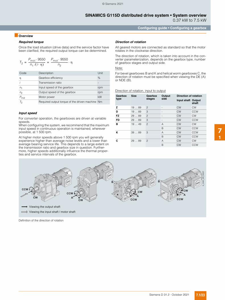
Required torque
Once the load situation (drive data) and the service factor have been clarified, the required output torque can be determined.
Input speed
For converter operation, the gearboxes are driven at variable speeds. When configuring the system, we recommend that the maximum input speed in continuous operation is maintained, wherever possible, at 1 500 rpm.
At higher motor speeds above 1 500 rpm you will generally experience higher than average noise levels and a lower than average bearing service life. This depends to a large extent on the transmission ratio and gearbox size in question. Further-more, higher speeds additionally influence the thermal proper-ties and service intervals of the gearbox.
Direction of rotation
All geared motors are connected as standard so that the motor rotates in the clockwise direction.
The direction of rotation, which is taken into account in the con-verter parameterization, depends on the gearbox type, number of gearbox stages and output side.
Note:
For bevel gearboxes B and K and helical worm gearboxes C, the direction of rotation must be specified when viewing the DE (A) or NDE (B).
Direction of rotation, input to output
Definition of the direction of rotation
Code Description Unit
Gearbox efficiency %
i Transmission ratio -
n1 Input speed of the gearbox rpm
n2 Output speed of the gearbox rpm
Pmot Motor power kW
T2 Required output torque of the driven machine Nm
T2
Pmot 9550n1 i
------------------------------Pmot 9550
n2------------------------------ = =
Gearbox type
Size Gearbox stages
Output side
Direction of rotation
Input shaft Output shaft
Z 19 … 89 2 - CW CW
D 19 … 89 3 - CW CCW
FZ 29 … 89 2 - CW CW
FD 29 … 89 3 - CW CCW
B 19 … 49 2 A CW CW
B CW CCW
K 39 … 89 3 A CW CCW
B CW CCW
C 29 … 89 2 A CW CW
B CW CCW
CCW
CW
B
A
B
A
Viewing the output shaft
Viewing the input shaft / motor shaft
G_D
087_
EN
_002
07
ACCW
CW
CCW
CWCCW
CW
© Siemens 2021
7.1/24 Siemens D 31.2 · October 2021
SINAMICS G115D distributed drive system • System overview0.37 kW to 7.5 kW
Configuring guide • Configuring a gearbox
71
■ Overview
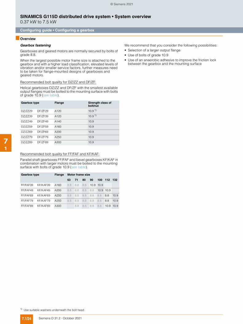
Gearbox fastening
Gearboxes and geared motors are normally secured by bolts of grade 8.8.
When the largest possible motor frame size is attached to the gearbox and with a higher load classification, elevated levels of vibration and/or smaller service factors, further measures need to be taken for flange-mounted designs of gearboxes and geared motors.
We recommend that you consider the following possibilities:• Selection of a larger output flange• Use of bolts of grade 10.9• Use of an anaerobic adhesive to improve the friction lock
between the gearbox and the mounting surface
Recommended bolt quality for DZ/ZZ and DF/ZF:
Helical gearboxes DZ/ZZ and DF/ZF with the smallest available output flanges must be bolted to the mounting surface with bolts of grade 10.9 (see table).
Recommended bolt quality for FF/FAF and KF/KAF:
Parallel shaft gearboxes FF/FAF and bevel gearboxes KF/KAF in combination with larger motors must be bolted to the mounting surface with bolts of grade 10.9 (see table).
Gearbox type Flange Strength class of bolt/nut
DZ/ZZ29 DF/ZF29 A120 10.9 1)
DZ/ZZ39 DF/ZF39 A120 10.9 1)
DZ/ZZ49 DF/ZF49 A140 10.9
DZ/ZZ59 DF/ZF59 A160 10.9
DZ/ZZ69 DF/ZF69 A200 10.9
DZ/ZZ79 DF/ZF79 A250 10.9
DZ/ZZ89 DF/ZF89 A300 10.9
Gearbox type Flange Motor frame size
63 71 80 90 100 112 132
FF/FAF39 KF/KAF39 A160 8.8 8.8 8.8 10.9 10.9
FF/FAF49 KF/KAF49 A200 8.8 8.8 8.8 8.8 10.9 10.9
FF/FAF69 KF/KAF69 A250 8.8 8.8 8.8 8.8 8.8 8.8 10.9
FF/FAF79 KF/KAF79 A250 8.8 8.8 8.8 8.8 8.8 8.8 10.9
FF/FAF89 KF/KAF89 A300 8.8 8.8 8.8 8.8 10.9 10.9
1) Use suitable washers underneath the bolt head.
© Siemens 2021

7.1/25Siemens D 31.2 · October 2021
SINAMICS G115D distributed drive system • System overview0.37 kW to 7.5 kW
Configuring guide • Configuring a gearbox
71
■ Overview
Shaft load and bearing service life
Available radial force
The radial forces either come from the driven machine (mixer, hoisting gear) or they are caused by the transmission elements.
The available radial force FRavail at the output shaft is obtained as follows:• The required geared motor output torque T2• Average diameter of the mounted transmission element d0• Transmission element type, e.g. chain wheel
The transmission element type determines the additional factor C (see table).
The ambient temperature determines the additional factor T.
Additional factor C for the transmission element type
Additional factor T for ambient temperature
Permissible radial force
The permissible radial force FR2 is determined by the required bearing service life, among other things. The nominal service life Lh10 is determined in accordance with ISO 281. Normally, calcu-lating the nominal bearing service life is completely adequate.
The bearing service life can be calculated for special operating conditions and in special cases on request, based on the modi-fied service life Lna.
The selection tables specify the permissible radial force FR2 for the output shafts of foot-mounted gearboxes with solid shaft "1" (For further information and order codes see Gearbox options). These table values refer to the force application point at the cen-ter of the shaft extension and are minimum values, which apply under the most unfavorable conditions (force application angle, mounting position, direction of rotation).
If the values in the table are not sufficient, or if other gearbox designs are being used, please contact Siemens.
Permissible axial force
If no radial force is present, then max. 50 % of the permissible radial force can be applied as a permissible axial force Fax (tension or compression).
Higher permissible radial and axial forces
The permissible radial force load can be increased, taking the force application angle and the direction of rotation into account. Installing reinforced bearings also means that higher loads are permitted on the output shaft.
If higher radial or axial forces or combined loads comprising radial and axial forces occur, then please contact Siemens.
Note:
Bevel gearboxes B and K and helical worm gearboxes C in type of construction M1 with foot mounting on the face side: A maximum of 50 % of the radial force FR2 specified in the tables is permissible.
Helical geared motors ZB and DB in foot/flange-mounted designs: When transmitting torque through the flange surface, a maxi-mum of 50 % of the radial force FR2 specified in the tables is permissible.• Variables for defining shaft load and bearing service life
Transmission element Explanation Additional factor C
Gear wheel > 17 teeth 1.00
17 teeth 1.15
Chain wheel 20 teeth 1.00
14 ... 19 teeth 1.25
13 teeth 1.40
Toothed belts Preloading force 1.50
V-belts Preloading force 2.00
Flat belts Preloading force 2.50
Agitator/mixer Rotating radial force 2.50
Temperature range Low-temperature factor T
-20 °C ... +60 °C 1.0
-21 °C ... -40 °C 1.5
FRavail 2000T2
d0------ C T =
Code Description Unit
Force application angle °
a Gearbox constant kNmm
b, d, l, y, z Gearbox constants mm
C Additional factor to calculate the radial force -
d0 Average diameter of the mounted transmission element
mm
Fax Permissible axial force N
Fx Permissible radial force from out of center force application point
N
Fxperm1 Permissible radial force, limited by the bear-ing service life, at a distance of x from the shaft shoulder
N
Fxperm2 Permissible radial force, limited by the shaft strength, at a distance of x from the shaft shoulder
N
FRavail Available radial force from the mounted trans-mission element
N
FR2 Permissible radial force at the center of shaft extension (l/2)
N
Lh10 Nominal service life h
Lna Modified service life h
T Additional factor for ambient temperature -
T2 Geared motor output torque Nm
x Distance from the shaft shoulder up to the point where force is applied
mm
© Siemens 2021
7.1/26 Siemens D 31.2 · October 2021
SINAMICS G115D distributed drive system • System overview0.37 kW to 7.5 kW
Configuring guide • Configuring a gearbox
71
■ Overview
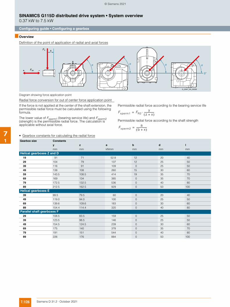
Definition of the point of application of radial and axial forces
Diagram showing force application point
Radial force conversion for out of center force application point
If the force is not applied at the center of the shaft extension, the permissible radial force must be calculated using the following formula.
The lower value of Fxperm1 (bearing service life) and Fxperm2 (strength) is the permissible radial force. The calculation is applicable without axial force.
Permissible radial force according to the bearing service life
Permissible radial force according to the shaft strength
• Gearbox constants for calculating the radial force
G_D041_XX_00338
x
α α αα
0°
Fx
Fax
Fxperm1 FR2y
z x+ -----------------=
Fxperm2a
b x+ ------------------=
Gearbox size Constants
y z a b d l
mm mm kNmm mm mm mm
Helical gearboxes Z and D19 91 71 52.8 12 20 40
29 104 79 137 12 25 50
39 116 91 109 0 25 50
49 138 108 260 15 30 60
59 143.5 108.5 414 19 35 70
69 169 134 385 0 35 70
79 172.5 132.5 536 0 40 80
89 212.5 162.5 929 0 50 100
Helical gearboxes E39 99.5 79.5 60 0 20 40
49 119.0 94.0 100 0 25 50
69 139.6 109.6 183 0 30 60
89 154.4 114.4 320 0 40 80
Parallel shaft gearboxes F29 108.5 83.5 159 0 25 50
39 123.5 98.5 146 0 25 50
49 154.5 124.5 239 0 30 60
69 175 140 378 0 35 70
79 191 151 544 0 40 80
89 226 176 884 0 50 100
© Siemens 2021
7.1/27Siemens D 31.2 · October 2021
SINAMICS G115D distributed drive system • System overview0.37 kW to 7.5 kW
Configuring guide • Configuring a gearbox
71
■ Overview
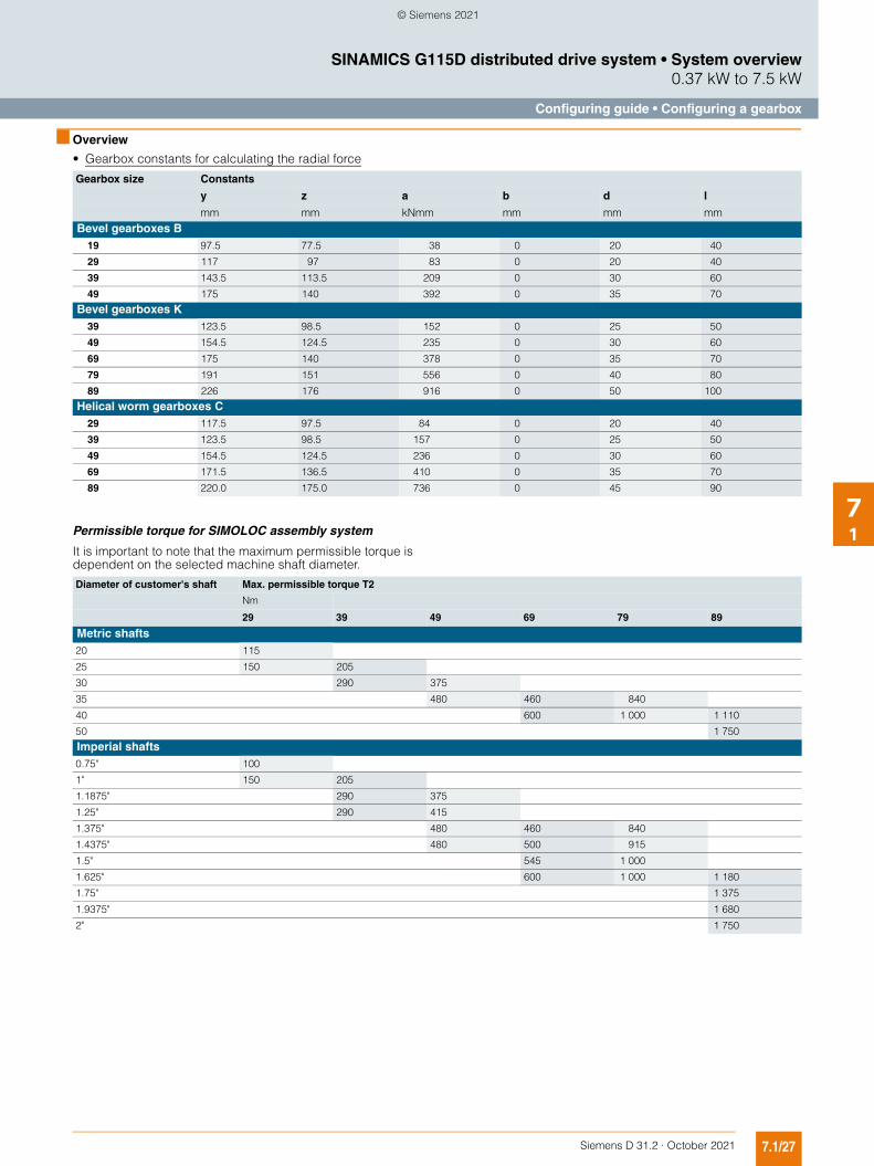
• Gearbox constants for calculating the radial force
Permissible torque for SIMOLOC assembly system
It is important to note that the maximum permissible torque is dependent on the selected machine shaft diameter.
Gearbox size Constants
y z a b d l
mm mm kNmm mm mm mmBevel gearboxes B
19 97.5 77.5 38 0 20 40
29 117 97 83 0 20 40
39 143.5 113.5 209 0 30 60
49 175 140 392 0 35 70
Bevel gearboxes K39 123.5 98.5 152 0 25 50
49 154.5 124.5 235 0 30 60
69 175 140 378 0 35 70
79 191 151 556 0 40 80
89 226 176 916 0 50 100
Helical worm gearboxes C29 117.5 97.5 84 0 20 40
39 123.5 98.5 157 0 25 50
49 154.5 124.5 236 0 30 60
69 171.5 136.5 410 0 35 70
89 220.0 175.0 736 0 45 90
Diameter of customer's shaft Max. permissible torque T2
Nm
29 39 49 69 79 89
Metric shafts20 115
25 150 205
30 290 375
35 480 460 840
40 600 1 000 1 110
50 1 750
Imperial shafts0.75" 100
1" 150 205
1.1875" 290 375
1.25" 290 415
1.375" 480 460 840
1.4375" 480 500 915
1.5" 545 1 000
1.625" 600 1 000 1 180
1.75" 1 375
1.9375" 1 680
2" 1 750
© Siemens 2021

7.1/28 Siemens D 31.2 · October 2021
SINAMICS G115D distributed drive system • System overview0.37 kW to 7.5 kW
Configuring guide • Configuring a gearbox
71
■ Overview
Additional moments of inertia
The motor moment of inertia with standard fan is specified in the motor selection lists.
Motor protection
Temperature-dependent protective devices are integrated in the motor winding and can be implemented as temperature sensors (Pt1000).
The rated response temperatures of the protective devices depend on the thermal class of the motors.
Degrees of protection
The motors are supplied in IP55 to standard IEC 60034-5. They can be installed in dusty or humid environments. The motors are suitable for operation in tropical climates. Guide value below 60 % relative air humidity for a coolant temperature of +40 °C.
Other requirements on request.
The first digit of the degree of protection indicates the degree to which an enclosure provides protection against contact and the ingress of foreign bodies.
The second digit indicates the protection that an enclosure of-fers regarding the ingress of water.
Increased corrosion protection as well as additional protective measures for the winding (protection against moisture and acid, corrosion protection in the motor) can support the selected de-gree of protection.
The degree of protection only refers to the motor. When selecting higher degrees of protection, the equipment on the gearbox side should be taken into account (seals, vents).
Cooling and ventilation
When the geared motor is mounted and the air intake is restricted, you must ensure that a minimum clearance is main-tained between the fan cover and the wall and that the cooling air is not immediately drawn in again.
Further, it must be guaranteed that the cooling air flow to the gearbox is not obstructed. As a consequence, the gearbox operating temperature can be further reduced.
Bearing system
The bearing service life of motors with horizontal mounting is 40 000 hours if there is no additional axial loading at the cou-pling output and 20 000 hours when utilized according to the maximum admissible load. This assumes that the motor is operated at 50 Hz. The nominal bearing service life is reduced for converter operation at higher frequencies.
In order to achieve the calculated lifetime in continuous opera-tion, the admissible vibration values (measured at end shield) must be determined according to evaluation zones A and B stip-ulated in ISO 10816. If higher vibration velocities occur in oper-ation, special measures must be taken.
Please contact Siemens in this regard.
First digit
Brief description Second digit
Brief description
4 The motor is pro-tected against solid objects larger than 1 mm.
4 The motor is protected against water splashed from all sides.
5 The motor is protected against dust.
5 The motor is protected against strong jets of water.
6 The machine is dust-tight.
6 The motor is protected against "heavy seas" or powerful jets of water.
7 The motor is protected against immersion.
8 The motor is protected against long periods of immersion under pres-sure.
© Siemens 2021
7.1/29Siemens D 31.2 · October 2021
SINAMICS G115D distributed drive system • System overview0.37 kW to 7.5 kW
Configuring guide • Configuring a brake
71
■ Overview
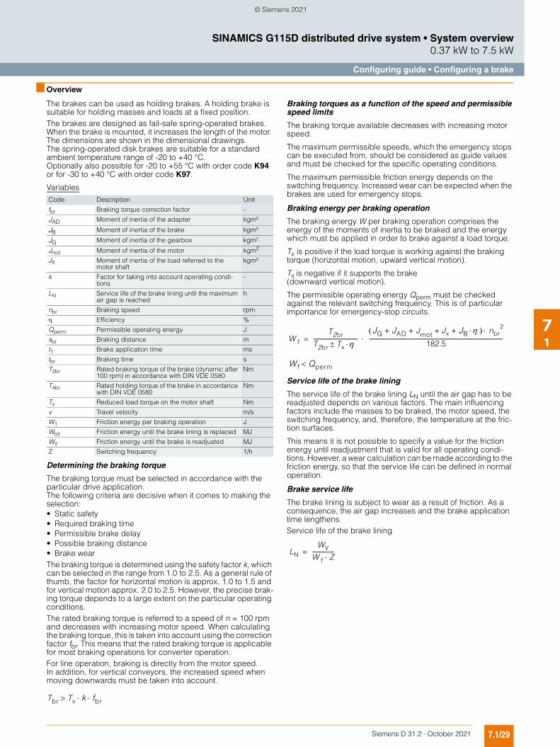
The brakes can be used as holding brakes. A holding brake is suitable for holding masses and loads at a fixed position. The brakes are designed as fail-safe spring-operated brakes. When the brake is mounted, it increases the length of the motor. The dimensions are shown in the dimensional drawings. The spring-operated disk brakes are suitable for a standard ambient temperature range of -20 to +40 °C. Optionally also possible for -20 to +55 °C with order code K94 or for -30 to +40 °C with order code K97.
Variables
Determining the braking torque
The braking torque must be selected in accordance with the particular drive application.The following criteria are decisive when it comes to making the selection:• Static safety• Required braking time• Permissible brake delay• Possible braking distance• Brake wearThe braking torque is determined using the safety factor k, which can be selected in the range from 1.0 to 2.5. As a general rule of thumb, the factor for horizontal motion is approx. 1.0 to 1.5 and for vertical motion approx. 2.0 to 2.5. However, the precise brak-ing torque depends to a large extent on the particular operating conditions.The rated braking torque is referred to a speed of n = 100 rpm and decreases with increasing motor speed. When calculating the braking torque, this is taken into account using the correction factor fbr. This means that the rated braking torque is applicable for most braking operations for converter operation.For line operation, braking is directly from the motor speed. In addition, for vertical conveyors, the increased speed when moving downwards must be taken into account.
Braking torques as a function of the speed and permissible speed limits
The braking torque available decreases with increasing motor speed.
The maximum permissible speeds, which the emergency stops can be executed from, should be considered as guide values and must be checked for the specific operating conditions.
The maximum permissible friction energy depends on the switching frequency. Increased wear can be expected when the brakes are used for emergency stops.
Braking energy per braking operation
The braking energy W per braking operation comprises the energy of the moments of inertia to be braked and the energy which must be applied in order to brake against a load torque.
Tx is positive if the load torque is working against the braking torque (horizontal motion, upward vertical motion).
Tx is negative if it supports the brake (downward vertical motion).
The permissible operating energy Qperm must be checked against the relevant switching frequency. This is of particular importance for emergency-stop circuits.
Service life of the brake lining
The service life of the brake lining LN until the air gap has to be readjusted depends on various factors. The main influencing factors include the masses to be braked, the motor speed, the switching frequency, and, therefore, the temperature at the fric-tion surfaces.
This means it is not possible to specify a value for the friction energy until readjustment that is valid for all operating condi-tions. However, a wear calculation can be made according to the friction energy, so that the service life can be defined in normal operation.
Brake service life
The brake lining is subject to wear as a result of friction. As a consequence, the air gap increases and the brake application time lengthens. Service life of the brake lining
Code Description Unit
fbr Braking torque correction factor -
JAD Moment of inertia of the adapter kgm²
JB Moment of inertia of the brake kgm²
JG Moment of inertia of the gearbox kgm²
Jmot Moment of inertia of the motor kgm2
JX Moment of inertia of the load referred to the motor shaft
kgm²
k Factor for taking into account operating condi-tions
-
LN Service life of the brake lining until the maximum air gap is reached
h
nbr Braking speed rpm
Efficiency %
Qperm Permissible operating energy J
sbr Braking distance m
t1 Brake application time ms
tbr Braking time s
T2br Rated braking torque of the brake (dynamic after 100 rpm) in accordance with DIN VDE 0580
Nm
T4br Rated holding torque of the brake in accordance with DIN VDE 0580
Nm
Tx Reduced load torque on the motor shaft Nm
v Travel velocity m/s
W1 Friction energy per braking operation J
Wtot Friction energy until the brake lining is replaced MJ
WV Friction energy until the brake is readjusted MJ
Z Switching frequency 1/h
Tbr Tx k fbr
W1
T2br
T2br Tx ---------------------------------
JG JAD J+ + mot Jx JB+ + nbr2
182.5----------------------------------------------------------------------------------------------------=
W1 Qperm
LN
WV
W1 Z----------------=
© Siemens 2021

7.1/30 Siemens D 31.2 · October 2021
SINAMICS G115D distributed drive system • System overview0.37 kW to 7.5 kW
Configuring guide • Configuring a brake
71
■ Overview
Brake control
Definition of operating times (VDI 2241)
Brake switching times
Switching times:
Brake switching time
The total time it takes the motor to come to a standstill comprises the following times:• Brake application time t1• Braking time tbr The first is the time it takes the brake to reach 90 % of its braking torque. This time may be circuit- and control-dependent.The braking time is determined as follows:
If Tx supports the braking operation, Tx is positive; otherwise it is negative.
Braking distance
Braking distance sbr is the distance traveled by the driven ma-chine during braking time tbr and application time t1.
The formula below applies to horizontal motion and upward ver-tical motion.
Relative duty cycle
The relative duty cycle DC is the ratio between the load duration and the cyclic duration. The cyclic duration is the sum of the ON times (operational periods) and the no-voltage periods.
Relative duty cycle
t1 Brake application timet2 Disconnection timet3 Slipping timet11 Response timet12 Rise time
t11 t12
t3
t1
t2Time
Time
G_D
087_
EN_0
0047
a
0.9 M
0.1 M
OFF ON
Exc
itatio
nC
hara
cter
istic
torq
ue
Code Description Unit
DC Relative duty cycle %
ts Closing time (duty cycle) s
tO Open time (off-load factor) s
tz Cycle time (duty cycle time) s
9.55 · (T2br ± Tx · )tbr =
(JG + JAD + Jmot + JB + Jx · ) · nbr
sbr vt1
1000------------- 0.5 tbr+ =
DCts
ts tO+---------------- 100=
ts tO
tz
Load
TimeG_D087_EN_00302
© Siemens 2021