catalog fi01 2013 - siemensstest1.etnetera.cz/.../chapters/cat_fi-01_ch06_2013_en.pdf · ·...
TRANSCRIPT

Siemens FI 01 · 2013
6
You can download all instructions, catalogs and certificates for Process Protection free of charge at: www.siemens.com/processprotection
6/2 Product overview
6/3 Acoustic and Motion sensing
Acoustic sensors forpump monitoring
6/5 SITRANS DA400
Acoustic sensors for material flow monitoring
6/10 SITRANS AS1006/14 SITRANS CU02
Motion sensors6/17 Milltronics MFA 4p6/23 Milltronics Millpulse 6006/26 SITRANS WM100
Process Protection
© Siemens AG 2012

Process ProtectionProduct overview
6/2 Siemens FI 01 · 2013
6
■ Overview
Application Device description Page
Acoustic sensor for pump monitoring
Acoustic diagnostics unit for flow valve leakage monitoring in oscillating displace-ment pumps or for material flow monitoring of bulk solids in pipes, conveyors or race-ways.
SITRANS DA400• 4 inputs for structure-born noise sensors
6/5
• 4 universal inputs
• 6 digital outputs
• With PROFIBUS DP or PROFIBUS PA
• Sensor degree of protection IP66/IP68
Acoustic sensors for material flow monitoring
Acoustic sensor for solids flow detection SITRANS AS100• Non-invasive
6/10
• Screw in, bolt on, weld, or bond in place
• Analog output
• High and low sensitivity range of operation
Alarm control unit for use with SITRANS AS100 acoustic sensor to provide reliable continuous protection for bulk solid flowIt processes signals from the sensor, providing relay and analog outputs for interface into a process.
SITRANS CU02• 3 digit LCD display
6/14
• 4 ... 20 mA output
• Two programmable relays
• Adjustable independent time delay for each relay
• DIN rail mounting provides easy installation
Motion sensors
Highly sensitive single set point motion sensor alarm unit, used with MSP and XPP probes
Milltronics MFA 4p• Probe/target separation up to
100 mm (4 inch)
6/17
• Minimum velocity of moving ferrous target: 1 cm/sec. (2 fpm)
Heavy-duty 2-wire motion sensor provid-ing solid state switch output to PLCs between 18 ... 135 V AC or DC
Milltronics Millpulse 600• Provide pulse output to PLC input
when monitoring speed of rotating, reciprocating or conveying equipment
6/23
Heavy-duty zero speed alarm switch Milltronics SITRANS WM100• Detects the absence or presence of
motion of rotating or reciprocating or conveying equipment
6/26
© Siemens AG 2012

Process ProtectionAcoustic and Motion sensing
6/3Siemens FI 01 · 2013
6
■ Overview
Process protection devices act as early warning systems to avoid costly process interruptions and breakdowns of equipment. Non-contacting motion sensors detect changes in motion and speed of conveying, reciprocating and rotating machinery.
Non-invasive acoustic sensors detect inaudible, high frequency acoustic emissions generated by friction and impact, caused by materials in motion. They can detect conditions of flow/no flow or high/low flow, to warn of blockages, product absence or equipment failure. They are located outside of the process, accurately detecting conditions without wear on the sensor.
Motion sensors can warn in case of equipment malfunction and shut down machinery in case of a slowdown or failure. They are rugged and perform even in harsh industrial conditions. Most of the MFA 4p motion sensing probes as well as the Millpulse 600 and the SITRANS WM100 can be mounted up to 100 mm (4 inch) from the ferrous target, reducing the chance of damage to the probe and the equipment. The probes are not affected by moisture or dust build-up.
Motion sensing on drive shaft of rotary feeder
■ Mode of operation
Acoustic Sensing
Acoustic sensors monitor high frequency emissions generated by friction and the impact of flowing material or mechanical parts. The sensors can also sense the turbulence of gases or liquids leaking through valves and flanges. When matter vibrates between 0 Hz and 200 kHz, it creates acoustic energy. Sound energy between 20 Hz and 20 kHz can be detected by humans. Acoustic sensors detect high-frequency acoustic energy between 75 kHz and 175 kHz. Acoustic energy travels quickly through dense materials (metal) and poorly through less dense materials (air). Because the acoustic sensors are mounted directly to the external wall of the chute work, other plant noises are well below 75 kHz and effectively ignored by the sensors.
The acoustic sensors contain a specialized piezocrystal and filter circuit that responds effectively to the high-frequency band between 75 kHz and 175 kHz. As the crystal is excited by the acoustic energy, it produces a continuous electrical signal in direct proportion to the level of acoustic energy received. The SITRANS AS100 sensor output of 0 to 10 V DC can be applied to a PLC or to an optional control unit for a programmable alarm relay or 4 to 20 mA signal output.
Motion sensing
Siemens Milltronics probes work on the principle of Faraday’s Laws of Electromagnetic Induction. When a ferromagnetic object enters the probe’s permanent magnetic field, it distorts the flux, causing its coil windings to generate a voltage. This voltage is proportional to the strength of the magnet and the number of wire turns in the coil (constant in the probes) and the speed at which the ferrous target passes through the flux. The generated voltage is also inversely proportional to the square of the distance between the target and the probe.
The robust motion sensors provide the contacts to shut down machinery whenever under-speed, over-speed or plant equipment failure occurs. On belt, drag and screw conveyors, or on bucket elevators, fans and pumps, the speed alarm option can warn instantly of equipment malfunction. Some probes may be linked to a programmable logic controller to monitor equipment.
© Siemens AG 2012
Process ProtectionAcoustic and Motion sensing
6/4 Siemens FI 01 · 2013
6
■ Technical specifications
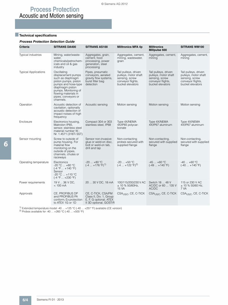
Process Protection Selection Guide
1) Extended temperature model -40 ... +125 °C (-40 ... +257 °F) available (CE version)2) Probes available for -40 ... +260 °C (-40 ... +500 °F)
Criteria SITRANS DA400 SITRANS AS100 Milltronics MFA 4p Milltronics Millpulse 600
SITRANS WM100
Typical industries Mining, water/waste-water, chemicals/petrochem-icals and oil & gas industry
Aggregates, grain, cement, food processing, power generation, steel processing
Aggregates, cement, mining, wastewater, grain
Aggregates, cement, mining
Aggregates, cement, mining
Typical Applications Oscillating displacement pumps such as diaphragm piston pumps, piston pumps and hose-type diaphragm piston pumps. Monitoring of flowing materials in pipes, conveyors or channels.
Pipes, pneumatic conveyors, aerated gravity flow systems, burst filter bag detection
Tail pulleys, driven pulleys, motor shaft sensing, screw conveyor flights, bucket elevators
Tail pulleys, driven pulleys, motor shaft sensing, screw conveyor flights, bucket elevators
Tail pulleys, driven pulleys, motor shaft sensing, screw conveyor flights, bucket elevators
Operation Acoustic detection of cavitation, optionally acoustic detection of impact noises of high frequency
Acoustic sensing Motion sensing Motion sensing Motion sensing
Enclosure Electronics housing, Makrolon IP65, sensor, stainless steel material number W.-Nr. 1.4571 (316Ti SST)
Compact 304 or 303 stainless steel, IP68
Type 4X/NEMA 4X/IP65 polycar-bonate
Type 4X/NEMA 4X/IP67 aluminum
Type 4X/NEMA 4X/IP67 aluminum
Sensor mounting Screw to outside of pump housing. For material flow monitoring on the outside of pipes, channels, chutes or raceways
Sensor non-invasive: glue or weld-on disc, bolt or weld-on tab, drill and tap
Non-contacting probes secured with supplied flange
Non-contacting, secured with supplied flange
Non-contacting, secured with supplied flange
Operating temperature Electronics-20 °C ... +60 °C (-4 °F ... +140 °F)Sensor-20 °C ... +110 °C (-4 °F ... +230 °F)
-20 ... +80 ºC (-4 ... +176 ºF)1)
-20 ... +50 ºC (-4 ... +122 ºF)2)
-45 ... +60 ºC (-49 ... +140 ºF)
-40 ... +60 ºC (-40 ... +140 ºF)
Power requirements 19 V ... 36 V DC, < 100 mA
20 ... 30 V DC, 18 mA 100/115/200/230 V AC ± 10 % 50/60Hz, 15 VA
Switch 18 ... 48 V AC/DC or 60 ... 135 V AC/DC
115 or 230 V AC± 10 % 50/60 Hz, 7 VA
Approvals CE, PROFIBUS DP and PROFIBUS PA conform, Ex protection to ATEX 1G or 1D
CE, C-TICK, CSA/FM Class II, Div. 1, Group E, F, G optional, ATEX II 3D optional, GOST-R
CSAUS/C, CE, C-TICK CSAUS/C, CE, C-TICK CSAUS/C, CE, C-TICK
© Siemens AG 2012

Process ProtectionAcoustic sensors for pump monitoring
SITRANS DA400
6/5Siemens FI 01 · 2013
6
■ Overview
The SITRANS DA400 acoustic diagnostic unit acoustically measures the structure-borne noise• In the version for pump monitoring; on oscillating
displacement pumps• In the version for material flow monitoring; on pipes, conveying
equipment or channels.
It comprises an electric diagnostic unit and up to four acoustic sensors.
■ Benefits
Benefits when pump monitoring• Increased availability of the system through:
- Advanced maintenance planning thanks to early recognition of defective components
- Reduced downtimes (no fault locating necessary)- Increased maintenance intervals- Greater pump reliability
• Prevention of expensive consequential damage• Increased safety of critical applications• Early recognition of a reduction in power• Increased productivity
Benefits when material flow monitoring• Detection of insufficient or excessive inflow of material in a
liquid or gas flow• Detection of blockages or clogging• Reduction of down times• Increased product quality• Increased availability • Guaranteed operational safety• Increased productivity
■ Application
In the version for pump monitoring, the SITRANS DA400 allows continuous, simultaneous and independent monitoring of up to four flow control valves in a pump for leaks. In addition, another four inputs are available for monitoring standard signals (e.g. diaphragm and temperature monitoring). This means that the condition of an oscillating displacement pump is monitored in every phase of its operation.
The SITRANS DA400 is used in all industries where an oscillating displacement pump is used.
The version for material flow monitoring monitors the material flow in liquids or gases that is usually as a result of impact or friction, e.g. against the pipe or channel wall.
If the acoustic diagnostic unit is used in potentially explosive areas, the sensors as well as the acoustic diagnostic unit can be installed in the Ex-zone.
If using the unit in potentially explosive areas, you have two options:• Operation of the sensors over the safety barriers or • Operation of the sensors over the SITRANS DA400 with
explosion protection
■ Function
Product features
Continuous and independent status monitoring:• Of the flow control valves, for leaks • Of the membranes, for material fatigue • Of the temperature loading of the hydraulic oil • Of flowing bulk solids in pipes, conveying equipment or
channels
Communication of the status to superordinate control systems:• Via digital outputs • Digitally, via PROFIBUS DP or PROFIBUS PA
Simple to operate and parameterize:• Locally, via digital display and keys • PROFIBUS DP and PROFIBUS PA
Mode of operation
Principle of measurement
Leaks in the flow control valves of oscillating displacement pumps are flows in which cavitation occurs. This results in sound waves that are transmitted to the valve housing, where they are recorded by the structure-borne sound sensor in the SITRANS DA400 on the outside.
The SITRANS DA400 utilizes the fact that with both an open valve and a closed intact valve, no cavitation occurs and the measured sound level thus corresponds to the operating noise of the pump. By contrast, with a closed defective valve cavitation does occur, which can be identified by a period increase in the sound level (see figures). The measured value from the SITRANS DA400 corresponds exactly to this increase in the sound level.
In the version for material flow monitoring, SITRANS DA400 continuously detects high-frequency acoustic oscillations by means of structure-born noise sensors.
© Siemens AG 2012

Process ProtectionAcoustic sensors for pump monitoring
SITRANS DA400
6/6 Siemens FI 01 · 2013
6
These oscillations are created by:• Friction and impact of bulk solids in:
- pipes, raceways or channels - chutes - conveyors
• Friction and impact of mechanical parts • Bursting of bubbles • Cavitation • Turbulence in gas and liquid flows
The following shows an example of signal levels at an oscillating displacement pump
Signal from structure-borne sound sensor with intact valve
Signal from structure-borne sound sensor with defective valve
Sensor operation
The structure-borne sound sensor works on the piezoelectric principle. The structure-borne sound is injected into the sensor via the sensor base (mounting surface) and inside it is converted into an electrical voltage by a piezo-ceramic element. This is amplified in the sensor and transmitted via the cable.
The sensor frequency range lies in the ultrasonic range (> 20 kHz). The sensor is non-directional, i.e. the angle at which the sound wave impacts on the sensor base is not important.
Mode of operation of the safety barrier
The safety barrier comprises intrinsically-safe circuits. These circuits serve to operate intrinsically-safe components such as sensors and to isolate safety from the non-hazardous area with the SITRANS DA400 diagnostic unit.
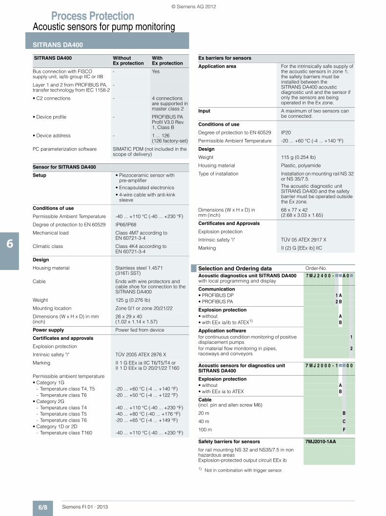
■ Technical specifications
SITRANS DA400 Without Ex protection
With Ex protection
Input
Acoustic channels 4
• Cycle time 10 ms
Only for connection to intrinsically safe sensors with:
• Max. voltage Uo - ≤ 5.5 V
• Max. current Io - ≤ 70 mA
• Max. power Po - ≤ 100 mW
• Internal capacitance Ci - ≤ 1.2 μF
• Internal inductance Li - Negligible
Universal inputs 4
• Cycle time 80 ms
• Low pass filter time 1 s
Universal analog currentinput
• Load < 105 Ω < 12 Ω
• Resolution 0.1 %
• Accuracy 0.5 %
• Fault signal > 21 mA or < 3.6 mA (at 4 ... 20 mA)
• Alarm monitoring hysteresis 0.5 %
• Static destruction limit 40 mA, 4 V -
For connection with approved intrinsically safe circuits with:
• Max. supply voltage Ui - ≤ 30 V
• Max. short-circuit current Ii - ≤ 100 mA
• Max. power Poi - ≤ 1 W
• Internal capacitance Ci - ≤ 11 nF
• Internal inductance Li - ≤ 70 μH
Universal input 24 V digitalsignal
• Input resistance > 19 kΩ
• Signal level Low < 4.5 V or open
• Signal level High > 7 V
• Hysteresis > 1 V
• Static destruction limit ± 40 V -
For connection with approved intrinsically safe circuits with:
• Max. supply voltage Ui - ≤ 30 V
• Max. short-circuit current Ii - ≤ 100 mA
• Max. power Poi - ≤ 1 W
• Internal capacitance Ci - ≤ 11 nF
• Internal inductance Li - ≤ 70 μH
© Siemens AG 2012

Process ProtectionAcoustic sensors for pump monitoring
SITRANS DA400
6/7Siemens FI 01 · 2013
6
Universal input closing contact
For connection to closing contact with the maximum values:
• Max. voltage Uo - ≤ 10 V
• Max. current Io - ≤ 1 mA
• Max. power Po - ≤ 5 mW
• Internal capacitance Ci - ≤ 11 nF
• Internal inductance Li - ≤ 70 μH8.2 V source for NAMUR signal (DIN EN 60947-5-6)
• Open circuit voltage 8.2 V ± 0.3 V, short-circuit proof
-
• Input resistance < 950 Ω -
• Static destruction limit for incorrect wiring
+20 V/-10 V -
OutputDigital outputs 6 6 (applicable for
NAMUR switch hardener)
• Semiconductor relay Individually isolated, short circuit-proof
-
• Switching voltage 24 V AC/36 V DC, any polarity
-
• Destruction limit 35 V AC, 50 V DC
-
• Max. switching current 100 mA -
• Signal status Low (no response)
- ≤ 1.2 mA (source to DIN 19234)
• Signal status High (response)
- ≥ 2.1 mA (source to DIN 19234)
For connection with an intrinsically safe switching amplifier to DIN 19234 with:
• Max. supply voltage Ui - ≤ 15.5 V
• Max. short-circuit current Ii - ≤ 25 mA
• Max. power Poi - ≤ 64 mW
• Internal capacitance Ci - ≤ 5.2 nF
• Internal inductance Li - Negligible
Conditions of use
Installation conditions Vertical wall mounting, cables fed in from below
Climatic class Class 4K4 according to EN 60721-3-4
Mounting location - Zone 1 or zone 2
Permissible ambient temperature -20 ... +60 °C (-4 ... +140 °F)
-
• Temperature class T5 – T1 -20 ... +60 °C(-4 ... +140 °F)
• Temperature class T6 -20 ... +50 °C (-4 ... +122 °F)
Mechanical load Class 4M3 according to EN 60721-3-4
Degree of protection to EN 60529 IP65
SITRANS DA400 Without Ex protection
With Ex protection
Electromagnetic Compatibility
• Emitted interference and interference immunity
To EN 61326 and NAMUR NE 21
Usage limits for water
• Delivery side ≥ 10 bar a
• Number of strokes Min. 4 min-1, max. 10 ... 500 min-1
Design
Weight (without options) Approx. 2.5 kg
Dimensions (W x H x D) in mm (inch)
172 x 320 x 80 (6.8 x 12.6 x 3.2)
Enclosure material Macrolon (polycarbonate +20 % glass fiber)
Makrolon (Polycarbonate +20 % glass fibers), surface attenuated with CrNi layer and painted
Electrical connection via screw terminals
• Rigid 2.5 mm (0.984 inch)• Flexible 1.5 mm (0.59 inch)• Flexible with connector sleeves
1.5 mm (0.59 inch)
Cable inlet via plastic cable joints • 2 x Pg 13.5• 5 x Pg 11
Power supply
Rated voltage 24 V DC 16 V DC
Operating range 19 ... 36 V DC 15 ... 17 V DC
Current consumption < 100 mA < 40 mA
For connection with approved intrin-sically safe circuits with:
• Max. supply voltage Ui - ≤ 17.4 V
• Max. short-circuit current Ii - ≤ 191 mA
• Max. power Poi - ≤ 1.35 W
• Internal capacitance Ci - ≤ 33 nF
• Internal inductance Li - ≤ 28 μH
Certificates and approvals
Explosion protection to EN 50014, EN 50020 and EN 50021
Intrinsic safety "i" - TÜV (German Technical Inspectorate) 06 ATEX 2952
Marking - II 2(1) G EEx is [ia] IIC T6
Communication
PROFIBUS DP RS 485, switch-able terminating resistor
Protocol Cyclic with Master C1 and acyclic with Master C2
Power supply - Bus-supplied
Bus voltage - 9 ... 24 V
Current consumption - 10.5 mA ± 10 %
SITRANS DA400 Without Ex protection
With Ex protection
© Siemens AG 2012
Process ProtectionAcoustic sensors for pump monitoring
SITRANS DA400
6/8 Siemens FI 01 · 2013
6
Bus connection with FISCO supply unit, ia/ib group IIC or IIB
- Yes
Layer 1 and 2 from PROFIBUS PA, transfer technology from IEC 1158-2
-
• C2 connections - 4 connections are supported in master class 2
• Device profile - PROFIBUS PA Profil V3.0 Rev. 1, Class B
• Device address - 1 ... 126(126 factory-set)
PC parameterization software SIMATIC PDM (not included in the scope of delivery)
Sensor for SITRANS DA400
Setup • Piezoceramic sensor with pre-amplifier
• Encapsulated electronics • 4-wire cable with anti-kink
sleeve
Conditions of use
Permissible Ambient Temperature -40 ... +110 °C (-40 ... +230 °F)
Degree of protection to EN 60529 IP66/IP68
Mechanical load Class 4M7 according to EN 60721-3-4
Climatic class Class 4K4 according to EN 60721-3-4
Design
Housing material Stainless steel 1.4571(316Ti SST)
Cable Ends with wire protectors and cable shoe for connection to the SITRANS DA400
Weight 125 g (0.276 lb)
Mounting location Zone 0/1 or zone 20/21/22
Dimensions (W x H x D) in mm (inch)
26 x 29 x 40 (1.02 x 1.14 x 1.57)
Power supply Power fed from device
Certificates and approvals
Explosion protection
Intrinsic safety "i" TÜV 2005 ATEX 2876 X
Marking II 1 G EEx ia IIC T6/T5/T4 orII 1 D EEx ia D 20/21/22 T160
Permissible ambient temperature• Category 1G
- Temperature class T4, T5 -20 ... +60 °C (-4 ... +140 °F)- Temperature class T6 -20 ... +50 °C (-4 ... +122 °F)
• Category 2G - Temperature class T4 -40 ... +110 °C (-40 ... +230 °F)- Temperature class T5 -40 ... +80 °C (-40 ... +176 °F)- Temperature class T6 -20 ... +65 °C (-4 ... +149 °F)
• Category 1D or 2D - Temperature class T160 -40 ... +110 °C (-40 ... +230 °F)
SITRANS DA400 Without Ex protection
With Ex protection
Ex barriers for sensors
Application area For the intrinsically safe supply of the acoustic sensors in zone 1; the safety barriers must be installed between the SITRANS DA400 acoustic diagnostic unit and the sensor if only the sensors are being operated in the Ex zone.
Input A maximum of two sensors can be connected.
Conditions of use
Degree of protection to EN 60529 IP20
Permissible Ambient Temperature -20 ... +60 °C (-4 ... +140 °F)
Design
Weight 115 g (0.254 lb)
Housing material Plastic, polyamide
Type of installation Installation on mounting rail NS 32 or NS 35/7.5.The acoustic diagnostic unit SITRANS DA400 and the safety barrier must be operated outside the Ex zone.
Dimensions (W x H x D) in mm (inch)
68 x 77 x 42 (2.68 x 3.03 x 1.65)
Certificates and Approvals
Explosion protection
Intrinsic safety "i" TÜV 05 ATEX 2917 X
Marking II (2) G [EEx ib] IIC
Selection and Ordering data Order-No.
Acoustic diagnostics unit SITRANS DA400 with local programming and display
7 M J 2 4 0 0 - 77A 0 7
Communication• PROFIBUS DP 1 A• PROFIBUS PA 2 B
Explosion protection• without A• with EEx ia/ib to ATEX1)
1) Not in combination with trigger sensor.
B
Application softwarefor continuous condition monitoring of positive displacement pumps
1
for material flow monitoring in pipes, raceways and conveyors
2
Acoustic sensors for diagnostics unit SITRANS DA400
7 M J 2 0 0 0 - 1 77 0 0
Explosion protection• without A• with EEx ia to ATEX B
Cable(incl. pin and allen screw M6)
20 m B
40 m C
100 m F
Safety barriers for sensors 7MJ2010-1AA
for rail mounting NS 32 and NS35/7.5 in non hazardous areasExplosion-protected output circuit EEx ib
© Siemens AG 2012

Process ProtectionAcoustic sensors for pump monitoring
SITRANS DA400
6/9Siemens FI 01 · 2013
6
■ Dimensional drawings
Sensor for SITRANS DA400, dimensions in mm (inch)
SITRANS DA400, dimensions in mm (inch)
Safety barrier for SITRANS DA400, dimensions in mm (inch)
■ Schematics
Safety barrier for SITRANS DA400, terminal assignment
SITRANS DA400, terminal assignment
28.5 (1.12)
6.5
(0.2
6)
6 (0.24)
26 (1
.02)
7 (0.2
8)15
(0.5
9)
9 (0.35) Ø3 (0.12)Ø40
(1.57)
11 (0.43) 10 (0.39)
Foot element
SENSOR
70 (2.7)
68 (2
.7)
Out1, Out2SITRANS DA400
In1, In2
12 (0
.5)
49 (1
.9)
47 (1
.8)
42 (1
.6)
77 (3.0)
Ground terminal
Not intrinsically safe towards
SITRANS DA400
Intrinsically safe towards
sensor
In1
22213231
22213231
In2
41425152
41425152
Out1
Out2
Power supply(Any polarity with PROFIBUS PA)
L+/L-
SensorSensDigital outputDO
In
gr
Input
greenyellowyl
br
I+
brown
Analog current input +blackbl
A
Ground
Signal A (green) with PROFIBUS DP, any with PROFIBUS PA
Digital inputDI
Signal B (red) with PROFIBUS DP, any with PROFIBUS PA
B
Supply
© Siemens AG 2012
Process ProtectionAcoustic sensors for material flow monitoring
SITRANS AS100
6/10 Siemens FI 01 · 2013
6
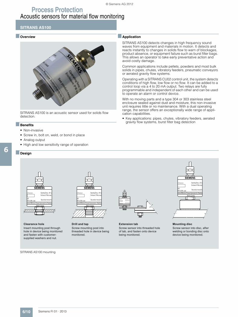
■ Overview
SITRANS AS100 is an acoustic sensor used for solids flow detection.
■ Benefits
• Non-invasive • Screw in, bolt on, weld, or bond in place • Analog output• High and low sensitivity range of operation
■ Application
SITRANS AS100 detects changes in high frequency sound waves from equipment and materials in motion. It detects and reacts instantly to changes in solids flow to warn of blockages, product absence, or equipment failure such as burst filter bags. This allows an operator to take early preventative action and avoid costly damage.
Common applications include pellets, powders and most bulk solids in pipes, chutes, vibratory feeders, pneumatic conveyors or aerated gravity flow systems.
Operating with a SITRANS CU02 control unit, the system detects conditions of high flow, low flow or no flow. It can be added to a control loop via a 4 to 20 mA output. Two relays are fully programmable and independent of each other and can be used to operate an alarm or control device.
With no moving parts and a type 304 or 303 stainless steel enclosure sealed against dust and moisture, this non-invasive unit requires little or no maintenance. With a dual operating range, the sensor offers an exceptionally wide range of appli-cation capabilities.• Key applications: pipes, chutes, vibratory feeders, aerated
gravity flow systems, burst filter bag detection
■ Design
SITRANS AS100 mounting
Screw sensor into disc, after welding or bonding disc onto device being monitored.
Mounting discScrew sensor into threaded hole of tab, and fasten onto device being monitored.
Extension tabScrew mounting post into threaded hole in device being monitored.
Drill and tapInsert mounting post through hole in device being monitored and fasten with customer-supplied washers and nut.
Clearance hole
© Siemens AG 2012
Process ProtectionAcoustic sensors for material flow monitoring
SITRANS AS100
6/11Siemens FI 01 · 2013
6
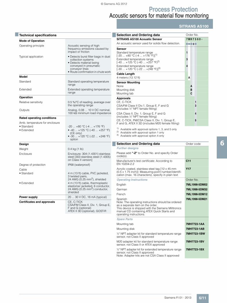
■ Technical specifications
Mode of Operation
Operating principle Acoustic sensing of high frequency emissions caused by impact or friction
Typical application • Detects burst filter bags in dust collection systems
• Detects material being conveyed in pneumatic conveyor lines
• Route confirmation in chute work
Model
Standard Standard operating temperature range
Extended Extended operating temperature range
Operation
Relative sensitivity 0.5 %/ºC of reading, average over the operating range
Outputs Analog, 0.08 ... 10 V DC nominal, 100 kΩ minimum load impedance
Rated operating conditions
Amb. temperature for enclosure• Standard -20 ... +80 °C (-4 ... +176 °F)• Extended • -40 ... +125 °C (-40 ... +257 °F)
(CE only) • -30 ... +120 °C (-22 ... +248 °F)
option
Design
Weight 0.4 kg (1 lb)
Enclosure Enclosure: 304 (1.4301) stainless steel [303 stainless steel (1.4305) on Class II version]
Degree of protection IP68 (waterproof)
Cable• Standard 4 m (13 ft) cable, PVC jacketed,
3 twisted pairs, 24 AWG (0.25 mm2), shielded
• Extended 4 m (13 ft) cable, thermoplastic elastomer jacketed, 6 conductor, 24 AWG (0.25 mm2) conductor, shielded
Power supply 20 ... 30 V DC, 18 mA (typical)
Certificates and approvals CE, C-TICKCSA/FM Class II, Div. 1, Group E, F and G (optional)ATEX II 3D (optional), GOST-R
■ Selection and Ordering data Order No.
SITRANS AS100 Acoustic SensorAn acoustic sensor used for solids flow detection.
7 M H 7 5 6 0 -
777 0 7
SensorStandard temperature range [-20 ... +80 °C (-4 ... +176 °F)]1)
1) Available with approval options 1, 3, and 5 only
1
Extended temperature range[-40 ... +125 °C (-40 ... +257 °F)2)
2) Available with approval option 1 only
3
Extended temperature range [-30 ... +120 °C (-22 ... +248 °F)]3)
3) Available with approval option 4 only
4
Cable Length4 meters (13.12 ft) A
Sensor MountingNone AMounting disk BMounting tab C
ApprovalsCE, C-TICK 1CSA/FM Class II Div.1, Group E, F and G (includes ½" NPT female fitting)
3
CSA Class II, Div. 1, Group E, F and G (includes ½" NPT female fitting)
4
CE, C-TICK, FM/CSA Class II, Div. 1, Group E, F and G, ATEX II 3D (includes M20 female fitting)
5
Selection and Ordering data Order code
Further designs
Please add "-Z" to Order No. and specify Order code(s).
Manufacturer’s test certificate: According to EN 10204-2.2
C11
Acrylic coated, stainless steel tag [12 x 45 mm (0.5 x 1.75 inch)]: Measuring-point number/identifi-cation (max. 16 characters), specify in plain text
Y17
Operating Instructions Order No.
English 7ML1998-5DM02
German 7ML1998-5DM32
French 7ML1998-5DM12
SpanishNote: The operating instructions should be ordered as a separate item on the order.This device is shipped with the Siemens Milltronics manual CD containing ATEX Quick Starts and operating instructions.
7ML1998-5DM21
Spare Parts
Mounting tab 7MH7723-1AA
Mounting disk 7MH7723-1AB
½" NPT adapter kit for standard temperature range sensor, not Class II approved
7MH7723-1BW
M20 adapter kit for standard temperature range sensor, not Class II or ATEX approved
7MH7723-1BV
½" NPT adapter kit for extended temperature range sensor, not Class II approvedNote: Adapter kits are not CSA Class II approved
7MH7723-1BX
© Siemens AG 2012

Process ProtectionAcoustic sensors for material flow monitoring
SITRANS AS100
6/12 Siemens FI 01 · 2013
6
■ Dimensional drawings
SITRANS AS100, dimensions in mm (inch)
SITRANS AS100 accessories, dimensions in mm (inch)
SITRANS AS100 (class II rated ST and ET versions)
½" NPT female conduit fitting (M20 fitting for ATEX version)
Mounting post, 17A/F nut and M10 thread
6 x 24 AWG cable
Mounting post, 17A/F nut and M10 thread
6 x 24 AWG cable
SITRANS AS100 (ST and ET versions)
82 (3
.2)
67 (2
.7)
36 (1
.4)
8 (0
.3) 44 (1.8)
17
(0.7
)
36 (1
.4)
8 (0
.3) 44 (1.8)
32
(1.3
)
Mounting Disc - Bonded or Welded(304 stainless steel)
SITRANS AS100Mounting hole M10 thread
Bolt hole, 14 (0.55)
Extension Tab - Bolt on (304 stainless steel)
Accessories
SITRANS AS100Mounting hole M10 thread
10 (0
.4)
30 (1
.2)
85 (3.3)
Ø 3
0 (1
.2)
15 (0
.6)
15 (0.6)
15 (0.6)
© Siemens AG 2012

Process ProtectionAcoustic sensors for material flow monitoring
SITRANS AS100
6/13Siemens FI 01 · 2013
6
■ Schematics
SITRANS AS100 connections
* Sensor range selectionHigh sensitivity range = red and green to Vsup+Low sensitivity range = red to Vsup+, green to Vsup-
* Sensor range selectionHigh sensitivity range = red and orange to Vsup+Low sensitivity range = red to Vsup+, orange to Vsup-
Max. distance between sensor and supply (24 V or Control Unit).
The longer the cable, the more susceptible it is to noise and earth loops. It is therefore recommended to use cable with heavy gauge conductors and good RF/electrical shielding (copper braid rather than drain and foil). A proper junction box close to the sensor is an ideal location not only to extend the cable but also to configure the wiring for high or low sensitivity range operation.The following table provides a guideline for suitable wire gauges where distances are considerable.
Interconnection
Or*
Brw
Blk
Blk
Blk
Yel
Wht
Grn
Vsens: analog output0.08 ... 10 V DC nominal
Vsup: 20 ... 30 V DC supply input
Shield, tied to Sensor casing
Red
Standard temperature range
Extended temperature range
shield, tied to Sensor casing
Wire size Distance
7 x 0.207 x 0.2510 x 0.25
0.250.350.5
meters feet
Or*
Vsens: analog output0.08 ... 10 V DC nominal
Vsup: 20 ... 30 V DC supply inputBlk
Grn
Red
Org
+-
+-
+-
+-
AWG242220
500800
1 200
1 6002 6003 900
mm mm2
© Siemens AG 2012

Process ProtectionAcoustic sensors for material flow monitoring
SITRANS CU02
6/14 Siemens FI 01 · 2013
6
■ Overview
SITRANS CU02 is an alarm control unit, for use with SITRANS AS100 acoustic sensor, that provides reliable continuous protection for bulk solids flow.
■ Benefits
• 4 to 20 mA output • Two programmable relays • Adjustable independent time delay for each relay • Adjustable start-up time delay • DIN rail mounting provides easy installation • Built-in password protection to parameters
■ Application
SITRANS CU02 receives a 0 to 10 V DC input signal from the SITRANS AS100 sensor, providing relay and analog outputs for interface into a process.• Key applications: with SITRANS AS100 for bulk solids flow
■ Function
The system can be readily configured for set points indicating such conditions as high flow, low flow or no flow. Alternatively, it can be added to a control loop via a 4 to 20 mA isolated output for trend monitoring proportional to the signal from the sensor.
Two relays are fully programmable and independent of each other and can be used to operate an alarm or control device. Alarming may be provided above or below a setpoint or within a band. Readings are also displayed locally by the SITRANS CU02 on its LCD.
The SITRANS CU02 may be mounted up to 500 m (1 500 ft) from the sensor.
■ Technical specifications
Mode of operation
Measuring principle Controller for acoustic sensing (SITRANS AS100)
Typical application Connects to SITRANS AS100 to detect burst filter bag
Input 0 … 10 V DC, from sensor
Output
Output signal 4 … 20 mA isolated output, 2 Form C relays - latching or non-latching – 5 A at 250 V AC non-inductive
Sensor excitation 26 V DC
Max. load 750 Ω
Rated operating conditions
Installation conditions • Location Indoor
Ambient conditions • Ambient temperature for enclosure -20 … +50 °C (-4 … +122 °F)• Relative humidity 80 % for temperatures
up to 50 °C (122 °F)• Degree of protection IP20• Installation category II• Pollution degree 2
Design
Weight 550 g (18 oz)
Dimensions (W x H x D) 55 x 75 x 110 mm (2.2 x 3 x 4.4 inch)
Material enclosure Polycarbonate
Mounting DIN Rail (DIN 46277 or DIN EN 50022), or wall mount, up to 500 m (1 500 ft) from sensor
Cable 2 twisted pair, 24 AWG (22 mm²), shielded. Mount up to 500 m (1 500 ft) from sensor
Display Liquid crystal, three digits, 9 mm (0.35 inch), high and multi-segment graphic symbols for operation status
Power supply
Supply voltage 100, 115, 200, 230 V AC ± 15 %, 50/60 Hz, factory set
Power consumption Max. 10 VA
Approvals CSAUS/C, CE, C-TICK, GOST-R
© Siemens AG 2012

Process ProtectionAcoustic sensors for material flow monitoring
SITRANS CU02
6/15Siemens FI 01 · 2013
6
■ Dimensional drawings
SITRANS CU02, dimensions in mm (inch)
Selection and Ordering data Order No.
SITRANS CU02 Control UnitAlarm control unit for use with SITRANS AS100 acoustic sensor to provide reliable continuous pro-tection for bulk solid flow
7 M H 7 5 6 2 -
777
Power Supply100 V AC 1115 V AC 2200 V AC 3230 V AC 4
EnclosureStandard DIN Rail A
ApprovalsCSAUS/C, CE, C-TICK A
Selection and Ordering data Order code
Further designs
Please add "-Z" to Order No. and specify Order code(s).
Manufacturer’s test certificate: According to EN 10204-2.2
C11
Acrylic coated, stainless steel tag [38 x 51 mm (1.5 x 2 inch)]: Measuring-point number/identification(max. 16 characters), specify in plain text
Y18
Operating Instructions Order No.
English 7ML1998-5DN01
French 7ML1998-5DN11
GermanNote: The operating instructions should be ordered as a separate item on the order.This device is shipped with the Siemens Milltronics manual CD containing the complete operating instructions library.
7ML1998-5DN31
Drill and tap for Ø4 (#8) screw,
(2 places)
4.5 x 5.75 (0.18 x 0.2)Mounting slot (2 places)
Wall/panel mounting
61 (2
.4)
38 (1.5)
61 (2
.4)
38 (1.5)
55 (2.2)
75 (3
)
110 (4.4)
© Siemens AG 2012

Process ProtectionAcoustic sensors for material flow monitoring
SITRANS CU02
6/16 Siemens FI 01 · 2013
6
■ Schematics
SITRANS CU02 connections
Standard temperature version
Extended temperature version
* Sensor range selectionHigh sensitivity range = green to 'Vsup'Low sensitivity range = green to 'com'
All field wiring must have insulation suitable for at least 250 V. Relay contact terminals are for use with equipment having no accessible live parts and wiring having insulation suitable for at least 250 V.The maximum allowable working voltage between adjacent relay contacts shall be 250 V. If sensor case is grounded, do not connect shield of cable to SITRANS CU02 ground terminal.
Interconnection
Installation shall only be performed by qualified personnel and in accordance with local governing regulations.This product is susceptible to electrostatic shock. Follow proper grounding procedures.
Mounting
or*
or* brw
blkblk blk
yel
wht
grnred
blk
grn
red
orange
* Sensor range selectionHigh sensitivity range = orange to 'Vsup'Low sensitivity range = orange to 'com'
Jumper allows automatic reset or use remote push button to unlatch
shield
shield
100, 115, 200, 230 V AC, 10 VA Factory set
0 ... 10 V DCsignal I/P
Excitation voltage
Analog output
RL1 RL2 L1 L2N
15 169 10 11 12 13 14
7 81
4-20
2- +
3 4 5
mA out Vsup Vsenscom
6
*
*
latch
© Siemens AG 2012

Process ProtectionMotion sensors
Milltronics MFA 4p
6/17Siemens FI 01 · 2013
6
■ Overview
MFA 4p motion failure alarm controller is a highly sensitive single setpoint motion sensor system, used with Milltronics MSP and XPP probes.
■ Benefits
• Up to 100 mm (4 inch) gap between target and probe • Switch selectable overspeed or underspeed detection • Setpoint adjustment 0.15 to 3 000 PPM (pulses/minute) • Adjustable start-up time delay • Visual indication of probe operation and relay status • General purpose, suitable for majority of industrial applica-
tions; rugged probe designs provide unmatched reliability
■ Application
The MFA 4p detects changes in the motion and speed of rotating, reciprocating or conveying equipment. It warns of equipment malfunction and signals through contacts to shut down machinery in case of a slowdown or failure. Its reliability makes it a cost-effective way to protect valuable process equipment.
The single setpoint system suits most industrial applications. This versatile unit can be used on tail pulley shafts, driven pulleys, motor shaft sensing, belt or drag conveyors, screw conveyor flights, bucket elevators, fans and pumps.
A special feature is the adjustable 0 to 60 second time delay, allowing the monitored device to accelerate to normal running speed before monitoring begins. A wide range of probes are available to suit specific needs, including high temperatures, corrosive, and Class I, II and III installations. The CE approval allows the MFA 4p to consistently meet the needs of the mining aggregate, cement and other primary and secondary industries.• Key Applications: tail pulleys, motor shaft sensing, screw
conveyor flights, bucket elevators
■ Design
Mounting
MSP-1, MSP-12, MSP-3, MSP-9, XPP-5 mounting, dimensions in mm (inch)
95 (3.75) dia.Probe clearance hole 6 (0.25) dia. Hole for 1/4-20 bolt
or drill and tap on 114 (4.5) BCD, 4 places
6 (0.25) dia. Hole for 1/4-20 bolt or drill and tap on 114 (4.5) BCD, 4 places
Panel
Mounting for Milltronics MSP-9
Mounting flange supplied with probe.Note:For MSP-1 29 mm (1.125 inch) clearance hole required.Note:
Mounting for Milltronics MSP-12, MSP-3, XPP-5
Probe flange
95 (3.75) dia.Probe clearance hole
6 (0.25) dia. Hole for 1/4-20 bolt or drill and tap on 114 (4.5) BCD, 4 places
6 (0.25) dia. Hole for 1/4-20 bolt or drill and tap on 114 (4.5) BCD, 4 places
25 (1) 2 inch NPSL
133
(5.2
5)
102 (4)
102
(4)
© Siemens AG 2012

Process ProtectionMotion sensors
Milltronics MFA 4p
6/18 Siemens FI 01 · 2013
6
Probes
MFA 4p motion probes
■ Technical specifications
Milltronics RMA (Remote Mounted Amplifier)
Heavy-duty, high temperature aluminum probe designed to withstand operating temperatures to 260 °C (500 °F)
High temperature Milltronics MSP-3
Milltronics XPP-5
Miniature Milltronics MSP-1
Stainless high temperature Milltronics MSP-9
Temperature rating: -40 ... +60 °C (-40 ... +140 °F)
Convenient mounting flange and locknut for fast installation and setup
Long lasting phenolic body with internal amplifier
Heavy-duty general purpose motion probeStandard Milltronics MSP-12 •
•
Cast aluminum probe with convenient mounting flange and locknut
•
Heavy-duty, high temperature 304 stainless steel probe
• Available for internal mounting within Probe, or in enclosure for remote mounting
•
Enclosures available in cast aluminum (½" NPT entry), painted steel (Type/NEMA 4 rating) or stainless steel (Type/NEMA 4X, IP65 rating)
•
Operating temp. from -40 ... +60 °C (-40 ... +140 °F)•Enclosure rating: Type/NEMA 4X, 6, IP67•
Special construction allows operation of probe in environment up to 260 °C (500 °F)
•
1.5 m (5 ft) special high temperature PTFE cable provided. Up to 30 m (100 ft) may be used.
•
Amplifier remote mounted in enclosure 140 x 140 x 100 mm (5.5 x 5.5 x 4 inch), available in cast aluminum (½" NPT conduit entry), painted steel (Type/NEMA 4, IP65 rating), or stainless steel (Type/NEMA 4X, IP65 rating)
•
1.5 m (5 ft) of high temperature PTFE cable provided. Up to 30 m (100 ft) may be used.
•
Amplifier remote mounted in enclosure 140 x 140 x 100 mm (5.5 x 5.5 x 4 inch), available in cast aluminum (½" NPT conduit entry), painted steel (Type/NEMA 4, IP65 rating), or stainless steel (Type/NEMA 4X, IP65 rating)
•
Amplifier temperature rating -40 ... +60 °C (-40 ... +140 °F)
•
Enclosure rating: Type/NEMA 4X, 6, IP67•
•
•
•Enclosure rating: Type/NEMA 4X, 6, IP67•
CSA hazardous approval (Class I, Div. 1, Groups A, B, C & D; Class II, Div. 1, Groups E, F & G; Class III)
•
Phenolic / aluminum body that is fully potted•Convenient mounting flange and locknut•
Enclosure rating: Type/NEMA 4X, 6, IP67•
3/4 inch NPT male hub connection•Operating temp. from -40 ... +60 °C (-40 ... +140 °F)•Enclosure rating: Type/NEMA 4X, 6, IP67•
Miniature probe for installations with limited mounting space
•
CPVC probe body complete with locknuts•
Enclosure rating: Type/NEMA 4X, 6, IP67•
1.8 m (6 ft) cable provided. Up to 30 m (100 ft) may be used.
•
Amplifier remote mounted in enclosure 140 x 140 x 100 mm (5.5 x 5.5 x 4 inch), available in cast aluminum (½" NPT conduit entry), painted steel (Type/NEMA 4, IP65 rating), or stainless steel (Type/NEMA 4X, IP65 rating)
•
Due to smaller size, probe sensitivity is reduced, gap max. 13 mm (0.5 inch)
•
Amplifier temperature rating -40 ... +60 °C (-40 ... +140 °F)
•
Mode of operation
Measuring principle Motion monitor and alarm
Typical application Monitoring loss of motion in tail pulley, screw flights, bucket elevators
Features • Switch selectable overspeed or underspeed detection
• Setpoint adjustment:0.15 ... 3 000 PPM
• Adjustable start-up time delay: 0 ... 60 seconds
• Visual indication of probe operation and relay status
Output 2 relays working in unison, each providing 1 SPDT Form C relay contact, rated 8 A at 250 V AC resistive
Performance
Repeatability ± 1 %
Dead band ± 0.25 %
Dynamic Range 0 ... 7 200 PPM
Ambient Temperature Range -20 ... +50 °C (-5 ... +122 °F)
Design
Enclosure rating Type 4X/NEMA 4X/IP65 (standard and optional stainless steel)Type 4/NEMA 4/IP65 (optiona mild steel)
Enclosure dimensions 160 x 240 x 82 mm (6.3 x 9.5 x 3.2 inch)optional: mild steel or 304 (1.4301) stainless steel203 x 254 x 102 mm (8 x 10 x 4 inch)
Enclosure material Polycarbonate optional: mild steel or stainless steel
Power Supply 100/115/200/230 V AC switch selectable, 50/60 Hz, 15 VA ± 10 % of rated voltage
Certificates and approvals CE, C-TICK, CSAUS/C, FM
© Siemens AG 2012
Process ProtectionMotion sensors
Milltronics MFA 4p
6/19Siemens FI 01 · 2013
6
.
Selection and Ordering data Order No.
MFA 4P Motion Failure Alarm ControllerA highly sensitive single setpoint motion sensor system, used with MSP and XPP probes.
7 M H 7 1 4 4 -
7777
EnclosureNEMA 4X, polycarbonate enclosure 1NEMA 4, painted mild steel enclosure 2NEMA 4X, 304 (1.4301) stainless steel enclosure 3
Input Voltage100/115/200/230 V AC, 50/60 Hz, switch selectable A
Speed detection versionStandard, underspeed (U/S) or overspeed (O/S), switch selectable
A
Slow speed (S/S), U/S or O/S detection, switch selectable (limit of 15 ppm)
B
ApprovalsCE, C-TICK, CSAUS/C, FM 2
Selection and Ordering data Order code
Further designs
Please add "-Z" to Order No. and specify Order code(s).
Manufacturer’s test certificate: According to EN 10204-2.2
C11
Acrylic coated, stainless steel tag [69 x 50 mm (2.7 x 1.97 inch)]: Measuring-point number/identifi-cation (max. 27 characters), specify in plain text
Y15
Painted mild steel, heated enclosure with viewing window for use down to -50 °C (-58 ºF) (finished unit is mounted inside enclosure) 483 x 584 x 203 mm (19 x 23 x 8 inch)
A35
Stainless steel, sun/weather shield (finished unit is field mounted inside enclousre) [357 x 305 x 203 mm (14 x 12 x 8 inch)]
S50
Operating Instructions Order No.
English 7ML1998-5FM01
French 7ML1998-5FM11
Spanish 7ML1998-5FM21
GermanNote: The operating instructions should be ordered as a separate item on the order.
7ML1998-5FM31
Spare Parts
Relay 7MH7723-1DW
Transformer 7MH7723-1DX
Circuit Card, standard 7MH7723-1DU
Circuit Card, Slow speed 7MH7723-1DV
Lid with overlay for MFA 4p 7MH7723-1GY
Selection and Ordering data Order No.
Milltronics RMA Remote Mounted AmplifierRemote mounted amplifier for Milltronics MSP-1, MSP-3 and MSP-9 motion sensing probes.
7MH7145-
0 7
EnclosureAluminum enclosure, IP65, Type/NEMA 4X, ½" NPT entry
A
Painted steel, Type/NEMA 4, IP65 rating C304 (1.4301) stainless steel enclosure, Type/NEMA 4X, IP65 rating
D
Selection and Ordering data Order code
Further designs
Please add "-Z" to Order No. and specify Order code(s).
Manufacturer’s test certificate: According to EN 10204-2.20
C11
Acrylic coated, stainless steel tag [38 x 51 mm (1.5 x 2 inch)]: Measuring-point number/identifica-tion (max. 16 characters), specify in plain text
Y18
Operating Instructions Order No.
English 7ML1998-5FM01
French 7ML1998-5FM11
Spanish 7ML1998-5FM21
GermanNote: The operating instructions should be ordered as a separate item on the order.This device is shipped with the Siemens Milltronics manual CD containing the complete operating instructions library.
7ML1998-5FM31
Spare Parts
Card, RMA 7MH7723-1DT
© Siemens AG 2012

Process ProtectionMotion sensors
Milltronics MFA 4p
6/20 Siemens FI 01 · 2013
6
Selection and Ordering data Order No.
Milltronics Motion Sensing ProbesA series of motion sensing probes used with the MFA 4p.Milltronics MSP-1: miniature motion sensing probeMilltronics MSP-3: heavy-duty, high temperature aluminumMilltronics MSP-9: heavy-duty, high temperature stainless steelMilltronics MSP-12: heavy-duty, general purposeMilltronics XPP-5: hazardous ratedNote: Milltronics MSP-1, MSP-3 and MSP-9 probes require the use of Milltronics RMA (amplifier)
7 M H 7 1 4 6 -
777
Cable LengthStandard length (as described in Model options)1)
1) No Y01 needed in order code for standard length
0Add order code Y01 and plain text:"Total cable length ... m"Extended cable length 2 ... 30 m (6.6 ... 98.4 ft)2)
2) Only available with model options A, B, D, G, H, and J
1Extended cable length 31 ... 50 m (101.7 ... 164 ft)3)
3) Available with Model option G only
2
Extended cable length 51 ... 100 m(167.3 ... 328.1 ft)
3
Model [standard cable length/type]MSP-1 [1.8 m (6 ft)]4)
4) MSP-1, MSP-3 and MSP-9 probes required the use of RMA (amplifier)
AMSP-3, ½" NPT cable inlet4) [1.5 m (5 ft) high temperature cable]
B
MSP-9 [1.5 m (5 ft) high temperature cable]4) D
MSP-12, ½" NPT cable inlet EXPP-5 [1.5 m (5 ft) cable, (CSA Class I, Group A, B, C and D; Class II Group E, F and G)]
G
XPP-5 [10 m (32.8 ft) cable, (CSA Class I, Group A, B, C and D; Class II Group E, F and G)]
H
XPP-5 [15 m (49.2 ft) cable, (CSA Class I, Group A, B, C and D; Class II Group E, F and G)]
J
ApprovalsCE, C-TICK A
Selection and Ordering data Order code
Further designs
Please add "-Z" to Order No. and specify Order code(s).
Total cable length: enter the total cable length in plain text description
Y01
Acrylic coated, stainless steel tag [13 x 45 mm (0.5 x 1.75 inch)]: Measuring-point number/identification (max. 16 characters), specify in plain text
Y17
Cable gland kit A57
Manufacturer’s test certificate: According to EN 10204-2.2
C11
Operating Instructions Order No.
English 7ML1998-5FM01
French 7ML1998-5FM11
Spanish 7ML1998-5FM21
GermanNote: The operating instructions should be ordered as a separate item on the order.This device is shipped with the Siemens Milltronics manual CD containing the complete operating instructions library.
7ML1998-5FM31
Spare Parts
Locknut, for MSP-1 7MH7723-1CQ
Locknut, for MSP-3, MSP-4, MSP-12, XPP-5 7MH7723-1CR
Mounting flange, for MSP-3, MSP-4, MSP-12, XPP-5
7MH7723-1CS
Mounting bracket for MSP-9 7MH7723-1CT
Lid, 1/2" NPT cable inlet, for MSP-3, MSP-12 7MH7723-1CU
Lid for MSP-9 7MH7723-1CV
Lid gasket, for MSP-3, MSP-9 7MH7723-1CW
Lid gasket, for MSP-12 7MH7723-1CX
Motion cable gland adaptor kit 7MH7723-1JU
© Siemens AG 2012

Process ProtectionMotion sensors
Milltronics MFA 4p
6/21Siemens FI 01 · 2013
6
■ Dimensional drawings
MFA 4p and probe, dimensions in mm (inch)
Cap c/w 1/2" NPTconduit entrance
Gasket
LocknutMounting flange
Standard Probe MSP-12
Probe body
Type 4X/NEMA 4X/IP65 Polycarbonate Enclosure Type 4/NEMA 4/IP65 Painted Steel Enclosure &Type 4X/NEMA 4X/IP65 Stainless Steel Enclosure
Hazardous Locations XPP-5
Probe body (potted aluminum
junction box)
Probe body (potted phenolic
housing)
Locknut
Mounting flange
Nameplate
cable SOW-18-3
Suitable location for Conduit Entrance (customer specified)
Lid screws, 4 places
Mountingscrew
Enclosure
Lid
Mounting holes 4.3 (0.17) diameter, 4 places
Suitable location for conduit entrances.
41.2
(1
.62)
9.4
(0.3
7)
171.
5 (6
.75)
no
min
al
86
(3.3
75)
60 (2
.375
)
127 (5)187 (7.375)
131 (5.138)
160 (6.325)
21 (0
.83)
102
(4)
227 (8.94)
19 (0
.75)
Ø8 (0.31)178 (7.0)
273
(10.
75)
254
(10.
0)
152 (6.0)203 (8.0)
19 (0
.75)
143 (5.63)¾" NPT
2" NSPL
2" NPSL
82 (3.225)
240
(9.4
55)
228
(8.9
75)
© Siemens AG 2012

Process ProtectionMotion sensors
Milltronics MFA 4p
6/22 Siemens FI 01 · 2013
6
Probe, dimensions in mm (inch)
Cap c/w 1/2" NPTconduit entrance
Gasket
LocknutMounting flange
2" NPSL
Clamps4 places
2 places
Cap c/w Ø22 (0.875) hole
High temperature stainless steel probe MSP-9
High temperature probe MSP-3
Mini sensing probe MSP-1
Ø 8 (0.312)4 holes
1/2" NPT tapped
both sides
Mounting centers Mounting centers
Ø 8 (0.312)4 holes
1/2" NPT tapped
both sides
Mounting centers Mounting centers
Probe body
Ø8 (0.312)4 holes
Mounting centers
Gasket
111
(4.375)
102
(4)
165 (6.5)
3/4" NPT
1" UNF
140 (5.5)
89 (3.5)
89 (3.5)
51 (2)
25 (1
)
111
(4.375)
111
(4.3
75)
102
(4)
165 (6.5)
140 (5.5)
89 (3.5)
86
(3.3
75)
60 (2
.375
)
127 (5)187 (7.375)
178 (7)
51 (2)
152 (6)
152 (6)102 (4)
Ø86 (3.375) Ø22 (0.875)
171 (6.75)191 (7.5)
© Siemens AG 2012
Process ProtectionMotion sensors
Milltronics Millpulse 600
6/23Siemens FI 01 · 2013
6
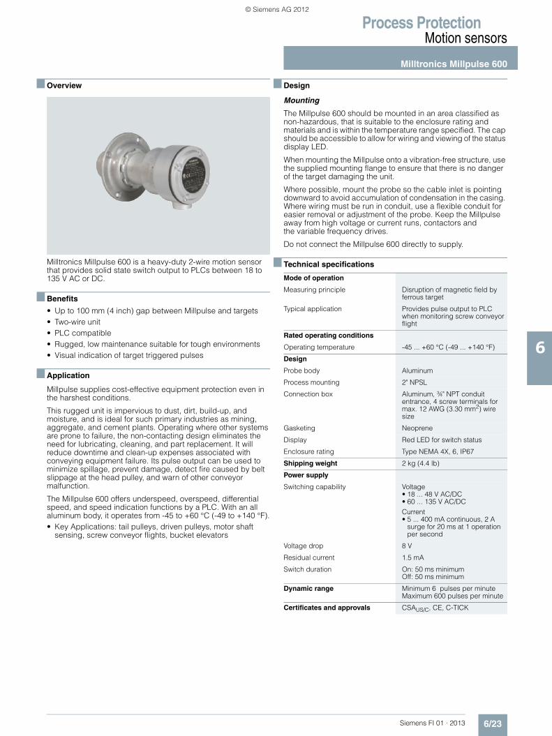
■ Overview
Milltronics Millpulse 600 is a heavy-duty 2-wire motion sensor that provides solid state switch output to PLCs between 18 to 135 V AC or DC.
■ Benefits
• Up to 100 mm (4 inch) gap between Millpulse and targets • Two-wire unit • PLC compatible • Rugged, low maintenance suitable for tough environments • Visual indication of target triggered pulses
■ Application
Millpulse supplies cost-effective equipment protection even in the harshest conditions.
This rugged unit is impervious to dust, dirt, build-up, and moisture, and is ideal for such primary industries as mining, aggregate, and cement plants. Operating where other systems are prone to failure, the non-contacting design eliminates the need for lubricating, cleaning, and part replacement. It will reduce downtime and clean-up expenses associated with conveying equipment failure. Its pulse output can be used to minimize spillage, prevent damage, detect fire caused by belt slippage at the head pulley, and warn of other conveyor malfunction.
The Millpulse 600 offers underspeed, overspeed, differential speed, and speed indication functions by a PLC. With an all aluminum body, it operates from -45 to +60 °C (-49 to +140 °F).• Key Applications: tail pulleys, driven pulleys, motor shaft
sensing, screw conveyor flights, bucket elevators
■ Design
Mounting
The Millpulse 600 should be mounted in an area classified as non-hazardous, that is suitable to the enclosure rating and materials and is within the temperature range specified. The cap should be accessible to allow for wiring and viewing of the status display LED.
When mounting the Millpulse onto a vibration-free structure, use the supplied mounting flange to ensure that there is no danger of the target damaging the unit.
Where possible, mount the probe so the cable inlet is pointing downward to avoid accumulation of condensation in the casing. Where wiring must be run in conduit, use a flexible conduit for easier removal or adjustment of the probe. Keep the Millpulse away from high voltage or current runs, contactors and the variable frequency drives.
Do not connect the Millpulse 600 directly to supply.
■ Technical specifications
Mode of operation
Measuring principle Disruption of magnetic field by ferrous target
Typical application Provides pulse output to PLC when monitoring screw conveyor flight
Rated operating conditions
Operating temperature -45 ... +60 °C (-49 ... +140 °F)
Design
Probe body Aluminum
Process mounting 2" NPSL
Connection box Aluminum, ¾" NPT conduit entrance, 4 screw terminals for max. 12 AWG (3.30 mm2) wire size
Gasketing Neoprene
Display Red LED for switch status
Enclosure rating Type NEMA 4X, 6, IP67
Shipping weight 2 kg (4.4 lb)
Power supply
Switching capability Voltage• 18 ... 48 V AC/DC • 60 ... 135 V AC/DC Current• 5 ... 400 mA continuous, 2 A
surge for 20 ms at 1 operation per second
Voltage drop 8 V
Residual current 1.5 mA
Switch duration On: 50 ms minimumOff: 50 ms minimum
Dynamic range Minimum 6 pulses per minuteMaximum 600 pulses per minute
Certificates and approvals CSAUS/C, CE, C-TICK
© Siemens AG 2012

Process ProtectionMotion sensors
Milltronics Millpulse 600
6/24 Siemens FI 01 · 2013
6
■ Dimensional drawings
Millpulse 600 mounting, dimensions in mm (inch)
Selection and Ordering data Order No.
Milltronics Millpulse 600Heavy-duty 2-wire motion sensor that provides solid state switch output to PLCs between 18 ... 135 V AC or DC.
Model
Millpulse 600, aluminum enclosure, ¾" NPT, CE, C-TICK, CSAUS/C approved (switches 18 ... 135 V AC/DC)
7MH7142-0AA10
Selection and Ordering data Order code
Further designs
Please add "-Z" to Order No. and specify Order code(s).
Manufacturer’s test certificate: According to EN 10204-2.2
C11
Acrylic coated, stainless steel tag [13 x 45 mm (0.5 x 1.75 inch)]: Measuring-point number/identification (max. 16 characters), specify in plain text
Y17
Operating Instructions Order No.
Millpulse 600, English 7ML1998-5DG02
Millpulse 600, German 7ML1998-5DG31
Millpulse 600, SpanishNote: The operating instructionsshould be ordered as a separate item on the order.This device is shipped with the Siemens Milltronics manual CD containing the complete operating inst-ructions library.
7ML1998-5DG22
Spare Parts
Locknut 7MH7723-1CR
Mounting flange 7MH7723-1CS
Motion cable gland adaptor kit 7MH7723-1JN
2" NPSL, aluminum probe
Mounting
Detail ADimensions
95 (3.75) dia.probe clearance hole
o.d.
13
3 (5
.25)
6 (0.24) dia. hole for 1/4...20 bolt on 114 (4.5) BCD, 4 places
6 (0.24) dia. hole for 1/4...20 bolt or drill and tap on 114 (4.5) BCD, 4 places
Mounting flange,see detail A
Locknut, plated
Casing gasket,neoprene
Casing, aluminum
Cap gasket, neoprene
Cap, aluminum with LED window
Terminal block
3/4" NPT Conduit
entrance
10-32 screw x 4
Ground screw
LED
226 (8.90)
127 (5.00)
60 (2
.38)
197 (7.76)
25 (1)2" NPSL
© Siemens AG 2012

Process ProtectionMotion sensors
Milltronics Millpulse 600
6/25Siemens FI 01 · 2013
6
■ Schematics
Millpulse 600 mounting, dimensions in mm (inch)
Interconnection
If the manufacturer of your PLC does not state that it is compatible with CENELEC 50040/36/37/38 electrical standards, then ensure that the switching current of the PLC input is above the residual current of the MillPulse. If your PLC does not meet the requirements, a resistor across the PLC inputs can be used to increase the switching current.
Operating voltage:Jumper in 18 ... 48 V AC/DCJumper out 60 ... 135 V AC/DC
PLC input/load
Jumper
Fuse
© Siemens AG 2012

Process ProtectionMotion sensors
SITRANS WM100
6/26 Siemens FI 01 · 2013
6
■ Overview
SITRANS WM100 is a heavy-duty zero-speed alarm switch. This non-contacting unit provides cost-effective equipment protection even in the harshest conditions.
■ Benefits
• Up to 100 mm (4 inch) gap between SITRANS WM100 and targets
• Rugged, low maintenance suitable for tough environments • 1 SPDT Form C relay contact • Provides cost-effective protection • Visual indication of target triggered pulse
■ Application
This rugged unit is impervious to dust, dirt, build-up and moisture and is ideal for such primary industries as mining, aggregate, and cement. Operating where other systems are prone to failure, the non-contacting design eliminates the need for lubricating, cleaning and part replacement. Downtime and clean-up expenses associated with conveying equipment failure are reduced by the SITRANS WM100. It alarms to minimize spillage, prevent extensive damage or even fire caused by belt slippage at the head pulley and warn against conveyor malfunction.
The SITRANS WM100 has built-in selectable start delays and 1 Form C relay contact. With an aluminum body, it operates from -40 to +60 °C (-40 to +140 °F).• Key Applications: tail pulleys, driven pulleys, motor shaft
sensing, screw conveyor flights, bucket elevators
■ Design
MountingThe WM100 probe should be mounted, using the supplied mounting flange, onto a vibration-free structure. The gap between the probe and the target should be sufficient such that there is no danger of the target damaging the probe. The maximum allowable gap is 100 mm (4 inch) from the face of the target to the face of the probe for 4.5 x 4.5 mm (3/16 x 3/16 inch) keyway. The WM100 is sensitive to lateral disturbances to its magnetic field. If the WM100 is responding to motion from an interfering target, move the WM100 or install a ferrous plate (steel) as a shield between the WM100 and the interfering target. Where possible, the probe should be mounted such that the cable inlet is pointing downward to avoid accumulation of condensation in the casing. Connection of the probe should be made via flexible conduit for easier removal or adjustment of the probe.
SITRANS WM100 mounting, dimensions in mm (inch)
■ Technical specifications
Mode of operation
Measuring principle Disruption of magnetic field by ferrous target
Typical application Monitors absence or presence of motion in harsh conditions
Output
Contact 1 SPDT Form C dry relay contact, rated 5 A at 250 V AC, fail-safe operation
Time delay Start up: 10 ... 14 seconds (5 ... 7 seconds with 12 ppm jumper installed)
Zero Speed (selected via a common jumper)
• 5 seconds ± 1 (minimum speed 10 ... 15 ppm) or
• 10 seconds ± 2 (minimum speed 5 ... 7.5 ppm)
Rated operating conditions
Operating temperature -40 ... +60 °C (-40 ... +140 °F)
Design
Probe body Aluminum
Process mounting 2" NPSL
Connection box Aluminum, ¾" NPT conduit entrance, 5 screw terminals plus grounding terminal for electrical connection, max. 12 AWG (3.30 mm2) wire size
Gasketing Neoprene
Display Red LED for verification of pulses
Enclosure rating Type NEMA 4x, 6, IP67
Dynamic range Minimum 6 or 12 pulses per minuteMaximum 3 000 pulses per minute
Shipping weight 2 kg (4.4 lb)
Power supply • 115 V AC/50 ... 60 Hz, 7 VA • 230 V AC/50 ... 60 Hz, 7 VA • ± 10 % of rated voltage
Certificates and approvals CSAUS/C, CE, C-TICK
Max. 100 (4)
© Siemens AG 2012
Process ProtectionMotion sensors
SITRANS WM100
6/27Siemens FI 01 · 2013
6
■ Dimensional drawings
SITRANS WM100 mounting, dimensions in mm (inch)
Selection and Ordering data Order No.
SITRANS WM100A heavy-duty zero-speed alarm switch that does not require a controller.
7MH7158 -
0 7A 0 0
Model115 V AC A230 V AC B
Selection and Ordering data Order code
Further designs
Please add "-Z" to Order No. and specify Order code(s).
Manufacturer's Test Certificate: According to EN 10204-2.2
C11
Acrylic coated, stainless steel tag [13 x 45 mm (0.5 x 1.75 inch)]: Measuring-point number/identifi-cation (max. 16 characters), specify in plain text
Y17
Operating Instructions Order No.
SITRANS WM100, English 7ML1998-5MW01
SITRANS WM100, GermanNote: The operating instructions should be ordered as a separate item on the order.This device is shipped with the Siemens Milltronics manual CD containing the complete operating instructions library.
7ML1998-5MW31
Locknut, for WM100 and Millpulse 600 7MH7723-1CR
Mounting flange, for WM100 and Millpulse 600 7MH7723-1CS
Motion cable gland adaptor kit 7MH7723-1JN
2" NPSL, aluminum probe body
Mounting
Detail ADimensions
95 (3.75) dia.probe clearance hole
o.d.
13
3 (5
.25)
6 dia. hole for 1/4...20 bolt on 114 (4.5) BCD, 4 places
6 dia. hole for 1/4...20 bolt or drill and tap on 114 (4.5) BCD, 4 places
Mounting flange,see detail A
Locknut, plated
Casing gasket,neoprene
Casing, aluminum
Cap gasket, neoprene
Cap, aluminum
3/4" NPT Conduit
entrance
Circuit card
10...32 screw x 4
226 (8.90)
127 (5.00)
60 (2
.38)
197 (7.76)
25 (1)2" NPSL
© Siemens AG 2012

Process ProtectionMotion sensors
SITRANS WM100
6/28 Siemens FI 01 · 2013
6
■ Schematics
SITRANS WM100 wiring
Notes:
1. Dry contacts shown in de-energized (alarm or shelf) state.
2. SITRANS WM100 is manufactured for either 115 or 230 V AC operation. Check WM100 nameplate for applicable voltage. Correct voltage must be supplied. Voltages lower than specified will result in an inoperative condition. Voltages higher than specified will severely damage unit.
3. For 5 second time delay and a minimum 12 ppm range, connect jumper across terminals 7 and 8. Without a jumper, the default is a 10 second time delay and a minimum 6 ppm range.
Not
e 3
Not
e 2
Not
e 1
Ground terminal for customer
connection
Detection indicator LED
Terminal circuit card
Terminal block for customer connection
7 5 4 3 2 18
12P
PM
5SEC
/
NO
NCL1
L2/N
50/6
0 H
Z 2.
5 VA
115/
230
VAC
1TBC
OM
© Siemens AG 2012