catalogue 2005/2006servus.hr/wp-content/uploads/2017/09/abicor-binzel-robo-3.pdf · cutting torches...
TRANSCRIPT

W e l d i n g & c u t t i n g b r o u g h t t o t h e p o i n t .
Catalogue 2005/2006
ROBO

Automatic weldingwith ABICOR BINZEL
Finally, periphery that completes the efficiency of a robot work cell.
In the late seventies ABICOR BINZEL started with the development of systemsfor robotic welding parallel to the introduction of the first robots in the automo-tive industry.
Today ABICOR BINZEL provides an effective product range of robot torchesand corresponding peripheral items which are in use around the world, 24hours a day.
Accompanying the product, a team of experts, both in our headquarter and inour subsidiaries, is always ready to assist with standard and custom-specificsolutions. Besides the installation, application and special training our after-sales service includes the support and optimization of the production process.Quick spare part supply and repairs are included.
To recognize and to co-create new innovative technological trends, is one ofour strong points.
Founded in 1945 Alexander Binzel Schweisstechnik GmbH & Co. KG specialized themselves in the development and production of welding and cutting torches for the GMAW, TIG and Plasma processes.
Numerous patented developments help shape the world of welding and cut-ting and set international standards.
The ABICOR BINZEL group is represented in more than 50 countries with over800 employees, 30 production and sales companies, as well as over 20exclusive partners.
Main production is located in the parent company in Buseck near Giessen, inDresden, as well as in the USA, Brazil, Switzerland, India and China.
The brand name ABICOR had been etablished in 1997 as an impression of acompany strategy that puts on innovation and globalization and that pursuesa clear brand policy.

Content
MIG/MAG Welding Torches MIG/MAG Welding Torch System “ABIROB®“ air-cooled Page 4–7
ABIROB® A360 / ABIROB® A500
MIG/MAG Welding Torch System “VTS-Interlock“ liquid-cooled Page 8–11
ROBO VTS 290 / ROBO VTS 500TS
MIG/MAG Welding Torch System “WH and WH-PP“ liquid-cooled Page 12–15
ROBO WH 242 D / ROBO WH 455 D / ROBO WH 652 D TS
TIG Welding Torches TIG Welding Torch System “ABITIG® WH“ liquid-cooled Page 16–19
ABITIG® WH 220 W / ABITIG® WH 400 W
Robot PeripheryRobot Mount “CAT2“ Page 20–21
“To stop collisions quickly …“
Torch Cleaning Station “BRS-CC“ Page 22–23
“Plug and Play …“
Front Injector “ABIROB® TMS-VI“ Page 24
“For the reduction of spatter adhesion …“
Wire Cutting Station “DAV“ Page 25
“The perfect cut ... “
Torch Neck Changing System “ATS-Rotor“ Page 26–27
“Work around the clock ... “
Welding Accessories Anti Spatter Spray, Wire Cleaning Set, Special Coolant, etc. Page 28
Cooling Recirculators WK 23 / WK 43 Page 29
3
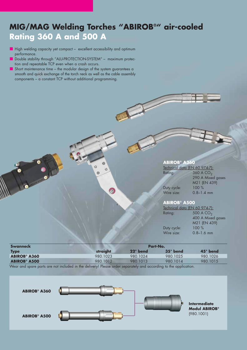
MIG/MAG Welding Torches “ABIROB®“ air-cooledRating 360 A and 500 A
Swanneck Part-No.Type straight 22° bend 35° bend 45° bendABIROB® A360 980.1023 980.1024 980.1025 980.1026ABIROB® A500 980.1012 980.1013 980.1014 980.1015
Wear and spare parts are not included in the delivery! Please order separately and according to the application.
ABIROB® A360Technical data (EN 60 974-7):Rating: 360 A CO2
290 A Mixed gases M21 (EN 439)
Duty cycle: 100 %Wire size: 0.8–1.4 mm
ABIROB® A500Technical data (EN 60 974-7):Rating: 500 A CO2
400 A Mixed gases M21 (EN 439)
Duty cycle: 100 %Wire size: 0.8–1.6 mm
High welding capacity yet compact – excellent accessibility and optimumperformance. Double stability through “ALU-PROTECTION-SYSTEM“ – maximum protec-tion and repeatable TCP even when a crash occurs.Short maintenance time – the modular design of the system guarantees asmooth and quick exchange of the torch neck as well as the cable assemblycomponents – a constant TCP without additional programming.
ABIROB® A360
ABIROB® A500
IntermediateModul ABIROB®
(980.1001)
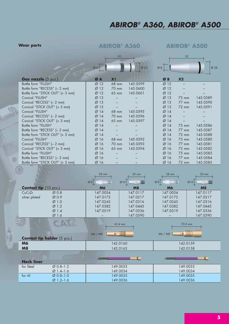
Wear parts
ABIROB® A360, ABIROB® A500
5
Ø A Ø 22 Ø 28Ø B
X1 X2
M6 / M8
63.4 mm
M6 / M8
70.0 mm
Ø10
30 mm
Ø 8
28 mm
Ø 8
28 mm
Contact tip holder (5 pcs.)M6 142.0160 142.0159M8 142.0163 142.0158
Gas nozzle (5 pcs.) Ø A X1 Ø B X2Bottle form “FLUSH“ Ø 12 68 mm 145.0599 Ø 12 – –Bottle form “RECESS“ (– 2 mm) Ø 12 70 mm 145.0600 Ø 12 – –Bottle form “STICK OUT“ (+ 3 mm) Ø 12 65 mm 145.0601 Ø 12 – –Conical “FLUSH“ Ø 13 – – Ø 13 75 mm 145.0589Conical “RECESS“ (– 2 mm) Ø 13 – – Ø 13 77 mm 145.0590Conical “STICK OUT“ (+ 3 mm) Ø 13 – – Ø 13 72 mm 145.0591Conical “FLUSH“ Ø 14 68 mm 145.0595 Ø 14 – –Conical “RECESS“ (– 2 mm) Ø 14 70 mm 145.0596 Ø 14 – –Conical “STICK OUT“ (+ 3 mm) Ø 14 65 mm 145.0597 Ø 14 – –Bottle form “FLUSH“ Ø 14 – – Ø 14 75 mm 145.0586Bottle form “RECESS“ (– 2 mm) Ø 14 – – Ø 14 77 mm 145.0587Bottle form “STICK OUT“ (+ 3 mm) Ø 14 – – Ø 14 72 mm 145.0588Conical “FLUSH“ Ø 16 68 mm 145.0592 Ø 16 75 mm 145.0580Conical “RECESS“ (– 2 mm) Ø 16 70 mm 145.0593 Ø 16 77 mm 145.0581Conical “STICK OUT“ (+ 3 mm) Ø 16 65 mm 145.0594 Ø 16 72 mm 145.0582Bottle form “FLUSH“ Ø 16 – – Ø 16 75 mm 145.0583Bottle form “RECESS“ (– 2 mm) Ø 16 – – Ø 16 77 mm 145.0584Bottle form “STICK OUT“ (+ 3 mm) Ø 16 – – Ø 16 72 mm 145.0585
ABIROB® A360 ABIROB® A500
Neck linerfor Steel Ø 0.8–1.2 149.0033 149.0033
Ø 1.4–1.6 149.0034 149.0034for Al Ø 0.8–1.0 149.0035 149.0035
Ø 1.2–1.6 149.0036 149.0036
Ø10
30 mm
Contact tip (10 pcs.) M6 M8 M6 M8CuCrZr Ø 0.8 147.0054 147.0117 147.0054 147.0117silver plated Ø 0.9 147.0172 147.0217 147.0172 147.0217
Ø 1.0 147.0245 147.0316 147.0245 147.0316Ø 1.2 147.0382 147.0445 147.0382 147.0445Ø 1.4 147.0519 147.0536 147.0519 147.0536Ø 1.6 – 147.0590 – 147.0590

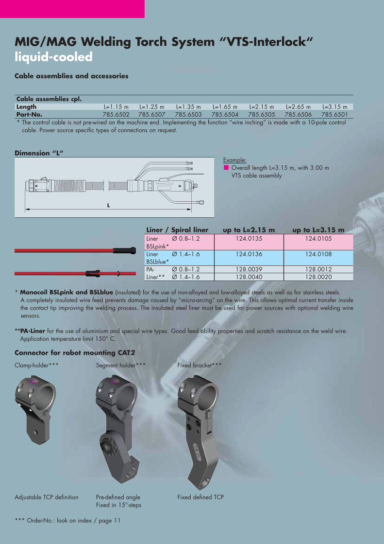
MIG/MAG Welding Torches “ABIROB®“ air-cooledCable assemblies and accessories
Cable assemblies cpl.Length L=1.15 m L=1.25 m L=1.35 m L=1.65 m L=2.15 m L=2.65 m L=3.15 mPart-No. 785.6002 785.6007 785.6003 785.6004 785.6005 785.6006 785.6001* The control cable is not pre-wired on the machine end. Implementing the function “wire inching” is made with a 10-pole control
cable. Power source specific types of connections on request.
Dimension “L“ Example:Overall length L=3.15 m, with 3.00 mABIROB® cable assembly
Mounting arm for robot mounting CAT2
Clamp-holder***
Adjustable TCP definition
*** Order-No.: look on index / page 7
Segment holder***
Pre-defined angle Fixed in 15°-steps
Fixed bracket***
Fixed defined TCP
L
Liner / Spiral liner up to L=2.15 m up to L=3.15 mLiner Ø 0.8–1.2 124.0135 124.0105BSLpink*Liner Ø 1.4–1.6 124.0136 124.0108BSLblue*PA- Ø 0.8–1.2 128.0039 128.0012Liner** Ø 1.4–1.6 128.0040 128.0020
* Monocoil BSLpink and BSLblue (insulated) for the use of non-alloyed and low-alloyed steels as well as for stainless steels. A completely insulated wire feed prevents damage caused by “micro-arcing” on the wire. This allows optimal current transferinside the contact tip improving the welding process. The insulated steel liner must be used for power sources with optional weldingwire sensors.
**PA-Liner for the use of aluminium and special wire types. Good feed ability properties and scratch resistance on the weld wire.Application temperature limit 150° C.

Mountingtype Torch Torch geometrie X Y Part-No.Clamp-holder ABIROB® A360 / A500 22° 366 0 780.0259
ABIROB® A360 / A500 35° 351 0 780.0259ABIROB® A360 / A500 45° 338 0 780.0259
Segment holder ABIROB® A360 / A500 22° variable in 15°-steps 780.0184ABIROB® A360 / A500 35° variable in 15°-steps 780.0184ABIROB® A360 / A500 45° variable in 15°-steps 780.0184
Fixed bracket ABIROB® A360 / A500 22° 350 0 780.0268ABIROB® A360 / A500 35° 350 0 780.0272ABIROB® A360 / A500 45° 350 0 780.0270
Other mountings on request.
7
ABIROB® A360, ABIROB® A500
Dimension sketch and alignment jigs
Alignment jigfor torch type for torch
geometrie Part-No.ABIROB® A360 / A500 0° / 22° / 45° 837.0500ABIROB® A360 / A500 35° 837.0514
ABIROB® A Shown with fixed bracket
15 m
m
X

MIG/MAG Welding Torch System “VTS-Interlock“ liquid-cooled
Swan neck Part-No.type 0° 22° 35° 45°ROBO VTS 290 – 785.5050 – 785.5091ROBO VTS 500TS 785.5101 785.5102 785.5103 785.5104Wear and spare parts are not included in the delivery! Please order sepa-rately and according to the application.
ROBO VTS 290Technical data (EN 60 974-7):Rating: 290 A Mixed gases
M21 (EN 439)Duty cycle: 100 %Wire size: 0.8–1.2 mm
“Ease of servicing, stable, flexible …“
VTS-Interlock – the welding torch system from ABICOR BINZEL for universal,heavy-duty MIG/MAG-Welding – enables a simple and flexible welding torchwith different overall sizes and geometries – for changing welding jobs.Standardized interfaces – identical on all VTS modules – guarantee an opti-mum interchange ability as well as a repeatable TCP installation at the robotor at another welding device.
Reproducible torch position thanks to the ”tongue and groove” interlock connection, easy-change torch neck and long-life cable assemblies which arequick to exchange, gives ease of maintenance when servicing the system.
Flexible adaptation on changing welding jobsStandardised interface – interlock connectionReproducible torch positionLiquid cooled up to 550 AWell proven and 100 % reliable
VTS cable assembly
“ReproducibleInterface“Interlock connection
ROBO VTS 500TSTechnical Data (EN 60 974-7):Rating: 500 A Mixed gases
M21 (EN 439)Duty cycle: 100 %Wire size: 0.8–1.6 mm
23.2 mm
M10x1
19 mm
9
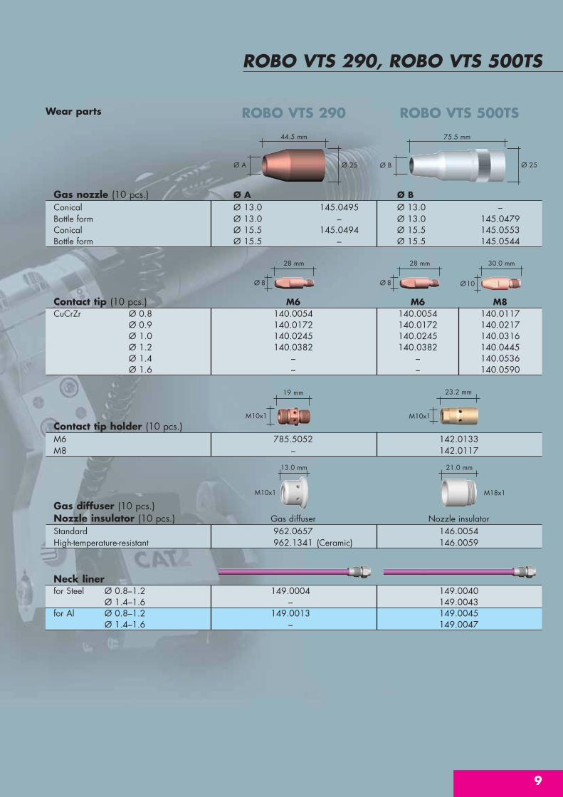
ROBO VTS 290, ROBO VTS 500TS
Gas nozzle (10 pcs.) Ø A Ø BConical Ø 13.0 145.0495 Ø 13.0 –Bottle form Ø 13.0 – Ø 13.0 145.0479Conical Ø 15.5 145.0494 Ø 15.5 145.0553Bottle form Ø 15.5 – Ø 15.5 145.0544
Wear parts ROBO VTS 290 ROBO VTS 500TS
Ø A Ø 25
44.5 mm 75.5 mm
Ø 8
28 mm
Ø 8
28 mm
Ø10
30.0 mm
Contact tip (10 pcs.) M6 M6 M8CuCrZr Ø 0.8 140.0054 140.0054 140.0117
Ø 0.9 140.0172 140.0172 140.0217Ø 1.0 140.0245 140.0245 140.0316Ø 1.2 140.0382 140.0382 140.0445Ø 1.4 – – 140.0536Ø 1.6 – – 140.0590
13.0 mm 21.0 mm
Ø 25Ø B
M18x1M10x1
M10x1
Contact tip holder (10 pcs.)M6 785.5052 142.0133M8 – 142.0117
Neck linerfor Steel Ø 0.8–1.2 149.0004 149.0040
Ø 1.4–1.6 – 149.0043for Al Ø 0.8–1.2 149.0013 149.0045
Ø 1.4–1.6 – 149.0047
Gas diffuser (10 pcs.)Nozzle insulator (10 pcs.) Gas diffuser Nozzle insulatorStandard 962.0657 146.0054High-temperature-resistant 962.1341 (Ceramic) 146.0059
MIG/MAG Welding Torch System “VTS-Interlock“ liquid-cooledCable assemblies and accessories
Cable assemblies cpl.Length L=1.15 m L=1.25 m L=1.35 m L=1.65 m L=2.15 m L=2.65 m L=3.15 mPart-No. 785.6502 785.6507 785.6503 785.6504 785.6505 785.6506 785.6501* The control cable is not pre-wired on the machine end. Implementing the function “wire inching” is made with a 10-pole control
cable. Power source specific types of connections on request.
Dimension “L“Example:
Overall length L=3.15 m, with 3.00 m VTS cable assembly
L
Connector for robot mounting CAT2
Clamp-holder***
Adjustable TCP definition
*** Order-No.: look on index / page 11
Segment holder***
Pre-defined angle Fixed in 15°-steps
Fixed bracket***
Fixed defined TCP
Liner / Spiral liner up to L=2.15 m up to L=3.15 mLiner Ø 0.8–1.2 124.0135 124.0105BSLpink*Liner Ø 1.4–1.6 124.0136 124.0108BSLblue*PA- Ø 0.8–1.2 128.0039 128.0012Liner** Ø 1.4–1.6 128.0040 128.0020
* Monocoil BSLpink and BSLblue (insulated) for the use of non-alloyed and low-alloyed steels as well as for stainless steels. A completely insulated wire feed prevents damage caused by “micro-arcing” on the wire. This allows optimal current transfer insidethe contact tip improving the welding process. The insulated steel liner must be used for power sources with optional welding wiresensors.
**PA-Liner for the use of aluminium and special wire types. Good feed ability properties and scratch resistance on the weld wire. Application temperature limit 150° C.

11
ROBO VTS 290, ROBO VTS 500TS
Dimension sketch and alignment jigs
Alingment jigfor torch type for torch
geometrie Part-No.ROBO VTS 290 0° / 45° 837.0452ROBO VTS 500TS 0° / 22° /45° 837.0464ROBO VTS 500TS 35° 837.0466
Mountingtype Torch Torch geometrie X Y Part-No.Clamp-holder VTS 290 22° 354 0 780.0259
VTS 290 45° 332 0 780.0259VTS 500TS 22° 354 0 780.0259VTS 500TS 45° 326 0 780.0259
Segment holder VTS 290 22° variable in 15°-steps 780.0184VTS 290 45° variable in 15°-steps 780.0184VTS 500TS 22° variable in 15°-steps 780.0184VTS 500TS 45° variable in 15°-steps 780.0184
Fixed bracket VTS 500TS 22° 350 0 780.0278VTS 500TS 45° 350 0 780.0282
Other mountings on request.
ROBO VTS Shown with segment holder
15 mm
X
Y
MIG/MAG Welding Torch System “WH and WH-PP“liquid-cooled
Swan neck Part-No.Type 0° 22° 45°ROBO WH 242 D 962.1314 962.1315 962.1316ROBO WH 455 D 962.0767 962.0768 962.0769ROBO WH 652 D TS 962.1353 962.1365 962.1366Wear and spare parts are not included in the delivery! Please order sepa-rately according to the application.
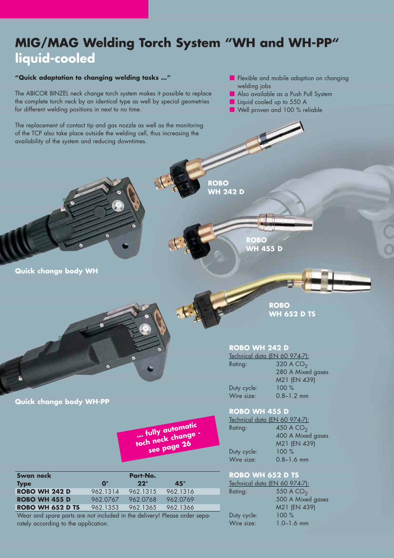
ROBO WH 242 DTechnical data (EN 60 974-7):Rating: 320 A CO2
280 A Mixed gasesM21 (EN 439)
Duty cycle: 100 %Wire size: 0.8–1.2 mm
ROBO WH 455 DTechnical data (EN 60 974-7):Rating: 450 A CO2
400 A Mixed gasesM21 (EN 439)
Duty cycle: 100 %Wire size: 0.8–1.6 mm
ROBO WH 652 D TSTechnical data (EN 60 974-7):Rating: 550 A CO2
500 A Mixed gasesM21 (EN 439)
Duty cycle: 100 %Wire size: 1.0–1.6 mm
“Quick adaptation to changing welding tasks …”
The ABICOR BINZEL neck change torch system makes it possible to replacethe complete torch neck by an identical type as well by special geometries for different welding positions in next to no time.
The replacement of contact tip and gas nozzle as well as the monitoring of the TCP also take place outside the welding cell, thus increasing the availability of the system and reducing downtimes.
Flexible and mobile adaption on changing welding jobsAlso available as a Push Pull SystemLiquid cooled up to 550 AWell proven and 100 % reliable
Quick change body WH-PP
Quick change body WH
ROBOWH 242 D
ROBOWH 455 D
ROBOWH 652 D TS
… fully automatic
toch neck change -
see page 26

Gas nozzle (10 pcs.) Ø A Ø B Ø CConical Ø 15.5 145.0090 Ø 15.5 145.0089 Ø 18.0 145.0574Conical Ø 13.0 145.0135 Ø 13.0 145.0134 Ø 21.5 145.0575
ROBO WH 242 D, ROBO WH 455 D, ROBO WH 652 D TS
13
Ø10
30.0 mm
Ø 8
28.0 mm
Ø 8
28.0 mm
Wear parts ROBO WH 242 D ROBO WH 652 D TSROBO WH 455 D
Ø C Ø30
77.0 mm
23.5 mm
M9x1
28.0 mm
M12x1
14.5 mm
Bi 8/24
27.0 mm 21.0 mm 16.0 mm
ØB Ø 25
67.5 mm
ØA Ø 21
62.0 mm
Ø 12
35.0 mm
Neck linerfor Steel Ø 0.8–0.9 149.0073 149.0072 –0° / 22° Ø 1.0–1.2 149.0077 149.0076 149.0080
Ø 1.4–1.6 – 149.0081 149.0083for Steel Ø 0.8–0.9 149.0075 149.0074 –45° Ø 1.0–1.2 149.0079 149.0078 149.0080
Ø 1.4–1.6 – 149.0082 149.0083for Al Ø 0.8–1.0 149.0085 149.0084 149.00880° / 22° Ø 1.2–1.6 149.0090 149.0089 149.0093for Al Ø 0.8–1.0 149.0087 149.0086 149.008845° Ø 1.2–1.6 149.0092 149.0091 149.0093
Contact tip (10 pcs.) M6 M6 M8 M10CuCrZr Ø 0.8 140.0054 140.0054 140.0117 –
Ø 0.9 140.0172 140.0172 140.0217 –Ø 1.0 140.0245 140.0245 140.0316 140.0348Ø 1.2 140.0382 140.0382 140.0445 140.0481Ø 1.4 – – 140.0536 140.0547Ø 1.6 – – 140.0590 140.0616
M22x1M18x1M16x1
Contact tip holder (10 pcs.)M6 142.0149 142.0123 –M8 – 142.0122 –M10 – – 142.0145
Nozzle insulator (10 pcs.)Standard 146.0066 146.0054 146.0056High-temperature-resistant – 146.0059 146.0069 (Ceramic)

MIG/MAG Welding Torch System “WH and WH-PP“liquid-cooledCable assembly
Cable assembly “WH“ cpl.Length L=1.05 m L=1.15 m L=1.25 m L=1.45 m L=1.65 m L=2.15 m L=2.65 m L=3.15 mPart-no. 965.2001 965.2002 965.2003 965.2004 965.2005 965.2006 965.2007 965.2008
Cable assembly “WH-PP“ cpl. (gear ratio i=17,1:1 / Motor 42 V DC*)Length L=1.10 m L=1.50 m L=1.70 m L=2.20 m L=2.70 m L=3.20 mPart-no. 965.4014 965.4015 965.4016 965.4001 965.4002 965.4003* The control cable is not pre-wired on the machine end. Implementing the function “wire inching” is made with a 10-pole control
cable. Power source specific types of connections and lengths of more than 3,20 m on request.
Dimension “L“Example:
Overall length L=3.15 m, with 3.00 m ROBO WH cable assembly Overall length L=3.20 m, with 3.00 m ROBO WHPP cable assembly
Drive Roll for WH-PP Al (U-Nut) Universal (V-Nut)Ø 0.8 961.0017 961.0269Ø 0.9 961.0056 961.0270Ø 1.0 961.0018 961.0227Ø 1.2 961.0019 961.0228Ø 1.4 – 961.0279Ø 1.6 961.0020 961.0267
L
Liner / Spiral Liner up to L=2.15 m up to L=3.20 mLiner Ø 0.8–1.2 124.0135 124.0105BSLpink*Liner Ø 1.4–1.6 124.0136 124.0108BSLblue*PA- Ø 0.8–1.2 128.0039 128.0012Liner** Ø 1.4–1.6 128.0040 128.0020
* Monocoil BSLpink and BSLblue (insulated) for the use of non-alloyed and low-alloyed steels as well as for stainless steels. A completely insulated wire feed prevents damage caused by “micro-arcing” on the wire. This allows optimal current transfer insidethe contact tip improving the welding process. The insulated steel liner must be used for power sources with optional welding wiresensors.
**PA-Liner for the use of aluminium and special wire types. Good feed ability properties and scratch resistance on the weld wire. Application temperature limit 150° C.

ROBO WH 242 D, ROBO WH 455 D, ROBO WH 652 D
15
Dimension Sketch and alignment jigs
ROBO WH Shown with standard holder
Alignment jigfor torch type for torch
geometrie Part-No.ROBO WH 242 D 0°/22°/45° 837.0020ROBO WH 455 D 0°/22°/45° 837.0020ROBO WH 652 D 0°/22°/45° 837.0099
Mountingtype Torch Torch geometrie X Y Part-No.WH standard WH 242 D 22° 354 0 960.0026adjustable WH 242 D 45° 349 0 960.0026
WH 455 D 22° 354 0 960.0026WH 455 D 45° 349 0 960.0026WH 652 D TS 22° 410 0 960.0026WH 652 D TS 45° 382 0 960.0026
Segment holder WH 242 D 22° variable in 15°-steps 780.0146WH WH 242 D 45° variable in 15°-steps 780.0146
WH 455 D 22° variable in 15°-steps 780.0146WH 455 D 45° variable in 15°-steps 780.0146WH 652 D TS 22° variable in 15°-steps 780.0146WH 652 D TS 45° variable in 15°-steps 780.0146
15 mm
X
Y

TIG Welding Torch System“ABITIG® WH“ liquid-cooled
Swan neck Part-No.Type 0° 45° 70° 90°ABITIG® WH 220 W – – 781.1001 –ABITIG® WH 400 W 781.0504 781.0507 781.0501 781.0510Wear and spare parts are not included in the delivery! Please order sepa-rately according to the application.
ABITIG® WH 220 WTechnical data (EN 60 974-7):Rating: 220 A DC
160 A ACDuty cycle: 100 %Wire size: 1.0–3.2 mm
ABITIG® WH 400 WTechnical data (EN 60 974-7):Rating: 400 A DC
280 A ACDuty cycle: 100 %Wire size: 1.6–4.8 mm
“Quick, safe and failure-free ...“
The ABITIG® WH-Welding-Torch-System fromABICOR BINZEL for TIG soldering and TIG weldingoffers a high process stability for joining variousmaterials.Preset tungsten electrodes, reproducible torch changes and maintenance service outside the robotcell guarantees constant high quality and continuousoperation of the system.With two sizes and different geometries, the TIG wel-ding torch system ABITIG WH covers nearly all appli-cations in the field of automated TIG welding and issuitable for welding even the most complicated parts.Also available as Push- or Push-Pull-0ption with coldwire feeding.
Flexible adaption on changing welding jobsAdjustable tungsten electrodesReproducible torch positionCold wire feeding optionalLiquid cooled up to 550 AWell proven and 100 % reliable
ABITIG®
WH 400 W
ABITIG®
WH 400 W
… fully automatic
toch neck change -
see page 26

17
ABITIG® WH 220 W, ABITIG® WH 400 W
Insulator 776.1043 775.1043
Back cap776.0053 967.1351
Wear parts ABITIG® WH 220 W ABITIG® WH 400 W
26 mm
36 mm
33 mm 47 mm
37 mm
52 mm
56 mm35 mm
Electrode holder / Electrode holder Gas diffuser Electrode holder Gas diffuserGas diffuser (5 pcs.) (5 pcs.) (5 pcs.) (5 pcs.)Ø 1.0 mm 776.0061 776.0171 – –Ø 1.6 mm 776.0062 776.0172 775.0062 773.0172Ø 2.0 mm 776.0067 776.0177 775.0067 773.0177Ø 2.4 mm 776.0063 776.0173 775.0063 773.0173Ø 3.2 mm 776.0064 776.0174 775.0064 773.0174Ø 4.0 mm – – 775.0065 773.0175Ø 4.8 mm – – 775.0066 773.0176
Gas nozzle, ceramic (10 pcs.)Ø 6.5 mm 777.0081 –Ø 7.5 mm – 775.0081Ø 8.0 mm 777.0082 –Ø 9.5 mm 777.0083 –Ø 10.0 mm – 775.0082Ø 11.0 mm 777.0084 –Ø 13.0 mm – 775.0083Ø 15.0 mm – 775.0084
Gas nozzle, ceramic (10 pcs.)Ø 6.5 mm 777.2171 –Ø 7.5 mm – 775.2171Ø 8.0 mm 777.2172 –Ø 9.5 mm 777.2173 –Ø 10.0 mm – 775.2172Ø 11.0 mm 777.2174 –Ø 13.0 mm – 775.2173Ø 15.0 mm – 775.2174

TIG Welding Torch System “ABITIG® WH“ liquid-cooledCable assemblies and options
Cable assemblies cpl. Part-No.version L=4.00 m* L=6.00 m* L=8.00 m*BCS-00 Standard 781.0526 781.0527 781.0528BCS-03 781.0517 781.0518 781.0519BCS-06 781.0523 781.0524 781.0525BCS-08 781.0520 781.0521 781.0522*Other versions on request.
BCS-00
BCS-03 BCS-06 BCS-08
Cold wire feedingDescription Version / Specification Part-No.Cold wire feeding cpl. incl. guide tube and -nozzle 967.0320Guide tube ABITIG® WH 220 W 70 967.0327Guide tube ABITIG® WH 400 W 0 967.0326Guide tube ABITIG® WH 400 W 45 967.0328Guide tube ABITIG® WH 400 W 70 967.0325Guide tube ABITIG® WH 400 W 90 967.0325Guide nozzle for wire size 0.6 967.0335Guide nozzle for wire size 0.8 967.0329Guide nozzle for wire size 1.0 967.0330Guide nozzle for wire size 1.2 967.0331Guide nozzle for wire size 1.6 967.0332Wire conduit cpl. 4.00 m length 781.0514Wire conduit cpl. 6.00 m length 781.0515Wire conduit cpl. 8.00 m length 781.0516
Push-Pull OptionDescription Version / Specification Part-No.Push-Pull Option i=34.3:1 for Δ V = 0.2 – 5.0 m/min 963.0253cpl. with ENCODER-Motor incl. Drive rollsDrive roll for wire size 0.6 961.0268Drive roll for wire size 0.8 961.0269Drive roll for wire size 1.0 961.0227Drive roll for wire size 1.2 961.0228Drive roll for wire size 1.6 961.0267
Ignition aidDescription Version / Specification Part-No.Ignition aid cpl. ABITIG® WH 220 W 967.0102Ignition aid cpl. ABITIG® WH 400 W 967.0101
BracketDescription Version / Specification Part-No.Bracket Connector for CAT2 963.0007
Options
19
ABITIG® WH 220 W, ABITIG® WH 400 W
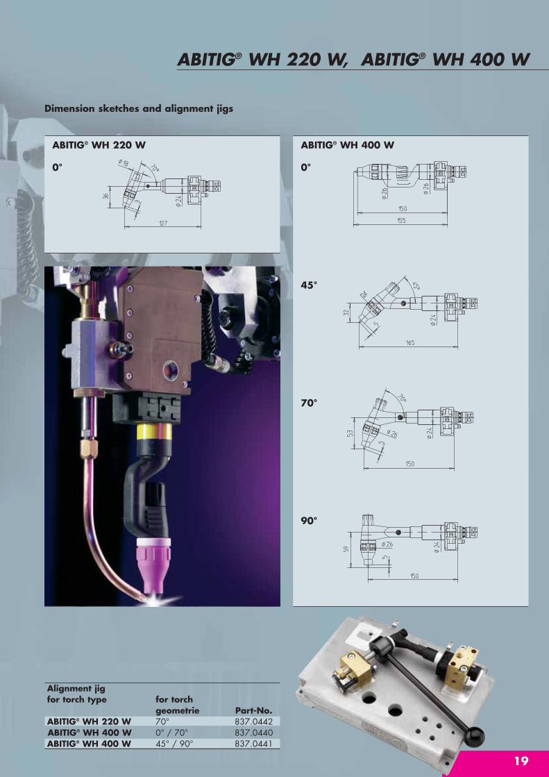
Dimension sketches and alignment jigs
0°
ABITIG® WH 220 W
0°
45°
70°
90°
ABITIG® WH 400 W
Alignment jigfor torch type for torch
geometrie Part-No.ABITIG® WH 220 W 70° 837.0442ABITIG® WH 400 W 0° / 70° 837.0440ABITIG® WH 400 W 45° / 90° 837.0441

Robot mount “CAT2“ – for safer welding“To stop collisions quickly …“Faster robots, increasing dynamics, and thinnermetals with complex outlines can lead to a collisionof the torch to the workpiece. The CAT2 robotmount protects against collisions with optimizedresetting accuracy. Safety switch sensitivity can beuser adjusted.The wide range of accessories gives the CAT2 amultitude of mounts and extensions for realisingthe desired TCP.
Technical data:Robot mount “CAT2“Dimensions: Corner width 75 mm; Across flats 65 mm;
height 87 mm (robot flange > release flange)Weight: approx. 630 g
approx. 850 g (incl. tool holder and flange)Release force: please look at the chartMax. excursion: in X- and Y-plane against each spring
10 - 14°; in Z-plane against each spring 4 - 8 mm
Instantaneous Through Z-axis 0.5° - 1°; Deviation through stop release: X- and Y-direction approx. 1.5°; Deviation
through Z-direction approx. 0.5 - 1 mmReapeatibility: < +/- 0.04 mm (at 300 mm stand-off from
robot flange)Safety switch: 24 V DC, max. 100 mA
Variable deflection in every position.Instantaneous stop in case of collision. Precise repeatability minimizes downtime.Precise switch points by innovative switching-time response.Perfect for ultrahigh accuracy, light gauge sheet metal operations.Easy to service by visual multi-functional display for a quick error analysis.Covered screws for quick service. Adaptable to all robot types and handling systems – by adapter flange(plastic or aluminium).

21
Robot mount “CAT2“
Robot mount CAT2Description Part-No.Robot mount CAT2 (S) cpl. 780.2131Robot mount CAT2 (M) cpl. standard 780.2100Robot mount CAT2 (L) cpl. 780.2121Robot mount CAT2 (LL) cpl. 780.2118Robot mount CAT2 (XL) cpl. 780.2132Alignment jig cpl. 780.2019
Adapter flangeDescription Plastic Aluminium
type typePart-No. Part-No.
ISO 9409-1-A31.5 780.0632 780.0532ISO 9409-1-A40 780.0604 780.0504ISO 9409-1-A50 780.0603 780.0503ISO 9409-1-A63 780.0614 780.0514ISO 9409-1-A80 780.0607 780.0507ISO 9409-1-A100 780.0649 780.0549ISO 9409-1-A125 780.0630 780.0530Adapter flanges can be delivered for all common welding robots.
Please indicate the type of robot and model of robot.
Attention! Due to insulation reasons always apply plastic adapter flangewhen using MIG/MAG welding torches of the ABIROB® A product series.
Deflection of the CAT2:- Collision in direction of the X- or Y-axis.- Rotation around the Z-axis.- Collision in direction of the Z-axis.The release torque is defined by the spring types,depending on application and weight of the torch.There are five spring types available – see table.
Release force (N)Spring- Release force Release forcetype X-, Y-axis (N) Z-axis (N)S 46 475M 80 535L 85 925LL 130 1325XL 150 1540
ABIROB® A 360 with Robot mount CAT2

... the complete solution for reliable automatic servicing of the torch neck. Installed quickly and easily, or“Plug and Play ...”, the compact torch cleaning station BRS-CC means top reliability. Combined in asingle station, the 3 systems guarantee optimally timed processes and an increase in available plant floorspace. A number of other features such as mounting stand and drip pan reduce installation costs.
Torch cleaning station “BRS-CC“ “Plug and Play …“
1. Torch cleaning stationPrecise and effective cleaning for almost allrobot welding torches.Proven and trusted cutter principle, suitableeven for heavy spatter adhesion.3-point clamping of the gas nozzle fixes thetorch in place during the cleaning process.
2. Spraying unit “TMS-VI“Direct, economical spraying of anti-spatter fluidreduces welding spatter adhesion and extendsthe servicing intervals.Clean environment thanks to encapsulatedspraying nozzle and collecting pan for dirtyresidual oil.
Simple disposal of residual oil and replenish-ment of the anti-spatter agent by simply exchangingthe bottles.
3. Wire cutting fixture „DAV“The combined clamping and shearing action guarantees precise cutting quality and ensuresoptimum arc-start properties as well as exact TCPmeasurement.Long service life thanks to sturdy design.
1
2
3
Torch cleaning station “BRS-CC“ (incl. stand, drip pan and spraying unit)Description Part-No.Torch cleaning station “BRS-CC“ with “DAV“ 831.0490Torch cleaning station “BRS-CC“ without “DAV“ 831.0550

23
Torch cleaning station “BRS-CC“
Clamping block and reamer
General dataWeight: approx. 16 kgAmbient temperature + 5°C up to + 50°CPneumatic connection – manifold blockCompressed air supply outlet: G 1/4Inside width: min. Ø 6 mmNominal pressure: 6 barOperating pressure: 6-8 barElectrics – terminal block4 inlets for triggering the 5/2-control valvesControl voltage: 24 V DCPower demand: 4.5 W1 inductive proximity switch a-contact (pnp)Operating voltage: 10-30 V DCTolerated residual ripple: Vss < 10%Continuous current: 200 mA max.Current consumption: approx. 4 mA (24 V)Voltage drop: approx. 1.2 V (200 mA)
Technical data: Cleaning stationPneumatic motor (nominal speed)- with lubricated air: approx. 650 rpm- with non-lubricated air: approx. 550 rpmAir consumption: approx. 380 L/Min.Injection unitCapacity of the bottle: 1 litreWire cutting stationCutting rate at 6 bar- Solid wire: up to 1.6 mm- Flux-cored wire: up to 3.2 mmCutting time: 0.5 sec.
For torch type with Outer-Ø / Length with Clamping block Reamergas nozzle nominal-Ø (mm) (mm) contact tip Part-No. Part-No.
ABIROB® A 360 145.0599 22.0 / 12.0 68.0 M6 / Ø 8 831.0371 831.0604ABIROB® A 360 145.0600 22.0 / 12.0 70.0 M6 / Ø 8 831.0371 831.0604ABIROB® A 360 145.0601 22.0 / 12.0 65.0 M6 / Ø 8 831.0371 831.0604ABIROB® A 360 145.0595 22.0 / 14.0 68.0 M6 / Ø 8 831.0371 831.0575ABIROB® A 360 145.0596 22.0 / 14.0 70.0 M6 / Ø 8 831.0371 831.0575ABIROB® A 360 145.0597 22.0 / 14.0 65.0 M6 / Ø 8 831.0371 831.0588ABIROB® A 360 145.0592 22.0 / 16.0 68.0 M6 / Ø 8 831.0371 831.0487ABIROB® A 360 145.0593 22.0 / 16.0 70.0 M6 / Ø 8 831.0371 831.0487ABIROB® A 360 145.0594 22.0 / 16.0 65.0 M6 / Ø 8 831.0371 831.0589ABIROB® A 500 145.0589 28.0 / 13.0 75.0 M6 / Ø 8 831.0318 831.0180ABIROB® A 500 145.0590 28.0 / 13.0 77.0 M6 / Ø 8 831.0318 831.0180ABIROB® A 500 145.0591 28.0 / 13.0 72.0 M6 / Ø 8 831.0318 831.0169ABIROB® A 500 145.0586 28.0 / 14.0 75.0 M6 / Ø 8 831.0318 831.0592ABIROB® A 500 145.0587 28.0 / 14.0 77.0 M6 / Ø 8 831.0318 831.0592ABIROB® A 500 145.0588 28.0 / 14.0 72.0 M6 / Ø 8 831.0318 831.0593ABIROB® A 500 145.0580 28.0 / 16.0 75.0 M8 / Ø 10 831.0318 831.0488ABIROB® A 500 145.0581 28.0 / 16.0 77.0 M8 / Ø 10 831.0318 831.0488ABIROB® A 500 145.0582 28.0 / 16.0 72.0 M8 / Ø 10 831.0318 831.0591ABIROB® A 500 145.0583 28.0 / 16.0 75.0 M8 / Ø 10 831.0318 831.0488ABIROB® A 500 145.0584 28.0 / 16.0 77.0 M8 / Ø 10 831.0318 831.0488ABIROB® A 500 145.0585 28.0 / 16.0 72.0 M6 / Ø 8 831.0318 831.0591VTS 290 145.0495 25.0 / 13.0 44.5 M6 / Ø 8 831.0316 831.0169VTS 290 145.0494 25.0 / 15.5 44.5 M6 / Ø 8 831.0316 831.0576VTS 500TS 145.0553 25.0 / 15.5 75.5 M8 / Ø 10 831.0316 831.0485VTS 500TS 145.0479 25.0 / 13.0 75.5 M8 / Ø 10 831.0316 831.0368VTS 500TS 145.0544 25.0 / 15.5 75.5 M8 / Ø 10 831.0316 831.0023WH 242 D 145.0135 21.0 / 13.0 62.0 M6 / Ø 8 831.0314 831.0564WH 242 D 145.0090 21.0 / 15.5 62.0 M6 / Ø 8 831.0314 831.0563WH 455 D 145.0134 25.0 / 13.0 67.5 M8 / Ø 10 831.0316 831.0413WH 455 D 145.0089 25.0 / 15.5 67.5 M8 / Ø 10 831.0316 831.0023WH 652 D TS 145.0574 30.0 / 18.0 77.0 M10 / Ø 12 831.0319 831.0162WH 652 D TS 145.0575 30.0 / 21.5 77.0 M10 / Ø 12 831.0319 831.0547

Front injector „ABIROB® TMS-VI““For the reduction of spatter adhesion …“With the front injector ABIROB® TMS-VI thecleaned torch is sprayed with anti spatter fluidwhich minimizes built-up of welding spatter. The specially developed spray nozzle enables ahighly efficient application of the anti spatter fluid.
Front injector ABIROB® TMS-VI – this new concept enables a smooth and eco-nomical spraying of the anti spatter fluid to the front of the welding torch.
The advantages at a glance:Effective and economical anti spatter spray supply to nozzle interior and nozzle edge.Covered injector nozzle and extra bottle for used oil improves working safety and ensures environmental friendly use.Trouble-free refilling of the anti spatter fluid, simply by swapping the bottle.Trouble-free dispose of used oil by swapping the bottle.Installation set for a user-friendly installation of the unit.
Technical data:PneumaticsWorking pressure: 5 – 10 barInternal dia.: ø 4 mm5/2 solenoid valveAir connection: G 1/8“Nonimal flow: approx. 650 l/min.Input signal: 24 V DC
I max. ≤ 1.1 AI nom. = 220 mA
Front injector TMS-VIDescription Part-No.Front injector TMS-VI cpl. 830.1110Solenoid valve pilot-controlled (NW 10) 24 V DC / 42 V AC 832.0005Anti-spatter-fluid 1 Litre 192.0056Anti-spatter-fluid 5 Litre 192.0052Anti-spatter-fluid 20 Litre 192.0048Anti-spatter-fluid 200 Litre 192.0046

25
Wire cutting station “DAV““The perfect cut ... “The wire cutting station DAV in MIG/MAG robotic welding is an essentialrequirement to guarantee a consistent wire stick-out, and clean end of the wireas well as better capacity of arc-start due to the cutting of the welding balland oxides formed at the end of the wire.
The ABICOR BINZEL wire cutting station DAVstands for:
Defined wire length as requirement for the automatic TCP measurement.Precise and reliable cutting quality even withhard or thick wires.High durability and longevity of the blades.Wire clamping function for the wire removal in connection with the ATS-Rotor.
Wire cutting station “DAV“Description Part-No.Wire cutting station “DAV“ cpl. 839.0020Replacement knife 839.0024Replacement static blade 839.0026Extension set consisting of: 5/2-way-valve, plug, connectors, 839.0035
pneumatic hose (1m), silencer
Technical data:Wire cutting station “DAV“Working pressure: 6 – 8 barAir connection: ID 4.0 mmCutting range at 6 bar: Solid wire 1.6 mm
Cored wire 3.2 mmWeight: 2700 gExtension setWorking pressure: 6 – 8 bar Air connection: G 1/8“Control requirements: 24 V DC
I max. = 1.1 A peakI ave. = 220 mA cont.
Weight: 265 g

“ATS-Rotor“ – the intelligent system for the automaticexchange of the WH torch necks (MIG and TIG) “Work around the clock …“
Integrated into the robot cell the ATS rotor can be equipped with up to fivereplacement torch necks. The factory standardized interface enables the appli-cation of MIG/MAG- and TIG-neck changes. Depending on the welding appli-cation the robot accesses the neck change system cyclically and event-oriented(for example a stuck torch) to exchange a torch neck with a new torch neck.
Only after exchanging all five change necks (in a cyclical exchange) a manualaction needs to be done by equipping the ATS rotor with newly serviced necks.Exchanging of the spare and wear parts on the torch necks is performed out-side the robot cell, while the production process continues.
This means to the user an enormous potential (up to the fivefold) of the availabi-lity of the unit (referring to the maintenance service at the torch neck).
System for an automatic torch neck changing, unique world wideSimple aluminium cast frame with low-maintenance pneumatic cylinderIntegrated SPS (industry standard) for the connection at the robot control systemEasy to install and use
Technical data:Dimensions: 660 mm width,
416 mm height (plus 100 mm lift)– for more detailed informationplease refer to separate data-sheet
Weight: App. 31 kgAmbient temp.: 5°- 50°CProtection class: I (DIN 57 106)Pneumatic dataConnection: G1/4"Internal dia: min. Ø 6 mmRated pressure: 6 barConsumption per 1,5 lchange: Electrical dataOperating voltage: 24 V DCPower consumption: 50 WW Max. ripple: Vss<10%

27
“ATS-ROTOR“
The robot controls the ATS-Rotor through theuse of 24V digital inputsand outputs. Each individual changecycle is performed auto-matically under the con-trol of an integrated PLC.
Functioning
1 Robot docks WH neck into ATS-Rotor changestation.
2 Neck release mechanism is engaged and wire iscut inside the torch body.
3 The change neck is taken off by the downwardmovement of the rotor plate. Quick release val-ves in the water channels avoid leaking of thecoolant.
4 Rotor carousel rotates a replacement neck intoposition.
ATS-RotorDescription Part-No.ATS-Rotor with SPS 840.3300ATS-Rotor without SPS 840.3400
5 Replacement neck is locked into position. All supply connectors are automatically made,robot moves out of change station and continues.

5
5 Special coolantBTC-15The special coolant from BINZEL protect down to minus 10°Cfor all liquid weldingand cutting facilities.Part-No.:5 litre 192.011020 litre 192.0111200 litre 192.0112
6 SpigotPart-No.: 192.0109for 200 litre barrel
9 SpannerPart-No.: 191.0001
10 Multiple spannerPart-No.: 191.0015
11 Universal spannerPart-No.: 750.0125
12 Electrode spannerPart-No.: 743.0064
9
10
11
12
7 Sharpener for collet core liner Part-No.: 191.0064
8 Hose cutterPart-No.: 191.0062
7
8
6
Welding accessories
1
To achieve thebest results …
1 Anti spatter fluid, silicon free, protect for spatterPart-No.:1litre 192.00565 litre 192.005220 litre 192.0048200 litre 192.0046
2
3
2 Gas flow meterPart-No.: 191.0003
3 Wire cleaning setred for steelPart-No.: 193.0001white for AlPart-No.: 193.0002
… one of the things which will help you to achieve the best results in the welding process is to use profes-sional accessories. When ideally tailored to the task, they provide the basis for operational safety and longservice life. High-quality welding accessories increase the output and reliability of your torch. To achieve opti-mum results, don’t leave anything to chance. Rely on original welding accessories from ABICOR BINZEL.
Wire cleaning feltred for steel (25 pcs.)Part-No.: 193.0003white for Al (25 pcs.)Part-No.: 193.0004
4 ClampPart-No.: 193.0007
4
13 Cable assembly supportPart-No.: 191.0039
14 Protective cover1.20 m (Ø = 40.0 mm with Velcro fasteningPart-No.: 191.0040
w./o. fig.Socket wrench SW 6Part-No.: 191.0111Socket wrench SW 8 Part-No.: 191.0112Socket wrench SW 10 Part-No.: 191.0113
Protective cover2.00 m (Ø = 45.0 mm with Velcro fastening and leather strap)Part-No.: 191.0079
29
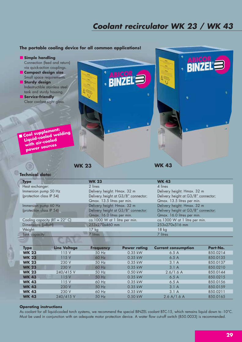
Coolant recirculator WK 23 / WK 43
Type Line Voltage Frequency Power rating Current consumption Part-No.WK 23 115 V 50 Hz 0.35 kW 6.5 A 850.0214WK 23 115 V 60 Hz 0.35 kW 6.5 A 850.0135WK 23 230 V 50 Hz 0.35 kW 3.1 A 850.0137WK 23 230 V 60 Hz 0.35 kW 3.1 A 850.0210WK 23 240/415 V 50 Hz 0.50 kW 2.6/1.6 A 850.0144WK 43 115 V 50 Hz 0.35 kW 6.5 A 850.0215WK 43 115 V 60 Hz 0.35 kW 6.5 A 850.0156WK 43 230 V 50 Hz 0.35 kW 3.1 A 850.0159WK 43 230 V 60 Hz 0.35 kW 3.1 A 850.0211WK 43 240/415 V 50 Hz 0.50 kW 2.6 A/1.6 A 850.0165
WK 23 WK 43
The portable cooling device for all common applications!
Simple handlingConnection (feed and return) via quick-action couplings.Compact design sizeSmall space requirements.Sturdy designIndestructible stainless steeltank and sturdy housing.Service-friendlyClear coolant sight glass.
Operating instructionsAs coolant for all liquid-cooled torch systems, we recommend the special BINZEL coolant BTC-15, which remains liquid down to -10°C.Must be used in conjunction with an adequate motor protection device. A water flow cut-off switch (850.0033) is recommended.
Technical data:
Type WK 23 WK 43Heat exchanger: 2 lines 4 linesImmersion pump 50 Hz Delivery height: Hmax. 32 m Delivery height: Hmax. 32 m(protection class IP 54) Delivery height at G3/8” connector: Delivery height at G3/8” connector:
Qmax. 13.5 litres per min. Qmax. 13.5 litres per min.Immersion pump 60 Hz Delivery height: Hmax. 32 m Delivery height: Hmax. 32 m(protection class IP 54) Delivery height at G3/8” connector: Delivery height at G3/8” connector:
Qmax. 16.0 litres per min. Qmax. 16.0 litres per min.Cooling capacity (RT = 22° C) ca.1000 W at 1 litre per min. ca.1300 W at 1 litre per min.Dimensions (LxBxH) 253x270x460 mm 253x270x516 mmWeight: 17 kg 18 kgTank capacity: 7 litres 7 litres
Cool supplement:
Liquid-cooled welding
with air-cooled
power sources

Notes

31
Notes

Alexander Binzel Schweisstechnik GmbH & Co. KGP.O. Box 10 01 53 · D - 35331 GießenPhone:++49 (0) 64 08 / 59 - 0 Fax: ++49 (0) 64 08 / 59 - 191Internet: www.binzel-abicor.com
W e l d i n g & c u t t i n g b r o u g h t t o t h e p o i n t .
Our product range:MIG/MAG• Welding Torches• Automatic and Special Torches• Push-Pull Welding Torches• Fume Extraction Torches• Central Adaptor System
TIG• Welding Torches• Automatic and Special Torches
PLASMA• Cutting Torches• Welding Torches• Automatic and Special Torches
Robotic Peripheral Equipment• Robot Torches
MIG/TIG/Plasma• Robot Mount CAT2• Torch Change System ATS-Rotor• Tool Change System WWS• Wire Cutting Station DAV• Torch Cleaning Station
BRS-LC and BRS-FP• Wire Feeding Station APD-MF
Welding Accessories• Cooling Device• Welding Cable Plug and Socket • Anti Spatter Spray and Paste
and so on …
PRO
.R12
1 •
Bi-2
.000
-08.
05-g
b •
Prin
ted
in G
erm
any
• ©
Cop
yrig
ht
M&
W