catchup edition 15 - bim
DESCRIPTION
SketchUcation Community NewsTRANSCRIPT
catchupsketchUcation community newsletter
NOVEMBER 201215th EDITION
www.sketchUcation.com
Make FurLearn how to use
Make Fur to bring your interiors to life
Hans WegnerComplete step by step
tutorial on modeling a Hans Wegner chair
Modo 601In depth Review with SketchUp
workflow
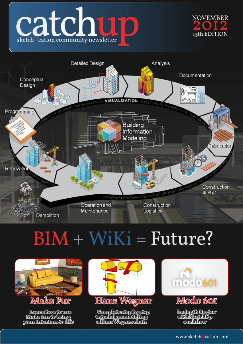
BIM + WiKi = Future?

www.sketchUcation.com 2
HaNs WEgNER04 Eric Lay returns with an epic tutorial in furniture modeling. Masterclass from Massimo siracusa.
CaRpET FUN21 Using MakeFur to simulate textiles. adriana granados walks you through generating rugs in seconds.
KEMp CasEsTUDy25 Duane Kemp’s incredible journey with Shaderlight. From still images to animations.
MODO MOjO22 The ins and outs of Modo 601. a look at Luxology’s latest release and why it is breaking new ground.
jOT TOUCH30 Pressure sensitivity pen. Mike Lucey takes adonit’s new pen for a testdrive.
WHaT Is BIM?28 Understanding BIM. Mike Lucey’s overview of BIM and sketch-Up going forward.
We have a bumper edition
month with some stellar uses
of sketchUp in store.
Eric Lay returns with what
can only be described as epic. a
true masterclass in modeling.
adriana granados show
us how to use Make Fur for
interiors and Duane Kemp
shares his experiences using
shaderlight.
Mayor Mike Lucey takes us
through the BIM process and
why it needs to evolve.
plus all the usual news,
reviews and sneak peeks.
Enjoy!
Chairs, fur, materials and
BIM

www.sketchUcation.com 3

Eric Lay
Hans Wegner CH07 Lounge Chair - 1963
To model any item it is helpful to have good
reference images. For this chair I have many
images showing different finishes and upholstery
options. I also have the side, top and front profile
with measurements which helps tremendously.
all of these were found easily online. This is
a beginner/intermediate sketchUp modeling
tutorial.
If you closely inspect this chair you will notice
that there are no compound curves to the wood.
This will make modeling the chair fairly simple.
you will need the joint push pull plugin
which can be found on sketchUcation and you
will also need the Tools on surface plugin.
www.sketchUcation.com 4
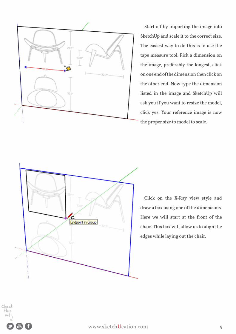
Start off by importing the image into
sketchUp and scale it to the correct size.
The easiest way to do this is to use the
tape measure tool. pick a dimension on
the image, preferably the longest, click
on one end of the dimension then click on
the other end. Now type the dimension
listed in the image and sketchUp will
ask you if you want to resize the model,
click yes. your reference image is now
the proper size to model to scale.
Click on the X-Ray view style and
draw a box using one of the dimensions.
Here we will start at the front of the
chair. This box will allow us to align the
edges while laying out the chair.
www.sketchUcation.com 5

Start off with an arc for the front of
the seat. For this model I am going to
make it a fairly high polygon model so
when you click the arc tool make sure to
type 48 in the VBC (Value Control Box)
before you draw the arc. Click on one
side of the box then perpendicular on
the other side. Finish the arc by drawing
the bulge. you can eyeball this part then
move the arc up or down to line it up the
way you want it.
Now make your box with the arc
into a component and name it “sEaT”.
Copy it to the right and rotate that
one 90 degrees and move it to the
front of the seat on the reference
image. Do the same with the top view,
rotating the component copy and
placing it at the front of the seat.
This will allow you to manipulate
your modeling on 3 axis giving you
better control over the desired shape.
www.sketchUcation.com 6
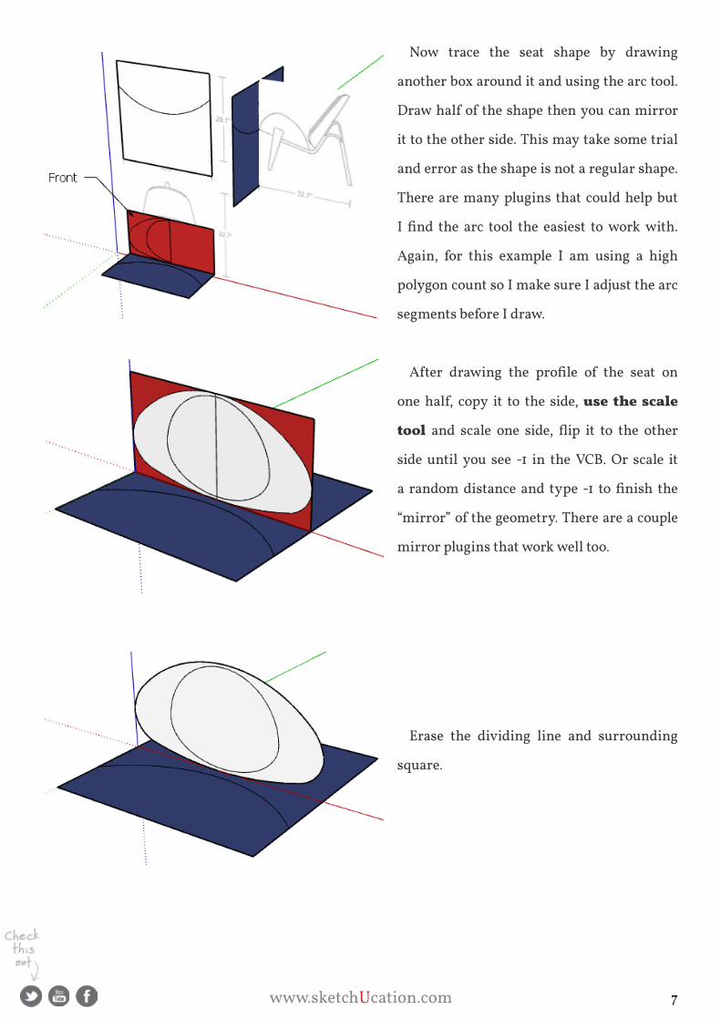
Now trace the seat shape by drawing
another box around it and using the arc tool.
Draw half of the shape then you can mirror
it to the other side. This may take some trial
and error as the shape is not a regular shape.
There are many plugins that could help but
I find the arc tool the easiest to work with.
again, for this example I am using a high
polygon count so I make sure I adjust the arc
segments before I draw.
After drawing the profile of the seat on
one half, copy it to the side, use the scale
tool and scale one side, flip it to the other
side until you see -1 in the VCB. Or scale it
a random distance and type -1 to finish the
“mirror” of the geometry. There are a couple
mirror plugins that work well too.
Erase the dividing line and surrounding
square.
www.sketchUcation.com 7
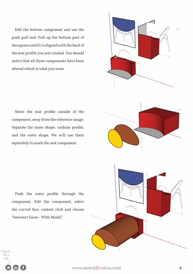
Edit the bottom component and use the
push pull tool. pull up the bottom part of
the square until it is aligned with the back of
the seat profile you just created. You should
notice that all three components have been
altered which is what you want.
Move the seat profile outside of the
component, away from the reference image.
Separate the inner shape, cushion profile,
and the outer shape. We will use them
separately to mark the seat component.
Push the outer profile through the
component. Edit the component, select
the curved face, context click and choose
“Intersect Faces - With Model”.
www.sketchUcation.com 8

Erase all the geometry except for the curved
seat shape. Close the component and erase the
shape you used to intersect with.
Now to make the seat thickness. The easiest
way to do this is to use the “joint push pull”
plugin. select the curved face, activate the joint
push pull tool and then click on the face. start
to pull the face away but before finishing the
thickness press the Tab key. This will bring up
a dialogue box.
For “Finishing options” choose “Keep original
faces”. Continue pulling the face out and type
¾” in the VCB. This will set the thickness.
Then press enter and the plugin will finish
the extrusion. You might have to manually fix
a face or two but most of the time this plugin
works fine without it. Use the eraser tool and
hold CTRL to smooth out the edge around the
seat.
www.sketchUcation.com 9

Now for the cushion. push the remaining
shape into the seat then edit the seat
component. select just the inner face of the
curve and intersect with model like you did
before. This will create the outline for the
cushion.
Erase the unwanted geometry and you
are left with just the seat and the cushion
outline.
Edit the seat component, select the
cushion face inside the seat and make it a
component called “seat Cushion”. Now edit
the seat cushion component, select the face
and activate the joint push pull plugin. start
to pull the face away but before finishing
the thickness press the Tab key. This will
bring up a dialogue box. For “Finishing
options” choose “Erase original faces”. This
will create a thickness and erase the face
you started with as well. Continue pulling
the face out and type 1/8” in the VCB. This
will set the thickness. Then press enter and
the plugin will finish the extrusion.
www.sketchUcation.com 10

Now select the face you just created and
press the scale tool. grab the center grip on
one of the sides and then hold control. This
will scale the face about the center of the
selection. Move it out 1.01 then do the same
thing for the top middle grip. scale it 1.01.
With the face still selected activate the
joint push pull plugin again. pull the face
out another 1/8” and leave it there.
Repeat this step again and then scale the
face about the center by .99 on the side and
top. you can see the cushion taking shape
now.
Do this a couple more times using joint
push pull and the scale tool until you have
the cushion shaped the way you want it.
www.sketchUcation.com 11

Now select all the geometry in the Seat Cushion component and soften all the edges. You can do this
in one easy step by turning on the Soften Edges palette under Window/Soften Edges. Move the slider
all the way to the right and check “Soften coplanar”.
Now close the bottom component and edit the one on the top right, the side profile. Select all the
geometry and rotate it from the front of the seat down. You might have to turn off the X-Ray view at
this point to better see what you are doing. Match the seat angle on the side profile. All three compo-
nents should have changed again. If you had just rotated the component without editing it, only one
would change. You are now finished modeling the seat and seat cushion. Let’s work on the back now.
www.sketchUcation.com 12

start the back the same way you did
the seat by using the reference image,
clicking on the X-Ray view style and
drawing a box. go ahead now and make it
a component called “seat Back”.
Now copy it a couple times and rotate
it appropriately aligned with the other
views just like you did with the seat. The
top left view won’t line up with the seat at
this point but that is fine, we will correct
that later.
Before you draw the profile for the seat
back, edit the seat back component and
rotate it into place. This is backwards
from the seat we did before but the angle
of the back is much greater so this way
will be more accurate. you may need to
enlarge the box
www.sketchUcation.com 13

Now draw the profile using parallel
projection on the reference image. you
might want to copy the reference image
off to the side for this as the seat and back
could be in your way trying to draw. This
may take some trial and error and a bit of
guess work at the bottom.
Edit the seat back component then use
the push/pull tool to give it the thickness
of the chair back. Use the reference image
in the upper right.
Move the profile for the chair back
down in line with the seat back compo-
nents. select all of the geometry in the
profile and cut the selection. Ctrl-X on the
pC. Then edit the seat back component
and paste the geometry into it. Ctrl-V.
Push/Pull the profile through the seat
back then intersect it with the front face.
To intersect it only with one face select
the profile you push/pulled and select
the face you want to intersect. Then
context click and choose Intersect Faces /
With selection. Otherwise if you do With
Model you will intersect everything that
face touches and in this case will create
extra geometry you don’t want.
www.sketchUcation.com 14
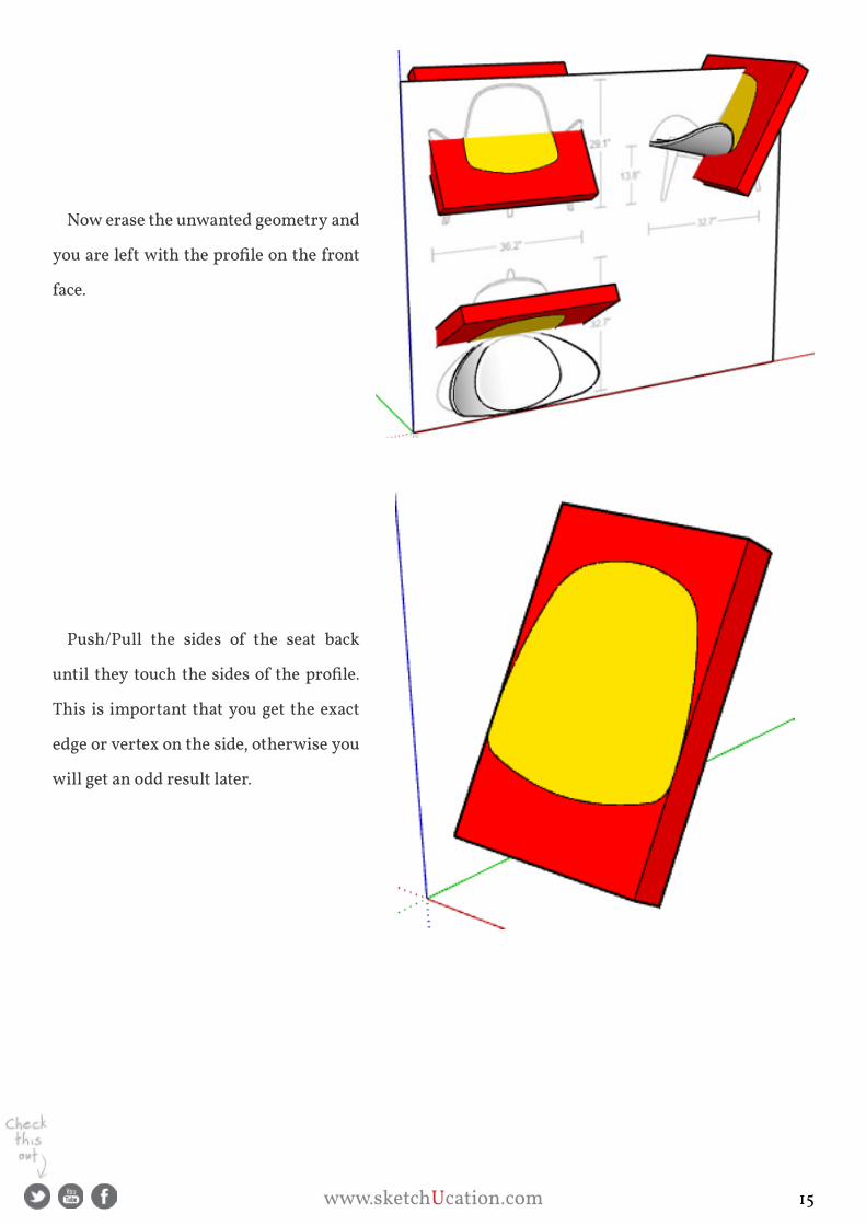
Now erase the unwanted geometry and
you are left with the profile on the front
face.
push/pull the sides of the seat back
until they touch the sides of the profile.
This is important that you get the exact
edge or vertex on the side, otherwise you
will get an odd result later.
www.sketchUcation.com 15

On the top of the box create an arc from
the corners and the bulge will be the
entire depth of the rectangle. Remember
we set the depth and width already so
this is an easy arc to line up.
Now push/pull the back arc to the
bottom of the box. Draw a reference line
“on axis” from the back face. Then
using the joint push pull plugin select
the profile face and click the Vector
push pull tool. This is critical as you
want the back profile to line up “on
axis”. Click one end of the reference
line then drag along it to finish the
vector push pull. Make sure it goes all the
way through the back.
www.sketchUcation.com 16
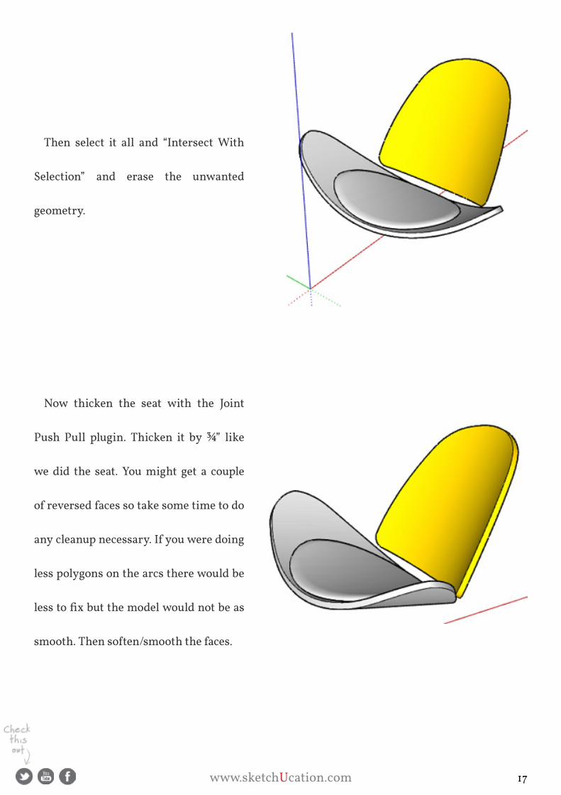
Then select it all and “Intersect With
selection” and erase the unwanted
geometry.
Now thicken the seat with the joint
push pull plugin. Thicken it by ¾” like
we did the seat. you might get a couple
of reversed faces so take some time to do
any cleanup necessary. If you were doing
less polygons on the arcs there would be
less to fix but the model would not be as
smooth. Then soften/smooth the faces.
www.sketchUcation.com 17

at this point if you look at the other
two sets of components, the top and front
they don’t line up with each other. go
ahead and delete them keeping only the
top right components. After we build the
cushion for the seat back we will copy
and align the front one to model the legs
properly.
For the seat back cushion your profile
will be inset the same shape as the seat
back. To do this on a curved surface use
the Tools On surface plugin. select the
seat back face and click “Draw Offset
Contours On surface”. Click the face
again and start pulling inward. Type ½”
into the VCB and press Enter.
www.sketchUcation.com 18

For the cushion now follow the same
steps as with the seat; make the face you
just offset a component, Joint Push Pull
out 1/8” then scale the surface. Repeat
until you have the shape you want then
smooth. again, with this many polygons
you might need to do a bit of cleaning up.
you can follow the remaining part of this tutorial on our Tutorial section where Eric show you
how to complete the legs. you can also purchase Eric’s Character Modeling Tutorial in our bookstore
which shows you the techniques used to create complex forms.
www.sketchUcation.com 19

www.sketchUcation.com 20

adriana granados
Make Fur = Make Fun
Make Fur by Tak2hata is a plugin
that many people use to provide
realism when creating grass or
vegetation. However it can also be
used as “hairy” textures such as
carpets and tapestries to achieve a
more realistic effect in a rendering.
In this scene I used Fur to
create the plant and the rug using
different parameters. These are
the parameters I used to create the
plant choosing the arch option to
simulate leaf fall.
“...achieve a more realistic effect in rendering....”
www.sketchUcation.com 21
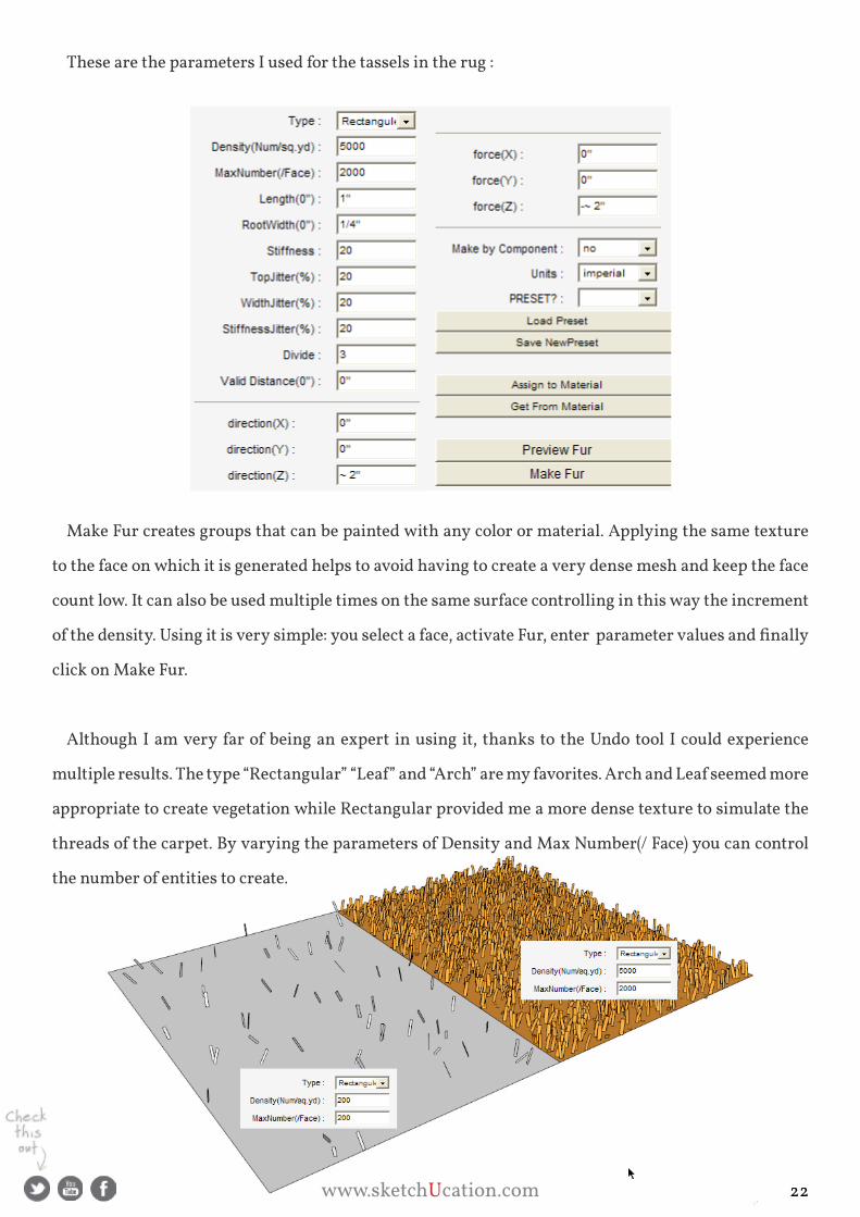
These are the parameters I used for the tassels in the rug :
Make Fur creates groups that can be painted with any color or material. applying the same texture
to the face on which it is generated helps to avoid having to create a very dense mesh and keep the face
count low. It can also be used multiple times on the same surface controlling in this way the increment
of the density. Using it is very simple: you select a face, activate Fur, enter parameter values and finally
click on Make Fur.
although I am very far of being an expert in using it, thanks to the Undo tool I could experience
multiple results. The type “Rectangular” “Leaf” and “Arch” are my favorites. Arch and Leaf seemed more
appropriate to create vegetation while Rectangular provided me a more dense texture to simulate the
threads of the carpet. By varying the parameters of Density and Max Number(/ Face) you can control
the number of entities to create.
www.sketchUcation.com 22

➙ Length and Rootwidth control the size of drawing entities. This is
great feature because you can create rugs and carpets with fibers of
different thickness. Rootwidth confused me at first because I thought
he meant the width at the root but then I realized it referred to the
dimension of the widest part. so for the case of plant leaves I enter a
greater value than for the case of carpet fibers.
➙ Stiffness is self explanatory although it was a trial and error process
which was more convenient to use.
➙ Top Jitter and Stiff Jitter randomize orientation and bending of the
entities
➙ Direction (X, y and Z) controls the overall orientation and Force (X,
y and Z) let you bend the entities as if the wind was blowing or in
the case of a tapestry on the wall could simulate gravity. you can also
pick a texture and the group will inherit the material.
Fur can also serve to create thatched roofs and have a margarita in the
shade!
adriana granados is an independent writer and author of sketchup
for Interior Design and space planning, the first books in Sketchup
dedicated to Interior Design. she has concentrated on the application
of information and communication technologies in the field of interior
design and architecture.
www.sketchUcation.com 23

www.sketchUcation.com 24

Mike Lucey
Kemp productions gets animated with shaderlight for sketchUp
Duane Kemp, director and owner of Kemp productions / kemppro.com, has been using sketchUp
since 2008. He’s been rendering for a couple of years and tried most renderers on the market, but was
never satisfied with the results. What Duane needed though was an affordable render plugin that could
deliver high quality images and render animations.
In 2011, Duane started rendering with shaderlight and was impressed with the image quality he
could achieve. Luckily the shaderLight team were in the midst of developing v2, which included an
animation feature so Duane helped them put the new release through its paces.
We spoke to Duane about his work using Shaderlight
He said: “Whatever the project, Kemp Productions has somehow found itself doing high poly, intricate or highly
detailed models both in complexity and size. We model and render high-resolution illustrations, animated logos, land-
scaped architectural builds, concept builds as well as 3D operation manuals.”
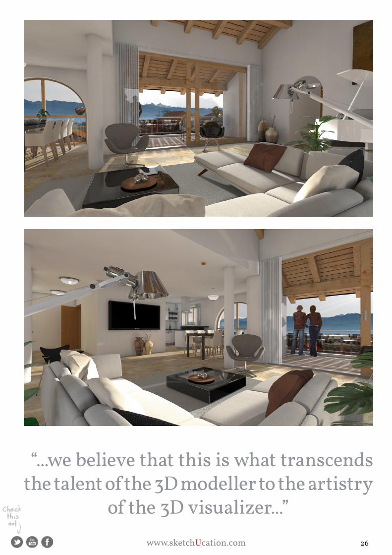
“We aim for photorealism in our work as we believe that this is what transcends the talent of the 3D modeller to
the artistry of the 3D visualizer. For our clients, the creation of visual reality is essential in conveying their vision suc-
cessfully.”
The Project
Kemp productions was asked to develop a series of promotional materials to publicise a new develop-
ment of luxury apartments. In addition to a logo, high resolution images and documentation, a new
iPad compatible website would feature two 30 second films - one showing the exterior of the building
within its village environment and the second, a virtual tour of the apartment revealing an amazing
view of Mont Blanc and the French alps.
www.sketchUcation.com 25
“...we believe that this is what transcends the talent of the 3D modeller to the artistry
of the 3D visualizer...”
www.sketchUcation.com 26
In order to achieve the desired result for the setting of this new apartment complex, Kemp produc-
tions set about modelling the actual buildings in the small town of Luins, switzerland, entirely in
sketchUp. The ‘Residence Michelange’ model had over 2,600,000 faces and took several months to
complete.
Duane said: “With the price-tag between 2 – 3’000’000 - CHF for each apartment , we wanted to communicate
the concept of “home” in the promotional imagery we produced so that potential buyers could imagine themselves
living there. The fact that all apartments sold in less than 4 1/2 months speaks volumes.”
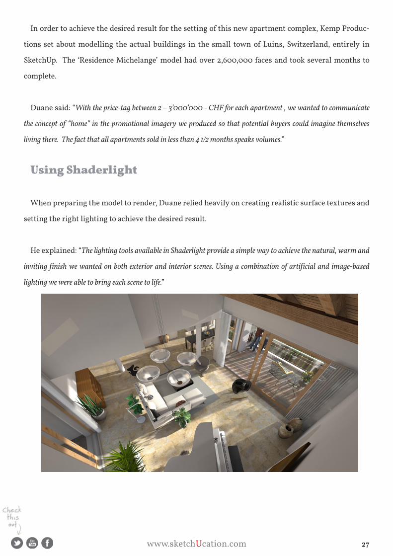
Using Shaderlight
When preparing the model to render, Duane relied heavily on creating realistic surface textures and
setting the right lighting to achieve the desired result.
He explained: “The lighting tools available in Shaderlight provide a simple way to achieve the natural, warm and
inviting finish we wanted on both exterior and interior scenes. Using a combination of artificial and image-based
lighting we were able to bring each scene to life.”
www.sketchUcation.com 27

With familiarity comes speed and, after using Shaderlight for a short time, Duane found he could
fine-tune each render setup with ease to produce the level of photorealism he wanted.
Duane said “Compared to some of the more complex renderers, Shaderlight makes rendering a scene in a real life
environment possible with little effort. From its simple toolset of user-friendly options that made rapid work of setting
surface reflectivity and bump mapping, to the clever feature that maintains render settings as you move through edits,
the software has a number of time saving features that proved indispensable for Kemp Productions”
He continued “I’m sure we could have got to the end of the project with other renderers but not, in our opinion, with
the same quality and ease of use as Shaderlight.”
The images rendered by Kemp productions for this project are available to view here.
Highlighting the quality Duane has managed to achieve with his shaderlight renders, one of the
images won third place in the shaderlight render contest held earlier this year.
Anatomy of a 3D Build using SketchUp
Kemp productions delivered a selection of 3D images, graphics and video content to its client - the
results of one year of modelling, collaboration with the architects and rendering animations for
Residence Michaelange.
To offer a step-by-step progressive tour that traverses the enormity of the job, Kemp Productions has
created the following video that dissects the project taking sketchUp users through ‘The anatomy of a
3D build.’
...more about shaderlight
Shaderlight is an interactive intuitive rendering plugin for SketchUp. To find out more and to
try it for yourself, visit www.shaderlight.com or If you’re looking to render animations or high
resolution stills and just don’t have the hardware, why not try shaderlight Cloud Rendering.
www.sketchUcation.com 28
www.sketchUcation.com 29
Mike Lucey
adonit jot Touch - pressure sensitivity
If you are lucky enough to use an ipad for
sketching I imagine you have wished your stylus
was a pressure sensitive device. With the recent
launch of the adonit jot Touch your wish could
come true. I recently tested the Touch and I am
very impressed with this device.
The packaging / instructions are excellent.
Even the instructions have artwork on the back
drawn with the Touch. There is also a replacement
nib and disk included. The new adonit Touch has
much the same quality feel as the original adonit
jot which I have been using for some time but a
lot has changed under the skin of the Touch.
The new Touch has a 10 hour
battery that needs to be charged
and this is achieved via a neat
magnetic UsB dongle. It is just
a matter of dropping the Touch
into the dongle and it begins
charging.
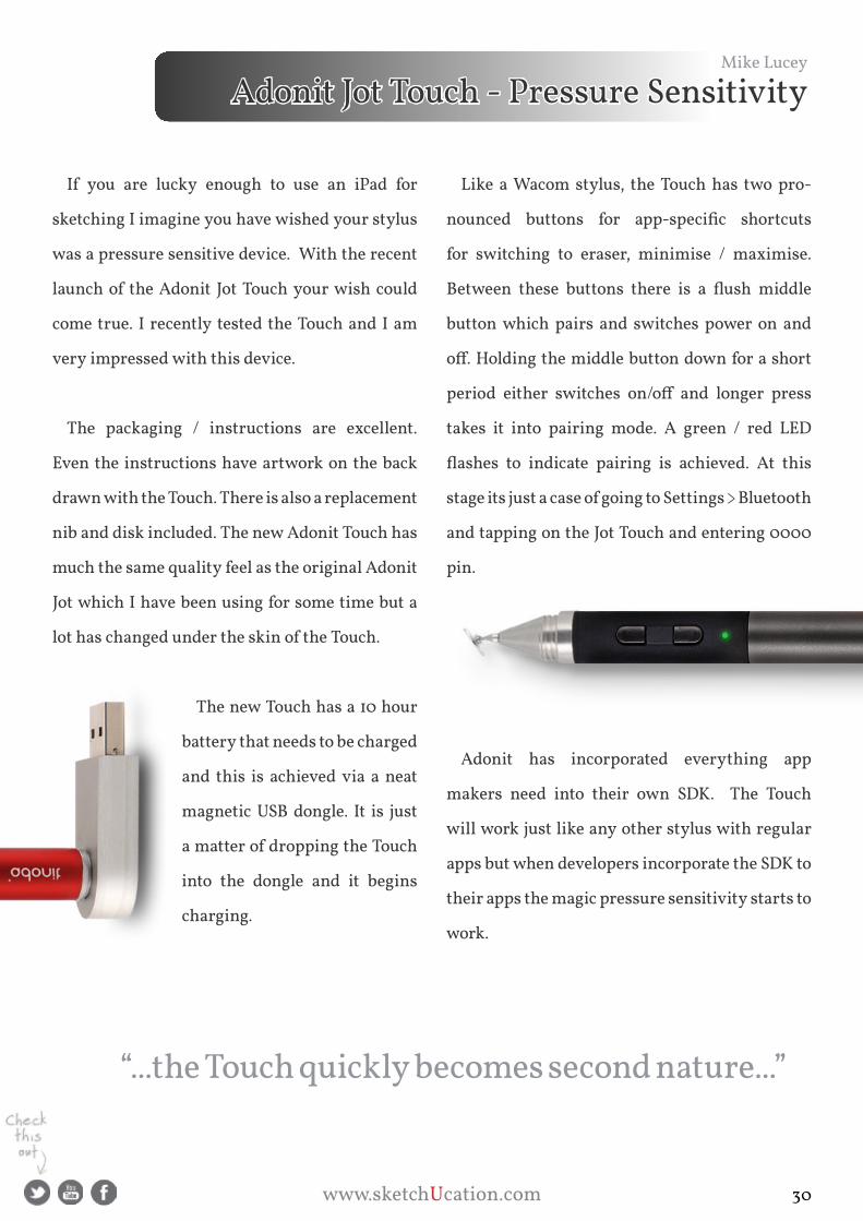
Like a Wacom stylus, the Touch has two pro-
nounced buttons for app-specific shortcuts
for switching to eraser, minimise / maximise.
Between these buttons there is a flush middle
button which pairs and switches power on and
off. Holding the middle button down for a short
period either switches on/off and longer press
takes it into pairing mode. a green / red LED
flashes to indicate pairing is achieved. At this
stage its just a case of going to settings > Bluetooth
and tapping on the jot Touch and entering 0000
pin.
adonit has incorporated everything app
makers need into their own sDK. The Touch
will work just like any other stylus with regular
apps but when developers incorporate the sDK to
their apps the magic pressure sensitivity starts to
work.
“...the Touch quickly becomes second nature...”
www.sketchUcation.com 30

Over Bluetooth, the Touch relays pressure information,
256 microscopic levels, to applications like procreate, sketch-
book, Clibe, pDF pen and others. The app translates this in-
formation into different sizes and opacities of ‘ink’ and ‘paint’
dispersal. The harder you press, the more that shows, going
from a thin feint line to a thick full brush stroke. I would add
that a little practice
is required to get the
expected results but the Touch quickly become second nature.
The Touch’s tip feels almost exactly like that of a real pen (with the exception of the small plastic disc)
due to the new sound dampening tip which simulates the natural contact (feel) of writing / drawing
with a pen on paper. The combination of the ipad 2 or New ipad with an adonit Touch will change the
way designers knock out their quick freehand sketches and in the case of artists, their creative art. at
$99 the Touch is a steal! Check it out.
www.sketchUcation.com 31

Late last month SketchUcation member MyHand dropped an excellent plugin, that tackles the often
laborious task of material replacement in sketchUp, called Material Maintenance. Using materials in
sketchUp can quickly become a dark art when you are dealing with components, groups and layers not
to mention the number of materials you may have in your model at any one time.
With Material Maintenance this is now completely streamlined under one very powerful tool. Below
you can see the dialog box that is displayed when you activate the tool.
There are 3 primary areas which allow for a huge amount of tweaking. The top zone, Material to
Replace, is where you can target your materials based on selection, model or component along with
highlighlight these materials using construction lines, selections or layers.
Rich O’Brien
Material Maintenance v2.1
www.sketchUcation.com 32

The really clever part of Colored Layer is that it will temporarily create a new layer called _FINDER_
and assign the object to that layer. This means in very complex models you can easily concentrate on
where you need to make changes. As soon as you toggle Color Layer off the object will return to its
original layer.
The centre zone, New Material, contains your applied materials and is used to swap materials out
based on what you select in the top zone.
The bottom zone, Apply To, is where you get to really fine tune your material replacements. Whether
you want to completely swap materials on every element or just target components you can tailor the
replacement vey precisely without having to dig through nested elements.
you can watch this video below to see an overview of what Material Maintenance is capable of.
www.sketchUcation.com 33

www.sketchUcation.com 34

Freebies & more....
There’s been a bit of surge in the forums of
late with members sharing top quality. Earlier
this month the maestro of Watercolours, allan
Casas, shared some excellent Ikea models
- Egon, Ellan and Balser
you can also purchase 33 Lo-poly chairs from
allan’s shop.
alvydas Litvinas shared some doors that will look
great in any rendered scene. you can also purchase
more of alvis’ incredible models in our Model shop
as well as his detailed pDF tutorials in our Book
shop.
Finally, if you haven’t grabbed Oli shea’s Curved
Tree Lines then you need these for your archViz
scenes. Oli also has some incredible HDRI packs
and even more high quality Tree Lines in our
Texture shop.
www.sketchUcation.com 35
www.sketchUcation.com 36

Online Tutorials
Learn how to remove .png halos from your sketchUp 2D exports
and make a sketchUp style that makes sure you never have to dig
through the option again!
Wield Thomthom’s Vertex Tools like a boss and learn to make
your own palm Trees.
part 1 - The Trunk part 2 - The Leaves
Learn how to make a spiralling stairs when you have no CaD
files only an image.
Tip and tricks when it comes to understanding the paint Bucket
tool and components.
Halo around transparent .png files
Model a palm tree with Vertex Tools
spiral staircase from 2D plans
In and outs of texturing in sketchUp
www.sketchUcation.com 37

www.sketchUcation.com 38

Rich O’Brien
Modo 601 - Review
When a user manual of over 1,800 pages is unfurled in front of
you it is a natural reaction to run for the hills. For nearly 2 months
I poured over every feature, function and doodad in Modo 601
and I am still returning to the manual on a daily basis. This is not
a failing in Modo it is an absolute neccessity if you really want to
raise your 3D game to the next level.
No amount of text can do justice to what lies under the hood in
Modo. It’s deep....very deep! In fact it requires an insane level of
dedication to learn every aspect. But it is a true next-gen 3D ap-
plication that brings modeling, texturing, rendering, animation,
dynamics and volumes all under one roof.
Imagine sketchUp, Thea, Cinema4D, Lumion and Blender
blended together and mixed with photoshop and you begin to see
why Modo is an exciting tool in any 3D pipeline.
www.sketchUcation.com 39

Modo’s UI is, at first, slightly intimidating. This is especially true if you have spent most of your time
cosied up with sketchUp. But this is akin to comparing apple to pears. Modo’s layout is tailored around
workflow. You are never 2 or 3 clicks from the tool you need.
Across the top are these 9 tabs that allow you to transition from different layouts and workflows with
a single click. So if you want to UV map after modeling it changes the workspace and toolset instantly.
you can then quickly transition to rendering and have all the necessary tools and layouts require for
that. It is massive timesaver in terms of workflow and output.
The actual primary tools rest on the right and these use the
same tabbed principle. Here is a typical modeling toolset with the
generic primitives available to begin with. But as you model and
need to perform more complex and involved manipulations you
click the required tab and a new set of tools are available.
This really unclutters the workspace and menu system and
provides a very visual means of portraying tasks via icons and
text.
Modo really is about looking, exploring and experimenting.
Compared with sketchUp’s very tactile approach to modeling
Modo takes a different path. Whilst you still perform the task in a
similar manner you are given a more varied approach to the end
result.
‘...you are never 2 or 3 clicks from the tool
you need...’
www.sketchUcation.com 40

On the right is Modo’s version of
Outliner. The top portion lists every
item in your scene and below you can
control each item’s properties.
This is the most involved aspect
with Modo because of the level of
control you are given. Cameras,
meshes, materials, environments,
lighting etc., are all tweaked here.
Whether you want to position a
camera, adjust a texture property or
control the falloff of an objects shadow
you manage all this here. This area
requires the most amount of dedica-
tion to really get to grips with.
The main point here is that you are
given an infinite amount of control of
every item in your scenes. If you have
a background in 3Ds Max or Blender
you will immediately identify with
this type of scene management.
some of the more involved aspects
are well documented in the user
manual and on the Luxology forums.
www.sketchUcation.com 41

Finally, there’s the workspace where the magic happens. you’ll immediately notice the ghosted grid
which is called the Work plane. This is probably must important part of Modo’s modeling approach
because drawing in 3D on a 2D screen is unnatural. Many applications resolve this using 4 viewports
for Front, Top, Side and Perspective. Modo’s Work Plane offers the same functions while allowing you
to remain in the 3D workspace and focused on one viewport.
In essence, it prevents the users placing geometry arbitarily off in the distance by always snapping to
the Worp plane. you can also set the Work plane to snap to edges, polygons or positions which makes
it a very flexible and versatile tool which makes the need for modeling with 4 viewports redundant.
Coupled with the Work plane is the action Centre which also plays a major roll in modeling. Ev-
erything in Modo is manipulated via gizmos - Moving, scaling and Rotating - and the action Centre
allows you to control how these Gizmos are affecting the geometry you manipulate. Need to position
the gizmo to align to a polygon’s centre, world axis, screen etc,. it is all available via the action Centre.
www.sketchUcation.com 42

so how does Modo play with sketchUp
models? Firstly, Modo doesn’t import .sKp
format so you need to export. I found .FBX
and .OBj exports from sketchUp imported in
Modo with not too many issues other than
texture maps and triangulation. Modo does
have a very clever mesh cleanup tool that
make light work of fixing things.
There are some plugins that allow direct
import of .sKp into Modo but I didn’t test
these. The main thing to consider here is that
to achieve the best result it is best to perform
all modeling in Modo. If you do need to have
some type of SketchUp/Modo workflow then
there are certain rules to adhere to that make
the process seamless.
➙ Make all faces in sketchUp quads (No
n-gons)
➙ Work with groups/components to
separate meshes
➙ Use sketchUp layers to create separate
meshes in Modo
➙ Export units in meters
By and large the you can quite easily
integrate both applications into your
workflow.
‘...versatile tool which makes the need for modeling with 4 viewports
redundant...’
www.sketchUcation.com 43
Where Modo begins to shine is when you hit
the hi-poly count. It has heaps of features that
make working on poly heavy scenes very fluid.
Whether you want to populate a scene with tens,
hundreds or even thousands of X-Frog trees or
create that perfect manicured lawn with grass
you can do this using Modo’s instancing and fur
tools.
There is also a Replicator Tool that allows you to
randomly array any amount of vegetation and
rocks in your scene using only a few “proxy”
objects. you can randomly scale and rotate each
object for a very natural scattered effect.
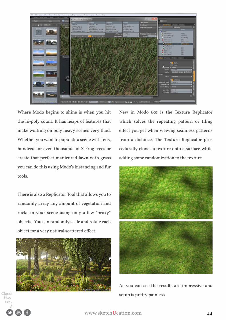
New in Modo 601 is the Texture Replicator
which solves the repeating pattern or tiling
effect you get when viewing seamless patterns
from a distance. The Texture Replicator pro-
cedurally clones a texture onto a surface while
adding some randomization to the texture.
as you can see the results are impressive and
setup is pretty painless.
www.sketchUcation.com 44
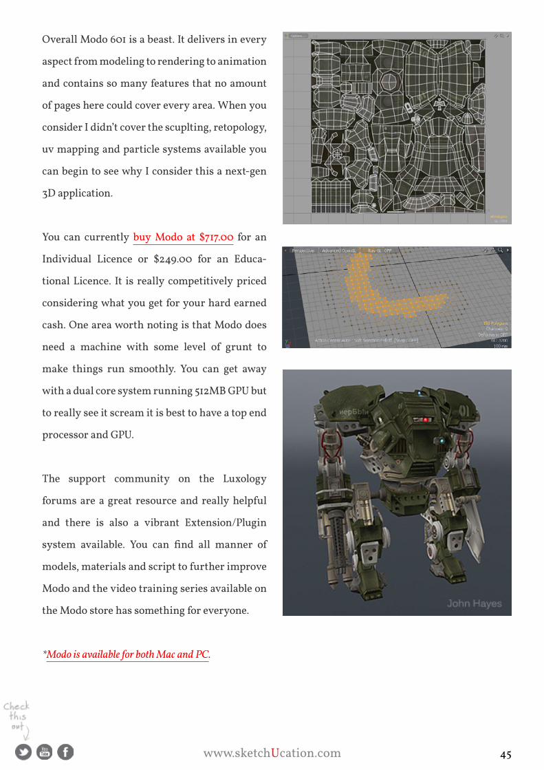
Overall Modo 601 is a beast. It delivers in every
aspect from modeling to rendering to animation
and contains so many features that no amount
of pages here could cover every area. When you
consider I didn’t cover the scuplting, retopology,
uv mapping and particle systems available you
can begin to see why I consider this a next-gen
3D application.
you can currently buy Modo at $717.00 for an
Individual Licence or $249.00 for an Educa-
tional Licence. It is really competitively priced
considering what you get for your hard earned
cash. One area worth noting is that Modo does
need a machine with some level of grunt to
make things run smoothly. you can get away
with a dual core system running 512MB gpU but
to really see it scream it is best to have a top end
processor and gpU.
The support community on the Luxology
forums are a great resource and really helpful
and there is also a vibrant Extension/plugin
system available. You can find all manner of
models, materials and script to further improve
Modo and the video training series available on
the Modo store has something for everyone.
*Modo is available for both Mac and PC.
www.sketchUcation.com 45

www.sketchUcation.com 46

Mike Lucey
What is BIM?
BIM or Building Information Manage-
ment is much talked about in the building
industry these days but what is it really?
Some say BIM is a type of software application
or a 3D model of a building while others comment
that BIM is a system process or that BIM is just
an organised collection of building data. BIM is
all of the above and more also new features are
being added continuously to the process as they
become practicable and useful in the building
and ongoing maintenance processes, the latter
sometimes not given the consideration it fully
deserves.
I have been taking a renewed interest in BIM
of recent and particularly so after Trimble’s ac-
quisition of sketchUp and its newly announced
‘Trimble Buildings’ platform with it’s (DBO)
‘Design - Build - Operate’ process. It is interesting
to note one of Trimble’s latest acquisitions, Vico
Software. This firm offers consulting services
and is also a developer of 5D virtual construc-
tion software. I like the way Vico can actually
work with the potential client/customer and
show how their systems work in the real world
at a practical hands-on level prior the potential
client/customer making a decision to purchase a
system.
‘3D modelling applications like sketchUp pro at the front end on a BIM platform may well be the way forward’
www.sketchUcation.com 47
On looking at other recent Trimble acquisi-
tions the Trimble Buildings platform is becoming
clearer and especially how SketchUp will fit into
the overall picture. To date sketchUp has made
3D modelling ‘easy’. Its could well be the case that
it will now play a major part in making the BIM
/ DBO platform / system easier for its adopters!
In order to better understand BIM and how
it helps in the design / build process and not to
forget required ongoing building maintenance
period, I will go through what I see as the main
components currently involved.
When it comes to the nuts and bolts of BIM,
things start to happen with the development of
the 3D building model. personally, I would like
to see it start more seriously at the rough sketch
stage. Maybe this is where sketchUp can come
into play more in the future.
However at the moment it appears to start with
the 3D model. The 3D model required for BIM has
to be more than just simple geometry and some
textures added to it for visualisation. An effective
working BIM model consists of the virtual
equivalents of the actual building components /
sections used to create a building. These intelli-
gent elements combine to form digital prototypes
of the physical building with elements such as
walls, columns, floors, windows and doors, stairs
etc that allow the simulation of the building and
understand its behaviour before the actual con-
struction begins.
I can imagine this process, over time, will
develop to a level where the occupants can gain a
full virtual experience of the building for periods
of time to determine if the building is a good ‘fit’
for their needs / requirements. The technology
is already there (and working well) to do this, it
just needs to be fine tuned and brought into the
BIM model / process. Maybe this will be a future
acquisition for Trimble!
“...intelligent elements combine
to form digital prototypes that
allow the simula-tion of a building and understand its behaviour”
www.sketchUcation.com 48

I can imagine this process, over time, will
develop to a level where the occupants can gain a
full virtual experience of the building for periods
of time to determine if the building is a good ‘fit’
for their needs / requirements. The technology
is already there (and working well) to do this, it
just needs to be fine tuned and brought into the
BIM model / process. Maybe this will be a future
acquisition for Trimble!
What can a BIM model be used for?
- 3D VIsUaLIZaTION
Of course one of the most basic uses for a (3D)
BIM model is creating realistic visualisations of
the planned building. The BIM model also helps
in design decisions by comparing various design
options / alternatives and at this stage it can be
leveraged to also sell the design proposal to the
client, local authorities / community and other
stakeholders.
- CHaNgE MaNagEMENT
since data is stored in a central place in a BIM
model, any modifications to the building design
can / will be automatically updated in each view
such as floor plans, sections and elevations.
This not only helps in creating the documenta-
tion faster but also provides stringent quality
assurance by automatic coordination of the
different views.
- BUILDINg sIMULaTION
BIM models contain more than just archi-
tectural data. Information about the various
engineering disciplines, sustainability informa-
tion and other characteristics / installations can
be easily simulated and virtually tested well
in advance of actual construction allowing for
further fine-tuning.
- DaTa MaNagEMENT
BIM also contains information that is not
visually represented in the 3D model. scheduling
information, for example, clarifies the necessary
manpower / skills coordination, materials, plant
and anything that might effect the outcome of the
project schedule particularly the ‘bottom line’!
Construction cost is most definitely and
important part of BIM, often the all important
part these days in my opinion. This allows the
designers to see what the budget or estimated
cost of the project might be at any given point in
time during the project with the exception of the
very preliminary rough sketches and creative
doodles!
www.sketchUcation.com 49

www.sketchUcation.com 50
Needless to say the data put into a BIM model is
not only useful during the design and construc-
tion phase of a building project but can be used
throughout the entire building lifecycle to help
reduce the operation and ongoing management
costs of the building which can and often is sig-
nificantly more than the entire cost of the initial
construction.
- THE BIM TEaM
a building project has many participants, ar-
chitects, engineers, consultants, constructors
etc. They all have different roles, goals, agendas
and priorities and firms often run a number of
projects in parallel. Combine this with the dif-
ferences between building standards and con-
ventions in different regions / areas that require
different solutions and we can see why single
platform strategy is not the solution to the aEC
collaboration.
a pre-BIM team collaboration scenario might
have worked along the following lines.
➙ The architect, engineer and constructor are working
on the same building project, lets say, a reasonable
sized multi-storey building.
➙ The architect prepares the design, a 3D model, and
needs to coordinate with the engineer for initial
structural element sizing etc and sends the data
(3D Model) to the engineer for assessment / struc-
tural details / proposals.
➙ More often than not, the architect’s drawings /
3D model is full of architectural details that can
be just noise to the engineer who needs only the
load bearing structures / details. In this case, the
engineer will often either clean up the architect’s
drawings / 3D model or reproduce the structural
elements from scratch. This is not efficient.
What is really needed here is a workflow com-
patibility to ensure that the other party, can if
required, only get elements relevant to their part
of the project, in other words, no noise, and get
them early on in the design process so they can
have relevant constructive input from as early on
in the off-set as possible.
www.sketchUcation.com 51

- DaTa INTERpRETaTION
Ideally the architect should only be sending
relevant data to the engineer. This being the case
the engineer will be able to start on the structural
analysis of the building and produce a logical
solution for the building structure, columns,
floors etc at an early stage that may well, for
example, facilitate the designer as there will be
less ‘head scratching’ when deciding on spans etc.
- MaNagINg CHaNgE
Once a proper BIM workflow is established and
exercised both the architect and engineer can
work better within their own areas of expertise
and at the same time feel confident that what
they are doing is known to the other party via an
accurate, up to date, BIM model.
Ideally, as they progress in the design and
eventual construction phase, which will involve
constructors, all will be in sync with the use of
the BIM model if this workflow compatibility is
maintained and communication is multi-direc-
tional, between all design professionals, allowing
any design changes to be handled in an intelli-
gent way and recorded in the BIM model.
Once the constructor comes into the picture
and the construction starts, it becomes more
obvious that the architect and engineer have been
working on their own particular models and only
used the other party’s model as a reference but
all the data is combined in the BIM model for all
involved, particularly the constructor.
- OWNERsHIp OF DaTa
Both the architect and structural engineer
manage and maintain their own models. The
reason is that workflow compatibility requires
that the real-world setup be mirrored so parties
carry full responsibility for their part of the
project, they may well also require mutual
ownership of all BIM data. It’s not file compat-
ibility but rather workflow compatibility that can
make or break open collaboration between the
various stakeholders of the aEC industry. With
open collaboration all participants of the aEC
workflow enjoy unique benefits.
- UNIQUE BENEFITs
project members can choose to work with the
best of breed solutions in their respective fields
and locations.
project members can decide about their
software upgrades independently from their
peers in different projects.
project coordination errors are greatly reduced
due to workflow level compatibility in contrast to
just file compatibility alone, the old system!
www.sketchUcation.com 52

accessibility of BIM data is provided through-
out the entire life cycle of the building, including
construction and ongoing operation thus
reducing maintenance costs.
Before concluding I should mention that there
is a school of thought that also feels current BIM
offerings are not yet the ideal answer by them-
selves or at least not without a good communi-
cation system as it does not always contain and
make more efficient all the communication that
takes place within and across the design teams.
The problem can be ‘noise’ in communications!
as building processes become more complex
with larger design / build teams there is more
reliance on email, fax, audio conferencing and
web conferencing. Many are expressing views
that there can often be a lot of communication
confusion resulting in delays and in turn cost
increases.
www.sketchUcation.com 53

a possible solution being put forward to solve
this problem is the use of WiKi platforms. It
seems the fundamental concept of WiKi and BIM
are quite similar. Both enable multiple individu-
als to access and modify the data and information
stored at a single location. I think there is most
definitely a place for a WiKi type communication
system within the overall BIM model. some of
the advantages of this particular platform are -
➙ Wikis can be used to replace much non confidential
email communication and create long term infor-
mation value and have same available generally
to the overall team.
➙ Wikis can be used to retrieve information that
may have been lost when a member of the team is
no longer with the company. Past projects can be
archived and made retrevable.
➙ Different discipline team members can have input
via designated areas and freely make suggestions
that could well be of value. Sometimes great ideas
come from team members that are not directly
involved in the particular process.
➙ Wikis can often reduce meeting times and
sometimes eliminate the requirement for meetings
as issues get resolved by the design team’s involve-
ment / effort. In other words the issue can well be
resolved before it becomes a problem.
Dare I say that sketchUcation could be looked
on as an example of how a Wiki has been utilised
in the area of sketchUp plugin development over
the past 6 years and is still continuing to deliver
positive results in this area.
Using current BIM as it is, and future versions
effectively, may well improve constructibil-
ity, shorten build time and positively impact the
often all important ‘bottom line’ in the initial
stages and ongoing stages of the building. I feel
with the integration of quick and simple to use
3D modelling applications like sketchUp pro at
the front end on a BIM platform may well be the
way forward.
‘...fundamental concept of WiKi
and BIM are quite similar...’
www.sketchUcation.com 54

www.sketchUcation.com 55

www.sketchUcation.com 56
EA
RTH
WO
RK
FRA
MIN
G
ADMIN
BIM
TE
CH
DE
SIG
N
2D D
OC
S
BID
DIN
G
CO
NTR
AC
T
STA
GIN
G
SITE
PR
EP
STR
UC
TUR
E
SHE
LL
SYS
TEM
S
FIN
ISH
ES
FIN
AL
CONSTRUCTION PROCESS
LIFE CYCLE
BIM
EA
RTH
WO
RK
FRA
MIN
G
ADMIN
BIM
TE
CH
DE
SIG
N
2D D
OC
S
BID
DIN
G
CO
NTR
AC
T
STA
GIN
G
SITE
PR
EP
STR
UC
TUR
E
SHE
LL
SYS
TEM
S
FIN
ISH
ES
FIN
AL
CONSTRUCTION PROCESS
LIFE CYCLE
BIM
It’s hard to believe but the first commercially available email programs didn’t appear until the late 1980’s, and though the communication benefits of electronic messaging was clear by the mid 90’s, most construction companies didn’t use email until the very late 90’s and early 2000’s. It took a new generation of project managers to introduce this technol-ogy to reluctant companies – and as most would admit, the fight goes on.
Though cell phones and voice mail have obviously become critical for voice communications in construction, some offices continue to take messages and handwrite phone messages on old fashion pink tablets. Senior managers without keyboard skills have assistants handle emails, finding computers intru-sive and distracting. At the same time, according to The Mortensen Company, more contractors now use BIM than designers. Of course, it goes without saying that the average builder has no idea who Mortensen is, and though most construction managers may claim to own some version of BIM software, complex 3D modeling is largely ignored for spreadsheets and face to face fieldwork during construction. Even at Mortensen’s.
It’s no secret in a job trailer that BIM software requires trained technical skills, as well as constantly updated software and oversized workstations. In practice, working with this technology is simply not practical on a jobsite, especially when printed 2d contract documents are the basis for the actual scope of the work. It’s also important to point out that design, including BIM and tweaking it to generate 2D documents, is only a very small part of the real world construction process. Consider the computational tasks found in the timeline of a typical project.
The dark secret is that very few companies actually use the software for day to day project management
Memos, minutes, mes-sages, specs
Resources, maps/routes, bookmarks, weather
Daily and phase reports, CO, bulletins, and RFIs
Construction Modeling – Social Media Part 1
Rendered model re-view and approval
DESIGN
Analytical construction model in SketchUp
DESKTOP
Storage, FTP transfers, online resources and libraries
Data point conversions from SketchUp
EXPORT
Technical production documents
2d exports from the 3d BIM models
2d DOCS
Data exported from the BIM model
REPORTS
Construction documents printed for use on the jobsite
2d PRINTS INTERNET
Images and animations from the construction model
3d IMAGES
Immediate progress pho-tos, details, and scans
PHOTOS
2d and 3d images as con-struction documents
FIELD DOCS
REPORTS
Geo-located phase and detail SketchUp Scenes
Annotated graphic database exported from SketchUp
LIBRARY Preconstruction sequence animations from SketchUp
PROCESS MODEL
Voice, IM, texting, face to face, images
MESSAGING
Techs or Managers
Model World in the Real World
According to a recent tweet by the Mortensen Company, 74% of contractors now use BIM. Which is no surprise, given BIM is mandatory for contractors and subcontractors working on public projects
74% BIM

www.sketchUcation.com 57
Based on the value and cost of services, only 10% of the entire construction process is design, permitting, and pre-construction, and of that, perhaps half of design is BIM production. Following the money, the real focus should be on what is happening on the jobsite and the real world that surrounds it. Today, computer programs link to the web, send email from menu selection, and automatically upload to cloud stor-age. Communications between team members now occur on PDAs (personal data assistants) or smart phones that text and tweet with annotated high resolution photos and video. The mobility of computers has become a fundamental part of project communications. All of which is available wire-lessly via satellite, cells, or broadband routers, giving project managers immediate access to web resources, project bookmarks, searches, and marketing and networking platforms like Facebook, You-Tube, and Linked In.
Given the power of these devices, what’s interesting is how difficult it is to integrate these technologies into the actual construction process. A recent analysis by Pritesh Patel of Pauley Creative of a 2009 Construction Index survey found the top 15 of the 100 highest rated construction companies have yet to adapt to the communications potential of these new collaborative devices.
Important is that global resources and detailed project specific information can now be accessed, reviewed, and trans-ferred on ordinary laptops, touch tablets, pocket PDAs, survey instruments, and heavy machines and equipment. It’s also possible to capture images, download files, and communicate with team members using all of this information while on a jobsite, in an office, or anywhere else in the world.
A good example of one of the most promising new tools for construction communications is Twitter. This short-form messaging tool and micro-blogger is popular as a personal ad-vertising media, but it also has real potential as a “real time network” for ongoing conversation between team members. Next month we’ll start looking at Twitter as a management tool, organizing a team of fol-lowers with lists and groups, short form 140 character texts, transferring images, and how to pump up management tweets with apps like Tweet-deck, Seesmic, Tweetree, and Twubs.
According to a recent presentation by the Construc-tion Marketing Association, not only is social media underused, the po-tential of these new technologies for construction com-munications is not even recognized.
7 out of 15 top construction companies are on Twit-ter, but only 3 out of the 7 on Twitter are actually Tweeting. However, none of the top 15 construction companies are engaging with followers.
12 out of 15 top construction companies have a Linke-dIn company page, but only 6 out of the 12 have set up groups, and none are used for project communication.
14 out of 15 top construction companies have a pres-ence on Facebook, but only 3 out of the 14 have more than 10 fans or Likes. 2 out of 15 companies have placed links on their company websites to a social media profile.
1 out of the top construction 15 companies has no pres-ence on Twitter, LinkedIn or Facebook (not that Patel could find anyway).
INFO
GRA
PHIC
S/M
edia
Bist
ro.c
omExport from SketchUp
90% of Construction is Communications
A World of Information
Twitter (Next Month)

www.sketchUcation.com 58

RoundUp
Last Month we attended Basecamp 2012 in Boulder,
Colorado and were given a very warm welcome by
all the sketchUp team. From the party on the sunday
night through to the final day of activities it was a well
managed event.
It was wholly different from past events with the
focus heavily on transitioning to Trimble and building
the team with more developers. There were some
subtle hints at the direction sketchUp will take in the
coming years and genuine sense of excitement.
Not to mention the hat........ ;)
www.sketchUcation.com 59
