cathode fe board
DESCRIPTION
Cathode FE Board. The Ohio State University University of California Davis University of California Los Angeles CERN. Cathode FE Board. Mature Board - Only Small changes over last 3 Years!. MUX. 96 Channels. CMS CLK. Slow control. 7 in. BUCKEYE (ASIC) - amplifies and - PowerPoint PPT PresentationTRANSCRIPT
US
Cathode FE Board
The Ohio State University
University of California Davis
University of California Los Angeles
CERN
L.S. Durkin,ESR 9/00 2
Cathode FE Board
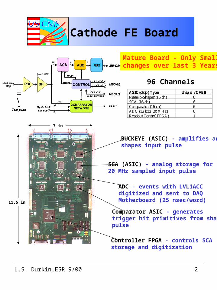
96 ChannelsASIC(chip) Type chip's / CFEBPreamp-Shaper (16 ch) 6SCA (16 ch) 6Comparator (16 ch) 6ADC (12 bits, 20 MHz) 6Readout Control FPGA) 1
7 in
11.5 in
BUCKEYE (ASIC) - amplifies andshapes input pulse
SCA (ASIC) - analog storage for 20 MHz sampled input pulse
ADC - events with LVL1ACCdigitized and sent to DAQ Motherboard (25 nsec/word)
Controller FPGA - controls SCA storage and digitization
Comparator ASIC - generatestrigger hit primitives from shapedpulse
Mature Board - Only Small changes over last 3 Years!MUX
CMS CLKCMS CLK
Slow controlSlow control
L.S. Durkin,ESR 9/00 3
Cathode FE Board
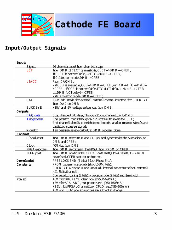
InputsSignal 96 channels input from chamber stripsLCT from DMB, if CLCT is available, CLCT-->DMB-->CFEB,
if CLCT is not available, -->FTC-->DMB-->CFEB,if Calibration mode, DMB-->CFEB
L1ACC From DAQMB,- if CCB is available, CCB-->DMB-->CFEB, or CCB-->FTC-->DMB-->CFEB - if CCB is not available, FTC (LCT delay)-->DMB-->CFEB,or, DMB (LCTdelay)-->CFEB,- if Calibration mode, DMB-->CFEB;
DAC 0-5V adjustable for external, internal charge injection for BUCKEYEfrom DAC on DMB
BUCKEYE +10V and -5V voltage references from DMBOutputs
DAQ data Strip charge ADC data, Through 21-bit channel link to DMBTrigger data Comparator Triads through two 28-bit multiplexers to CLCT;
End channel signals to neighboring boards, analog preamp signals anddigital comparator signals
Monitor Temperature sensor output, to DMB, program doneControls
Global-reset from DMB, reset DMB and CFEBs, and synchronize the 50ns clock onDMB and CFEBs
Clock 40MHz, from DMBFPGA-program from DMB, re-program the FPGA from PROM on CFEBJTAG port from DMB, controls: BUCKEYE data shift, FPGA resets, ISP-PROM
download, CFEB status monitor, etc.DownloadedConstants
PREBLOCKEND (4 bits) Block Phase ShiftPROM programming data (about 500K bits);BUCKEYE working mode (normal, internal capacitor select, external,kill, 3bits/channel);Comparator timing (3 bits), working mode (2 bits) and threshold
Power +6V: for BUCKEYE clean power (550-600mA)+5V: for SCA, ADC, comparator, etc. (900-1000mA)+3.3V: for FPGA, Channel link, CPLD, etc.(450-500mA)+5V and +3.3V power supplies are subject to change.
Input/Output Signals
L.S. Durkin,ESR 9/00 4
BUCKEYE ASIC
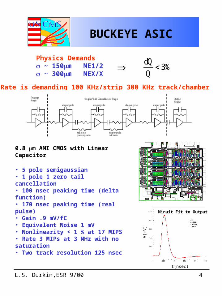
Physics Demands ~ 150m ME1/2 ~ 300m MEX/X
%3Q
Qd
0.8 m AMI CMOS with Linear Capacitor
• 5 pole semigaussian• 1 pole 1 zero tail cancellation• 100 nsec peaking time (delta function)• 170 nsec peaking time (real pulse)• Gain .9 mV/fC• Equivalent Noise 1 mV• Nonlinearity < 1 % at 17 MIPS• Rate 3 MIPs at 3 MHz with no saturation• Two track resolution 125 nsec
Rate is demanding 100 KHz/strip 300 KHz track/chamber
t(nsec)
V(m
V)
Minuit Fit to Output
L.S. Durkin,ESR 9/00 5
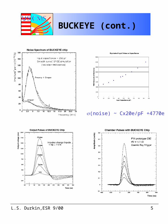
BUCKEYE (cont.)
(noise) ~ Cx20e/pF +4770e
L.S. Durkin,ESR 9/00 6
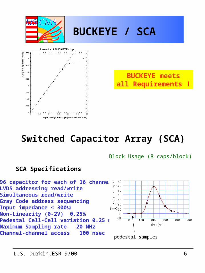
BUCKEYE / SCA
BUCKEYE meetsall Requirements !
Switched Capacitor Array (SCA)
SCA Specifications
- 96 capacitor for each of 16 channels- LVDS addressing read/write- Simultaneous read/write- Gray Code address sequencing- Input impedance < 300- Non-Linearity (0-2V) 0.25%- Pedestal Cell-Cell variation 0.25 mV- Maximum Sampling rate 20 MHz- Channel-channel access 100 nsec
Block Usage (8 caps/block)
pedestal samples
L.S. Durkin,ESR 9/00 7
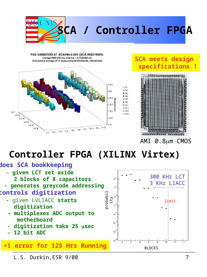
SCA meets design specifications !
SCA / Controller FPGA
limit
300 KHz LCT3 KHz L1ACC
BLOCKS
prob
abil i
ty
Controller FPGA (XILINX Virtex)- does SCA bookkeeping - given LCT set aside 2 blocks of 8 capacitors - generates greycode addressing- controls digitization - given LVL1ACC starts digitization - multiplexes ADC output to motherboard - digitization take 25 sec - 12 bit ADC
<1 error for 125 Hrs Running
AMI 0.8m CMOS
L.S. Durkin,ESR 9/00 8
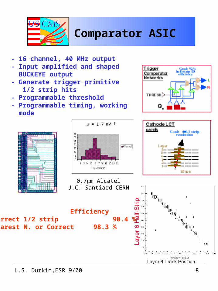
Comparator ASIC
- 16 channel, 40 MHz output- Input amplified and shaped BUCKEYE output- Generate trigger primitive 1/2 strip hits- Programmable threshold- Programmable timing, working mode
0.7m AlcatelJ.C. Santiard CERN
EfficiencyCorrect 1/2 strip 90.4 %Nearest N. or Correct 98.3 %
= 1.7 mV
L.S. Durkin,ESR 9/00 9
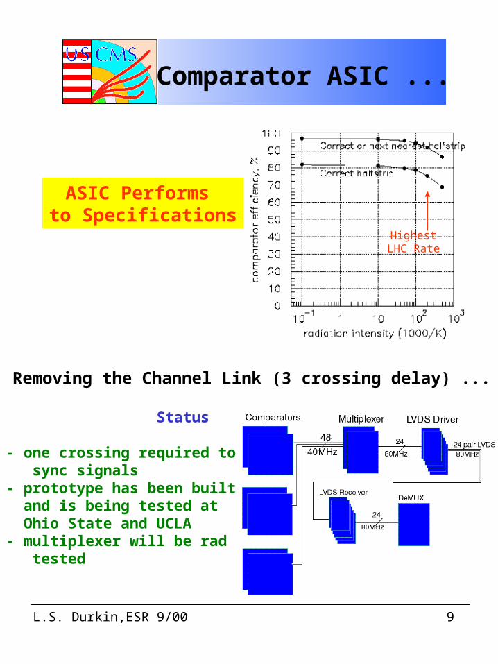
Comparator ASIC ...
ASIC Performs to Specifications
HighestLHC Rate
Removing the Channel Link (3 crossing delay) ...
Status
- one crossing required to sync signals- prototype has been built and is being tested at Ohio State and UCLA- multiplexer will be rad tested
L.S. Durkin,ESR 9/00 10
Calibration
0 - 5V 10 pF
10 pF
16-ch ASIC
strip
strip
16-ch ASIC
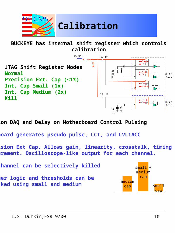
BUCKEYE has internal shift register which controls calibration
JTAG Shift Register ModesNormalPrecision Ext. Cap (<1%) Int. Cap Small (1x)Int. Cap Medium (2x)Kill
Precision DAQ and Delay on Motherboard Control Pulsing
- CCB board generates pseudo pulse, LCT, and LVL1ACC
- Precision Ext Cap. Allows gain, linearity, crosstalk, timing measurement. Oscilloscope-like output for each channel.
- Any channel can be selectively killed
- Trigger logic and thresholds can be checked using small and medium cap
smallcap
mediumcap
small +medium
cap
L.S. Durkin,ESR 9/00 11
Calibration ...
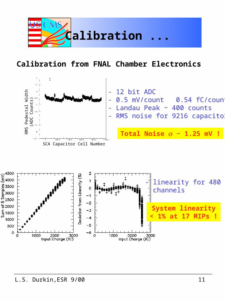
Calibration from FNAL Chamber Electronics
SCA Capacitor Cell Number
RM
S Pe
dest
al W
idth
(AD
C C
ount
s)
- 12 bit ADC- 0.5 mV/count 0.54 fC/count- Landau Peak ~ 400 counts- RMS noise for 9216 capacitors
Total Noise ~ 1.25 mV !
- linearity for 480 channels
System linearity< 1% at 17 MIPs !
L.S. Durkin,ESR 9/00 12
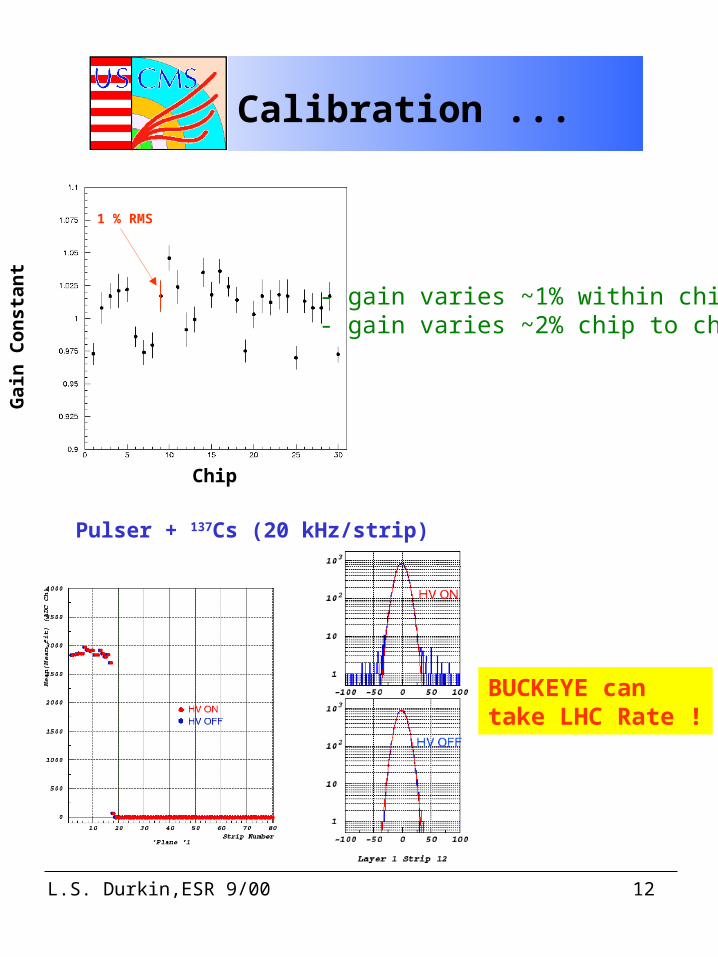
Calibration ...
1 % RMS
Chip
Gai
n C
on
sta
nt
- gain varies ~1% within chip- gain varies ~2% chip to chip
Pulser + 137Cs (20 kHz/strip)
BUCKEYE cantake LHC Rate !
L.S. Durkin,ESR 9/00 13
Timing / Slow Control
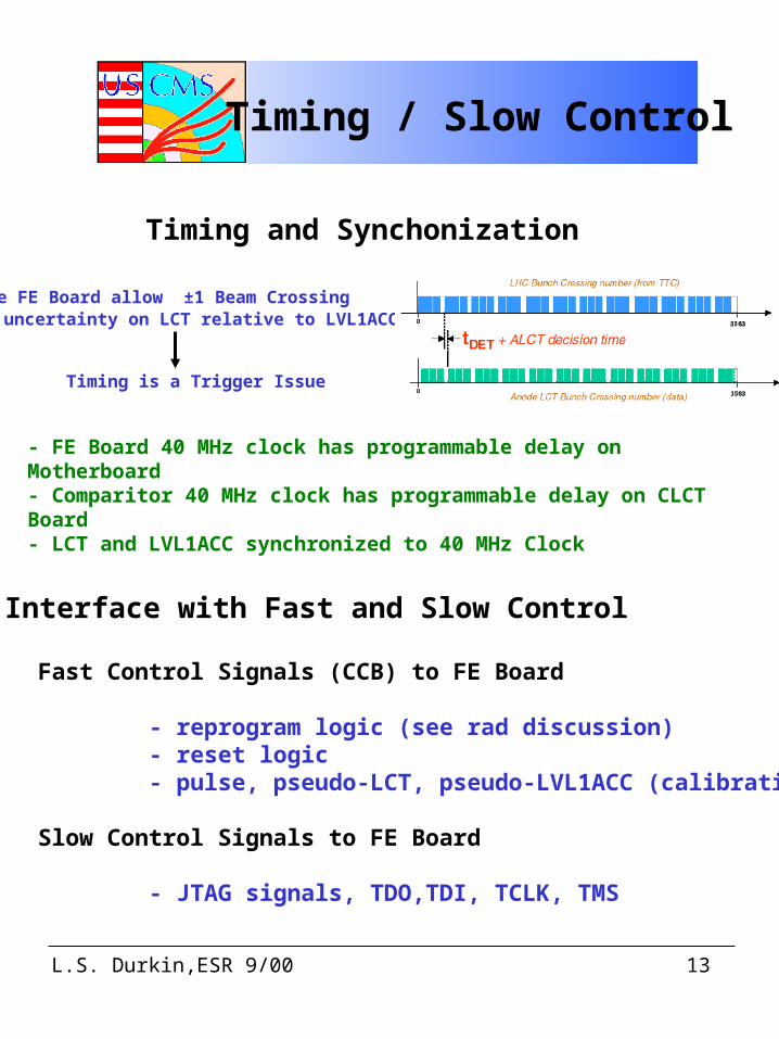
Timing and Synchonization
Cathode FE Board allow ±1 Beam Crossing uncertainty on LCT relative to LVL1ACC
Timing is a Trigger Issue
- FE Board 40 MHz clock has programmable delay on Motherboard- Comparitor 40 MHz clock has programmable delay on CLCT Board- LCT and LVL1ACC synchronized to 40 MHz Clock
Interface with Fast and Slow Control
Fast Control Signals (CCB) to FE Board
- reprogram logic (see rad discussion) - reset logic - pulse, pseudo-LCT, pseudo-LVL1ACC (calibration)
Slow Control Signals to FE Board
- JTAG signals, TDO,TDI, TCLK, TMS
L.S. Durkin,ESR 9/00 14
Slow Control
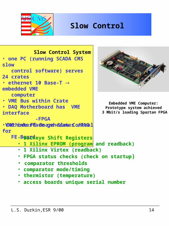
Slow Control System • one PC (running SCADA CMS slow control software) serves 24 crates• ethernet 10 Base-T embedded VME computer• VME Bus within Crate• DAQ Motherboard has VME interface -FPGA•VME interface generates JTAG for FE Board
Embedded VME Computer:Prototype system achieved
3 Mbit/s loading Spartan FPGA
Cathode FE Board Slow Control
• Buckeye Shift Registers• 1 Xilinx EPROM (program and readback)• 1 Xilinx Virtex (readback)• FPGA status checks (check on startup)• comparator thresholds• comparator mode/timing• thermistor (temperature)• access boards unique serial number
L.S. Durkin,ESR 9/00 15
Monitoring
Each FE Board has a 4 bit Beam Crossing counter - stored in data transferred to Motherboard
Each Digitized event has 8 checksum words (CRC15) - stored in data transferred to Motherboard - sensitive to channel link problems
LCT-LVL1ACC Coincidence Calculated both on FE Board and Motherboard Separately - motherboard knows when FE data not present - lack of data reported to DAQ
FE Boards send fixed data length records to FIFO on Motherboard - motherboard knows when data is missing - lack of data reported to DAQ - CFEB-Motherboard transmission timeout (10 sec)
Most failures will be detected before Periodic Radiation reload and resets allowing CCB to Reset the system !
L.S. Durkin,ESR 9/00 16
Radiation Tests
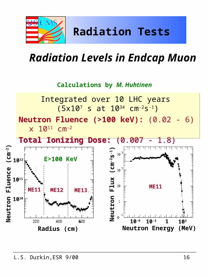
Radiation Levels in Endcap Muon Radiation Levels in Endcap Muon
Integrated over 10 LHC years (5x10⁷ s at 1034 cm-2s-1)
Neutron Fluence (>100 keV): (0.02 - 6) x 1011 cm-2
Total Ionizing Dose: (0.007 - 1.8) kRad
Integrated over 10 LHC years (5x10⁷ s at 1034 cm-2s-1)
Neutron Fluence (>100 keV): (0.02 - 6) x 1011 cm-2
Total Ionizing Dose: (0.007 - 1.8) kRad
Calculations by M. Huhtinen
Neutron Energy (MeV)1 10310-310-6
Neu
tro
n F
lux
(cm
-2s-1
)
Neu
tro
n F
luen
ce (
c m-2)
Radius (cm)
1010
1011
1012
ME11 ME12 ME13
E>100 KeV
ME11
L.S. Durkin,ESR 9/00 17
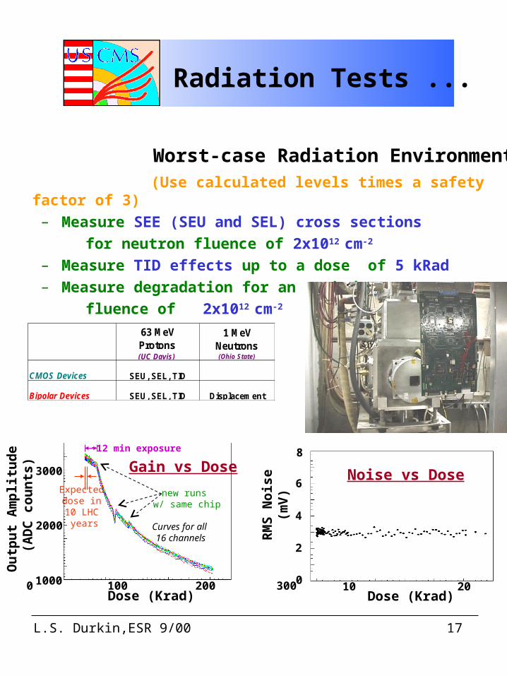
63 MeV Protons (UC Davis)
1 MeV Neutrons (Ohio State)
CMOS Devices SEU, SEL, TID
Bipolar Devices SEU, SEL, TID Displacement
Worst-case Radiation Environment (Use calculated levels times a safety factor of 3)
– Measure SEE (SEU and SEL) cross sections
for neutron fluence of 2x1012 cm-2
– Measure TID effects up to a dose of 5 kRad– Measure degradation for an equivalent neutron
fluence of 2x1012 cm-2
Radiation Tests ...
0
2
4
6
8
0 10 20 30Dose (Krad)
RM
S N
ois
e (m
V)
Noise vs Dose
1000
2000
3000
Dose (Krad)
Ou
tpu
t A
mp
litu
de
(AD
C c
ou
nts
)
Expected dose in 10 LHC
years
~12 min exposure
new runs w/ same chip
Curves for all 16 channels
Gain vs Dose
0 100 200 300
L.S. Durkin,ESR 9/00 18
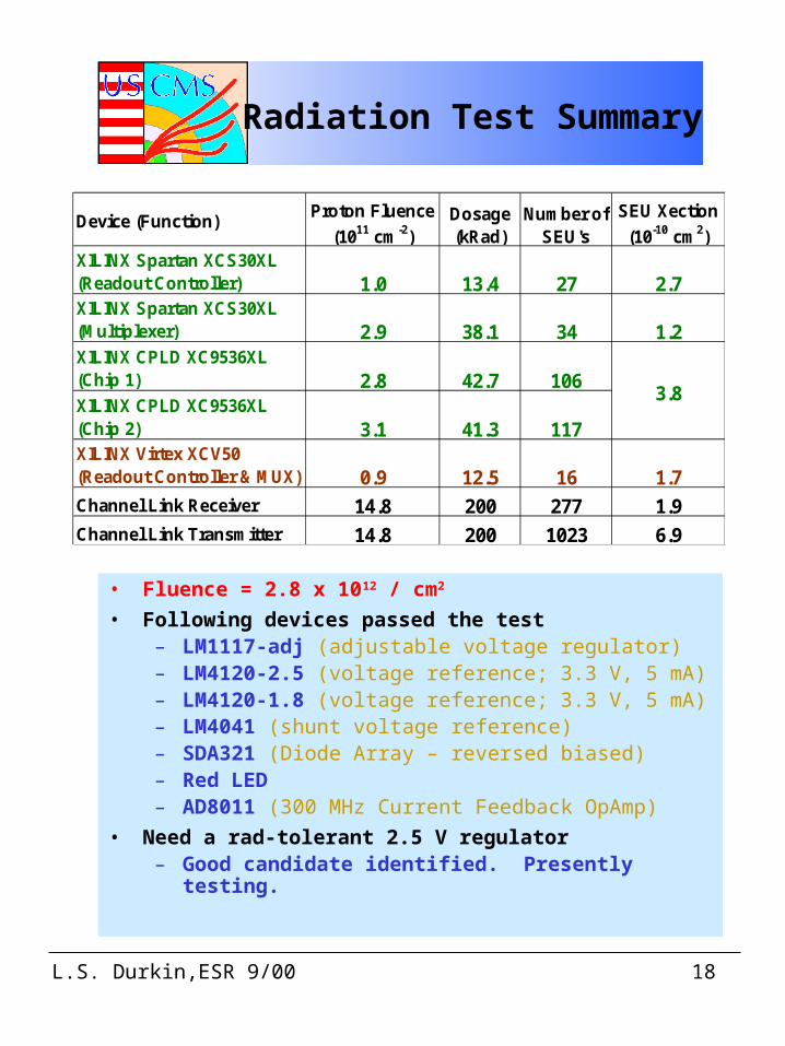
Device (Function)Proton Fluence
(1011 cm-2)Dosage (kRad)
Number of SEU's
SEU Xection
(10-10 cm2)XILINX Spartan XCS30XL (Readout Controller) 1.0 13.4 27 2.7XILINX Spartan XCS30XL (Multiplexer) 2.9 38.1 34 1.2XILINX CPLD XC9536XL (Chip 1) 2.8 42.7 106XILINX CPLD XC9536XL (Chip 2) 3.1 41.3 117XILINX Virtex XCV50 (Readout Controller & MUX) 0.9 12.5 16 1.7Channel Link Receiver 14.8 200 277 1.9Channel Link Transmitter 14.8 200 1023 6.9
3.8
• Fluence = 2.8 x 10¹² / cm2
• Following devices passed the test– LM1117-adj (adjustable voltage regulator)– LM4120-2.5 (voltage reference; 3.3 V, 5 mA)– LM4120-1.8 (voltage reference; 3.3 V, 5 mA) – LM4041 (shunt voltage reference)– SDA321 (Diode Array – reversed biased)– Red LED– AD8011 (300 MHz Current Feedback OpAmp)
• Need a rad-tolerant 2.5 V regulator– Good candidate identified. Presently testing.
Radiation Test Summary
L.S. Durkin,ESR 9/00 19
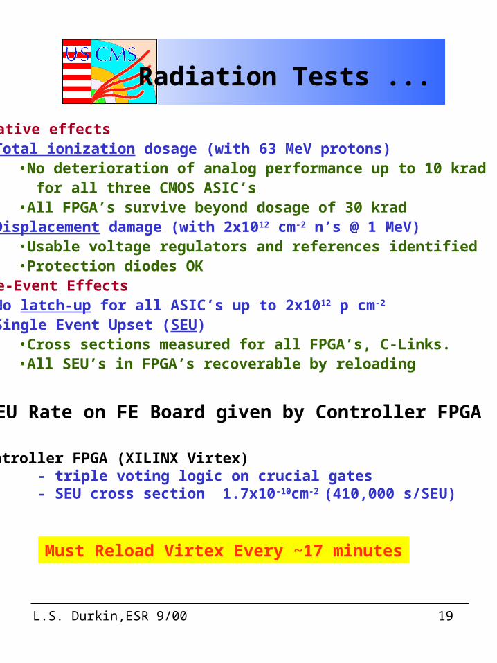
Radiation Tests ...
Cumulative effects–Total ionization dosage (with 63 MeV protons)
•No deterioration of analog performance up to 10 krad for all three CMOS ASIC’s•All FPGA’s survive beyond dosage of 30 krad
–Displacement damage (with 2x1012 cm-2 n’s @ 1 MeV)•Usable voltage regulators and references identified•Protection diodes OK
Single-Event Effects–No latch-up for all ASIC’s up to 2x10¹² p cm-2 –Single Event Upset (SEU)
•Cross sections measured for all FPGA’s, C-Links. •All SEU’s in FPGA’s recoverable by reloading
SEU Rate on FE Board given by Controller FPGA
Controller FPGA (XILINX Virtex) - triple voting logic on crucial gates - SEU cross section 1.7x10⁻¹⁰cm-2 (410,000 s/SEU)
Must Reload Virtex Every ~17 minutes
L.S. Durkin,ESR 9/00 20
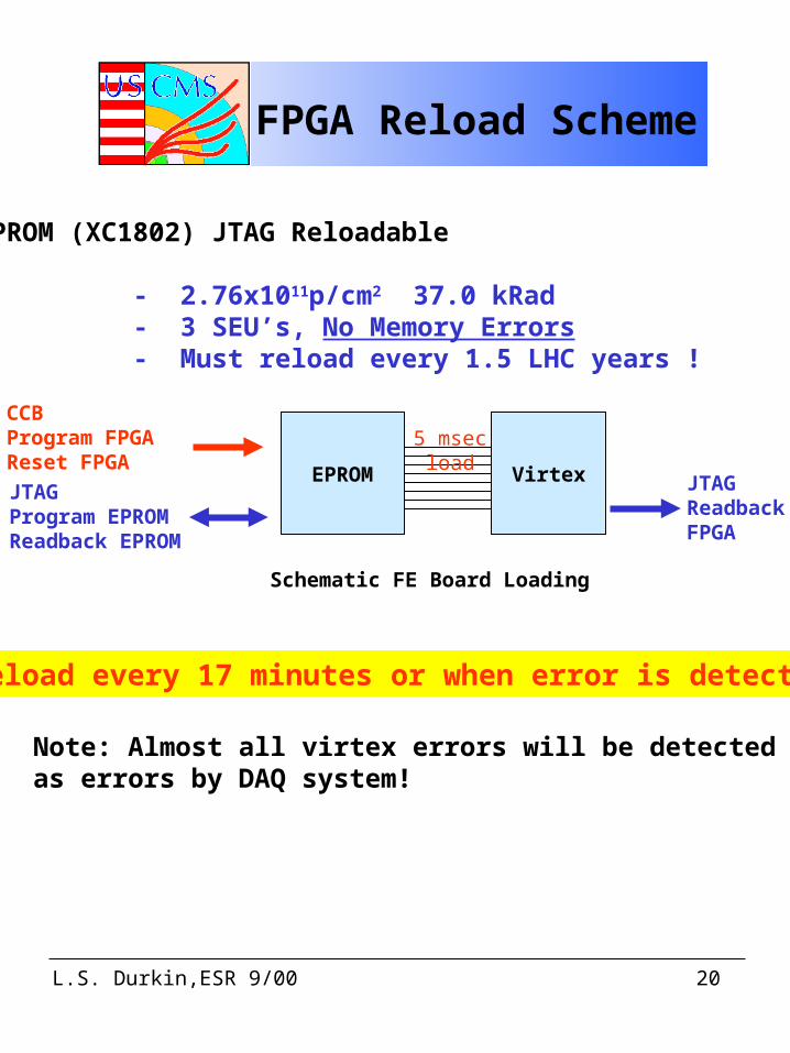
FPGA Reload Scheme
EPROM (XC1802) JTAG Reloadable
- 2.76x10¹¹p/cm2 37.0 kRad - 3 SEU’s, No Memory Errors - Must reload every 1.5 LHC years !
EPROM Virtex
Schematic FE Board Loading
JTAGProgram EPROMReadback EPROM
CCBProgram FPGAReset FPGA
JTAGReadbackFPGA
5 msecload
Reload every 17 minutes or when error is detected
Note: Almost all virtex errors will be detectedas errors by DAQ system!
L.S. Durkin,ESR 9/00 21
Magnetic Field
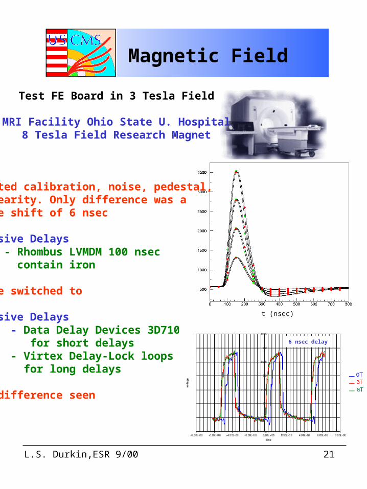
Test FE Board in 3 Tesla Field
MRI Facility Ohio State U. Hospital8 Tesla Field Research Magnet
Tested calibration, noise, pedestal,linearity. Only difference was a time shift of 6 nsec
Passive Delays - Rhombus LVMDM 100 nsec contain iron
have switched to
Passive Delays - Data Delay Devices 3D7105 for short delays - Virtex Delay-Lock loops for long delays
no difference seen
t (nsec)
6 nsec delay
L.S. Durkin,ESR 9/00 22
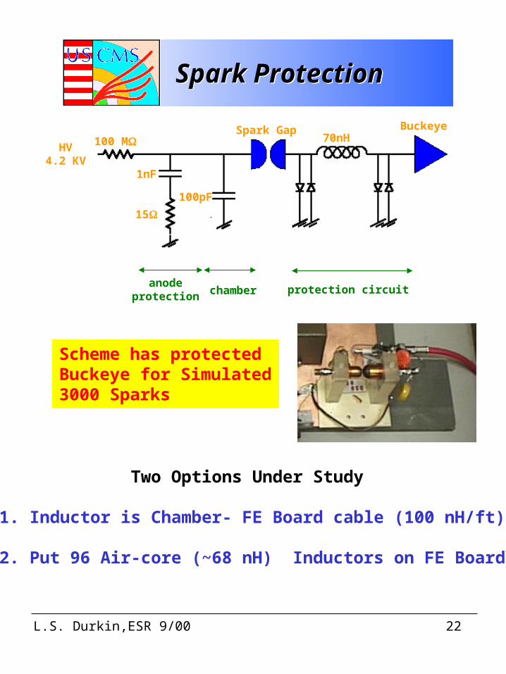
Spark ProtectionSpark Protection
HV4.2 KV
100 M
1nF
15
100pF
Spark Gap Buckeye70nH
anodeprotection chamber protection circuit
Two Options Under Study
1. Inductor is Chamber- FE Board cable (100 nH/ft)
2. Put 96 Air-core (~68 nH) Inductors on FE Board
Scheme has protectedBuckeye for Simulated3000 Sparks
L.S. Durkin,ESR 9/00 23
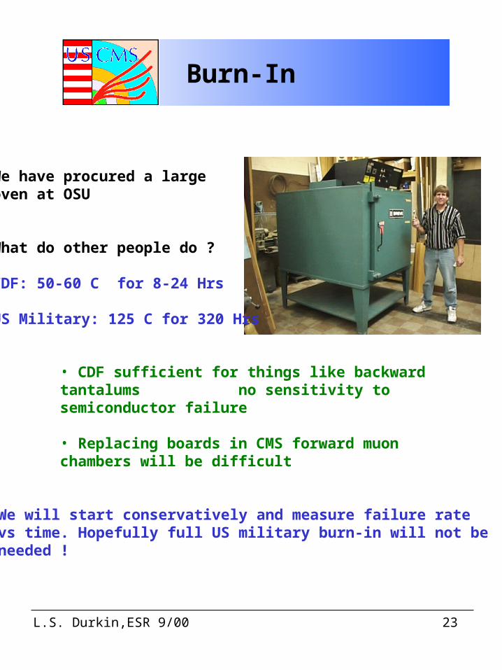
Burn-In
We have procured a large oven at OSU
What do other people do ?
CDF: 50-60 C for 8-24 Hrs
US Military: 125 C for 320 Hrs
• CDF sufficient for things like backward tantalums no sensitivity to semiconductor failure
• Replacing boards in CMS forward muon chambers will be difficult
We will start conservatively and measure failure ratevs time. Hopefully full US military burn-in will not beneeded !
L.S. Durkin,ESR 9/00 24
Production
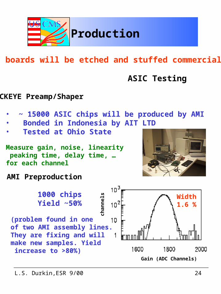
PC boards will be etched and stuffed commercially
ASIC Testing
BUCKEYE Preamp/Shaper
• ~ 15000 ASIC chips will be produced by AMI• Bonded in Indonesia by AIT LTD• Tested at Ohio State
Measure gain, noise, linearity peaking time, delay time, …for each channel
AMI Preproduction
1000 chips Yield ~50%
(problem found in one of two AMI assembly lines. They are fixing and will make new samples. Yield increase to >80%)
Gain (ADC Channels)
ch
an
ne
l s Width1.6 %
L.S. Durkin,ESR 9/00 25
Production …
SCA ASIC
• AMI will manufacture wafers• AMI will measure chips guaranteeing quality• AMI will bond chips
Comparator ASIC • Alcatel will manufacture wafers• an outside company will measure chips • Chips will be bonded in Hong Kong
Alcatel Preproduction
• yield 66 % (working on it)• chips are excellent
L.S. Durkin,ESR 9/00 26
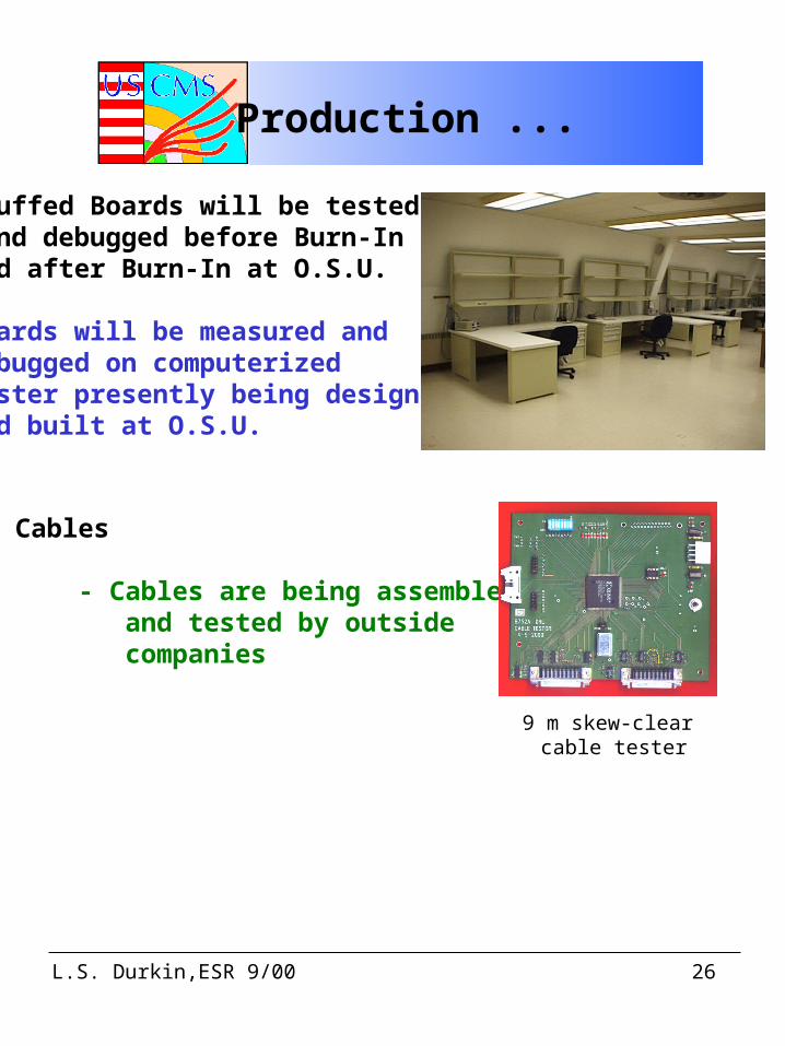
Stuffed Boards will be tested and debugged before Burn-Inand after Burn-In at O.S.U.
Boards will be measured and debugged on computerized tester presently being designedand built at O.S.U.
Data Cables - Cables are being assembled and tested by outside companies
9 m skew-clear cable tester
Production ...
L.S. Durkin,ESR 9/00 27
Material Safety
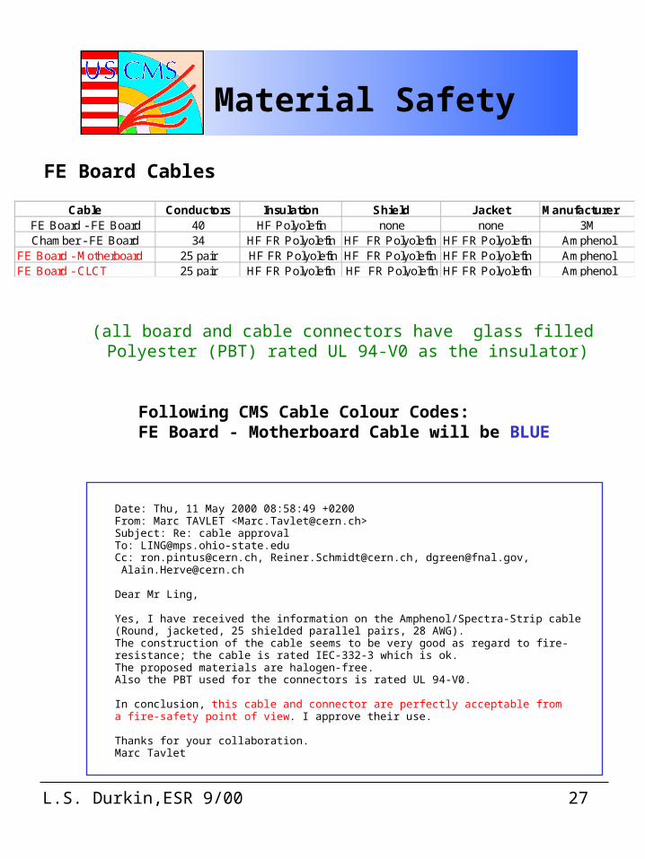
Cable Conductors Insulation Shield Jacket ManufacturerFE Board - FE Board 40 HF Polyolefin none none 3MChamber - FE Board 34 HF FR Polyolefin HF FR Polyolefin HF FR Polyolefin Amphenol
FE Board - Motherboard 25 pair HF FR Polyolefin HF FR Polyolefin HF FR Polyolefin AmphenolFE Board - CLCT 25 pair HF FR Polyolefin HF FR Polyolefin HF FR Polyolefin Amphenol
FE Board Cables
(all board and cable connectors have glass filled Polyester (PBT) rated UL 94-V0 as the insulator)
Date: Thu, 11 May 2000 08:58:49 +0200From: Marc TAVLET <[email protected]>Subject: Re: cable approvalTo: [email protected]: [email protected], [email protected], [email protected], [email protected]
Dear Mr Ling,
Yes, I have received the information on the Amphenol/Spectra-Strip cable(Round, jacketed, 25 shielded parallel pairs, 28 AWG).The construction of the cable seems to be very good as regard to fire-resistance; the cable is rated IEC-332-3 which is ok.The proposed materials are halogen-free.Also the PBT used for the connectors is rated UL 94-V0.
In conclusion, this cable and connector are perfectly acceptable froma fire-safety point of view. I approve their use.
Thanks for your collaboration.Marc Tavlet
Following CMS Cable Colour Codes: FE Board - Motherboard Cable will be BLUE
L.S. Durkin,ESR 9/00 28
Maintenance
Ohio State University will maintain the FE Boards
10 % Spare Boards will be Built
We anticipate swapping bad boards duringaccesses and fixing them.
Each board has a unique electronic serial number.Swaps can be monitored using software.
Click to edit Master title style
Click to edit Master title styleConclusion
Cathode FE Board MeetsAll Design Specifiations!
It is time to start procuring parts and begin manufacturing...