cathodic protection use on tank bottoms & underground piping in
TRANSCRIPT
IEEE PES
Cathodic Protection Use On Tank Bottoms
& Underground Piping In Power Generation Plants
PG&E OfficeSan Francisco
January 18, 2007Craig K. Meier
Corrosion Control Incorporated
IEEE PES
• Corrosion process for tanks and piping• Principles of cathodic protection• Effects of coatings• Cathodic protection design requirements• Selecting the proper system• Construction implementation issues• Compliance testing• Continued monitoring and maintenance
IEEE PES
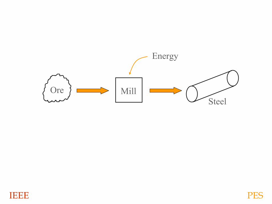
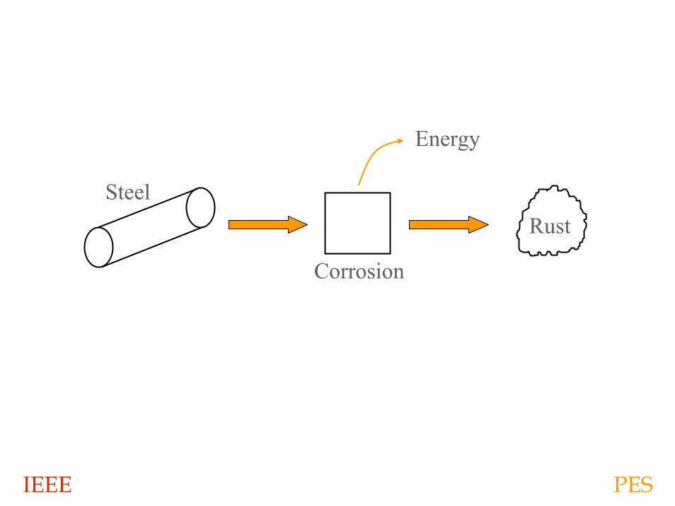
Ore MillSteel
Energy
IEEE PES
IEEE PES
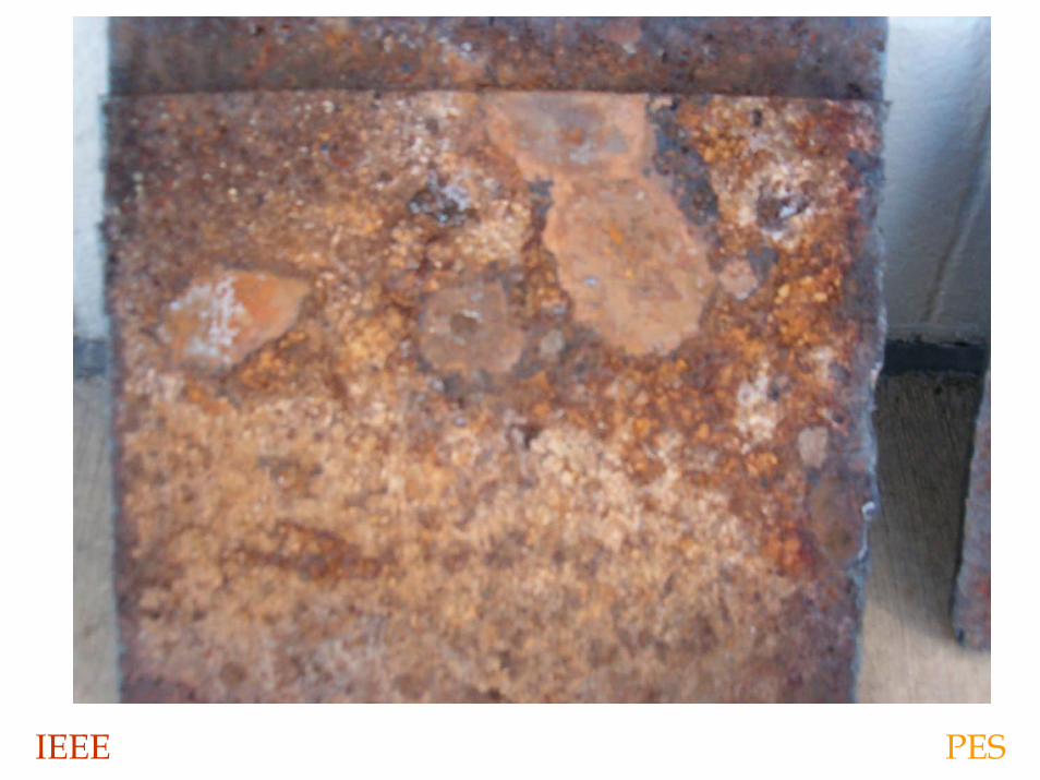
Rust
Corrosion
Steel
Energy
IEEE PES
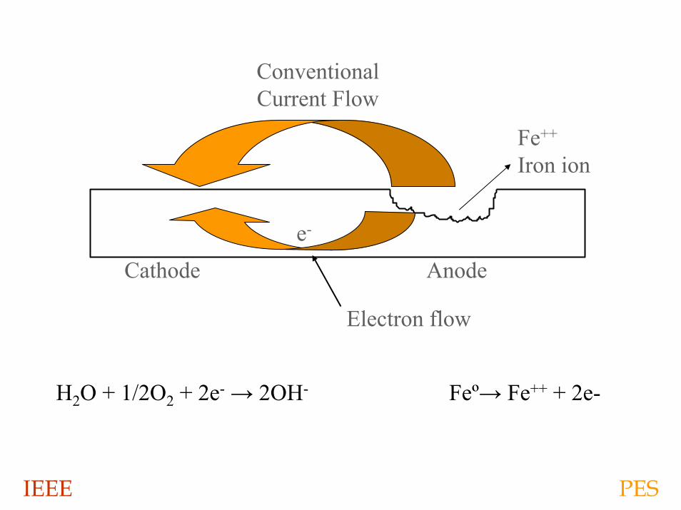
Fe++
Iron ion
Cathode Anodee-
Electron flow
H2O + 1/2O2 + 2e- → 2OH- Feº→ Fe++ + 2e-
ConventionalCurrent Flow
IEEE PES
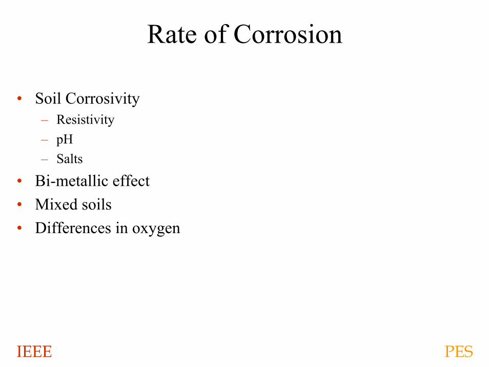
Rate of Corrosion
• Soil Corrosivity– Resistivity– pH– Salts
• Bi-metallic effect• Mixed soils• Differences in oxygen
IEEE PES
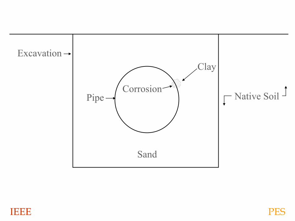
Corrosion
Clay
Sand
Pipe
Excavation
Native Soil
IEEE PES
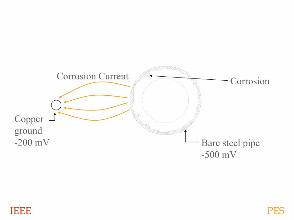
Corrosion
Bare steel pipe-500 mV
Copperground-200 mV
Corrosion Current
IEEE PES
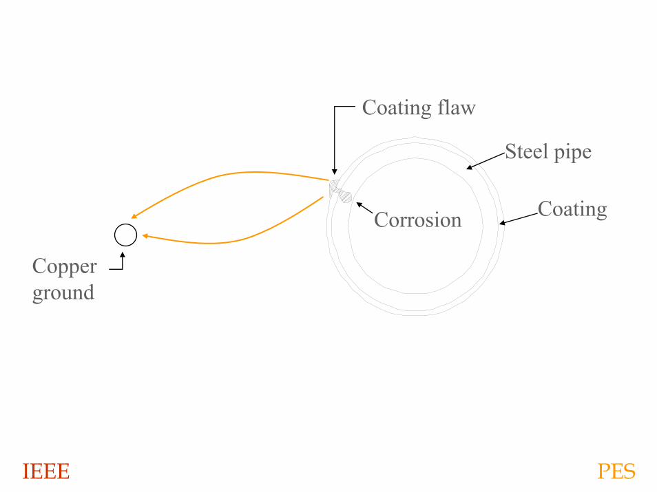
Copperground
Corrosion
Steel pipe
Coating
Coating flaw
IEEE PES
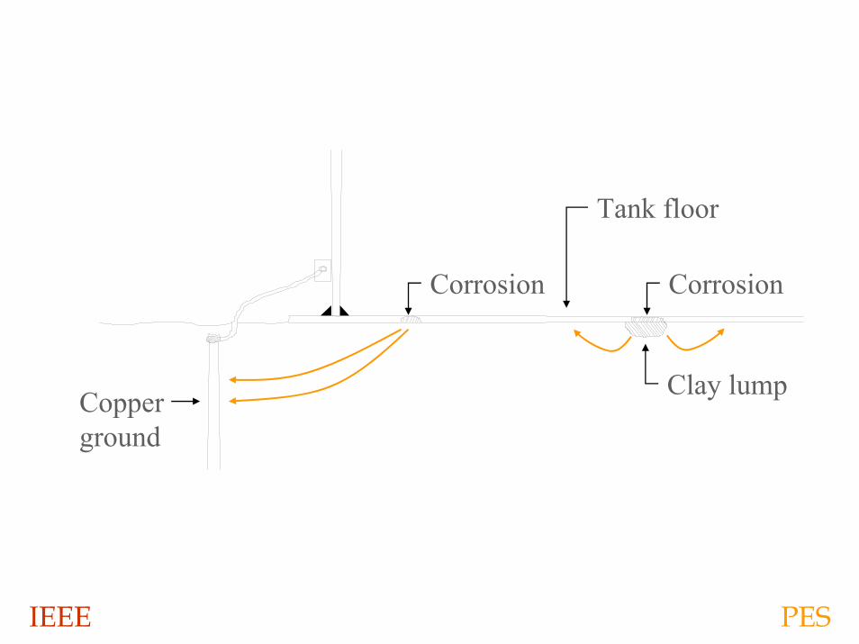
Corrosion
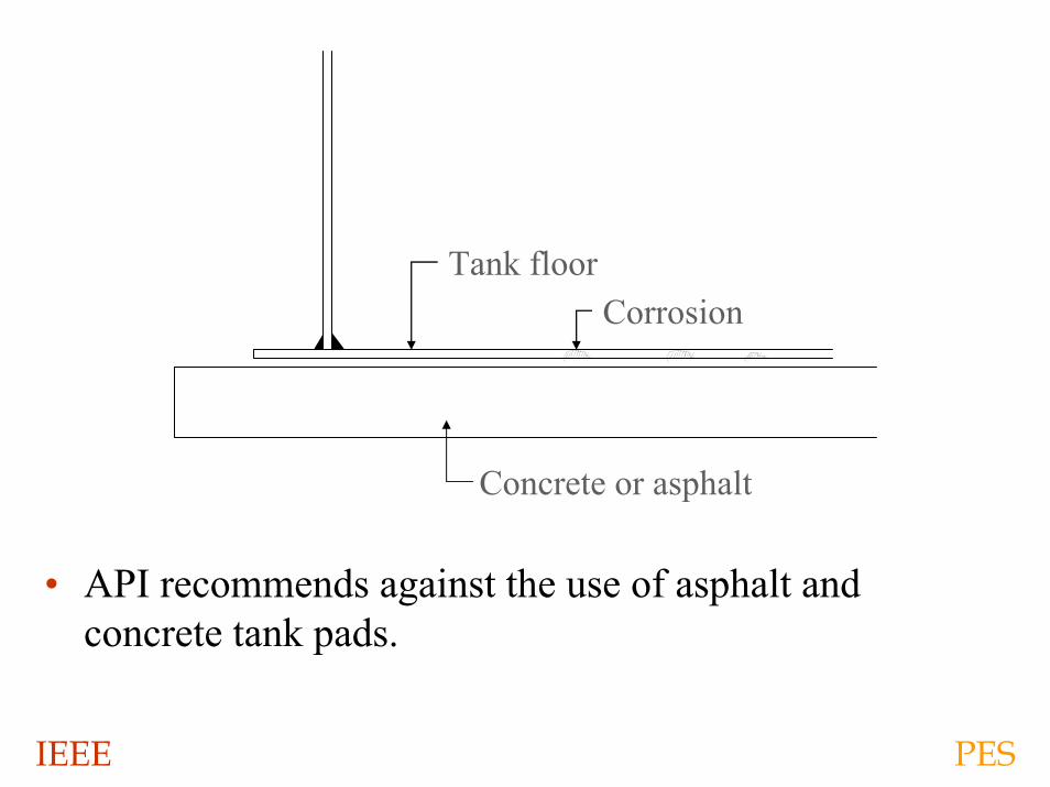
Tank floor
Clay lumpCopperground
Corrosion
IEEE PES
IEEE PES
• API recommends against the use of asphalt and concrete tank pads.
Concrete or asphalt
Tank floorCorrosion

IEEE PES
IEEE PES
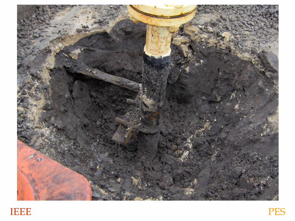
Corrosion Losses
• Will occur in all plants• Rate of loss dependent on soil and materials used• Coatings alone do not stop soil corrosion• Care during construction can significantly reduce losses
IEEE PES
Corrosion Control
• Material selection• Bedding• Coatings• Cathodic Protection
IEEE PES
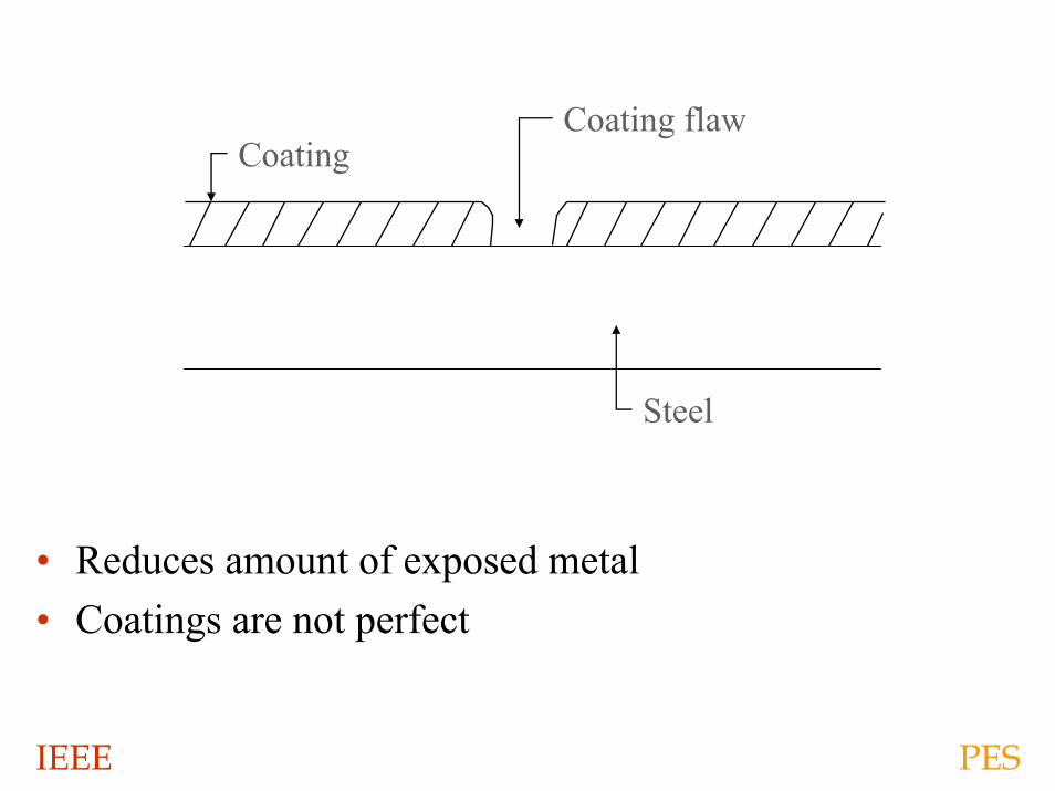
• Reduces amount of exposed metal• Coatings are not perfect
Steel
Coating flawCoating
IEEE PES
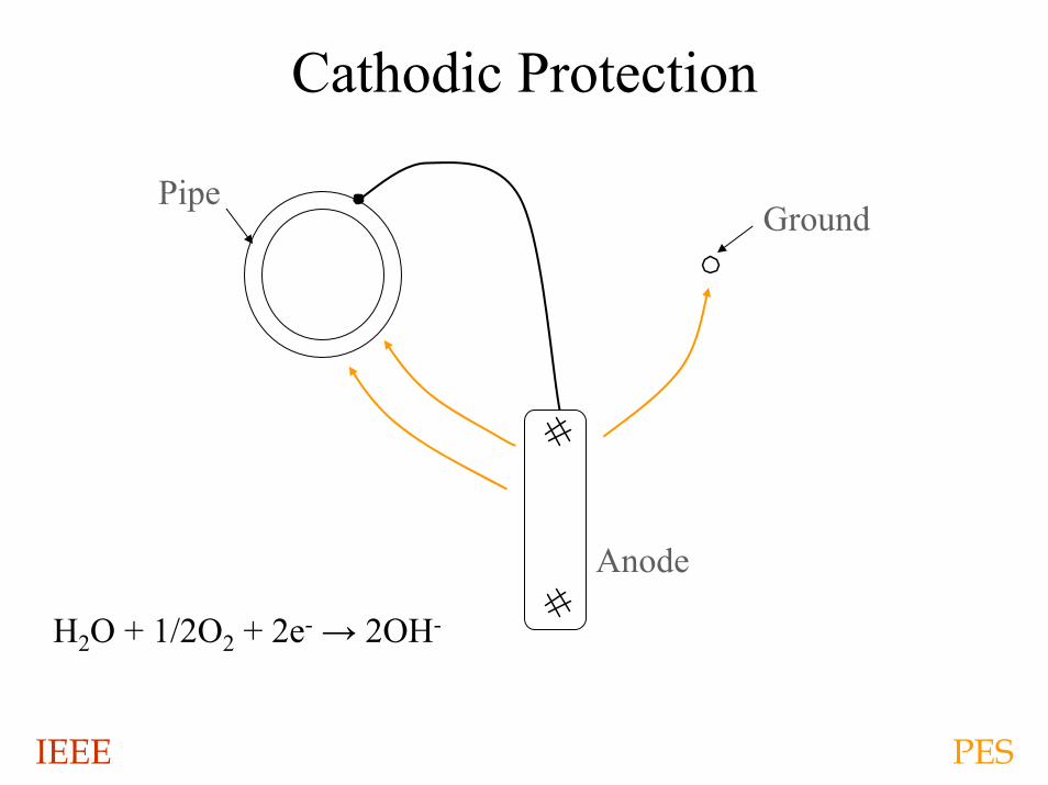
Cathodic Protection
H2O + 1/2O2 + 2e- → 2OH-
Pipe
Anode
Ground
IEEE PES
Cathodic Protection
• Galvanic
• Impressed Current
IEEE PES
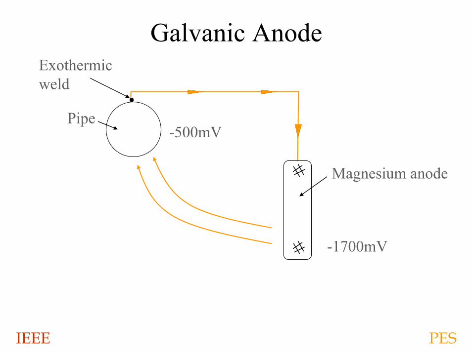
Galvanic Anode
Pipe-500mV
Magnesium anode
-1700mV
Exothermicweld
IEEE PES
Galvanic Cathodic Protection
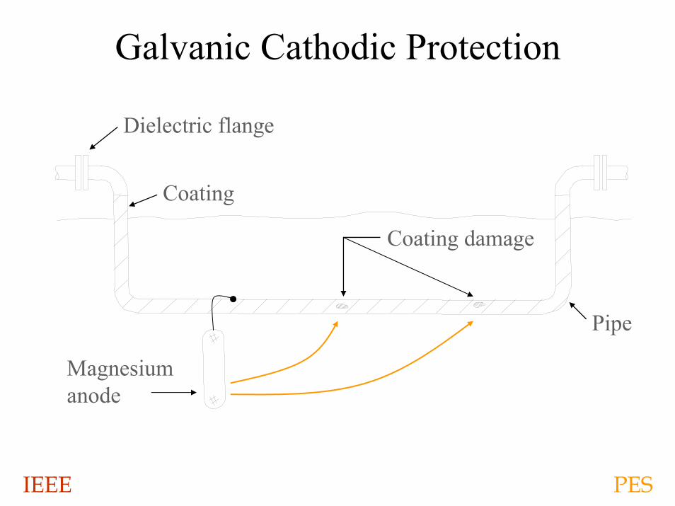
• Galvanic anodes have a limited current output, 10 to 30 milliamperes per anode.
• Due to the limited current output, the use of galvanic anodes is limited to coated and electrically isolated underground piping and underground tanks.
IEEE PES
Galvanic Cathodic Protection
Magnesiumanode
Coating damage
Pipe
Coating
Dielectric flange
IEEE PES
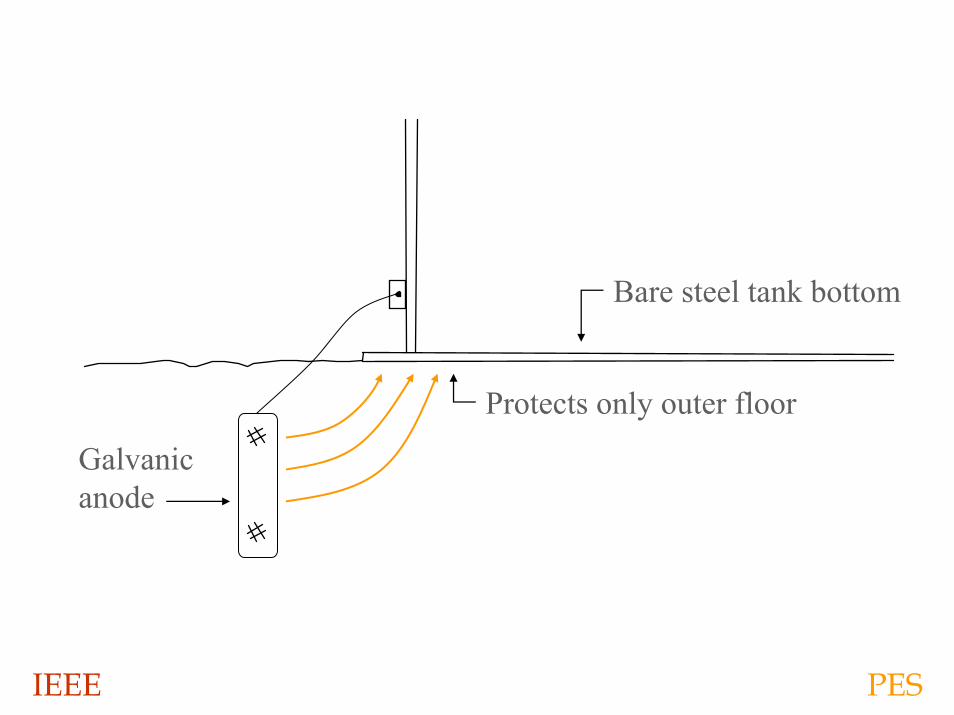
Galvanicanode
Protects only outer floor
Bare steel tank bottom
IEEE PES
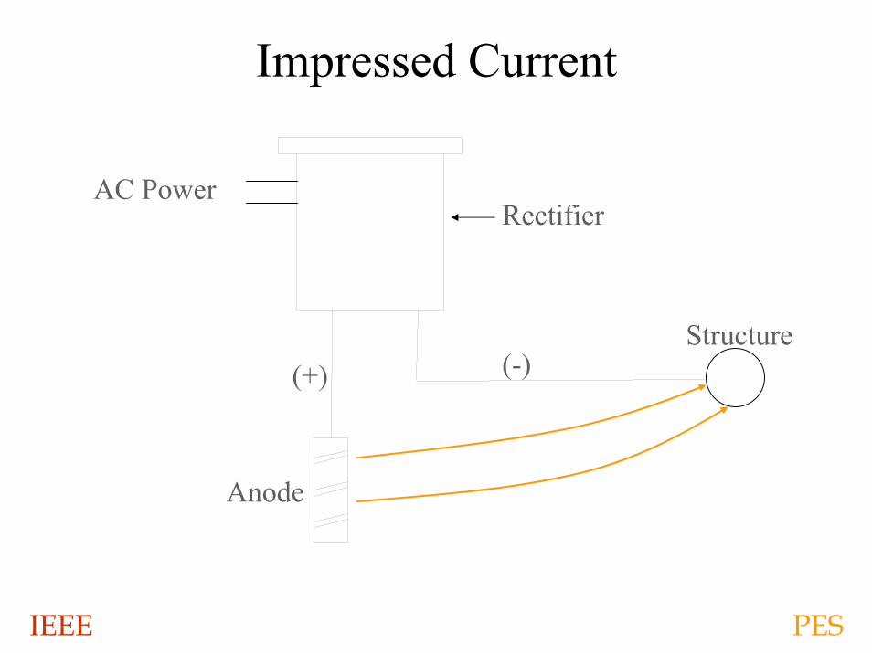
Impressed Current
AC PowerRectifier
Anode
Structure(+) (-)
IEEE PES
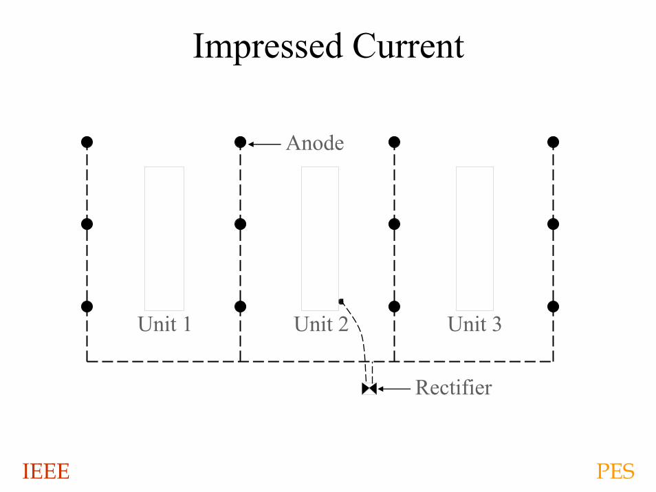
Impressed Current
Unit 1 Unit 3Unit 2
Rectifier
Anode
IEEE PES
IEEE PES
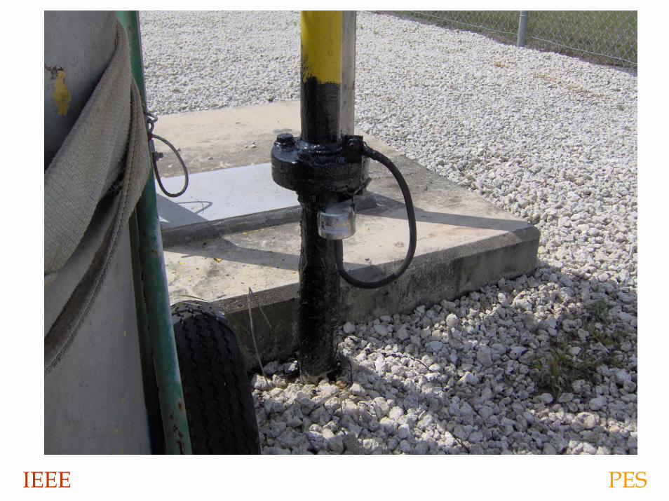
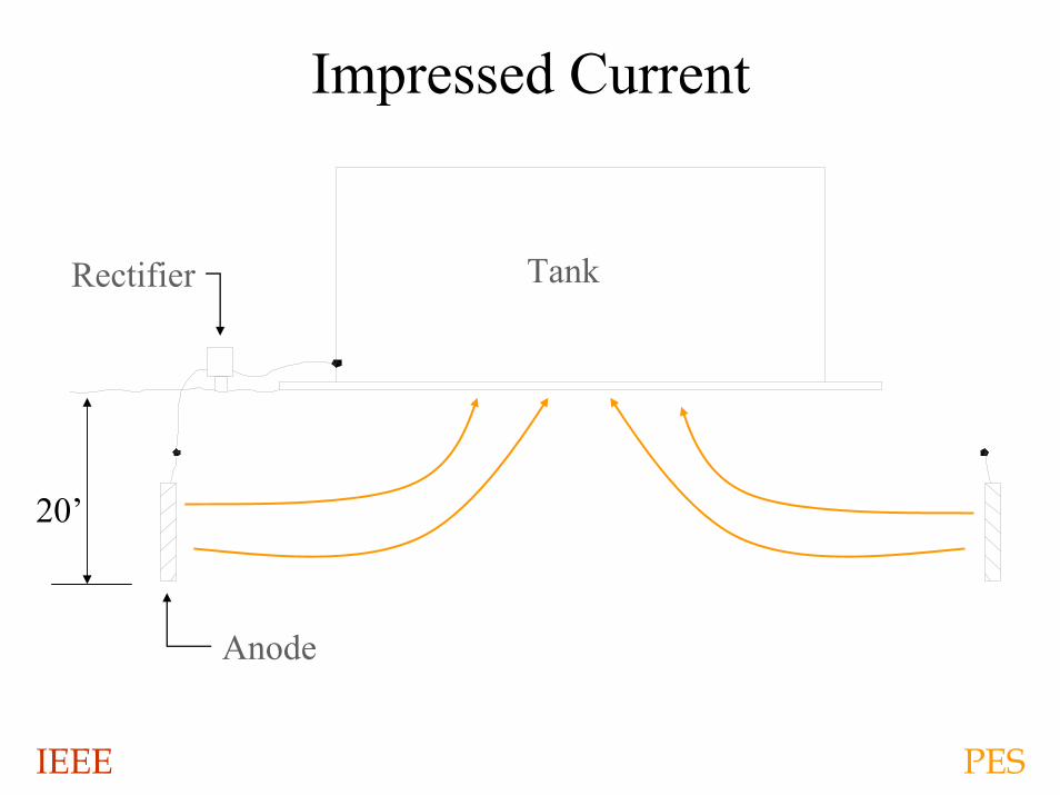
Impressed Current
20’
Rectifier
Anode
Tank
IEEE PES
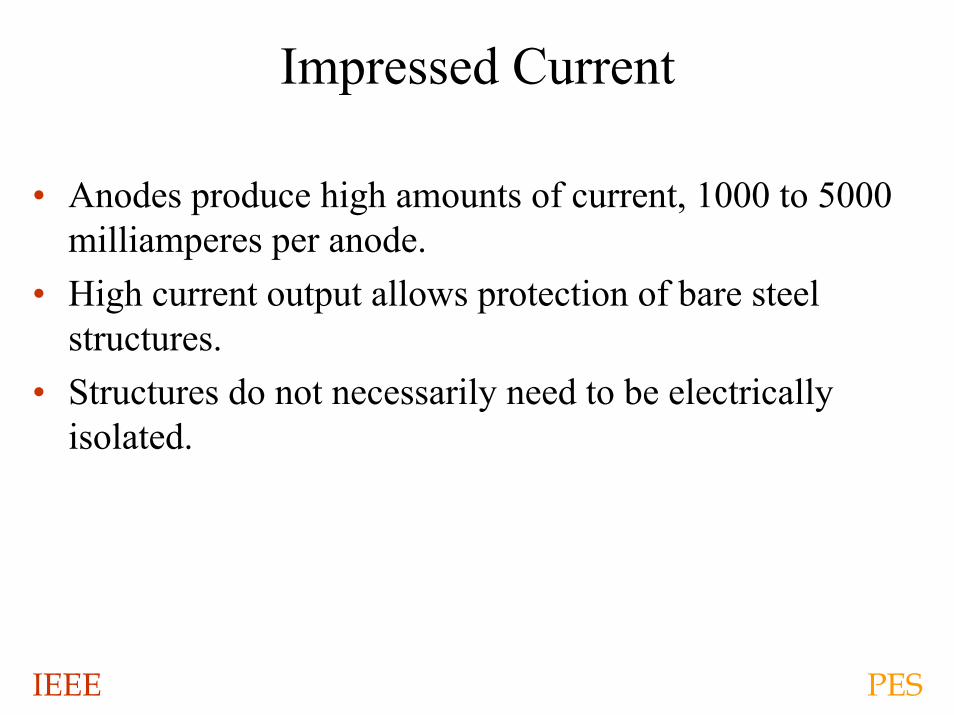
Impressed Current
• Anodes produce high amounts of current, 1000 to 5000 milliamperes per anode.
• High current output allows protection of bare steel structures.
• Structures do not necessarily need to be electrically isolated.
IEEE PES
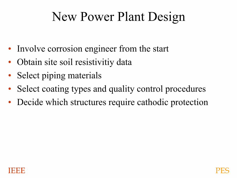
New Power Plant Design
• Involve corrosion engineer from the start• Obtain site soil resistivitiy data• Select piping materials• Select coating types and quality control procedures• Decide which structures require cathodic protection
IEEE PES
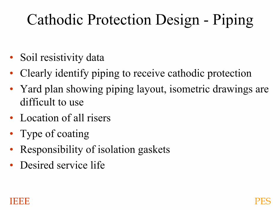
Cathodic Protection Design - Piping
• Soil resistivity data• Clearly identify piping to receive cathodic protection• Yard plan showing piping layout, isometric drawings are
difficult to use• Location of all risers• Type of coating• Responsibility of isolation gaskets• Desired service life
IEEE PES
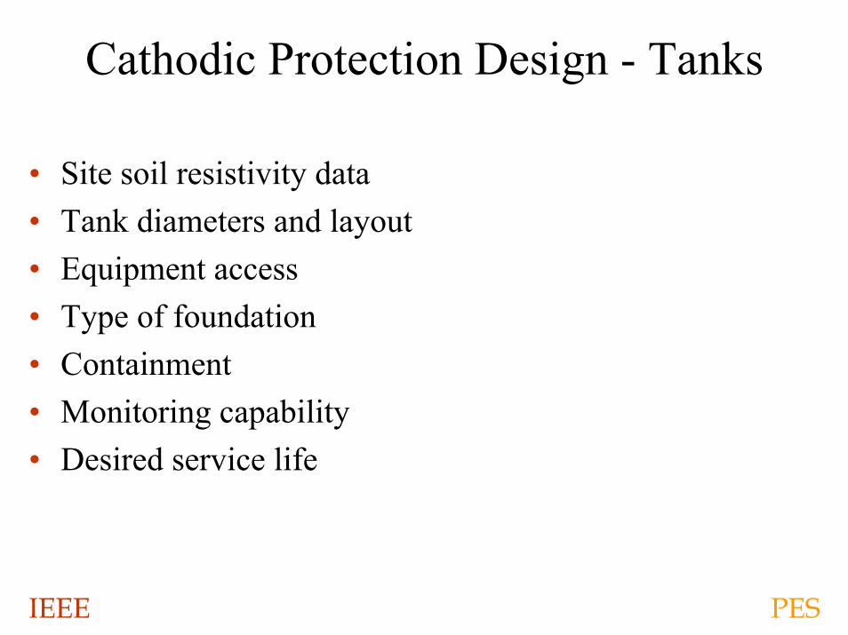
Cathodic Protection Design - Tanks
• Site soil resistivity data• Tank diameters and layout• Equipment access• Type of foundation• Containment• Monitoring capability• Desired service life
IEEE PES
Design Options
• Design documents issued in construction plans• Contract responsible for cathodic design
IEEE PES
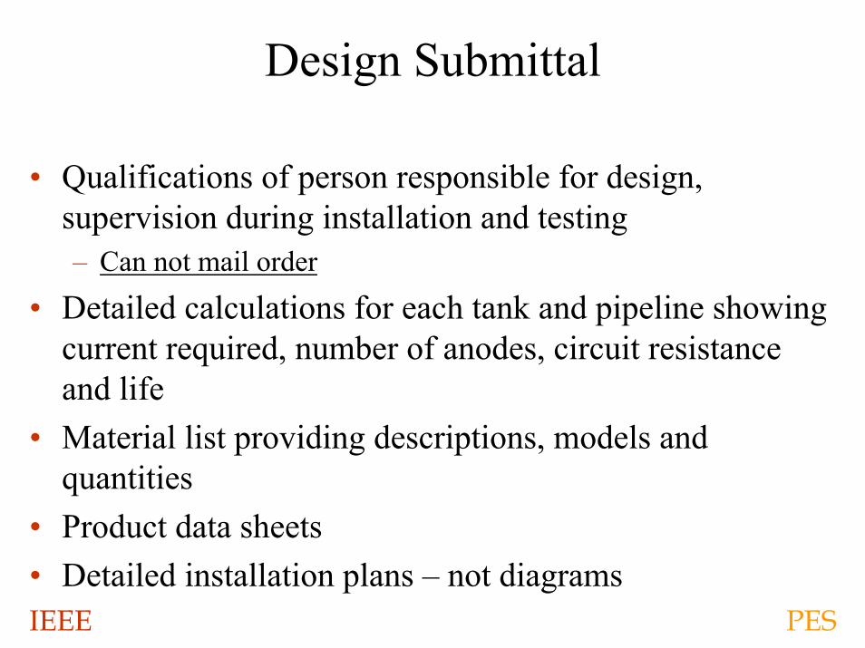
Design Submittal
• Qualifications of person responsible for design, supervision during installation and testing– Can not mail order
• Detailed calculations for each tank and pipeline showing current required, number of anodes, circuit resistance and life
• Material list providing descriptions, models and quantities
• Product data sheets• Detailed installation plans – not diagrams
IEEE PES
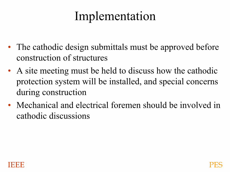
Implementation
• The cathodic design submittals must be approved before construction of structures
• A site meeting must be held to discuss how the cathodic protection system will be installed, and special concerns during construction
• Mechanical and electrical foremen should be involved in cathodic discussions
IEEE PES
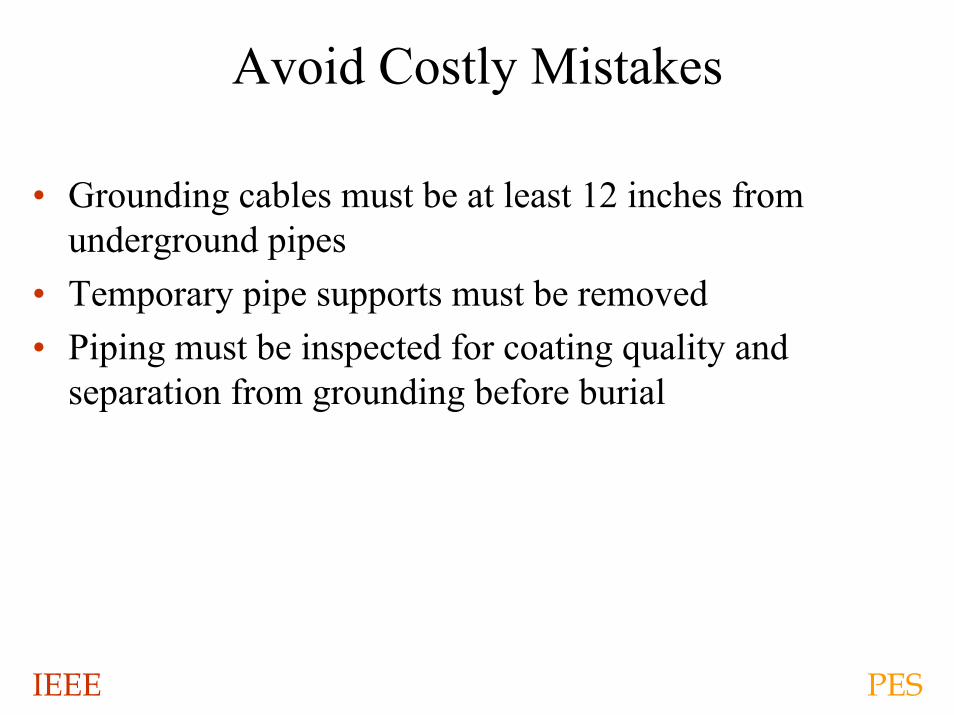
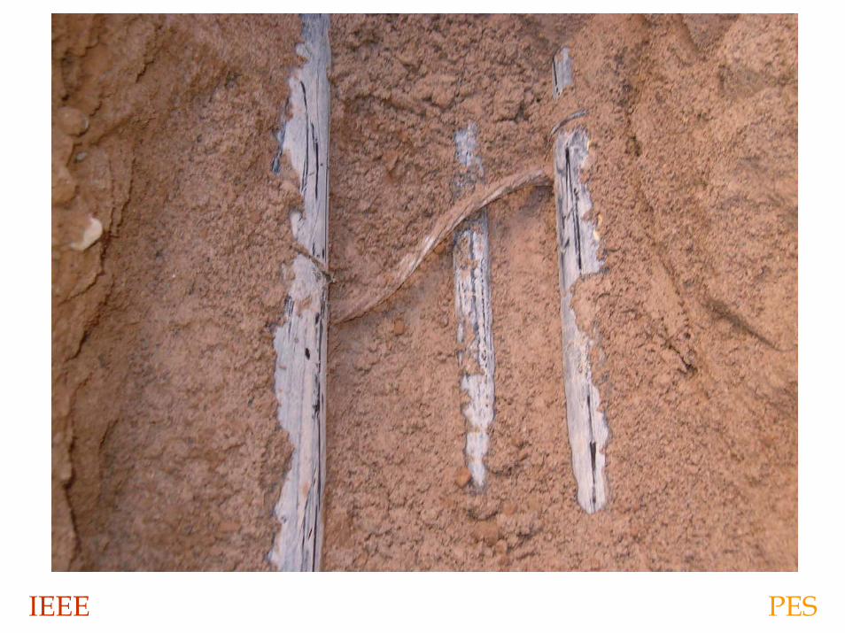
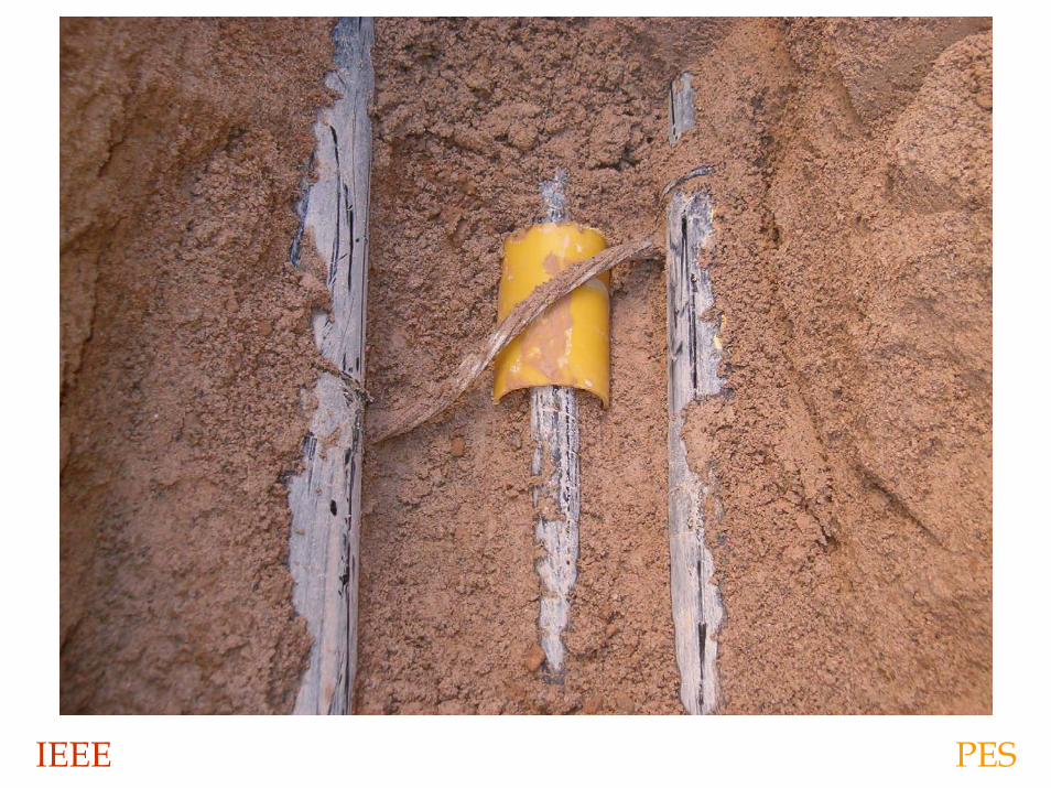
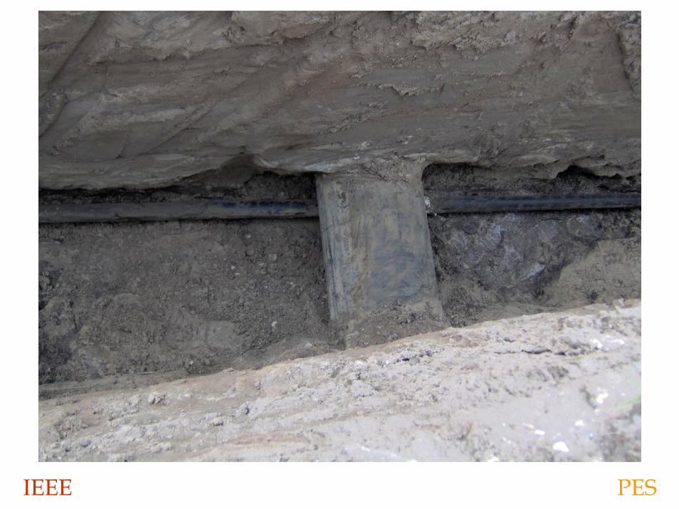
Avoid Costly Mistakes
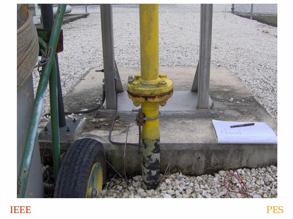
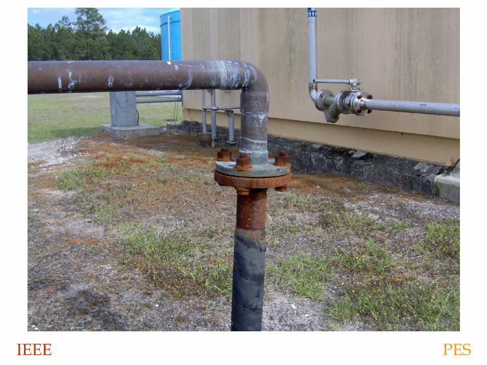
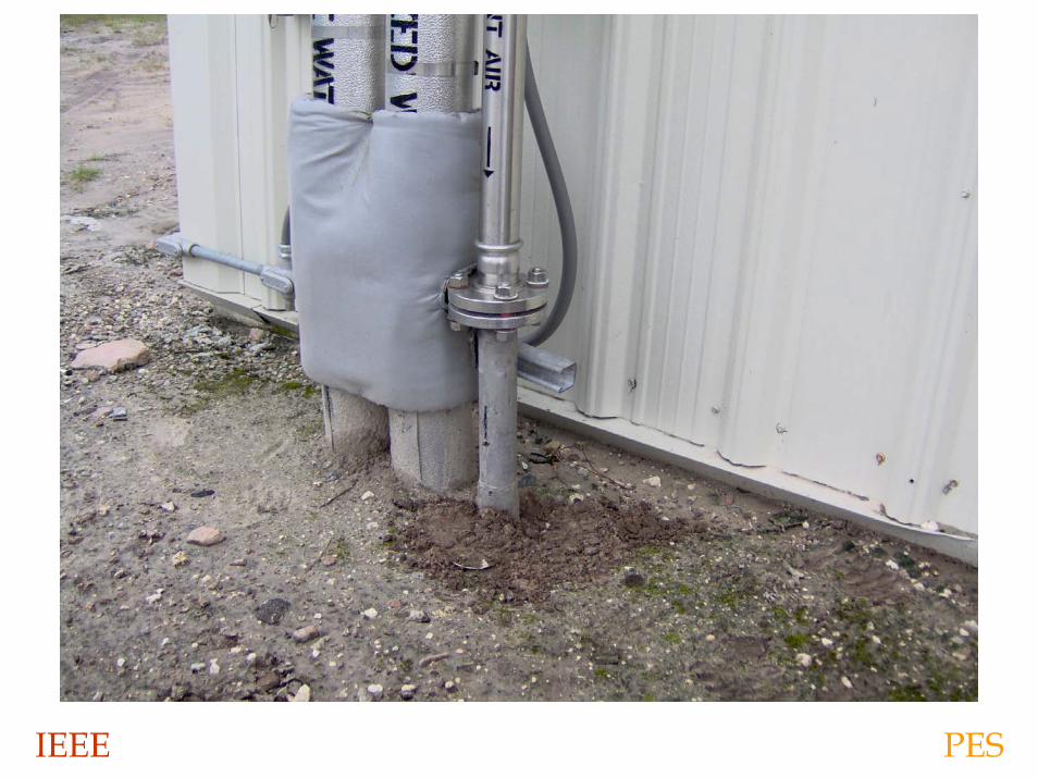
• Grounding cables must be at least 12 inches from underground pipes
• Temporary pipe supports must be removed• Piping must be inspected for coating quality and
separation from grounding before burial
IEEE PES
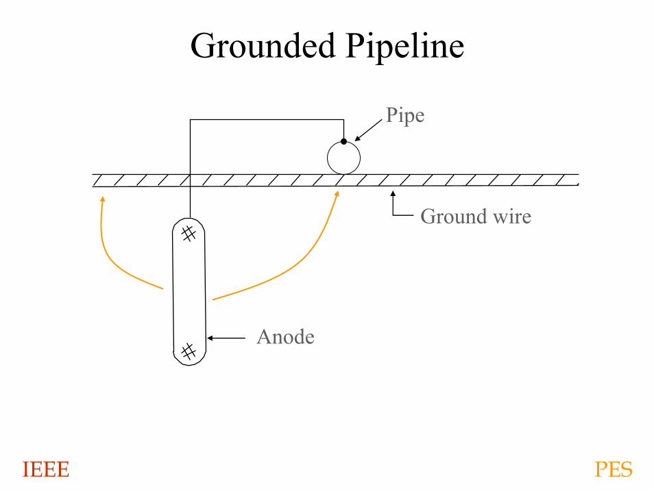
Grounded Pipeline
Pipe
Ground wire
Anode
IEEE PES
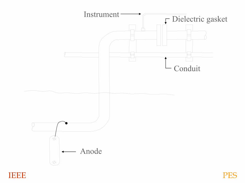
Dielectric gasketInstrument
Conduit
Anode
IEEE PES
IEEE PES
IEEE PES
IEEE PES
IEEE PES
IEEE PES
IEEE PES
IEEE PES
IEEE PES
IEEE PES
IEEE PES
IEEE PES
IEEE PES
IEEE PES
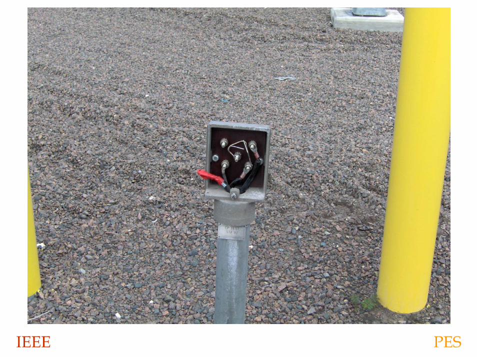
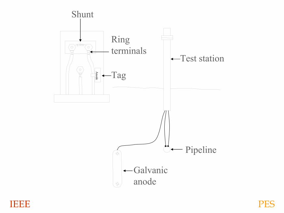
Test station
Galvanicanode
Tag
Shunt
Anode
Pipeline
Ring terminals
IEEE PES
IEEE PES
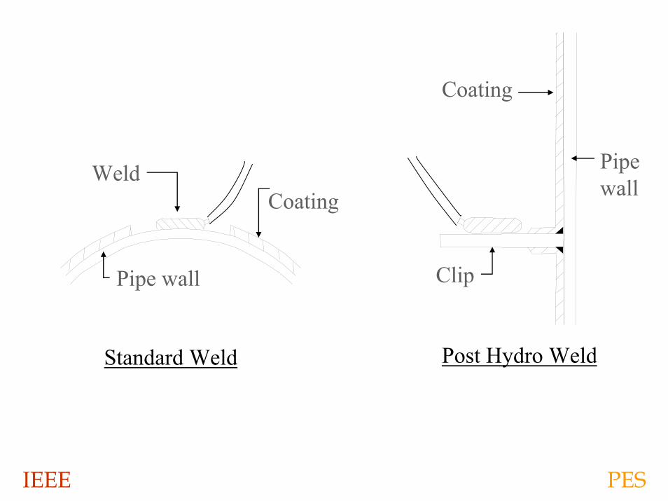
Coating
Standard Weld
Weld
Pipe wall
Post Hydro Weld
Clip
Coating
Pipewall
IEEE PES
IEEE PES
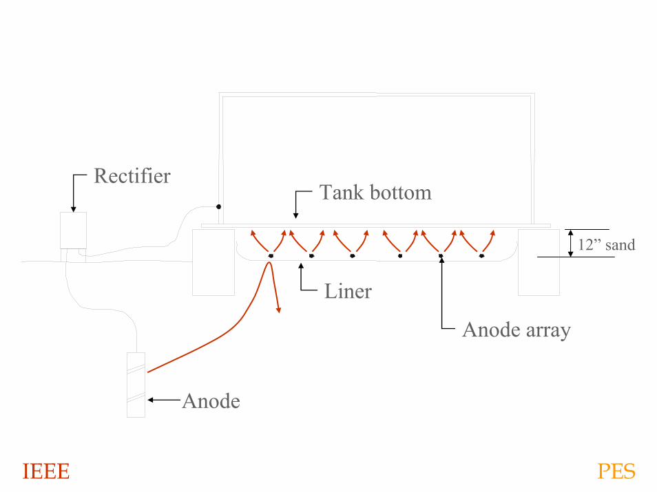
Anode
RectifierTank bottom
Liner
Anode array
12” sand
IEEE PES
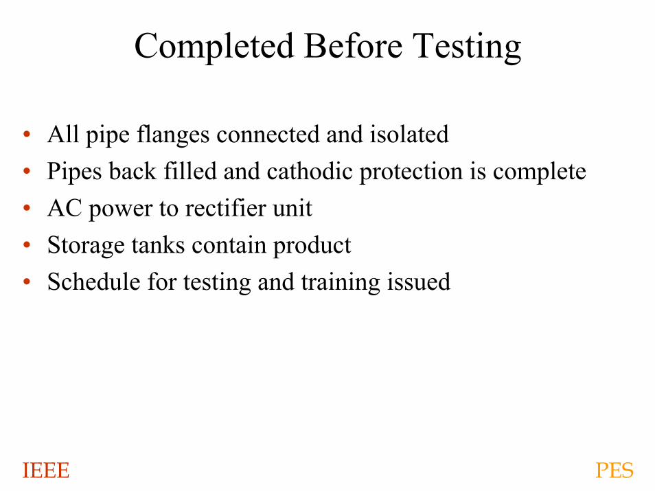
Completed Before Testing
• All pipe flanges connected and isolated• Pipes back filled and cathodic protection is complete• AC power to rectifier unit• Storage tanks contain product• Schedule for testing and training issued
IEEE PES
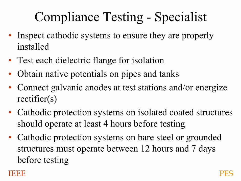
Compliance Testing - Specialist• Inspect cathodic systems to ensure they are properly
installed• Test each dielectric flange for isolation• Obtain native potentials on pipes and tanks• Connect galvanic anodes at test stations and/or energize
rectifier(s)• Cathodic protection systems on isolated coated structures
should operate at least 4 hours before testing• Cathodic protection systems on bare steel or grounded
structures must operate between 12 hours and 7 days before testing
IEEE PES
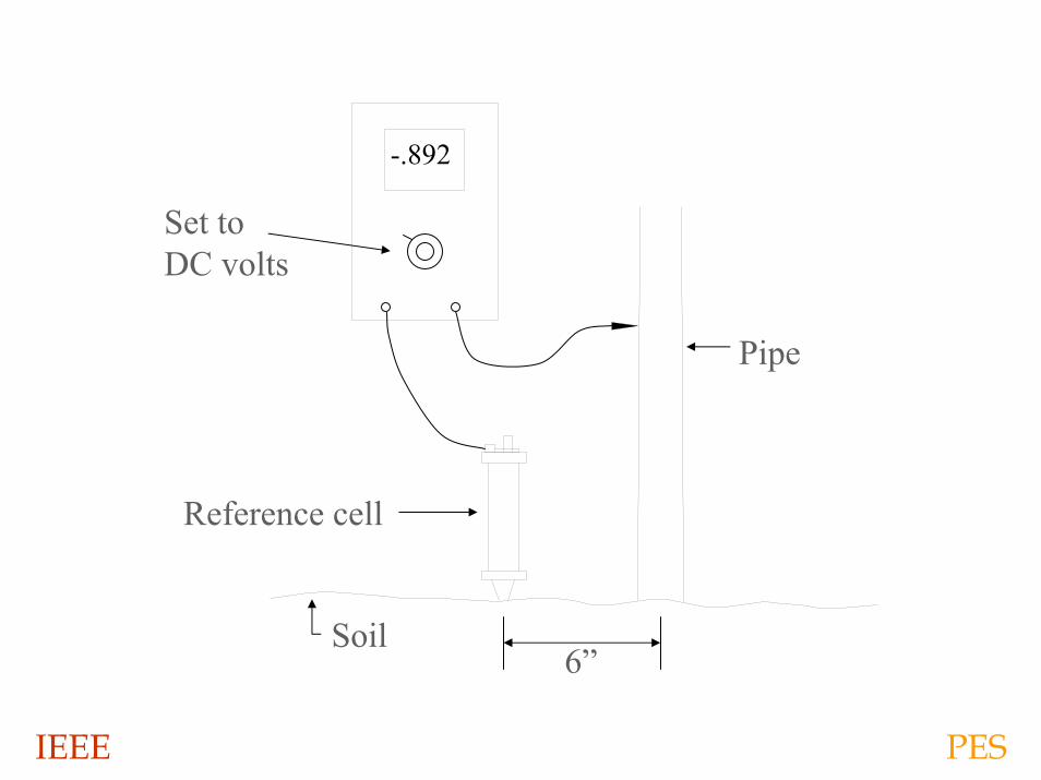
Soil
Set toDC volts
-.892
Pipe
Reference cell
6”
IEEE PES
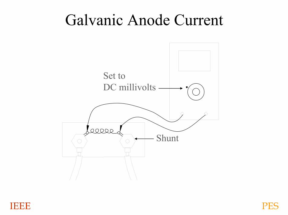
Galvanic Anode Current
Shunt
Set to DC millivolts
IEEE PES
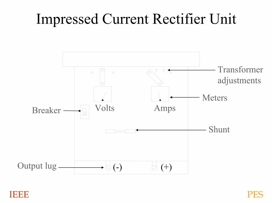
Impressed Current Rectifier Unit
Shunt
Meters
Transformeradjustments
AmpsVolts
(-) (+)
Breaker
Output lug
IEEE PES
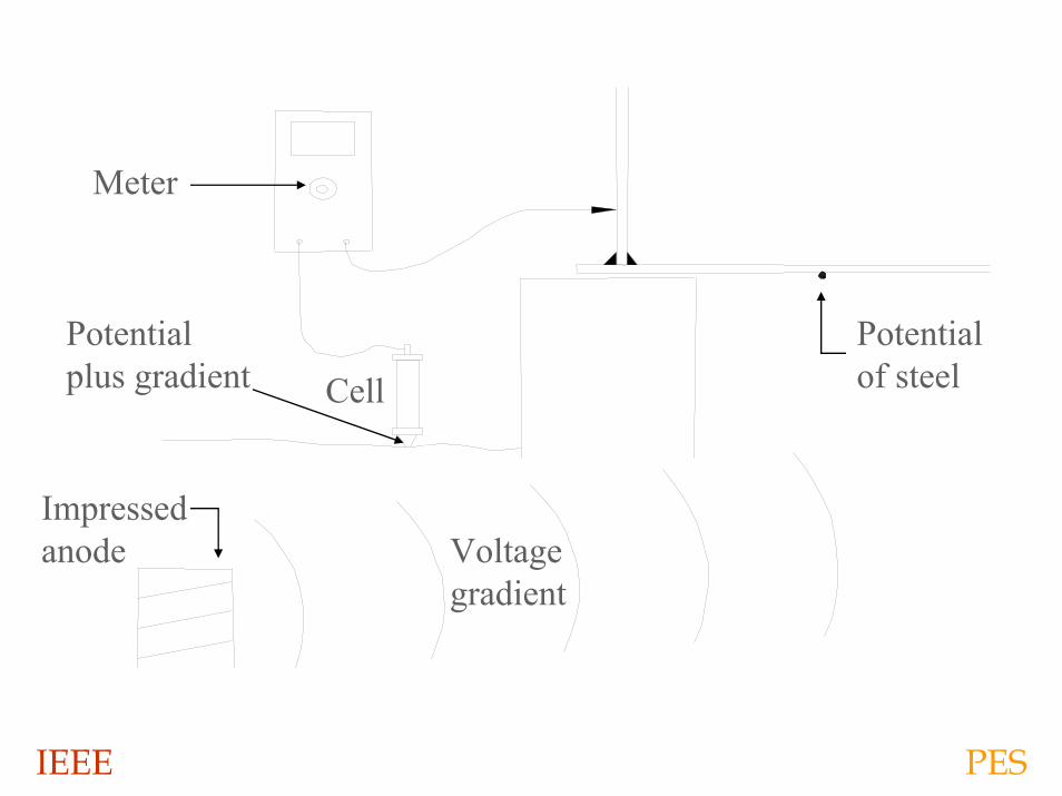
Impressedanode Voltage
gradient
CellPotentialplus gradient
Potentialof steel
Meter
IEEE PES
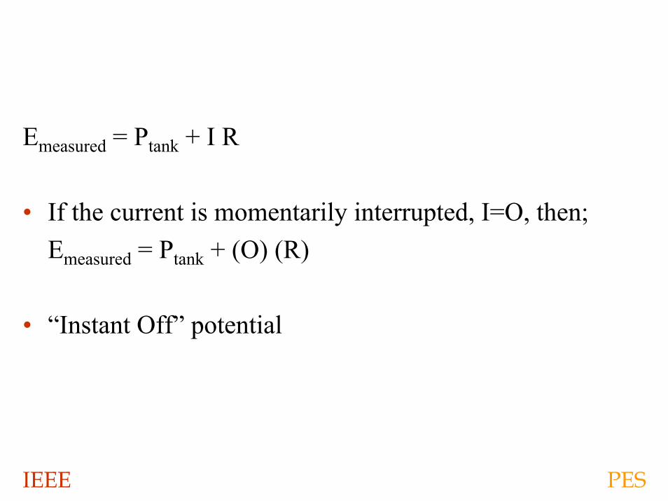
Emeasured = Ptank + I R
• If the current is momentarily interrupted, I=O, then;Emeasured = Ptank + (O) (R)
• “Instant Off” potential
IEEE PES
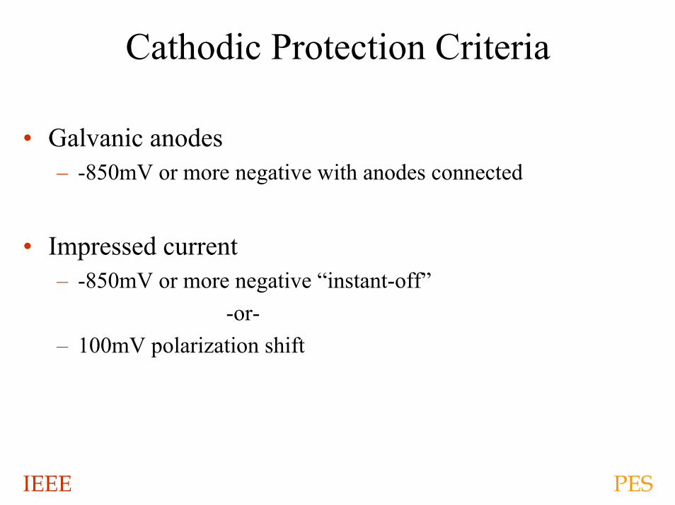
Cathodic Protection Criteria
• Galvanic anodes– -850mV or more negative with anodes connected
• Impressed current– -850mV or more negative “instant-off”
-or-– 100mV polarization shift
IEEE PES
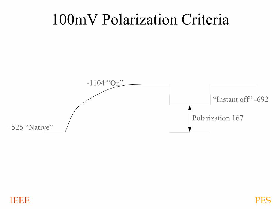
100mV Polarization Criteria
-525 “Native”
-1104 “On”
Polarization 167
“Instant off” -692
IEEE PES
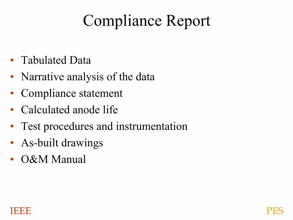
Compliance Report
• Tabulated Data• Narrative analysis of the data• Compliance statement• Calculated anode life• Test procedures and instrumentation• As-built drawings• O&M Manual
IEEE PES
O&M Manual
• Test Procedures• Instrument requirements• Qualification requirements• Frequency• Criteria• Trouble shooting• Spare parts• Wiring diagrams
IEEE PES
Conclusions
• Cathodic protection is viable and necessary to preserve power plant structures
• Proper planning and coordination are essential through out the design and construction phases, to ensure cathodic protection systems work properly
• Properly implemented and monitored cathodic protection will extend the service life of storage tanks and yard piping more than 30 years
IEEE PES
Owner Monitoring & Maintenance
• Record rectifier output levels monthly and compare output to target values
• Repair inoperable rectifiers within 30 days• Inspect test stations and dielectric flanges every six (6)
months for damage and removal• Instruct maintenance staff to replace and test removed
dielectric gaskets• Annually, obtain potential measurements and ensure
effective cathodic protection levels