catia for design and engineering - sdc · pdf filesdc schroff development corporation ...
TRANSCRIPT
SDC
Schroff Development Corporation
www.schroff.com
www.schroff-europe.com
PUBLICATIONS
CATIA for Design and Engineering Version 5 Releases 14 & 15
David S. Kelley Central Michigan University
Copyrighted Material
Copyrighted
Material
Copyrighted Material
Copyrighted
Material
1TUTORIAL
Extruded Features
1
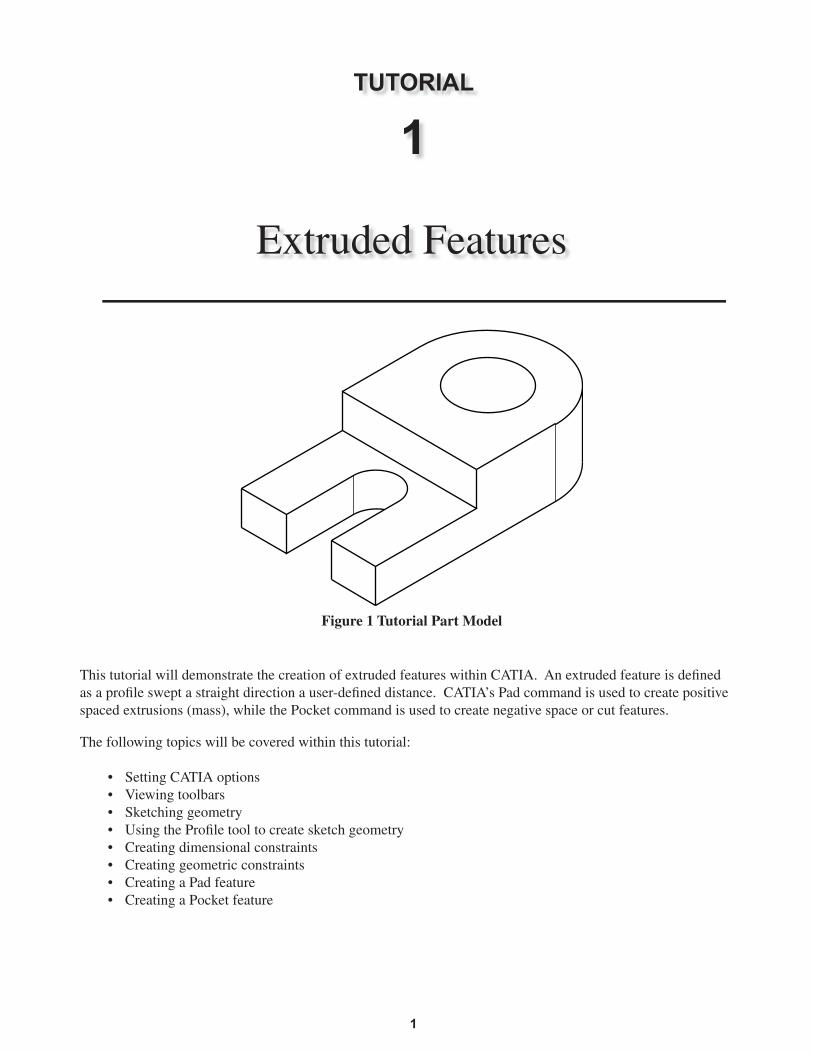
This tutorial will demonstrate the creation of extruded features within CATIA. An extruded feature is defi ned as a profi le swept a straight direction a user-defi ned distance. CATIA’s Pad command is used to create positive spaced extrusions (mass), while the Pocket command is used to create negative space or cut features.
The following topics will be covered within this tutorial:
• Setting CATIA options• Viewing toolbars• Sketching geometry• Using the Profi le tool to create sketch geometry• Creating dimensional constraints• Creating geometric constraints• Creating a Pad feature• Creating a Pocket feature
Figure 1 Tutorial Part Model
Copyrighted Material
Copyrighted
Material
Copyrighted Material
Copyrighted
Material
TUTORIAL 1 • CREATING EXTRUDED FEATURES2
1
STARTING CATIA AND SETTING OPTIONS
The fi rst section of this tutorial will show steps for starting a new part fi le, setting modeling units, and viewing toolbars.
Step 1: Start CATIA
Step 2: Select FILE >> NEW (or select the New icon on the toolbar)
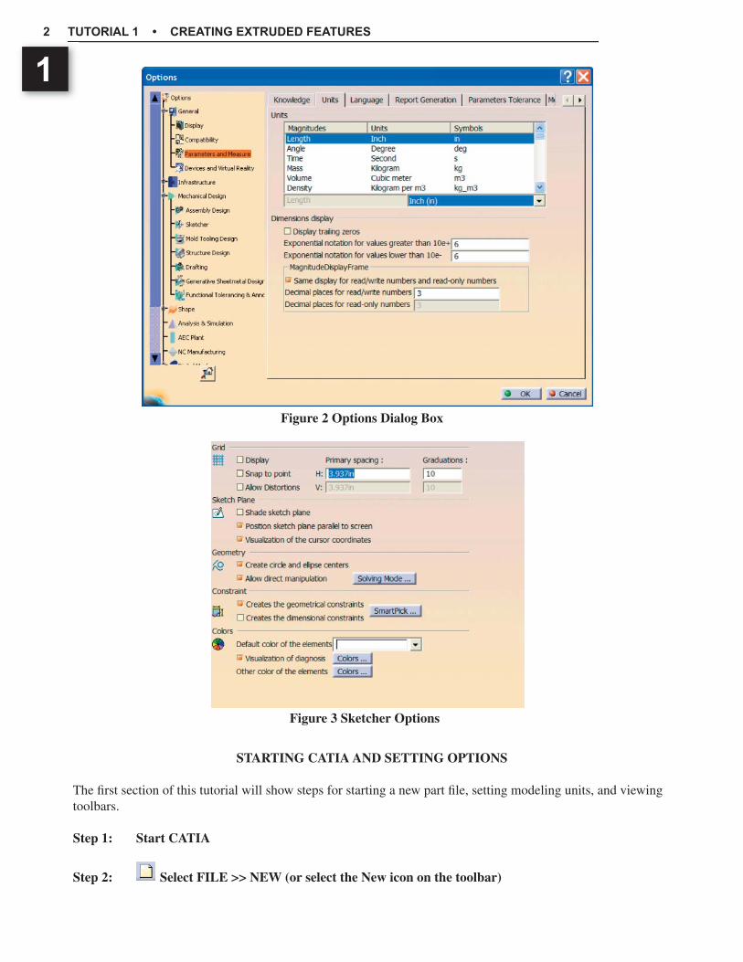
Figure 2 Options Dialog Box
Figure 3 Sketcher Options
Copyrighted Material
Copyrighted
Material
Copyrighted Material
Copyrighted
Material
CREATING EXTRUDED FEATURES 3
1Step 3: Select PART on the New dialog box’s list of available work benches then pick OK
NOTE: If you receive an addtional New Part dialog box, check the Do not show this dialog at startup option then select OK.
Step 4: Select TOOLS >> OPTIONS on the menu bar to open the Options dialog box
The Options dialog box is used to customize a variety of CATIA’s workbench options.
Step 5: Under GENERAL, select the PARAMETERS AND MEASURE option (Figure 2)
Step 6: Select the Units tab then set your unit’s length value to inch(in) (Figure 2)
Step 7: On the Options dialog box under MECHANICAL DESIGN, select SKETCHER
Step 8: Under the Sketcher tab, ensure that the Grid options Display and Snap-To-Point are NOT selected (Figure 3)
Step 9: Ensure that the Constraint option Creates the Geometric Constraints is selected.
Step 10: Select OK on the Options dialog box
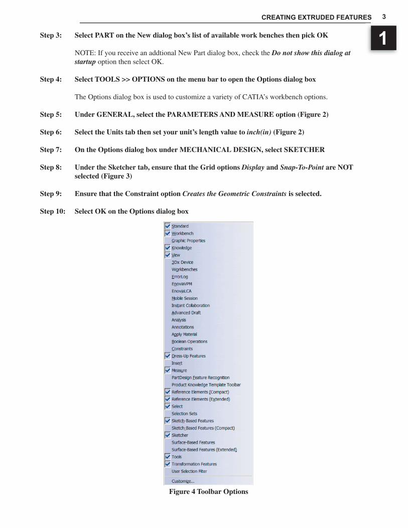
Figure 4 Toolbar Options
Copyrighted Material
Copyrighted
Material
Copyrighted Material
Copyrighted
Material
TUTORIAL 1 • CREATING EXTRUDED FEATURES4
1 PART DESIGN WORKBENCH TOOLBAR OPTIONS
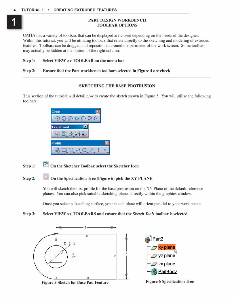
CATIA has a variety of toolbars that can be displayed are closed depending on the needs of the designer. Within this tutorial, you will be utilizing toolbars that relate directly to the sketching and modeling of extruded features. Toolbars can be dragged and repositioned around the perimeter of the work screen. Some toolbars may actually be hidden at the bottom of the right column.
Step 1: Select VIEW >> TOOLBAR on the menu bar
Step 2: Ensure that the Part workbench toolbars selected in Figure 4 are check
SKETCHING THE BASE PROTRUSION
This section of the tutorial will detail how to create the sketch shown in Figure 5. You will utilize the following toolbars:
Step 1: On the Sketcher Toolbar, select the Sketcher Icon
Step 2: On the Specifi cation Tree (Figure 6) pick the XY PLANE
You will sketch the fi rst profi le for the base protrusion on the XY Plane of the default reference planes. You can also pick suitable sketching planes directly within the graphics window.
Once you select a sketching surface, your sketch plane will orient parallel to your work screen.
Step 3: Select VIEW >> TOOLBARS and ensure that the Sketch Tools toolbar is selected
3
4
D 1.5
H
H
H
V
Figure 6 Specifi cation TreeFigure 5 Sketch for Base Pad Feature
Copyrighted Material
Copyrighted
Material
Copyrighted Material
Copyrighted
Material
CREATING EXTRUDED FEATURES 5
1
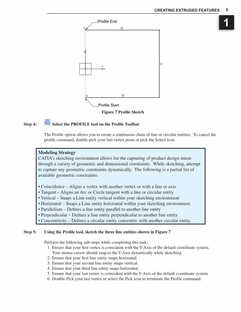
Step 4: Select the PROFILE tool on the Profi le Toolbar
The Profi le option allows you to create a continuous chain of line or circular entities. To cancel the profi le command, double-pick your last vertex point or pick the Select icon.
Modeling StrategyCATIA’s sketching environment allows for the capturing of product design intent through a variety of geometric and dimensional constraints. While sketching, attempt to capture any geometric constraints dynamically. The following is a partial list of available geometric constraints:
• Coincidence – Aligns a vertex with another vertex or with a line or axis• Tangent – Aligns an Arc or Circle tangent with a line or circular entity• Vertical – Snaps a Line entity vertical within your sketching environment• Horizontal – Snaps a Line entity horizontal within your sketching environment• Parallelism – Defi nes a line entity parallel to another line entity• Perpendicular – Defi nes a line entity perpendicular to another line entity• Concentricity – Defi nes a circular entity concentric with another circular entity.
Step 5: Using the Profi le tool, sketch the three line entities shown in Figure 7
Perform the following sub-steps while completing this task:1. Ensure that your fi rst vertex is coincident with the Y-Axis of the default coordinate system.
Your mouse cursor should snap to the Y-Axis dynamically while sketching.2. Ensure that your fi rst line entity snaps horizontal.3. Ensure that your second line entity snaps vertical.4. Ensure that your third line entity snaps horizontal.5. Ensure that your last vertex is coincident with the Y-Axis of the default coordinate system.6. Double-Pick your last vertex or select the Pick icon to terminate the Profi le command.
Figure 7 Profi le Sketch
H
V
H
H
V
Profile End
Profile Start
Copyrighted Material
Copyrighted
Material
Copyrighted Material
Copyrighted
Material
TUTORIAL 1 • CREATING EXTRUDED FEATURES6
1
Modeling Strategy If you don’t capture the geometric constraints as defi ned in Step 5, you can explicitly create geometric constraints with the Constraints Defi nition dialog box option. Using your Control-Key, pre-select any required geometry entities (e.g. Axis, Lines, Verti-ces, Center-Point, etc) then select the Constraints Defi ned in Dialog Box option on the Constraints toolbar. Valid geometric constraints will be available for defi nition.
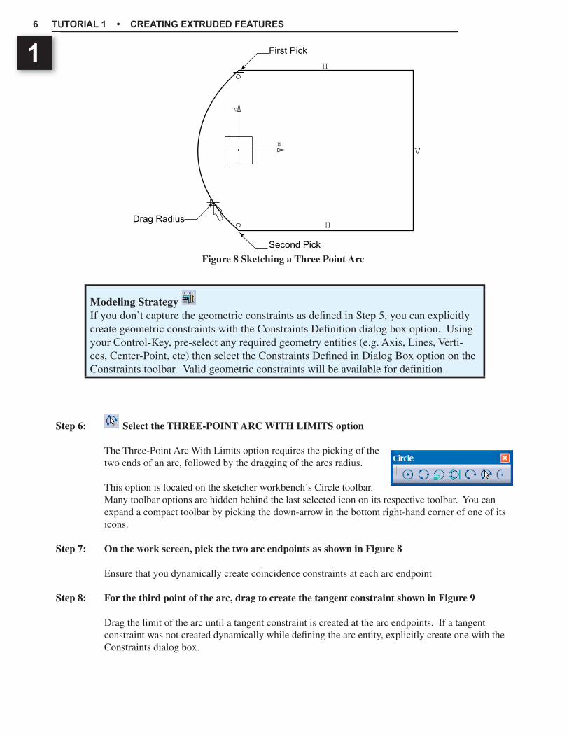
Step 6: Select the THREE-POINT ARC WITH LIMITS option
The Three-Point Arc With Limits option requires the picking of the two ends of an arc, followed by the dragging of the arcs radius.
This option is located on the sketcher workbench’s Circle toolbar. Many toolbar options are hidden behind the last selected icon on its respective toolbar. You can expand a compact toolbar by picking the down-arrow in the bottom right-hand corner of one of its icons.
Step 7: On the work screen, pick the two arc endpoints as shown in Figure 8
Ensure that you dynamically create coincidence constraints at each arc endpoint
Step 8: For the third point of the arc, drag to create the tangent constraint shown in Figure 9
Drag the limit of the arc until a tangent constraint is created at the arc endpoints. If a tangent constraint was not created dynamically while defi ning the arc entity, explicitly create one with the Constraints dialog box.
H
H
V
First Pick
H
V
Second Pick
Drag Radius
Figure 8 Sketching a Three Point Arc

Copyrighted Material
Copyrighted
Material
Copyrighted Material
Copyrighted
Material
CREATING EXTRUDED FEATURES 7
1
Figure 9 Tangent Constraint
Figure 10 Line Dimensional Constraints
H
H
V
Tangent Constraint
H
V
H
H
VH
V
2.493
X
Pick Entity To Dimension
Figure 11 Linear Distance Dimension
H
H
VH
V
2.493
X
Pick Line Entity
2.719
X
Pick Vertical Axis
Copyrighted Material
Copyrighted
Material
Copyrighted Material
Copyrighted
Material
TUTORIAL 1 • CREATING EXTRUDED FEATURES8
1 Step 9: Use the Select tool to pick the line entity shown in Figure 10
Step 10: Select the CONSTRAINT tool
The Constraint tool is used to create dimensional constraints. The fi rst dimension will defi ne the width of the feature. Within this tutorial you will create this dimension by defi ning the length of the selected line. Another option would be defi ning the distance between the two parallel horizontal and vertical lines. Within CATIA’s sketching work bench, any parallel lines picked for dimensioning will create a linear dimension. Any non-parallel lines will create an angular dimension.
Step 11: Place the dimension as shown in Figure 10
Step 12: Create a linear dimensional constraint between the vertical line and V-Axis as shown in Figure 11
Pick the vertical line then pick the V-Axis of the default coordinate system. Place your dimension as shown.
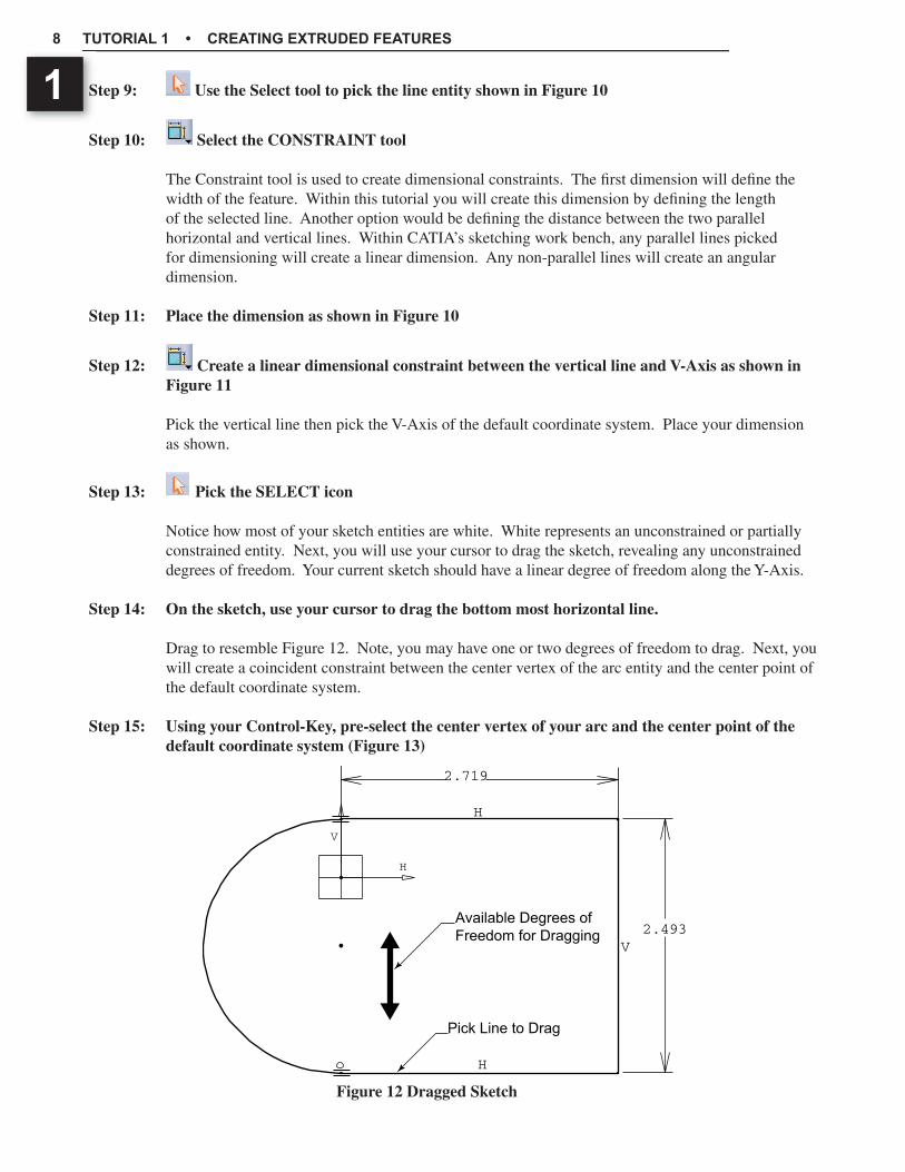
Step 13: Pick the SELECT icon
Notice how most of your sketch entities are white. White represents an unconstrained or partially constrained entity. Next, you will use your cursor to drag the sketch, revealing any unconstrained degrees of freedom. Your current sketch should have a linear degree of freedom along the Y-Axis.
Step 14: On the sketch, use your cursor to drag the bottom most horizontal line.
Drag to resemble Figure 12. Note, you may have one or two degrees of freedom to drag. Next, you will create a coincident constraint between the center vertex of the arc entity and the center point of the default coordinate system.
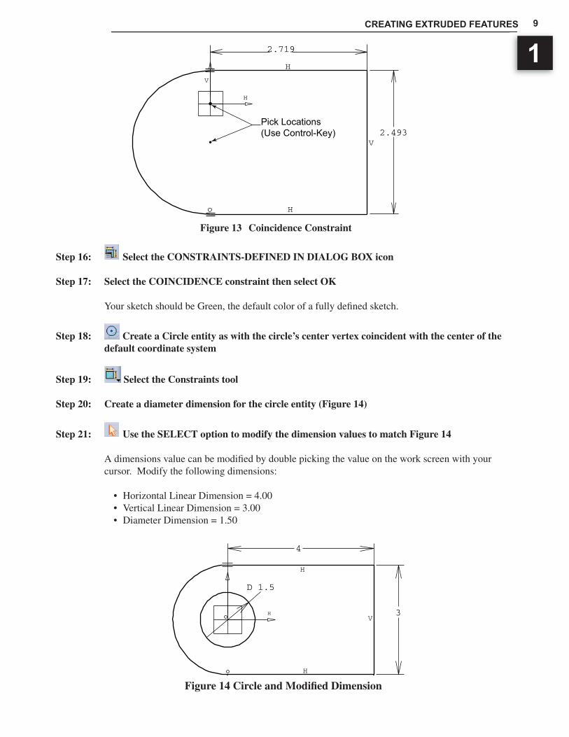
Step 15: Using your Control-Key, pre-select the center vertex of your arc and the center point of the default coordinate system (Figure 13)
Figure 12 Dragged Sketch
H
H
V
H
V
2.493
2.719
Pick Line to Drag
Available Degrees ofFreedom for Dragging
Copyrighted Material
Copyrighted
Material
Copyrighted Material
Copyrighted
Material
CREATING EXTRUDED FEATURES 9
1
Step 16: Select the CONSTRAINTS-DEFINED IN DIALOG BOX icon
Step 17: Select the COINCIDENCE constraint then select OK
Your sketch should be Green, the default color of a fully defi ned sketch.
Step 18: Create a Circle entity as with the circle’s center vertex coincident with the center of the default coordinate system
Step 19: Select the Constraints tool
Step 20: Create a diameter dimension for the circle entity (Figure 14)
Step 21: Use the SELECT option to modify the dimension values to match Figure 14
A dimensions value can be modifi ed by double picking the value on the work screen with your cursor. Modify the following dimensions:
• Horizontal Linear Dimension = 4.00• Vertical Linear Dimension = 3.00• Diameter Dimension = 1.50
Figure 13 Coincidence Constraint
H
H
V
H
V
2.493
2.719
Pick Locations(Use Control-Key)
3
4
D 1.5
H
H
H
V
Figure 14 Circle and Modifi ed Dimension
Copyrighted Material
Copyrighted
Material
Copyrighted Material
Copyrighted
Material
TUTORIAL 1 • CREATING EXTRUDED FEATURES10
1
Step 22: When your sketch is complete, exit the Sketcher workbench
Step 23: Save your part fi le (File >> Save)
CATIA part fi les are given a *.CatPart fi le extension.
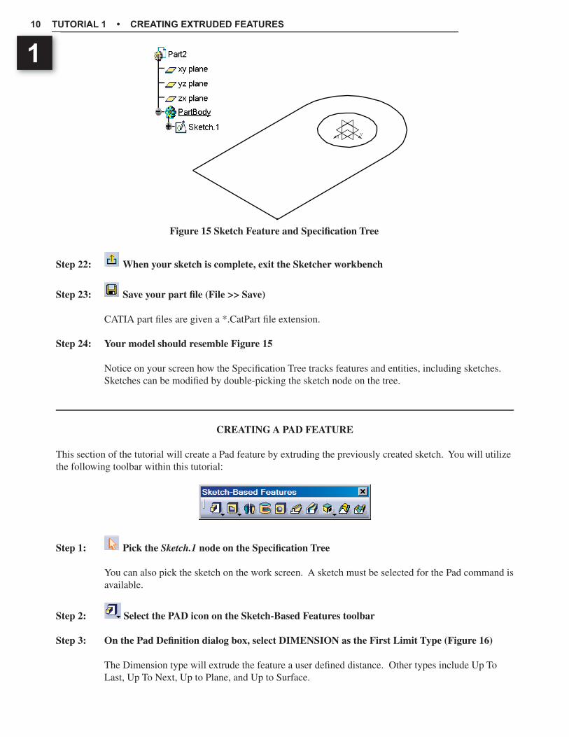
Step 24: Your model should resemble Figure 15
Notice on your screen how the Specifi cation Tree tracks features and entities, including sketches. Sketches can be modifi ed by double-picking the sketch node on the tree.
CREATING A PAD FEATURE
This section of the tutorial will create a Pad feature by extruding the previously created sketch. You will utilize the following toolbar within this tutorial:
Step 1: Pick the Sketch.1 node on the Specifi cation Tree
You can also pick the sketch on the work screen. A sketch must be selected for the Pad command is available.
Step 2: Select the PAD icon on the Sketch-Based Features toolbar
Step 3: On the Pad Defi nition dialog box, select DIMENSION as the First Limit Type (Figure 16)
The Dimension type will extrude the feature a user defi ned distance. Other types include Up To Last, Up To Next, Up to Plane, and Up to Surface.
Figure 15 Sketch Feature and Specifi cation Tree
HV

Copyrighted Material
Copyrighted
Material
Copyrighted Material
Copyrighted
Material
CREATING EXTRUDED FEATURES 11
1
Step 4: Enter 1.50 as the First Limit Length value
On the dialog box, notice that Sketch.1 is listed under the Profi le/Surface Selection box. This is the selected sketch for the extruded pad. If needed, you can edit the sketch by select the Sketch icon.
Step 5: Select the PREVIEW option and observe your model on the work screen.
Step 6: Select OK on the dialog box
Step 7: Save your part
Step 8: Observe the part feature on the Specifi cation Tree
Your model should look similar to Figure 17.
Step 9: Use the following dynamic viewing capabilities to view your model
• Dynamic Pan Middle - Mouse Button• Dynamic Rotation Middle - Mouse Button & Right-Mouse Button• Dynamic Zoom Middle - Mouse Button & Right-Mouse Button, then release Right-Mouse
Button
Modeling Strategy Amongst other capabilities, the Specifi cation Tree is used to track part features. Pan and Zoom viewing options can be used to reposition and resize your tree. Selecting the tree’s primary truck will activate the viewing tools for the tree. Selecting the truck a second time will deactivate focus on the specifi cation tree. The View >> Command List.. >> Swap Tree/View option can also be used to switch the view focus.
Figure 16 Pad Defi nition Dialog Box Figure 17 Pad Feature

Copyrighted Material
Copyrighted
Material
Copyrighted Material
Copyrighted
Material
TUTORIAL 1 • CREATING EXTRUDED FEATURES12
1SKETCHING A POCKET FEATURE
This section of the tutorial will detail how to create the sketch for the fi rst Pocket feature (Figure 18). You will create this sketch on the ZX PLANE. When complete, the next section of this tutorial will have you extrude this sketch with the Pocket tool to create a two directional cut feature.
Step 1: Select the SKETCHER tool
Step 2: As shown in Figure 19, use the Specifi cation Tree to pick the ZX-Plane
The sketch for the pocket feature will be created on the ZX-Plane. In the next section of this tutorial the sketch profi le will be extruded two directions through the extents of the part. You can also pick sketching planes directly on the work screen.
Step 3: Select the PROFILE tool on the Profi le Toolbar
Step 4: Sketch the fi rst line horizontal and the second line vertical (Figure 20)
Locate the ends of the profi le off the existing part as shown in the fi gure. To end the profi le command, double-pick the last endpoint or select the Selection icon.
Step 5: Using the control-key, pre-select the end vertex of the fi rst line and the vertical part edge (Figure 21)
Next, you will create a coincidence constraint between these two entities.
Step 6: Select the CONSTRAINT DEFINITION icon on the Constraint toolbar
Step 7: Select the COINCIDENCE constraint option then select OK
Notice the “O” character adjacent to the line endpoint. This symbol represents a coincidence constraint.
Step 8: Create a Coincidence constraint for the other profi le endpoint and its respective part edge
Step 9: Select the Constraint icon
H
VH
V
2.5
0.75
Figure 19 Sketching Plane SelectionFigure 18 Sketch for Pocket Feature
Copyrighted Material
Copyrighted
Material
Copyrighted Material
Copyrighted
Material
CREATING EXTRUDED FEATURES 13
1
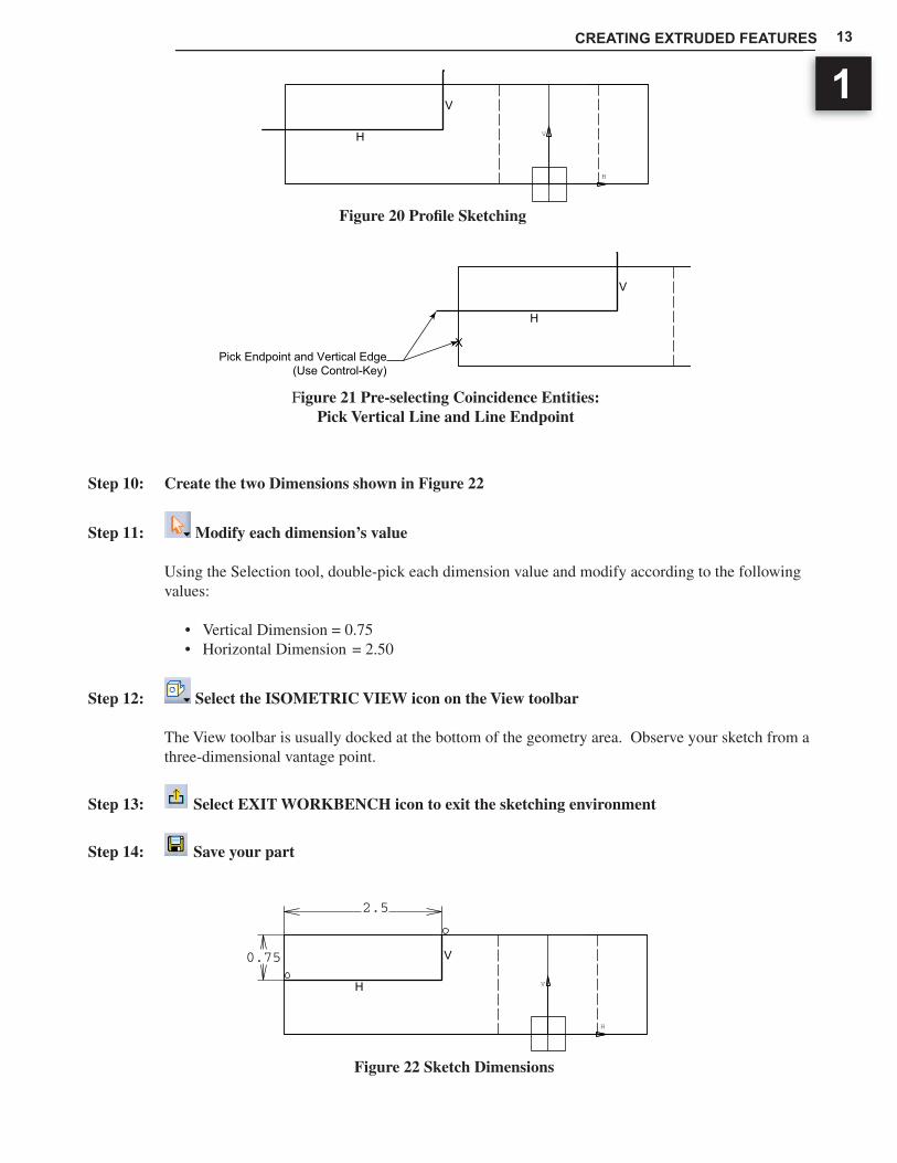
Step 10: Create the two Dimensions shown in Figure 22
Step 11: Modify each dimension’s value
Using the Selection tool, double-pick each dimension value and modify according to the following values:
• Vertical Dimension = 0.75• Horizontal Dimension = 2.50
Step 12: Select the ISOMETRIC VIEW icon on the View toolbar
The View toolbar is usually docked at the bottom of the geometry area. Observe your sketch from a three-dimensional vantage point.
Step 13: Select EXIT WORKBENCH icon to exit the sketching environment
Step 14: Save your part
H
VH
V
H
V
XPick Endpoint and Vertical Edge
(Use Control-Key)
Figure 20 Profi le Sketching
Figure 21 Pre-selecting Coincidence Entities:Pick Vertical Line and Line Endpoint
Figure 22 Sketch Dimensions
H
VH
V
2.5
0.75

Copyrighted Material
Copyrighted
Material
Copyrighted Material
Copyrighted
Material
TUTORIAL 1 • CREATING EXTRUDED FEATURES14
1 CREATING A POCKET FEATURE
This section of the tutorial will create a Pocket feature that is extruded both directions from the sketching plane.
Step 1: On the Specifi cation Tree, pick the last Sketch (Sketch.2)
Note: This sketch may already be selected
Step 2: Select the POCKET tool on the Sketch-Based Features toolbar
Step 3: On the Pocket dialog box, select the MORE option (Figure 23)
By default, a Pocket or Pad feature is extruded in one direction from the sketching plane. The Second Limit group of options on the Pocket defi nition dialog box is used to defi ne a second direction. For this Pocket feature, you will utilize an Up-To-Last Limit Type for both directions.
Step 4: For the First Limit, select the UP-TO-LAST type
The Up-To-Last depth option is similar to the Through All option found in many CAD systems. It will extrude a feature completely through a part.
Step 5: For the Second Limit, select the UP-TO-LAST type
Step 6: On the Pocket Defi nition dialog box, select the SKETCHER icon
You can edit the defi nition of a sketch directly from a Sketch-Based Feature’s dialog box.
Step 7: Modify the horizontal dimension to have a value of 2.25
Step 8: Exit the workbench to return to the Pocket Defi nition dialog box
Step 9: Select OK on the Pocket Defi nition dialog box
Step 10: Save your part
Your part should resemble Figure 24.
Figure 24 Finished FeatureFigure 23 Pocket Defi nition Dialog Box
Copyrighted Material
Copyrighted
Material
Copyrighted Material
Copyrighted
Material
CREATING EXTRUDED FEATURES 15
1
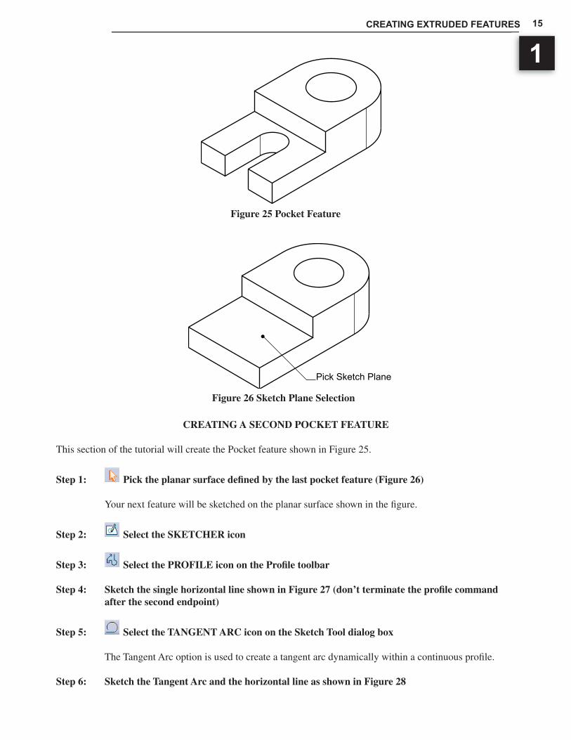
CREATING A SECOND POCKET FEATURE
This section of the tutorial will create the Pocket feature shown in Figure 25.
Step 1: Pick the planar surface defi ned by the last pocket feature (Figure 26)
Your next feature will be sketched on the planar surface shown in the fi gure.
Step 2: Select the SKETCHER icon
Step 3: Select the PROFILE icon on the Profi le toolbar
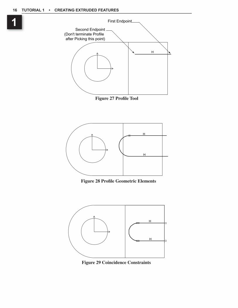
Step 4: Sketch the single horizontal line shown in Figure 27 (don’t terminate the profi le command after the second endpoint)
Step 5: Select the TANGENT ARC icon on the Sketch Tool dialog box
The Tangent Arc option is used to create a tangent arc dynamically within a continuous profi le.
Step 6: Sketch the Tangent Arc and the horizontal line as shown in Figure 28
Figure 25 Pocket Feature
Figure 26 Sketch Plane Selection
Pick Sketch Plane
Copyrighted Material
Copyrighted
Material
Copyrighted Material
Copyrighted
Material
TUTORIAL 1 • CREATING EXTRUDED FEATURES16
1
Figure 27 Profi le Tool
Figure 28 Profi le Geometric Elements
Figure 29 Coincidence Constraints
H
First Endpoint
Second Endpoint(Don't terminate Profile after Picking this point)
H
H
H
H
Copyrighted Material
Copyrighted
Material
Copyrighted Material
Copyrighted
Material
CREATING EXTRUDED FEATURES 17
1
Step 7: Create the two Coincidence constraints shown in Figure 29
Elements to be constrained must be pre-picked before selecteding the Constraints-Defi nition option. Separately, pre-select a line endpoint and its respective part edge. Use the Constraint Defi nition dialog box to create the Coincidence constraint.
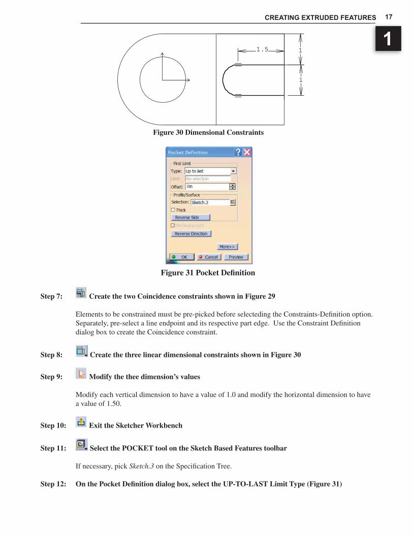
Step 8: Create the three linear dimensional constraints shown in Figure 30
Step 9: Modify the thee dimension’s values
Modify each vertical dimension to have a value of 1.0 and modify the horizontal dimension to have a value of 1.50.
Step 10: Exit the Sketcher Workbench
Step 11: Select the POCKET tool on the Sketch Based Features toolbar
If necessary, pick Sketch.3 on the Specifi cation Tree.
Step 12: On the Pocket Defi nition dialog box, select the UP-TO-LAST Limit Type (Figure 31)
Figure 30 Dimensional Constraints
Figure 31 Pocket Defi nition
1
11.5
Copyrighted Material
Copyrighted
Material
Copyrighted Material
Copyrighted
Material
TUTORIAL 1 • CREATING EXTRUDED FEATURES18
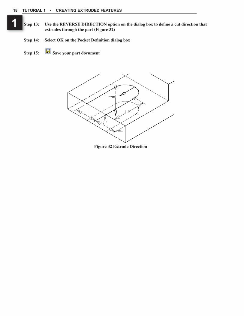
1 Step 13: Use the REVERSE DIRECTION option on the dialog box to defi ne a cut direction that extrudes through the part (Figure 32)
Step 14: Select OK on the Pocket Defi nition dialog box
Step 15: Save your part document
Figure 32 Extrude Direction
01
1
1.5
LIM1LIM1
LIM2LIM2

Copyrighted Material
Copyrighted
Material
Copyrighted Material
Copyrighted
Material
CREATING EXTRUDED FEATURES 19
1
Figure 33 Problem One
Figure 34 Problem Two
MODELING PROBLEMS

Copyrighted Material
Copyrighted
Material
Copyrighted Material
Copyrighted
Material
TUTORIAL 1 • CREATING EXTRUDED FEATURES20
1