ce 4228 data communications and networking transmission techniques
TRANSCRIPT

CE 4228DATA COMMUNICATIONS AND NETWORKINGTransmission Techniques
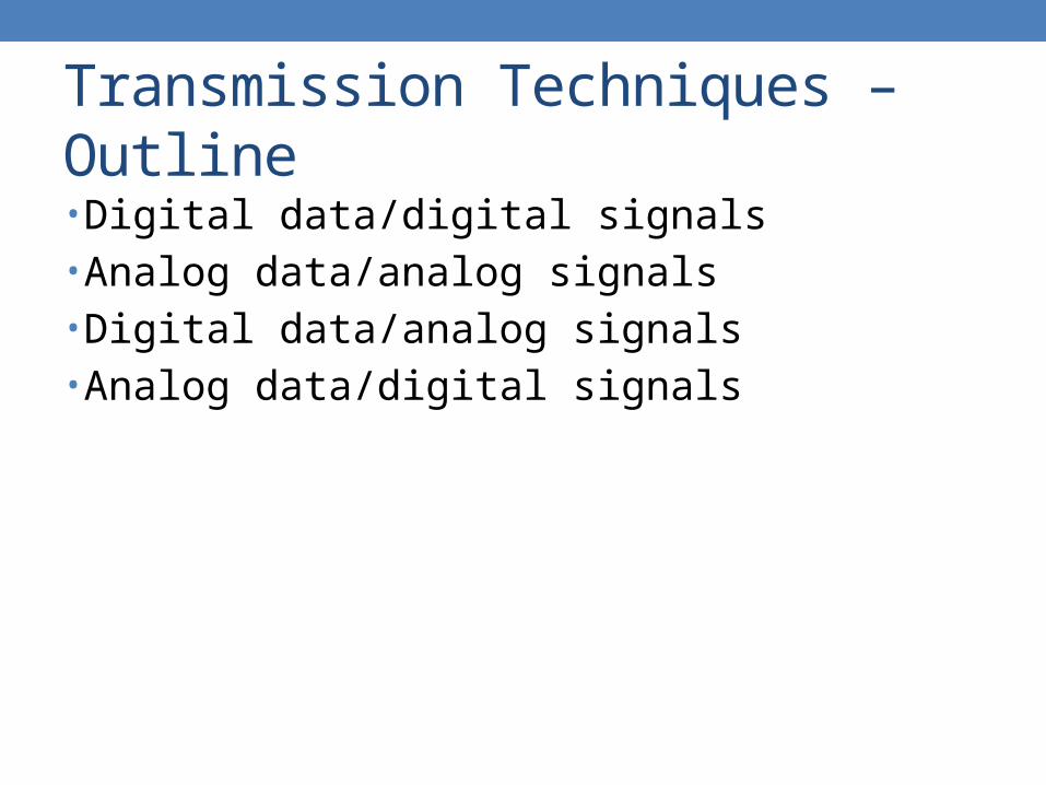
Transmission Techniques – Outline
• Digital data/digital signals• Analog data/analog signals• Digital data/analog signals• Analog data/digital signals

Data and Signals
Data and Signals Analog Signals Digital Signals
Analog Data Baseband/Modulation Codec
Digital Data Modem Encoding

Treatment of Signals
Treatment of Signals Analog Transmissions Digital Transmissions
Analog Signals Amplifiers May use repeaters
Digital Signals Not used Repeaters
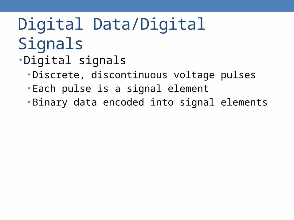
Digital Data/Digital Signals
• Digital signals• Discrete, discontinuous voltage pulses• Each pulse is a signal element• Binary data encoded into signal elements

Coding Schemes – Terminologies
• Unipolar• All signal elements have same sign
• Polar• One logic state represented by positive voltage, the other by
negative voltage
• Data rate• Rate of data transmission in bits per second
• Duration or length of a bit• Time taken for a transmitter to emit a bit

Coding Schemes – Terminologies
• Modulation rate• Rate at which the signal level changes• Measured in baud
• Signal elements per second
• Mark and space• Binary 1 and binary 0 respectively

Coding Schemes – Interpretations
• Need to know• Timing of bits
• When they start and end
• Signal levels
• Factors affecting successful signal interpretations• Signal to noise ratio• Data rate• Bandwidth
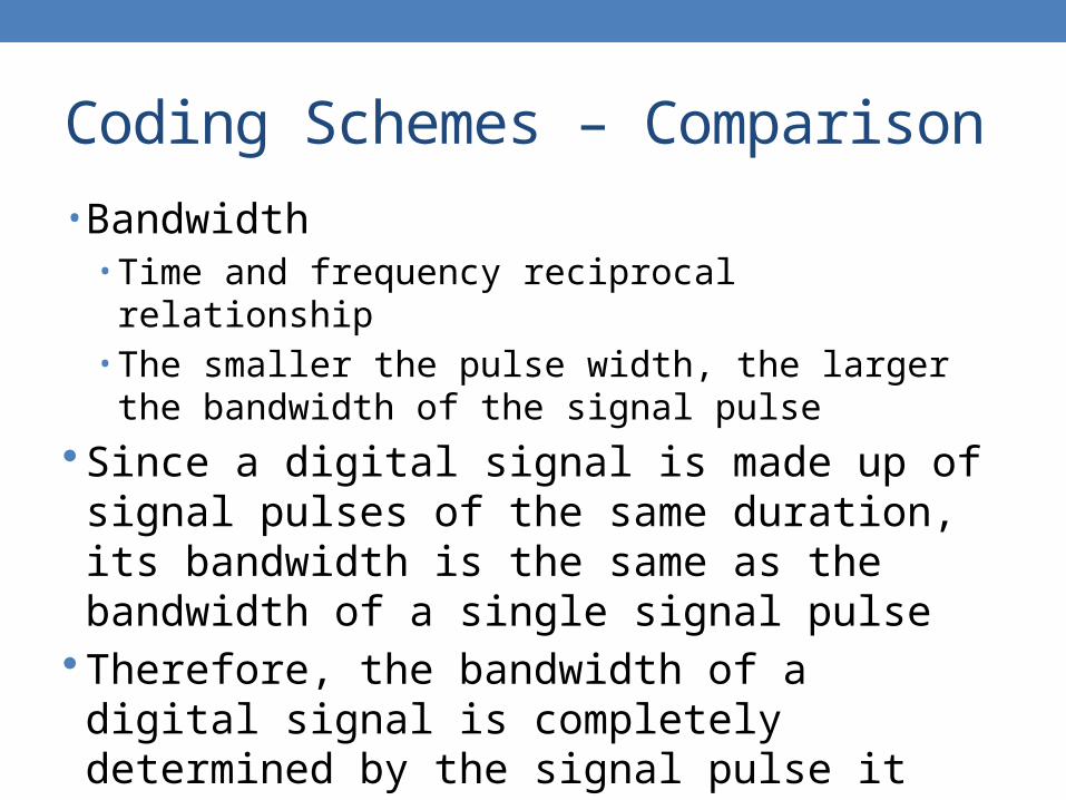
Coding Schemes – Comparison
• Bandwidth• Time and frequency reciprocal relationship• The smaller the pulse width, the larger the bandwidth of the
signal pulse Since a digital signal is made up of signal pulses of the
same duration, its bandwidth is the same as the bandwidth of a single signal pulse
Therefore, the bandwidth of a digital signal is completely determined by the signal pulse it uses• The pulse width and pulse shape

Coding Schemes – Comparison
• Signal spectrum• Lack of high frequencies reduces required bandwidth• Lack of DC component allows AC coupling via transformer,
providing isolation• Concentrate power in the middle of the bandwidth
• Clocking• Synchronizing transmitters and receivers• External clock• Sync mechanism based on signals

Coding Schemes – Comparison
• Error detection• Can be built into signal encoding
• Signal interference and noise immunity• Some codes are better than others
• Cost and complexity• Higher signal rate leads to higher costs• Some codes require signal rate greater than data rate

Coding Schemes
• Unipolar• NRZ-L
• Non-return-to-zero level
• NRZI• Non-return-to-zero inverted
• Biphase• Manchester• Differential Manchester
• Multilevel binary• Bipolar-AMI• Pseudoternary
• Scrambling• B8ZS• HDB3

Coding Schemes – NRZ-L
• Non-return-to-zero level • Two different voltages represent 0 and 1• Voltage constant during bit interval
• No transition, no return to zero voltage• Absence of voltage for zero, constant positive voltage for one
• More often, negative voltage for one value and positive for the other

Coding Schemes – NRZI
• Non-return-to-zero inverted• Invert on ones
• Constant voltage pulse for duration of bit• Data encoded as presence or absence of signal
transition at beginning of bit time• Transition, from low to high or high to low, denotes a
binary 1• No transition denotes binary 0• An example of differential encoding

Coding Schemes – Differential
• Data represented by changes rather than levels• More reliable detection of transition rather than level• In complex transmission layouts, it is easy to lose
sense of polarity

Coding Schemes – NRZ

Coding Schemes – NRZ
• Pros• Easy to engineer• Make good use of bandwidth
• Cons• DC component• Lack of synchronization capability
• Used for magnetic recording• Not often used for signal transmissions

Coding Schemes – Bipolar-AMI
• Bipolar alternate mark inversion• Multilevel binary
• Use more than two levels
• Zero represented by no line signal• One represented by positive or negative pulse
• One pulses alternate in polarity• No loss of sync if a long string of ones
• Zeros still a problem
• No net DC component• Lower bandwidth• Easy error detection

Coding Schemes – Pseudoternary
• Multilevel binary• One represented by absence of line signal• Zero represented by alternating positive and negative• No advantage or disadvantage over bipolar-AMI

Coding Schemes – Bipolar
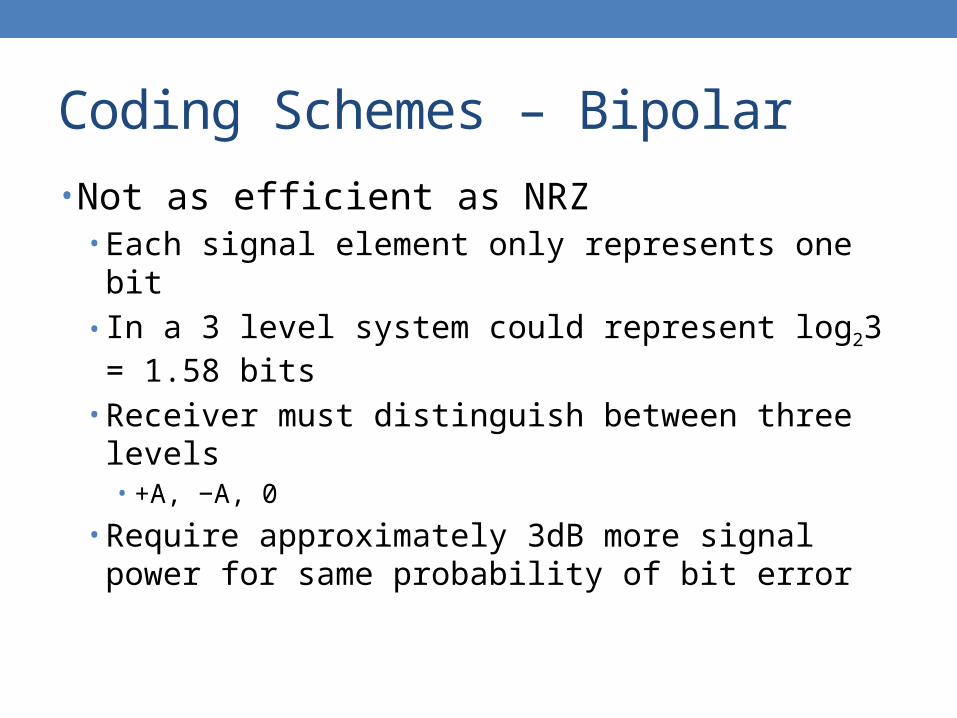
Coding Schemes – Bipolar
• Not as efficient as NRZ• Each signal element only represents one bit• In a 3 level system could represent log23 = 1.58 bits
• Receiver must distinguish between three levels• +A, −A, 0
• Require approximately 3dB more signal power for same probability of bit error

Coding Schemes – Manchester
• Biphase• Transition in middle of each bit period• Transition serves as clock and data• Low to high represents one• High to low represents zero• Used by IEEE 802.3

Coding Schemes – Manchester

Coding Schemes – Diff Manchester
• Differential Manchester• Mid-bit transition is clocking only• Transition at start of a bit period represents zero• No transition at start of a bit period represents one• Differential encoding scheme• Used by IEEE 802.5

Coding Schemes – Diff Manchester

Coding Schemes – Biphase
• Cons• At least one transition per bit time and possibly two• Maximum modulation rate is twice of NRZ• Require more bandwidth
• Pros• Synchronization on mid-bit transition
• Self clocking
• No DC component• Error detection
• Absence of expected transition

Coding Schemes – Modulation Rate
Coding Schemes – Scrambling
• Use scrambling to replace sequences that would produce constant voltage
• Filling sequence • Must produce enough transitions to sync• Must be recognized by receiver and replaced with original• Same length as original
• No DC component• No long sequences of zero level line signal• No reduction in data rate• Error detection capability

Coding Schemes – B8ZS
• Bipolar with 8 zeros substitution• Based on bipolar-AMI• If octet of all zeros and last voltage pulse preceding
was positive encode as 000+−0−+• If octet of all zeros and last voltage pulse preceding
was negative encode as 000−+0+−• Cause two violations of AMI code
• Unlikely to occur by noise
• Receiver detects and interprets as octet of all zeros

Coding Schemes – HDB3
• High density bipolar 3 zeros• Based on bipolar-AMI• String of four zeros replaced with one or two pulses

Coding Schemes – Scrambling

Coding Schemes – Spectral Density

Coding Schemes – Summary

Analog Data/Analog Signal
• Baseband or modulation• Analog signals may need modulation
• Higher frequency could be transmitted more efficiently• Permit frequency division multiplexing• Spectrum relocation
• Types of modulation• Amplitude• Frequency• Phase

Modulation – AM
• Amplitude modulation
• DC component added at baseband to prevent loss of information
• Modulation index nA < 1
• x(t) ≤ 1 → nAx(t) = m(t)
• Bandwidth = 2B• B = bandwidth of m(t)
• DSB, SSB, VSB
1 cos 2A Cs t n x t f t

Modulation – PM/FM
• Angle modulation
• φ(t) = nPm(t) for PM
• φ'(t) = nFm(t) for FM
• Carson’s rule• Bandwidth = 2(β+1)B• FM typical bandwidth ≈ 14B
• Less susceptible to noise
cos 2C Cs t A f t t

Modulation

Digital Data/Analog Signal
• Wireless• Public telephone system
• 300 Hz to 3400 Hz• Use modem
• Amplitude shift keying• Frequency shift keying• Phase shift keying

Modulation

Modulation – ASK
• Amplitude shift keying• Values represented by different amplitudes of carrier
• Presence and absence of carrier is used
• OOK• Susceptible to sudden gain changes• Inefficient• Up to 1200 bps on voice grade lines• Used over optical fiber as IM
cos 2
0CA f t
s t
Modulation – FSK
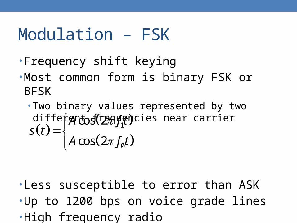
• Frequency shift keying• Most common form is binary FSK or BFSK
• Two binary values represented by two different frequencies near carrier
• Less susceptible to error than ASK• Up to 1200 bps on voice grade lines• High frequency radio• Even higher frequency on LANs using co-ax
1
0
cos 2
cos 2
A f ts t
A f t

Modulation – FSK

Modulation – Multiple FSK
• More than two frequencies used• More bandwidth efficient• More prone to error• Each signaling element represents more than one bit

Modulation – PSK
• Phase shift keying• Phase of carrier signal is shifted to represent data
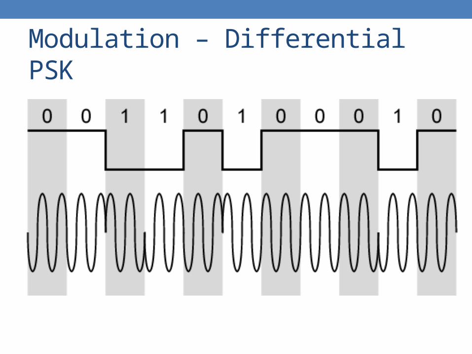
• Binary PSK• Two phases represent two binary digits
• Differential PSK• Phase shifted relative to previous transmission rather than
some reference signal
cos 2 cos 2
cos 2 cos 2
C C
C C
A f t A f ts t
A f t A f t
Modulation – Differential PSK

Modulation – Quadrature PSK
• More efficient use by each signal element representing more than one bit• Shifts of /2 or 90o
• Each element represents two bits
• Offset QPSK• Orthogonal QPSK• Delay in Q stream
cos 24
3cos 2
4
3cos 2
4
cos 24
C
C
C
C
A f t
A f t
s t
A f t
A f t

Modulation – OQPSK Modulator
1 1cos 2 sin 2
2 2C Cs t I t f t Q t f t

Modulation – OQPSK Waveforms

Modulation – Multilevel PSK
• Can use 8 phase angles or more and have more than one amplitude
• Modulation rate D in baud• Data rate R in bps• D = R/log2M
• For 8-ary PSK, 1 symbol represents 3 bits• M = 8• 1 symbol/second = 1 baud = 3 bps

Modulation – QAM
• Quadrature amplitude modulation• Combination of ASK and PSK• Logical extension of QPSK
• Used on asymmetric digital subscriber line or ADSL and some wireless
• Send two different signals simultaneously on same carrier frequency• Use two copies of carrier, one shifted 90°
• Each carrier is ASK modulated• Two independent signals over same medium• Demodulate and combine for original binary output

Modulation – QAM Modulator
1 2cos 2 sin 2C Cs t d t f t d t f t
Modulation – QAM Levels
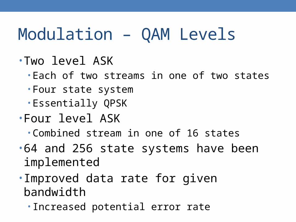
• Two level ASK• Each of two streams in one of two states• Four state system• Essentially QPSK
• Four level ASK• Combined stream in one of 16 states
• 64 and 256 state systems have been implemented• Improved data rate for given bandwidth
• Increased potential error rate

Modulation – Constellations
• Show amplitudes and phases of modulation• Similar to phasor
• ASK• BPSK• QPSK• 8-ary PSK• 16-ary QAM• Minimize BER by maximizing the spacing between
signals points

Modulation – Modems
• V.32• QAM with a 32-point constellation• 4 data bits and 1 parity bit per symbol• 2400 baud• 9600 bps
• V.32 bis• QAM with a 128-point constellation• 6 data bits and 1 parity bit per symbol• 14.4 kbps

Modulation – Modems
• V.34• QAM with a 960-point constellation• 28.8 kbps
• V.34 bis• QAM with a 1664-point constellation• 33.6 kbps
• Shannon limit for the telephone system is about 35 kbps
• V.90 use different technique
Modulation – Coherent Systems
• Coherent systems• Receiver must synchronize the phase of carrier in order to
retrieve data
• Non-coherent systems• Synchronization not required
• Coherent systems are much more costly, but offer much better performance• Lower BER
• ASK and FSK can be either one• PSK and QAM must be coherent since data are carried
by the carrier phase

Modulation – Bandwidth
• BWASK = (1+r)R
• BWFSK= (1+r)R + ΔF
• BWMPSK = (1+r)R/log2M• 0 < r < 1• ΔF = f1 − f0
• ASK and PSK bandwidth directly related to bit rate• FSK bandwidth related to data rate for lower
frequencies, but to offset of modulated frequency from carrier at high frequencies
• In the presence of noise, bit error rate of PSK and QPSK are about 3 dB superior to ASK and FSK

Modulation – Performance
• Comparison of data rate to bandwidth ratio• Bandwidth efficiency

Analog Data/Digital Signal
• Digitization• Conversion of analog data into digital data
• Digital data can then be transmitted using NRZ-L or other codes
• Digital data can also be converted to analog signal
• Analog to digital conversion done using a codec• Pulse code modulation• Delta modulation

Digitization

PCM
• Pulse code modulation• 3 steps
• Sampling• Discretize time
• Quantizing• Discretize value
• Encoding• Digitize value

PCM – Sampling
• Periodical sampling• Taking uniformly spaced samples from an analog signal
waveform
• Intuitively, if the sampling rate is high enough, or T is small enough, the information contained in the analog signal is well represented by its samples
T

PCM – Sampling
• How high is high enough• Sampling theorem
• Nyquist, 1928
• An analog signal of bandwidth B Hz can be completely reconstructed from its samples by filtering if the sampling rate is larger than 2B samples per second• fS > 2B, T < 1/2B
• 2B is called Nyquist rate

PCM – Sampling
• If a signal is sampled at regular intervals at a rate higher than twice the highest signal frequency, the samples contain all the information of the original signal
• Voice data limited to below 4000 Hz• Require 8000 samples per second• Analog samples called PAM
• Pulse amplitude modulation

PCM – Quantizing
• Each sample is assigned to discrete value• Quantizing resembles rounding, which rounds each
sample to pre-specified discrete values dubbed quantum levels
• Number of levels related to number of bits used in encoding
• 8-bit sample gives 256 levels

PCM – Quantizing
• Quantization error or noise• Approximations mean it is impossible to recover the exact
original signal
• The larger the step size, the worse the quantization noise, but the fewer the steps needed to cover a given input range• Bandwidth implications
• Quality comparable with analog transmission

PCM – Quantizing

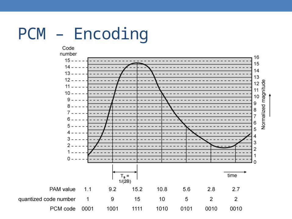
PCM – Encoding
• After being quantized, each sample can take on only a finite number of quantum levels each can be regarded as a logical symbol
• Assign bits for each quantized sample• An encoding scheme is used to translate each of these
symbols to a binary codeword consisting of a number of binary digits
• 8000 samples per second of 8 bits each gives 64 kbps
PCM – Encoding

PCM – D/A Process
• 2 steps• Decoding• Filtering• Quantizing cannot be reversed and thus quantization
noise has to be tolerated

PCM – Performance
• Good voice reproduction • 128 levels PCM
• 7 bits/sample
• Voice bandwidth 4 kHz• Should be 8000 × 7 = 56 kbps for PCM
• Data compression can improve on this• Interframe coding techniques for video
• ADPCM• Adaptive differential PCM• Used in digital TV

PCM – Nonlinear Encoding
• Quantization levels not evenly spaced• Reduce overall signal distortion• Can also be done by companding

PCM – Nonlinear Encoding

PCM – Companding
Compress Channel ExpandInput signal
Output signalSi Sx Sy So
m
CompressorSi
Sx
mChannel
Sy
Sx
ExpanderSy
So

PCM – Companding
• Each of these plots shows output signal strength versus input signal strength• Slope = gain
• The compressor ensures that signal entering the channel within the linear operating range of the channel
• The expander is the inverse function of the compressor and thus restores the original signal strength contrast

PCM – Companding

PCM – Companding Rules
• -law compressor • y = ln(1+ x)/ln(1+)• is degree of compression• Used in North America telephone systems• Soft voices actually get amplified while strong voices are
suppressed
• A-law compressor• y = Ax/(1 + lnA) for 0 x 1/A• y = (1 + lnAx)/(1+ lnA) for 1/A x 1• Used in Europe and followers

Delta Modulation
• Analog input is approximated by a staircase function• Move up or down one level at each sample interval• Binary behavior
• Function moves up or down at each sample interval

Delta Modulation – Example

Delta Modulation – Operation

Transmission Techniques – Conclusion
• Various types of modulation and encoding• Many other variations not discussed
• Understanding the basic properties