ce 4228 data communications and networking data link control
TRANSCRIPT

CE 4228DATA COMMUNICATIONS AND NETWORKINGData Link Control

Data Link Control – Outline
• Transmission timing• Flow control• Channel coding• Error control• HDLC

Interface

Interface
• DTE• Data terminal equipment or data processing devices• Do not usually include data transmission facilities• Need another interface
• DCE• Data circuit terminating equipment • Modem, NIC• Transmit bits on medium
• DCE communicates data and control info with DTE• Done over interchange circuits with interface standards

Interface – Characteristics
• Mechanical• Connection plugs
• Electrical• Voltage, timing, encoding
• Functional• Data, control, timing, grounding
• Procedural• Sequence of events
Digital Transmission Timing
• Timing problems require a mechanism to synchronize the transmitter and receiver
• Two solutions• Asynchronous• Synchronous

Asynchronous
• Data transmitted one character at a time• 5 to 8 bits
• Timing only within each character• Re-synchronized with each character

Asynchronous – Diagram
Asynchronous – Behavior
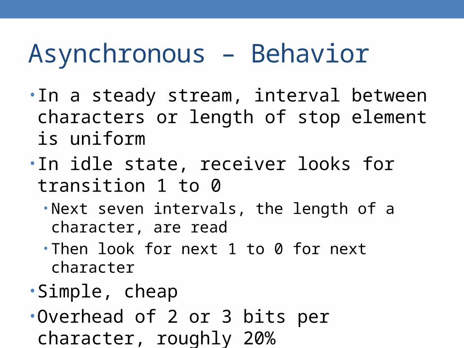
• In a steady stream, interval between characters or length of stop element is uniform
• In idle state, receiver looks for transition 1 to 0• Next seven intervals, the length of a character, are read• Then look for next 1 to 0 for next character
• Simple, cheap• Overhead of 2 or 3 bits per character, roughly 20%• Good for data with large gaps such as keyboard

Synchronous – Bit Level
• Block of data transmitted without start/stop bits• Clocks must be synchronized• Can use separate clock line
• Good over short distances• Subject to impairments
• Embed clock signal in data• Manchester encoding• Carrier frequency for analog transmission

Synchronous – Block Level
• Need to indicate start and end of block• Use preamble and postamble
• Bit patterns to indicate start and end
• More efficient than asynchronous• Lower overhead

Synchronous – Diagram

Frame Transmission

Flow Control
• Ensuring the sending entity does not overwhelm the receiving entity• Preventing buffer overflow
• Transmission time• Time taken to emit all bits into medium
• Propagation time• Time for a bit to traverse the link
• Stop-and-wait• Sliding window
Stop-and-Wait
• Source transmits frame• Destination receives frame and replies with
acknowledgement• Source waits for ACK before sending next frame• Destination can stop flow by not send ACK• Work well for a few large frames• May be necessary for a low quality link
• High error/loss rate

Stop-and-Wait – Fragmentation
• Large block of data may be split into small frames• Limited buffer size• Errors detected sooner when whole frame received• On error, retransmission of smaller frames is needed• Prevent one station occupying medium for long periods
• Stop-and-wait becomes inadequate for multiple smaller frames per message in a high quality link, such as LAN

Stop-and-Wait – Analysis
• T = Tt + Tp + Tr + Tt(ACK) + Tp
(ACK) + Ts
• T = time between two data frame transmissions• Tt = transmission time of data frame = N/R
• Tp = propagation time of data frame = L/c0
• Tr = receiving node processing time
• Tt(ACK) = transmission time of ACK = N(ACK)/R
• Tp(ACK) = propagation time of ACK = Tp
• Ts = sending node processing time
0.1 1 10 100 10000
0.2
0.4
0.6
0.8
1
Stop-and-Wait – Efficiency
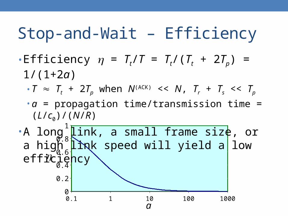
• Efficiency = Tt/T = Tt/(Tt + 2Tp) = 1/(1+2a)• T Tt + 2Tp when N(ACK) << N, Tr + Ts << Tp
• a = propagation time/transmission time = (L/c0)/(N/R)
• A long link, a small frame size, or a high link speed will yield a low efficiency
a

Stop-and-Wait – Example
• Suppose• R = 10 Mbps• L = 2000 meters• c0 = 2 108 m/s
• N = 10000 bits• N(ACK) = 400 bits• Tr = Ts = 2 sec
• T Tt + Tt(ACK) + 2Tp
• 1 + 0.04 + 0.02 msec
• T 1.06 msec
• Efficiency• = 1/1.06 94.3%
• If N =1000 bits• = 0.1/0.16 62.5%
• If R = 100 Mbps• = 0.1/0.128 78.1%
• If R = 1 Gbps• = 0.01/0.034 29.1%

Stop-and-Wait – Link Utilization

Sliding Window Flow Control
• Allow multiple frames to be in transit• Receiver has buffer of size W• Transmitter can send up to W frames without ACK• Each frame is numbered• ACK includes number of next frame expected• Sequence number bounded by field of size k
• Frames are numbered modulo 2k

Sliding Window – Diagram

Sliding Window – Example

Sliding Window – Enhancements
• RNR• Receive not ready• Receiver can acknowledge frames without permitting further
transmission• Must send a normal acknowledge to resume
• If duplex, use piggybacking• If no data to send, use acknowledgement frame• If data but no acknowledgement to send, send last
acknowledgement number again, or have ACK valid flag as in TCP

Sliding Window – Analysis
• Efficiency depends on• Window size W• The value of a
• T = 1 + 2a• Two cases
• Case I• W ≥ 1 + 2a• 1
• Case II• W < 1 + 2a• = W/(1 + 2a)

Sliding Window – W ≥ 1 + 2a
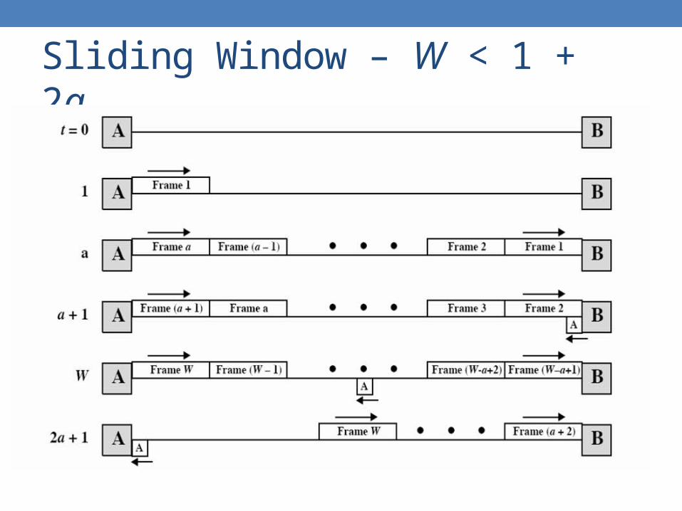
Sliding Window – W < 1 + 2a

Sliding Window – Efficiency

Errors
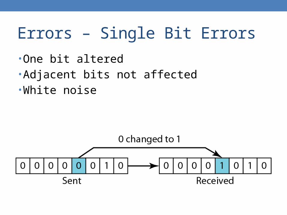
• An error occurs when a bit is altered between transmission and reception
• Caused by thermal noise, electromagnetic interference, loss of synchronization, etc.
• Impossible to guarantee that any single bit will be received correctly, no matter what communication equipment used
Errors – Single Bit Errors
• One bit altered• Adjacent bits not affected• White noise

Errors – Burst Errors
• Contiguous sequence of B bits in which first last and any number of intermediate bits in error
• Impulse noise, or fading in wireless• Effect greater at higher data rates

Channel Coding
• BER is a performance metric of a digital communication system
• Channel coding• Coding for channel error reduction• A process by which redundant digits are inserted into the
source data in such a fashion that the transmitted data exhibit certain patterns which can be used by the receiver to do error detection or error correction
• Block coding• Convolution coding

Error Detection
• Additional bits added by transmitter for error detection code
• Parity• Value of parity bit is such that character has even or odd
number of ones• Even parity or odd parity
• Even number of bit errors goes undetected

Error Detection – Process

Error Detection – Parity

Error Detection – CRC
• Cyclic redundancy check• Cyclical shifting of a valid code produces another valid code
• For a block of k-bit data, transmitter generates n-bit codeword• Exactly divisible by some number
• Receiver divides frame by that number• If no remainder, assume no error
• Capable of detecting various error patterns including most error bursts

Error Detection – CRC Example

Error Detection – CRC Process

Error Detection – CRC Division

Error Detection – CRC Division

Error Detection – CRC Hardware
• Shift register1 0 1 1

Error Detection – CRC Hardware

Error Detection – CRC Polynomial
• Bit pattern can be represented as a polynomial

Error Detection – CRC Polynomial
• Bit pattern can be represented as a polynomial• Simpler analysis

Error Detection – CRC Standard
• CRC-1• Parity bit
• CRC-16• 16 bits per data frame• x16 + x12 + x5 + 1• Also called CRC-CCITT, used in HDLC FCS, Bluetooth
• CRC-32• 32 bits per data frame• x32 + x26 + x23 + x22 + x16 + x12 + x11 + x10 + x8 + x7 + x5 +x4 + x2
+ x + 1• IEEE MAC frame
Error – Treatment
• Correction of detected errors usually requires data block to be retransmitted
• Not appropriate for wireless applications• Bit error rate is high
• Lots of retransmissions
• Propagation delay can be long compared with frame transmission time• Satellite• Would result in retransmission of frame in error plus many subsequent
frames
• Need to correct errors on basis of bits received

Error Correction
• Each k bit block mapped to an n bit block, n>k• Forward error correction encoder
• Codeword sent• Received bit string may contain errors• Received code word passed to FEC decoder
• If no errors, original data block output• Some error patterns can be detected and corrected• Some error patterns can be detected but not corrected• Some rare error patterns are not detected
• Result in incorrect data output from FEC

Error Correction – Process

Error Correction – Operation
• Add redundancy to transmitted message• Can deduce original in face of certain level of error
rate• Block error correction code
• In general, add n−k bits to end of block• Gives n bit block, called codeword• All of original k bits included in codeword
• Some FEC map k bit input onto n bit codeword such that original k bits do not appear

Error Correction – Hamming Code
• 2n−k = n +1• Single bit error 0100110101101111
0100 1101 0110 1111
1 0 0 11 1 1 10 0 1 1
0100110 1101010 0110011 1111111
0100110 1001010 0110011 1110111
Error at 1,2, or 3
Error at 1,2, or 4No error at 1,3, and 4
Error at 2
11010100 0110 1111

Error Correction – Hamming Code

Error Correction – Hamming Code
• Burst error correction by interleaving

Channel Coding – Performance
• Redundant digit insertion leads to either increased bit rate and bandwidth requirement or reduced information rate for fixed bandwidth
• Percentage of errors that can be detected or corrected represents the performance of a channel code• In general, channel coding results in a drastically reduced
BER
• Trade-off between bandwidth and BER

Channel Coding – Performance

Channel Coding Theorem
• Shannon’s 2nd theorem• For R C, there exists a channel coding scheme such
that the information from the data source can be transmitted over the channel with an arbitrarily small error rate despite the presence of noise• Channel capacity C bps• Data source with information rate R bps• If R > C, this cannot be true
Channel Coding Theorem
• No matter how small the BER is specified, a channel code can be designed to beat it• With codec complexity and delay as tradeoff• Reliable communication concept
• It guarantees the existence of an elegant coding method which supports the benefit of channel coding
• It does not offer a means of constructing it

Error Control
• Detection and correction of errors• Lost frames• Damaged frames• Automatic repeat request
• Error detection• Positive acknowledgment• Retransmission after timeout• Negative acknowledgement and retransmission

ARQ
• Automatic repeat request• Stop-and-wait• Go-back-N• Selective reject

Stop-and-Wait
• Source transmits single frame• Wait for ACK• If received frame damaged, discard it
• Transmitter has timeout• If no ACK within timeout, retransmit
• If ACK damaged, transmitter will not recognize it• Transmitter will retransmit• Receiver gets two copies of the same frame• Use ACK0 and ACK1

Stop-and-Wait
• Simple• Inefficient

Stop-and-Wait – Analysis
• 1/(1+2a)• Stop-and-wait flow control• Not account for retransmissions that due to errors
• q = probability of retransmission of erroneous frame• nr = average number of transmissions for each
successful frame• nr = 1×(1−q) + 2×q(1−q) + 3×q2(1−q) + …
• nr = 1/(1−q)
• 1/[nr(1+2a)] = (1−q)/(1+2a)• With retransmissions

Go-Back-N
• Based on sliding window• If no error, ACK as usual with next frame expected• Use window to control number of outstanding frames• If error, reply with rejection
• Discard that frame and all future frames until error frame received correctly
• Transmitter must go back and retransmit that frame and all subsequent frames

Go-Back-N – Damaged Frame
• Receiver detects error in frame i• Receiver sends rejection-i• Transmitter gets rejection-i• Transmitter retransmits frame i and all subsequent

Go-Back-N – Lost Frame
• Frame i lost• Transmitter sends i+1• Receiver gets frame i+1 out of sequence• Receiver sends rejection-i• Transmitter goes back to frame i and retransmits

Go-Back-N – Lost Last Frame
• Frame i lost and no additional frame sent• Receiver gets nothing and returns neither
acknowledgement nor rejection• Transmitter times out and sends acknowledgement
frame with P bit set to 1• Receiver interprets this as command which it
acknowledges with the number of the next frame it expects, which is frame i
• Transmitter then retransmits frame i• Same scenario as in case of damaged rejection

Go-Back-N – Damaged ACK
• Receiver gets frame i and send acknowledgement i+1 which is lost
• Acknowledgements are cumulative, so next acknowledgement i+n may arrive before transmitter times out on frame i
• If transmitter times out, it sends acknowledgement with P bit set as before
• This can be repeated a number of times before a reset procedure is initiated

Go-Back-N

Go-Back-N – Analysis
• p(k) = qk−1(1−q)• Probability that a frame takes k transmissions to succeed• q = probability of retransmission
• nr = average number of transmissions for each successful frame• An erroneous frame causes N retransmissions• N 1 + 2a provided that W 1 + 2a
• W = window size
• At least this many frames have been transmitted when the ACK of the 1st of these frames is supposed to arrive

Go-Back-N – Analysis
• 1/nr (1−q)/(1+2aq)• (1−q)/(1+2a) in case of stop-and-wait
• Benefit of go-back-N decreases when q increases
1
1 1
1 1 1 1 1
1
1
kr
k k
n p k N k q q N k
q Nq
q

Selective Reject
• Also called selective retransmission• Only rejected frames are retransmitted• Subsequent frames are accepted by the
receiver and buffered• Minimize retransmission• Receiver must maintain large enough
buffer• More complex login in transmitter

ARQ – Efficiency

HDLC
• High-level Data Link Control• ISO 33009, ISO 4335
• Bit-oriented protocol• Widely used• Basis for many other important data link control
protocols• Similar formats• Similar mechanisms• LAPB, LAPD, LAPF

HDLC – Station Types
• Primary station• Control operation of link• Frames issued are called commands• Maintain separate logical link to each secondary station
• Secondary station• Under control of primary station• Frames issued called responses
• Combined station• May issue commands and responses

HDLC – Link Configurations
• Unbalanced• One primary and one or more secondary stations• Support full duplex and half duplex
• Balanced• Two combined stations• Support full duplex and half duplex

HDLC – Transfer Modes
• NRM• Normal response mode• Unbalanced configuration• Primary initiates transfer to secondary• Secondary may only transmit data in response to command
from primary• Used on multi-drop lines• Host computer as primary• Terminals as secondary

HDLC – Transfer Modes
• ABM• Asynchronous balanced
mode• Balanced configuration• Either station may initiate
transmission without receiving permission
• No polling overhead• Most widely used
• ARM• Asynchronous response
mode• Unbalanced configuration• Secondary may initiate
transmission without permission form primary
• Primary responsible for line
• Rarely used

HDLC – Frame Structure
• Synchronous transmission• All transmissions in frames• Single frame format for all data and control exchanges

HDLC – Flag Field
• 01111110• Delimit frame at both ends• May close one frame and open another• Receiver hunts for flag sequence to synchronize

HDLC – Bit Stuffing
• Used to avoid confusion with data containing 01111110• 0 inserted after every sequence of five 1s• If receiver detects five 1s it checks next bit• If 0, it is deleted• If 1 and seventh bit is 0, accept as flag• If sixth and seventh bits 1, sender is indicating abort

HDLC – Bit Stuffing Error

HDLC – Address Field
• Identify secondary station that sent or will receive frame
• Usually 8 bits long• May be extended to multiples of 7 bits
• LSB of each octet indicates that it is the last octet or not by 1 or 0
• All ones, 11111111, is broadcast

HDLC – Control Field
• Different for different frame type• Information
• Data to be transmitted to user• Flow and error control piggybacked on information frames
• Supervisory• ARQ when piggyback not used
• Unnumbered• Supplementary link control
• First one or two bits of control filed identify frame type

HDLC – Control Field

HDLC – Poll/Final Bit
• Depend on context• Command frame
• P bit• 1 to solicit, or poll, response from peer
• Response frame• F bit• 1 indicates response to soliciting command
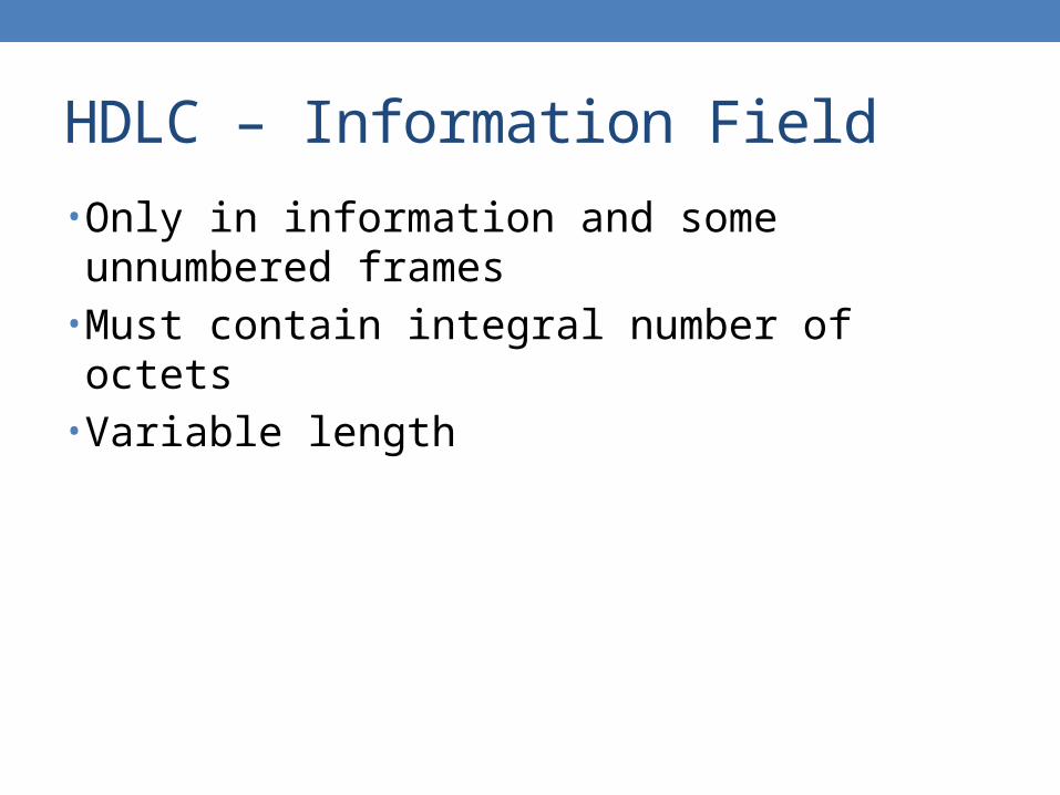
HDLC – Information Field
• Only in information and some unnumbered frames• Must contain integral number of octets• Variable length

HDLC – FCS Field
• Frame check sequence• Error detection• 16-bit CRC• Optional 32-bit CRC

HDLC – Operation
• Exchange of information, supervisory and unnumbered frames
• Three phases• Initialization• Data transfer• Disconnect

HDLC – Operation

HDLC – Operation
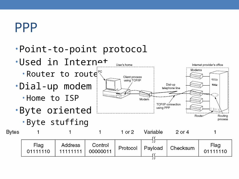
PPP
• Point-to-point protocol• Used in Internet
• Router to router
• Dial-up modem• Home to ISP
• Byte oriented• Byte stuffing

Data Link Control – Conclusion
• Several procedures needed to ensure the data integrity• Additional bits inserted• Different techniques for different kinds of
transmissions• Tasks can be divided