centering a rotary table
TRANSCRIPT

7/27/2019 Centering a Rotary Table
http://slidepdf.com/reader/full/centering-a-rotary-table 1/7
Centering a Rotary Table
Using the Centerline function of a DRO, Version 2
By R. G. Sparber
September 10, 2009
Copyleft1 protects this document.
Before you can use a Rotary Table on a
mill, its center of rotation must bealigned with the spindle's center of
rotation. Many means exist with varying
degrees of ease and accuracy. In most
cases, you start with a rough alignment.
My favorite method is to mount a spud
in the spindle and a modified dead center
in the RT's tapered hole. This can get the
center of rotation of the RT to within
about 0.02” of the center of rotation of
the spindle. For some jobs, this is plenty
good.
But if you want better results, then it is common to fix a Dial Test Indicator onto
the spindle and indicate the pin set in the center of the RT. This works very well
although it can be a bit time consuming if you are trying to get it as close to perfect as
possible.
Now, with a solid DTI support, a good quality DTI, and a bit of patience, you can get
the alignment to within +/-0.0002”. If that is what you need, then stick with the DTI.
But if you can accept an error of +/-0.0005”, then a DRO can be used and it shouldspeed up the process.
I own a DRO which has a centerline function. It finds the halfway point between my
present position and the zero point on a given axis. For example, say I am at the
1 You are free to distribute this article but please, don't remove my name from the byline.
Page 1 of 7
R. G. Sparber September 10, 2009

7/27/2019 Centering a Rotary Table
http://slidepdf.com/reader/full/centering-a-rotary-table 2/7
location X = 2.0000”. I run the centerline function and the display changes to X =
1.0000”. Move to X = 0 and you are at the centerline point. Doesn't sound very
impressive until you start to use it. The following procedure does not need the
centerline function. You just need to be able to read off the mill table's XY position and
be able to divide by 2.
There is one potential problem with using a center pin. The goal is to align the center of rotation of the RT with the spindle, not the pin to the spindle. Are you sure that center
hole is really located correctly? Are you sure it is absolutely free of swarf which can
offset the pin?
The true test of alignment is to focus on the actual rotation of the RT. First lets look at
theory. The center of rotation of the RT is commonly seen as the center of a pin placed
in the tapered center hole as shown above. It is very likely that this is correct but if you
really want to be picky, the center of rotation is a point equal distant from a point on the
RT that has been moved through 360 degrees.
Say I attach a block to the surface of the RT2
and set the angle to 0 degrees. I then define
the block's inner face as X = 0 with an
Electronic Edge Finder connected to my
DRO. I would do this by moving the EEF
from near the center of the RT out to the
block. When the EEF contacts that inner face
of the block, I set my zero for the X axis.
2 I am using a block here because my mill is not large enough to access the perimeter of the RT's table along the Y axis.
Page 2 of 7
R. G. Sparber September 10, 2009

7/27/2019 Centering a Rotary Table
http://slidepdf.com/reader/full/centering-a-rotary-table 3/7
Next I crank the RT until the block is at 180
degrees. If my Y location is exactly at the
center of the RT, then when I touch down on
that same inner face of the block, I will be at a
distance equal to the diameter of the circle
inscribed by the block minus the diameter of the EEF probe. I don't care about either
diameter. But if I now run the centerline
function, I will see how far back to crank the X
axis to end up at the center of rotation of the RT
along the X axis.
There is one potential hitch here. Recall that I had to assume that I was right on the Y
centerline of the RT. That is unlikely, at least for starters. Lets see what happens whenI'm not exactly on the Y centerline.
Here I am moving along a line parallel to the
X axis but with a non-zero Y value. If, and
this is a big if, the block face is perpendicular
to the X axis, then Y misalignment of my line
does not matter. In fact, if the block is 2”
wide, I can be off by 1” and still find the point
on the X axis which is aligned with the RT's
center of rotation.
Page 3 of 7
R. G. Sparber September 10, 2009

7/27/2019 Centering a Rotary Table
http://slidepdf.com/reader/full/centering-a-rotary-table 4/7
In the real world, the block cannot be perfectly
aligned so lets look at an extreme case.
If I am running my EEF through the center of
rotation of the RT, then block misalignment
does not matter. However, it is more likely Iwill not be on this line so consider the case of
being above that line. As I touch down on the
block while at 0 degrees (on the left), I hit the
corner which is closest to the center of the RT.
Then I crank the RT until the block is at 180
degrees. Now I will hit the corner furtherest
away from the center. I end up with a
centerline error that is not zero.
But notice that the
X centerline error I get is much smaller than
the
Y centerline error. If I now repeat this process
along the Y axis, my X axis error will be much
smaller.
I now have a Y axis centerline very close to true.
By repeating the X axis centerline again, I will get
it closer. You can repeat this process as many
times as needed to get to the limits of the DRO's
repeatability and accuracy.
Now, you may be thinking, what a hassle to go
back and forth so many times. That is true. Theanswer is to align the block carefully in the first
place. Then you only need to run one centerline
for each axis.
Page 4 of 7
R. G. Sparber September 10, 2009

7/27/2019 Centering a Rotary Table
http://slidepdf.com/reader/full/centering-a-rotary-table 5/7
Time to visit my shop. My EEF is held in my drill
chuck. In hindsight, I realize this is not a very good
choice because the drill chuck has a Total Indicated
Runout of a few thou. I will switch to a collet for
better accuracy.My center hole is clean so could be used for the
alignment. However, note that the diameter of this
hole is much less than the diameter of the circle to
be inscribed by the block. This means that EEF
alignment is more critical with the center hole. I did
try to do alignment using the cut out in the table but
could not get all of the swarf out.
My block has been intentionally set at an angle in
order to test out my theory. It would not take mucheffort to cut a ridge in the bottom of the block so it
aligns with one of the T slots. I was able to do a
fairly decent alignment job by sighting along one of
the cut circles.
I start out with the EEF roughly centered on the RT.
The tool offset is set to center.
On this alignment run I placed the block by eye so it itsinner face was fairly parallel to the T slot under it. I
also turned the RT so the block was fairly parallel to
the Y axis.
The EEF was then moved to contact the block and the
RT angle noted.
The RT was then turned 180 degrees. My EEF has just
come in contact with the block. The distance traveled
divided by 2 is the center of the RT along the X axis.
Page 5 of 7
R. G. Sparber September 10, 2009
7/27/2019 Centering a Rotary Table
http://slidepdf.com/reader/full/centering-a-rotary-table 6/7
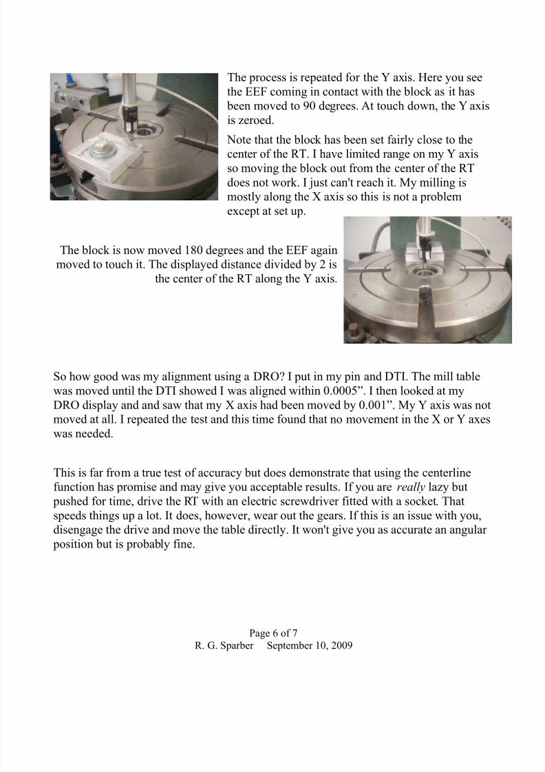
The process is repeated for the Y axis. Here you see
the EEF coming in contact with the block as it has
been moved to 90 degrees. At touch down, the Y axis
is zeroed.
Note that the block has been set fairly close to thecenter of the RT. I have limited range on my Y axis
so moving the block out from the center of the RT
does not work. I just can't reach it. My milling is
mostly along the X axis so this is not a problem
except at set up.
The block is now moved 180 degrees and the EEF again
moved to touch it. The displayed distance divided by 2 isthe center of the RT along the Y axis.
So how good was my alignment using a DRO? I put in my pin and DTI. The mill table
was moved until the DTI showed I was aligned within 0.0005”. I then looked at my
DRO display and and saw that my X axis had been moved by 0.001”. My Y axis was notmoved at all. I repeated the test and this time found that no movement in the X or Y axes
was needed.
This is far from a true test of accuracy but does demonstrate that using the centerline
function has promise and may give you acceptable results. If you are really lazy but
pushed for time, drive the RT with an electric screwdriver fitted with a socket. That
speeds things up a lot. It does, however, wear out the gears. If this is an issue with you,
disengage the drive and move the table directly. It won't give you as accurate an angular
position but is probably fine.
Page 6 of 7
R. G. Sparber September 10, 2009

7/27/2019 Centering a Rotary Table
http://slidepdf.com/reader/full/centering-a-rotary-table 7/7
Acknowledgement
I wish to thank Larry Gill for reviewing this document. Any typos you find now are
from my fiddling after he was done. Thanks to Martin on the Yahoo group Mill_Drill for
improvements to Version 2 of the article.
I welcome your questions and comments. Only through the community can we improve
this article.
Rick Sparber
Page 7 of 7
R. G. Sparber September 10, 2009