challenges on modelling fluid-dynamic problems of · the high design sensitivities for new...
TRANSCRIPT

Longo Jose
Netherlands
ESA, Technical Centre ESTEC
ID : 3125302
Title : Challenges on modelling fluid-dynamic problems of space propulsionsystems. Overview of selected programmatic efforts at the European SpaceAgency
Theme :
Attached documents :Abstract submission-JLongo.pdf
Resume :
Current and expected developments in space transportation have led to growing interest in new solutions for the design ofpropulsion systems. These new solutions require essential improvements over current one in order to ensure economic viabilityand to fulfil mission and safety constraints. The size and complexity of this problem has led to growing importance of numericaltools for design and optimization involving the coupling of many disciplines as well as the optimal use numerical techniques andcomputer resources. The high design sensitivities for new spacecraft and the small payload fractions for launcher vehicles makenecessary new development and test approaches, with numerical multi-disciplinary simulation and optimization as well asexperimental vehicles playing a deciding role.This paper presents the current programmatic efforts at the European Space Agency in order to facilitate the solution of some ofthose issues. The status of the physical modelling and code development issues such as numerical algorithms, grid generationand validation strategies are addressed. The problem to obtain adequate data for code validation is discussed. The strong needto validate the computer codes by comparison with experiments is for high enthalpy flows not an easy task due to the widespectrum of physical conditions to be reproduced in the experiments. Measurement techniques, sensors, ground facilities andin-flight experimentation are addressed and discussed. While viscous, high enthalpy unsteady flows are still restricted to simpleproblems due to a strong demand in computer resources, computational fluid dynamics (CFD) based multidisciplinary analysisis emerging as a key element in aerospace design. Supported by a continuous, almost linear, growth in computer capacity andperformance, this new procedure to conduct design and analysis is paying off. However, the effective use of CFD to morecomplex applications, require more sophisticated algorithms, since one of the key problems here is the treatment of multiplespace and time scales. These arise particularly for combustion problems, where chemically reacting flows, flame fronts,turbulent flows and plasma dynamics need to be simultaneously accounted.The paper addresses a number of selected problems of multidisciplinary character with complex high enthalpy physics liketransient flow problems with cryogenic fuels like sloshing, priming, chilldown; but also problems like buffeting, acoustic, plumeimpingement and contamination.
Powered by TCPDF (www.tcpdf.org)

1
Challenges on modelling fluid-dynamic problems of space propulsion systems at ESA
Overview of selected programmatic efforts (2013-2017)
J.M.A. Longo European Space Agency Space Propulsion 2016 Rome, Italy, May 2 to 6, 2016

2
Background motivation
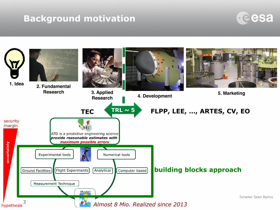
The long term objective of ESA in Aerothermodynamics is to provide tools for a virtual product, here defined as the philosophy of providing a reasonable estimate with maximum possible errors in the predicted performances, to certify the system prior the first flight.
4. Development 3. Applied Research
5. Marketing
1. Idea 2. Fundamental Research
reduce costs by reducing drastically development-risks
3
Background motivation
4. Development 3. Applied Research
5. Marketing
1. Idea 2. Fundamental Research
Almost 8 Mio. Realized since 2013
FLPP, LEE, …, ARTES, CV, EO TEC TRL ~ 5
building blocks approach
4
Contents
• Propellant feedlines • Propellant tanks • Rocket plume • Intake flows

5
Contents
• Propellant feedlines • Propellant tanks • Rocket plume • Intake flows

6
Propellant feedlines Propulsion valve
Velocity magnitude and streamlines along a 2D section of the Cryogenic valve (VKI)
CryoLine vacuum chamber and test section (VKI)
Sapphire window, cryogenic valve and pressure temperature modules (VKI)
Comparison between numerical and experimental results obtained in the cryogenic valve.
Characterization of a cryogenic propulsion valve (TechSpace-Aero, BE): Characteristic relationship between the volumetric flow rate and pressure drop across the valve for liquid nitrogen and water. For the cryogenic tests, temperature measurements at the valve inlet and outlet are also presented, as well as visualizations of the flow upstream the test section. The experimental results show that the valve flow coefficient is identical for both liquid nitrogen and water in normal flow regime. L. Peveroni et al. Experimental and numerical study of the flow characteristics in a cryogenic valve with liquid nitrogen and water. Proceedings of the 8th European symposium on aerothermodynamics for space vehicles, March 2015, Lisbon, Portugal.

7
Propellant feedlines Two-phase flow phenomena
CHIEF general view T amb T cryo
Example of Pipeline chilldown
CHIEF measurement section representative of a real engine cooling channel (VKI)
CHIEF vacuum chamber and measurement section (VKI)
Cryogenic pressure transducer (VKI)
Cryogenic temperature transducer (VKI)
Modelling of chill down two-phase flow phenomena (ET GmbH, DE): Measurement of pressure and temperature during the transient phenomena; high speed visualisation of the liquid two-phase flow; determination of the two phase flow characteristics (bubble velocity, bubble shape,…). Experimental investigation of cryogenic two phase flow. Energie Technologie GmbH (DE), ESA Contract no. 4000111616/14/NL/PA. S. also Session 46 SP2016.
Numerical simulation flow through orifice (NUMECA)

8
Propellant feedlines Cryogenic fluid hammer
Fluid Hammer Facility (VKI) Top: chamber closed; bottom: chamber open.
Piping & Instrumentation Diagram of the Fluid Hammer Facility
Typical pressure surge measured at impact location (transducer P3)
Fluid Hammer Facility (VKI, BE): A dedicated facility representative of the priming process in a satellite propulsion system to create a reliable experimental database. The facility integrates the elements affecting the fluid hammer occurrence, i.e., the pressurized liquid reservoir, the fast opening valve (FOV) and the propellant line with a closed end. These elements are clamped on a vertical rigid structure. J-B. Gouriet et al. Multiphase fluid hammer with non-cryogenic and cryogenic fluids. Proceedings of the 8th European symposium on aerothermodynamics for space vehicles, March 2015, Lisbon, Portugal. S. also Session 46 SP2016.

9
Propellant feedlines Simulation tool
RL-10 start-up: ESPSS(red), TEST(black), NASA(blue). AIAA-2011-6032
European Space Propulsion Simulation System ESPSS (Empresarios Agrupados, ES): a propulsion system library capable of modelling various kinds of dynamic systems: modelling & simulation of spacecraft and rocket propulsion systems; design and Analysis of steady state condition able to reproduce all rocket engine cycles; simulation of all possible transient phases from start-up to shut-down; simulation of in-orbit conditions of spacecraft propulsion systems (including flight dynamic forces as a function of attitude and orbit); simulation of subcomponents interaction like solar arrays, reaction wheels, gravity booms, and tanks. M. Leonardi et al. A zooming approach to investigate heat transfer in liquid rocket engines with ESPSS propulsion simulation tool. Proceedings of the 8th European symposium on aerothermo-dynamics for space vehicles, March 2015, Lisbon, Portugal. S. also Session 69 SP2016 and the Poster exhibition.

10
Contents
• Propellant feedlines • Propellant tanks • Rocket plume • Intake flows

11
Propellant in tanks Physical modelling
Experimental detection of wall angles and free surface topology (VKI)
Experimental detection of thermal stratification using LIF (VKI)
Prediction methods for propellant management devices (NUMECA, BE): Accurate description of propellant phenomena like linear and non-linear sloshing, thermal stratification, ullage pressure variation, liquid settling, chill down and boiling for the development and validation of CFD methods for the design and verification of tanks and the related Propellant Management Devices (PMD) for conventional and cryogenic propellants during all phases of a typical mission of a space vehicle. C. Dinescu et al. A verification an validation approach for eulerian modelling of sloshing flows. Proceedings of the 8th European symposium on aerothermodynamics for space vehicles, March 2015, Lisbon, Portugal. S. also Session 30 SP2016.
Experimental facility for boiling tests(VKI)

12
Characterization of sloshing with cryogenic fuels (DLR, DE): Bubble detection and surface topology measurements using ultrasound tomography; nuclear magnetic resonance tomography; computed X-ray tomography; time-of-flight camera; optical tomography; Electrical tomography; microwave tomography; cavity perturbation method; particle velocimetry; wire-mesh sensors and fibre optic. Advanced measurement techniques for validation of CFD for cryogenic flows in reduced gravity. DLR (DE), ESTEC/Contract no. 4000109332/13/NL/Cbi.
Propellant in tanks Measurement techniques
Fibre optic, ultrasound tomography array and test facility (DLR)
TNO fibre optic test performance at DLR facility

13
Propellant in tanks Diaphragm design
Verification of diaphragm analysis (MT Aerospace, DE): Experimental simulation of membrane tank filling/draining and lateral sloshing. Provide with models to estimate the impact of numerically non-resolved effects as history and scatter on folding and damping properties. Implementation into FSI tools in form of, e.g. adapted uncertainty margins for the numerical prediction. Verification of Diaphragm Analysis. MT Aerospace AG, ESA Contract no. 4000114567/15/NL/KML.
Numerical modelling tool for evaluation of sloshing-reaction control system coupling (NUMA, IR): Design and validation of a ground based experiment to simulate non-linear sloshing phenomena in tanks of spacecraft. Enhanced comprehension of the effects of non-linear slosh dynamics on spacecraft stability by extrapolation of experimental results to flight conditions. Numerical modelling tool for evaluation of sloshing-reaction control system coupling (SI). NUMA Engineering Services Ltd., ESA Contract no. 400011493/14/NL/PA.
Work Logic (MT Aerospace)
Comparison of gyroscopic and fluid motion under spin and linear acceleration (NUMA)

14
Contents
• Propellant feedlines • Propellant tanks • Rocket plume • Intake flows

15
Rocket plume Nozzle flow
Retro-rocket deceleration: Upgrade a rarefied gas facility and its associated measurement techniques to verify the performances of a RCS capable to control and guide an entry probe for Mars landing. Mars Robotic Exploration Program-2. ESA/Prog. Ref. E918-008MP. S. also Poster exhibition SP2016
separation shock
edge of separation bubble
interaction of separation and vehicle bow shock
interaction of bow shock and boundary of separation bubble
vehicle bow shock steepened by separation bubble
boundaries of retro rocket jet
Mach disc
Stage separation: Reconstruction of the complex flowfield that occurs during serial stage separation when the plumes of retro rockets interact with the freestream flow creating asymmetric, unsteady, events on the upper stages. Launcher stage separation and plume interaction validation. DLR (DE), ESA Contract no. 4000102454/10/NL/NA.
Base flow: Characterization of the gas dynamical flow phenomena and their interactions, e.g. compression shocks, shear layers, expansion fans, in the base region of an expendable launcher vehicle by means of experimental data recorded with high-speed PIV measurements and reduced using proper orthogonal decomposition methods. Provide detailed knowledge on the status of CFD methods for rebuilding such type of flows. K. Hannemann et al. Launch vehicle base buffeting-recent experimental and numerical investigations. Proceedings of the 7th European symposium on aerothermodynamics for space vehicles, May 2011, Brugge, Belgium.
Experimental surface and flow visualization (DLR)
POD results (TU Delft) and Numerical simulation (ONERA)

16
Rocket plume Plume-soil interaction
Plume-soil interaction characterization (FGE, UK): Characterization of the thruster exhaust plume in vacuum conditions, by collecting the species distribution and thermodynamic data in the plume at a number of streamwise locations downstream of the nozzle; and by determining the sticking coefficients of the thrusters species on the regolith surface. Phobos sample return. ESA/IPC(2015)135.
Plume and soil testing facility (Uni. Glasgow, UK): a vacuum facility in which it is possible to carry out different measurements on flows with dust particles and fulfil the following detailed objectives: assessment of scaling phenomena, vacuum effects and pulsing of rockets; erosion effect of the plume impingement on the planet surface (airless bodies and Martian conditions); lateral extent and depth of regolith contamination due to rocket plumes; impact of the plume/regolith interaction on the spacecraft (forces and moments); effect of the regolith liberated by the rocket plume impingement on the spacecraft forces and moments and particularly on the engine and engine-nozzle during lunar/planetary landing operations; brown out due to plumes and surface dust. As secondary objective the facility will be capable of allowing small, controlled blasts to initially assess the fragmentation of structures in reduced atmospheres. Effect of a regolith liberated by a rocket plume impingement. FGE (UK), ESA Contract no. 4000115469/15/NL/KML.

17
Experimental modelling (DLR, DE): Experimental characterization of the flow of a representative solid rocket motor. In particular the alumina particulate in several planes starting upstream of the nozzle inlet until downstream of the nozzle exit. Measurement of the plume thermal radiation. Experimental modelling of alumina particulate in solid booster. DLR (DE), ESA Contract no. 4000114698/15/NL/SFe.
Rocket plume Alumina particulate
Numerical modelling (CFS, CH): Upgrade existing numerical tools for the computation of hot plumes from solid rocket boosters, by implementing chemistry and radiation models for solid particles. Modelling of hot plumes with particles for improved launcher applications. CFS (CH), ESA Contract no. 4000115215/15/NL/SFe.
In flight measurement (CNES, FR): Conduct a flight test through the plume of an ESA launcher at French Guiana. The science campaign focuses on the determination of the alumina particulate size distribution and chemical concentrations through the plume of the launcher.

18
Contents
• Propellant feedlines • Propellant tanks • Rocket plume • Intake flows

19 VEGA Lift-Off
intake
collector thruster
Intake flows RAM-EP Concepts
Assessment of key aerothermodynamics element for a RAM-EP concept (SITAEL, IT): Experimental demonstration of the feasibility of a ram-Electric Propulsion system concept by performing an end-to-end test in a ground facility: particle flow generator, hall effect thruster for RAM application, integrated RAM-EP system composed by the RAM-HET and the intake/collector assembly, measurement technique. G. Cifali et al. Experimental validation of a RAM-EP concept based on hall effect thruster technology. Proceedings of the Space Propulsion 2016, May 2016, Rome, Italy.
Flow generator and diagnostic system (SITAEL)

20
Close Remarks
Thank you
The long term objective of ESA in Aerothermodynamics is to provide tools for a virtual product, here defined as the philosophy of providing a reasonable estimate with maximum possible errors in the predicted performances, to certify the system prior the first flight.
Within this context, in all the flight phases there are large number of problems involving fluid dynamics still waiting to be modeled and solved.
Most of them require in addition to aerothermodynamics, the involvement of other disciplines, like physics of materials, chemistry, optic, quantum physics, to mention some of them.
Further, in the majority of the cases, the problems take place during unsteady conditions, either transient phases or dynamic phases of the vehicle motion. Thus, their solution demand huge amount of computational resources, advanced mathematical solvers, sophisticated measurement techniques as well as dedicated facilities and specific flight experiments. ESA will be striving for increased international co-operation in aerothermodynamics with the classical partners like US, Russia, Japan and Australia but also Worldwide in the frame of Fundamentals Sciences for Hypersonic.