change the logo and naming to opel automobile me propulsion systems - change version to v1.0 -...
TRANSCRIPT
Program Book / Guidelines for Festo Products
Document-No.: CL-F-Festo
Version 1.0
Published Date: 06.10.2017
Program Book / Guidelines for Festo Products
Document-No.: CL-F-Festo Version 1.0
Published Date: 06.10.2017
Page No.: 2 of 46
Document Management Information
Any printed copy is an uncontrolled copy. The user shall verify with the project web site that he/she is in fact using the appropriate version of the specification for the specific project he/she is working on. Any questions or comments with respect to this specification should be directed to the project engineer for the specific project in question. Revision Date
Version No.
Document Name
Revision / Changes Paragraph Affected
Revised By
06.10.2017 1.0 CL-F-Festo-v1.0 Based on document CL-F-Festo-E3.4 with the following changes: - change the logo and naming to OPEL Automobile ME Propulsion
Systems - change version to v1.0 - change maintenance units from red/yellow valve to standard
valve, with flow sensor and safety-valve - delete Lock-Out valve with red/yellow - add standard Lock-Out valve - delete OS version of regulators - add note with socket - delete versions with connecting plates AG.. - add flow sensor - add note “Need external pilot air!” - delete small version at CRVZS - add note at tube PFAN (“Need written approval!”) - add tamper-proof flow controls - delete GRLA-F (phase out) - add VFOH-LE - add note at VFOF-LE with reducing nipple - delete KDMS6 and KSS6 (phase out) - add NPHS - add stopper DFSP - add NSC and NDV - delete AS-i - add IO Link Master v1.0 - change order code for manual override on valve terminal to “C” - delete gauges (code “U”) on valve terminal - add note “Need written approval …..” - update and add notes at safeguarding vertical axis
all 3.1.1 3.1.2 3.1.2 3.1.6 3.1.8 3.1.9 3.1.10 3.1.13 3.1.15 3.2.4 3.2.5 3.2.5 3.2.5 3.2.5 3.2.12 3.2.12 3.3.9 3.4.1 3.4.2 3.4.2 3.4.2 3.4.2 3.4.1 and 3.4.2 3.5.1
T. Weiss
Program Book / Guidelines for Festo Products
Document-No.: CL-F-Festo Version 1.0
Published Date: 06.10.2017
Page No.: 3 of 46
Table of Content
1.0 Introduction........................................................................................................................................................... 5
1.1 Scope of Document ........................................................................................................................................... 5
1.2 Product Overview.............................................................................................................................................. 5
2.0 Sales and Support Information ............................................................................................................................. 6
2.1 Technical Support ............................................................................................................................................. 6
2.2 Project and Sales Contacts ............................................................................................................................... 7
3.0 Product Overview .................................................................................................................................................. 8
3.1 Air preparation.................................................................................................................................................. 8 3.1.1 Air preparation assemblies ...................................................................................................................... 8 3.1.2 Pressure Lock-Out valve * ...................................................................................................................... 10 3.1.3 5 Micron standard filters ........................................................................................................................ 10 3.1.4 1 Micron fine filters ................................................................................................................................ 11 3.1.5 0.01 Micron Micro filters ........................................................................................................................ 12 3.1.6 Pressure regulators * ............................................................................................................................. 13 3.1.7 5 Micron filter/regulators * .................................................................................................................... 15 3.1.8 On/off valve and slow start valves ......................................................................................................... 17 3.1.9 Safety On/off valve and slow start valves to EN ISO 13849-1 ................................................................ 18 3.1.10 Flow Sensor ............................................................................................................................................ 18 3.1.11 Branching Modules ................................................................................................................................ 19 3.1.12 Air preparation connectors and mounts ................................................................................................. 20 3.1.13 Timer modules ....................................................................................................................................... 21 3.1.14 Air Pressure booster * ............................................................................................................................ 22 3.1.15 Air reservoir * ......................................................................................................................................... 22
3.2 Accessories ..................................................................................................................................................... 23 3.2.1 Pressure gauges .................................................................................................................................... 23 3.2.2 Silencer .................................................................................................................................................. 23 3.2.3 Reclassifier ............................................................................................................................................. 23 3.2.4 Tubing .................................................................................................................................................... 24 3.2.5 Degree Flow Controls ............................................................................................................................. 25 3.2.6 Inline Flow Controls ................................................................................................................................ 26 3.2.7 Pilot operated check valves ................................................................................................................... 26 3.2.8 Manual pressure release valve for use with pilot operated check valves ............................................... 27 3.2.9 Quick exhaust valves ............................................................................................................................. 27 3.2.10 Fittings ................................................................................................................................................... 28 3.2.11 Air Gap Sensors ...................................................................................................................................... 28 3.2.12 Quick Coupling Socket and Plug ............................................................................................................ 28

Program Book / Guidelines for Festo Products
Document-No.: CL-F-Festo Version 1.0
Published Date: 06.10.2017
Page No.: 4 of 46
3.3 Actuators ........................................................................................................................................................ 29 3.3.1 Standard Cylinders ................................................................................................................................. 29 3.3.2 Round Body Cylinders ............................................................................................................................ 29 3.3.3 Compact Cylinders ................................................................................................................................. 30 3.3.4 Locking Cylinders ................................................................................................................................... 31 3.3.5 RODless Cylinders .................................................................................................................................. 33 3.3.6 Electrical Axis ......................................................................................................................................... 34 3.3.7 Rotary actuators ..................................................................................................................................... 36 3.3.8 Guided Cylinders .................................................................................................................................... 37 3.3.9 Heavy duty stopper Cylinders ................................................................................................................ 37 3.3.10 Position Sensor ...................................................................................................................................... 38 3.3.11 Proximity Sensor .................................................................................................................................... 38
3.4 Directional control valves ............................................................................................................................... 39 3.4.1 ISO 15407-1 and ISO 15407-2 ............................................................................................................... 39 3.4.2 Valve Terminal ISO 15407-2 Size 01 ...................................................................................................... 43
3.5 Safety applications ......................................................................................................................................... 45 3.5.1 Safeguarding for pneumatic vertical axis ............................................................................................... 45

Program Book / Guidelines for Festo Products
Document-No.: CL-F-Festo Version 1.0
Published Date: 06.10.2017
Page No.: 5 of 46
1.0 Introduction 1.1 Scope of Document
This document is intended to provide Festo components approved for use on OPEL Automobile ME Propulsion Systems (called OPEL in further document) programs. Festo Corporation is an approved OPEL source for all pneumatic products including Cylinders, actuators, valves, filters, regulators, Cylinder mounted proximity sensors, fieldbus valve/sensor manifolds with serial interface, as well as other miscellaneous electro-pneumatic components. All miscellaneous pneumatic components should be selected according to application needs, under the guidance of the local Festo applications engineer and with the approval of OPEL.
1.2 Product Overview
To view the complete Festo product offering, selection and sizing software, spare parts catalogues, user manuals, and much more, please visit Festo at:
http://www.festo.com

Program Book / Guidelines for Festo Products
Document-No.: CL-F-Festo Version 1.0
Published Date: 06.10.2017
Page No.: 6 of 46
2.0 Sales and Support Information 2.1 Technical Support
NORTH AMERICA EUROPE EAST ASIA
Company Festo Corporation FESTO AG & CO. KG Festo Korea Co. Ltd.
Address 1441 W. Long Lake Rd,
Suite 110 48098 Troy, MI
Ruiter Strasse 82 73734 Esslingen, Germany
470-, Kasan Dong Kumchun-Ku Seoul, Korea
Phone +1 (631) 609-3733 +49 (0) 711-347-2030 +82 2-850-7368 Local Support Mr. Mark Kuenzel
Mr. Thorsten Weiss Mr. Younghyon Cho
Fax +49 (0) 711-347-542030 +82 2-864-7040 E-Mail [email protected] [email protected] [email protected]
BRAZIL INDIA Thailand
Company FESTO AUTOMAÇÃO LTDA Festo Controls Pvt. Ltd Festo Ltd Address Rua Guiseppe Crespi 76
KM 12,5 – Via Anchieta 04183-080 São Paulo SP-Brazil Tel.: +55(11)5013-1800
201, “Zenith” Complex Shivajinagar, Pune- 411005
67/1 Moo 6 Phaholyothin Road Klong 1, Klong Luang Pothumthani 12120
Phone Mobile: +55(12)9744-5943 +91-020-25521401/25512227 +66(2)9018800 Local Support Mr. Ericson Fagnani Mr. S.M. Gandhi Mr. Phot Techprechanan Fax +55(11)5013-1881 +91-020-25521402 +66(2)9018826 E-Mail [email protected] [email protected] [email protected]
RUSSIA CHINA
Company FESTO Festo (China) Ltd.
Address Festo RF
119607 Moskwa Mitschurinskij 49 St. Petersburg
201206 Shanghai 1156 Yun Qiao Road Pudong
Phone +7(495)7373400-221 +86(21)58549001-454 Local Support Mr. Alexey Tolstykh Mr. Gang Yu Fax +7(495)7373361 +86(21)50316597
E-Mail [email protected]

Program Book / Guidelines for Festo Products
Document-No.: CL-F-Festo Version 1.0
Published Date: 06.10.2017
Page No.: 7 of 46
2.2 Project and Sales Contacts
NORTH AMERICA EUROPE EAST ASIA
Company Festo Corporation FESTO AG & CO. KG Festo Korea Co. Ltd.
Address 1441 W. Long Lake Rd, Suite 110 48098 Troy, MI
Ruiter Strasse 82 73734 Esslingen, Germany
470-1, Gasan-dong Geumcheon-gu Seoul 153-803, Korea
Project Contact Mr. Ian Cleaver Mr. Peter Pappert Mr. Younghyon Cho Phone +1 248-403-4014 +49 (0) 711-347-50077 +82 2-850-7368 Fax +49 (0) 711-34754-50077 +82 2-864-7040
E-Mail [email protected] [email protected] [email protected]
BRAZIL INDIA THAILAND
Company FESTO AUTOMAÇÃO LTDA Festo Controls Pvt. Ltd Festo Ltd.
Address Rua Guiseppe Crespi 76
KM 12,5 – Via Anchieta 04183-080 São Paulo SP-Brazil
237 B, Bommasandra Industrial Area Bangalore – 560099, India
67/1 Moo 6 Phaholyothin Road Klong 1, Klong Luang Pothumthani 12120
Project Contact Mr. Antonio Polzatto Mr. Anup Shridhar Mr. Phot Techprechanan Phone +55 (11) 5013-1800 +91-080-22894100 +66 (0) 2901 8800 Fax +91-080-7832058 +66 (0) 2901 8826
E-Mail [email protected] [email protected] [email protected]
RUSSIA
Company FESTO
Address Festo RF
190005 S.Peterburg 6-ya Krasnoarmeyskaya, 10 St. Petersburg
Project Contact Evgeny Lashin Phone +7 (812) 3805960 Fax +7 (812) 3805961
E-Mail [email protected]
Program Book / Guidelines for Festo Products
Document-No.: CL-F-Festo Version 1.0
Published Date: 06.10.2017
Page No.: 8 of 46
3.0 Product Overview 3.1 Air preparation
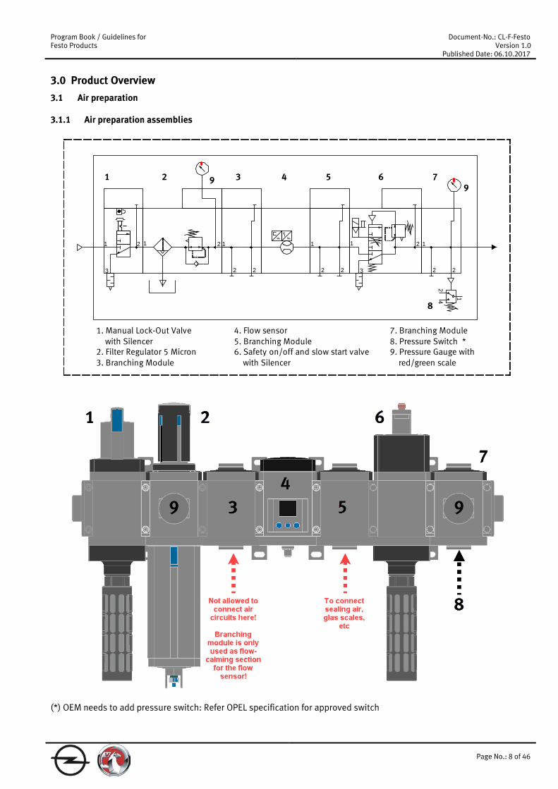
3.1.1 Air preparation assemblies
21
22
1
3
21
22
1
22
1
FF
42
1
2
3
1
1 2 3 4 5 6 7
8
99
1. Manual Lock-Out Valve with Silencer2. Filter Regulator 5 Micron3. Branching Module
7. Branching Module8. Pressure Switch *9. Pressure Gauge with red/green scale
4. Flow sensor5. Branching Module6. Safety on/off and slow start valve with Silencer
(*) OEM needs to add pressure switch: Refer OPEL specification for approved switch
Program Book / Guidelines for Festo Products
Document-No.: CL-F-Festo Version 1.0
Published Date: 06.10.2017
Page No.: 9 of 46
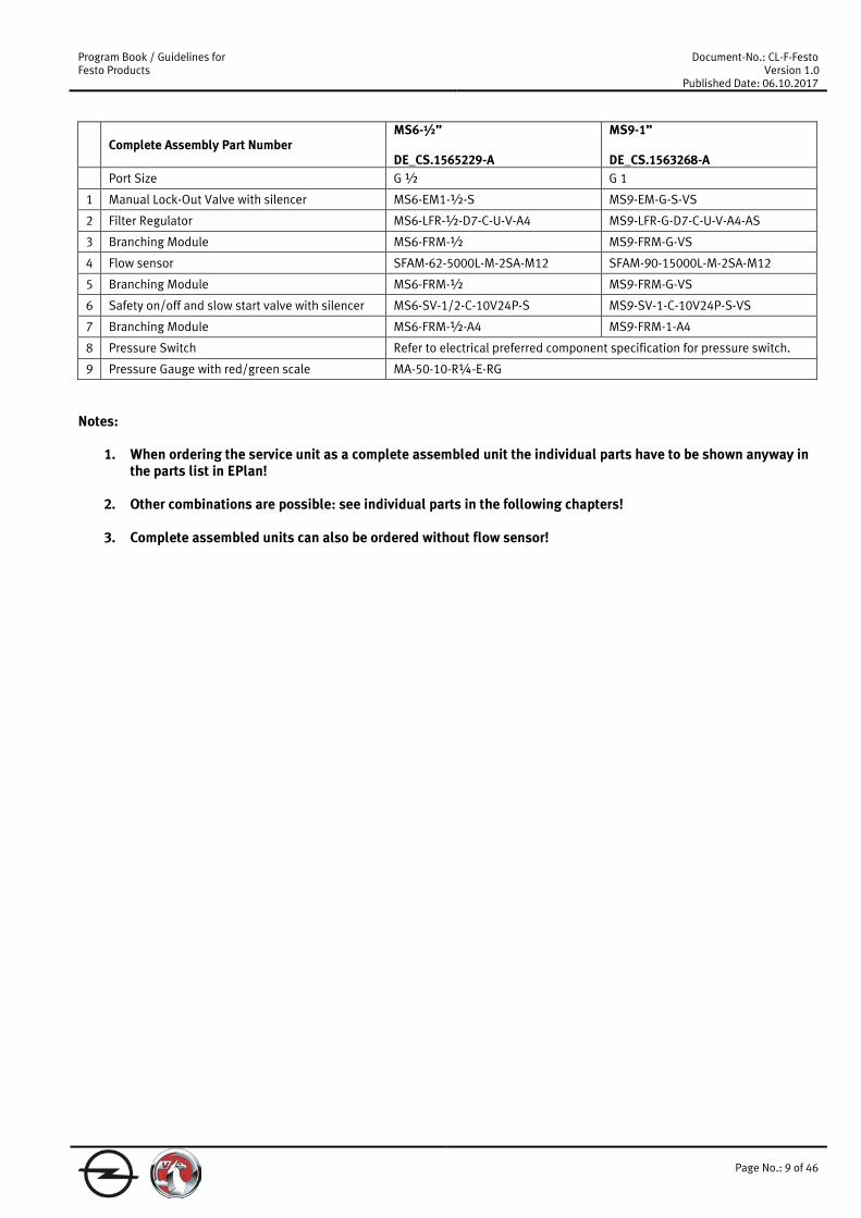
Complete Assembly Part Number MS6-½” DE_CS.1565229-A
MS9-1” DE_CS.1563268-A
Port Size G ½ G 1
1 Manual Lock-Out Valve with silencer MS6-EM1-½-S MS9-EM-G-S-VS
2 Filter Regulator MS6-LFR-½-D7-C-U-V-A4 MS9-LFR-G-D7-C-U-V-A4-AS
3 Branching Module MS6-FRM-½ MS9-FRM-G-VS
4 Flow sensor SFAM-62-5000L-M-2SA-M12 SFAM-90-15000L-M-2SA-M12
5 Branching Module MS6-FRM-½ MS9-FRM-G-VS
6 Safety on/off and slow start valve with silencer MS6-SV-1/2-C-10V24P-S MS9-SV-1-C-10V24P-S-VS
7 Branching Module MS6-FRM-½-A4 MS9-FRM-1-A4
8 Pressure Switch Refer to electrical preferred component specification for pressure switch.
9 Pressure Gauge with red/green scale MA-50-10-R¼-E-RG
Notes:
1. When ordering the service unit as a complete assembled unit the individual parts have to be shown anyway in the parts list in EPlan!
2. Other combinations are possible: see individual parts in the following chapters!
3. Complete assembled units can also be ordered without flow sensor!

Program Book / Guidelines for Festo Products
Document-No.: CL-F-Festo Version 1.0
Published Date: 06.10.2017
Page No.: 10 of 46
3.1.2 Pressure Lock-Out valve * Type Code Part number Ports Flow Description MS6-EM1-½ 541267 G ½ 8700 l/min On-Off Valve
MS9-EM-G-VS 562178 not threaded 18000 l/min On-Off Valve
MS12-EM-G 541495 not threaded 25000 l/min On-Off Valve * For single applications all Lock-out valves could be combined with each size of connecting/end plates.
3.1.3 5 Micron standard filters Filters with Metal Bowls and Auto Drains Type Code Part number Ports Flow Description MS4-LF-1/8-C-U-V 527695 * G 1/8 1000 l/min Filter
MS4-LF-¼-C-U-V 527695 * G ¼ 1300 l/min Filter
MS4-LF-AGC-CUV 527695 * G 3/8 1300 l/min Filter
MS6-LF-¼-C-U-V 527668 * G ¼ 2000 l/min Filter
MS6-LF-3/8-C-U-V 527668 * G 3/8 3000 l/min Filter
MS6-LF-½-CUV 529613 G ½ 3200 l/min Filter
MS6-LF-AGE-C-U-V 527668 * G ¾ 3200 l/min Filter
MS9-LF-AGD-C-U-V 562532 * G ½ 6000 l/min Filter
MS9-LF-AGE-C-U-V 562532 * G ¾ 8500 l/min Filter
MS9-LF-AGF-C-U-V 562532 * G 1 9500 l/min Filter
MS9-LF-AGG-C-U-V 562532 * G 1 ¼ 9500 l/min Filter
MS9-LF-AGH-C-U-V 562532 * G 1 ½ 9500 l/min Filter
MS12-LF-AGF-C-U-V 535023 * G 1 11500 l/min Filter
MS12-LF-AGG-C-U-V 535023 * G 1 ¼ 12500 l/min Filter
MS12-LF-AGH-C-U-V 535023 * G 1 ½ 13500 l/min Filter
MS12-LF-AGI-C-U-V 535023 * G 2 14000 l/min Filter * Configurable part, has to be specified in detail when ordering Replacement Filter Elements Type Code Part number Filtration Filter Description MS4-LFP-C 534501 5 Micron Fits All MS4 Filters Filter Cartridge
MS6-LFP-C 534499 5 Micron Fits All MS6 Filters Filter Cartridge
MS9-LFP-C 570309 5 Micron Fits All MS9 Filters Filter Cartridge
MS12-LFP-C 537143 5 Micron Fits All MS12 Filters Filter Cartridge
1 2
Program Book / Guidelines for Festo Products
Document-No.: CL-F-Festo Version 1.0
Published Date: 06.10.2017
Page No.: 11 of 46
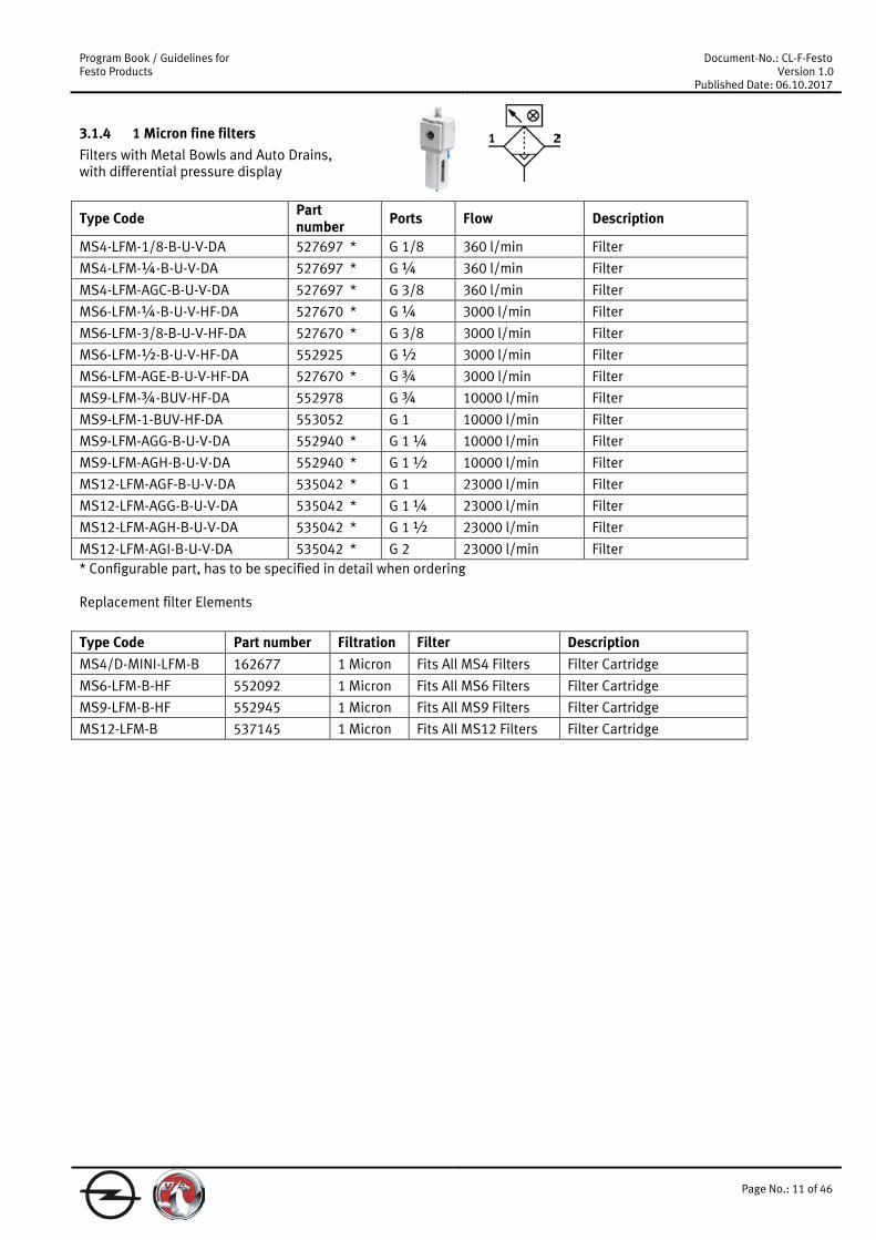
3.1.4 1 Micron fine filters Filters with Metal Bowls and Auto Drains, with differential pressure display
Type Code Part number Ports Flow Description
MS4-LFM-1/8-B-U-V-DA 527697 * G 1/8 360 l/min Filter
MS4-LFM-¼-B-U-V-DA 527697 * G ¼ 360 l/min Filter
MS4-LFM-AGC-B-U-V-DA 527697 * G 3/8 360 l/min Filter
MS6-LFM-¼-B-U-V-HF-DA 527670 * G ¼ 3000 l/min Filter
MS6-LFM-3/8-B-U-V-HF-DA 527670 * G 3/8 3000 l/min Filter
MS6-LFM-½-B-U-V-HF-DA 552925 G ½ 3000 l/min Filter
MS6-LFM-AGE-B-U-V-HF-DA 527670 * G ¾ 3000 l/min Filter
MS9-LFM-¾-BUV-HF-DA 552978 G ¾ 10000 l/min Filter
MS9-LFM-1-BUV-HF-DA 553052 G 1 10000 l/min Filter
MS9-LFM-AGG-B-U-V-DA 552940 * G 1 ¼ 10000 l/min Filter
MS9-LFM-AGH-B-U-V-DA 552940 * G 1 ½ 10000 l/min Filter
MS12-LFM-AGF-B-U-V-DA 535042 * G 1 23000 l/min Filter
MS12-LFM-AGG-B-U-V-DA 535042 * G 1 ¼ 23000 l/min Filter
MS12-LFM-AGH-B-U-V-DA 535042 * G 1 ½ 23000 l/min Filter
MS12-LFM-AGI-B-U-V-DA 535042 * G 2 23000 l/min Filter * Configurable part, has to be specified in detail when ordering Replacement filter Elements Type Code Part number Filtration Filter Description MS4/D-MINI-LFM-B 162677 1 Micron Fits All MS4 Filters Filter Cartridge
MS6-LFM-B-HF 552092 1 Micron Fits All MS6 Filters Filter Cartridge
MS9-LFM-B-HF 552945 1 Micron Fits All MS9 Filters Filter Cartridge
MS12-LFM-B 537145 1 Micron Fits All MS12 Filters Filter Cartridge

Program Book / Guidelines for Festo Products
Document-No.: CL-F-Festo Version 1.0
Published Date: 06.10.2017
Page No.: 12 of 46
3.1.5 0.01 Micron Micro filters Filters with Metal Bowls and Auto Drains, with differential pressure display Type Code Part number Ports Flow Description MS4-LFM-1/8-A-U-V-DA 527697 * G 1/8 360 l/min Filter
MS4-LFM-¼-AUV-DA 537214 * G ¼ 360 l/min Filter
MS4-LFM-AGC-A-U-V-DA 527697 * G 3/8 360 l/min Filter
MS6-LFM-¼-A-U-V-HF-DA 527670 * G ¼ 2500 l/min Filter
MS6-LFM-3/8-A-U-V-HF-DA 527670 * G 3/8 2500 l/min Filter
MS6-LFM-½-AUV-HF-DA 552926 G ½ 2500 l/min Filter
MS6-LFM-AGE-A-U-V-HF-DA 527670 * G ¾ 2500 l/min Filter
MS9-LFM-¾-AUV-HF-DA 552974 G ¾ 7800 l/min Filter
MS9-LFM-1-AUV-HF-DA 553048 G 1 7800 l/min Filter
MS9-LFM-AGG-A-U-V-DA 552940 * G 1 ¼ 7800 l/min Filter
MS9-LFM-AGH-A-U-V-DA 552940 * G 1 ½ 7800 l/min Filter
MS12-LFM-AGF-A-U-V-DA 535042 * G 1 23000 l/min Filter
MS12-LFM-AGG-A-U-V-DA 535042 * G 1 ¼ 23000 l/min Filter
MS12-LFM-AGH-A-U-V-DA 535042 * G 1 ½ 23000 l/min Filter
MS12-LFM-AGI-A-U-V-DA 535042 * G 2 23000 l/min Filter * Configurable part, has to be specified in detail when ordering Replacement filter Elements Type Code Part number Filtration Filter Description MS4/D-MINI-LFM-A 162674 0.01 Micron Fits All MS4 Filters Filter Cartridge
MS6-LFM-A-HF 552093 0.01 Micron Fits All MS6 Filters Filter Cartridge
MS9-LFM-A-HF 552944 0.01 Micron Fits All MS9 Filters Filter Cartridge
MS12-LFM-A 537146 0.01 Micron Fits All MS12 Filters Filter Cartridge
Program Book / Guidelines for Festo Products
Document-No.: CL-F-Festo Version 1.0
Published Date: 06.10.2017
Page No.: 13 of 46
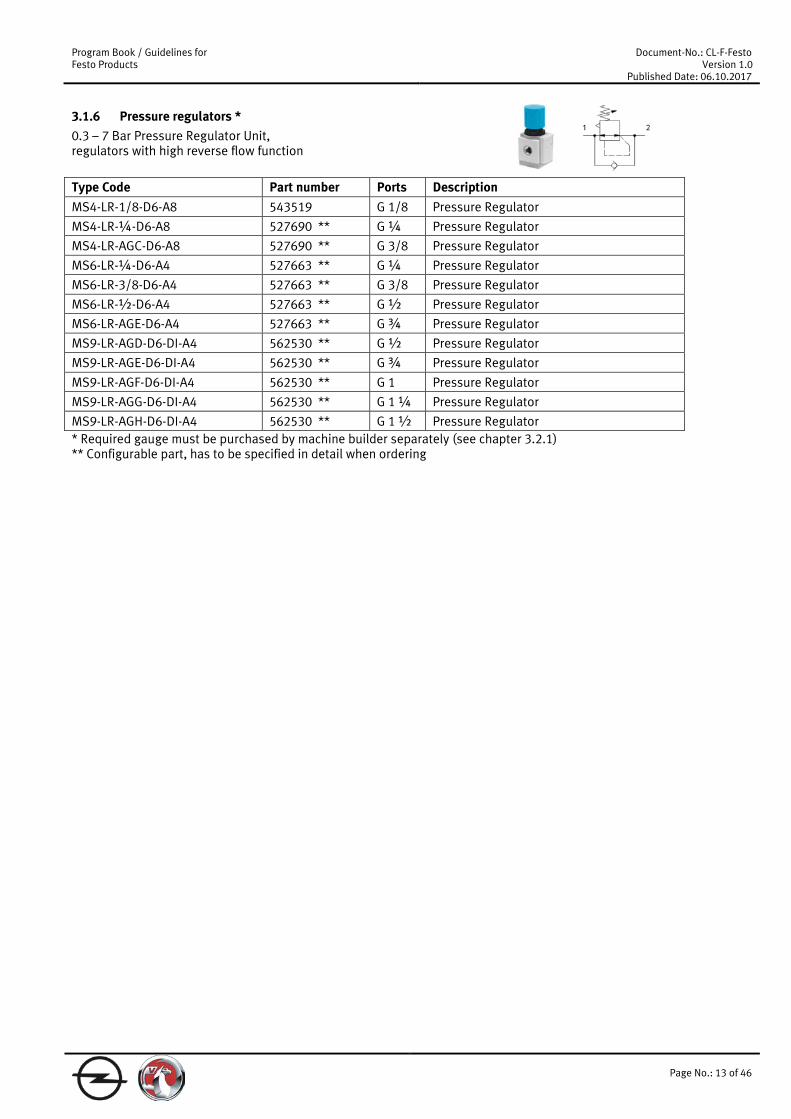
3.1.6 Pressure regulators * 0.3 – 7 Bar Pressure Regulator Unit, regulators with high reverse flow function Type Code Part number Ports Description MS4-LR-1/8-D6-A8 543519 G 1/8 Pressure Regulator
MS4-LR-¼-D6-A8 527690 ** G ¼ Pressure Regulator
MS4-LR-AGC-D6-A8 527690 ** G 3/8 Pressure Regulator
MS6-LR-¼-D6-A4 527663 ** G ¼ Pressure Regulator
MS6-LR-3/8-D6-A4 527663 ** G 3/8 Pressure Regulator
MS6-LR-½-D6-A4 527663 ** G ½ Pressure Regulator
MS6-LR-AGE-D6-A4 527663 ** G ¾ Pressure Regulator
MS9-LR-AGD-D6-DI-A4 562530 ** G ½ Pressure Regulator
MS9-LR-AGE-D6-DI-A4 562530 ** G ¾ Pressure Regulator
MS9-LR-AGF-D6-DI-A4 562530 ** G 1 Pressure Regulator
MS9-LR-AGG-D6-DI-A4 562530 ** G 1 ¼ Pressure Regulator
MS9-LR-AGH-D6-DI-A4 562530 ** G 1 ½ Pressure Regulator * Required gauge must be purchased by machine builder separately (see chapter 3.2.1) ** Configurable part, has to be specified in detail when ordering
Program Book / Guidelines for Festo Products
Document-No.: CL-F-Festo Version 1.0
Published Date: 06.10.2017
Page No.: 14 of 46
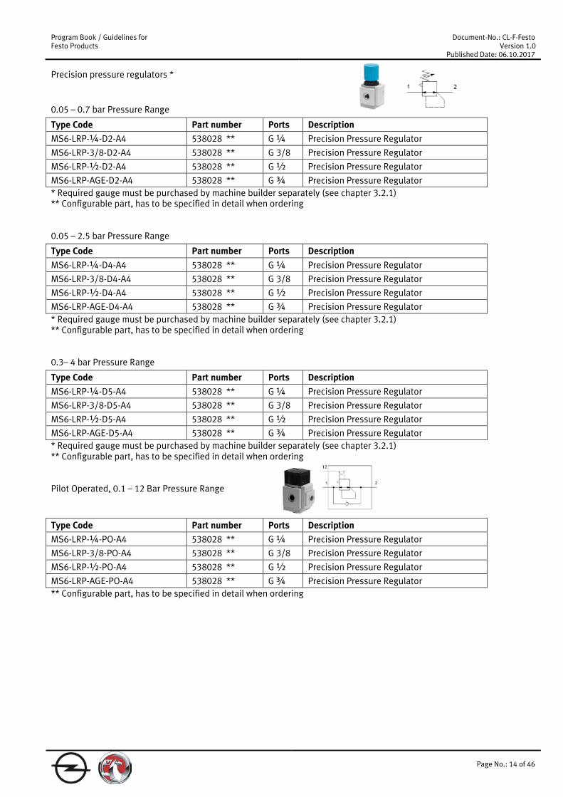
Precision pressure regulators * 0.05 – 0.7 bar Pressure Range
Type Code Part number Ports Description MS6-LRP-¼-D2-A4 538028 ** G ¼ Precision Pressure Regulator
MS6-LRP-3/8-D2-A4 538028 ** G 3/8 Precision Pressure Regulator
MS6-LRP-½-D2-A4 538028 ** G ½ Precision Pressure Regulator
MS6-LRP-AGE-D2-A4 538028 ** G ¾ Precision Pressure Regulator * Required gauge must be purchased by machine builder separately (see chapter 3.2.1) ** Configurable part, has to be specified in detail when ordering 0.05 – 2.5 bar Pressure Range
Type Code Part number Ports Description MS6-LRP-¼-D4-A4 538028 ** G ¼ Precision Pressure Regulator
MS6-LRP-3/8-D4-A4 538028 ** G 3/8 Precision Pressure Regulator
MS6-LRP-½-D4-A4 538028 ** G ½ Precision Pressure Regulator
MS6-LRP-AGE-D4-A4 538028 ** G ¾ Precision Pressure Regulator * Required gauge must be purchased by machine builder separately (see chapter 3.2.1) ** Configurable part, has to be specified in detail when ordering 0.3– 4 bar Pressure Range
Type Code Part number Ports Description MS6-LRP-¼-D5-A4 538028 ** G ¼ Precision Pressure Regulator
MS6-LRP-3/8-D5-A4 538028 ** G 3/8 Precision Pressure Regulator
MS6-LRP-½-D5-A4 538028 ** G ½ Precision Pressure Regulator
MS6-LRP-AGE-D5-A4 538028 ** G ¾ Precision Pressure Regulator * Required gauge must be purchased by machine builder separately (see chapter 3.2.1) ** Configurable part, has to be specified in detail when ordering Pilot Operated, 0.1 – 12 Bar Pressure Range Type Code Part number Ports Description MS6-LRP-¼-PO-A4 538028 ** G ¼ Precision Pressure Regulator
MS6-LRP-3/8-PO-A4 538028 ** G 3/8 Precision Pressure Regulator
MS6-LRP-½-PO-A4 538028 ** G ½ Precision Pressure Regulator
MS6-LRP-AGE-PO-A4 538028 ** G ¾ Precision Pressure Regulator ** Configurable part, has to be specified in detail when ordering

Program Book / Guidelines for Festo Products
Document-No.: CL-F-Festo Version 1.0
Published Date: 06.10.2017
Page No.: 15 of 46
3.1.7 5 Micron filter/regulators * 0.3 – 7 Bar Pressure Regulator Unit, Regulators with high reverse flow function, metal filter bowl and automatic drain Type Code Part number Ports Description MS4-LFR-1/8-D6-C-U-V-A8 526489 ** G 1/8 Filter Regulator
MS4-LFR-¼-D6-C-U-V-A8 526489 ** G ¼ Filter Regulator
MS4-LFR-AGC-D6-C-U-V-A8 526489 ** G 3/8 Filter Regulator
MS6-LFR-¼-D6-C-U-V-A4 526490 ** G ¼ Filter Regulator
MS6-LFR-3/8-D6-C-U-V-A4 526490 ** G 3/8 Filter Regulator
MS6-LFR-½-D6-C-U-V-A4 526490 ** G ½ Filter Regulator
MS6-LFR-AGE-D6-C-U-V-A4 526490 ** G ¾ Filter Regulator
MS9-LFR-AGD-D6-C-U-V-DI-A4 562531 ** G ½ Filter Regulator
MS9-LFR-AGE-D6-C-U-V-DI-A4 562531 ** G ¾ Filter Regulator
MS9-LFR-AGF-D6-C-U-V-DI-A4 562531 ** G 1 Filter Regulator
MS9-LFR-AGG-D6-C-U-V-DI-A4 562531 ** G 1 ¼ Filter Regulator
MS9-LFR-AGH-D6-C-U-V-DI-A4 562531 ** G 1 ½ Filter Regulator * Required gauge must be purchased by machine builder separately (see chapter 3.2.1) ** Configurable part, has to be specified in detail when ordering
1 2

Program Book / Guidelines for Festo Products
Document-No.: CL-F-Festo Version 1.0
Published Date: 06.10.2017
Page No.: 16 of 46
0.3 – 7 Bar Pressure Regulator Unit, Regulators without high reverse flow function, metal filter bowl and automatic drain Type Code Part number Ports Description MS4-LFR-1/8-D6-C-U-V-A8-OS 526489 ** G 1/8 Filter Regulator
MS4-LFR-¼-D6-C-U-V-A8-OS 526489 ** G ¼ Filter Regulator
MS4-LFR-AGC-D6-C-U-V-A8-OS 526489 ** G 3/8 Filter Regulator
MS6-LFR-¼-D6-C-U-V-A4-OS 526490 ** G ¼ Filter Regulator
MS6-LFR-3/8-D6-C-U-V-A4-OS 526490 ** G 3/8 Filter Regulator
MS6-LFR-½-D6-C-U-V-A4-OS 526490 ** G ½ Filter Regulator
MS6-LFR-AGE-D6-C-U-V-A4-OS 526490 ** G ¾ Filter Regulator
MS9-LFR-AGD-D6-C-U-V-DI-A4-OS 562531 ** G ½ Filter Regulator
MS9-LFR-AGE-D6-C-U-V-DI-A4-OS 562531 ** G ¾ Filter Regulator
MS9-LFR-AGF-D6-C-U-V-DI-A4-OS 562531 ** G 1 Filter Regulator
MS9-LFR-AGG-D6-C-U-V-DI-A4-OS 562531 ** G 1 ¼ Filter Regulator
MS9-LFR-AGH-D6-C-U-V-DI-A4-OS 562531 ** G 1 ½ Filter Regulator
MS12-LFR-AGF-D6-C-U-V-A4-LD 535022 ** G 1 Filter Regulator
MS12-LFR-AGG-D6-C-U-V-A4-LD 535022 ** G 1 ¼ Filter Regulator
MS12-LFR-AGH-D6-C-U-V-A4-LD 535022 ** G 1 ½ Filter Regulator
MS12-LFR-AGI-D6-C-U-V-A4-LD 535022 ** G 2 Filter Regulator * Required gauge must be purchased by machine builder separately (see chapter 3.2.1) ** Configurable part, has to be specified in detail when ordering Replacement filter Elements Type Code Part number Filtration Filter Description MS4-LFP-C 534501 5 Micron Fits All MS4 Filters Filter Cartridge
MS6-LFP-C 534499 5 Micron Fits All MS6 Filters Filter Cartridge
MS9-LFP-C 570309 5 Micron Fits All MS9 Filters Filter Cartridge
MS12-LFP-C 537143 5 Micron Fits All MS12 Filters Filter Cartridge

Program Book / Guidelines for Festo Products
Document-No.: CL-F-Festo Version 1.0
Published Date: 06.10.2017
Page No.: 17 of 46
3.1.8 On/off valve and slow start valves 24VDC Solenoid On/Off Valve with Manual over Ride Type Code Part number Ports Description MS4-EE-1/8-10V24 ** 542580 G 1/8 On-Off Valve MS4-EE-¼-10V24 ** 542578 G ¼ On-Off Valve MS4-EE-AGC-10V24 ** 527709 * G 3/8 On-Off Valve MS6-EE-¼-10V24 ** 542584 G ¼ On-Off Valve MS6-EE-3/8-10V24 ** 542586 G 3/8 On-Off Valve
MS6-EE-½-10V24 ** 542582 G ½ On-Off Valve
MS6-EE-AGE-10V24 ** 527682 * G ¾ On-Off Valve
MS9-EE-AGD-V24-VS ** 562177 * G ½ On-Off Valve
MS9-EE-AGE-V24-VS ** 562177 * G ¾ On-Off Valve
MS9-EE-AGF-V24-VS ** 562177 * G 1 On-Off Valve MS9-EE-AGG-V24-VS ** 562177 * G 1 ¼ On-Off Valve MS9-EE-AGH-V24-VS ** 562177 * G 1 ½ On-Off Valve MS12-EE-AGF-V24 ** 535032 * G 1 On-Off Valve MS12-EE-AGG-V24 ** 535032 * G 1 ¼ On-Off Valve MS12-EE-AGH-V24 ** 535032 * G 1 ½ On-Off Valve MS12-EE-AGI-V24 ** 535032 * G 2 On-Off Valve
MSSD-EB-M12-MONO 188024 -- Socket for On-Off-valves, M12x1, for size MS4 and MS6
MSSD-C-24-LED-M12-SA-27400 188513 -- Socket for On-Off-valves, M12x1, for size MS9 and MS12
* Configurable part, has to be specified in detail when ordering ** Mandatory to use socket with electrical On/Off valve! Slow start valves Type Code Part number Ports Description MS4-DL-1/8 529533 G 1/8 Soft-Start Valve
MS4-DL-¼ 529531 G ¼ Soft-Start Valve
MS4-DL-AGC 527711 * G 3/8 Soft-Start Valve
MS6-DL-¼ 529819 G ¼ Soft-Start Valve
MS6-DL-3/8 529821 G 3/8 Soft-Start Valve
MS6-DL-½ 529817 G ½ Soft-Start Valve
MS6-DL-AGE 527684 * G ¾ Soft-Start Valve
MS12-DL-AGF 535033 * G 1 Soft-Start Valve
MS12-DL-AGG 535033 * G 1 ¼ Soft-Start Valve
MS12-DL-AGH 535033 * G 1 ½ Soft-Start Valve
MS12-DL-AGI 535033 * G 2 Soft-Start Valve * Configurable part, has to be specified in detail when ordering

Program Book / Guidelines for Festo Products
Document-No.: CL-F-Festo Version 1.0
Published Date: 06.10.2017
Page No.: 18 of 46
3.1.9 Safety On/off valve and slow start valves to EN ISO 13849-1 Type Code Part number Ports Description Performance level C, Kat. 1
MS6-SV-1/2-C-10V24P-S 548713 * G ½ Safety valve, flow 5700 l/min, 24VDC, with silencer
MS9-SV-1-C-10V24P-S-VS 562176 * G 1 Safety valve, flow 16460 l/min, 24VDC, with silencer
Performance level D, Kat. 3
MS6-SV-1/2-D-10V24P-2M12-SO 548713 * G ½ Safety valve, flow 4300 l/min, 24VDC, with silencer
Performance level E, Kat. 4
MS6-SV-1/2-E-10V24-SO 548713 * G ½ Safety valve, flow 4300 l/min, 24VDC, with silencer
Electrical adapter
NECA-S1G9-P9-MP5 573695 Multi-pin plug socket, Operating voltage range DC 21,6 … 26,4 V, protection class IP65, for MS6-SV-E
* Configurable part, has to be specified in detail when ordering
3.1.10 Flow Sensor
Type Code Part number Size Flow measurement range Description
SFAM-62-1000L-M-2SA-M12 564930 MS6 max. 1000 l/min 2x PNP or NPN, 1 analogue output 4 … 20 mA, straight plug, M12x1, 5-pin
SFAM-62-5000L-M-2SA-M12 564938 MS6 max. 5000 l/min flow measurement range, 2x PNP or NPN, 1 analogue output 4 … 20 mA, straight plug, M12x1, 5-pin
SFAM-90-15000L-M-2SA-M12 573350 MS9 max. 15000 l/min flow measurement range, 2x PNP or NPN, 1 analogue output 4 … 20 mA, straight plug, M12x1, 5-pin
FF
Program Book / Guidelines for Festo Products
Document-No.: CL-F-Festo Version 1.0
Published Date: 06.10.2017
Page No.: 19 of 46
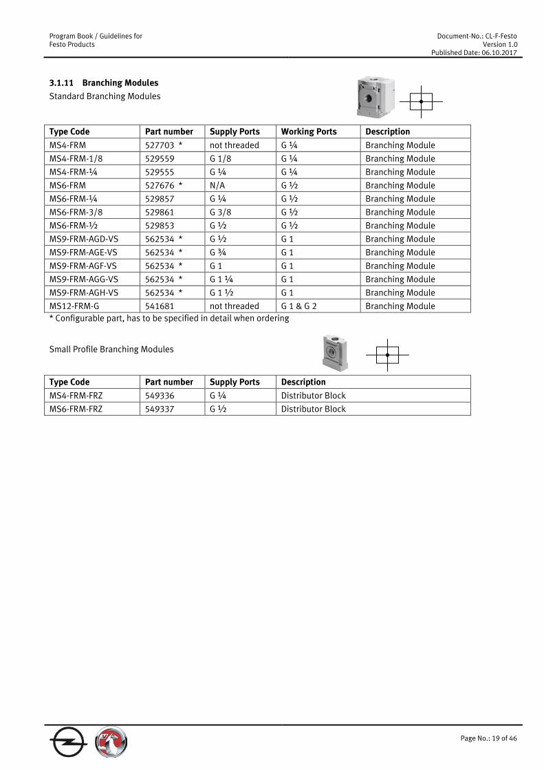
3.1.11 Branching Modules Standard Branching Modules Type Code Part number Supply Ports Working Ports Description MS4-FRM 527703 * not threaded G ¼ Branching Module
MS4-FRM-1/8 529559 G 1/8 G ¼ Branching Module
MS4-FRM-¼ 529555 G ¼ G ¼ Branching Module
MS6-FRM 527676 * N/A G ½ Branching Module
MS6-FRM-¼ 529857 G ¼ G ½ Branching Module
MS6-FRM-3/8 529861 G 3/8 G ½ Branching Module
MS6-FRM-½ 529853 G ½ G ½ Branching Module
MS9-FRM-AGD-VS 562534 * G ½ G 1 Branching Module
MS9-FRM-AGE-VS 562534 * G ¾ G 1 Branching Module
MS9-FRM-AGF-VS 562534 * G 1 G 1 Branching Module
MS9-FRM-AGG-VS 562534 * G 1 ¼ G 1 Branching Module
MS9-FRM-AGH-VS 562534 * G 1 ½ G 1 Branching Module
MS12-FRM-G 541681 not threaded G 1 & G 2 Branching Module * Configurable part, has to be specified in detail when ordering Small Profile Branching Modules Type Code Part number Supply Ports Description MS4-FRM-FRZ 549336 G ¼ Distributor Block
MS6-FRM-FRZ 549337 G ½ Distributor Block
Program Book / Guidelines for Festo Products
Document-No.: CL-F-Festo Version 1.0
Published Date: 06.10.2017
Page No.: 20 of 46
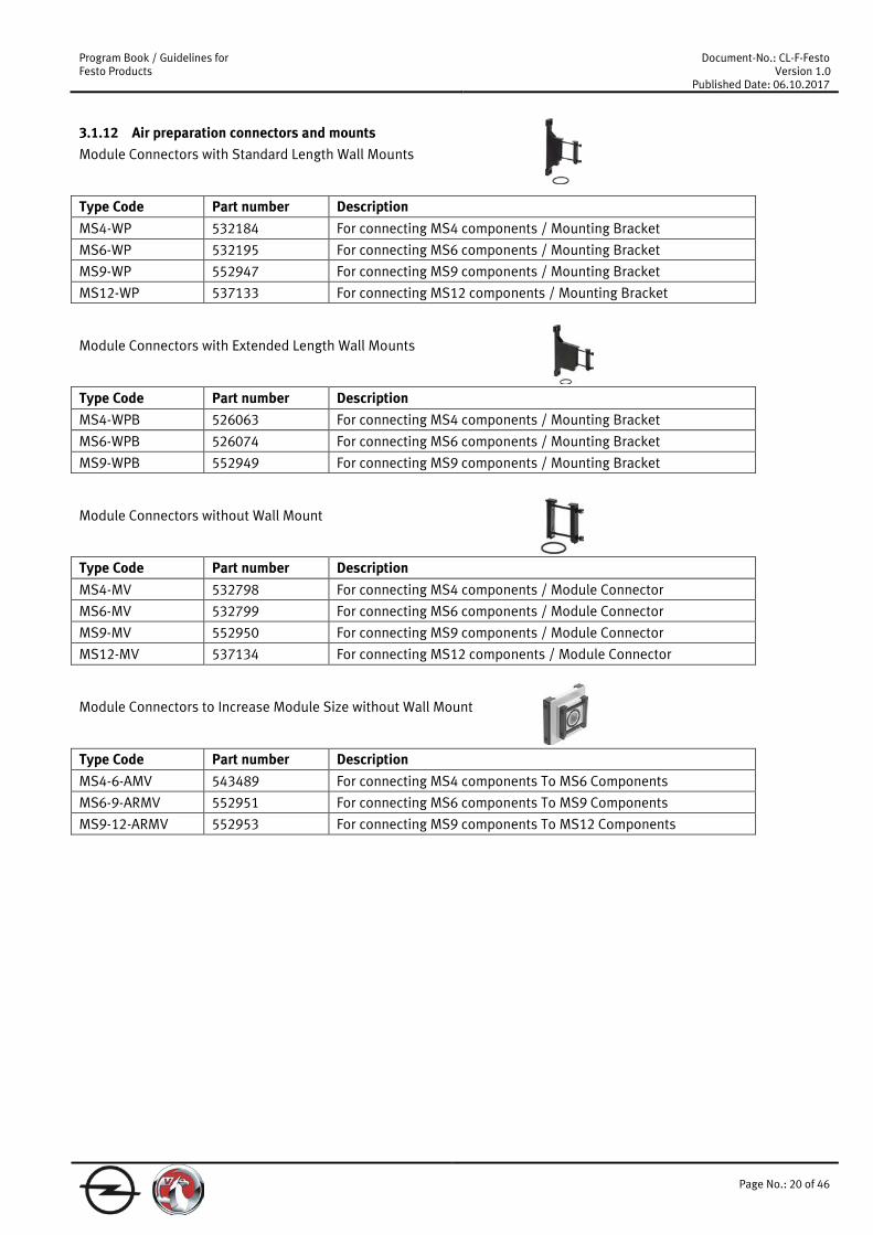
3.1.12 Air preparation connectors and mounts Module Connectors with Standard Length Wall Mounts Type Code Part number Description MS4-WP 532184 For connecting MS4 components / Mounting Bracket
MS6-WP 532195 For connecting MS6 components / Mounting Bracket
MS9-WP 552947 For connecting MS9 components / Mounting Bracket
MS12-WP 537133 For connecting MS12 components / Mounting Bracket Module Connectors with Extended Length Wall Mounts Type Code Part number Description MS4-WPB 526063 For connecting MS4 components / Mounting Bracket
MS6-WPB 526074 For connecting MS6 components / Mounting Bracket
MS9-WPB 552949 For connecting MS9 components / Mounting Bracket Module Connectors without Wall Mount Type Code Part number Description MS4-MV 532798 For connecting MS4 components / Module Connector
MS6-MV 532799 For connecting MS6 components / Module Connector
MS9-MV 552950 For connecting MS9 components / Module Connector
MS12-MV 537134 For connecting MS12 components / Module Connector Module Connectors to Increase Module Size without Wall Mount Type Code Part number Description MS4-6-AMV 543489 For connecting MS4 components To MS6 Components
MS6-9-ARMV 552951 For connecting MS6 components To MS9 Components
MS9-12-ARMV 552953 For connecting MS9 components To MS12 Components

Program Book / Guidelines for Festo Products
Document-No.: CL-F-Festo Version 1.0
Published Date: 06.10.2017
Page No.: 21 of 46
3.1.13 Timer modules Part number Type Code Description
Valve with electrical timer function VSVA-B-TR1-B52-ZD-D1-1R5L-CS-1464353-A
Size ISO1, bistable 5/2 valve, with integrated condensator which allows to switch the valve back after a defined time, with mounted manual override caps (541011 VAMC-S6-CS) for function “locked”
9484 NAS-1/4-1A-ISO Individual Sub Base, 42 mm width, only to use with timer valve
Attention: Valve needs external pilot air via the sub base!
Note: This valve has to be used for no automatic pressure release applications, e.g.
- glass scales - sealing air - afterblow functions
Program Book / Guidelines for Festo Products
Document-No.: CL-F-Festo Version 1.0
Published Date: 06.10.2017
Page No.: 22 of 46
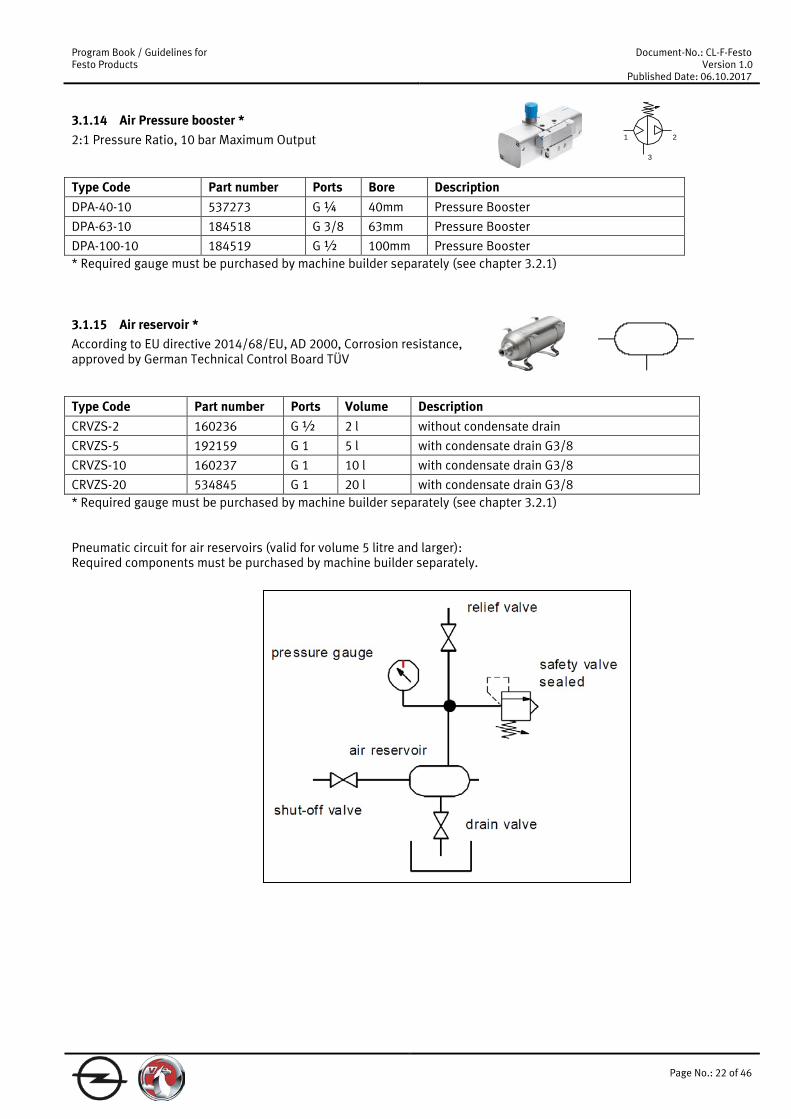
3.1.14 Air Pressure booster * 2:1 Pressure Ratio, 10 bar Maximum Output Type Code Part number Ports Bore Description DPA-40-10 537273 G ¼ 40mm Pressure Booster
DPA-63-10 184518 G 3/8 63mm Pressure Booster
DPA-100-10 184519 G ½ 100mm Pressure Booster * Required gauge must be purchased by machine builder separately (see chapter 3.2.1)
3.1.15 Air reservoir * According to EU directive 2014/68/EU, AD 2000, Corrosion resistance, approved by German Technical Control Board TÜV Type Code Part number Ports Volume Description CRVZS-2 160236 G ½ 2 l without condensate drain
CRVZS-5 192159 G 1 5 l with condensate drain G3/8
CRVZS-10 160237 G 1 10 l with condensate drain G3/8
CRVZS-20 534845 G 1 20 l with condensate drain G3/8 * Required gauge must be purchased by machine builder separately (see chapter 3.2.1) Pneumatic circuit for air reservoirs (valid for volume 5 litre and larger): Required components must be purchased by machine builder separately.
1
3
2
Program Book / Guidelines for Festo Products
Document-No.: CL-F-Festo Version 1.0
Published Date: 06.10.2017
Page No.: 23 of 46
3.2 Accessories
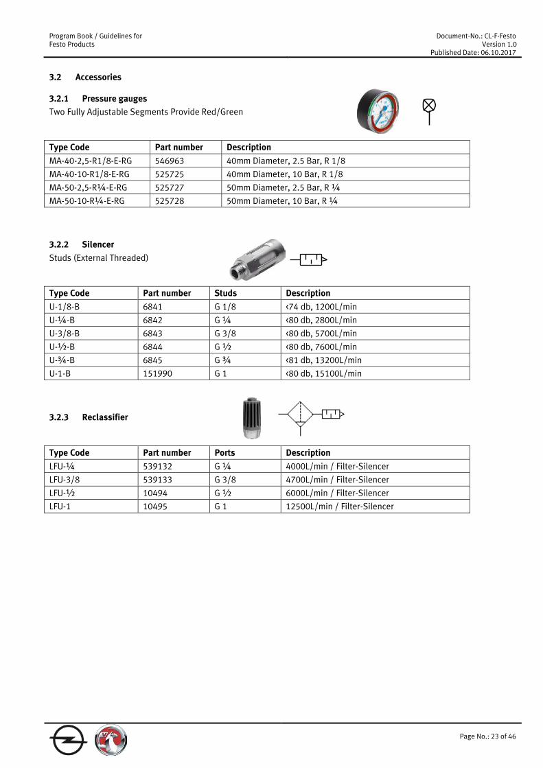
3.2.1 Pressure gauges Two Fully Adjustable Segments Provide Red/Green Type Code Part number Description MA-40-2,5-R1/8-E-RG 546963 40mm Diameter, 2.5 Bar, R 1/8
MA-40-10-R1/8-E-RG 525725 40mm Diameter, 10 Bar, R 1/8
MA-50-2,5-R¼-E-RG 525727 50mm Diameter, 2.5 Bar, R ¼
MA-50-10-R¼-E-RG 525728 50mm Diameter, 10 Bar, R ¼
3.2.2 Silencer Studs (External Threaded) Type Code Part number Studs Description U-1/8-B 6841 G 1/8 <74 db, 1200L/min
U-¼-B 6842 G ¼ <80 db, 2800L/min
U-3/8-B 6843 G 3/8 <80 db, 5700L/min
U-½-B 6844 G ½ <80 db, 7600L/min
U-¾-B 6845 G ¾ <81 db, 13200L/min
U-1-B 151990 G 1 <80 db, 15100L/min
3.2.3 Reclassifier Type Code Part number Ports Description LFU-¼ 539132 G ¼ 4000L/min / Filter-Silencer
LFU-3/8 539133 G 3/8 4700L/min / Filter-Silencer
LFU-½ 10494 G ½ 6000L/min / Filter-Silencer
LFU-1 10495 G 1 12500L/min / Filter-Silencer
Program Book / Guidelines for Festo Products
Document-No.: CL-F-Festo Version 1.0
Published Date: 06.10.2017
Page No.: 24 of 46
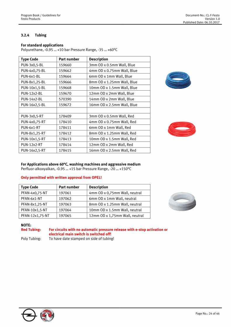
3.2.4 Tubing For standard applications Polyurethane, -0.95 … +10 bar Pressure Range, -35 … +60°C Type Code Part number Description PUN-3x0,5-BL 159660 3mm OD x 0.5mm Wall, Blue
PUN-4x0,75-BL 159662 4mm OD x 0.75mm Wall, Blue
PUN-6x1-BL 159664 6mm OD x 1mm Wall, Blue
PUN-8x1,25-BL 159666 8mm OD x 1.25mm Wall, Blue
PUN-10x1,5-BL 159668 10mm OD x 1.5mm Wall, Blue
PUN-12x2-BL 159670 12mm OD x 2mm Wall, Blue
PUN-14x2-BL 570390 14mm OD x 2mm Wall, Blue
PUN-16x2,5-BL 159672 16mm OD x 2.5mm Wall, Blue
PUN-3x0,5-RT 178409 3mm OD x 0.5mm Wall, Red
PUN-4x0,75-RT 178410 4mm OD x 0.75mm Wall, Red
PUN-6x1-RT 178411 6mm OD x 1mm Wall, Red
PUN-8x1,25-RT 178412 8mm OD x 1.25mm Wall, Red
PUN-10x1,5-RT 178413 10mm OD x 1.5mm Wall, Red
PUN-12x2-RT 178414 12mm OD x 2mm Wall, Red
PUN-16x2,5-RT 178415 16mm OD x 2.5mm Wall, Red For Applications above 60°C, washing machines and aggressive medium Perfluor-alkoxyalkan, -0.95 … +15 bar Pressure Range, -20 … +150°C Only permitted with written approval from OPEL! Type Code Part number Description PFAN-4x0,75-NT 197061 4mm OD x 0,75mm Wall, neutral
PFAN-6x1-NT 197062 6mm OD x 1mm Wall, neutral
PFAN-8x1,25-NT 197063 8mm OD x 1.25mm Wall, neutral
PFAN-10x1,5-NT 197064 10mm OD x 1.5mm Wall, neutral
PFAN-12x1,75-NT 197065 12mm OD x 1,75mm Wall, neutral NOTE: Red Tubing: For circuits with no automatic pressure release with e-stop activation or
electrical main switch is switched off! Poly Tubing: To have date stamped on side of tubing!

Program Book / Guidelines for Festo Products
Document-No.: CL-F-Festo Version 1.0
Published Date: 06.10.2017
Page No.: 25 of 46
3.2.5 Degree Flow Controls Meter out Flow Controls Studs (External Threaded) Type Code Part number Ports/Studs Description GRLA-M5-B 151160 M5 One-Way Flow Control Valve
GRLA-1/8-B 151165 G 1/8 One-Way Flow Control Valve
GRLA-¼-B 151172 G ¼ One-Way Flow Control Valve
GRLA-3/8-B 151178 G 3/8 One-Way Flow Control Valve
GRLA-½-B 151179 G ½ One-Way Flow Control Valve
GRLA-¾-B 151180 G ¾ One-Way Flow Control Valve Meter out Flow Controls, tamper-proof with spring pin Studs (External Threaded) Type Code Part number Ports/Studs Description GRLA-M5-B-SA-218543 539717 M5 tamper-proof with spring pin
GRLA-1/8-B-SA-218537 539661 G 1/8 tamper-proof with spring pin
GRLA-¼-B-SA-218536 539662 G ¼ tamper-proof with spring pin
GRLA-3/8-B-SA-218541 539715 G 3/8 tamper-proof with spring pin
GRLA-½-B-SA-218540 539716 G ½ tamper-proof with spring pin
GRLA-¾-B-SA-218542 539714 G ¾ tamper-proof with spring pin After adjusting the spring pin has to be pressed in to be tamper-proof! Meter out Flow Controls with Push Pull Fitting Type Code Part number Ports/Studs Description VFOH-LE-A-G18-Q4 578797 G 1/8 & 4mm OD Tube Fitting One-Way Flow Control Valve
VFOH-LE-A-G18-Q6 578798 G 1/8 & 6mm OD Tube Fitting One-Way Flow Control Valve
VFOH-LE-A-G18-Q8 578799 G 1/8 & 8mm OD Tube Fitting One-Way Flow Control Valve
VFOH-LE-A-G14-Q8 578800 G ¼ & 8mm OD Tube Fitting One-Way Flow Control Valve
VFOH-LE-A-G14-Q10 578801 G ¼ & 10mm OD Tube Fitting One-Way Flow Control Valve Meter in Flow Controls Type Code Part number Ports/Studs Description GRLZ-M5-B 151183 M5 One-Way Flow Control Valve
GRLZ-1/8-B 151188 G 1/8 One-Way Flow Control Valve
GRLZ-¼-B 151195 G ¼ One-Way Flow Control Valve
2
1
1
2
2
1

Program Book / Guidelines for Festo Products
Document-No.: CL-F-Festo Version 1.0
Published Date: 06.10.2017
Page No.: 26 of 46
3.2.6 Inline Flow Controls Type Code Part number Ports Description GR-M5-B 151213 M5 One-Way Flow Control Valve
GR-1/8-B 151215 G 1/8 One-Way Flow Control Valve
GRA-¼-B 6509 G ¼ One-Way Flow Control Valve
GR-3/8-B 6308 G 3/8 One-Way Flow Control Valve
GR-½ 3720 G ½ One-Way Flow Control Valve
GR-¾ 2103 G ¾ One-Way Flow Control Valve
3.2.7 Pilot operated check valves Manual relief valve required Studs (External Threaded) 90 Degree Type Code Part number Working Port/Stud Pilot Port Description HGL-M5-B 530029 M5 M5 Non-Return Valve
HGL-1/8-B 530030 G 1/8 G 1/8 Non-Return Valve
HGL-¼-B 530031 G ¼ G ¼ Non-Return Valve
HGL-3/8-B 530032 G 3/8 G 3/8 Non-Return Valve
HGL-½-B 530033 G ½ G ½ Non-Return Valve Meter out Flow Controls with Push Pull Fitting With stopper function, manual exhaust function and QS push-in connector Type Code Part number Ports/Studs Description
VFOF-LE-BAH-G18-Q6 8001459 G 1/8 & 6mm OD Tube Fitting
One-way flow control valve, piloted non-return function, manual exhaust function
VFOF-LE-BAH-G14-Q8 1927030 G 1/4 & 8mm OD Tube Fitting
One-way flow control valve, piloted non-return function, manual exhaust function
Use plug 8030314 NPFC-R-G18-M5-FM to have M5 thread or other reducing nipples NPFC-R-…!
2
1
21
2
1

Program Book / Guidelines for Festo Products
Document-No.: CL-F-Festo Version 1.0
Published Date: 06.10.2017
Page No.: 27 of 46
3.2.8 Manual pressure release valve for use with pilot operated check valves 90 Degree Flow Control with integrated pilot operated check calve Studs (External Threaded) Type Code Part number Port/Stud Description HAB-1/8 184585 G 1/8 Male / Female Thread Manual Override
HAB-¼ 184586 G ¼ Male / Female Thread Manual Override
HAB-3/8 184587 G 3/8 Male / Female Thread Manual Override
HAB-½ 184588 G ½ Male / Female Thread Manual Override
3.2.9 Quick exhaust valves With ISO 228-1 threads with silencer Type Code Part number Ports Description SEU-1/8 4616 G 1/8 Quick Exhaust Valve
SEU-¼ 6753 G ¼ Quick Exhaust Valve
SEU-3/8 6755 G 3/8 Quick Exhaust Valve
SEU-½ 6822 G ½ Quick Exhaust Valve Without Silencer, Studs (External Threaded) Type Code Part number Port/Stud Description SE-1/8-B 9685 G 1/8 Quick Exhaust Valve
SE-¼-B 9686 G ¼ Quick Exhaust Valve
SE-3/8-B 9687 G 3/8 Quick Exhaust Valve
SE-½-B 9688 G ½ Quick Exhaust Valve
SE-¾ 2280 G ¾ Quick Exhaust Valve
1 2
31
2
1 3
2

Program Book / Guidelines for Festo Products
Document-No.: CL-F-Festo Version 1.0
Published Date: 06.10.2017
Page No.: 28 of 46
3.2.10 Fittings Stud ends comply with the ISO 228-1 standard Male Straight, Elbow & Tee Fittings, External Hex, Nickel Plated Brass, With O-ring Seal Type Code Description NPQH-D-... * Push-In Fitting, Push-In Connector, Push-In Sleeve
NPQH-DK-... * Push-In Fitting
NPQH-H-... * Push-In Bulkhead Fitting, Push-In Bulkhead Connector
NPQH-P-... * Blanking Plug
NPQH-BK-... * Plug Screw
NPQH-L-... * Push-In L-Fitting, Push-In L-Connector
NPQH-LL-... * Push-In L-Fitting Long
NPQH-T-... * Push-In T-Fitting, Push-In T-Connector
NPQH-Y-... * Push-In Y-Connector * Configurable part, has to be specified in detail when ordering
3.2.11 Air Gap Sensors 20 – 200μm Air Gap Sensor, 2 PNP Switch Outputs, 2 Colour LED Display, M12 Connection, 6mm Push-In Fittings 2.5 - 5μm Repetition accuracy Type Code Part number Description SOPA-CM1H-R1-WQ6-2P-M12 552138 Control Module And 1 Sensor Module
SOPA-CM2H-R1-WQ6-2P-M12 552139 Control Module And 2 Sensor Modules
SOPA-CM3H-R1-WQ6-2P-M12 552140 Control Module And 3 Sensor Modules
SOPA-CM4H-R1-WQ6-2P-M12 552141 Control Module And 4 Sensor Modules
SOPA-M1-R1-WQ6-2P-M12 549902 * Stand Alone Sensor Module * Configurable part, has to be specified in detail when ordering
3.2.12 Quick Coupling Socket and Plug Self-closing, for safety coupling per ISO 4414 Type Code Part number Description NPHS-D6-M-G14 8059275 Socket, male thread G ¼
NPHS-D6-M-G38 8059276 Socket, male thread G 3/8
NPHS-D6-M-G12 8059277 Socket, male thread G ½
NPHS-S6-M-G14 8059258 Plug, male thread G ¼
NPHS-S6-M-G38 8059259 Plug, male thread G 3/8
NPHS-S6-M-G12 8059260 Plug, male thread G ½
Program Book / Guidelines for Festo Products
Document-No.: CL-F-Festo Version 1.0
Published Date: 06.10.2017
Page No.: 29 of 46
3.3 ACTUATORS
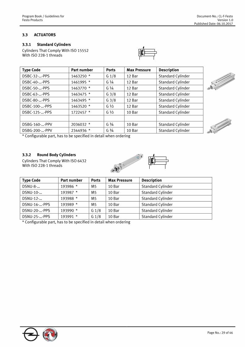
3.3.1 Standard Cylinders Cylinders That Comply With ISO 15552 With ISO 228-1 threads Type Code Part number Ports Max Pressure Description DSBC-32-…-PPS 1463250 * G 1/8 12 Bar Standard Cylinder
DSBC-40-…-PPS 1461995 * G ¼ 12 Bar Standard Cylinder
DSBC-50-…-PPS 1463770 * G ¼ 12 Bar Standard Cylinder
DSBC-63-…-PPS 1463475 * G 3/8 12 Bar Standard Cylinder
DSBC-80-…-PPS 1463495 * G 3/8 12 Bar Standard Cylinder
DSBC-100-…-PPS 1463520 * G ½ 12 Bar Standard Cylinder
DSBC-125-…-PPS 1722457 * G ½ 10 Bar Standard Cylinder
DSBG-160-…-PPV 2036032 * G ¾ 10 Bar Standard Cylinder
DSBG-200-…-PPV 2344936 * G ¾ 10 Bar Standard Cylinder * Configurable part, has to be specified in detail when ordering
3.3.2 Round Body Cylinders Cylinders That Comply With ISO 6432 With ISO 228-1 threads Type Code Part number Ports Max Pressure Description DSNU-8-… 193986 * M5 10 Bar Standard Cylinder
DSNU-10-… 193987 * M5 10 Bar Standard Cylinder
DSNU-12-… 193988 * M5 10 Bar Standard Cylinder
DSNU-16-…-PPS 193989 * M5 10 Bar Standard Cylinder
DSNU-20-…-PPS 193990 * G 1/8 10 Bar Standard Cylinder
DSNU-25-…-PPS 193991 * G 1/8 10 Bar Standard Cylinder * Configurable part, has to be specified in detail when ordering
Program Book / Guidelines for Festo Products
Document-No.: CL-F-Festo Version 1.0
Published Date: 06.10.2017
Page No.: 30 of 46
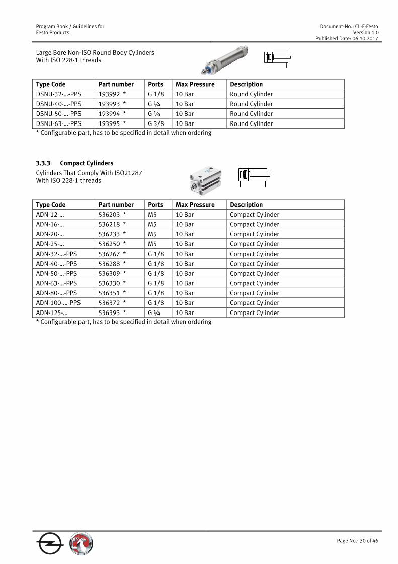
Large Bore Non-ISO Round Body Cylinders With ISO 228-1 threads Type Code Part number Ports Max Pressure Description DSNU-32-…-PPS 193992 * G 1/8 10 Bar Round Cylinder
DSNU-40-…-PPS 193993 * G ¼ 10 Bar Round Cylinder
DSNU-50-…-PPS 193994 * G ¼ 10 Bar Round Cylinder
DSNU-63-…-PPS 193995 * G 3/8 10 Bar Round Cylinder * Configurable part, has to be specified in detail when ordering
3.3.3 Compact Cylinders Cylinders That Comply With ISO21287 With ISO 228-1 threads Type Code Part number Ports Max Pressure Description ADN-12-… 536203 * M5 10 Bar Compact Cylinder
ADN-16-… 536218 * M5 10 Bar Compact Cylinder
ADN-20-… 536233 * M5 10 Bar Compact Cylinder
ADN-25-… 536250 * M5 10 Bar Compact Cylinder
ADN-32-…-PPS 536267 * G 1/8 10 Bar Compact Cylinder
ADN-40-…-PPS 536288 * G 1/8 10 Bar Compact Cylinder
ADN-50-…-PPS 536309 * G 1/8 10 Bar Compact Cylinder
ADN-63-…-PPS 536330 * G 1/8 10 Bar Compact Cylinder
ADN-80-…-PPS 536351 * G 1/8 10 Bar Compact Cylinder
ADN-100-…-PPS 536372 * G 1/8 10 Bar Compact Cylinder
ADN-125-… 536393 * G ¼ 10 Bar Compact Cylinder * Configurable part, has to be specified in detail when ordering

Program Book / Guidelines for Festo Products
Document-No.: CL-F-Festo Version 1.0
Published Date: 06.10.2017
Page No.: 31 of 46
3.3.4 Locking Cylinders Rod Lock Cylinders, 3 bar Minimum Release Pressure With ISO 228-1 threads
Type Code Part number Ports Max Pressure Description
DSBC-32-…-C-PPS 1463250 * G 1/8 12 Bar Cylinder with Clamping Unit / ISO 15557 Based
DSBC-40-…-C-PPS 1461995 * G ¼ 12 Bar Cylinder with Clamping Unit / ISO 15557 Based
DSBC-50-…-C-PPS 1463770 * G ¼ 12 Bar Cylinder with Clamping Unit / ISO 15557 Based
DSBC-63-…-C-PPS 1463475 * G 3/8 12 Bar Cylinder with Clamping Unit / ISO 15557 Based
DSBC-80-…-C-PPS 1463495 * G 3/8 12 Bar Cylinder with Clamping Unit / ISO 15557 Based
DSBC-100-…-C-PPS 1463520 * G ½ 12 Bar Cylinder with Clamping Unit / ISO 15557 Based
DSBC-125-…-C-PPS 1722457 * G ½ 10 Bar Cylinder with Clamping Unit / ISO 15557 Based * Configurable part, has to be specified in detail when ordering
Type Code Part number Ports Max Pressure Description
DSNU-8-…-KP 193986 * M5 10 Bar Cylinder with Clamping Unit / ISO 6432 Based
DSNU-10-…-KP 193987 * M5 10 Bar Cylinder with Clamping Unit / ISO 6432 Based
DSNU-12-…-KP 193988 * M5 10 Bar Cylinder with Clamping Unit / ISO 6432 Based
DSNU-16-…PPS-KP 193989 * M5 10 Bar Cylinder with Clamping Unit / ISO 6432 Based
DSNU-20-…PPS-KP 193990 * G 1/8 10 Bar Cylinder with Clamping Unit / ISO 6432 Based
DSNU-25-…PPS-KP 193991 * G 1/8 10 Bar Cylinder with Clamping Unit / ISO 6432 Based * Configurable part, has to be specified in detail when ordering
Type Code Part number Ports Max Pressure Description
DSNU-32-…-PPS-KP 193992 * G 1/8 10 Bar Cylinder with Clamping Unit / Non ISO Based
DSNU-40-…-PPS-KP 193993 * G ¼ 10 Bar Cylinder with Clamping Unit / Non ISO Based
DSNU-50-…-PPS-KP 193994 * G ¼ 10 Bar Cylinder with Clamping Unit / Non ISO Based
DSNU-63-…-PPS-KP 193995 * G 3/8 10 Bar Cylinder with Clamping Unit / Non ISO Based * Configurable part, has to be specified in detail when ordering

Program Book / Guidelines for Festo Products
Document-No.: CL-F-Festo Version 1.0
Published Date: 06.10.2017
Page No.: 32 of 46
Type Code Part number Ports Max Pressure Description ADN-20-…-KP 548206 * M5 10 Bar Cylinder with Clamping Unit / ISO 21287 Based
ADN-25-…-KP 548207 * M5 10 Bar Cylinder with Clamping Unit / ISO 21287 Based
ADN-32-…-KP 548208 * G 1/8 10 Bar Cylinder with Clamping Unit / ISO 21287 Based
ADN-40-…-KP 548209 * G 1/8 10 Bar Cylinder with Clamping Unit / ISO 21287 Based
ADN-50-…-KP 548210 * G 1/8 10 Bar Cylinder with Clamping Unit / ISO 21287 Based
ADN-63-…-KP 548211 * G 1/8 10 Bar Cylinder with Clamping Unit / ISO 21287 Based
ADN-80-…-KP 548212 * G 1/8 10 Bar Cylinder with Clamping Unit / ISO 21287 Based
ADN-100-…-KP 548213 * G 1/8 10 Bar Cylinder with Clamping Unit / ISO 21287 Based * Configurable part, has to be specified in detail when ordering Safety Rated Rod Lock Cylinders, 3.8 Bar Minimum Release Pressure
Type Code Part number Ports Max Pressure Description DNCKE-40-…-S 538239 * G ¼ 8 Bar Cylinder with Clamping Unit / ISO 15557 Based
DNCKE-63-…-S 538240 * G 3/8 8 Bar Cylinder with Clamping Unit / ISO 15557 Based
DNCKE-100-…-S 538241 * G ½ 8 Bar Cylinder with Clamping Unit / ISO 15557 Based * Configurable part, has to be specified in detail when ordering
Program Book / Guidelines for Festo Products
Document-No.: CL-F-Festo Version 1.0
Published Date: 06.10.2017
Page No.: 33 of 46
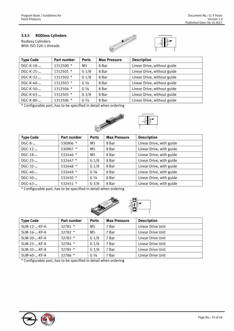
3.3.5 RODless Cylinders Rodless Cylinders With ISO 228-1 threads Type Code Part number Ports Max Pressure Description DGC-K-18-… 1312500 * M5 8 Bar Linear Drive, without guide
DGC-K-25-… 1312501 * G 1/8 8 Bar Linear Drive, without guide
DGC-K-32-… 1312502 * G 1/8 8 Bar Linear Drive, without guide
DGC-K-40-… 1312503 * G ¼ 8 Bar Linear Drive, without guide
DGC-K-50-… 1312504 * G ¼ 8 Bar Linear Drive, without guide
DGC-K-63-… 1312505 * G 3/8 8 Bar Linear Drive, without guide
DGC-K-80-… 1312506 * G ½ 8 Bar Linear Drive, without guide * Configurable part, has to be specified in detail when ordering Type Code Part number Ports Max Pressure Description DGC-8-… 530906 * M5 8 Bar Linear Drive, with guide
DGC-12-… 530907 * M5 8 Bar Linear Drive, with guide
DGC-18-… 532446 * M5 8 Bar Linear Drive, with guide
DGC-25-… 532447 * G 1/8 8 Bar Linear Drive, with guide
DGC-32-… 532448 * G 1/8 8 Bar Linear Drive, with guide
DGC-40-… 532449 * G ¼ 8 Bar Linear Drive, with guide
DGC-50-… 532450 * G ¼ 8 Bar Linear Drive, with guide
DGC-63-… 532451 * G 3/8 8 Bar Linear Drive, with guide * Configurable part, has to be specified in detail when ordering Type Code Part number Ports Max Pressure Description SLM-12-…-KF-A 32781 * M5 7 Bar Linear Drive Unit
SLM-16-…-KF-A 32782 * M5 7 Bar Linear Drive Unit
SLM-20-…-KF-A 32783 * G 1/8 7 Bar Linear Drive Unit
SLM-25-…-KF-A 32784 * G 1/8 7 Bar Linear Drive Unit
SLM-32-…-KF-A 32785 * G 1/8 7 Bar Linear Drive Unit
SLM-40-…-KF-A 32786 * G ¼ 7 Bar Linear Drive Unit * Configurable part, has to be specified in detail when ordering
Program Book / Guidelines for Festo Products
Document-No.: CL-F-Festo Version 1.0
Published Date: 06.10.2017
Page No.: 34 of 46
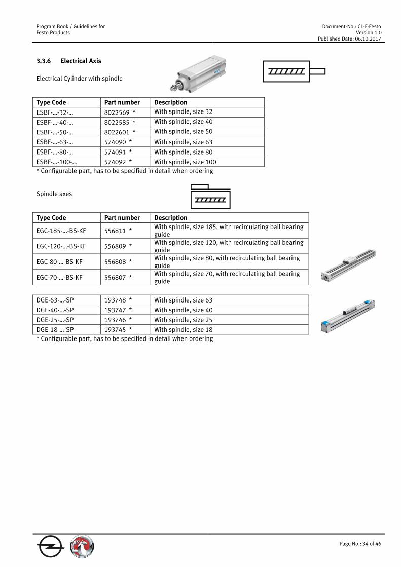
3.3.6 Electrical Axis Electrical Cylinder with spindle Type Code Part number Description ESBF-…-32-… 8022569 * With spindle, size 32 ESBF-…-40-… 8022585 * With spindle, size 40 ESBF-…-50-… 8022601 * With spindle, size 50 ESBF-…-63-… 574090 * With spindle, size 63
ESBF-…-80-… 574091 * With spindle, size 80
ESBF-…-100-... 574092 * With spindle, size 100 * Configurable part, has to be specified in detail when ordering Spindle axes Type Code Part number Description
EGC-185-…-BS-KF 556811 * With spindle, size 185, with recirculating ball bearing guide
EGC-120-…-BS-KF 556809 * With spindle, size 120, with recirculating ball bearing guide
EGC-80-…-BS-KF 556808 * With spindle, size 80, with recirculating ball bearing guide
EGC-70-…-BS-KF 556807 * With spindle, size 70, with recirculating ball bearing guide
DGE-63-…-SP 193748 * With spindle, size 63
DGE-40-…-SP 193747 * With spindle, size 40
DGE-25-…-SP 193746 * With spindle, size 25
DGE-18-…-SP 193745 * With spindle, size 18 * Configurable part, has to be specified in detail when ordering

Program Book / Guidelines for Festo Products
Document-No.: CL-F-Festo Version 1.0
Published Date: 06.10.2017
Page No.: 35 of 46
Toothed belt axes Type Code Part number Description
EGC-50-…-TB-KF 556812 * With toothed belt, size 50, with recirculating ball bearing guide
EGC-185-…-TB-KF 556817 * With toothed belt, size 185, with recirculating ball bearing guide
EGC-120-…-TB-KF 556815 * With toothed belt, size 120, with recirculating ball bearing guide
EGC-80-…-TB-KF 556814 * With toothed belt, size 80, with recirculating ball bearing guide
EGC-70-…-TB-KF 556813 * With toothed belt, size 70, with recirculating ball bearing guide
DGE-63-…-ZR 193744 * With toothed belt, size 63
DGE-40-…-ZR 193743 * With toothed belt, size 40
DGE-25-…-ZR 193742 * With toothed belt, size 25
DGE-18-…-ZR 193741 * With toothed belt, size 18
DGE-12-…-ZR 193740 * With toothed belt, size 12
DGE-8-…-ZR 193739 * With toothed belt, size 8
DGE-63-…-ZR-RF 534393 * With toothed belt, size 63, with roller guide
DGE-40-…-ZR-RF 534392 * With toothed belt, size 40, with roller guide
DGE-25-…-ZR-RF 534391 * With toothed belt, size 25, with roller guide * Configurable part, has to be specified in detail when ordering

Program Book / Guidelines for Festo Products
Document-No.: CL-F-Festo Version 1.0
Published Date: 06.10.2017
Page No.: 36 of 46
3.3.7 Rotary actuators With ISO 228-1 threads Type Code Part number Ports Max Pressure Description DSM-6-… all types * M3 8 Bar Swivel Module
DSM-8-… all types * M3 8 Bar Swivel Module
DSM-10-… all types * M3 8 Bar Swivel Module
DSM-12-… all types * M5 10 Bar Swivel Module
DSM-16-… all types * M5 10 Bar Swivel Module
DSM-25-… all types * M5 10 Bar Swivel Module
DSM-32-… all types * G 1/8 10 Bar Swivel Module
DSM-40-… all types * G 1/8 10 Bar Swivel Module
DSM-63-… all types * G ¼ 10 Bar Swivel Module * Configurable part, has to be specified in detail when ordering Type Code Part number Ports Max Pressure Description DRRD-12-… 574398 * M5 10 bar Semi-rotary Drive
DRRD-16-… 574399 * M5 10 bar Semi-rotary Drive
DRRD-20-… 574400 * M5 10 bar Semi-rotary Drive
DRRD-25-… 574401 * M5 10 bar Semi-rotary Drive
DRRD-32-… 574402 * G 1/8 10 bar Semi-rotary Drive
DRRD-35-... 574403 G 1/8 10 bar Semi-rotary Drive
DRRD-40-… 574404 * G 1/8 10 bar Semi-rotary Drive
DRRD-50-… 574405 * G ¼ 10 bar Semi-rotary Drive
DRRD-63-... 574407 G 3/8 10 bar Semi-rotary Drive * Configurable part, has to be specified in detail when ordering

Program Book / Guidelines for Festo Products
Document-No.: CL-F-Festo Version 1.0
Published Date: 06.10.2017
Page No.: 37 of 46
3.3.8 Guided Cylinders With ISO 228-1 threads Type Code Part number Ports Max Pressure Description DFM-12-… all types * M5 10 Bar Guide Cylinder
DFM-16-… all types * M5 10 Bar Guide Cylinder
DFM-20-… all types * M5 10 Bar Guide Cylinder
DFM-25-… all types * G 1/8 10 Bar Guide Cylinder
DFM-32-… all types * G 1/8 10 Bar Guide Cylinder
DFM-40-… all types * G 1/8 10 Bar Guide Cylinder
DFM-50-… all types * G ¼ 10 Bar Guide Cylinder
DFM-63-… all types * G ¼ 10 Bar Guide Cylinder
DFM-80-… all types * G 3/8 10 Bar Guide Cylinder
DFM-100-… all types * G 3/8 10 Bar Guide Cylinder * Configurable part, has to be specified in detail when ordering
3.3.9 Heavy duty stopper Cylinders With toggle lever With ISO 228-1 threads Type Code Part number Ports Max Pressure Description
DFST-50-30-DL-Y4-A 555573 G 1/8 10 Bar Stopper Cylinder, with toggle lever, without spring
DFST-50-30-D-Y4-A 543730 G 1/8 10 Bar Stopper Cylinder, with toggle lever, without spring
DFST-50-30-L-Y4-A 555572 G 1/8 10 Bar Stopper Cylinder, with toggle lever, with spring
DFST-50-30-Y4-A 543729 G 1/8 10 Bar Stopper Cylinder, with toggle lever, with spring
DFST-63-30-DL-Y4-A 555575 G 1/8 10 Bar Stopper Cylinder, with toggle lever, without spring
DFST-63-30-D-Y4-A 543745 G 1/8 10 Bar Stopper Cylinder, with toggle lever, without spring
DFST-63-30-L-Y4-A 555574 G 1/8 10 Bar Stopper Cylinder, with toggle lever, with spring
DFST-63-30-Y4-A 543744 G 1/8 10 Bar Stopper Cylinder, with toggle lever, with spring
DFST-80-40-DL-Y4-A 555577 G 1/8 10 B ar Stopper Cylinder, with toggle lever, without spring
DFST-80-40-D-Y4-A 543748 G 1/8 10 Bar Stopper Cylinder, with toggle lever, without spring
DFST-80-40-L-Y4-A 555576 G 1/8 10 Bar Stopper Cylinder, with toggle lever, with spring
DFST-80-40-Y4-A 543747 G 1/8 10 Bar Stopper Cylinder, with toggle lever, with spring
Program Book / Guidelines for Festo Products
Document-No.: CL-F-Festo Version 1.0
Published Date: 06.10.2017
Page No.: 38 of 46
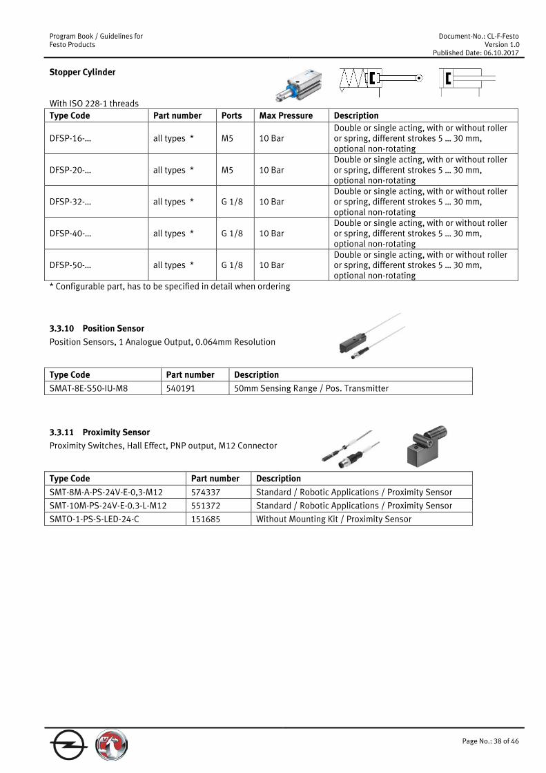
Stopper Cylinder With ISO 228-1 threads Type Code Part number Ports Max Pressure Description
DFSP-16-… all types * M5 10 Bar Double or single acting, with or without roller or spring, different strokes 5 … 30 mm, optional non-rotating
DFSP-20-… all types * M5 10 Bar Double or single acting, with or without roller or spring, different strokes 5 … 30 mm, optional non-rotating
DFSP-32-… all types * G 1/8 10 Bar Double or single acting, with or without roller or spring, different strokes 5 … 30 mm, optional non-rotating
DFSP-40-… all types * G 1/8 10 Bar Double or single acting, with or without roller or spring, different strokes 5 … 30 mm, optional non-rotating
DFSP-50-… all types * G 1/8 10 Bar Double or single acting, with or without roller or spring, different strokes 5 … 30 mm, optional non-rotating
* Configurable part, has to be specified in detail when ordering
3.3.10 Position Sensor Position Sensors, 1 Analogue Output, 0.064mm Resolution Type Code Part number Description SMAT-8E-S50-IU-M8 540191 50mm Sensing Range / Pos. Transmitter
3.3.11 Proximity Sensor Proximity Switches, Hall Effect, PNP output, M12 Connector Type Code Part number Description SMT-8M-A-PS-24V-E-0,3-M12 574337 Standard / Robotic Applications / Proximity Sensor
SMT-10M-PS-24V-E-0.3-L-M12 551372 Standard / Robotic Applications / Proximity Sensor
SMTO-1-PS-S-LED-24-C 151685 Without Mounting Kit / Proximity Sensor

Program Book / Guidelines for Festo Products
Document-No.: CL-F-Festo Version 1.0
Published Date: 06.10.2017
Page No.: 39 of 46
3.4 Directional control valves
3.4.1 ISO 15407-1 and ISO 15407-2 ISO 15407-1 Size 01 (26mm) Valves Type Code Part number Flow Rate Description VSVA-B-M52-MH-A1-1R5L 534556 1100 l/min Single Solenoid 5/2 / Solenoid Valve VSVA-B-B52-H-A1-1R5L ** 534557 1100 l/min Double Solenoid 5/2 / Solenoid Valve
VSVA-B-P53E-H-A1-1R5L 534560 1000 l/min Exhaust Centre 5/3 / Solenoid Valve
VSVA-B-P53U-H-A1-1R5L 534561 1000 l/min Pressure Centre 5/3 / Solenoid Valve
VSVA-B-T32C-AH-A1-1R5L 534552 900 l/min 2 Valves, 3/2 N.C. / Solenoid Valve
VSVA-B-T32U-AH-A1-1R5L 534553 900 l/min 2 Valves, 3/2 N.O. / Solenoid Valve
VSVA-B-T32H-AH-A1-1R5L 534554 900 l/min 2 Valves, (1) 3/2 N.O, (1) 3/2 N.C. / Solenoid Valve ** The use of 2 position valves in pneumatic systems shall require prior written approval from OPEL.
5/2 Single Sol 5/2 Double Sol 5/3 Exhaust Centre 5/3 Pressure Centre 2 x 3/2 Normally Closed 2 x 3/2 Normally Open 2 x 3/2 1 N.O. + 1 N.C.

Program Book / Guidelines for Festo Products
Document-No.: CL-F-Festo Version 1.0
Published Date: 06.10.2017
Page No.: 40 of 46
Sub Bases and Manifolds Type Code Part number Description
NAS-¼-01-VDMA 161109
Sub Base (26mm) Valves Individual Sub-Base
NAW-¼-01-VDMA 161102
Manifold (26mm) Valves Manifold Sub-Base
NEV-01-VDMA 161104
Manifold End Plates (26mm) End Plate Kit
NSC-1/2-01-VDMA 161105
Isolating disc for ports 1, 3, 5 (solenoid valves)
NDV-01-VDMA 161107
Blanking plate to seal spare or vacant valve positions
Sandwich Regulators * Type Code Part number Description VABF-S3-1-R1C2-C-6 543525 Port #1, 0.5 – 6 Bar / Regulator Plate
VABF-S3-1-R2C2-C-6 543533 Port #2, 0.5 – 6 Bar / Regulator Plate
VABF-S3-1-R3C2-C-6 543529 Port #4, 0.5 – 6 Bar / Regulator Plate
VABF-S3-1-R4C2-C-6 543537 Port #2 and #4, 0.5 – 6 Bar / Regulator Plate
QSP10-G1/8 565811 Adapter to use with standard gauges (see page 21, chapter 3.2.1), OPEL wants minimum diameter 40 gauges
* Required gauge must be purchased by machine builder separately (see chapter 3.2.1). Sandwich Flow Control Plate Type Code Part number Description VABF-S3-1-R1C2-C-6 543604 Port #2 and #4 flow control / Flow Control Plate
4 Port Regulator 2 Port Regulator
2 & 4 Port Regulator 1 Port Regulator

Program Book / Guidelines for Festo Products
Document-No.: CL-F-Festo Version 1.0
Published Date: 06.10.2017
Page No.: 41 of 46
ISO 15407-2 Size 01 (26mm) Valves Type Code Part number Flow Rate Description
VSVA-B-M52-MZH-A1-1T1L 8033045 1100 l/min Single Solenoid 5/2 / Solenoid Valve, with non-detending manual override
VSVA-B-B52-ZH-A1-1T1L ** 8033042 1100 l/min Double Solenoid 5/2 / Solenoid Valve, with non-detending manual override
VSVA-B-P53E-ZH-A1-1T1L 8033047 1000 l/min Exhaust Centre 5/3 / Solenoid Valve, with non-detending manual override
VSVA-B-P53U-ZH-A1-1T1L 8033046 1000 l/min Pressure Centre 5/3 / Solenoid Valve, with non-detending manual override
VSVA-B-T32C-AZH-A1-1T1L 8033036 900 l/min 2 Valves, 3/2 N.C. / Solenoid Valve, with non-detending manual override
VSVA-B-T32U-AZH-A1-1T1L 8033038 900 l/min 2 Valves, 3/2 N.O. / Solenoid Valve, with non-detending manual override
VSVA-B-T32H-AZH-A1-1T1L 8033040 900 l/min 2 Valves, (1) 3/2 N.O, (1) 3/2 N.C. / Solenoid Valve, with non-detending manual override
** The use of 2 position valves in pneumatic systems shall require prior written approval from OPEL.
5/2 Single Sol 5/2 Double Sol 5/3 Exhaust Centre 5/3 Pressure Centre 2 x 3/2 Normally Closed 2 x 3/2 Normally Open 2 x 3/2: 1 N.O. + 1 N.C. Electrical zone separator Type Code Part number Description
VABF-S6-1-E3C16-C-R3-SA 569126 Electrical zone separator with M12 plug, voltage 24VDC +/-10%, max. one per valve terminal, max. current 1A
Pin connection:

Program Book / Guidelines for Festo Products
Document-No.: CL-F-Festo Version 1.0
Published Date: 06.10.2017
Page No.: 42 of 46
Sub Bases and Manifolds Type Code Part number Description VABS-S4-1S-G14-B-R3 541069 Sub Base (26mm) Internal Pilot / Sub-Base
VABS-S4-1S-G14-R3 541063 Sub Base (26mm) External Pilot / Sub-Base
VABV-S4-1S-G14-2T2 539220 Manifold (26mm) Valves 4 Addresses / Manifold Sub-Base
VABE-S6-1R-G12 539234 Manifold End Plates Internal Pilot / End Plate
VABE-S6-1RZ-G12 539236 Manifold End Plates External Pilot / End Plate Sandwich Regulators * Type Code Part number Description VABF-S4-1-R1C2-C-6 540152 Port #1, 0.5 – 6 Bar / Regulator Plate
VABF-S4-1-R2C2-C-6 540160 Port #2, 0.5 – 6 Bar / Regulator Plate
VABF-S4-1-R3C2-C-6 540156 Port #4, 0.5 – 6 Bar / Regulator Plate
VABF-S4-1-R4C2-C-6 540164 Port #2 and #4, 0.5 – 6 Bar / Flow Control Plate
QSP10-G1/8 565811 Adapter to use with standard gauges (see chapter 3.2.1), OPEL wants minimum diameter 40 gauges
* Required gauge must be purchased by machine builder separately (see chapter 3.2.1). Sandwich Flow Control Plate Type Code Part number Description VABF-S4-1-F1B1-C 540175 Port #2 and #4 flow control
4 Port Regulator 2 Port Regulator
2 & 4 Port Regulator 1 Port Regulator

Program Book / Guidelines for Festo Products
Document-No.: CL-F-Festo Version 1.0
Published Date: 06.10.2017
Page No.: 43 of 46
3.4.2 Valve Terminal ISO 15407-2 Size 01 Fieldbus Manifold: 539217 VTSA-FB *
NOTE: Verify proper configuration by using Festo Online Configuration tool.
Fieldbus Electrical Order Code:
NOTE: All I/O blocks to be PNP version * Configurable part, has to be specified in detail when ordering
Program Book / Guidelines for Festo Products
Document-No.: CL-F-Festo Version 1.0
Published Date: 06.10.2017
Page No.: 44 of 46
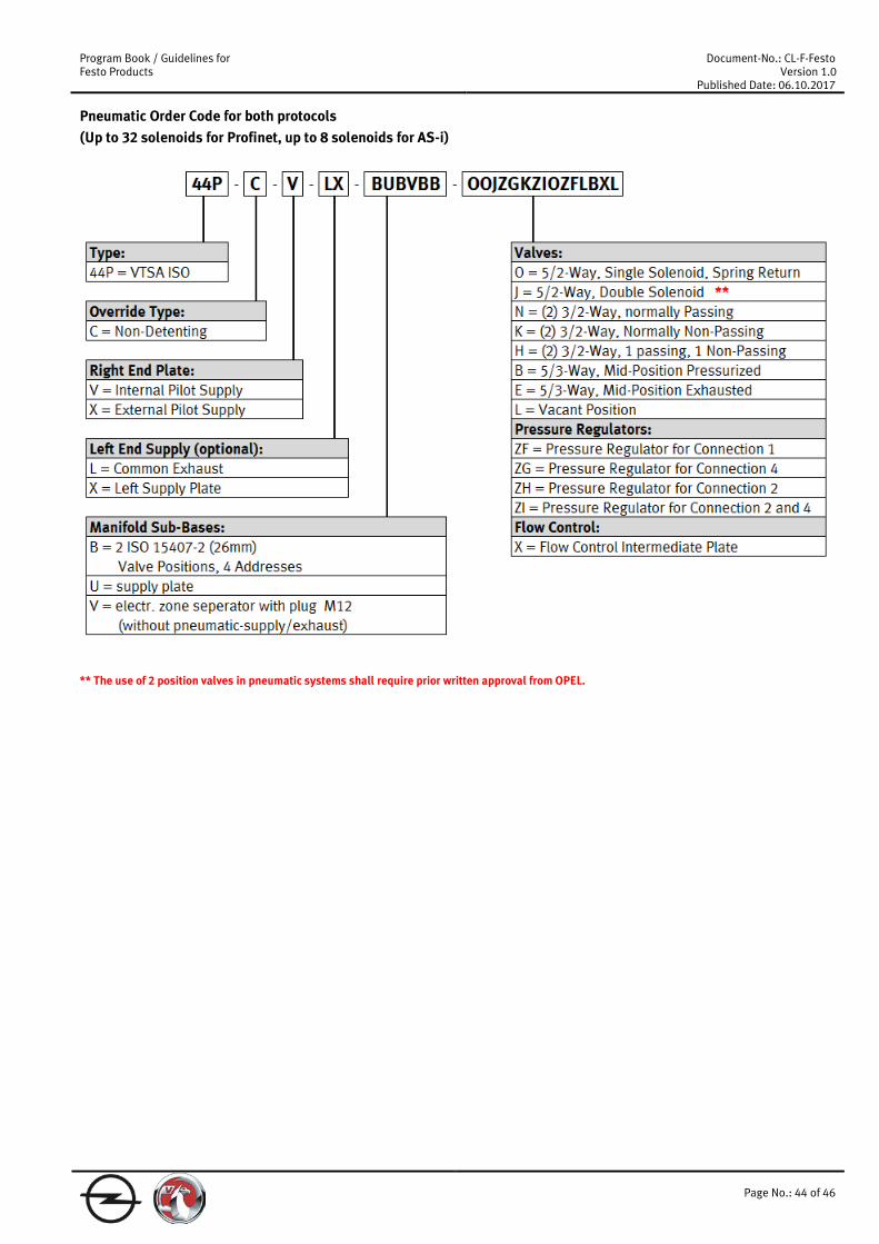
Pneumatic Order Code for both protocols (Up to 32 solenoids for Profinet, up to 8 solenoids for AS-i)
** The use of 2 position valves in pneumatic systems shall require prior written approval from OPEL.

Program Book / Guidelines for Festo Products
Document-No.: CL-F-Festo Version 1.0
Published Date: 06.10.2017
Page No.: 45 of 46
3.5 Safety applications
3.5.1 Safeguarding for pneumatic vertical axis Safeguarding for pneumatic vertical axis with two independents brake systems according to OPEL safety requirements with rod-lock (one channel design) and P.O. valves (two-channel safety design).
This circuit fulfils the safety requirements during power-on. dual (three) channels WV1 and WV2 (and WV5) are controlled by E-Stop-circuit.

Program Book / Guidelines for Festo Products
Document-No.: CL-F-Festo Version 1.0
Published Date: 06.10.2017
Page No.: 46 of 46
Each valve should be mounted on a separate sub-base. The mounting on manifold sub-bases or valve terminals is only allowed after approved deviation request from OPEL. The following has to be considered when using manifold sub-bases or valve terminals: Measures against common caused failures (CCF) have to be considered in applications above category 1 according ISO 13849-1. For pneumatic systems some adequate actions:
• Adherence to the air quality according the requirements of each product • Adherence to the permitted pressure range • Adherence to the permitted temperature range • Adherence to the permitted vibration and shock load • Adherence to the permitted electromagnetic compatibility (EMC)
Independent of the realization (valve terminal or single valves) this has to be considered. A FMEA shall be used to identify CCF and this results can be used to define measures against CCF. WV3, WV4, WV6 and WV7 shall be mounted direct on the cylinder ports or the connection between the cylinder and the valves WV3, WV4, WV6 and WV7 has to be realized with steel tubes. All things have to be done under the background of the hazard potential, in accordance with to the risk assessment. WV 3 and WV4 (leak free) have the identical functionality than P.O Check valves and can also be applied (see chapter 3.2.7). This circuit is added for power-off-conditions WV5 is controlled by power-on condition to open the rod-lock-device. In case of power-off the Cylinder is fixed by the circuit (WV1 – WV4) and WV5/rod-lock-device. dual channels. Instead of the rod-lock functionality direct on the Cylinder, it is also allowed to use a separate
- electrical brake (e.g. MAYR etc,) - pneumatic clamping device (e.g. SITEMA etc.)
Single sub-base Manifold sub-base Valve terminal
WV1 534559 VSVA-B-P53C-H-A1-1R5L ** 534559 VSVA-B-P53C-H-A1-1R5L **
8033048 VSVA-B-P53C-ZH-A1-1T1L ** (code “G” on valve terminal) on 161109 NAS-¼-01-VDMA on 161102 NAW-¼-01-VDMA
with 161104 NEV-01-VDMA
WV2 and WV5
534556 VSVA-B-M52-MH-A1-1R5L 534556 VSVA-B-M52-MH-A1-1R5L 8033045 VSVA-B-M52-MZH-A1-1T1L (code “O” on valve terminal)
on 161109 NAS-¼-01-VDMA with plug in 2 and 3 to change from function 5/2 to 3/2
on 161102 NAW-¼-01-VDMA with plug in 2 and 3 to change from function 5/2 to 3/2 and with 161104 NEV-01-VDMA
with plug in 2 and 3 to change from function 5/2 to 3/2
WV3 and WV4
25025 VL-2-¼-SA-3919 ** or see chapter 3.2.7
WV6 and WV7
See chapter 3.2.8 Manual pressure release valve for use with pilot operated check valves.
** Only approved for vertical axis!