chapter 1 · 2013-07-04 · chapter 1 introduction to optical tweezers: background, system designs,...
TRANSCRIPT

Chapter 1
Introduction to Optical Tweezers: Background,System Designs, and Commercial Solutions
Joost van Mameren, Gijs J.L. Wuite, and Iddo Heller
Abstract
Optical tweezers are a means to manipulate objects with light. With the technique, microscopically smallobjects can be held and steered while forces on the trapped objects can be accurately measured andexerted. Optical tweezers can typically obtain a nanometer spatial resolution, a piconewton force resolu-tion, and a millisecond time resolution, which make them excellently suited to study biological processesfrom the single-cell down to the single-molecule level. In this chapter, we provide an introduction on theuse of optical tweezers in single-molecule approaches. We introduce the basic principles and methodologyinvolved in optical trapping, force calibration, and force measurements. Next, we describe the compo-nents of an optical tweezers setup and their experimental relevance in single-molecule approaches. Finally,we provide a concise overview of commercial optical tweezers systems. Commercial systems are becomingincreasingly available and provide access to single-molecule optical tweezers experiments without the needfor a thorough background in physics.
Key words: Optical tweezers, Optical trap, Radiation pressure, Single molecule, Trap stiffnesscalibration, Force spectroscopy, Instrument design, Commercial optical tweezers, Molecular motors,DNA–protein interactions
1. Introduction
1.1. History of Optical
Tweezers
At the heart of optical tweezers techniques is the interactionbetween light and matter. The minute forces that are generatedin this interaction can be used to displace and trap microscopicobjects. In 1970, Ashkin laid the foundations for present-dayoptical tweezers techniques. At Bell labs, Ashkin observed thatmicron-sized latex spheres (beads) were attracted toward the cen-ter of an argon laser beam of a few mW power (1). It is thisattractive force that makes optical trapping possible. Ashkin alsoobserved, however, that the laser light scattered and propelled thebeads forward. By using two counterpropagating beams, he man-aged to avoid forward propulsion, and thus created the first stable
Erwin J.G. Peterman and Gijs J.L. Wuite (eds.), Single Molecule Analysis: Methods and Protocols,Methods in Molecular Biology, vol. 783, DOI 10.1007/978-1-61779-282-3_1, # Springer Science+Business Media, LLC 2011
1
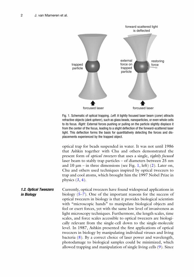
optical trap for beads suspended in water. It was not until 1986that Ashkin together with Chu and others demonstrated thepresent form of optical tweezers that uses a single, tightly focusedlaser beam to stably trap particles – of diameters between 25 nmand 10 mm – in three dimensions (see Fig. 1, left) (2). Later on,Chu and others used techniques inspired by optical tweezers totrap and cool atoms, which brought him the 1997 Nobel Prize inphysics (3, 4).
1.2. Optical Tweezers
in Biology
Currently, optical tweezers have found widespread applications inbiology (5–7). One of the important reasons for the success ofoptical tweezers in biology is that it provides biological scientistswith “microscopic hands” to manipulate biological objects andfeel or exert forces, yet with the same low level of invasiveness aslight microscopy techniques. Furthermore, the length scales, timescales, and force scales accessible to optical tweezers are biologi-cally relevant from the single-cell down to the single-moleculelevel. In 1987, Ashkin presented the first applications of opticaltweezers in biology by manipulating individual viruses and livingbacteria (8). By a correct choice of laser power and wavelength,photodamage to biological samples could be minimized, whichallowed trapping and manipulation of single living cells (9). Since
trappedparticle
restoringforce
external
forward scattered lightis deflected
forcused laserforcused laser
force ontrappedparticle
Fig. 1. Schematic of optical trapping. Left: A tightly focused laser beam (cone ) attractsrefractive objects (dark sphere ), such as glass beads, nanoparticles, or even whole cellsto its focus. Right : External forces pushing or pulling on the particle slightly displace itfrom the center of the focus, leading to a slight deflection of the forward-scattered laserlight. This deflection forms the basis for quantitatively detecting the forces and dis-placements experienced by the trapped object.
2 J. van Mameren et al.

the late 1980s, optical tweezers approaches have been extendeddown to the single-biomolecule level (10–20). In these single-molecule studies, the biomolecules of interest are not themselvestrapped directly, but are manipulated through optically trappedmicrobeads that act as handles and force transducers. A largefraction of this single-molecule work includes the study of theactivity of individual motor proteins (10, 14, 20). With opticaltweezers, the motion and forces generated by these motor pro-teins have been studied and controlled to reveal their dynamicsand energetics (Fig. 2, top). Another important area of researchincludes the study of biopolymers, such as DNA (7, 13, 16, 21).In these experiments, the DNA molecule is attached to one ormore optically trapped beads which allows stretching the moleculeand studying its mechanical properties through force spectroscopy(Fig. 2, bottom). In addition, this layout has been used to study-DNA–protein interactions (12, 15, 19, 22). A wide range ofDNA–protein interactions affect the structure of DNA, and thus
Fig. 2. Prototypical single-molecule optical tweezers assays. Top : A single kinesinmotor protein bound with its two heads to an optically trapped bead moves along asurface-immobilized microtubule track. Its 8-nm steps, the forces exerted, and themechanics of the stepping have been elucidated in such assays. Bottom: DNA sus-pended between two optically trapped beads.
1 Introduction to Optical Tweezers 3

the (force-dependent) length of the DNA molecules. In opticaltweezers, these length changes can be observed by measuring thedisplacements of the microbeads. Examples include the study ofDNA-binding proteins and the activity of DNA and RNA poly-merases.
With the advent of commercial optical tweezers systems inrecent years, this powerful single-molecule technique is approach-ing maturation and is becoming more and more accessible to awide range of biological scientists. As with the development ofcommercial fluorescence and AFM techniques, it is to be expectedthat commercial optical tweezers greatly contribute to our knowl-edge of biology on the single-molecule level. As a final motivationto read more about optical tweezers: in an interview with PhysicsToday, Nobel Prize winner Steven Chu said that he would notbe surprised if in the coming decennium another Nobel Prizewould be attributed to groundbreaking discoveries in molecularbiology facilitated by optical tweezers or other single-moleculetechniques (23).
2. Principles ofOptical TweezersTechniques
The basic physical principle underlying optical tweezers is theradiation pressure exerted by light when colliding with matter.For macroscopic objects, the radiation pressure exerted by com-mon light sources is orders of magnitude too small to have anymeasurable effect: we do not feel the light power of the sunpushing us away. However, for objects of microscopic dimensions(<100 mm), the radiation pressure of high-intensity light sourcesis sufficient to facilitate optical trapping.
2.1. Forces in an
Optical Trap
When photons enter an object that has a different refractive indexthan its surrounding medium, part of the momentum of thephotons can be transferred to this object. This transfer of momen-tum is the physical principle that underlies optical trapping (seeFig. 1, right). The forces exerted by photons on an opticallytrapped object can be divided into two components: the scatteringforce that pushes the object away from the light source and thegradient force that pulls the object toward the region of highestlight intensity. The correct physical description of optical trappingdepends on the size d of the trapped object in comparison to thewavelength l of the trapping light. In the regime d >> l, onespeaks of the “ray-optics” regime while the regime where d << lis called the Rayleigh regime. In biological experiments wheremicrometer-sized objects are trapped, the correct description isoften in between these two regimes such that neither description
4 J. van Mameren et al.

is quantitatively accurate. To provide a qualitative understandingof optical trapping, we here describe the forces in the more intui-tively interpretable ray-optics regime. In the ray-optics regime,the trapping force can be understood in terms of refraction oflight rays between media with different indices of refraction (24).Figure 3 qualitatively depicts the origin of the trapping forcesin this regime. The lateral gradient restoring force (Fig. 3a) canbe understood as follows. If rays p1 and p2 have different intensity,the momentum changes of these rays (Dp1 and Dp2, respectively)differ in magnitude, causing a net reaction force on the refractingmedium in the direction of highest intensity. The x-projection ofthis force, Dpx, tends to counteract a displacement from the laserbeam axis, pulling the particle toward the center of the beam. Theaxial gradient force is similarly caused by momentum transferupon refraction, resulting in a restoring force toward the focus,as in Fig. 3b. The scattering force (not depicted) would cause theobject to be propelled out of the focus, along the positive z-direction. The object is stably trapped only if the scattering forcealong the positive z-direction is compensated by the gradient forcealong the negative z-direction. To achieve this, a significant frac-tion of the incident light should come in at large angles, calling fora tightly focused trapping light source typically obtained by usinga microscope objective.
2.2. Trap Stiffness An optical trap forms a three-dimensional potential well for thetrapped particle. The particle experiences an attractive force
p2'
p2'
p1'
p1'
p2p1
dp1
lateral trapping force axial trapping force
dp2
–dp1–dp2
dpx
a
dpz
–dp1 –dp2
b
p2p1
dp2 dp1
Fig. 3. Forces on an optically trapped particle in the ray-optics regime. (a) Lateral gradient force of a Gaussian laser beamprofile. (b) Axial gradient force toward the focus of the trapping light. The white arrows indicate the net restoring force.Note that the scattering component due to reflection by the particle is not indicated.
1 Introduction to Optical Tweezers 5

toward the potential minimum, which is located at a stable posi-tion where the trapped particle experiences no net force. Close tothe potential minimum, the trap can be approximated to beharmonic, e.g., the attractive force F is directly proportional tothe displacement x of the particle according to Hooke’s law:F ¼ �kx. Here, the spring constant k has units [N/m] like amechanical spring and represents the stiffness of the optical trap.Knowledge of the trap stiffness allows accurate quantification ofthe external forces acting on a trapped particle from a measurementof the particle’s displacement. The trap stiffness, however, is acomplex function of the intensity profile and wavelength of thelaser, the shape and size of the particle, the indices of refraction,and other parameters and is difficult to calculate from first princi-ples. Therefore, the trap stiffness is commonly determined byperforming calibration experiments. Using a laser of 1 W, thetypical trap stiffness that can be obtained in a single-beam opticaltrap is in the order of 100 pN/mm.
2.3. Principles of Trap
Calibration
To allow quantitative measurement of the forces on opticallytrapped particles, several calibration methods to measure thetrap stiffness have been developed.
Drag force calibration: The simplest way to calibrate an opticaltrap is to apply an external force of knownmagnitude and measurethe displacement of the trapped particle. The external force istypically generated by inducing a fluid flow. The drag force by afluid (viscosity �, flow velocity v) on a spherical bead of diameter dis given by Stokes’ law: F ¼ gv, where g is the drag coefficientg ¼ 3p�d. The fluid drag displaces the bead from the center of thetrap until the drag force is opposite and equal to the restoringforce from the optical trap, which yields k ¼ gv=x. The trap stiff-ness can, thus, be obtained by measuring the displacement, x, ofa bead of known size due to the fluid flow of a liquid with knownviscosity and velocity.
Brownian motion calibration: Another, more accurate calibrationprocedure is based on the Brownian motion of a bead in an opticaltrap, caused by the continuous and random collisions with solventmolecules. The stiffness of an optical trap can be calibrated byrecording the power spectrum of the displacement fluctuations ofa trapped bead of known size, as shown in Fig. 4. The powerspectrum Sx(f) describes how the power of these displacementfluctuations is distributed in frequency f and is found to have aLorentzian shape (25, 26):
Sxðf Þ ¼ kBT
gp2 fc2 þ f 2
� � ;where kBT is the available thermal energy. The power spectrumexhibits a characteristic corner frequency fc � k=2pg, which is
6 J. van Mameren et al.

proportional to the trap stiffness. Figure 4 shows that at lowfrequencies f << fc, the power spectrum is roughly constant,
Sxðf Þ ¼ Sx;0 ¼ 4gkBT k2�
. At high frequencies f >> fc, however,
the power spectrum falls off like 1/f 2, which is characteristic offree diffusion. The inverse of the corner frequency represents thetime response of the optical trap, which is typically in the order of1–0.1 ms. For shorter timescales, the particle does not “feel” theconfinement of the trap which means that behavior of biologicalsystems at timescales more rapid than this response time cannotbe detected by the optical tweezers. The two power spectra ofFig. 4, acquired at two different trap stiffnesses, illustrate thatwhen higher trap stiffnesses are used (i.e., by increasing the laserpower), the bead fluctuations at low frequencies are reduced andthe time response of the optical trap increases. On the other hand,a higher trap stiffness implies smaller bead displacement at a givenforce which means that more accurate bead displacement detec-tion is required to obtain the same force sensitivity.
It is important to note that, in practice, the detector used todetermine the bead position reads uncalibrated displacementfluctuations u(t) (i.e., as some voltage rather than as a displacement
10 100
frequency [Hz]
pow
er s
pect
rum
[V2
Hz–
1 ]
100010–9
10–8
10–7
10–6
10–5
10–4
10–3
fc (3W)
fc (6W)
2
Fig. 4. Power spectra representative of the positional fluctuations of a particle trapped atdifferent laser powers. A 1-mm diameter polystyrene bead is held in an optical trap whilethe displacement signal in volts is sampled at 195 kHz. The graph shows power spectraof the displacement signal at 3 W (dark gray ) and at 6 W (light gray ) laser power. Boththe downward shift of the low-frequency plateau S0 and the upward shift of the cornerfrequency fc (see arrows at 250 and 650 Hz, obtained from Lorentzian fits) for the stiffer6 W trap can clearly be observed.
1 Introduction to Optical Tweezers 7

in nanometers). The response of the detector R, which has unitsm/V, relates the displacement to u(t) as x(t) ¼ Ru(t). To fullycalibrate an optical trap, the power spectrum of the uncalibrateddisplacement fluctuations Su(f) is fitted with a Lorentzian:
Suðf Þ ¼ Su; 0fc2
ðfc2 þ f 2Þ :
Once the parameters Su;0 and fc are obtained, the trap stiffnesscan be calculated using
k ¼ 2kBT
pSu;0fcor k ¼ 2pgfc;
and, providing the bead diameter and solvent viscosity are known,the detector response can be calculated using
R ¼ kBT
p2gSu;0fc2
" #1=2
¼25�C 5:0� 10�20m3=s
Su;0fc2d
" #1=2
:
Finally, to convert uncalibrated displacement data to forces,the displacement signal should be multiplied by R and the trapstiffness such that F ¼ kx ¼ kRu.
3. OpticalTweezers Systems
An optical tweezers setup consists of various dedicated compo-nents. In this section, we discuss the role of these components inoptical tweezers function and performance. Below, we divide anddiscuss the components in five groups: the trap, the environmentof the trap, trap steering, position and force detection, and theenvironment of the setup. In addition, we also discuss the abilityto combine optical tweezers with other techniques and the differ-ent optical trapping assays that are typically used in biologicalexperimentation. For illustration, Fig. 5 shows the schematiclayout of an optical tweezers setup that combines two steerableoptical traps with fluorescence microscopy.
3.1. The Optical Trap At the heart of every single-beam optical tweezers instrument isthemicroscope objective, which creates a tight focus to form a stableoptical trap. Tight focusing implies that a significant fraction ofthe incident light comes in at large angles such that the scatteringforce is overcome by the gradient force. The maximum incidenceangle of the light Ymax is determined by the numerical aperture(NA) of the objective used to focus the laser beam. This is ameasure for the solid angle over which the objective lens can
8 J. van Mameren et al.

gather light and is defined as: NA ¼ n sin Ymax, where n is therefractive index of the immersion medium (i.e., the mediumbetween the objective lens and the sample) and Ymax is one-halfthe angular aperture. The value of n varies between 1.0 for air and�1.5 for most immersion oils. For typical oil-immersion objec-tives, an NA of 1.4 corresponds to a total acceptance angle of theobjective of about 130�. To obtain a stable three-dimensionaloptical trap, the laser beam entering the objective has to be wideenough to fill or overfill the back aperture of the objective. Thisway, one provides sufficient convergent, high-angle rays that con-tribute to counteracting the scattering force.
Themaximum forces that can be exerted by an optical trap canbe enhanced by either increasing the laser power or optimizing thequality of the focal spot of the laser and the refraction of the laserby the trapped particle (i.e., choosing the proper optics and mate-rials with proper optical densities; see below). The laser power canbe increased only up to a certain limit, above which more laserlight would lead to heating or photodamage of the examinedsystem (often delicate biomaterials) or even of the optics in theinstrument (27). Therefore, care must be taken to optimize thequality of the focal spot of the trapping laser. The difference inrefractive index of the trapped object n2 compared to that of the
InGaAs
InGaAs
InGaAsQPD (x,y)
signalattenuation
laser
isolator
moving powercontrol
mainshutter
shutters
TRAP 2
1P
AR
T
OPTICAL MICROSCOPE TRAP STEERING LASER
Fig. 5. Optics layout of a typical optical tweezers instrument. The various parts of the system as described in the text arebounded by dashed boxes. The depicted layout was adopted from that of the “NanoTracker” commercial optical tweezersplatform of JPK Instruments (see Subheading 5).
1 Introduction to Optical Tweezers 9

surrounding medium n1 determines how strongly the incidentrays are refracted and, consequently, how strong the trappingforce is. The required balance between gradient and scatteringforces yields an optimal refractive index of n2 ¼ 1.69 (5). Oneoften uses silica (glass) particles (n2 ¼ 1.37–1.47) or polystyreneparticles (n2 ¼ 1.57). The trapping forces that can be obtainedfor polystyrene particles are, thus, higher. When using an oil-immersion objective, the refractive index of the immersion oilmatches both that of the objective lens and that of the glass ofthe sample. Therefore, the maximum NA can be achieved withoil-immersion objectives. However, due to the refractive indexmismatch between the sample glass and the buffer, spherical aber-rations deteriorate the quality of the laser focus when the distanceof the focus to the sample surface increases (optical trapping inwater with oil-immersion objectives is typically performed withinseveral tens of micrometers of the glass surface) (28). To allowequally stable trapping at any distance to the surface, water-immersion objectives are often used. Despite the fact that theNA is somewhat compromised (typically, NA ¼ 1.2 for water-immersion objectives), the ability to move away from the samplesurface without lowering the trap quality can be a good reason touse water-immersion objectives.
For optical trapping, single-mode continuous wave laserswith a Gaussian beam profile (i.e., operated in the lowest,TEM00, mode) are commonly used. The laser power typicallyranges from a few hundred milliwatts up to several watts. Impor-tant properties of the laser for stable trapping are low intensityfluctuations and high pointing stability (little angular and trans-verse wandering of the beam). Of particular interest for biologicalexperiments is the wavelength. Since the light intensity at thefocus is very high, heating and damage through light absorptionby the often delicate biological material need to be considered.Near-infrared lasers (800–1,200 nm, most often the 1,064-nmline from diode-pumped solid-state lasers) are typically usedbecause of the low absorption of biological material as well aswater in this spectral range (5).
Although in current biological applications optical traps aremost commonly formed by tightly focusing a single laser beam(2), the first stable optical trap was accomplished in 1970 by usingtwo counterpropagating focused laser beams (1). The counter-propagating layout does not require tight focusing such that lowNA (<1) objectives or no objective at all may be used. Advanta-geously, this allows for a larger working distance and lower locallight intensity at the trap, making it useful to handle living cells.The “optical stretcher,” designed to probe the deformability ofindividual cells, is a key example of this approach (29).
10 J. van Mameren et al.

3.2. Environment
of the Trap
Microfluidics: To ascertain well-controlled experimental condi-tions in single-molecule experiments, it is often useful – if notrequired – to implement a way to bring the biochemical “ingre-dients” together under the microscope. The use of microfluidicsallows for a fine control over this process by fluid flow of minutevolumes of the solutions used. In addition, microfluidic controlallows for drag force calibration of the trap, as well as flow stretch-ing of biopolymers, such as DNA (30). An alternative way toinduce viscous drag is by moving the fluid reservoir with respectto the trap using a motorized microscope stage. Particularly usefulis the combination of either a motorized or a piezoelectric stagewith a laminar flow cell. The laminar flow ensures that differentbuffer flows can be in contact with each other with minimal buffermixing. By moving the stage to change the position of the trappedbeads in the microfluidic device, the buffer conditions can berapidly exchanged between the regions of different buffer flow.Recently, Brewer et al. extensively reviewed the use of microflui-dics devices in single-molecule experiments (31).
Temperature control: In biological experiments, temperature oftenplays an important role. As in conventional microscopy, tempera-ture-controlled fluidics, stages, and objectives can be used tocontrol the temperature at which biological processes take place.In optical tweezers experiments, temperature control of the objec-tive is, in particular, considered. Objectives with short focallengths, required to obtain a tight focus, are necessarily in closecontact with the trapping region through the immersion mediumand act as an effective heat sink. Moreover, apart from the rele-vance for the temperature of the biological system, temperaturecontrol of the objective can be beneficial for the performance ofthe optical tweezers as well. The high laser intensities in opticaltrapping may produce heating of the optical components, thuscausing optical drift, increased stabilization time, and/ordecreased spatial resolution. A millikelvin temperature-stabilizedobjective has been employed to obtain base pair resolution inoptical tweezers experiments on DNA (32). Finally, judiciousdesign and analysis of the experiment are required when largetemperature fluctuations are anticipated. Among other issues,the reliability of (real time) calibration of optical tweezers usingBrownian fluctuations is impacted by significant temperaturefluctuations.
3.3. Position and Force
Detection
The key to quantitative optical trapping is the accurate detection ofthe position of the particle in an optical trap. Within the volume ofthe laser focus, the displacement of the particle from its equilibriumposition is directly proportional to the forces acting on this particle.
1 Introduction to Optical Tweezers 11

Several techniques have been developed for sensitive positiondetection which are discussed below.
Lateral position and force detection – The simplest position-detec-tion scheme relies on video-based imaging of a bead in the opticaltrap. Using centroid-tracking or template-matching algorithms,the position of one or multiple beads can be obtained with sub-pixel resolution (down to several nanometers) either by off-line oronline digital video analysis (33, 34). Although video-based posi-tion detection is simple and direct, it is limited in time resolutionby the video acquisition rate (from typically 25 up to 100 Hz withfaster cameras). More dedicated imaging techniques, where onebead is directly imaged on a position-sensitive detector (PSD) orquadrant photodiode (QPD), provide a higher time resolution,but require high magnifications and are thus limited in range andsignal-to-noise ratio (35, 36). Besides allowing the calculation ofthe active forces in a biological system when the trap stiffness isknown, imaging also provides spatial information on the studiedsystem; observation of the absolute position of beads in the cam-era’s field of view can provide information on the length scale of abiological system, such as a stretched biopolymer between twobeads or the motion of a molecular motor through the field ofview, independent of the optical trapping (cf. Fig. 2).
The highest time resolution (~ms) and spatial resolution(~pm) are currently obtained with laser-based interferometrytechniques for position detection. Currently, the most commonposition-detection scheme is back-focal-plane (BFP) interferome-try (37, 38). Here, the interference between unscattered andforward-scattered light of a laser beam focused on a bead is usedto provide positional information in the two lateral dimensions.By imaging the intensity distribution in the BFP of a condenserlens on a QPD or PSD, the recorded signals are rendered insensi-tive to the location of the trap in the field of view. A majoradvantage of these interference techniques is that the trappinglaser can be used to perform trapping and position detectionsimultaneously. In this situation, the detection and trap are intrin-sically aligned and only relative displacements of the bead withrespect to the trap are measured. Displacements of typically up to afew hundred nanometers away from the center of the optical trapare directly proportional to the measured shift on the photodiodesin this configuration. On top of this, simultaneous video analysisof optical images can still be used to measure absolute positionsand distances in the studied system.
Axial position detection – True three-dimensional position detec-tion allows tracking the (suppressed) Brownian motion ofthe trapped particle and, thereby, fully quantifying the forces feltby the object in the optical trap. This can be accomplished bycombining axial position detection with the abovementioned
12 J. van Mameren et al.

lateral position-detection techniques. The axial position oftrapped particles has been detected by using fluorescence meth-ods, performing template-based analysis of bead images (as isoften done in magnetic tweezers experiments, see Chapter 15),measuring the forward-scattered light intensity, or using nonima-ging interference methods (6). The nonimaging axial interferencemethod, in which modulations in the total laser intensity aredetected in the BFP of the condenser, is most practical since itis accurate as well as easily combined with lateral interference-based detection. Contrary to lateral detection, the best axialsensitivity is obtained when only the low-NA fraction of thelight is detected (39).
3.4. Trap Steering If microscope stage movements do not provide enough flexibilityto manipulate trapped objects, the trapping beam itself can besteered through the sample. This is particularly useful for steeringmultiple traps. Lateral trap movement can be achieved by chang-ing the incoming angle of the trapping beam into the objectivewhile axial movement is effected by changing the level of collima-tion of the beam.
In practice, such three-dimensional trap steering can beaccomplished by moving the lenses in a telescope in front of theobjective. Alternatively, the use of tip-tilt or galvanometric mir-rors, for which accurate and reproducible positioning can beobtained through closed-loop feedback systems, allows rapid lat-eral trap movement up to several kHz. Finally, more advancedtechniques for trap steering include acousto-optical deflectors(AODs) and electro-optical deflectors (EODs). These providehigher scanning speeds up to the MHz range, but typically havemore limited deflection ranges. Additional drawbacks are thelower throughput efficiency and inhomogeneous diffraction ofAODs and the high costs of EODs.
To avoid nonlinearities in the lateral trap steering, it is impor-tant to place the steering elements in the setup such that theangular deflection from the optical axis originates in planes conju-gate to the BFP of the objective, such as the telescope configura-tion in Fig. 6. Otherwise, the transmitted laser power and,therefore, the trap stiffness will be dependent on the position inthe sample. Finally, it is important to realize that trapped objectsare limited in manipulation speed. Viscous drag causes the trappedparticle to escape from the trap at high steering speeds.
If scanned across multiple positions, galvanometric mirrorsand the even faster AODs or EODs can be used to generate multi-ple traps from a single laser source (see Fig. 7). If the laser is scannedrapidly enough, a trapped particle may not sense the transientabsence of the optical trap when at the other scanned positions.This way of generating multiple traps is called trap multiplexingor “time sharing.” An alternative approach to generate multiple
1 Introduction to Optical Tweezers 13

traps from a single laser line is provided by diffractive opticalelements, such as spatial light modulators (SLMs). Multiple trapgeneration and steering in this case rely on the holographic patternthat causes the incident laser to diffract into separate foci in thesample. The intricate computation of the holographic patternpractically limits the update rates with which the traps can besteered, although this technique is continuously improved. So far,holographic schemes based on SLMs have proven difficult to com-bine with position- and force-sensing schemes.
3.5. Environment
of the Setup
To ensure stability and high spatial resolution, the environment ofthe optical tweezers setup needs to be well-controlled. Common
Fig. 7. Microscopy image of the time-shared optical trapping of 42 beads using AODs.This image demonstrates the smallest game of Tetris ever played. The correspondingvideo can be found online at http://www.nat.vu.nl/compl/dualdna/tetris.
objectiveTL1 TL2
BFPf1
so si
f2
Fig. 6. Steering of an optical trap using a telescope configuration. The second telescopelens (TL2) images the plane of the first one (TL1) onto the back focal plane (BFP) of theobjective: 1/si ¼ 1/f2 � 1/(f1 + f2). Lateral movement of the first telescope lenscauses the incident collimated laser beam to enter the BFP under an angle. The laserfocus in the sample, thereby, displaces laterally. No intensity changes occur whendisplacing the beam, hence keeping the trap stiffness position independent.
14 J. van Mameren et al.

precautions include the use of passively damping optical tables andtemperature stabilization within 0.5–0.1 K. Convection of the airin the optical pathway can induce beam deviations through localdensity fluctuations. These effects can be minimized by enclosingthe optical path, reducing the optical path length, or reducingthe number of foci along the optical path, since the beam is moresensitive to local density fluctuations in these focal points. Forthe most demanding applications, optical tweezers instrumentshave been placed in acoustically isolated rooms with air condition-ing equipment that filters out dust particles in the air or even inenclosures in which ambient air is replaced by helium, the evenlower refractive index of which renders the instruments less sus-ceptible to density fluctuations of the gas (40).
3.6. Combining Optical
Tweezers with Other
Techniques
Optical tweezers instruments are composed of common micros-copy components and are often incorporated into commercialmicroscopes. This makes it attractive to combine optical tweezers,and their high level of control, with the capabilities of otheroptical techniques in order to study biological systems in greaterdetail. The design of an optical tweezers instrument, however,directly influences its capabilities and to what extent other micros-copy or related techniques can be integrated with it.
The counterpropagating beams layout, for instance, requirescritical coaxial alignment, is difficult to implement in conventionalmicroscopes, and puts strong restrictions on the optics and addi-tional functionalities of the experimental setup. A single-beamoptical trap, on the other hand, requires a tightly focused laserbeam for stable trapping, which in turn requires a high-NA objec-tive lens and a suitably expanded laser beam at the input aperture.Other than that, no strong requirements are imposed on themicroscope, which renders the single-beam trap the more widelyused configuration.
A new development is the integration of sensitive fluorescencemicroscopy with optical tweezers, as recently reviewed (30). Thedirect visualization of single molecules in controlled optical twee-zers manipulation experiments has proven a powerful method forthe detailed investigation of biomolecular systems, in particularfor unraveling DNA–protein interactions (30, 41, 42). In theseexperiments, DNA is manipulated with optical tweezers while thebinding and activity of proteins that interact with the DNA aredirectly observed through fluorescence microscopy. Changes inDNA structure due to DNA–protein interactions or movement ofproteins along DNA can, thus, be simultaneously studied withforce spectroscopy and fluorescence microscopy, providing a highlevel of versatility and unambiguity in these experiments. Further-more, other advanced optical microscopy techniques, such aspolarization or Raman spectroscopy, have been fruitfully com-bined with optical tweezers (43–46).
1 Introduction to Optical Tweezers 15

3.7. Optical Trapping
Assays Employed
in Biology
Several experimental layouts have been developed to employ opti-cal tweezers in biology. The simplest layout consists of a singleoptical trap, in which particles can be manipulated and, optionally,forces between the trapped particle and its surroundings can bemeasured. A single optical trap has, for instance, been used toperform force spectroscopy on biomolecular systems that aretethered between the trap and a fixed substrate (see Fig. 2, top).Examples of experiments using this geometry include measure-ments of the mechanical and structural properties of biopolymerstethered between a trapped bead and a fixed substrate (i.e., a glassslide or a bead held by a micropipette (15)) and measurements ofthe forces involved in biomolecular activity (10, 20). This activitycan be observed either directly, such as in the motion of motorproteins tethered to a trapped bead, or indirectly by measuringstructural changes in biomolecules, such as DNA, due to enzy-matic activity.
The fixed substrate can also be replaced by a particle trappedin a second optical trap (see Fig. 2, bottom). In this dual-trap assay,a biomolecular system tethered between two trapped beads can,thus, be fully suspended in solution, which prevents unwantedsurface interactions. In addition, this layout suppresses noise asso-ciated with fluctuations or drift in the relative positions of theoptical trap and a fixed substrate. This geometry has beenemployed to obtain single base pair resolution of RNA polymeraseactivity (40).
Finally, advanced optical trapping geometries include the useof multiple optical traps (see Fig. 7), which allow manipulatinglarge biological structures and multiple colloidal particles(47–50). On the single-molecule level, multiple optical trapshave been used to measure interactions of multiple DNA mole-cules and bound proteins (22, 51).
4. CommercialOptical TweezersSystems
The design and construction of an optical tweezers instrumentcan be a tedious task, requiring practical and theoretical experi-ence in fields ranging from laser physics, optics, thermodynamics,hydrodynamics, and analog and digital electronics to computerscience in order to allow some level of computer control of theinstrument as well as data acquisition. In addition, the mainte-nance of a home-built instrument can be time consuming as well.In view of that, it needs little explanation that many life scienceresearchers hesitate to switch to this type of experimentation.
During the past decade, several companies have started offer-ing commercial solutions for optical trapping experiments (23).
16 J. van Mameren et al.
These solutions range from do-it-yourself kits, like that fromThorlabs or the miniTweezers from the Bustamante lab (seehttp://tweezerslab.unipr.it), to fully automated turnkey plat-forms. Recently, a product review appeared that describes andcompares most commercial platforms (52). The review and thecomparison chart therein make clear that optical tweezers tech-nology has ripened over the past decades. Most manufacturersprovide instruments that can be flexibly attached or integratedinto a standard research-grade inverted optical microscope.Depending on the details of the instrument, this may leave openthe possibility to configure the optical microscope in order tocombine optical tweezers with other microscope techniques,as described above. However, when the optical trapping laser iscoupled into the microscope through the fluorescence port, it isobviously difficult or impossible to combine optical tweezers andfluorescence microscopy.
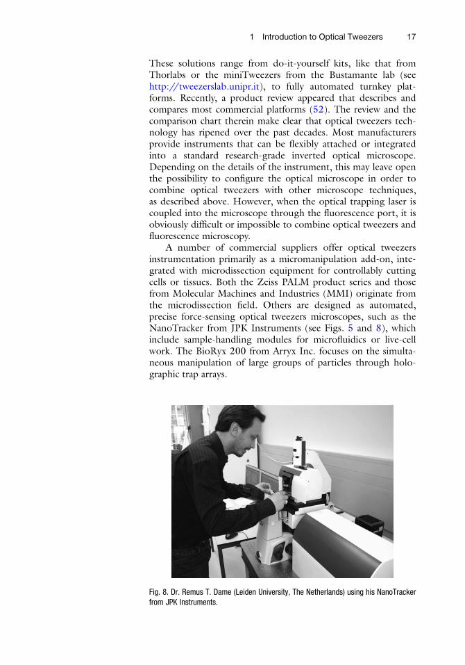
A number of commercial suppliers offer optical tweezersinstrumentation primarily as a micromanipulation add-on, inte-grated with microdissection equipment for controllably cuttingcells or tissues. Both the Zeiss PALM product series and thosefrom Molecular Machines and Industries (MMI) originate fromthe microdissection field. Others are designed as automated,precise force-sensing optical tweezers microscopes, such as theNanoTracker from JPK Instruments (see Figs. 5 and 8), whichinclude sample-handling modules for microfluidics or live-cellwork. The BioRyx 200 from Arryx Inc. focuses on the simulta-neous manipulation of large groups of particles through holo-graphic trap arrays.
Fig. 8. Dr. Remus T. Dame (Leiden University, The Netherlands) using his NanoTrackerfrom JPK Instruments.
1 Introduction to Optical Tweezers 17

When considering the purchase of a commercial optical twee-zers instrument, the aforementioned review may be a good start-ing point. Several aspects should be kept in mind. Obviously, thefirst thing to define is the main application for the instrument.Is the system going to be used only for manipulation, or isquantification of the forces exerted going to be useful? Is fluores-cence imaging required, or are other microscope features impor-tant? Is the delivered software flexible enough to accommodatethe required experiments? Important characteristics, like userfriendliness or flexibility in system design, are best assessed in alive demonstration of the instrument.
5. ConcludingRemarks
Optical tweezers techniques form a valuable addition to thesingle-molecule toolkit. These minimally invasive techniques pro-vide scientists with the ability to actively manipulate biomoleculeswith nanometer precision and to measure or apply forces withpiconewton resolution. Examples of the application of thesepowerful tools in molecular biology include the study of activemolecular motors, the mechanical properties of DNA, andthe mechanochemistry of DNA–protein interactions. Commercialoptical tweezers systems are becoming increasingly available,which makes this powerful and versatile technique accessible to abroad range of researchers from different backgrounds andundoubtedly drives new biological discoveries on the single-molecule level. The following chapters describe detailed methodsand protocols of several applications of optical tweezers in molec-ular biology.
References
1. Ashkin, A. (1970) Acceleration and Trappingof Particles by Radiation Pressure PhysicalReview Letters 24, 156–9.
2. Ashkin, A., Dziedzic, J. M., Bjorkholm, J. E.,and Chu, S. (1986) Observation of asingle-beam gradient force optical trapfor dielectric particles Optics Letters 11,288–90.
3. Chu, S. (1991) Laser manipulation of atomsand particles Science 253, 861–6.
4. Chu, S. (1992) Laser trapping of neutral par-ticles Scientific American 266, 70–6.
5. Svoboda, K., and Block, S. M. (1994)Biological Applications of Optical ForcesAnnual Review of Biophysics & BiomolecularStructure 23, 247–85.
6. Neuman, K. C., and Block, S. M. (2004)Optical trapping Review of Scientific Instru-ments 75, 2787–809.
7. Moffitt, J. R., Chemla, Y. R., Smith, S. B., andBustamante, C. (2008) Recent Advances inOptical Tweezers Annual Review of Biochem-istry 77, 205–28.
8. Ashkin, A., and Dziedzic, J. M. (1987) Opticaltrapping and manipulation of viruses and bac-teria Science 235, 1517–20.
9. Ashkin, A., Dziedzic, J. M., and Yamane, T.(1987) Optical trapping and manipulation ofsingle cells using infrared-laser beams Nature330, 769–71.
10. Block, S. M., Goldstein, L. S. B., and Schnapp,B. J. (1990) Bead Movement by Single
18 J. van Mameren et al.

Kinesin Molecules Studied with OpticalTweezers Nature 348, 348–52.
11. Bustamante, C., Macosko, J. C., andWuite, G.J. L. (2000) Grabbing the cat by the tail:Manipulating molecules one by one NatureReviews Molecular Cell Biology 1, 130–6.
12. Davenport, R. J., Wuite, G. J. L., Landick, R.,and Bustamante, C. (2000) Single-moleculestudy of transcriptional pausing and arrest byE. coli RNA polymerase Science 287,2497–500.
13. Smith, S. B., Cui, Y., and Bustamante, C.(1996) Overstretching B-DNA: the elasticresponse of individual double-stranded andsingle-stranded DNA molecules Science 271,795–9.
14. Svoboda, K., Schmidt, C. F., Schnapp, B. J.,and Block, S.M. (1993) Direct Observation ofKinesin Stepping by Optical Trapping Inter-ferometry Nature 365, 721–7.
15. Wuite, G. J. L., Smith, S. B., Young, M., Kel-ler, D., and Bustamante, C. (2000) Single-molecule studies of the effect of template ten-sion on T7 DNA polymerase activity Nature404, 103–6.
16. EssevazRoulet, B., Bockelmann, U., andHeslot, F. (1997) Mechanical separation ofthe complementary strands of DNA Proceed-ings of the National Academy of Sciences of theUnited States of America 94, 11935–40.
17. Kellermayer, M. S. Z., and Bustamante, C.(1997) Folding-unfolding transitions in singletitin molecules characterized with laser twee-zers (vol 276, pg 1112, 1997) Science 276,1112–6.
18. Tskhovrebova, L., Trinick, J., Sleep, J. A., andSimmons, R. M. (1997) Elasticity and unfold-ing of single molecules of the giant muscleprotein titin Nature 387, 308–12.
19. Wang, M. D., Schnitzer, M. J., Yin, H., Land-ick, R., Gelles, J., and Block, S. M. (1998)Force and velocity measured for single mole-cules of RNA polymerase Science 282, 902–7.
20. Yin, H., Wang, M. D., Svoboda, K., Landick,R., Block, S. M., and Gelles, J. (1995) Tran-scription against an applied force Science 270,1653–7.
21. Bustamante, C., Bryant, Z., and Smith, S. B.(2003) Ten years of tension: single-moleculeDNA mechanics Nature 421, 423–7.
22. Dame, R. T., Noom,M. C., andWuite, G. J. L.(2006) Bacterial chromatin organization byH-NS protein unravelled using dual DNAmanipulationNature 444, 387–90.
23. Matthews, J. N. A. (2009) Commercial opticaltraps emerge from biophysics labs PhysicsToday 62, 26–8.
24. Ashkin, A. (1992) Forces of a Single-BeamGradient Laser Trap on a Dielectric Sphere inthe Ray Optics Regime Biophysical Journal 61,569–82.
25. Gittes, F., and Schmidt, C. F. (1998) Signalsand noise in micromechanical measurements,in Methods in Cell Biology, pp 129–56,Academic Press, London.
26. Reif, F. (1965) Fundamentals of statistical andthermal physics, McGraw Hill, New York.
27. Peterman, E. J. G., Gittes, F., and Schmidt, C.F. (2003) Laser-induced heating in opticaltraps Biophysical Journal 84, 1308–16.
28. Vermeulen, K. C.,Wuite, G. J. L., Stienen, G. J.M., and Schmidt, C. F. (2006) Optical trapstiffness in the presence and absence of sphericalaberrations Applied Optics 45, 1812–9.
29. Guck, J., Ananthakrishnan, R., Mahmood, H.,Moon, T. J., Cunningham, C. C., and Kas, J.(2001) The optical stretcher: A novel lasertool to micromanipulate cells Biophysical Jour-nal 81, 767–84.
30. van Mameren, J., Peterman, E. J. G., andWuite, G. J. L. (2008) See me, feel me: meth-ods to concurrently visualize and manipulatesingle DNA molecules and associated proteinsNucleic Acids Research 36, 4381–9.
31. Brewer, L. R., and Bianco, P. R. (2008) Lami-nar flow cells for single-molecule studies ofDNA-protein interactions Nature Methods 5,517–25.
32. Mahamdeh, M., and Schaffer, E. (2009)Optical tweezers with millikelvin precisionof temperature-controlled objectives andbase-pair resolution Optics Express 17,17190–9.
33. Cheezum, M. K., Walker, W. F., and Guilford,W. H. (2001) Quantitative comparison ofalgorithms for tracking single fluorescent par-ticles Biophysical Journal 81, 2378–88.
34. Crocker, J. C., and Grier, D. G. (1996) Meth-ods of digital video microscopy for colloidalstudies Journal of Colloid and Interface Science179, 298–310.
35. Finer, J. T., Simmons, R. M., and Spudich, J. A.(1994) Single myosin molecule mechanics -piconewton forces and nanometer stepsNature368, 113–9.
36. Visscher, K., Gross, S. P., and Block, S. M.(1996) Construction of multiple-beam opticaltraps with nanometer-resolution positionsensing. IEEE Journal of Selected Topics inQuantum Electronics 2, 1066–76.
37. Denk, W., and Webb, W. W. (1990) Opticalmeasurement of picometer displacements oftransparent microscopic objectsApplied Optics29, 2382–91.
1 Introduction to Optical Tweezers 19
38. Gittes, F., and Schmidt, C. F. (1998) Interfer-ence model for back-focal-plane displacementdetection in optical tweezers Optics Letters 23,7–9.
39. Dreyer, J. K., Berg-Sorensen, K., and Odder-shede, L. (2004) Improved axial positiondetection in optical tweezers measurementsApplied Optics 43, 1991–5.
40. Abbondanzieri, E. A., Greenleaf, W. J., Shae-vitz, J. W., Landick, R., and Block, S. M.(2005) Direct observation of base-pair step-ping by RNA polymeraseNature 438, 460–5.
41. van Mameren, J., Gross, P., Farge, G., Hooij-man, P., Modesti, M., Falkenberg, M., Wuite,G. J. L., and Peterman, E. J. G. (2009) Unra-veling the structure of DNA during over-stretching by using multicolor, single-molecule fluorescence imaging Proceedings ofthe National Academy of Sciences of the UnitedStates of America 106, 18231–6.
42. van Mameren, J., Modesti, M., Kanaar, R.,Wyman, C., Peterman, E. J. G., and Wuite,G. J. L. (2009) Counting RAD51 proteinsdisassembling from nucleoprotein filamentsunder tension Nature 457, 745–8.
43. Bennink, M. L., Scharer, O. D., Kanaar, R.,Sakata-Sogawa, K., Schins, J. M., Kanger, J. S.,de Grooth, B. G., and Greve, J. (1999) Single-molecule manipulation of double-strandedDNA using optical tweezers: interaction stud-ies of DNA with RecA and YOYO-1Cytometry36, 200–8.
44. Murade, C. U., Subramaniam, V., Otto, C.,and Bennink, M. L. (2010) Force spectros-copy and fluorescence microscopy of dsDNA-
YOYO-1 complexes: implications for thestructure of dsDNA in the overstretchingregion Nucl. Acids Res.
45. Petrov, D. V. (2007) Raman spectroscopy ofoptically trapped particles Journal of Optics A:Pure and Applied Optics 9, S139-S56.
46. Rao, S., Balint, t., Cossins, B., Guallar, V., andPetrov, D. (2009) Raman Study of Mechani-cally Induced Oxygenation State Transition ofRed Blood Cells Using Optical Tweezers 96,209–16.
47. Grier, D. G. (2003) A revolution in opticalmanipulation Nature 424, 810–6.
48. Liesener, J., Reicherter, M., Haist, T., andTiziani, H. J. (2000) Multi-functional opticaltweezers using computer-generated holo-grams Optics Communications 185, 77–82.
49. Mio, C., Gong, T., Terray, A., andMarr, D. W.M. (2000) Design of a scanning laser opticaltrap for multiparticle manipulation Review ofScientific Instruments 71, 2196–200.
50. Visscher, K., Brakenhoff, G. J., and Krol, J. J.(1993) Micromanipulation by multipleoptical traps created by a single fast scanningtrap integrated with the bilateral confocalscanning laser microscope Cytometry 14,105–14.
51. Noom, M. C., van den Broek, B., vanMameren, J., and Wuite, G. J. L. (2007)Visualizing single DNA-bound proteins usingDNA as a scanning probe Nature Methods 4,1031–6.
52. Piggee, C. (2008) Optical tweezers: not justfor physicists anymore Analytical Chemistry81, 16–9.
20 J. van Mameren et al.