chapter 10: vapor and combined power cycles -...
TRANSCRIPT

Chapter 10
Vapor and Combined Power Cycles
Dr. Mohammad Tarawneh
Thermodynamics: An Engineering Approach, 5th edition
by Yunus A. Çengel and Michael A. Boles
2
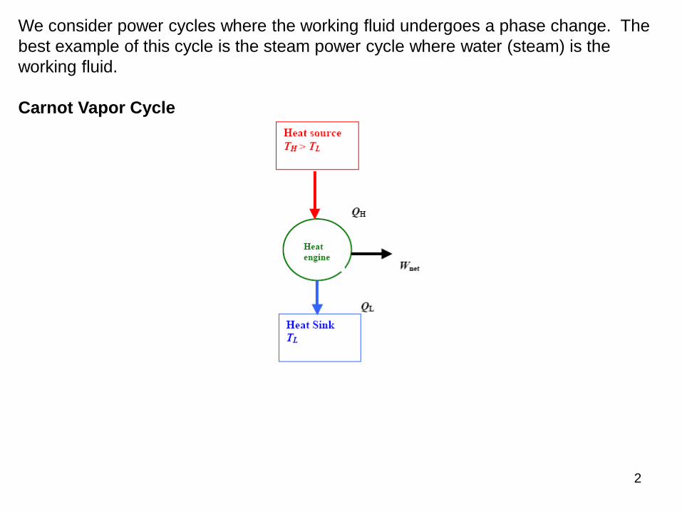
We consider power cycles where the working fluid undergoes a phase change. The
best example of this cycle is the steam power cycle where water (steam) is the
working fluid.
Carnot Vapor Cycle
3
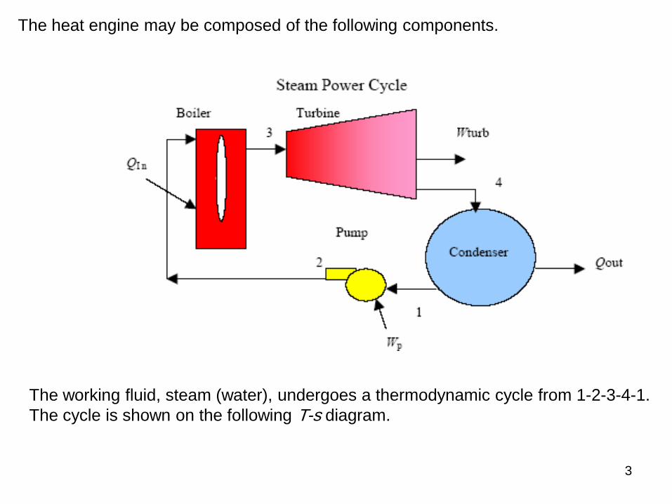
The heat engine may be composed of the following components.
The working fluid, steam (water), undergoes a thermodynamic cycle from 1-2-3-4-1.
The cycle is shown on the following T-s diagram.
4
0.0 1.0 2.0 3.0 4.0 5.0 6.0 7.0 8.0 9.0 10.0
0
100
200
300
400
500
600
700700
s [kJ/kg-K]
T [
C]
6000 kPa
100 kPa
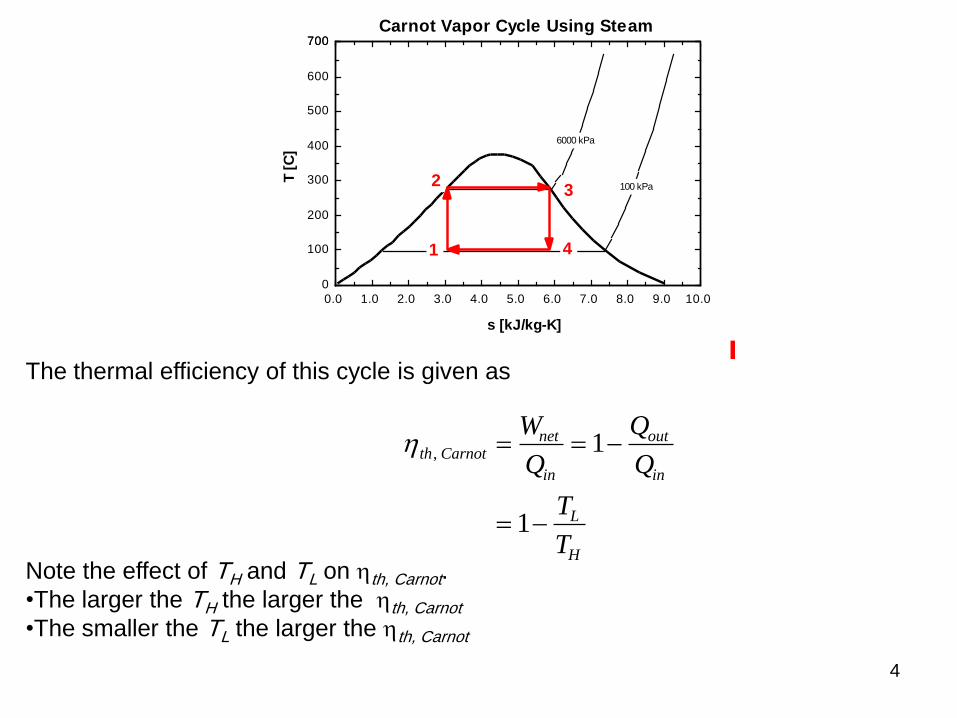
Carnot Vapor Cycle Using Steam
1
23
4
The thermal efficiency of this cycle is given as
th Carnotnet
in
out
in
L
H
W
Q
Q
Q
T
T
,
1
1
Note the effect of TH and TL on th, Carnot.
•The larger the TH the larger the th, Carnot
•The smaller the TL the larger the th, Carnot
5
To increase the thermal efficiency in any power cycle, we try to increase the
maximum temperature at which heat is added.
Reasons why the Carnot cycle is not used:
•Pumping process 1-2 requires the pumping of a mixture of saturated liquid and
saturated vapor at state 1 and the delivery of a saturated liquid at state 2.
•To superheat the steam to take advantage of a higher temperature, elaborate
controls are required to keep TH constant while the steam expands and does work.
To resolve the difficulties associated with the Carnot cycle, the Rankine cycle was
devised.
Rankine Cycle
The simple Rankine cycle has the same component layout as the Carnot cycle
shown above. The simple Rankine cycle continues the condensation process 4-1
until the saturated liquid line is reached.
Ideal Rankine Cycle Processes
Process Description
1-2 Isentropic compression in pump
2-3 Constant pressure heat addition in boiler
3-4 Isentropic expansion in turbine
4-1 Constant pressure heat rejection in condenser
6
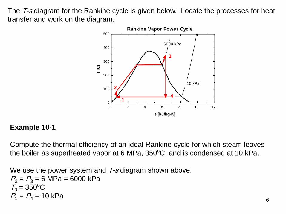
The T-s diagram for the Rankine cycle is given below. Locate the processes for heat
transfer and work on the diagram.
0 2 4 6 8 10 1212
0
100
200
300
400
500
s [kJ/kg-K]
T [
C]
6000 kPa
10 kPa
Rankine Vapor Power Cycle
1
2
3
4
Example 10-1
Compute the thermal efficiency of an ideal Rankine cycle for which steam leaves
the boiler as superheated vapor at 6 MPa, 350oC, and is condensed at 10 kPa.
We use the power system and T-s diagram shown above.
P2 = P3 = 6 MPa = 6000 kPa
T3 = 350oC
P1 = P4 = 10 kPa

7
Pump
The pump work is obtained from the conservation of mass and energy for steady-flow
but neglecting potential and kinetic energy changes and assuming the pump is
adiabatic and reversible.
( )
m m m
m h W m h
W m h h
pump
pump
1 2
1 1 2 2
2 1
Since the pumping process involves an incompressible liquid, state 2 is in the
compressed liquid region, we use a second method to find the pump work or the h
across the pump.
Recall the property relation:
dh = T ds + v dP
Since the ideal pumping process 1-2 is isentropic, ds = 0.

8
The incompressible liquid assumption allows
v v const
h h v P P
1
2 1 1 2 1
.
( )
The pump work is calculated from
( ) ( )
( )
W m h h mv P P
wW
mv P P
pump
pump
pump
2 1 1 2 1
1 2 1
Using the steam tables
1
1
3
1
191.8110
.0.00101
f
f
kJh h
kgP kPa
Sat liquid mv v
kg
w v P P
m
kgkPa
kJ
m kPa
kJ
kg
pump
1 2 1
3
30 00101 6000 10
6 05
( )
. ( )
.

9
Now, h2 is found from
2 1
6.05 191.81
197.86
pumph w h
kJ kJ
kg kg
kJ
kg
Boiler
To find the heat supplied in the boiler, we apply the steady-flow conservation of mass
and energy to the boiler. If we neglect the potential and kinetic energies, and note
that no work is done on the steam in the boiler, then
( )
m m m
m h Q m h
Q m h h
in
in
2 3
2 2 3 3
3 2
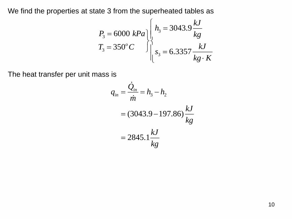
10
We find the properties at state 3 from the superheated tables as
3
3
33
3043.96000
3506.3357
o
kJh
P kPa kg
kJT Cs
kg K
The heat transfer per unit mass is
3 2
(3043.9 197.86)
2845.1
inin
Qq h h
m
kJ
kg
kJ
kg
11
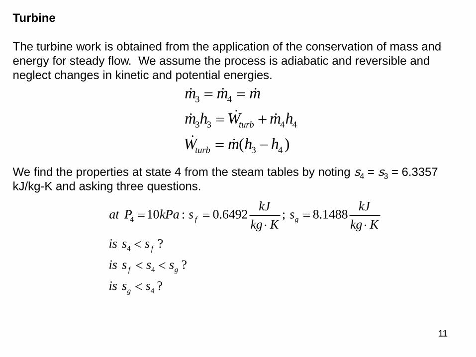
Turbine
The turbine work is obtained from the application of the conservation of mass and
energy for steady flow. We assume the process is adiabatic and reversible and
neglect changes in kinetic and potential energies.
( )
m m m
m h W m h
W m h h
turb
turb
3 4
3 3 4 4
3 4
We find the properties at state 4 from the steam tables by noting s4 = s3 = 6.3357
kJ/kg-K and asking three questions.
4
4
4
4
10 : 0.6492 ; 8.1488
?
?
?
f g
f
f g
g
kJ kJat P kPa s s
kg K kg K
is s s
is s s s
is s s
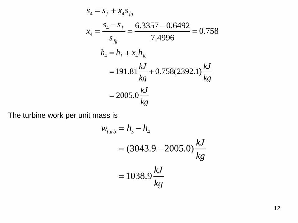
12
4 4
4
4
6.3357 0.64920.758
7.4996
f fg
f
fg
s s x s
s sx
s
4 4
191.81 0.758(2392.1)
2005.0
f fgh h x h
kJ kJ
kg kg
kJ
kg
The turbine work per unit mass is
3 4
(3043.9 2005.0)
1038.9
turbw h h
kJ
kg
kJ
kg
13
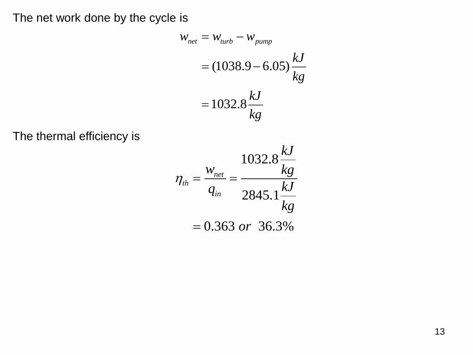
The net work done by the cycle is
(1038.9 6.05)
1032.8
net turb pumpw w w
kJ
kg
kJ
kg
The thermal efficiency is
1032.8
2845.1
0.363 36.3%
netth
in
kJ
w kg
kJq
kg
or

14
Ways to improve the simple Rankine cycle efficiency:
• Superheat the vapor
Average temperature is higher during heat addition.
Moisture is reduced at turbine exit (we want x4 in the above example > 85
percent).
• Increase boiler pressure (for fixed maximum temperature)
Availability of steam is higher at higher pressures.
Moisture is increased at turbine exit.
• Lower condenser pressure
Less energy is lost to surroundings.
Moisture is increased at turbine exit.
Extra Assignment
For the above example, find the heat rejected by the cycle and evaluate the thermal
efficiency from
thnet
in
out
in
w
q
q
q 1

15
Reheat Cycle
As the boiler pressure is increased in the simple Rankine cycle, not only does the
thermal efficiency increase, but also the turbine exit moisture increases. The reheat
cycle allows the use of higher boiler pressures and provides a means to keep the
turbine exit moisture (x > 0.85 to 0.90) at an acceptable level.
Let’s sketch the T-s diagram for the reheat cycle. T
s
t

16
Rankine Cycle with Reheat
Component Process First Law Result
Boiler Const. P qin = (h3 - h2) + (h5 - h4)
Turbine Isentropic wout = (h3 - h4) + (h5 - h6)
Condenser Const. P qout = (h6 - h1)
Pump Isentropic win = (h2 - h1) = v1(P2 - P1)
The thermal efficiency is given by
thnet
in
w
q
h h h h h h
h h h h
h h
h h h h
( - ) + ( - ) - ( - )
( - ) + ( - )
( - ) + ( - )
3 4 5 6 2 1
3 2 5 4
6 1
3 2 5 4
1
17
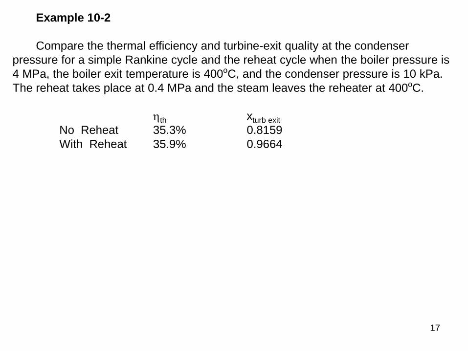
Example 10-2
Compare the thermal efficiency and turbine-exit quality at the condenser
pressure for a simple Rankine cycle and the reheat cycle when the boiler pressure is
4 MPa, the boiler exit temperature is 400oC, and the condenser pressure is 10 kPa.
The reheat takes place at 0.4 MPa and the steam leaves the reheater at 400oC.
th xturb exit
No Reheat 35.3% 0.8159
With Reheat 35.9% 0.9664

18
Regenerative Cycle
To improve the cycle thermal efficiency, the average temperature at which heat is
added must be increased.
One way to do this is to allow the steam leaving the boiler to expand the steam in the
turbine to an intermediate pressure. A portion of the steam is extracted from the
turbine and sent to a regenerative heater to preheat the condensate before entering
the boiler. This approach increases the average temperature at which heat is added
in the boiler. However, this reduces the mass of steam expanding in the lower-
pressure stages of the turbine, and, thus, the total work done by the turbine. The
work that is done is done more efficiently.
The preheating of the condensate is done in a combination of open and closed
heaters. In the open feedwater heater, the extracted steam and the condensate are
physically mixed. In the closed feedwater heater, the extracted steam and the
condensate are not mixed.
19
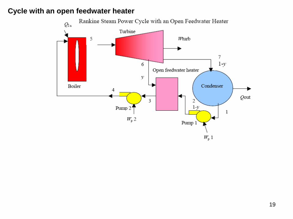
Cycle with an open feedwater heater

20
0 2 4 6 8 10 1212
0
100
200
300
400
500
600
s [kJ/kg-K]
T [
C]
3000 kPa
500 kPa
10 kPa
Rankine Steam Power Cycle with an Open Feedwater Heater
1
23
4
5
6
7
Cycle with a closed feedwater heater with steam trap to condenser

21
Let’s sketch the T-s diagram for this closed feedwater heater cycle.
T
s
22
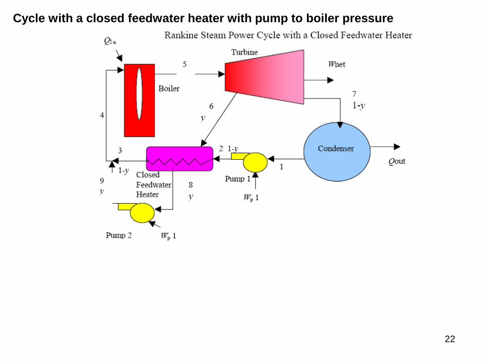
Cycle with a closed feedwater heater with pump to boiler pressure
23
Let’s sketch the T-s diagram for this closed feedwater heater cycle.
T
s
Consider the regenerative cycle with the open feedwater heater.
To find the fraction of mass to be extracted from the turbine, apply the first law to the
feedwater heater and assume, in the ideal case, that the water leaves the feedwater
heater as a saturated liquid. (In the case of the ideal closed feedwater heater, the
feedwater leaves the heater at a temperature equal to the saturation temperature at
the extraction pressure.)
Conservation of mass for the open feedwater heater:
24
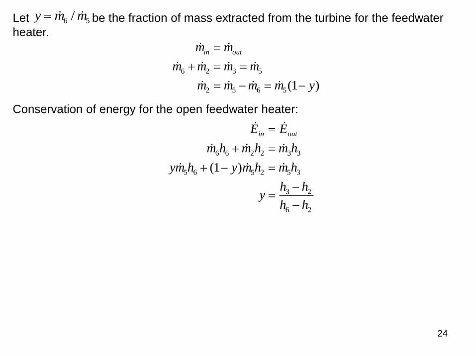
y m m / 6 5Let be the fraction of mass extracted from the turbine for the feedwater
heater.
( )
m m
m m m m
m m m m y
in out
6 2 3 5
2 5 6 5 1
Conservation of energy for the open feedwater heater:
( )
E E
m h m h m h
ym h y m h m h
yh h
h h
in out
6 6 2 2 3 3
5 6 5 2 5 3
3 2
6 2
1
25
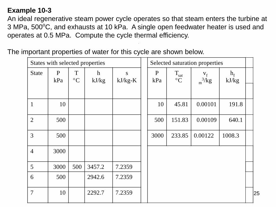
Example 10-3
An ideal regenerative steam power cycle operates so that steam enters the turbine at
3 MPa, 500oC, and exhausts at 10 kPa. A single open feedwater heater is used and
operates at 0.5 MPa. Compute the cycle thermal efficiency.
The important properties of water for this cycle are shown below.
States with selected properties Selected saturation properties
State P
kPa
T
C
h
kJ/kg
s
kJ/kg-K
P
kPa
Tsat
C
vf
m3/kg
hf
kJ/kg
1 10 10 45.81 0.00101 191.8
2 500 500 151.83 0.00109 640.1
3 500 3000 233.85 0.00122 1008.3
4 3000
5 3000 500 3457.2 7.2359
6 500 2942.6 7.2359
7 10 2292.7 7.2359
26
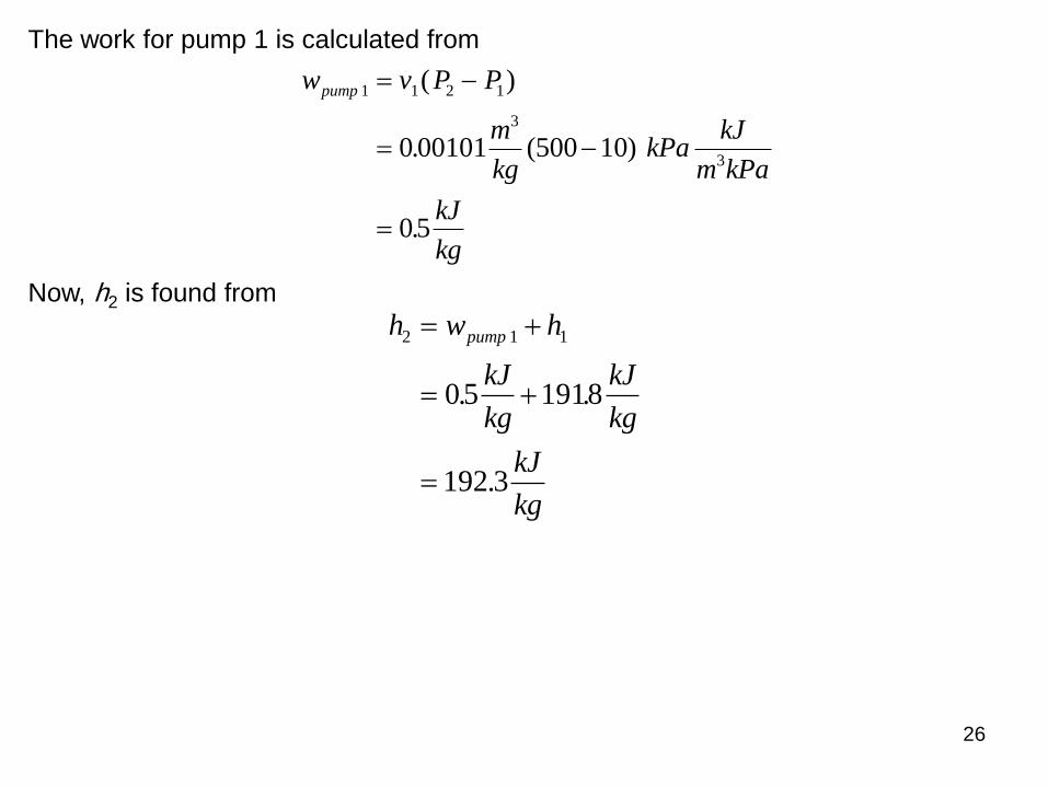
The work for pump 1 is calculated from
w v P P
m
kgkPa
kJ
m kPa
kJ
kg
pump 1 1 2 1
3
30 00101 10
05
( )
. (500 )
.
Now, h2 is found from
h w h
kJ
kg
kJ
kg
kJ
kg
pump2 1 1
05 1918
192 3
. .
.

27
The fraction of mass extracted from the turbine for the open feedwater heater is
obtained from the energy balance on the open feedwater heater, as shown above.
3 2
6 2
(640.1 192.3)
0.163
(2942.6 192.3)
kJ
h h kgy
kJh h
kg
This means that for each kg of steam entering the turbine, 0.163 kg is extracted for
the feedwater heater.
The work for pump 2 is calculated from
w v P P
m
kgkPa
kJ
m kPa
kJ
kg
pump 2 3 4 3
3
30 00109 3000 500
2 7
( )
. ( )
.
28
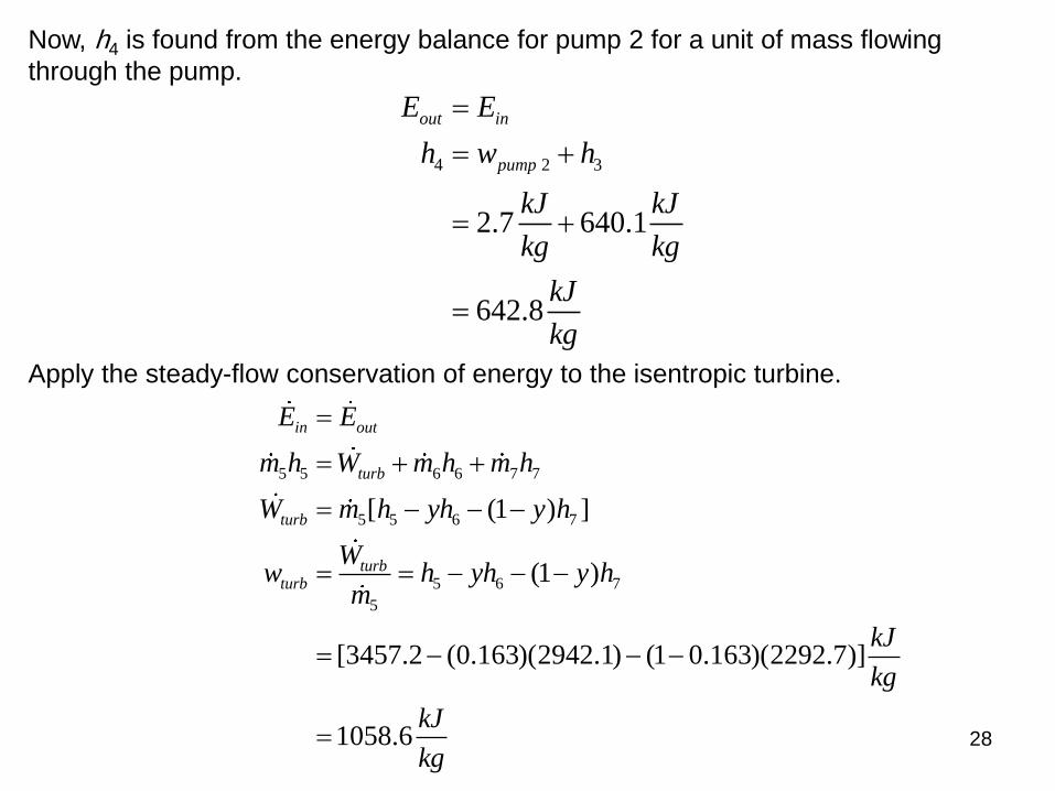
Now, h4 is found from the energy balance for pump 2 for a unit of mass flowing
through the pump.
4 2 3
2.7 640.1
642.8
out in
pump
E E
h w h
kJ kJ
kg kg
kJ
kg
Apply the steady-flow conservation of energy to the isentropic turbine.
5 5 6 6 7 7
5 5 6 7
5 6 7
5
[ (1 ) ]
(1 )
[3457.2 (0.163)(2942.1) (1 0.163)(2292.7)]
1058.6
in out
turb
turb
turbturb
E E
m h W m h m h
W m h yh y h
Ww h yh y h
m
kJ
kg
kJ
kg
29
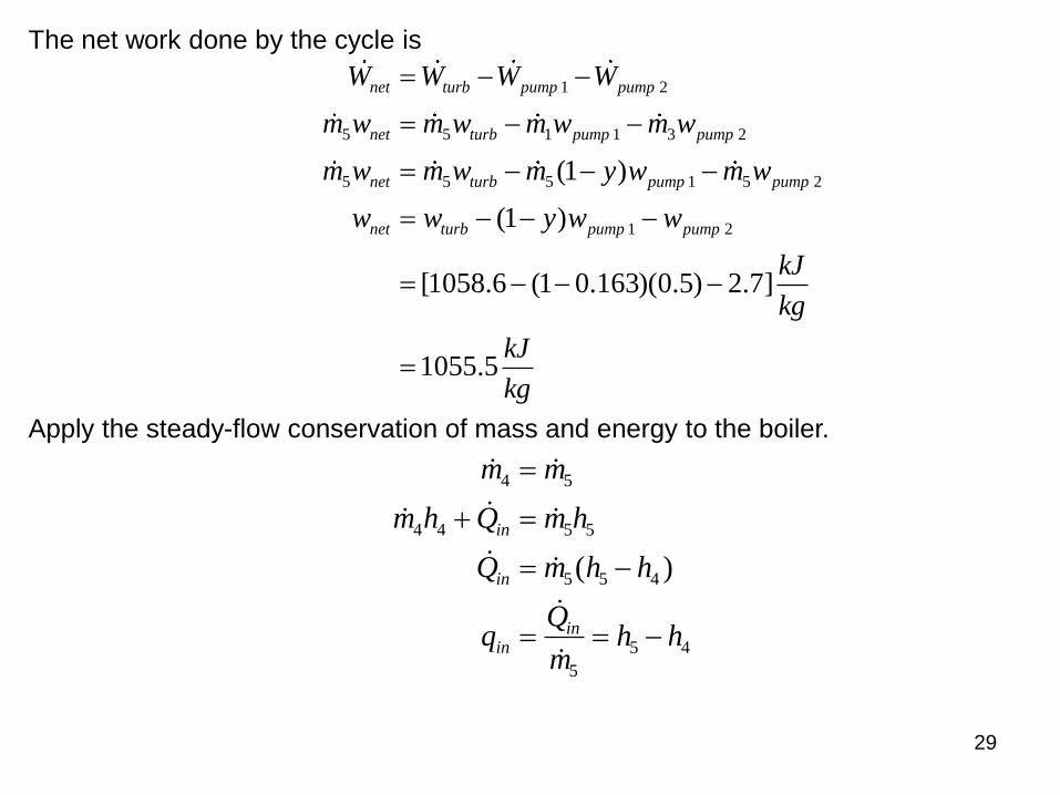
The net work done by the cycle is
1 2
5 5 1 1 3 2
5 5 5 1 5 2
1 2
(1 )
(1 )
[1058.6 (1 0.163)(0.5) 2.7]
1055.5
net turb pump pump
net turb pump pump
net turb pump pump
net turb pump pump
W W W W
m w m w m w m w
m w m w m y w m w
w w y w w
kJ
kg
kJ
kg
Apply the steady-flow conservation of mass and energy to the boiler.
( )
m m
m h Q m h
Q m h h
mh h
in
in
inin
4 5
4 4 5 5
5 5 4
5
5 4
30
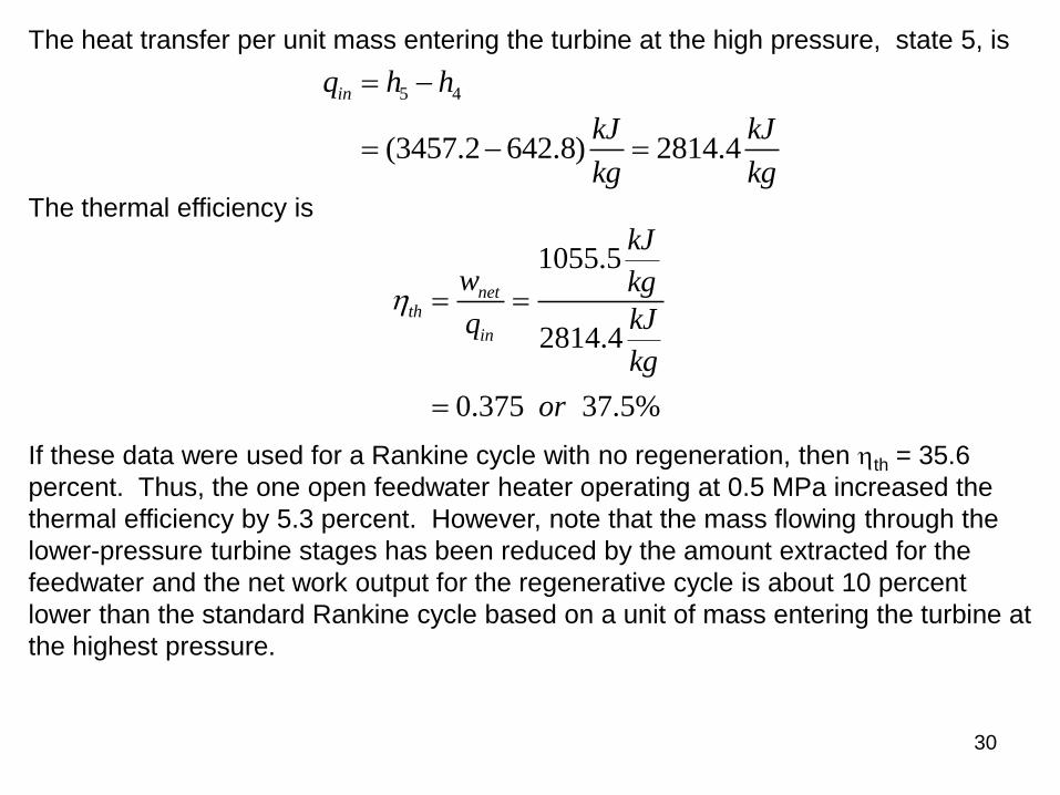
The heat transfer per unit mass entering the turbine at the high pressure, state 5, is
5 4
(3457.2 642.8) 2814.4
inq h h
kJ kJ
kg kg
The thermal efficiency is
1055.5
2814.4
0.375 37.5%
netth
in
kJ
w kg
kJq
kg
or
If these data were used for a Rankine cycle with no regeneration, then th = 35.6
percent. Thus, the one open feedwater heater operating at 0.5 MPa increased the
thermal efficiency by 5.3 percent. However, note that the mass flowing through the
lower-pressure turbine stages has been reduced by the amount extracted for the
feedwater and the net work output for the regenerative cycle is about 10 percent
lower than the standard Rankine cycle based on a unit of mass entering the turbine at
the highest pressure.
31
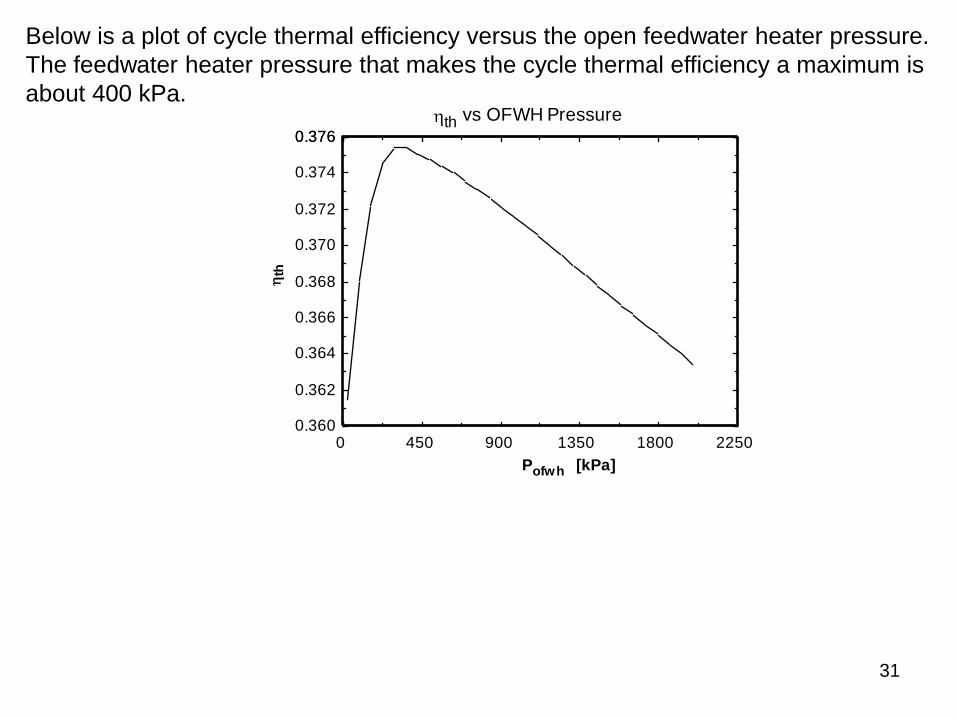
Below is a plot of cycle thermal efficiency versus the open feedwater heater pressure.
The feedwater heater pressure that makes the cycle thermal efficiency a maximum is
about 400 kPa.
0 450 900 1350 1800 22500.360
0.362
0.364
0.366
0.368
0.370
0.372
0.374
0.3760.376
Pofwh [kPa]
th
th vs OFWH Pressure

32
Below is a plot of cycle net work per unit mass flow at state 5 and the fraction of mass
y extracted for the feedwater heater versus the open feedwater heater pressure.
Clearly the net cycle work decreases and the fraction of mass extracted increases
with increasing extraction pressure. Why does the fraction of mass extracted
increase with increasing extraction pressure?
0 450 900 1350 1800 2250
900
950
1000
1050
1100
1150
1200
0.03
0.05
0.08
0.10
0.13
0.15
0.18
0.20
0.23
0.25
Pofwh [kPa]
wn
et k
J/k
g
y
wnet and y vs OFWH Pressure
33
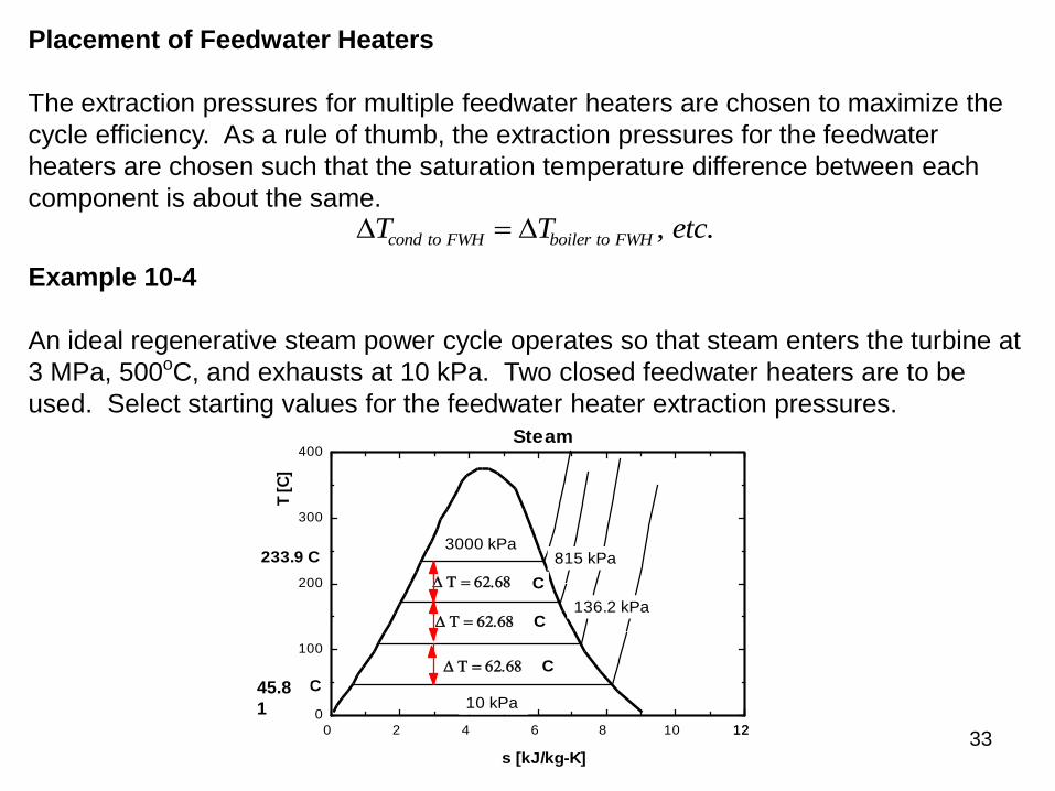
Placement of Feedwater Heaters
The extraction pressures for multiple feedwater heaters are chosen to maximize the
cycle efficiency. As a rule of thumb, the extraction pressures for the feedwater
heaters are chosen such that the saturation temperature difference between each
component is about the same. T T etccond to FWH boiler to FWH , .
Example 10-4
An ideal regenerative steam power cycle operates so that steam enters the turbine at
3 MPa, 500oC, and exhausts at 10 kPa. Two closed feedwater heaters are to be
used. Select starting values for the feedwater heater extraction pressures.
0 2 4 6 8 10 1212
0
100
200
300
400
s [kJ/kg-K]
T [
C]
3000 kPa 815 kPa
136.2 kPa
10 kPa
Steam
T 62.68
T 62.68
T 62.68
C
C
C
233.9 C
45.85 C
45.8
1
34
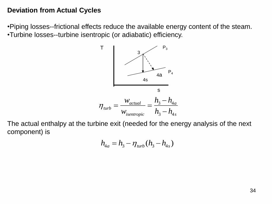
Deviation from Actual Cycles
•Piping losses--frictional effects reduce the available energy content of the steam.
•Turbine losses--turbine isentropic (or adiabatic) efficiency.
4a 4s
3
s
T P3
P4
turbactual
isentropic
a
s
w
w
h h
h h
3 4
3 4
The actual enthalpy at the turbine exit (needed for the energy analysis of the next
component) is
h h h ha turb s4 3 3 4 ( )
35
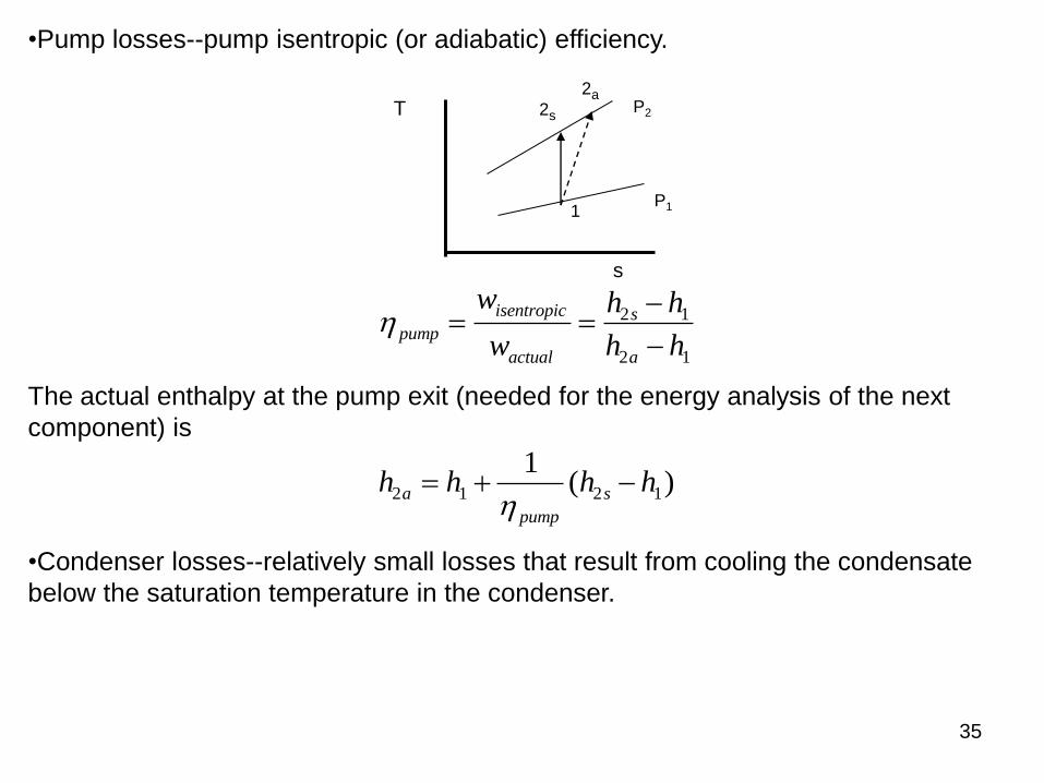
•Pump losses--pump isentropic (or adiabatic) efficiency.
2a 2s
1
s
T P2
P1
pump
isentropic
actual
s
a
w
w
h h
h h
2 1
2 1
The actual enthalpy at the pump exit (needed for the energy analysis of the next
component) is
h h h ha
pump
s2 1 2 1
1
( )
•Condenser losses--relatively small losses that result from cooling the condensate
below the saturation temperature in the condenser.

36
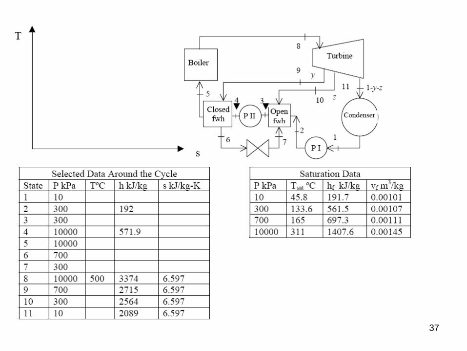
The following examples you should try on your own.
Regenerative Feedwater Heater problem
Consider an ideal steam regenerative Rankine cycle with two feedwater heaters, one
closed and one open. Steam enters the turbine at 10 MPa and 500 C and
exhausts to the condenser at 10 kPa. Steam is extracted from the turbine at 0.7
MPa for the closed feedwater heater and 0.3 MPa for the open one. The extracted
steam leaves the closed feedwater heater and is subsequently throttled to the
open feedwater heater. Show the cycle on a T-s diagram with respect to
saturation lines, and using only the data presented in the data tables given below
determine
a) the fraction of steam leaving the boiler that is extracted at 0.3 MPa z=0.1425
b) the fraction of steam leaving the boiler that is extracted at 0.7 MPa y=0.06213
c) the heat transfer from the condenser per unit mass leaving the boiler q_out=1509
kJ/kg
d) the heat transfer to the boiler per unit mass leaving the boiler q_in=2677 kJ/kg
e) the mass flow rate of steam through the boiler for a net power output of 250 MW
m_dot=214.1 kg/s
f) the thermal efficiency of the cycle. Eta_th=0.4363
37
38
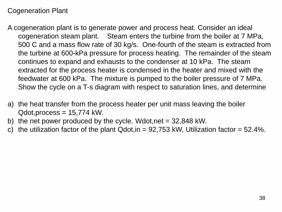
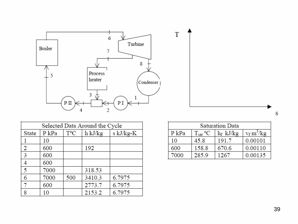
Cogeneration Plant
A cogeneration plant is to generate power and process heat. Consider an ideal
cogeneration steam plant. Steam enters the turbine from the boiler at 7 MPa,
500 C and a mass flow rate of 30 kg/s. One-fourth of the steam is extracted from
the turbine at 600-kPa pressure for process heating. The remainder of the steam
continues to expand and exhausts to the condenser at 10 kPa. The steam
extracted for the process heater is condensed in the heater and mixed with the
feedwater at 600 kPa. The mixture is pumped to the boiler pressure of 7 MPa.
Show the cycle on a T-s diagram with respect to saturation lines, and determine
a) the heat transfer from the process heater per unit mass leaving the boiler
Qdot,process = 15,774 kW.
b) the net power produced by the cycle. Wdot,net = 32,848 kW.
c) the utilization factor of the plant Qdot,in = 92,753 kW, Utilization factor = 52.4%.
39
40
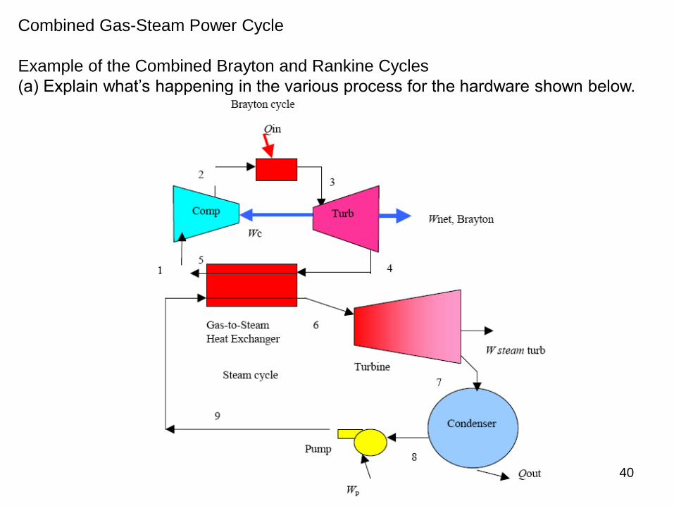
Combined Gas-Steam Power Cycle
Example of the Combined Brayton and Rankine Cycles
(a) Explain what’s happening in the various process for the hardware shown below.