vapor and combined power cycles - website staff ui
TRANSCRIPT

WCB/McGraw-Hill © The McGraw-Hill Companies, Inc.,1998
Thermo
Thermo dynam
icsdynam
ics
ÇÇengelengelBolesBoles
Third EditionThird Edition
9CHAPTERCHAPTER
Vapor andCombined
Power Cycles

WCB/McGraw-Hill © The McGraw-Hill Companies, Inc.,1998
Thermo
Thermo dynam
icsdynam
ics
ÇÇengelengelBolesBoles
Third EditionThird Edition
The Simple Ideal Rankine CycleThe Simple Ideal Rankine Cycle9-1
© The McGraw-Hill Companies, Inc.,1998

WCB/McGraw-Hill © The McGraw-Hill Companies, Inc.,1998
Thermo
Thermo dynam
icsdynam
ics
ÇÇengelengelBolesBoles
Third EditionThird Edition
Rankine Cycle: Actual Vapor Power Deviation and Pump and Turbine IrreversibilitiesRankine Cycle: Actual Vapor Power Deviation and Pump and Turbine Irreversibilities
9-2
(Fig. 9-4)
(a) Deviation of actual vapor power cycle from the ideal Rankine cycle.(b) The effect of pump and turbine irreversibilities on the ideal Rankine cycle.

WCB/McGraw-Hill © The McGraw-Hill Companies, Inc.,1998
Thermo
Thermo dynam
icsdynam
ics
ÇÇengelengelBolesBoles
Third EditionThird Edition
Effect of Lowering Condenser Pressure on the Ideal Rankine cycleEffect of Lowering Condenser Pressure on the Ideal Rankine cycle
(Fig. 9-6)
9-3

WCB/McGraw-Hill © The McGraw-Hill Companies, Inc.,1998
Thermo
Thermo dynam
icsdynam
ics
ÇÇengelengelBolesBoles
Third EditionThird Edition
Effect of Increasing Boiler Pressure on the Ideal Rankine cycleEffect of Increasing Boiler Pressure on the Ideal Rankine cycle
(Fig. 9-8)
9-4

WCB/McGraw-Hill © The McGraw-Hill Companies, Inc.,1998
Thermo
Thermo dynam
icsdynam
ics
ÇÇengelengelBolesBoles
Third EditionThird Edition
The Ideal Reheat Rankine CycleThe Ideal Reheat Rankine Cycle9-5
(Fig. 9-11)

WCB/McGraw-Hill © The McGraw-Hill Companies, Inc.,1998
Thermo
Thermo dynam
icsdynam
ics
ÇÇengelengelBolesBoles
Third EditionThird Edition
Ideal Regenerative Rankine Cycle with Open Feedwater HeaterIdeal Regenerative Rankine Cycle with Open Feedwater Heater
9-6
(Fig. 9-15)

WCB/McGraw-Hill © The McGraw-Hill Companies, Inc.,1998
Thermo
Thermo dynam
icsdynam
ics
ÇÇengelengelBolesBoles
Third EditionThird Edition
Ideal Regenerative Rankine Cycle with Closed Feedwater HeaterIdeal Regenerative Rankine Cycle with Closed Feedwater Heater
9-7
(Fig. 9-16)
WCB/McGraw-Hill © The McGraw-Hill Companies, Inc.,1998
Thermo
Thermo dynam
icsdynam
ics
ÇÇengelengelBolesBoles
Third EditionThird Edition
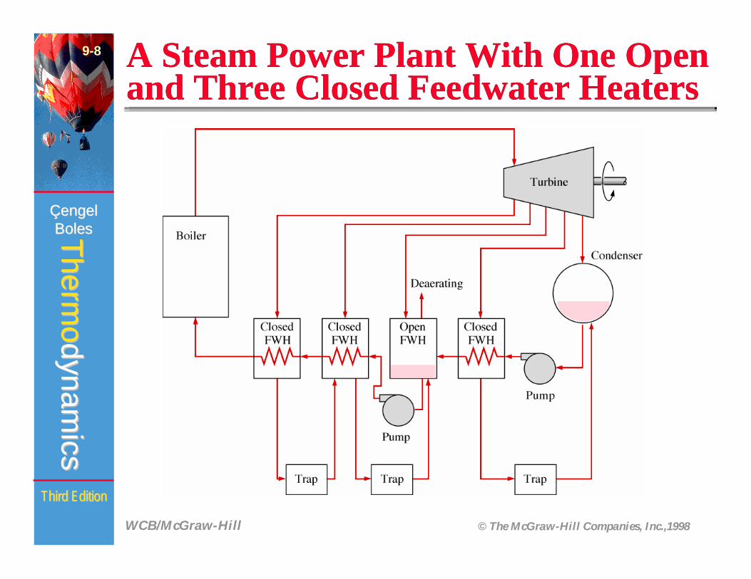
A Steam Power Plant With One Open and Three Closed Feedwater HeatersA Steam Power Plant With One Open and Three Closed Feedwater Heaters
9-8
(Fig. 9-17)

WCB/McGraw-Hill © The McGraw-Hill Companies, Inc.,1998
Thermo
Thermo dynam
icsdynam
ics
ÇÇengelengelBolesBoles
Third EditionThird Edition
An Ideal Cogeneration PlantAn Ideal Cogeneration Plant9-9
(Fig. 9-21)

WCB/McGraw-Hill © The McGraw-Hill Companies, Inc.,1998
Thermo
Thermo dynam
icsdynam
ics
ÇÇengelengelBolesBoles
Third EditionThird Edition
Schematic and T-s Diagram for Example 9-8Schematic and T-s Diagram for Example 9-8
9-10
(Fig. 9-23)

WCB/McGraw-Hill © The McGraw-Hill Companies, Inc.,1998
Thermo
Thermo dynam
icsdynam
ics
ÇÇengelengelBolesBoles
Third EditionThird Edition
Mercury-Water Binary Vapor CycleMercury-Water Binary Vapor Cycle
9-11
(Fig. 9-24)

WCB/McGraw-Hill © The McGraw-Hill Companies, Inc.,1998
Thermo
Thermo dynam
icsdynam
ics
ÇÇengelengelBolesBoles
Third EditionThird Edition
Combined Gas-Steam Power PlantCombined Gas-Steam Power Plant9-12

WCB/McGraw-Hill © The McGraw-Hill Companies, Inc.,1998
Thermo
Thermo dynam
icsdynam
ics
ÇÇengelengelBolesBoles
Third EditionThird Edition
Chapter SummaryChapter Summary• The Carnot cycle is not a suitable model for vapor
power cycles because it cannot be approximated in practice.
• The model cycle for vapor power cycles is the Rankine cycle which is composed of four internally reversible processes: constant-pressure heat addition in a boiler, isentropic expansion in a turbine, constant-pressure heat rejection in a condenser, and isentropic compression in a pump. Steam leaves the condenser as a saturated liquid at the condenser pressure.
9-13

WCB/McGraw-Hill © The McGraw-Hill Companies, Inc.,1998
Thermo
Thermo dynam
icsdynam
ics
ÇÇengelengelBolesBoles
Third EditionThird Edition
Chapter SummaryChapter Summary
• The thermal efficiency of the Rankine cycle can be increased by increasing the average temperature at which heat is added to the working fluid and/or by decreasing the average temperature at which heat is rejected to the cooling medium. The average temperature during heat rejection can be decreased by lowering the turbine exit pressure. Consequently, the condenser pressure of most vapor power plants is well below the atmospheric pressure. The average temperature during heat addition can be increased by raising the boiler pressure or by superheating the fluid to high temperatures. There is a limit to the degree of superheating, however, since the fluid temperature is not allowed to exceed ametallurgically safe value.
9-15

WCB/McGraw-Hill © The McGraw-Hill Companies, Inc.,1998
Thermo
Thermo dynam
icsdynam
ics
ÇÇengelengelBolesBoles
Third EditionThird Edition
Chapter SummaryChapter Summary• Superheating has the added advantage of decreasing
the moisture content of the steam at the turbine exit. Lowering the exhaust pressure or raising the boiler pressure, however, increases the moisture content. To take advantage of the improved efficiencies at higher boiler pressures and lower condenser pressures, steam is usually reheated after expanding partially in the high-pressure turbine. This is done by extracting the steam after partial extraction in the high-pressure turbine, sending it back to the boiler where it is reheated at constant pressure, and returning it to the low-pressure turbine for complete expansion to the condenser pressure. The average temperature during the reheat process, and thus the thermal efficiency of the cycle, can be increased by increasing the number of expansion and reheat stages. As the number of stages is increased, the expansion and reheat processes approach an isother-mal process at maximum temperature. Reheating also decreases the moisture content at the turbine exit.
9-16
WCB/McGraw-Hill © The McGraw-Hill Companies, Inc.,1998
Thermo
Thermo dynam
icsdynam
ics
ÇÇengelengelBolesBoles
Third EditionThird Edition
Chapter SummaryChapter Summary
• Another way of increasing the thermal efficiency of the Rankine cycle is by regeneration. During a regeneration process, liquid water (feedwater) leaving the pump is heated by some steam bled off the turbine at some intermediate pressure in devices called feedwater heaters. The two streams are mixed in open feedwater heaters, and the mixture leaves as a saturated liquid at the heater pressure. In closed feedwater heaters, heat is transferred from the steam to the feedwaterwithout mixing.
9-17

WCB/McGraw-Hill © The McGraw-Hill Companies, Inc.,1998
Thermo
Thermo dynam
icsdynam
ics
ÇÇengelengelBolesBoles
Third EditionThird Edition
Chapter SummaryChapter Summary
• The production of more than one useful form of energy (such as process heat and electric power) from the same energy source is calledcogeneration. Cogeneration plants produce electric power while meeting the process heat requirements of certain industrial processes. This way, more of the energy transferred to the fluid in the boiler is utilized for a useful purpose. The faction of energy that is used for either process heat or power generation is called the utilization factor of the cogeneration plant.
9-18

WCB/McGraw-Hill © The McGraw-Hill Companies, Inc.,1998
Thermo
Thermo dynam
icsdynam
ics
ÇÇengelengelBolesBoles
Third EditionThird Edition
Chapter SummaryChapter Summary
• The overall thermal efficiency of a power plant can be increased by using binary cycles or combined cycles. A binary cycle is composed of two separate cycles, one at high temperatures (topping cycle) and the other at relatively low temperatures. The most common combined cycle is the gas-steam combined cycle where a gas-turbine cycle operates at the high-temperature range and a steam-turbine cycle at the low-temperature range. Steam is heated by the high-temperature exhaust gases leaving the gas turbine. Combined cycles have a higher thermal efficiency than the steam- or gas-turbine cycles operating alone.
9-19