chapter 14 capacitors in ac and dc circuits - sign infaculty.polytechnic.org/cfletcher/honorstext...
TRANSCRIPT

Chapter 14--Capacitors
521
FIGURE 14.1b
standard symbol for a capacitor
+ -
alternate symbol-- a DC capacitor
FIGURE 14.1a
Chapter 14
CAPACITORS IN AC AND DC CIRCUITS
So far, all we have discussed have been electrical elements in which thevoltage across the element is proportional to the current through the element (i.e.,elements like the resistor that obey Ohm's Law). There are electrical elementsthat do not follow this pattern. One of these elements is the capacitor--a critterthat has very different characteristics when found in an AC circuit as opposed to aDC circuit. This chapter is devoted to that lowly creature.
A.) Capacitors in General:
1.) The circuit symbol for the capacitor(see Figures 14.1a and 14.1b) evokes a feeling forwhat a capacitor really is. Physically, it is nomore than two plates (the symbol depicts theside view) that do not touch (there is normallyinsulation placed between the two plates toinsure no contact). In other words, a capacitor ina circuit technically effects a break in the circuit.
Note: Although there are AC capacitorsmade to take high voltage at either terminal, DC capacitors have definite highand low voltage sides. When a designer of circuitry wants to specify a DCcapacitor, he or she uses the symbol shown in Figure 14.1b. The straight side ofthat symbol is designated the high voltage side (the positive terminal) while thecurved side is designated the low voltage side. We will use either symbol in DCsituations.
2.) A circuit element that does not allow charge to freely flow through itprobably sounds like a fairly useless device. In fact, capacitors do allow current toflow in the circuit under the right conditions.
3.) Consider a circuit in which there is an initially uncharged capacitor, aDC power supply, a resistor, and an initially open switch (this is commonly calledan RC circuit).
a.) When the switch is first closed, neither plate has charge on it. Thismeans there is no voltage difference between the two. As the right-hand

522
electrical potential configurationfor RC circuit at time t = 0 (plus a hair)
FIGURE 14.2a
switch(closes at t = 0)
V=0
left plate
right plate
oV=V
oV=V
V=0
V=0 V=0
plate is connected to the groundterminal of the battery, both platesmust have an initial electricalpotential of zero (see Figure 14.2a).
b.) Just after the switch isclosed, a voltage difference existsacross the resistor (again, see Figure14.2a) and, hence, current flowsthrough the circuit. (Remember, thevoltage across a resistor isproportional to the current throughit--if the voltage is relatively large,the current will be relatively large, ifthe voltage is relatively small, the current will be relatively small.)
c.) As time proceeds, positive charge accumulates on the capacitor's leftplate (this is looking at the circuit from a conventional current perspectivein which positive charge moves).
d.) As it does, two things happen:
i.) Electrostatic repulsion from the positive charge accumulated onthe left plate forces an equal amount of positive charge off the rightplate. That leaves the right plate electrically negative.
Note: The amount of negative charge on the right plate is always equal tothe amount of positive charge on the left plate. That means that current appearsto be passing through a capacitor even though the capacitor's plates are notconnected.
ii.) The second consequence is that the left plate's voltage begins toincrease and a voltage difference begins to form across the capacitor'splates.
e.) As the voltage of the capacitor's left plate increases, the voltage onthe resistor's low voltage side also begins to increase (that point and thecapacitor's left plate are the same point). This decreases the voltagedifference across the resistor.
f.) Figure 14.2b (next page) shows the voltage distribution around thecircuit midway through the capacitor's charge-up cycle. This, in turn,decreases the current in the circuit.

Chapter 14--Capacitors
523
electrical potential configuration for RC circuit at some arbitrary time after switch closed
FIGURE 14.2b
switch closed for a time
V=0
oV=V
V=0
oV=V
V=V1
V=V1
voltage difference acrosscapacitor plates increasing
voltage drop acrossresistor decreasing
g.) Figure 14.3(below) shows theCurrent vs. Time graphfor a circuit in which acapacitor is charging.
h.) In looking backat Figure 14.2b, it shouldbe obvious that currentwill flow until thevoltage of the capacitor'sleft plate equals thevoltage of the powersupply's high voltageterminal and the voltage
current
time
FIGURE 14.3
difference across the resistor is zero. Putanother way, once the voltage across thecapacitor equals the voltage across the powersupply, current ceases.
Note 1: In a little different light, current willflow until the left plate holds as much charge as itcan, given the size of the power source to which it isattached.
voltage distribution a long time after switch is closed
FIGURE 14.4
switch closed for a time
V=0
V=0
oV=V
oV=V
V=0
V=0
Note 2: Does this analysishold in theory if we switch thepositions of the capacitor andresistor? Figure 14.4 shows thesituation along with the circuit'svoltage distribution after the switchhas been closed for a long time.Notice that the voltage drop acrossthe capacitor is still equal to thevoltage across the power supplywhen the current in the circuit alongwith the voltage across the resistorgoes to zero.
524
FIGURE 14.5
+Q
E field
-Q
-
+
a charged capacitor stores energy in the form of anelectric field between its plates
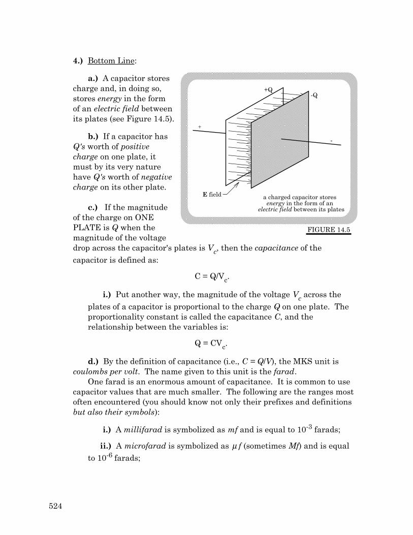
4.) Bottom Line:
a.) A capacitor storescharge and, in doing so,stores energy in the formof an electric field betweenits plates (see Figure 14.5).
b.) If a capacitor hasQ's worth of positivecharge on one plate, itmust by its very naturehave Q's worth of negativecharge on its other plate.
c.) If the magnitudeof the charge on ONEPLATE is Q when themagnitude of the voltagedrop across the capacitor's plates is Vc, then the capacitance of thecapacitor is defined as:
C = Q/Vc.
i.) Put another way, the magnitude of the voltage Vc across theplates of a capacitor is proportional to the charge Q on one plate. Theproportionality constant is called the capacitance C, and therelationship between the variables is:
Q = CVc.
d.) By the definition of capacitance (i.e., C = Q/V), the MKS unit iscoulombs per volt. The name given to this unit is the farad.
One farad is an enormous amount of capacitance. It is common to usecapacitor values that are much smaller. The following are the ranges mostoften encountered (you should know not only their prefixes and definitionsbut also their symbols):
i.) A millifarad is symbolized as mf and is equal to 10-3 farads;
ii.) A microfarad is symbolized as µ f (sometimes Mf) and is equalto 10-6 farads;

Chapter 14--Capacitors
525
+ -
C
switch
Vo
R
FIGURE 14.6
+ -
Vo
C2C1 C3
capacitors in series have common charge per plate
switchclosesat t=0
FIGURE 14.7
iii.) A nanofarad is symbolized as nf and is equal to 10-9 farads;
iv.) A picofarad is symbolized as pf and is equal to 10-12 farads.
5.) Example of a Capacitor In Action: Con-sider the camera-flash circuit shown in Figure 14.6.
a.) The switch is initially connected in thedown position so that the capacitor is hookedacross the power supply. This allows thecapacitor's plates to charge up.
b.) When the flash is activated, the switchflips to the up position. The capacitordischarges across the resistor (i.e., chargeflows from one plate to the other, passingthrough the resistor/lightbulb in the process)with the large, momentary charge-flowlighting the flashbulb.
c.) Once fired, the switch automatically flips down allowing thecapacitor to once again charge itself off the power supply.
B.) Equivalent Capacitance of Parallel and Series Combinations:
1.) The Equivalent Capacitance for Capacitors in Series:
a.) Just as current is common forall resistors connected in series,charge accumulation on capacitorplates is the common quantity forcapacitors in series.
i.) Examining Figure 14.7,the positive charge electricallyforced off the right plate of thefirst capacitor must go some-where. Where? It accumulateson the left plate of the secondcapacitor.
526
+ -
C
switchclosesat t = 0
Vo
FIGURE 14.8
C
C
1
2
3
ii.) Conclusion: The amount of charge associated with each seriescapacitor must be the same.
b.) At a given instant, the sum of the voltage drops across the threecapacitors must equal the voltage drop across the power supply, or:
Vo = V1 + V2 + V3 + . . .
c.) As the voltage across a capacitor is related to the charge on andcapacitance of a capacitor (V = Q/C), we can write:
Vo = V1 + V2 + V3 + . . . Q/Ceq = Q/C1 + Q/C2 + Q/C3 + . . .
d.) With the Q's canceling nicely, we end up with:
1/Ceq = 1/C1 + 1/C2 + 1/C3.
e.) In other words, the equivalent capacitance for a series combinationof capacitors has the same mathematical form as that of a parallelcombination for resistors.
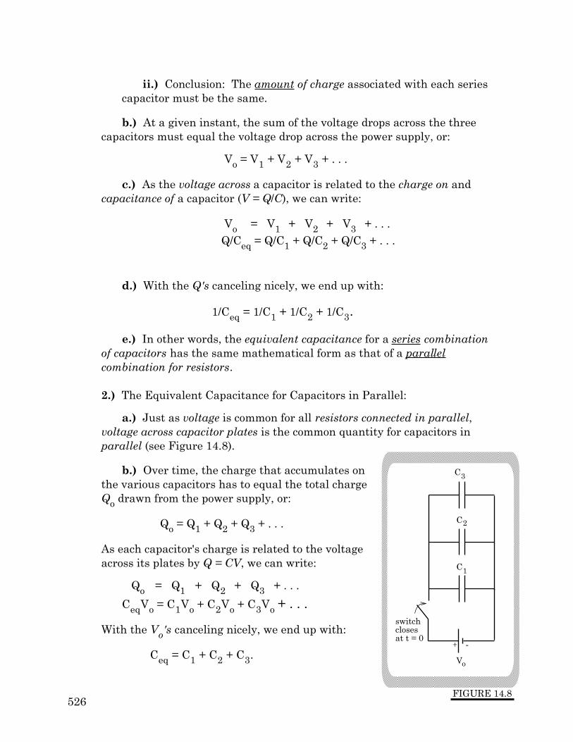
2.) The Equivalent Capacitance for Capacitors in Parallel:
a.) Just as voltage is common for all resistors connected in parallel,voltage across capacitor plates is the common quantity for capacitors inparallel (see Figure 14.8).
b.) Over time, the charge that accumulates onthe various capacitors has to equal the total chargeQo drawn from the power supply, or:
Qo = Q1 + Q2 + Q3 + . . .
As each capacitor's charge is related to the voltageacross its plates by Q = CV, we can write:
Qo = Q1 + Q2 + Q3 + . . .
CeqVo = C1Vo + C2Vo + C3Vo + . . .
With the Vo's canceling nicely, we end up with:
Ceq = C1 + C2 + C3.

Chapter 14--Capacitors
527
DC version of an RC circuit
FIGURE 14.9
switch closesat t = 0 seconds
R
C
Vo
c.) In other words, the equivalent capacitance for a parallelcombination of capacitors has the same mathematical form as that of theseries combination for resistors.
C.) The Current Characteristics of a Charging Capacitor in a DC Circuit:
1.) Because there is no charge on the plates of an uncharged capacitor, acapacitor will initially provide no resistance to charge flow in an RC circuit.
a.) This means all of the initial voltage drop in the circuit is across theresistor, which means the initial current io in the circuit is
Vo = ioR,or
io = Vo/R.
2.) As the capacitor charges up, it will become increasingly more difficultfor additional charge to be forced onto the capacitor's plates. As such, the currentin the circuit will decrease.
a.) We would like to derive an expression for the current in a DC-RCcircuit as a function of time, but we really don't need the derivation to getat the good stuff. All we need now are the basics.
b.) Figure 14.9 shows the circuit.Remembering that the voltage dropacross a capacitor will be q/C, we canuse Kirchoff's Laws to write:
Vo - (qplate/C) - iR = 0,
where qplate is the charge on thecapacitor and i is the conventionalcurrent in the circuit.
c.) Noticing that the rate atwhich charge flows onto the capacitorplates (i.e., dqplate/dt) is, in this case,equal to the charge flow in the circuit(i.e., the current i, or dqflow/dt), we can divide through by R and re-rewritethis as:

528
current in circuit (amps)
time (sec)
i =V /Ro o
.37 io
one time constant (time required for current to drop 63%; numerically equal to RC)
FIGURE 14.10
i(t) = i eo-t/RC
dq flow
dt+
1
RC
qplate =
V o
R,
or
dqplate
dt+
1
RC
qplate =
V o
R.
Minor Note: If the capacitor had been discharging, dqplate/dt would beNEGATIVE and the qflow/qplate relationship would be i = dqflow/dt = -dqplate/dt. Ifthis bit of whimsy is missed, you will end up with mush for a solution.
d.) This differential equation essentially states that we are looking fora function qplate such that when we take its derivative (i.e., dqplate/dt) andadd to it a constant times itself (i.e., (1/RC)qplate), we will always get thesame number (in this case, Vo/R).
e.) Bottom line #1: Solving our differential equation yields a solutionthat defines how much charge there will be on the capacitor as afunction of time. That function is
q flow (t) = Qmax (1− e− t
RC ),
where Qmax = CVo.
f.) Bottom line #2: Thefunction that defines thecurrent in the circuit as afunction of time is thederivative of our qflowfunction, or
i(t) = ioe− t
RC,
where the initial current ioin the circuit is io = Vo/R.
g.) See Figure 14.10.

Chapter 14--Capacitors
529
3.) The graph of the current as a function of time for a charging capacitorvisually points out several important things.
a.) Initially, the current through an RC circuit in which the capacitoris initially uncharged is at a maximum. That is, the capacitor initially actslike it is a short (i.e., not even there). It isn't until charge begins toaccumulate that charge flow begins to diminish.
b.) The graph identifies a particular point in time that has beendeemed important. It is the amount of time associated with what is calledone time constant.
i.) One time constant is defined as τ = RC, where the symbol τ is alower case tau.
ii.) Putting one time constant into our current expression (i.e., lettingt = RC) yields:
i = ioe-RC/RC
= io(e-1)= .37io.
iii.) Bottom line: One time constant is the amount of time it takesthe circuit's current to diminish to 37% of its initial value.
iv.) It is also the amount of time it takes for the capacitor to chargeup to 63% of its initial charge (to see this, put one time constant in thecharge expression).
c.) What does this tell us? It tells us that if we multiply the value ofthe capacitance and resistance together (i.e., RC ), the number we end upwith will:
i.) Have the units of seconds (this has to be the case if the exponentis to be unitless);
ii.) Be the amount of time required for the capacitor to charge to63% of its maximum; and
iii.) Be the amount of time required for the current to drop to 37% ofits maximum.

530
capacitor plates as viewed from the side
+Q -Q
+ -
DIELECTRIC
FIGURE 14.11
Note 1: In doing the math, the time interval 2t will give us approximately87% charge-up for the capacitor and a current that will have dropped toapproximately 13% of its initial value.
Note 2: The charge/discharge characteristics of a capacitor in an RC circuitare symmetric. That is, the time it takes to charge a capacitor to 63% of itsmaximum is the same amount of time required for the charged capacitor todischarge 63% of its charge (leaving 37% on the cap).
d.) Why is t important? It would be idiotic to build a camera flashusing a resistor and capacitor whose time constant was, say, ten seconds.Waiting twenty seconds for 87% of your charge to dump through theresistor would never do. A system's time constant is a very useful quantityto know.
D.) Dielectrics:
1.) Consider the situation in which apiece of insulating material, called adielectric, is placed between the plates of thecapacitor (see Figure 14.11). The capacitoris charged, then isolated (that is, oncecharged it is disconnected from the powersupply). What must be true?
a.) Let Eo be the electric fieldwithout the dielectric between thecapacitor's plates.
b.) When the insulator is placedbetween the plates, the surface of theinsulator facing the positive plate ofthe capacitor will experience a Vander Waal-type charge separation thatmakes that face appear negative. A similar effect will be found on the otherface making it appear positive.
Chapter 14--Capacitors
531
charge induced on dielectric creates reverse electric field:net effect--E and V decrease
Eo
+ -
FIGURE 14.12
+++++++++++++++
---------------
-
-
-
-
-
-
-
-
+
+
+
+
+
+
+
+
dE
net
charge on plate
charge on dielectric face
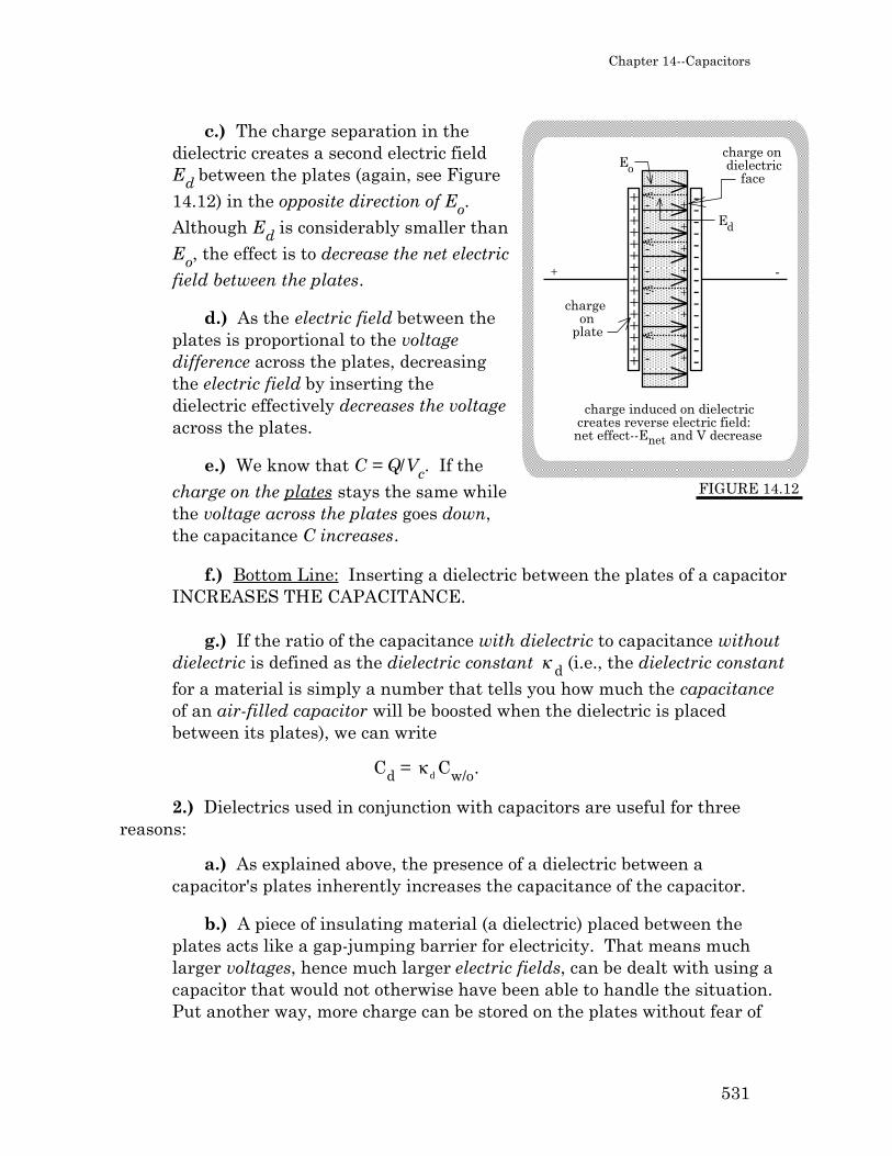
c.) The charge separation in thedielectric creates a second electric fieldEd between the plates (again, see Figure14.12) in the opposite direction of Eo.Although Ed is considerably smaller thanEo, the effect is to decrease the net electric
field between the plates.
d.) As the electric field between theplates is proportional to the voltagedifference across the plates, decreasingthe electric field by inserting thedielectric effectively decreases the voltageacross the plates.
e.) We know that C = Q/Vc. If thecharge on the plates stays the same whilethe voltage across the plates goes down,the capacitance C increases.
f.) Bottom Line: Inserting a dielectric between the plates of a capacitorINCREASES THE CAPACITANCE.
g.) If the ratio of the capacitance with dielectric to capacitance withoutdielectric is defined as the dielectric constant κ d (i.e., the dielectric constant
for a material is simply a number that tells you how much the capacitanceof an air-filled capacitor will be boosted when the dielectric is placedbetween its plates), we can write
Cd = κ d Cw/o.
2.) Dielectrics used in conjunction with capacitors are useful for threereasons:
a.) As explained above, the presence of a dielectric between acapacitor's plates inherently increases the capacitance of the capacitor.
b.) A piece of insulating material (a dielectric) placed between theplates acts like a gap-jumping barrier for electricity. That means muchlarger voltages, hence much larger electric fields, can be dealt with using acapacitor that would not otherwise have been able to handle the situation.Put another way, more charge can be stored on the plates without fear of

532
FIGURE 14.13
+Q-Q
-
+
capacitor area Ao
d
breakdown that would otherwise have been the case (breakdown occurswhen the electric field between the plates is so large that charge leaps thegap--once breakdown is achieved in a dielectric-filled capacitor, thecapacitor is ruined).
c.) Due to their insulating properties, dielectrics allow plates to bebrought very close to one another. As the capacitance is inversely pro-portional to the distance d between the plates, this allows for both theminiaturization of capacitors as well as the increasing of a capacitor'scapacitance per unit of plate area.
3.) It is possible to derive an expression for the capacitance of a parallelplate capacitor in terms of its geometric parameters (i.e., its plate area, thedistance between its plates, etc.). It requires the use of the definition ofcapacitance (i.e., C = q/Vc), the relationship between a voltage difference and theelectric field that is set up as a consequence of the charge on the plates (i.e., ∆V =-∫E.dr), the fact that ∆V = (V- - V+) = - Vc, and the electric field function forcharged parallel plates.
Sound nasty? It is.Fortunately for you, all
you need is the bottom line.Sooo . . .
a.) Assuming thedistance between theplates is d meters (seeFigure 14.13), the area ofone plate is Ao square
meters, and the dielectricconstant of the dielectricbetween the plates is κ d ,the capacitance of aparallel plate capacitor is
C = κ dε o
A o
d,
where ε o is called the permittivity of free space and is numerically equal to
8.85x10⁻¹² farads/meter.
Chapter 14--Capacitors
533
Note: Coaxial cables are used in industry for TV and VCR hook-ups. Adielectric-filled coaxial cable with inside radius R1 and outside radius R2 has acapacitance per unit length of
C
L=
2πκ dε o
lnR2
R1
.
E.) Energy Stored in a Capacitor:
1.) Work must be done to charge a capacitor. The energy associated withthat work is stored as electrical potential energy in the electric field createdbetween the capacitor's plates. In other words, we can determine the amount ofenergy stored in a capacitor by determining the amount of work required tocharge the capacitor. Because you have been deprived of some of the moreinteresting (translation: diabolic) derivations, I'll let you see how this plays outmathematically.
a.) To be as general as possible, assume a capacitor of capacitance Cinitially has charge q on its high voltage plate and -q on its low voltageplate. If the voltage across the plates is initially Vc, how much work mustbe done to add an additional dq's worth of charge to the positive plate?
b.) The amount of work we are looking for will equal the amount ofwork required to move the charge dq from one plate to the other (that iseffectively what is happening as electrostatic repulsion pushes dq's worthof positive charge off the capacitor's low voltage plate).
c.) The relationship between the differential work dW done on thedifferential charge dq as it moves through a potential difference (V- - V+) =
-Vc is:
dW/dq = -∆V = +Vc.
d.) Remembering that Vc = q/C, where q is the charge already on theplates, we can rewrite this as:
dW = (Vc)dq= (q/C)dq.
534
FIGURE 14.14
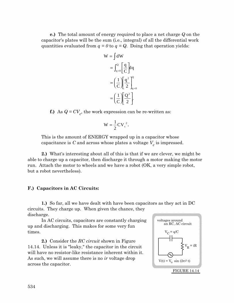
V = iR
V(t) = V sin (2 t)o
R
voltages around an RC, AC circuit
V = q/CC
e.) The total amount of energy required to place a net charge Q on thecapacitor's plates will be the sum (i.e., integral) of all the differential workquantities evaluated from q = 0 to q = Q. Doing that operation yields:
W dW
qC
dq
Cq
CQ
q
Q
q
Q
=
=
=
=
∫
∫ =
=
0
2
0
2
12
12
.
f.) As Q = CVc, the work expression can be re-written as:
W = 1
2CVc
2.
This is the amount of ENERGY wrapped up in a capacitor whosecapacitance is C and across whose plates a voltage Vc is impressed.
2.) What's interesting about all of this is that if we are clever, we might beable to charge up a capacitor, then discharge it through a motor making the motorrun. Attach the motor to wheels and we have a robot (OK, a very simple robot,but a robot nevertheless).
F.) Capacitors in AC Circuits:
1.) So far, all we have dealt with have been capacitors as they act in DCcircuits. They charge up. When given the chance, theydischarge.
In AC circuits, capacitors are constantly chargingup and discharging. This makes for some very funtimes.
2.) Consider the RC circuit shown in Figure14.14. Unless it is "leaky," the capacitor in the circuitwill have no resistor-like resistance inherent within it.As such, we will assume there is no ir voltage dropacross the capacitor.

Chapter 14--Capacitors
535
Though there is, in theory, no resistor-like resistance to charge flowassociated with the capacitor, capacitors do have a frequency-dependent resistivenature. Not obvious? Consider the following:
a.) The voltage drop across a capacitor is defined as:
VC = q/C,
where q is the magnitude of charge on one capacitor plate and C is thecapacitor's capacitance.
b.) To make the evaluation easier later on, let's assume the powersupply's voltage is characterized as a sine function (a cosine function wouldalso work--it would just be a little messier to deal with). With that as-sumption, a Kirchoff's Loop Equation for this circuit (see Figure 14.14)becomes:
- q/C - iR + Vo sin (2 νt) = 0.
Manipulating, we get:
q/C + iR = Vo sin (2 νt),
where q is a time varying quantity in the expression (we could denote it q(t)but, for simplicity, we will leave it as presented).
c.) Though you will never have to derive this on a test, we need anexpression for the resistive nature of the capacitor. To do this:
i.) Assume the resistor-like resistance in the circuit is negligible(i.e., that R = 0). In that case, Kirchoff's Law becomes:
q/C = Vo sin (2 νt) ⇒ q = CVo sin (2 νt).
ii.) Remembering that i = dq/dt, we can write:

536
low frequency voltage
FIGURE 14.15
time interval duringwhich there exists a large charge on the capacitor
t
i o
i =dq
dt
=d CV o sin(2πνt)[ ]
dt
= CV o (2πν) cos(2πνt)
=V o cos(2πνt)
1
2πνC
(Equation B).
3.) Ohm's Law maintains that the current through an element must equalthe voltage across the element divided by a quantity that reflects the resistivenature of the element. In the above expression, the voltage across the element isVocos(2ν t). That means the resistive nature of the capacitor must be 1/(2ν C).
a.) In fact, this is the frequency-dependent resistive nature of acapacitor. It is called the capacitive reactance, its symbol is XC, and itsunits are ohms. Summarizing, we can write:
XC = 1
2πνC (ohms),
where the capacitance C must be written in terms of farads (versus leavingit in microfarads or whatever).
4.) Does the frequency-dependent expression for the resistive nature of acapacitor (i.e., its capacitive reactance) make sense? Consider:
a.) Assume the voltage of a power supply runs at low frequency.
i.) Examining the low fre-quency signal shown in Figure14.15, it is evident that the sig-nal is changing very slowly andthat there is a respectableamount of charge on the capaci-tor a fair portion of the time. Inother words, the capacitor hasplenty of time to charge up and,on the average, the voltage (q/C)

Chapter 14--Capacitors
537
high frequency voltage
FIGURE 14.16
the current charges and discharges the cap so fast that the capacitor's voltage, on average, goes to zero
t
i o
across the capacitor is relatively large.
ii.) Because the capacitor's voltage is relatively large on average,the voltage across the resistor will be relatively small. This implies asmall current in the circuit.
b.) Bottom line #1: The current in an RC circuit will be relativelysmall (i.e., edging toward a readable zero) when a low frequency signalpasses through the circuit. That means we would expect the capacitivereactance (the resistive nature of the capacitor) to be large at lowfrequencies. This is exactly what our expression predicts (i.e., when ν issmall, XC = 1/(2ν C) is large).
c.) Assume the voltage of a power supply now runs at high frequency.
i.) Examining the highfrequency signal shown inFigure 14.16, it is evident thatthe signal is changing very fast.There are not great spans oftime during which the capacitoris charged, hence there are notgreat spans of time during whichthe voltage across the capacitoris high. In fact, the voltage (onthe average) is low (remember,the time average of a highfrequency sine wave is zero even over relatively small time intervals).
ii.) A small voltage across the capacitor (on average) means a largevoltage across the resistor. This implies a large current in the circuit.
d.) Bottom line #2: The current in an RC circuit will be relatively largewhen a high frequency signal passes through the circuit. That means wewould expect the capacitive reactance to be small at high frequencies. Thisis exactly what our expression predicts (i.e., when ν is large, XC is small).
e.) Summary: A capacitor in an AC circuit passes high frequencysignals while damping out low frequency signals. As such, capacitors aresometimes referred to as high pass filters.

538
i
t
voltage across a capacitor in an AC circuit
t
the capacitor's voltage (top graph) LAGS the circuit's current by a quarter cycle
FIGURE 14.18
the slope V/ t is maximum, so the current ( q / t) is maximum at this point in time
current in the circuit
V = q/CC
FIGURE 14.17
( q/ t)
the slope V/ t is zero, so the current ( q / t) is also zero at this point in time
5.) The second point to note about the time dependent current expressionwe derived above is its form. By assuming a power supply voltage that isproportional to sin (2ν t), and assuming that the net resistance in the circuit iszero, we find that the circuit's current is proportional to cos (2ν t). Examiningthe graph of these two functions allows us to conclude that in this situation thevoltage across the capacitor lags the current through the capacitor (i.e., thecircuit's current) by /2 radians.
Does this make sense?
a.) The voltage across acapacitor is proportional to thecharge on the capacitor (i.e.,VC = q/C). Figure 14.17depicts a graphicalrepresentation of this.
b.) Current is defined asthe amount of charge thatpasses a particular point perunit time (i.e., i = dq/dt).
c.) The slope of the capaci-tor's voltage function is
dVC/dt = (1/C)(dq/dt)= i/C.
d.) In other words, agraph of the slope of thecapacitor's voltage functiongives us a modified currentfunction. Figure 14.18 showsthis.
e.) In comparing the graphs, it is evident that the voltage across thecapacitor LAGS the current in the circuit by one quarter of a cycle, or /2radians.
Big Note: This /2 phase shift exists ONLY if there is no resistor-likeresistance in the circuit. As there will never be a case in which there is absolutely

Chapter 14--Capacitors
539
no resistor-like resistance in a circuit, the phase shift in a real RC circuit willnever be /2. Calculating what it actually is in a given case is something we maydo later, but not now.
540
R
C
100 volts
switch
plate Aplate B
R C
switch closed at t = 0
V = 100 voltso
QUESTIONS & PROBLEMS
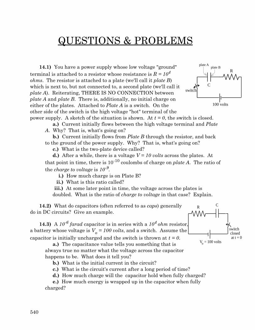
14.1) You have a power supply whose low voltage "ground"terminal is attached to a resistor whose resistance is R = 104
ohms. The resistor is attached to a plate (we'll call it plate B)which is next to, but not connected to, a second plate (we'll call itplate A). Reiterating, THERE IS NO CONNECTION betweenplate A and plate B. There is, additionally, no initial charge oneither of the plates. Attached to Plate A is a switch. On theother side of the switch is the high voltage "hot" terminal of thepower supply. A sketch of the situation is shown. At t = 0, the switch is closed.
a.) Current initially flows between the high voltage terminal and PlateA. Why? That is, what's going on?
b.) Current initially flows from Plate B through the resistor, and backto the ground of the power supply. Why? That is, what's going on?
c.) What is the two-plate device called?d.) After a while, there is a voltage V = 10 volts across the plates. At
that point in time, there is 10-10 coulombs of charge on plate A. The ratio ofthe charge to voltage is 10-9.
i.) How much charge is on Plate B?ii.) What is this ratio called?
iii.) At some later point in time, the voltage across the plates isdoubled. What is the ratio of charge to voltage in that case? Explain.
14.2) What do capacitors (often referred to as caps) generallydo in DC circuits? Give an example.
14.3) A 10-6 farad capacitor is in series with a 104 ohm resistor,a battery whose voltage is Vo = 100 volts, and a switch. Assume thecapacitor is initially uncharged and the switch is thrown at t = 0.
a.) The capacitance value tells you something that isalways true no matter what the voltage across the capacitorhappens to be. What does it tell you?
b.) What is the initial current in the circuit?c.) What is the circuit's current after a long period of time?d.) How much charge will the capacitor hold when fully charged?e.) How much energy is wrapped up in the capacitor when fully
charged?
Chapter 14--Capacitors
541
switch
R
Vo
C2
C1
openR
Vo
C1 C2
close
when switches are thrown
to disconnect battery
to re-connect capacitors
S2
S1
f.) Where is the energy stored in the capacitor?g.) You are told that the time constant for the system is 10-2 seconds.
i.) What does that tell you about the system?ii.) How much charge will be associated with the capacitor after at
time equal to one time constant?iii.) Where will the charge alluded to in Part g-ii be found?
h.) After a very long time, the switch is opened. What happens to thecapacitor? Will it hold its charge forever?
i.) At t = 1 second, the current is i1. At t = 2 seconds, the current is i2.At t = 4 seconds, the current is i4, and at t = 8 seconds, the current is i8. Isi2/i1 going to give you the same ratio as i8/i4?
14.4) Can you have capacitance if you have only one plate?
14.5) You have a series combination of capacitors.a.) What happens to the equivalent capacitance when you add another
capacitor?b.) What is common to all the capacitors in the series combination?
14.6) You have a parallel combination of capacitors.a.) What happens to the equivalent capacitance when you add another
capacitor?b.) What is common to all the capacitors in the
parallel combination?
14.7) You charge up two single capacitors that are inparallel. You disconnect the battery. What happens tothe current in the system when you do this?
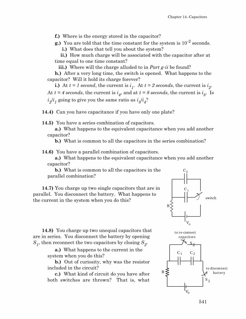
14.8) You charge up two unequal capacitors thatare in series. You disconnect the battery by openingS1, then reconnect the two capacitors by closing S2.
a.) What happens to the current in thesystem when you do this?
b.) Out of curiosity, why was the resistorincluded in the circuit?
c.) What kind of circuit do you have afterboth switches are thrown? That is, what

542
R
Vo
C
2C
initially down
d/2
d
capplate
capplate
kind of relationship will exist between the capacitors after the throw?
14.9) You use a battery whose voltage is Vo to chargeup a capacitor C. When fully charged, there is q's worth ofcharge on the cap. You then disconnect the capacitor fromthe battery and reconnect it to a second unchargedcapacitor whose capacitance is 2C (in the sketch, thisdisconnection, then reconnection, is done with the switch).After the switch is thrown:
a.) Before the charge on C can redistribute,what is the voltage across the second capacitor?
b.) How will the charge redistribute itself?That is, how much charge ends up on the second capacitor?
14.10) You charge up a parallel plate capacitor that has air between itsplates. Once charged, you disconnect it from the battery, then insert a piece ofplastic (an insulator) between the plates. The amount of charge on the capacitordoes not change (being disconnected from the circuit, it has no place to go), but thevoltage across the capacitor does change.
a.) What is the insulator usually called in these situations?b.) How and why does the voltage change (up, down, what?)?c.) What happens to the capacitance of the capacitor?d.) What happens to the energy content of the capacitor? If it goes
up, from whence did the new energy come? If it goes down, where did itgo?
14.11) You have a parallel plate capacitor with air between its plates hookedup to a power supply whose voltage is Vo. Without disconnecting the battery, youcarefully insert a piece of plastic between the plates.
a.) What happens to the voltage across the capacitor?b.) What happens to the capacitor's capacitance?c.) What happens to the charge on the capacitor's plates?
14.12) Between the plates of one air-filled capacitor, youinsert a dielectric whose dielectric constant is k and whosethickness is half the plate separation. Between the plates of asecond cap, you insert a piece of metal whose thickness is alsohalf the plate separation. (Both situations look like the sketch.)After some nasty Calculus, the capacitance expression for the
dielectric situation is found to be C = 2ε o
A
d
2k
1+ k
.
Chapter 14--Capacitors
543
120 volts
20switchclosesat t=0
6 f 12 f
(a) (b)120 volts
20switchclosesat t=0
6 f
12 f
FIGURE I
(a) (b) (c) (d) (e)
FIGURE II
a.) Which modified capacitor will end up with the greater capacitance?b.) What is the ratio of the two capacitances?
14.13) You have a capacitor in series with a switch, a resistor, and a powersupply. At t = 0, you throw the switch and current begins to flow.
a.) For the amusement of it, draw the circuit.b.) If the capacitor had been half as big, how would current flow? That
is, would the cap have charged faster or slower? Justify your response.
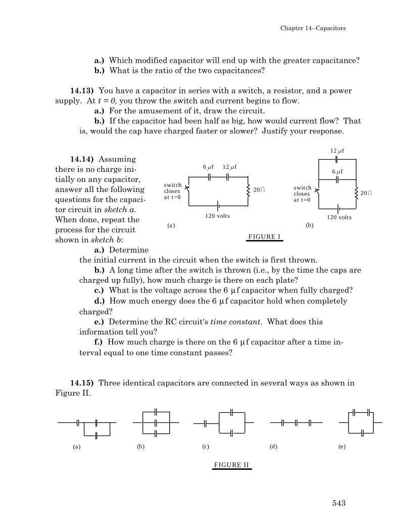
14.14) Assumingthere is no charge ini-tially on any capacitor,answer all the followingquestions for the capaci-tor circuit in sketch a.When done, repeat theprocess for the circuitshown in sketch b:
a.) Determinethe initial current in the circuit when the switch is first thrown.
b.) A long time after the switch is thrown (i.e., by the time the caps arecharged up fully), how much charge is there on each plate?
c.) What is the voltage across the 6 µ f capacitor when fully charged?d.) How much energy does the 6 µ f capacitor hold when completely
charged?e.) Determine the RC circuit's time constant. What does this
information tell you?f.) How much charge is there on the 6 µ f capacitor after a time in-
terval equal to one time constant passes?
14.15) Three identical capacitors are connected in several ways as shown inFigure II.

544
C
CC
C
C
FIGURE III
a.) Order the combinations from the smallest equivalent capacitance tothe largest; and
b.) Which combination has the potential of storing the most energy?
14.16) A parallel plate capacitor is connected to a 20 volt power supply. Oncecharged to its maximum possible Q, the capacitor's plates are separated by afactor of four (that is, the distance between the plates is quadrupled) while thecapacitor is kept hooked to the power supply. As a consequence of this change ingeometry:
a.) How will the capacitor's capacitance change?b.) How will the charge on the capacitor change?c.) How will the energy stored in the capacitor change?d.) If a dielectric (κ d = 1.6) had been placed between the plates of the
original setup, what would the new capacitance have been?
14.17) Determine:a.) The equivalent capacitance of the
circuit shown in Figure III.b.) Assuming each capacitor's capacitance
is 25 mf, how much energy can this systemstore if it is hooked across a 120 volt battery?
14.18) The capacitors in the circuit shown in
120 volts
20
switch closes at t=0
12 f
FIGURE IV
i1
i2
i3
30
6 f
Figure IV are initially uncharged. At t = 0,the switch is closed. Knowing the resistor andcapacitor values:
a.) Determine all three initial cur-rents in the circuit (i.e., the currentsjust after the switch is closed).
b.) Determine all three currents inthe circuit after a long period of time(i.e., at the theoretical point t = ∞).
c.) Without solving them, write outthe equations you would need to solve ifyou wanted to determine the currents in the circuit at any arbitrary pointin time. Be sure you are complete.
d.) Determine the total charge the 6 mf capacitor will accumulate (i.e.,the amount of charge on its plates at t = ∞).
e.) Once totally charged, how much energy do the capacitors hold?

Chapter 14--Capacitors
545
f.) After a very long time (i.e., long after the capacitors have fullycharged), the switch is opened. How long will it take for the two capacitorsto dump 87% of their charge across the 30 Ω resistor?
14.19) An AC voltage source is found to produce a 12 volt peak to peak signalat 2500 hertz.
a.) Characterize this voltage as a sine function.b.) Determine the RMS voltage of the source.c.) It is found that when a capacitor and resistor are placed across the
source as characterized above, an ammeter in the circuit reads 1.2 amps.What is the maximum current drawn from the source?
14.20) An RC circuit is hooked across an AC power supply. Which of thefollowing statements are true (there can be more than one)? Explain eachresponse.
a.) The RMS voltage across the resistor is the same as the averagevoltage across the resistor.
b.) The RMS voltage across the resistor is equal to R times the RMScurrent through the resistor.
c.) The RMS voltage across the resistor will be very large if thecapacitive reactance is very large.
d.) The RMS current in the circuit will be very large if the capacitivereactance is very small.
e.) A decrease in frequency will increase the voltage across thecapacitor.
f.) An increase in the capacitance will increase the current in thecircuit for a given frequency.
g.) A decrease in frequency will increase the voltage across theresistor.
14.21) Why won't a capacitor allow low frequency AC current to flow throughit?
14.22) What is the measure of a capacitor's net resistive nature? That is,what is it called, what are its units, and how is it calculated?

546